Kohler 3 5Cfz 4Cz 6 5Cz Users Manual Operation Manual, 4/6.5CZ 3.5/5CFZ Spec 125217 (TP 5695)
3.5CFZ, 4CZ, 5CFZ, 6.5CZ Kohler-TP-5695
3.5CFZ, 4CZ, 5CFZ, 6.5CZ to the manual a8fdd3f3-7368-43a4-a491-42a86ec68384
2015-01-21
: Kohler Kohler-3-5Cfz-4Cz-5Cfz-6-5Cz-Users-Manual-220100 kohler-3-5cfz-4cz-5cfz-6-5cz-users-manual-220100 kohler pdf
Open the PDF directly: View PDF ![]() .
.
Page Count: 81

Operation and
Installation Manual
MarineGenerator Sets
Models:
3.5CFZ
4CZ
5CFZ
6.5CZ
TP-5695 12/93

Engine exhaust fromthisproductcontains
chemicalsknowntotheStateofCaliforniatocause
cancer,birth defects,orother reproductive harm.
WARNING
CaliforniaProposition 65
TP-5695 12/93 Table ofContents
TableofContents
SUBJECTPAGE SUBJECTPAGE
SafetyPrecautions and Instructionsi.......
Reference Materialviii.......................
Routine ServiceParts x......................
GlossaryofAbbreviations xi................
Section 1.Specifications 1-1..................
Introduction 1-1...............................
Specifications1-1.............................
GeneralSpecifications1-1...................
Generator1-2..............................
Engine 1-3.................................
Accessories1-5..............................
ServiceViews1-6.............................
Section 2.Operation 2-1......................
PrestartChecks 2-1...........................
Controller2-2................................
Starting 2-3..................................
Stopping 2-3.................................
CircuitProtection 2-4..........................
Engine SafetyShutdownSwitches2-4...........
RemotePanels(Optional)2-6..................
Section 3.ScheduledMaintenance 3-1.........
ServiceSchedule 3-2..........................
Lubrication System3-4........................
Specifications3-4...........................
Oil Check 3-4..............................
Adding Oil 3-5..............................
Oil Change/Oil FilterChange 3-5..............
FuelSystem3-6..............................
Specifications3-6...........................
FuelPumpScreen 3-7.......................
Carburetor/Choke Lubrication 3-8.............
CarburetorAdjustments3-8..................
Ignition System3-9............................
Ignition SystemService 3-9..................
SparkPlugs3-9............................
Cooling Systems—Closed/HeatExchanger3-12...
Filling and Checking 3-12.....................
Flushing and Cleaning 3-14...................
Anticorrosion Zinc3-16.......................
PressureCap 3-17...........................
Siphon Break3-17...........................
AirCleanerand Mixing Elbow3-17...............
Servicing AirCleaner3-17....................
Servicing Mixing Elbow3-17...................
Battery3-18...................................
Cleaning 3-18...............................
Checking Electrolyte Level3-18................
Checking SpecificGravity3-18................
Charging 3-19...............................
ValveAdjustment3-20..........................
Governor3-22.................................
Lubrication 3-22.............................
GovernorAdjustment3-22....................
Wattage Requirements3-23.....................
GeneratorService 3-23.........................
General3-23................................
Storage Procedure 3-24........................
Section 4.Troubleshooting 4-1................
Engine 4-1...................................
ElectricalSystem4-3..........................
Generator4-4................................
Section 5.Wiring Diagrams 5-1...............
Section 6. Installation 6-1.....................
Introduction 6-1...............................
GeneratorSelection and
Wattage Requirements6-1.....................
Lighting Load 6-1...........................
MotorLoads6-1............................
Appliance Loads6-2........................
Kilowatt Derating 6-2........................
Location 6-4..................................
General6-4................................
Space 6-4.................................
Mounting 6-4...............................
Ventilation 6-4................................
FuelSystems6-5.............................
FuelSupply6-5............................
Anti-Siphon Provisions6-6...................
FuelLines6-6..............................
FuelPump Lift Capabilitiesand
FuelConsumption 6-6.......................
Cooling Systems6-7..........................
General6-7................................
Closed/HeatExchanger6-8..................
ExhaustSystems6-9..........................
General6-9................................
AboveWaterline 6-11........................
Mid/BelowWaterline 6-11.....................
ElectricalSystems6-12.........................
ACVoltage Connections6-12..................
Installation inSteelorAluminumVessels6-12...
Battery6-13.................................
Wiring 6-13.................................
RemoteStartSwitchConnection 6-14..........
Section 7. Installation Drawings 7-1...........
Section 8.PartsOrdering Instructions 8-1.....
Section 9.Operating HourService Log 9-1.....
TP-5695 12/93 SafetyPrecautionsand Instructionsi
Safety Precautions and Instructions
Ageneratorset, like anyotherelectro-mechanical
device,can pose potentialdangerstolife and limbif
improperlymaintained orimprudentlyoperated.The
bestwayto preventaccidentsisto be aware of the
potentialdangersand to always use good common
sense. Inthe interestofsafety,some general
precautionsrelating tothe operation ofa generatorset
follow.Keep theseinmind.Thismanualcontains
severaltypesofsafetyprecautionswhich are explained
below.
DANGER
Dangerisusedtoindicatethepresenceofahazardthat
will causeseverepersonal injury,death,orsubstantial
propertydamage if the warning isignored.
WARNING
Warning isused toindicatethe presence ofa hazard
thatcan causeseverepersonal injury,death,or
substantialpropertydamage if the warning isignored.
CAUTION
Cautionisused toindicatethepresence ofahazardthat
will orcan causeminorpersonal injuryorproperty
damage if the warning isignored.
Safetydecalsare affixed tothe generatorsetin
prominentplacesto advisethe operatororservice
technician ofpotentiallyhazardous situations.The
decalsarereproduced heretoimprove operator
recognition and therebyincrease decaleffectiveness.
Forafurtherexplanationofdecalinformation,reference
theaccompanying safetyprecautions.Beforeoperating
orservicing the generatorset, be sureyou understand
the message of these decals.Replace decalsifmissing
ordamaged.
NOTE
Noteisusedto notifypeople ofinstallation,operation,or
maintenanceinformation thatisimportantbutnot
hazard-related.
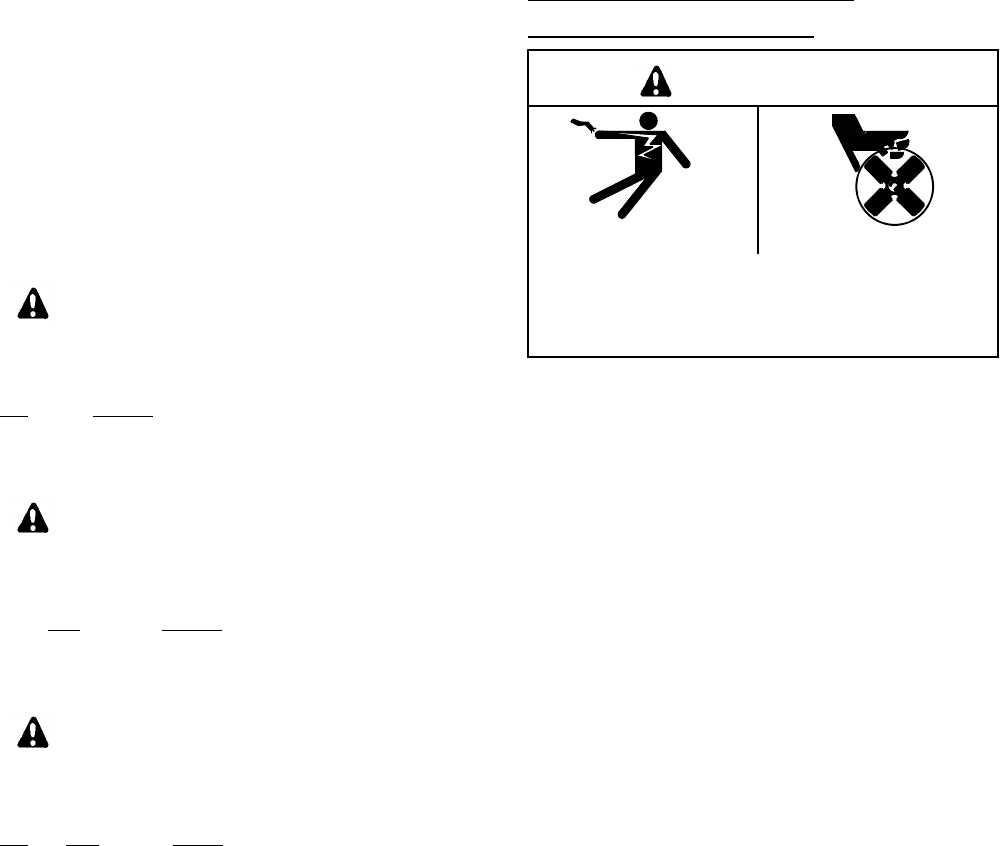
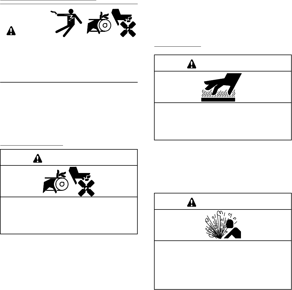
HAZARDOUS VOLTAGE/
ELECTRICALSHOCK
WARNING
Hazardous voltage.
Do notoperate generatorsetwithoutall guards
and electricalenclosuresin place.
Moving rotor.
Cancause severeinjuryordeath.
Hazardous voltage cancause severeinjuryor
death.Whereverelectricityispresent, thereisthe
hazardofelectrocution.Takethesameprecautionswith
electricalappliancesinyourcraft thatyou would
observeinyourhome.Open maincircuitbreakeron all
powersourcesbeforeservicing equipment. Makesure
unqualified persons,especially children,cannotgain
access toyourset—keep the compartmentdoorlocked
orsecurelylatchedatall times.Besurethatgeneratoris
properlygrounded.Nevertouch electrical leadsor
applianceswithwethands,when standing inwater,or
on wetground asthe chance ofelectrocution is
especiallyprevalentundersuchconditions.
Hazardous voltage cancause severeinjuryor
death.Usecaution when handling the capacitor;
possible electricalshock can result. Discharge
capacitorby shorting terminalstogether.
Hazardous voltage cancause severeinjuryor
death.Shortcircuits can cause bodilyinjuryand/or
equipmentdamage.Do notcontactelectrical
connectionswithtoolsorjewelrywhile adjustmentsare
made.Removewristwatch,rings,and jewelrythatcan
causeshortcircuits.
Hazardous“backfeed”voltage cancause severe
injuryordeath.Do notconnect to anybuilding/marina
electricalsystemwithoutconnecting through an
approved device and afterbuilding mainswitchisopen.
Backfeedconnectionscancauseseriousinjuryordeath
to utilitypersonnelworking torepaira poweroutage
and/orpersonnel inthe vicinity.Unauthorized
connection maybe unlawful insomestatesand/or
localities.Aship-to-shoretransferswitchmustbe
installed to preventinterconnection ofgeneratorset
powerand shore power.
TP-5695 12/93ii SafetyPrecautionsand Instructions
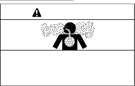
EXHAUSTSYSTEM
WARNING
Carbon monoxide.
Cancause severenausea,fainting,ordeath.
The exhaustsystem mustbe leakproofand
routinelyinspected.
Carbon monoxide cancause severenausea,
fainting,ordeath.Usethe following precautionswhen
installing and operating generatorset. Carbon
monoxide isparticularlythreatening inthatitisan
odorless,colorless, tasteless,nonirritating gas.Be
especially careful ifoperating the generatorwhen
moored oranchored undercalmconditionsasgases
mayaccumulate.Ifoperating the setdockside,moor
yourcraftsothatthe exhaustdischargesonthe leeside
(the side sheltered fromthe wind),and always be
mindfulofothers—makesureyourexhaustisdirected
awayfromotherboatsand occupied buildings.Do not
install exhaustoutletwhere exhaustcan be drawn
through portholes,vents,orairconditioners. If
generatorset’sexhaustdischarge holeisneartoyour
craft’swaterline,DONOTOVERLOADCRAFTso asto
close or restrictexhaustdischarge hole.
Carbon monoxide cancause severenausea,
fainting,ordeath.In addition toroutine inspection of
theexhaustsystem,acarbonmonoxidedetectorshould
be considered.Consultyourboatbuilderormarina for
installation ofapproved detectors.Itisessentialthatall
detectorsbe routinelyinspected forproperoperation.
TP-5695 12/93 SafetyPrecautionsand Instructionsiii
BATTERY
WARNING
Sulfuric acidin batteries.
Cancause severeinjuryordeath.
Use protective gogglesand clothes.Can cause
permanentdamage to eyes,burnskin,and eatholes
inclothing.
Sulfuric acidin batteries cancause severeinjuryor
death.Sulfuricacidin battery can cause permanent
damage to eyes,burnskin,and eatholesinclothing.
Alwayswearsplash-proofsafetygoggleswhenworking
around the battery.Ifbatteryelectrolyteis splashed in
the eyesoron skin,immediatelyflushthe affected area
for15minuteswithlarge quantitiesofclean water.Inthe
caseofeyecontact,seekimmediatemedicalaid.Never
addacidtoabatteryoncethebatteryhasbeenplacedin
service.Doing somayresultin hazardous spattering of
electrolyte.
Explosion cancause severeinjuryordeath.Battery
gases can cause an explosion.Do notsmoke orpermit
flame orsparkto occurneara batteryatanytime,
particularlywhen itisbeing charged.Avoidcontacting
terminalswithtools,etc.topreventburnsand to prevent
sparks thatcouldcause an explosion.Remove
wristwatch,rings,andanyotherjewelrybeforehandling
battery.Neverconnectnegative(--) battery cableto
positive(+)connection terminalofstartersolenoid.Do
not testbattery condition by shorting terminalstogether
orsparks couldignite batterygasesorfuelvapors.Any
compartmentcontaining batteriesmustbe well
ventilated to preventaccumulation ofexplosive gases.
To avoidsparks,do notdisturb battery charger
connectionswhile batteryisbeing charged and always
turnchargeroff before disconnecting battery
connections.When disconnecting battery,remove
negativelead firstand reconnectitlast.
TP-5695 12/93ivSafetyPrecautionsand Instructions
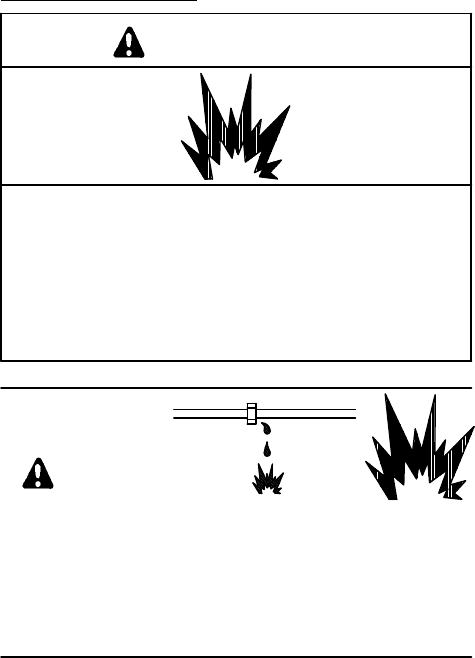
FUELSYSTEM
WARNING
Explosion.
Gasoline vapors cancause explosion and
severeinjuryordeath.
Beforestarting generatorset, operate blower4
minutesand check engine compartment for
gasoline vapors.
WARNING
Explosive fuelvapors.
Cancause severeinjuryordeath.
Useextremecarewhen handling,storing,
and using fuels.
Explosive fuelvapors cancause severeinjuryor
death.Allfuelsarehighlyexplosiveinavaporstate.Use
extremecarewhen handling,storing,and using fuels.
Storefuel inawell-ventilated area awayfrom
spark-producing equipmentand outof the reach of
children.Neveradd fueltothe tankwhilethe engine is
running sincespilled fuelmayignite on contactwith hot
partsorfromignition spark.Do notsmoke orpermit
flame orsparkto occurnearpotentialsourcesofspilled
fuelorfuelvapors.Keepfuellinesand connectionstight
and in good condition—don’treplaceflexiblefuel lines
withrigidlines.Flexiblesectionsare used to avoid
breakage due tovibration.Should anyfuel leakage,fuel
accumulation,orelectricalsparks be noted,DONOT
OPERATEGENERATORSET.Havesystemsrepaired
beforeresuming generatoroperation.
Explosive fuelvapors cancause severeinjuryor
death.Additionalprecautionsmustbe taken when
using the following fuels:
Gasoline—Store gasoline onlyin approved red
containers clearlymarked GASOLINE.Do notstore
gasoline in anyoccupied building.
Explosive fuelvapors cancause severeinjuryor
death.Gasoline vapors can explode and can cause
death orsevereinjury.USCGRegulation 33CFR183
requiresall electricaldevices(ship-to-shoretransfer
switch,remotestartpanel,etc.)tobe“ignitionprotected”
whenusedinagasoline(gaseous)-fueledenvironment.
These electricaldevicesare not“ignition protected”and
are notcertified to operatein a gasoline
(gaseous)-fueled environmentsuch asengine roomor
nearfueltanks.Acceptablelocationswould be
wheelhouseorotherlivingareasshelteredfromrainand
watersplash.
Explosive fuelvapors cancause severeinjuryor
death.Spilled fuelcan cause an explosion.Use a
containertocatchfuelwhen draining fuelsystem.Wipe
up all spilled fuelafterdraining system.
Explosive fuelvapors cancause severeinjuryor
death.Fuel leakage can cause an explosion.Do not
modifythe tankorpropulsion engine fuelsystem.Craft
mustbe equipped withatankallowing one of the two
pickup arrangementsdescribed.Tankand installation
mustconformtoU.S.C.G.Regulations.
Explosive fuelvapors cancause severeinjuryor
death.Fuel leakage can cause an explosion.To
prevent fuel leakage,use pipe sealanton all threaded
fittings.Pipe sealantmustbe suitableforuseinmarine
applicationshaving oil and gasoline environments.
TP-5695 12/93 SafetyPrecautionsand Instructions v
ACCIDENTALSTARTING
WARNING
Accidentalstarting.
Cancause severeinjuryordeath.
Disconnectbattery cablesbeforeworking on
generatorset(negativelead firstand reconnectit
last).
Accidentalstarting cancause severeinjuryor
death.Disconnectbattery cables(remove negative
lead firstand reconnectitlast)to disable generatorset
beforeworking on anyequipmentconnected to
generator.The generatorsetcan be started byremote
start/stop switch unless thisprecaution isfollowed.
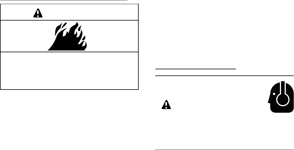
MOVINGPARTS
WARNING
Rotating parts.
Cancause severeinjuryordeath.
Do notoperate generatorsetwithoutall guards,
screens,orcoversin place.
Flying projectiles cancause severeinjuryordeath.
Retorque all crankshaft and rotorhardware after
servicing.When making adjustmentsorservicing
generatorset, do notloosen crankshaft hardware or
rotorthru-bolt. If rotating crankshaft manually,direction
shouldbeclockwise only.Turning crankshaft boltor
rotorthru-boltcounterclockwisecan loosen hardware
and resultinseriouspersonal injuryfromhardware or
pulleyflying off engine while unitisrunning.
Exposedmoving parts cancause severeinjuryor
death.AdditionalPrecautionsRegarding Sound Shield
Equipped Models:
Somescheduled maintenance proceduresrequirethe
generatorset to be running while performing service. If
the sound shield hasbeen removed leaving beltsand
pulleys exposed,be especially carefulof thisarea.
Exposedmoving parts cancause severeinjuryor
death.Keep hands, feet, hair,clothing,and testleads
awayfrombeltsand pulleys when unitisrunning.
Replace guards,covers,and screensbefore operating
generatorset.
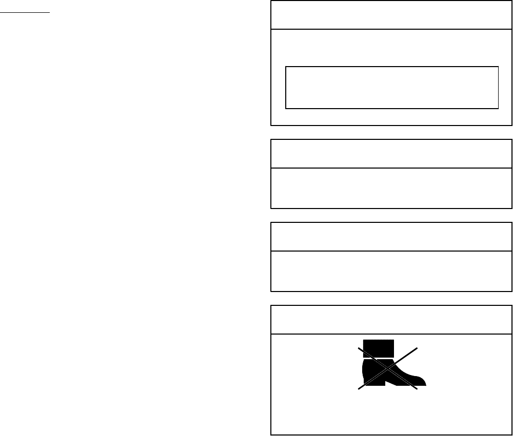
HOTPARTS
WARNING
Hotengine and exhaustsystem.
Cancause severeinjuryordeath.
Donotworkongeneratorsetuntilunitisallowedto
cool.
Hotparts cancause severeinjuryordeath.Do not
touchhotengine parts.Anengine getshotwhilerunning
and exhaustsystemcomponentsgetextremelyhot.
WARNING
Hotcoolantand steam.
Cancause severeinjuryordeath.
Beforeremoving pressurecap stop generator,
allowtocooland loosen pressurecap torelieve
pressure.
Hotcoolantcancause severeinjuryordeath.Allow
engine tocooland release pressurefromcooling
systembefore opening pressurecap.Torelease
pressure,coverthe pressurecap with a thick cloththen
turnitslowly counterclockwisetothe firststop.After
pressure hasbeen completelyreleased and the engine
has cooled,removecap. If generatorsetisequipped
withacoolantrecoverytank,checkcoolantlevelattank.
TP-5695 12/93viSafetyPrecautionsand Instructions
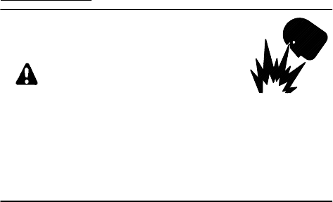
ENGINEBACKFIRE/FLASHFIRE
WARNING
Fire.
Cancause severeinjuryordeath.
Do notsmoke orpermit flame orsparkto occur
nearfuelorfuelsystem.
Aflashfire cancause severeinjuryordeath.Donot
smokeorpermitflameorsparktooccurnearcarburetor,
fuel line, fuelfilter, fuelpump,orotherpotentialsources
ofspilled fuelorfuelvapors.When removing fuel line or
carburetor,useapropercontainertocatch all fuel.
Asuddenbackfire cancause severeinjuryordeath.
Do notoperatewith backfireflame arrestor removed.
Asuddenbackfirecancausesevereinjuryordeath.
Do notoperatewith aircleaner/silencer removed.
Asuddenflashfirecancausesevereinjuryordeath.
Donotsmokeorpermitflameorsparktooccurnearfuel
system.Keepthecompartmentandgeneratorsetclean
and free ofdebristominimizechancesof fire.Wipe up
all spilled fueland engine oil.
HAZARDOUSNOISE
CAUTION
Hazardousnoise.
Cancause loss ofhearing.
Neveroperate generatorwithoutamufflerorwith
faultyexhaustsystem.
TP-5695 12/93 SafetyPrecautionsand Instructions vii
NOTES NOTE
HARDWAREDAMAGE!Engine and generatormay
make use ofbothAmerican Standard and metric
hardware.Besureto usethe correctsizetoolsto
preventrounding ofboltheadsand nuts.
NOTE
Specialattention should be given when checking for
propercoolantlevel.Afterthecoolanthasbeendrained,
itnormallyrequires sometime beforecompleterefill of
the engine waterjacket takesplace.
NOTE
Whenreplacing hardware,do notsubstitutewith
inferiorgradehardware.Screwsand nutsare
availablein differenthardness ratings.American
Standard hardware usesaseriesofmarkingsand
metrichardware usesa numeric systemtoindicate
hardness.Check markingson bolthead and nutsfor
properidentification.
NOTE
When a fusereplacementisrequired,be surefuse has
the same ampererating and isthe sametype (for
example:ABCor3AB,ceramic).Do notsubstitute
“clear”glass-type fusesforceramicfuses. If ampere
rating isunknown orquestionable,see Wiring Diagram.
NOTE
High-mineralcontentsea water (saltwater) can cause
rapid destruction ofall metals.Wipe up all saltwater
spillage on and around generatorsetand keep metal
surfacesfree fromaccumulated saltdeposits.
NOTICE
Thisgeneratorsethas beenrewiredfromits
nameplate voltageto:
246242
NOTICE
Thisisapositive terminalonly.
Do notattach negative lead!
NOTICE
Checkzincanode every100 hoursor3months.
NOTICE
Do notuse as a step.
Standing on gensetcouldimpairoperation ofunit.
NOTE
Splitlock washersmaybe supplied withsomekits. If
splitlock washersaresupplied withkit, theiruseis
optional.
TP-5695 12/93viii ReferenceMaterial
Reference Material
It isrecommended that the following Regulationsand
Standardsbe followed when installing Marine
GeneratorSets.
PleasureCraft
Designed and manufactured tomeetU.S.CoastGuard
Title 33.
U.S.CoastGuardCode ofFederalRegulations
Title 33
SubpartsI--ElectricalSystems
Subparts J--FuelSystems
Title 46
SubchapterF--Marine Engineering
Part58--Main and AuxiliaryMachineryand Related
Systems
Orderthe above publicationsfrom:
SuperintendentofDocuments
U.S.GovernmentPrinting Office
Washington,DC 20402
1-202-783-3238
Boating SafetyCircularCommandant(G-BC)
Boating Statistics (G-BP-1)
U.S.CoastGuardHeadquarters
2100 Second Street, S.W.
Washington,DC 20593-0001
Boating SafetyHotline:1-800-368-5647
American Bureau ofShipping
“RulesforBuilding and Classing SteelVessels”
45 EisenhowerDrive
Paramus,N.J.07652
201-368-9100
LloydsRegistryofShipping
“RulesforClassification ofShips”
17 BatteryPlace
NewYork,N.Y.10004
212-425-8050
UnderwritersLaboratories, Inc.(UL)
PublicationsStock
333 Pfingsten Road
Northbrook, IL 60062
Marine Department: 1-919-549-1400
NFPA 302
NationalFireProtection Association
60 BatterymarchPark
Quincy,MA02269
CustomerService
SocietyofAutomotiveEngineer’s(SAE)
400 CommonwealthDrive
Warrendale,PA 15096
1-412-776-4970
American Boatand YachtCouncil, Inc.(ABYC)
3069 Solomon’sIsland Rd.
Edgewater,MD21037
1-410-956-1050
1-410-974-8112
1-410-956-2737 FAX
IEEE 45
The Institute ofElectricaland
Electronics Engineer’sInc.
345 East47thStreet
NewYork,NY10017
TP-5695 12/93 ReferenceMaterial ix
CommercialVessels
In orderto usethese generatorsetsforcommercial
applicationswhereU.S.CoastGuardTitle46Certificate
isrequired,additionalmodificationswill be necessary.
U.S.CoastGuardCode ofFederalRegulations
Title 46
SubchapterF--Marine Engineering
Part58--Main and AuxiliaryMachineryand Related
Systems
SubchapterJ--ElectricalEngineering
Part111--ElectricalSystems--GeneralRequirements
Part112--Emergency Lighting and PowerSystems
SubchapterT--Small PassengerVessels
(Under100 Gross Tons)
Part182--MachineryInstallation
Part183--ElectricalInstallation
Orderthe above publicationsfrom:
SuperintendentofDocuments
U.S.GovernmentPrinting Office
Washington,DC 20402
1-202-783-3238
American Bureau ofShipping (ABS)
65 Broadway
NewYork,NY10006
OrderABS publicationsfrom:
American Bureau ofShipping
BookOrderSection
45 EisenhowerDrive
P.O.Box910
Paramus,NJ97653-0910
Lloyd’sRegisterofShipping
71 FenchurchStreet
London,EC3M4BS England
MidwestOffice:
Lloyd’sRegisterofShipping
100 SouthYorkStreet, Room226
Elmhurst, IL 60126
1-312-279-5414
AdditionalReferences
The following organizationsprovide a servicewhich
maybe usefultothe generatorsetinstaller.These
organizationsare notregulatoryin nature butrather
provide guidelinesand assistance.Theyarelisted only
asasourceforadditional information.Nosolicitation or
representation isherebygiven.
YachtCorrosion Consultants, Inc.
2970 SeaborgAve.
Ventura,CA93003
1-805-644-1886
Ward’sMarine Electric, Inc.
630 S.W.FlaglerAve.
Ft. Lauderdale,FL 33301
1-305-523-2815
1-800-545-9273
1-305-523-1967 FAX

xRoutine ServicePartsTP-5695 12/93
RoutineService Parts
ContactyourKohlergeneratordealer/distributorfora
completelisting ofservice partsforyourgeneratorset.
PartDescription KohlerPartNo.
Engine:
AirFilter278612
Oil Filter267714
Belt, Timing 267722
Ignition System:
SparkPlug 267713
Sea WaterPumpImpeller229826
ZincAnode 267928
WhiteSprayPaint221318
TP-5695 12/93 GlossaryofAbbreviations xi
GlossaryofAbbreviations
Abbreviationsare used throughout thismanual.Normallyinthe text theywill appearincompleteformwiththe
abbreviation following in parenthesisthe first timetheyare used.Afterthat theywill appearinthe abbreviated form.
The commonlyused abbreviationsareshown below.
Abbreviation Description
ACalternating current
AHWTanticipatoryhigh watertemp.
ALOPanticipatorylowoil pressure
AMamplitude modulation
Amp ampere
Ampsamperes
ANSIAmerican NationalStandardInstitute
APIAmerican PetroleumInstitute
approx.approximate,approximately
A/Rasrequired,asrequested
A/Sas supplied,as stated,as suggested
ASA American StandardsAssociation
assy.assembly
ASTMAmerican SocietyforTesting Materials
ATDC aftertop dead center
ATSautomatictransferswitch
aux.auxiliary
AWGAmerican WireGauge
AWMappliancewiring material
bhp brake horsepower
bmep brakemean effective power
BtuBritishthermalunit
°C Celsiusdegree
cc cubic centimeter
CCAcoldcranking Amps.
CEC Canadian ElectricalCode
cfhcubicfeetperhour
cfmcubicfeetperminute
CIDcubicinch displacement
cmcentimeter,centimeters
cmm cubicmetersperminute
co.company
cont’d.continued
C.S.A.Canadian StandardsAssociation
cu.in.cubicinch,cubicinches
cyl.cylinder
dBA decibels
DC directcurrent
DCR directcurrentresistance
deg.degree
dept. department
dia.diameter
e.g.example given
EMIelectromagneticinterference
etc.etcetera,(and soforth)
ext. external
°F Fahrenheitdegree
fl.oz. fluid ounce, fluid ounces
Abbreviation Description
FMfrequency modulation
fsfull scale
ft. foot, feet
ft. lbs. footpound, footpounds
ga.gauge
gal., gals.gallon,gallons
gal./hr.gallonsperhour
gph gallonsperhour
gpmgallonsperminute
gr.grade
grd.ground
HCHThigh cylinderhead temperature
HEThigh exhaust temperature
Hgmercury(element)
H2Owater
hp horsepower
hr,hrshour
HWThigh watertemperature
Hzhertz(cyclespersecond)
IDinside diameter
in.inch(es)
inc.incorporated
in.lbs.inch pounds
int. internal
int.-ext. internal-external
ISOInternationalStandardsOrganization
Jjoule,joules
JISJapaneseIndustryStandard
kgkilogram,kilograms
kg/cm2kilogramspersquarecentimeter
kgmkilogram meter(s)
kmkilometer,kilometers
kPakiloPascal,kiloPascals
kph kilometersperhour
kVkilovolt
kVA kilovoltamperes
kWkilowatt, kilowatts
kWHkilowatt hour
Lliter,liters
LxWxHlengthxwidthxheight
LED,LEDslightemitting diode
lb., lbs.pound,pounds
L/hr.literperhour,litersperhour
L/min.liter(s)perminutes
LOPlowoil pressure
LPliquefied petroleum
LWTlow watertemperature
m meter,meters
xii GlossaryofAbbreviationsTP-5695 12/93
Abbreviation Description
m3cubicmeter,cubicmeters
max.maximum
MCMone thousand circularmils.
mi.mile,miles
mil one one-thousandth ofan inch
min.minimum
mJmillijoule,millijoules
MJmega joule,mega joules
mm millimeter,millimeters
m3/mincubicmetersperminute
MPamegaPascal
mph milesperhour
MSmilitary standard
mWmilliwatt, milliwatts
MWmegawatt, megawatts
N/Anotavailable
NEC NationalElectricalCode
NEMANationalElectrical
ManufacturersAssociation
NFPA NationalFireProtection Association
NmNewton meter,Newton meters
no., nos.number,numbers
NPTNationalStandardtaperpipe
thread pergeneraluse
N/Rnotrequired
OCovercrank
ODoutside diameter
OEMoriginalequipmentmanufacturer
OSoverspeed,oversize
OVovervoltage
oz.ounce,ounces
Abbreviation Description
PFpowerfactor
pot. potentiometer
ppmpartspermillion
psipoundspersquareinch
pt., pts.pint, pints
qt., qts.quart, quarts
qty.quantity
ref. reference
RFIradiofrequency interference
rmsrootmean square
rpmrevolutionsperinch
SAE SocietyofAutomotiveEngineers
sec.second,seconds
SCR silicon controlled rectifier
spec,specs specification
sq.square
sq.cmsquarecentimeters
sq.in.squareinch,squareinches
tachtachometer
TDC top dead center
temp. temperature
TIFtelephone influencefactor
turbo turbocharger
UNC Unified coarsethread (wasNC)
UNFUnified fine thread (wasNF)
ULUnderwriter’sLaboratories, Inc.
USundersize
Vvolt, volts
VACVoltsalternating current
VDC voltsdirectcurrent
Wwatt, watts

TP-5695 12/93 Specifications1-1
Section 1.Specifications
Introduction
The craft isequipped with a dependable 110 volt
(reconnectableto 110/220 volt),50 Hz;or120 volt
(reconnectableto 120/240 volt),60 Hz single-phase
alternating currentmarine generatorset. Service
requirementsareminimalbutareveryimportant tothe
safe and efficientoperation of the generatorset;
therefore,inspectassociated partsoften. It is
recommended thatan authorized service
dealer/distributorperformrequired servicing to assure
the unitcontinuestomeetU.S.C.G.requirements.
Pleasetakeafewmomentstoread thismanual, then
carefullyfollowallservicerecommendationstokeepthe
setintop condition.Keep thismanualaboardthe craft
forfuturereference.See Figure 1-1foridentification
and location ofcomponents.
Specifications
GeneralSpecifications
3.5CFZ 5CFZ
Dimensions--LxWxH--in.(mm)27.87 x17.50 x16.60
(708 x445 x422)31.07 x18.10 x17.50
(789 x460 x445)
withSound Shield 31.07 x18.10 x17.50
(789 x460 x445)31.07 x18.10 x17.50
(789 x460 x445)
Weight--(wet),lbs.(kg)208 (94)231 (104)
withSound Shield 231 (104)231 (104)
AirRequirements--cfm(L/min.)18 (510)18 (510)
FuelConsumption U.S.gal./hr.(L/hr.)
Load
25%0.42 (1.59)0.44 (1.67)
50%0.50 (1.89)0.54 (2.04)
75%0.59 (2.23)0.66 (2.50)
100%0.68 (2.57)0.80 (3.03)
4CZ6.5CZ
Dimensions--LxWxH--in.(mm)27.87 x17.50 x16.60
(708 x445 x422)31.07 x18.10 x17.50
(789 x460 x445)
withSound Shield 31.07 x18.10 x17.50
(789 x460 x445)31.07 x18.10 x17.50
(789 x460 x445)
Weight--(wet),lbs.(kg)190 (86)231 (104)
withSound Shield 213 (96)231 (104)
AirRequirements--cfm(L/min.)18 (510)18 (510)
FuelConsumption U.S.gal./hr.(L/hr.)
Load
25%0.48 (1.81)0.53 (2.00)
50%0.55 (2.08)0.62 (2.34)
75%0.62 (2.34)0.86 (3.25)
100%0.68 (2.57)1.02 (3.86)

TP-5695 12/931-2Specifications
Generator
3.5CFZ 5CFZ
Rated kW3.5 5
Frequency--Hz50 50
Rated Voltage 110 Volt, 2&3Wire,SinglePhase or110/220 Volt, 3Wire,SinglePhase
Rated Amps(110 Volt)31.8 45.5
Rated Amps(220 Volt)15.9 22.7
RotorResistance(cold) (ohms)4--5 4--5
StatorResistance(cold) (ohms)*
Leads:
1--2,3--4 0.8 0.8
55--66 4.2 4.2
B1--B2 0.08 0.08
4CZ6.5CZ
Rated kW4 6.5
Frequency--Hz60 60
Rated Voltage 120 Volt, 2&3Wire,SinglePhase or120/240 Volt, 3Wire,SinglePhase
Rated Amps(120 Volt)33.3 54.2
Rated Amps(240 Volt)16.7 27.1
RotorResistance(cold) (ohms)3--4 4--5
StatorResistance(cold) (ohms)*
Leads:
1--2,3--4 0.06 0.04
55--66 1.9 2.4
B1--B2 0.09 0.06
3.5CFZ/4CZ5CFZ/6.5CZ
GeneratorType Two-Pole,Rotating Field
Voltage Regulation ±5%
Frequency Regulation ±5%
AngularOperation (Max.)
(in all directions)20° Continuous
Excitation Method Brushless,ExciterWinding/Capacitor
Coupling Type Tapered Shaft--Thru-Bolt
StatorBoltTorque in.lbs.(Nm)260 (29)
Thru-BoltTorque ft. lbs.(Nm)37 (50)
NumberofOutputLeads4,Reconnectable
Insulation (Rotorand Stator) Class F,Epoxy Varnish,VacuumImpregnated
Winding MaterialCopper
Bearing,Numberand Type 1,ReplaceableBall
CircuitProtection:
ControllerReplaceable 10-AmpFuse
BatteryCharging Replaceable 10-AmpFuse
AC CircuitBreakersOptional
*Mostohmmeterswill notgive accuratereadingswhen measuring less than 1 ohm.The statorcan be
considered good ifalowresistancereading (continuity)isobtained and thereisno evidence ofshorted
windings(discoloration).Do notconfusealowresistancereading withareading indicatingashorted winding.

TP-5695 12/93 Specifications1-3
DERATING:All unitsarerated1.0powerfactor.Derateapproximately3.5%per1000 ft.(300 m)above500ft.(150m)
abovesea level.
3.5CFZ,50 Hz:3.5kWat77° F(25° C)and 3.5kWat122° F(50° C).
4CFZ,60 Hz:4kWat77° F(25° C)and 3.5kWat122° F(50° C).
5CFZ,50 Hz:5kWat77° F(25° C)and 4.85 kWat122° F(50° C).
6.5CZ,60 Hz:6.5kWat77° F(25° C)and 6 kWat122° F(50° C).
Engine
Some generalengine specificationsarelisted below.Refertothe appropriateservicesection and the engine service
manualforspecific service details.
3.5CFZ/4CZ5CFZ/6.5CZ
ManufacturerHonda
ModelGX360EV
Cycle 4
NumberCylinders2
Compression Ratio 8:5:1
Displacement--cu.in.(L)21.9(359)
Rated Horsepower--50 Hz10.7(3.5CFZ)10.7(5CFZ)
--60 Hz12.8(4CZ)12.8(6.5CZ)
RPM--50 Hz3000 (3.5CFZ)3000 (5CFZ)
--60 Hz3600 (4CZ)3600 (6.5CZ)
BorexStroke--in.(mm)2.28 x2.68 (58 x68)
ValveMaterialSteelAlloy(JIS SUH3)
ValveClearance--in.(mm) (cold)0.004--0.006 (0.10--0.14)
CylinderBlock MaterialAluminum
CylinderHead CoverTightening
Torque--ft. lbs.(Nm)7(10)
CylinderHead MaterialAluminum
Connecting Rod MaterialSteel
Piston Rings2Compression/1Oil Control
Crankshaft BearingsReplaceableInserts
GovernorGear-Driven Centrifugal
Lubrication SystemPressure
Oil Capacity(withfilter)--U.S.qts.(L)1.48 (1.4)
Oil Type (API)SF,SF/CC,orSF/CD
Oil Pressure--psi(kPa)30--50 (207--345)
FuelType Gasoline,86 orHigher,Octane Unleaded
FuelSystemSingle-Barrel,HorizontalCarburetor
CarburetorChokeAutomatic,Electric
FuelPumpElectric
FuelPump Lift (max.)3ft. (0.9m)
BatteryVoltage 12
BatteryGround Negative
BatteryRecommendation 250 ColdCranking Amps(Min.)

TP-5695 12/931-4Specifications
Engine(Continued)
3.5CFZ/4CZ5CFZ/6.5CZ
SparkPlug Type Resistor,RadioSuppression,14 mm
BPR4HS(NGK)
KohlerPartNumberL92YC(Champion)
R43CFS(AC-Delco)
SparkPlug Gap--in.(mm)0.028--0.031 (0.7--0.8)
SparkPlug Tightening Torque--
ft. lbs.(Nm)15--22 (20--30)
Ignition SystemTransistorized,Breakerless
StarterMotorBendixAutomotiveType
Cooling SystemWater-Cooled,Closed/HeatExchanger
Cooling SystemCapacity--U.S.qts.(L)1.10 (1.00)
CoolantRecoveryTank--U.S.qts.(L)0.38 (0.35)
Thermostat180 °F(82° C)
PressureCap Rating 15 psi(103 kPa)
Engine Firing Order1--2
Ignition Timing B.T.D.C.24° ±2 degrees
ExhaustManifoldtoCylinder
Head Torque 16 ft. lbs.(22 Nm)
WaterPumpAssemblyto
CylinderBlock Torque 7ft. lbs.(10 Nm)
Cooling Fan Torque 16 ft. lbs.(22 Nm)
AirCleanerElbowtoCarburetor
Stud Torque 6ft. lbs.(8.5Nm)
Timing BeltCoverTorque 6 ft. lbs.(8Nm)
GovernorArmShaft NutTorque 7 ft. lbs.(10 Nm)
GovernorCasetoCylinderHead
Torque 7ft. lbs.(10 Nm)
FuelPumpPressureRating 2.0--3.5 psi(13.8--24.1kPa)
BatteryCharging Winding
Resistance--10 Amp0.16--0.24 Ohms
Ignition Coil PrimaryWire
Resistance0.9--1.1Ohms
Ignition Coil Secondary
(SparkPlug WireSide)Resistance0.9--1.1Ohms
(WithSparkPlug Boot/Cap Removed)
Transistorized Ignition AirGap 0.016 ±0.008 in.(0.4±0.2mm)
Timing BeltDeflection 0.16--0.20 in.(4.5mm)@4.4lbs.(2kg)

TP-5695 12/93 Specifications1-5
Accessories
Severalaccessoriesare availabletofinalizethe
installation orto add convenienceto operation and
service.Allthemostcurrentinformationcanbeobtained
by contacting the localauthorized Kohler
dealer/distributor.Available accessoriesat the time of
printof thispublication are asfollows.
Sound Shield
(Optionalon 3.5CFZ/4CZ;
Standardon5CFZ/6.5CZ)
Providesforhighlyeffectivesilencing,ease ofaccess
forengine/generatorservicing,lowmaintenance,
excellentdurability,and safety.
SeawaterStrainer
The seawaterstrainerwithclearviewing container,
allowseasy cleaning and maintenance.Threaded for
1/2NPTfittings.
Ship-to-ShoreTransferSwitch
The ship-to-shoretransferswitch allowsimmediate
switching to generatorsetpowerorshore power
protecting the electricalsystemfromthe possibilityof
simultaneous connection ofboth powersources.
RemoteStartPanel
Allows starting/stopping fromalocation remote of the
generatorset. Supplied with 15 foot(4.6m)connection
harness.Overall mounting dimensionsare41/16 in.
(103mm)by2 1/8in.(54mm)witha minimum mounting
depth of2 1/4in.(57 mm).
SenderKit
Providesgauge sendersforthe remotestartand
two-meterpanelkitand the remotestartand four-meter
panelkit. The gauge senderkitisrequired tomakethe
oil pressure and watertemperature gaugesfunctional.
CircuitBreakers
See pricelistordealer/distributorforproperapplication
ofcircuitbreakers.
ModelAmpsPoles
4CZ/3.5CFZ 18 2
4CZ/3.5CFZ 35 1
4CZ/3.5CFZ 20 1
6CZ/5CFZ 30 2
6CZ/5CFZ 55 1
6CZ/5CFZ 25 2
6CZ/5CFZ 20 1
RemoteStartand
Four-MeterPanelKit
Allows starting/stopping fromalocation remote of the
generatorset. The illuminated meters/gaugesinclude a
DC voltmeter,engine oil pressure gauge,water
temperature gauge,and an hourmeterwhichrecords
totalgeneratorsetoperating hours.Overall dimensions
are9in.(229 mm)by6in.(152 mm)with a minimum
mounting depth of4in.(102 mm).Requiresremote
connection/extension harness and senderkit.
RemoteStartand
Two-MeterPanelKit
Allows starting/stopping fromalocation remote of the
generatorset.The illuminatedgaugesincludeengineoil
pressure gauge and watertemperature gauge.Overall
dimensionsare6in.(152 mm)by6in.(152 mm)with a
minimum mounting depth of2 3/4in.(70 mm).Requires
remoteconnection/extension harness and senderkit.
RemoteConnection/
Extension Harness
Providesadditionalwiring between all remote panels
and controllerconnector.One required foreachremote
meterpanelkit. Availablein15ft. (46 m)and 25 ft.
(76 m)lengths.Extension limited to a totalof fourkits
and 75 ft. (23 m).
12-InchRemoteWiring Harness
Thisone foot(0.3m)wiring harness hasa 6-pin
connectoron one end whichis keyed tocontrollerbox
connector.The otherend haspigtailsforconnection to
customer-supplied startswitch,generator“on”light,
hourmeter,etc.
Siphon Break
Preventsthe siphoning ofwaterintothe engine on
generatorsetsinstalled belowthe waterline.
TP-5695 12/931-6Specifications
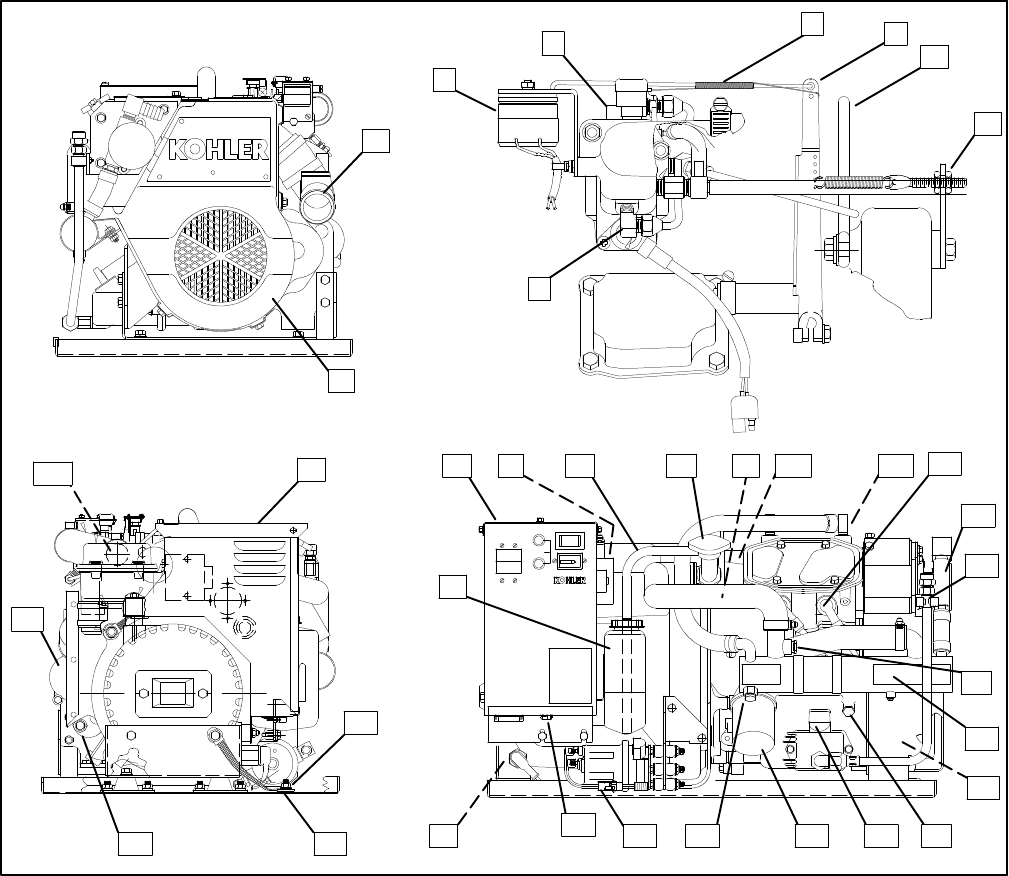
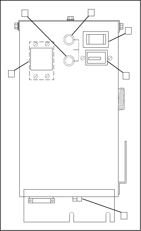
Service Views
TOTALHOURS
00 0
E
00 1/10
10A
FUSE
BATT.
CHRG.
INPUT
2
9
45
36
35
30
29 28 27 26 25 24 23
21
19
33
258000-D
1
34
STOP START
10 17
16131211 14
31 15
18
20
67
8
32
3
22
Figure 1-1.Service Views(typical)
1.MixerElbow(ExhaustWaterOutlet)
2.BeltGuard
3.ElectricChokeRotarySolenoid
4.Carburetor
5.GovernorLinkage
6.GovernorArm
7.Lifting Eye
8.Speed Adjustment(IdleSpeed)
9.Antidieseling Solenoid
10.Controller
11.BatteryChargerVoltage Regulator
12.CoolantOverflow Hose
13.Cooling SystemPressureCap
14.High WaterTemperatureSafetyShutdown
Switch
15.Thermostat
16.High ExhaustTemperatureShutdown
Switches(2)
17.SparkPlugs
18.SeawaterPump
19.Oil Drain
20.WaterTemperatureSender (Optional)
21.HeatExchanger
22. Ignition Coil/Module
23.LowOil PressureShutdownSwitch/Sender
(SenderOptional)
24.Oil Dipstick (Oil Check/Oil Fill)
25.Oil Filter
26.Anticorrosion Zinc
27.ElectricFuelPump
28.RemotePanelConnector
29.PositiveBatteryLead Connection
30.CoolantRecoveryTank
31.AirFilter
32.Nameplate
33.NegativeBatteryLead Connection
34.EquipmentGround Lug
35.StarterSolenoid
36.StarterMotor
TP-5695 12/93 Operation 2-1
Section 2. Operation
PrestartChecks
Toinsurecontinued satisfactoryoperation, the following
items shouldbechecked before eachstart-up.
BACKFIREFLAMEARRESTOR:Aircleanermustbe
cleanandproperlyinstalledtopreventunfilteredairfrom
entering engine.See Maintenance--AirCleaner.
BATTERY:Removecapsand check the electrolyte
levelofeachcell (batterieswithfillercapsonly);add
distilled waterifnecessary.Check tomakesureitis
connected correctly.Batteryinstallation and
connectionsmustmeetCoastGuardStandards.
Battery shouldbeserviced byauthorized personnel
only.See Maintenance--Battery.
COMPARTMENT:Keep the engine roomor
compartmentclean and dry.Check forfueloroil leaks.
Check the condition of fuelsystem,exhaustpiping,
hoses,and muffler;have anyfaulty components
repaired before getting underway.Open hatchto airout
compartmentand use“ignition-protected”bilge
blowers,ifrequired, toclearfumesfromarea before
eachstart-up. If fuel leaks, fumes,exhaustgases,or
electricalsparks are noted,arrange forqualified
personneltomake necessaryrepairsbefore operating
generatorset.
FUEL LEVEL:Makesurethe fueltanks arefull and the
fuelsystemprimed foroperation.See
Maintenance--FuelSystem.
OIL LEVEL:Should be atornearMax.mark.Add oil as
neededtobringleveluptothisrange.SeeMaintenance
Lubrication System.
COOLING:The coolantlevelon closed-type heat
exchangersystems can be checked using the coolant
recoverytank,ifused.TheMINmarkindicatesfull when
coldandtheMAXmarkindicatesfullwhen hot. Maintain
the coolantlevelbetween thesemarks. It is
recommended thatcoolantlevelon closed systemsbe
periodically checked byremoving pressurecap.Do not
solelyrelyon level incoolantrecoverytank.
Add freshcoolantuntil level isjustbelowoverflowtube
opening.See Maintenance--Cooling Systems.
SEAWATERPUMP PRIMING:The seawaterpump
mustbe primed beforeinitialstart-up.To prime pump,
closeseacock and removethe hosefromwaterfilter
outlet. Fill hose and pumpwithclean water.Replace
hose and open seacock.Check forpump operating on
start-up byobserving waterdischarge fromexhaust
outlet.
TP-5695 12/932-2Operation
Controller
Foridentification and location ofcontrolleroperating
features,refertothe textbelowand Figure 2-1.
1.BatteryCharging Fuse protectsbattery charging
circuitryfromshortcircuits.
2.Input (Controller)Fuse protects controller
circuitryfromshortcircuits.
3.Start/Stop Switchisused tostop and start
generatorset. Rock tostartorstop position and
holdtostartorstop engine.Switch automatically
returnsto neutralcenterposition when released.
4.Hourmeterrecordstotalgeneratorsetoperating
hours.Use asareferencetoschedule
maintenance.
5.RemoteStartConnectorprovides connection
point foroptionalremotestartkits.
6.OptionalAC CircuitBreaker(s)protects
generatorset fromshortcircuitsinload.Also used
to disconnectgeneratorset fromloadsduring
maintenance.Toclosecircuitbreaker,placeinON
position.
1
3
5
2
4
6
1.BatteryCharging Fuse
2. Input(Controller) Fuse
3.Start/Stop Switch
4.Hourmeter
5.RemoteStartConnector
6.OptionalAC Circuit
Breaker(s)
A-246486-D
Figure 2-1.Controller
TP-5695 12/93 Operation 2-3
Starting
WARNING
Explosion.
Gasoline vapors cancause explosion and
severeinjuryordeath.
Beforestarting generatorset, operate blower4
minutesand check engine compartment for
gasoline vapors.
NOTE
For reliablestarting,allowatleast30 secondsafter
shutdown beforerestarting a hotengine.
Ensurethatthe manualfuelshutoffvalve(ifequipped)is
open.Then rock the masterStart/Stop Switch on
controller (oruseStart/Stop Switch on remote panel)to
theStartpositionforamaximumof7secondsoruntilthe
engine starts.
NOTE
Do notcrankthe engine continuouslyformorethan 7
secondsatatime.Allowa 5-second period between
starting attemptsif the engine doesnotstart. If the
engine failstostartafterthree attempts,contactan
authorized Kohlerdealer/distributorfor repair.Failureto
followthese guidelinesmayresultin burn-outof the
startermotorfromoverheating.
Iftheenginefailstostartafterthe firstattempt, closethe
seacock before a second start-up attempt. Thisaction
will help preventseawaterfromentering the engine
cylindersthrough the exhaustvalve.Oncethe engine
starts,the seacock mustbe re-openedtoallowpassage
ofcooling water.
NOTE
Failureto open the seacock afterthe generatorsetis
running will resultinseriousengine damage due to
overheating.
NOTE
Ensurethat the marine ship-to-shoretransferswitch,if
used,isin properposition.
Stopping
Disconnecttheloadfromthegeneratorsetandallowthe
generatorset torun atno-load for5minutestocool
downthe engine.Then rock the masterStart/Stop
switchonthe controller (orthe Start/Stop Switch on a
remotepanel)totheStoppositionandholditintheStop
position until the generatorsetcomesto a complete
stop.
NOTE
Allowunit tocometoacompletestop before attempting
tostart the generatorsetagain.
TP-5695 12/932-4Operation
CircuitProtection
AC CircuitBreaker(Optional)
The optionalACcircuitbreaker(s)located on the front
panelof the controllerprotect the generatoroutput
windings.Ifaload circuitlosespower,the causemaybe
atrippedACcircuitbreaker.Ifatripped circuitbreakeris
resetand then tripsagain, find and correct the shortin
the load circuit thatis causing the problem.
Input (Controller)Fuse (10 Amp)
The input fuse protectsthe controllercircuitry. If the
generatorsetengine will notcrankand the batteryand
battery connectionsappearokay, the input fusemaybe
blown. If thisfuse,located on the frontpanelof the
controller,isreplaced and then blowsagain, find and
correct the short thatis causing the problem.
Battery-Charging Fuse (10 Amp)
The battery-charging fuse protectsthebattery-charging
circuit. If the batterygoesdead and the batteryand
battery-charging alternatorare otherwise normal, the
battery-chargingfusemaybeblown. If thisfuse,located
onthefrontpanelof thecontroller,isreplacedandblows
again, find and correct the shortinthe charging circuit
thatis causing the problem.
NOTE
When a fusereplacementisrequired,be surefuse has
the same ampererating and isthe sametype (for
example:ABCor3AB,ceramic).Do notsubstitute
“clear”glass-type fusesforceramicfuses. If ampere
rating isunknown orquestionable,see Wiring Diagram.
WARNING
Accidentalstarting.
Cancause severeinjuryordeath.
Disconnectbattery cablesbeforeworking on
generatorset(negativelead firstand reconnectit
last).
Accidentalstarting cancause severeinjuryor
death.Disconnectbattery cables(remove negative
lead firstand reconnectitlast)to disable generatorset
beforeworking on anyequipmentconnected to
generator.The generatorsetcan be started byremote
start/stop switch unless thisprecaution isfollowed.
EngineSafety
ShutdownSwitches
The engine isprotected bythree engine safety
shutdownswitches.Activating anyof theseswitches
whilethe generatorsetisrunning,resultsin an
immediate,automatic shutdown.During start-up, the
engine safety shutdownfeatureisinhibited until a
generatoroutputissensedinordertoallowtheoilpump
output toreach normaloperating pressure.
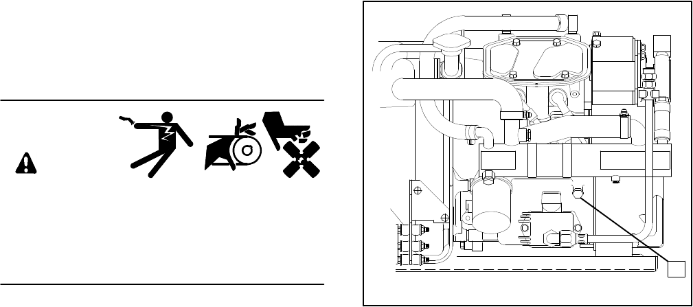
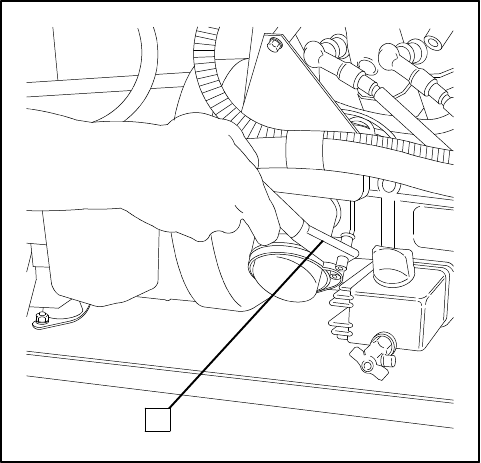
Low Oil PressureShutdownSwitch
The lowoil pressureshutdownswitch protectsthe
engineagainstinternaldamage,iftheoilpressuredrops
below20psi(138kPa),duetoanengineoilpumpfailure
orotherengine malfunction.The location of the lowoil
pressureshutdownswitchis showninFigure 2-2.
NOTE
The lowoil pressureshutdownswitch doesnotactasa
lowoil levelswitch.The onlywayto protectagainst
engine damage due tolowoil level istocheck the oil
levelregularly.
1
258000-D
1.LowOil PressureShutdownSwitch
Figure 2-2.Low Oil PressureShutdownSwitch
TP-5695 12/93 Operation 2-5
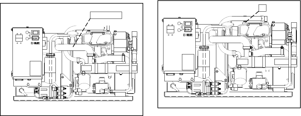
High WaterTemperature
ShutdownSwitch
The high watertemperatureshutdownswitch protects
the engine againstinternaldamage if the cooling water
temperatureinthe engine block istoo high due to
cooling waterorcoolantcirculation problems.The
switchis set totrip at248--266°F(120--130°C).The
location of the high watertemperatureshutdownswitch
is showninFigure 2-3.
TOTALHOURS
00 000 1/10
10A
FUSE
STARTSTOP
BATT.
CHRG.
INPUT
258000-D
1(hidden)
1.High WaterTemperatureShutdownSwitch
Figure 2-3.High WaterTemperature
ShutdownSwitch
High ExhaustTemperature
ShutdownSwitches
The two high exhaust temperatureshutdownswitches
protect the engine againstinternaldamage due to
excessive exhaust temperatures.The switchesareset
at210--220°F(99--105°C).The locationsof the high
exhaust temperatureshutdownswitchesareshownin
Figure 2-4.
TOTALHOURS
00 000 1/10
10A
FUSE
STARTSTOP
BATT.
CHRG.
INPUT
258000-D
1
1.High ExhaustTemperatureShutdownSwitches
(one located on eachmanifold)
Figure 2-4.High ExhaustTemperature
ShutdownSwitches
TP-5695 12/932-6Operation
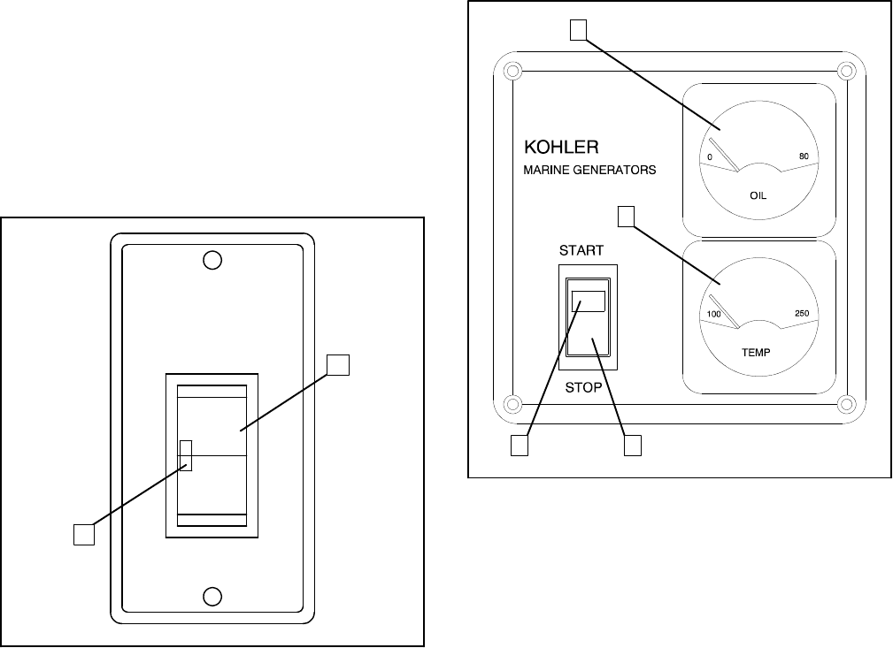
RemotePanels(Optional)
RemoteStartPanel
Remotestartpanelallows starting-stopping froma
locationremoteofthegeneratorset.Generatorsetsare
equippedwitha6-pinconnectoron controllerbottomfor
connection of the kit. See Figure 2-5.
2
1
1.“ON”Light2.Start/Stop Switch1-656
KOHLER
GENERATOR
START
STOP
Figure 2-5.RemotePanelFeatures
RemoteStartand
Two-MeterPanelKit
Allows starting-stopping fromalocation remote of the
generatorset. The illuminated gaugesinclude an
engine oil pressure gauge and a watertemperature
gauge.Generatorsets come equipped with a 6-pin
connectoron controllerbottomforconnection of the kit.
See Figure 2-6for remotestartand meterpanelkit.
1
2
4 3
1.Engine Oil Pressure
2.WaterTemperature3.Start/Stop Switch
4.“On”Light
1-762
Figure 2-6.RemoteStartand Two-Meter
PanelFeatures
Start/Stop Switchisarocker-type switchwith“ON”
lightused tostartand stop generatorset.
EngineOil PressureGaugemeasuresengine oil
pressure.Normalengine operating range is30--50 psi
(207--345 kPa).
NOTE
During the engine break-in period,itisnormalforthe
engine to produce higheroil pressurereadings.
WaterTemperatureGaugemeasuresengine coolant
temperature.Normalengine operating range is
170--195_ F(77--91_ C).
TP-5695 12/93 Operation 2-7
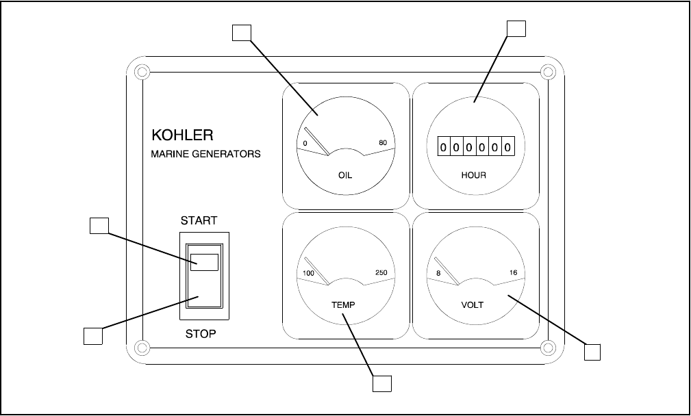
RemoteStartand Four-Meter
PanelKit
Allows starting-stopping fromalocation remote of the
generatorset. The illuminated gaugesinclude a DC
voltmeter,engine oil pressure gauge,water
temperature gauge,and generator running time
hourmeter.Generatorsets come equipped with a 6-pin
connectoron controllerbottomforconnection of the kit.
See Figure 2-7for remotestartand four-meterpanel
features.
Start/Stop Switchisarocker-type switchwith“ON”
lightused tostartand stop the generatorset.
DC Voltmetermeasures voltage ofstarting battery(ies).
Normalbatteryoperating range is12--14 volts.
EngineOil PressureGaugemeasuresengine oil
pressure.Normalengine operating range is30--50 psi
(207--345 kPa).
NOTE
During the engine break-in period,itisnormalforthe
engine to produce higheroil pressurereadings.
WaterTemperatureGaugemeasuresengine coolant
temperature.Normalengine operating range is
170--195_ F(77--91_ C).
Hourmeterrecordstotalgeneratorsetoperating hours
for referenceinmaintenancescheduling.
12
6
53
4
1.Engine Oil Pressure
2.Hourmeter
3.Voltmeter
4.WaterTemperature
5.Start/Stop Switch
6.“ON”Light
1-830
Figure 2-7.RemoteStartand Four-MeterFeatures
TP-5695 12/93 Scheduled Maintenance 3-1
Section 3.ScheduledMaintenance
Usethe following serviceschedule and the hourmeter
on the controllertoscheduleroutine maintenance. In
addition tothe routine serviceslisted inthismanual,
there are otherimportantstepsthatshould be taken to
keep a generatorsetintop condition.Usuallytoolsand
instrumentsrequired forthese additionalstepsare not
availabletothegeneratorsetowner.Forthisreason,the
setshouldbereturned periodicallyto an authorized
service dealer/distributorforcompleteservicing and
tune-up.The benefitsofsuchservicewill be improved
performance and continuous satisfactoryoperation
duringalongtrouble-freeservicelife.UsetheOperating
HourServiceLoginthebackofthismanualtodocument
servicesperformed.
Serviceintervalsarelocated on the top rowsof the
ServiceSchedulechart. It indicateshowoften
maintenancetasks need to be done.Eachserviceitem
istoberepeated at the specified interval.Forexample,
an itemrequired at50 hourswill again need to be
performed at100 hours,150 hours,etc.
Forcontinuedsatisfactoryoperationandlongevityofthe
engine and generatorset, propermaintenance and
eventualoverhaulbyacompetentmechanic/technician
are essential.Whileitisnotpossibleto anticipate
component failure,rough operation,metallicnoises,
and excessive oil loss are among the indicatorsof
potentialproblems.Do notignoretheseconditions!
NOTE
Operatethe generatorsetwithload applied atleast
onceamonth.Allowgeneratorsettorunaboutonehour
toreach operating temperature.Thispreventsthe
formation ofcorrosion on internalengine components
when exposed tothe breakdown ofexhaustgasesand
seawaterforlongperiodsofgeneratorinactivity.Ifunitis
to be outofserviceforseveralmonths,see Storage
Procedure.
WARNING
Accidentalstarting.
Cancause severeinjuryordeath.
Disconnectbattery cablesbeforeworking on
generatorset(negativelead firstand reconnectit
last).
Accidentalstarting cancause severeinjuryor
death.Disconnectbattery cables(remove negative
lead firstand reconnectitlast)to disable generatorset
beforeworking on anyequipmentconnected to
generator.The generatorsetcan be started byremote
start/stop switch unless thisprecaution isfollowed.
NOTE
HARDWAREDAMAGE!Engine and generatormake
useofbothAmericanStandardandmetrichardware.Be
sureto usethe correctsizetoolsto preventrounding of
boltheadsand nuts.
NOTE
High-mineralcontentseawater (saltwater) can cause
rapid destruction ofmetals.Wipe up all saltwater
spillage on and around generatorsetand keep metal
surfacesfree fromaccumulated saltdeposits.

TP-5695 12/933-2Scheduled Maintenance
Service Schedule
Before
Starting
After20
Hrs.or
One
Month
Every 50
Hrs.or3
Months
Every
100 Hrs.
or6
Months
Every
200 Hrs.
orYearly
Every
300 Hrs.
or2Years
LUBRICATIONSYSTEM
Check oil levelX
Change oil X(Break-in
Period)X
Change oil filterX
FUELSYSTEM
Check the fuel levelX
Fill fueltankX
Lubricatecarburetorand choke
linkage X(Break-in
Period)X
Clean fuelscreen X
Servicefuel linesX
IGNITIONSYSTEM
ReplacesparkplugsX
COOLINGSYSTEM
Check coolantlevelX
Check seawateroutletX(During
Operation)
Inspectexhaustsystem
componentsforcracks and
corrosion (exhaustmanifold,
mixing elbow,exhaustline,
hoseclamps,silencer,and
outlet flapper)
X X
Check function ofsiphon break
(ifequipped)X
Check condition ofheat
exchangeranticorrosion zincX(100 Hrs.
or3
Months)
Replace heatexchanger
anticorrosion zincX
Replacethe impellerof
seawaterpumpX
Check thermostat function X
INTAKE/EXHAUSTSYSTEM
Check exhaustgas condition X(During
Operation)
Clean the exhaust/watermixing
elbowX
Clean airfilterelementX

TP-5695 12/93 Scheduled Maintenance 3-3
Service Schedule(Continued)
Before
Starting
After20
Hrs.or
One
Month
Every 50
Hrs.or3
Months
Every
100 Hrs.
or6
Months
Every
200 Hrs.
orYearly
Every
300 Hrs.
or2Years
ELECTRICALSYSTEM
Check electrolytelevel
(Batterieswithfillercapsonly)X X
Check and tighten electrical
connectionsX
Check specificgravity
(Batterieswithfillercapsonly)X
Clean battery cablesX
ENGINEAND MOUNTING
Check forleakage ofwater, fuel,
oroil X X
Lubricate governorlinkage X(Break-in
Period)X
Retighten all majornutsand
boltsX(Break-in
Period)X
Check and tighten mounting
boltsand vibromountsX
Check intake/exhaust
valveclearanceX
REMOTECONTROLSYSTEM,
ETC.
Check compartmentcondition
(fuel,oil,orwaterleaks)X
Check the remotecontrol
operation X(Break-in
Period)
Testrun generatorsetX
(Monthly)
GENERATOR
BlowdustoutofgeneratorX
TP-5695 12/933-4Scheduled Maintenance
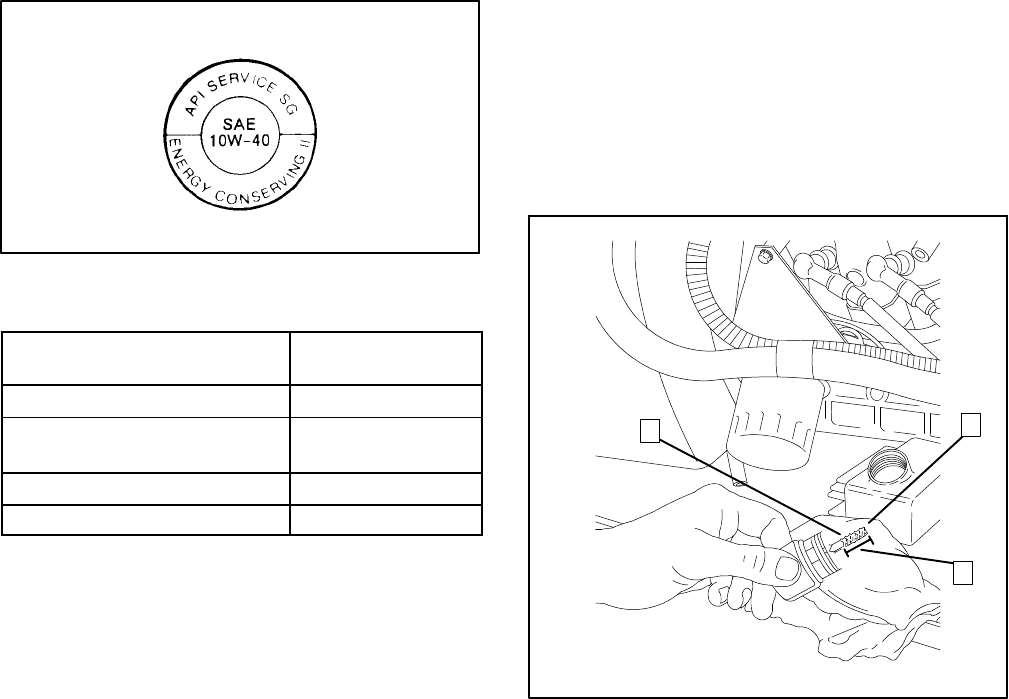
Lubrication System
Specifications
Use high qualitydetergentoil ofAPI(American
PetroleumInstitute)serviceclassSF,SF/CC,orSF/CD.
Thisinformation can be found on mostoil containers,
see Figure 3-1.The symbol illustrated identifiesthe API
serviceclass inthe upperportion.The centerindicates
the SAE (SocietyofAutomotiveEngineers)viscosity
grade.The bottomportion (when used)signifiesthe oil
isintended toimprovefueleconomyand displays the
phrase“EnergyConserving.” Selectviscositybased on
the airtemperature at the time ofoperation.(See
Figure 3-2.)
SAE 10W40 isthe preferred oil forgeneralusewhere
temperaturespermit.
1--792
Figure 3-1.Oil Service Class and
SAE ViscosityGradeSymbol
WhenOutsideTemperature
isConsistently:Use SAE
ViscosityGrade:
Below5_ F(--15_ C)5W30
--5_ F(--21_ C)to
90_ F(32_ C)10W30
Above 15_ F(--10_ C)20W40 or20W50
Above--5_ F(--21_ C)10W40 (Preferred)
Figure 3-2.RecommendedSAE
ViscosityGrades
Using otherthan the appropriateserviceclass oil or
extended oil change intervals couldcause engine
damage whichisnotcovered bythe engine warranty.
Do notmixoilsofdifferentviscosities. It isalso bestnot
tomixdifferentbrandsofoils.Possibleincompatibility
couldcauseabreakdown oflubricating ingredientsand
reduce engine protection.
Oil Check
Checkoillevelincrankcasedailyorbefore eachstartup
toinsurethat the level isinthe saferange.
NOTE
Do notcheck oil levelwhen unitisrunning.Generator
setmustbe stopped and levelto getan accurate
reading.
If generatorsethasjustbeen run,allowafewminutes
forthe oil toreturntothe oil pan beforechecking level.
Tocheck oil level,remove dipstick and wipe the end
clean,place bottomthread ofdipstick againstoil fill hole
and remove.Do notscrewin dipstick when checking oil
level.Levelshould be between MINand MAX marks on
dipstick.See Figure 3-3.
NOTE
Do notoperatethe setif the level isbelowthe MINmark
orabovethe MAX mark.Oil abovethe MAX markis
wasted due toincreased oil consumption.
12
3
1.MAX Limit
2.MINLimit3.SafeRange
1-826
Figure 3-3.Checking Oil Level
TP-5695 12/93 Scheduled Maintenance 3-5
Adding Oil
It isnormalto add some oil between oil changes.The
amountwillvarywiththe usage.Openfillcap and poura
small amountofoil using a funnelorothersuitable
pouring device.See Figure 3-4.Waitafewminutesand
check level. If necessary,add more oil and then check
again.Eachtime be sureto add small quantitiesand
check to preventoverfilling.
1-826
Figure 3-4.Adding Oil
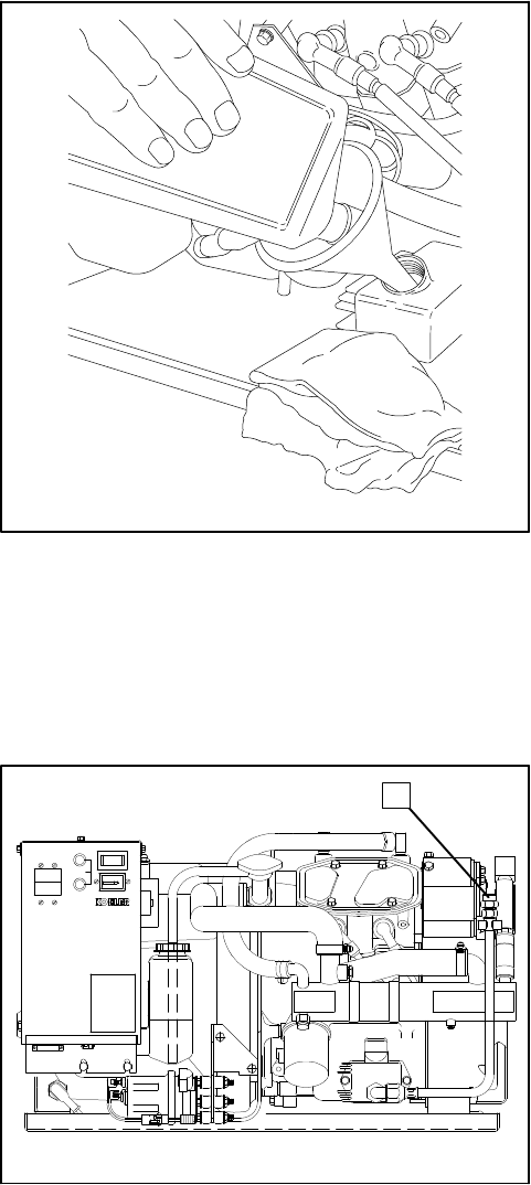
Oil Change/Oil FilterChange
Change oil and oil filterevery200 hoursoryearly.
Change oil morefrequentlyunderdirty,dusty
conditions.Changeoilwhiletheengineisstillwarm.See
Figure 3-5 and usethe following procedure.
TOTALHOURS
00 000 1/10
10A
FUSE
STARTSTOP
BATT.
CHRG.
INPUT
1
258000-D
1.Oil DrainCap
Figure 3-5.Oil DrainCap
1.Place oil drain hosein a propercontainer.Remove
oil draincap.Ifa drain pumpisused,remove oil
draincapand connectoildrainhoseto drainpump.
2.Allowampletimeforall oil to drainintocontainer. If
drain pumpisused,activate pump until oil is
removed.
3.Loosen oil filterbyturning in a counterclockwise
direction.Oil filteris2 1/2in.(64 mm)dia.with 14
flutes.Use oil filterwrench,ifnecessary.See
Figure 3-6.Useragsto handle hotoil filterand
clean up spilled oil.Removefilterfromoil filter
adapteron engine and discard oil filterin a proper
container.
4.Clean contactsurface ofoil filteradapter.
5.Lightlylubricatethe gasketsurface ofnewoil filter
withfresh engine oil.Thread oil filteronto oil filter
adapteruntil gasketmakes contact; then
hand-tighten oil filteran additional3/4turn.
NOTE
If an automaticoil drain/oil fill pumpisused,omit
Step 6.Fill with properamountand type ofoil,see
Step 6.When complete,replacecap and
disconnectpump.
6.Replace oil draincap.Remove oil fill cap.Add oil
usingafunnelorothersuitablepouringdevice.See
Specifications—Engine foroil capacityand
Lubrication System—Specificationsforproper
serviceclass and SAE viscosityofoil.Replace oil
fill cap.
7.Startgeneratorsetand check forleaks atoil drain
cap and oil filter.
8.Stop generatorset. Waitafewminutesforoil to
returnto oil pan.Remove dipstick and wipe clean,
reinsertasfaraspossible and removetocheck oil
level.Add oil,asnecessary, to bring levelup to
MAX mark.
TP-5695 12/933-6Scheduled Maintenance
11-826
1.Oil FilterWrench21/2in.(64 mm)Dia.
Figure 3-6.Removing Oil Filter
FuelSystem
Specifications
Forbestresults,use only clean fresh,regulargrade
unleaded gasoline.Usefuelwith a minimumoctane
rating asdesignated bythe following:
Antiknock Index(Average ofResearch 86
Octane Numberand MotorOctane Number)
Unleaded fuel isrecommended sinceitleavesless
combustion chamberdeposits.Oil mustnotbe mixed
withfuel.
If using a gasolinecontaining alcohol(gasohol),be sure
the octane rating isatleast86 (Antiknock Index).There
aretwotypesofgasohol:one containing ethanol,and
anothercontaining methanol.
Do notuse gasoholthatcontainsmorethan 10%
ethanol.Do notuse gasoholcontaining methanol
(methylorwood alcohol)thatdoesnotalsocontain
cosolventsand corrosion inhibitorsformethanol.Never
usegasoline containingmorethan5%methanol,evenif
ithas cosolventsand corrosion inhibitors.
NOTE
Fuelsystemdamage and engine performance
problemsresulting fromthe use ofsuchfuelsare not
coveredunderWarranty.Hondacannotendorsetheuse
offuelscontainingmethanolsinceevidenceofsuitability
isas yetincomplete.Before purchasing fuelfroman
unfamiliarstation, trytoconfirmwhetherthe fuel
containsalcohol,and towhatpercentage.Ifany
undesirableoperating symptomsarenoticedafterusing
a gasoline thatcontainsalcohol,orone thatcontains
alcohol,switchto a gasoline thatdoesnotcontain
alcohol.
NOTE
Discontinue use ofanygasoholoralcohol/gasoline
blend ifengine performance orfuelsystemproblems
occur.Do notusesuchfuelunless itisUNLEADED.
Usefreshgasoline toensureitisblendedforthe season
and to prevent the formation ofgumdepositswhich
couldclog the fuelsystem.Do notuse gasoline left over
fromthe previous season.
TP-5695 12/93 Scheduled Maintenance 3-7
FuelPumpScreen
WARNING
Explosive fuelvapors.
Cancause severeinjuryordeath.
Useextremecarewhen handling,storing,
and using fuels.
Explosive fuelvapors cancause severeinjuryor
death.Allfuelsarehighlyexplosiveinavaporstate.Use
extremecarewhen handling,storing,and using fuels.
Storefuel inawell-ventilated area awayfrom
spark-producing equipmentand outof the reach of
children.Neveradd fueltothe tankwhilethe engine is
running sincespilled fuelmayignite on contactwith hot
partsorfromignition spark.Do notsmoke orpermit
flame orsparkto occurnearpotentialsourcesofspilled
fuelorfuelvapors.Keepfuellinesand connectionstight
and in good condition—don’treplaceflexiblefuel lines
withrigidlines.Flexiblesectionsare used to avoid
breakage due tovibration.Should anyfuel leakage,fuel
accumulation,orelectricalsparks be noted,DONOT
OPERATEGENERATORSET.Havesystemsrepaired
beforeresuming generatoroperation.
Gasoline—Store gasoline onlyin approved red
containers clearlymarked GASOLINE.Do notstore
gasoline in anyoccupied building.
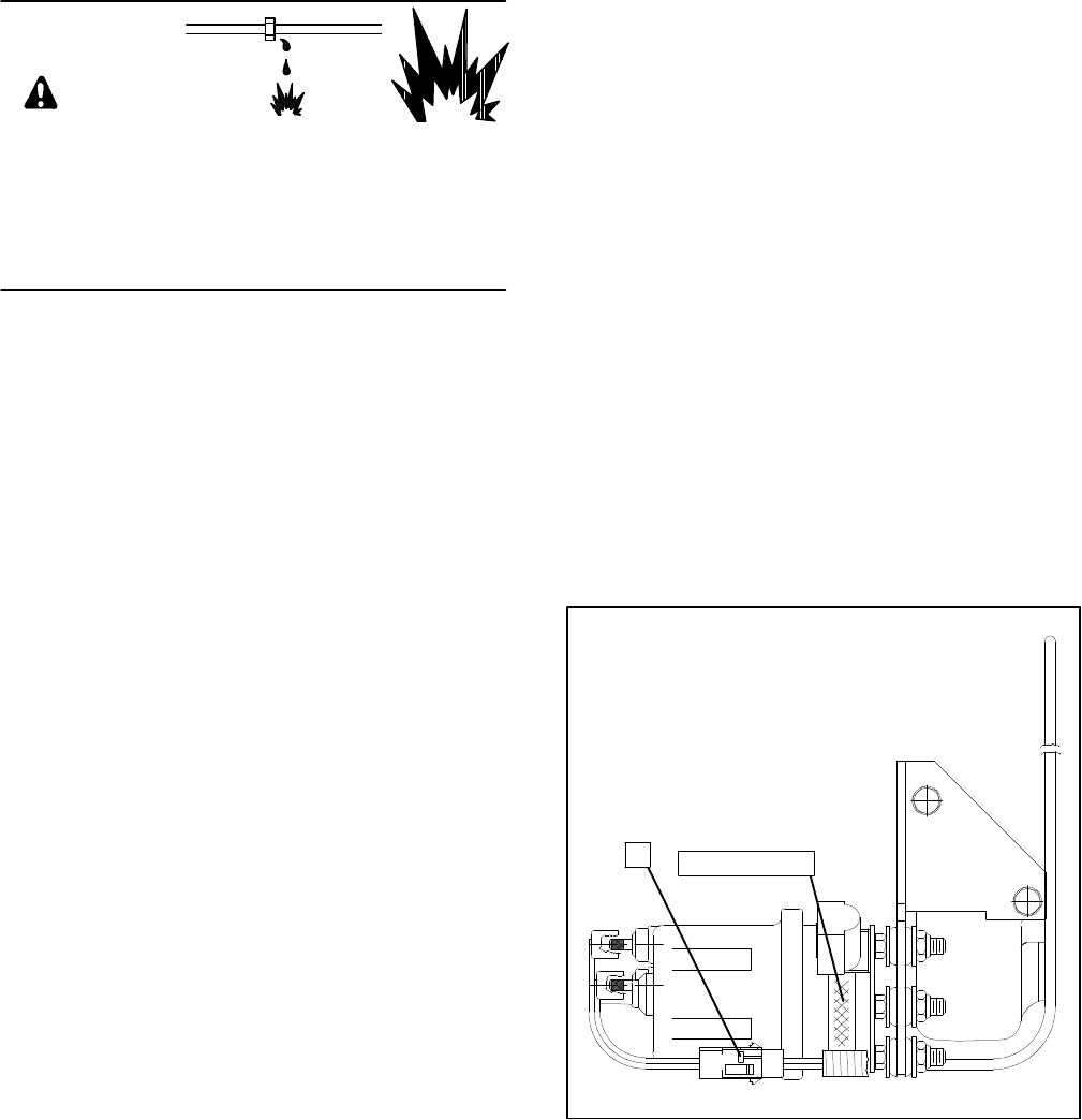
The electricfuelpumpincludesascreen.(See
Figure 3-7.)At the recommended intervalorwhen
clogging is suspected,inspectand clean the screen as
follows:
1.Shutoff fuelflowto electricfuelpump at tankorat
in-line shutoff valve.Disconnectharness plug (see
Figure 3-7forlocation).
2.Disconnect fuel linesfromelectricfuelpump,
drainingfuelfromthelinesandpumpintoasuitable
containerto preventspillage intothe bilge.
3.Removethe three nutsthatsecurethe electricfuel
pumptothe mounting bracket.
4.Removethe three mounting studsfromtheelectric
fuelpump.
5.Removethe coverplate and inspect the screen.
Remove anydebrisor residue.Besurethe screen
isintact. If the screen isdamaged,replacethe fuel
pump.
6.Check the O-ring seal.Replacethe O-ring ifitis
nicked oreroded.
7.Reinstall the coverplate and secureit tothe fuel
pump byreinstalling the three mounting studs.
8. Insert the three mounting studson the fuelpump
through the mating holesinthe mounting bracket.
Reinstall the three nutstosecurethe fuelpumpin
place.
9.Reconnect the fuel linestothe fuelpump.
10.Open fuel line at tankorin-line shutoff valve and
check forleaks fromthe fuelpump at fuel line
connectionsand coverplate.
258000-D
2(enclosed)
1.Harness Plug 2.FuelPumpScreen
1
Figure 3-7.FuelPumpScreen
TP-5695 12/933-8Scheduled Maintenance
Carburetor/Choke Lubrication
Theonlymaintenancerequiredistolubricatecarburetor
and chokelinkage at the specified intervalusing white
lithiumgrease orlubriplate.
CarburetorAdjustments
The carburetorisasingle-barrel,horizontaldesign and
usesan electric choke.
Lack ofpowerusuallyindicatesthat the fuelmixtureis
too rich.An overrichmixturemayalso be caused bya
clogged airintake(backfireflame arrestor)—check this
beforereadjusting carburetor.Fuelmixturemaybe too
lean ifengine skipsorbackfires.Minorcarburetor
adjustmentmaybe necessarytocompensatefor
differencesin altitude, fuel,and temperature.
1.WithENGINE STOPPED, turnfuelmixturescrew
in(clockwise)until itseatslightly.DONOT
FORCE!Turnfuelmixturescrewout2to
2 1/2turns.See Figure 3-8.
2.Startengine and letitrun atno load forabout5
minutes.Beforemaking adjustmentsengine
shouldbethoroughlywarmed up running at
governed speed,and connected tofull load.
3.Turnlowspeed mixturescrewin until engine
instability(hunting)developsand then screwout
until engine instabilityisagain apparent. Turn
screwbackin untilitispositioned halfwaybetween
the pointsofincreasing stability.When properly
adjusted,engine will operatewithsteadygovernor
action.
4.To adjusttheidlespeed,runthegeneratorsetatno
load.Pushthe throttlelevercounterclockwise until
ithitsthe idlespeed screw.Holding the throttle
leveragainstthescrew,adjusttheidlespeedscrew
untilunitrunsat55Hz(3300rpm)for60Hzmodels
or45 Hz(2700 rpm)for50 Hzmodels.
NOTE
If engine runspoorlyafteradjusting carburetorand
doing scheduled maintenance,return generator
set to an authorized service dealer/distributorto
have problemcorrected.
WARNING
Fire.
Cancause severeinjuryordeath.
Do notsmoke orpermit flame orsparkto occur
nearfuelorfuelsystem.
Asuddenflashfirecancausesevereinjuryordeath.
Donotsmokeorpermitflameorsparktooccurnearfuel
system.Keepthecompartmentandgeneratorsetclean
and free ofdebristominimizechancesof fire.Wipe up
all spilled fueland engine oil.
2
1
3
1.GovernorArm
2.LowSpeed
MixtureScrew
3. IdleSpeed Screw
1-829
1-829
Figure 3-8.FuelMixtureAdjustment
TP-5695 12/93 Scheduled Maintenance 3-9
Ignition System
Ignition SystemService
The ignition systemistransistorized and breakerless.
Undernormalconditions,onlythe sparkplugsneed
serviceonaregularbasis.The electronicignition
modulerequiresno maintenance and should giveyears
of trouble-free service.Ifamodule problemis
suspected,haveservice performed byan authorized
service dealer/distributor.
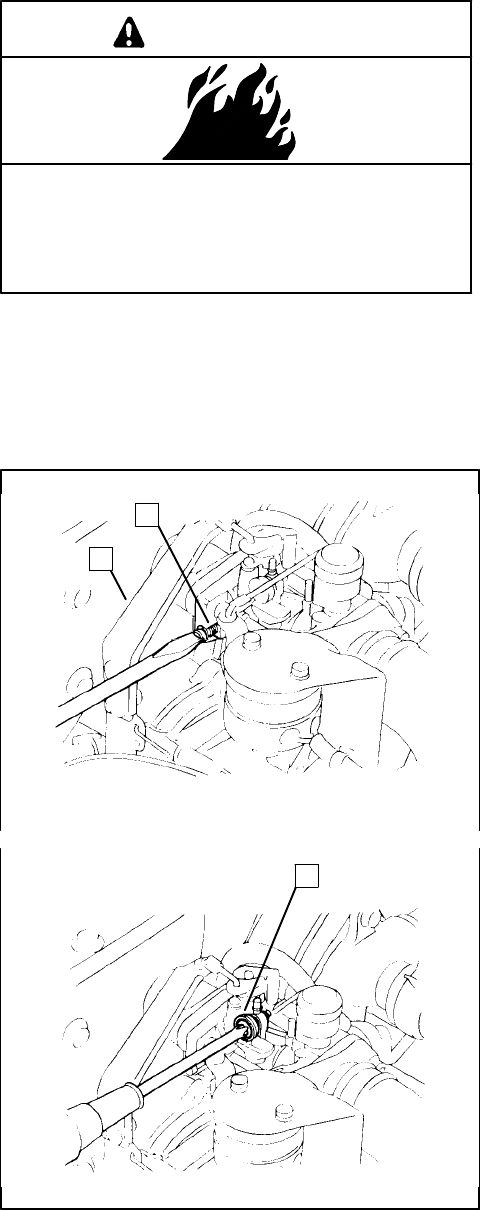
SparkPlugs
At the recommended interval(showninthe service
schedule)servicesparkplugs.
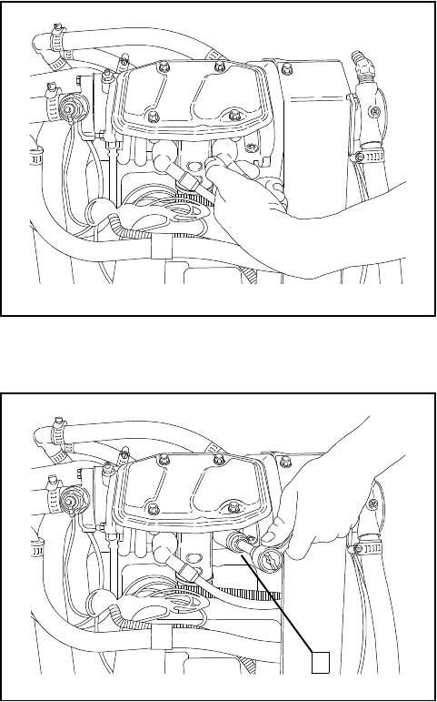
1.Removesparkplug wiresbygrasping bootand
turning slightlywhile pulling.Do notpull wire.See
Figure 3-9.
NOTE
Pullingwireratherthanbootmaycausedamageto
wire orterminal.
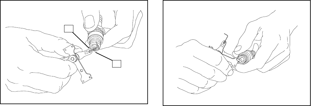
2.Wherepossible,usecompressed airtoremovedirt
fromaround eachsparkplug beforeremoval.This
procedurewillpreventdirtparticlesfromfallinginto
combustion chamber.Loosen sparkplug with a
ratchetandsparkplugsocketwitharubberinsertto
preventdamage tosparkplug.See Figure 3-10.
Removesparkplugsone atatime and examine.
See Figure 3-11 to evaluate engine conditionsby
color/condition ofsparkplugs.
3.Cleansparkplugsbywiping with a ragandthenfile
the centerelectrode sothatitisparalleltothe side
electrode.Shouldreplacementbe necessary,see
“Specifications”forsparkplug type.
NOTE
Do notsandblast, wire brush,scrape,orotherwise
servicesparkplug in poorcondition.Bestresults
are obtained with a newplug.
1-827
Figure 3-9.Removing SparkPlug Wires
11-827
1.13/16 in.SparkPlug Socket
Figure 3-10.Removing SparkPlug

TP-5695 12/933-10 Scheduled Maintenance
ProblemMeansofIdentification PossibleCause
NormalLight tan orgraydepositon the
firing tip.Good operating conditionsand
maintenance.
Gap bridgedDepositsbuilt-up and closing gap
between electrodes.Oil orcarbon fouling.Clean and
regap.
Oil fouledWetblack depositson the insulator
shell bore electrode.Excessive oil entering combustion
chamberthrough wornringsand
pistons,excessiveclearance
between valve guidesand stems,
orworn orloose bearings.
Replace plug.
Carbon fouledBlack,dryfluffy carbon deposits
on insulatortips,exposed shell
surfaces,and electrodes.
Using too coldrange plug,weak
ignition,clogged airintake or
impropercarburetoradjustments,
defectivefuelpump,overrichfuel
mixture,orexcessivenoload
operation.Clean and regap.
LeadfouledDarkgray,black,yellow,ortan
deposits;ora glazed coating on
the insulatortip.
Caused byhighlyleaded fuel.
Replace plug.
Pre-ignition Melted electrodesand possibly
blistered insulator.Metallicdeposits
on insulatorsuggestsinternal
engine damage.
Wrong type of fuel,incorrect timing
oradvance, too hotofa plug,burnt
valves,orengine overheating.
Replace and plug.
Overheating White orlightgrayinsulatorwith
small black orgray/brownspots
with bluish(burnt)appearance on
electrodes.
Engine overheating,wrong type of
fuel,loosesparkplugs, too hota
plug,lowfuelpump pressure or
incorrectignition timing.Replace
plug.
WornSeverelyeroded orworn
electrodes.Caused bynormalwearand failure
toreplace atproperinterval.
Replace plug.
Figure 3-11.SparkPlug Condition
4.Beforeinstalling any sparkplug,check the gap.
See Figure 3-12.The propergap isattained when
the feeler (orwire)gauge justpassesbetween the
sparkplug electrodes.Itshould pass easily,but
withsomeresistance ordrag.The correctgap is
0.028--0.031 in.(0.7--0.8mm).
5.Toreadjust the sparkplug gap,use gapping toolto
gentlybend the side electrode closerto orfurther
fromthe centerelectrode.See Figure 3-13.The
side electrode mustbe centered overthe center
electrode.
6.Being carefulnot to bumpthe electrode,hand
threadsparkplug clockwiseintocylinderheaduntil
resistanceisfelt.
7.Usingatorquewrench,tighteneachsparkplugtoa
torque of18--22 ft. lbs.(20--30 Nm).Ifatorque
wrenchisnotavailable,hand-tighten sparkplug
until resistanceisfeltand then use a ratchet
wrenchtotighten the plug an additional1/2turn(if
installing a newplug)or1/8--1/4turn(ifreinstalling
a used plug).DoNOTovertighten asthismay strip
threadsoralterelectrode gap setting.
8.Check sparkplug wireconnectorin boot for
accumulated dirt, grease,etc., and clean as
necessary.Firmlypushsparkplug connectorand
bootontosparkplug.
TP-5695 12/93 Scheduled Maintenance 3-11
1
2
1.0.028--0.031 in.
(0.7--0.8mm)Gap 2.SparkPlug Electrodes
1-514
Figure 3-12.Checking SparkPlug Gap
1-511
Figure 3-13.Adjusting SparkPlug Gap
TP-5695 12/933-12 Scheduled Maintenance
Cooling Systems—
Closed/HeatExchanger
Inaclosed cooling system, the seawaterdoesnot
circulatethrough the engine butcirculatesthrough
separatechamberswithinthe heatexchangertocool
the engine coolant. The seawateristhen mixed with
engine exhaustand ejected out the exhaustoutlet. The
coolantis circulated through cooling passagestocool
theengine.All modelsmakeuseofacoolant thermostat
andacoolantrecoverytank.Thecoolantcapacityofthe
engine with heatexchangeris0.72 U.S.qts.(0.68 L)for
all models.Asolution of50%ethylene glycoland 50%
clean,softened waterisrecommended toinhibit
rust/corrosion.Acoolantsolutionof50%ethyleneglycol
will provide freezing protection to--34°F(--37°C)and
overheating protection to 265°F(129°C).Acoolant
solution withless than 50%ethylene glycolmaynot
provide adequatefreezing and overheating protection.
Acoolantsolution withmorethan 50%ethylene glycol
can cause damage to engine and components.Do not
use alcoholormethanolantifreeze ormixthemwiththe
coolant.
Filling and Checking
WARNING
Hotcoolantand steam.
Cancause severeinjuryordeath.
Beforeremoving pressurecap stop generator,
allowtocooland loosen pressurecap torelieve
pressure.
Hotcoolantcancause severeinjuryordeath.Allow
engine tocooland release pressurefromcooling
systembefore opening pressurecap.Torelease
pressure,coverthe pressurecap with a thick cloththen
turnitslowly counterclockwisetothe firststop.After
pressure hasbeen completelyreleased and the engine
has cooled,removecap. If generatorsetisequipped
withacoolantrecoverytank,checkcoolantlevelattank.
NOTE
ENGINEDAMAGE!Failureto bleed airfromcooling
system may cause overheating and subsequent
damage to engine.
NOTE
Specialattention should be given when checking for
propercoolantlevel.Afterthecoolanthasbeendrained,
itnormallyrequires sometime beforecompleterefill of
the engine waterjacket takesplace.
Beforefilling the cooling system,verifythatall hose
clampsaretight. Loosen air-bleed screwlocated on top
of the engine to allowtrapped airto escape.See
Figure 3-14.Place a rag around the screwto prevent
coolantspillage ontothe block.Remove pressurecap
locatedonthetopoftheengine(seeFigure 3-15)andfill
withthe recommended coolantuntil level isjustbelow
overflowtube opening.Tighten air-bleed screw when
coolant, free ofairbubbles,startstoflow.Replace
pressurecap.Startgeneratorsetand allowtorun for
about20--30seconds.STOPgeneratorsetandrecheck
coolantlevelbyremoving pressurecap.Repeat
procedure,asnecessary,until coolantcan no longerbe
added.
Acoolantoverflowbottleisprovided.Fill bottletojust
belowthe MAX mark.See Figure 3-16.Maintain proper
coolantlevel incoolantoverflowbottle.The MINmark
indicatesfull when cold and the MAX markindicatesfull
when hot. Coolantlevelshould always be between
thesemarks.The coolantlevelcan be checked using
the overflowbottlemarkings,butitisrecommended to
periodicallyremovethecoolantpressurecap and check
coolantlevel.
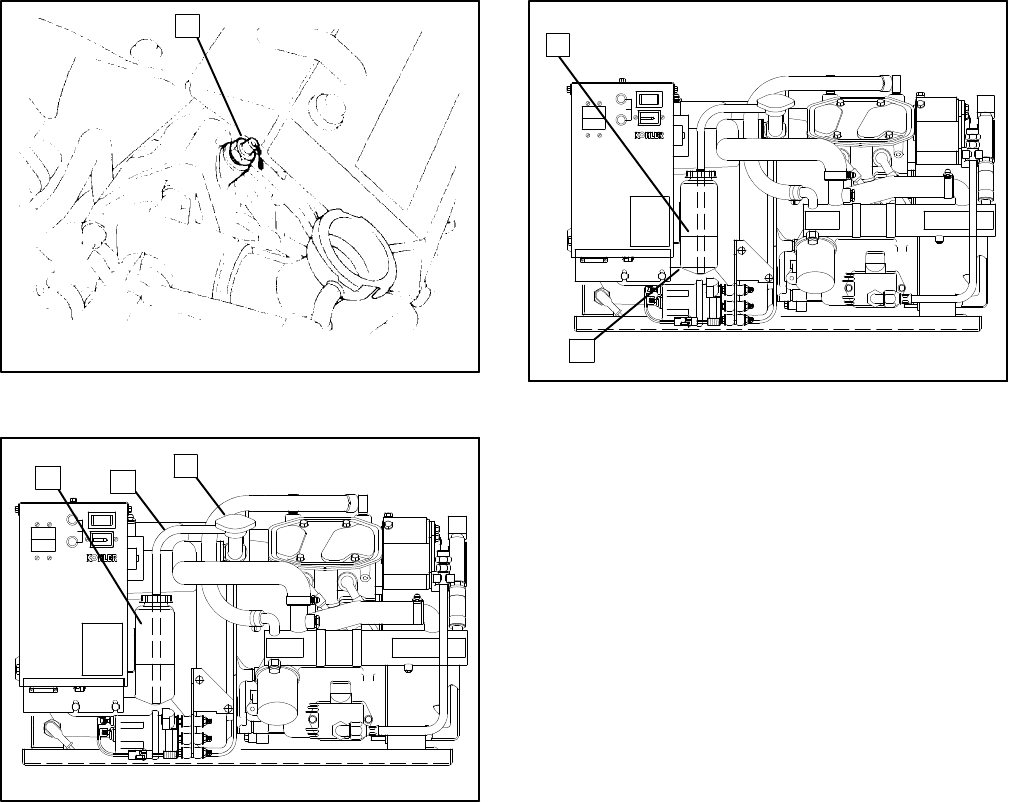
TP-5695 12/93 Scheduled Maintenance 3-13
1
1-828
1.Air-Bleed Screw;Use12mm Wrench
Figure 3-14.Air-BleedScrew
TOTALHOURS
00 000 1/10
10A
FUSE
STARTSTOP
BATT.
CHRG.
INPUT
3
2
1
1.CoolantRecoveryTank
2.Overflow Hose3.CoolantPressureCap
258000-D
Figure 3-15.CoolantPressureCap
TOTALHOURS
00 000 1/10
10A
FUSE
STARTSTOP
BATT.
CHRG.
INPUT
1
2
1.MAX.Mark2.MIN.Mark
258000-D
Figure 3-16.Checking CoolantLevel
TP-5695 12/933-14 Scheduled Maintenance
Flushing and Cleaning
If required, flushcoolant fromgeneratorset. To properly
flushcoolant, obtainKit#267999 and usethe following
procedure:
WARNING
Accidentalstarting.
Cancause severeinjuryordeath.
Disconnectbattery cablesbeforeworking on
generatorset(negativelead firstand reconnectit
last).
Accidentalstarting cancause severeinjuryor
death.Disconnectbattery cables(remove negative
lead firstand reconnectitlast)to disable generatorset
beforeworking on anyequipmentconnected to
generator.The generatorsetcan be started byremote
start/stop switch unless thisprecaution isfollowed.
WARNING
Hotcoolantand steam.
Cancause severeinjuryordeath.
Beforeremoving pressurecap stop generator,
allowtocooland loosen pressurecap torelieve
pressure.
Hotcoolantcancause severeinjuryordeath.Allow
engine tocooland release pressurefromcooling
systembefore opening pressurecap.Torelease
pressure,coverthe pressurecap with a thick cloththen
turnitslowly counterclockwisetothe firststop.After
pressure hasbeen completelyreleased and the engine
has cooled,removecap. If generatorsetisequipped
withacoolantrecoverytank,checkcoolantlevelattank.
1.Disconnect the battery,negativelead first.
2.With engine cooled,removethe air-bleed screw
and the high watertemperaturesafety shutdown
switchfromthe thermostathousing.
3.Connectkithosefittingstothe engine. Install kit
hosestofittings(ifnotalreadydone).
4.Connecta garden hosetothe femaleconnectorof
large kithose.Placethe free end of the small kit
hoseina1--2 gal.(min.)bucket.
NOTE
Heatexchangerpressurecap MUSTbe installed.
5.Turnonwatersupplytoflushcoolant fromengine
block.Turn off watersupplywhen clean wateris
observed coming fromhosein bucket.
6.Disconnectgardenhose.Placefreeendoflargekit
hoseintobucketandconnectanairhosetothefree
end of the smallerkithose.Applyairpressure(40
psi[276kPa]min.)until waterstopsflowingfromkit
hosein bucket. Thiswill remove about16 fl.oz.
(0.47 L)ofwaterfromengine block.
NOTE
Engine coolantcapacityis23 fl.oz.(0.68 L).
NOTE
Somesmall aircompressorsmaynotmaintain
pressure underthe required flowconditions. In
thesecases,itisrecommended that the end of the
kithoseinthe bucketbe closed off momentarily
until pressureisallowed to build up.Afterpressure
hasaccumulated,open end to allow watertoflow
into bucket. Repeatclosing and opening end ofkit
hose,asrequired.
7.Removekithoseswith hosefittingsfromengine.
8.Applypipe sealant tothreadsofhigh water
temperaturesafety shutdownswitch and install
switchinthermostathousing.Reconnectwiring
harness lead toswitch.
9.Applypipesealanttotheair-bleedscrewandinstall
screwinto engine.Do not finaltighten!
10.Removecap ofcoolantoverflowbottle and pour
contentsinto a suitablecontainer.Reinstall bottle
on unit.
11.Add freshcoolant tocoolantoverflowbottle.A
solution of50%ethylene glycoland 50%clean,
softened waterisrecommended toinhibitrust/
corrosion and provide freezing protection.Fill to
MINmark. Install coolantoverflowbottlecap.
12.Remove heatexchangerpressurecap and add
about5fl.oz.(0.15 L)ofclean,softened water.
Then fill remainderofengine withstraightcoolant
(100%)until level isjustbelowthe overflowtube
opening.Finaltighten the air-bleed screw when
coolant,free ofairbubbles,startstoflow.Installthe
heatexchangerpressurecap.
TP-5695 12/93 Scheduled Maintenance 3-15
13.Reconnectbattery,negativelead last.
14.Startgeneratorsetand allowthe set torun for
about20--30 seconds.Stop generatorsetand
recheck coolantlevelbyremoving heatexchanger
pressurecap.Add straightcoolant, ifnecessary,
until level isjustbelowthe overflowtube opening,
then reinstall pressurecap.Repeat this step until
coolantcan no longerbe added.Thisprocedure
should give an approximatemixture of50%
ethylene glycoland 50%water.
15.Wipe up spilled coolantand waterwithrags.
Dispose ofragsinapropercontainer.
16.Testrun generatorset forabout fiveminutesand
check forcoolantleaks.Thiswill allowthe coolant
mixturetomix completely.Stop generatorset.
17.Rinsecoolantflushkithosesandfittingswithclean
water.Storekit forfuture use.
18.Dispose ofused coolantinapropermanner.Do
NOTpollutewaterways!

TP-5695 12/933-16 Scheduled Maintenance
Anticorrosion Zinc
An anticorrosion zincanode isinstalled inthe heat
exchangertopreventelectrolyticcorrosionbyseawater.
When differentmetals,such asiron and copper,are
placed in a highly conductiveliquid(seawater), the iron
graduallyrusts.The zinchas chemicalpropertieswhich
causethe seawatertoreact toitratherthan the engine
components.
The anticorrosion zincanode shouldbechecked every
100 hoursorthree monthsand replaced every200
hoursoryearly.Depending upon operating conditions
and seawaterproperties, the anticorrosion zincanode
mayhavetobereplaced morefrequently.See
Figure 3-17 and usethe following procedure.
TOTALHOURS
00 000 1/10
10A
FUSE
STARTSTOP
BATT.
CHRG.
INPUT
1.HeatExchanger2.Anticorrosion Zinc
21258000-D
Figure 3-17.Removing Anticorrosion Zinc
1.With generatorsetcooled,drainthe cooling
seawatersystem.Closeseacock,remove
anticorrosion zincanode fromheatexchanger.
2.Useawire brushtoremovethe loosecorrosion on
the anticorrosion zincanode.Replacethe anode
when less than 50%of the 11/32 in.(9mm)dia.by
9/16 in.(14 mm)long portion ofzincremains.
3.Clean threaded hole ofheatexchangerand coat
threadsofanticorrosion zincanode with pipe
sealant(suitableformarine applications). Install
anticorrosion zincanode into heatexchanger.
4.Open seacock.Startgeneratorsetand check for
leaks at the anticorrosion zincanode location.
Check forseawaterflowbyobserving water
discharge fromexhaustoutlet.
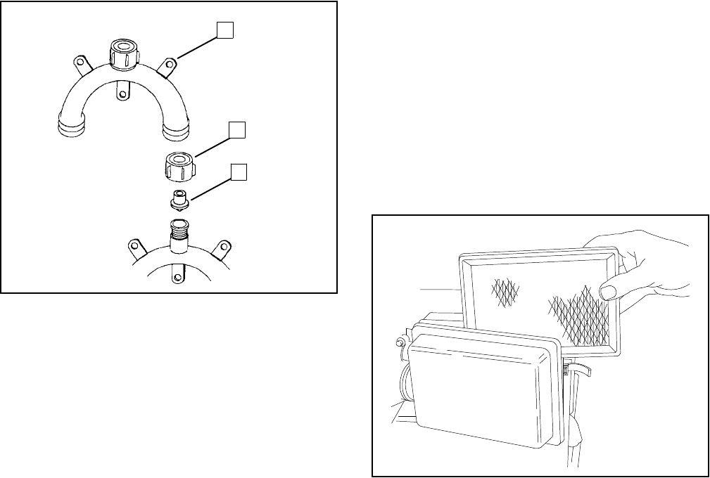
TP-5695 12/93 Scheduled Maintenance 3-17
PressureCap
Closed-loop cooling systemsincorporate a pressurized
captoraisetheboilingpointofthecoolantandmakeuse
ofhigheroperating temperatures. If leakage or
malfunction occurs,replacethe pressurized cap with
one supplied byKohlerCo.partnumber229958.
1
2
3
1.Mounting Base
2.Retaining Cap 3.Reed ValveAssembly
1-779
Figure 3-18.Siphon Break
Siphon Break
An optionalsiphon breakisused to preventseawater
entryintothe engine when the generatorsetis shut
down.Corrosionbuildup maynotallowthesiphonbreak
tofunctionproperly.Therefore,ifused,the siphonbreak
mustbe inspected and cleaned periodically.
NOTE
To preventsiphoning ofseawater,run the generator
while performing thisinspection.
Removetheretainingcap toinspect the reed valve.See
Figure 3-18.Clean the reed valvetoremoveresidue
and oxidation.Check that the reed valve(opening)is
clear.Replacethe siphon breakif the materialhas
hardened ordeteriorated. Install the reed valvewiththe
valvedownwardintothemountingbase.Installretaining
cap and tighten finger-tightonly.DoNOTovertighten.
AirCleanerand
Mixing Elbow
Servicing AirCleaner
The engine isequipped with a dry-type aircleaner.
Every50 hours(more often ifoperating underdustyor
dirtyconditions) removeelementandservicebytapping
elementlightlyagainst flatsurfaceto dislodge loose
surface dirt. Do notclean in anyliquid orblowoutwith
compressedairasthiswillruinfiltermaterial inelement.
Service aircleaneraftereach 50 hoursofoperation. If
dirty,bent, ordamaged replace elementwith genuine
Kohler replacement. See Figure 3-19.
1-905
Figure 3-19.AirCleanerService
Servicing Mixing Elbow
The mixing elbowcombineshigh temperature exhaust
and cooling seawater.Theseconditionsareconducive
torapid deterioration and,combined with engine
vibrations,prematurefailuresifnotproperlymaintained.
Check the mixing elbowforcarbon buildup and
corrosion inside the pipe.Clean or replacethe mixing
elbowasnecessary. Inspect the exhaustmanifold
mounting threadsforcracking and corrosion.
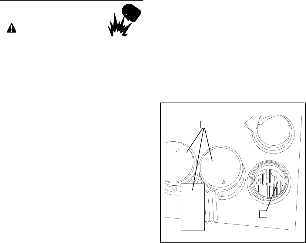
TP-5695 12/933-18 Scheduled Maintenance
Battery
The starting battery should be a 12-voltunitwith a
minimum250 CCA(coldcranking Amps)at0_ F(--18_
C).When usingamaintenance-free batteryitisnot
necessarytocheck the specificgravityorelectrolyte
level.Otherwise, these procedures should be done at
the intervals specified inthe ServiceSchedule.
WARNING
Sulfuric acidin batteries.
Cancause severeinjuryordeath.
Use protective gogglesand clothes.Can cause
permanentdamage to eyes,burnskin,and eatholes
inclothing.
Sulfuric acidin batteries cancause severeinjuryor
death.Sulfuricacidin battery can cause permanent
damage to eyes,burnskin,and eatholesinclothing.
Alwayswearsplash-proofsafetygoggleswhenworking
around the battery.Ifbatteryelectrolyteis splashed in
the eyesoron skin,immediatelyflushthe affected area
for15minuteswithlarge quantitiesofclean water.Inthe
caseofeyecontact,seekimmediatemedicalaid.Never
addacidtoabatteryoncethebatteryhasbeenplacedin
service.Doing somayresultin hazardous spattering of
electrolyte.
Explosion cancause severeinjuryordeath.Battery
gases can cause an explosion.Do notsmoke orpermit
flame orsparkto occurneara batteryatanytime,
particularlywhen itisbeing charged.Avoidcontacting
terminalswithtools,etc.topreventburnsand to prevent
sparks thatcouldcause an explosion.Remove
wristwatch,rings,andanyotherjewelrybeforehandling
battery.Neverconnectnegative(--) battery cableto
positive(+)connection terminalofstartersolenoid.Do
not testbattery condition by shorting terminalstogether
orsparks couldignite batterygasesorfuelvapors.Any
compartmentcontaining batteriesmustbe well
ventilated to preventaccumulation ofexplosive gases.
To avoidsparks,do notdisturb battery charger
connectionswhile batteryisbeing charged and always
turnchargeroff before disconnecting battery
connections.When disconnecting battery,remove
negativelead firstand reconnectitlast.
Cleaning
Keep battery clean bywiping itwith a dampcloth.Keep
all electricalconnectionsdryand tight. If corrosion is
present, disconnectcablesfrombatteryand remove
corrosion withawire brush.Clean batteryand cables
withasolution ofbaking soda and water.Becarefulthat
cleaning solution doesnotenterbattery cells.When
cleaningiscomplete,flushbatteryandcableswithclean
waterand wipe withadry cloth.Afterthe battery cables
arereconnected,coat terminalswith petroleumjelly,
silicon grease,orothernonconductive grease.
Checking ElectrolyteLevel
Check the levelofelectrolyte before eachstartup.
Removefillercapsand check tosee thatelectrolyte
level isup to bottomsof fillerholes,see Figure 3-20.
Refill asnecessarywith distilled waterorclean tap
water.DONOTadd fresh electrolyte!Then reinstalland
tighten fillercaps.Ifwaterisadded during freezing
temperatures,run generatorset20--30 minutesto allow
mixing ofadded waterand electrolyte.Thiswill prevent
damage to batterydue tofreezing.
1
2
1.FilterCaps2.Electrolyte Level
1-046
Figure 3-20.Checking ElectrolyteLevel
Checking SpecificGravity
Useabatteryhydrometertocheckthespecificgravityof
the electrolytein each battery cell.Correctactual
hydrometer readingsfortemperature. If the hydrometer
used doesnothaveacorrection table,usethe one in
Figure 3-21.The batteryisfully charged if the specific
gravityis1.260 atan electrolytetemperature of80_ F
(26.7_ C).The difference between specificgravitiesof
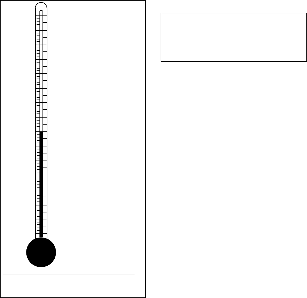
TP-5695 12/93 Scheduled Maintenance 3-19
eachcell should notexceed ±0.01.The battery should
be charged if the specificgravityisbelow1.215 atan
electrolytetemperature of80_ F(26.7_ C).
10
20
30
40
50
60
70
80
90
100
110
120
130
140
150
160
-- 12.2
-- 6.7
-- 1.1
4.4
10
21.1
26.7
32.2
37.8
43.3
48.9
54.4
60.0
65.6
71.1
15.6
+.032
+.030
+.028
+.026
+.024
+.022
+.020
+.018
+.016
+.014
+.012
+.010
+.008
+.006
+.004
+.002
0
-- .002
-- .004
--. 006
-- .008
-- .010
-- .012
-- .014
-- .016
-- .018
-- .020
-- .022
-- .024
-- .026
-- .028
°C°F
EXAMPLENO.1—
Temperaturebelow80°F(26.7°C)
HydrometerReading 1.250
Acid Temperature 20°F(--6.7°C)
Subtract.024 SpecificGravity
CorrectedSpecificGravityis 1.226
EXAMPLENO.2—
Temperature above 80°F(26.7°C)
HydrometerReading 1.235
Acid Temperature 100°F(37.8°C)
Add .008 SpecificGravity
CorrectedSpecificGravityis
1.243
The temperaturecorrection amountsto about.004 (4“points”)
ofspecificgravityforeach10°F(5.5°C)changeintemperature.
Correction
1-787
Figure 3-21.SpecificGravity
TemperatureCorrection
NOTE
Some batterytesters simplyhavefourorfive beadsin a
tube.Drawelectrolyteintothe tube.Useinstructions
withtester;otherwisesee the following chart.
FiveBeadsFloating—Overcharged
FourBeadsFloating—FullyCharged
Three BeadsFloating—AGood Charge
One orTwoBeadsFloating—ALow Charge
NoBeadsFloating—ADead Battery
Charging
Theenginebatterychargingcircuitwillprovide a charge
of12 voltsatup to 10 amps.
NOTE
If the batteryisused whilethe craft isdocked and the
generatorsetisnotrunningi.e.,auxiliarylights,two-way
radio,etc., the batterywill be drained and maynothave
enoughpowertostartthegeneratorsetlater.Therefore,
itmaybe necessarytoconnecta battery chargerwhile
the craft isdocked and running on shore power.
TP-5695 12/933-20 Scheduled Maintenance
Valve Adjustment
With overhead camengines,eachvalveis spring-held
inthe closed position until forced open bythe action of
the rockerarmincontactwiththe camshaft. Rocker
armshave adjusting screwsand locknutsforadjusting
valvestem-to-rockerarmclearance.Check clearance
withthe engine cold.See Specifications—Engine for
intake and exhaustvalveclearances.
WARNING
Rotating parts.
Cancause severeinjuryordeath.
Do notoperate generatorsetwithoutall guards,
screens,orcoversin place.
Exposedmoving parts cancause severeinjuryor
death.Keep hands, feet, hair,clothing,and testleads
awayfrombeltsand pulleys when unitisrunning.
Replace guards,covers,and screensbefore operating
generatorset.
Flying projectiles cancause severeinjuryordeath.
Retorque all crankshaft and rotorhardware after
servicing.When making adjustmentsorservicing
generatorset, do notloosen crankshaft hardware or
rotorthru-bolt. If rotating crankshaft manually,direction
shouldbeclockwise only.Turning crankshaft boltor
rotorthru-boltcounterclockwisecan loosen hardware
and resultinseriouspersonal injuryfromhardware or
pulleyflying off engine while unitisrunning.
1.Removerockerarmcoverscrewsusing a 10 mm
wrench.Carefullypryrockerarmcoveroff cylinder
cover.Wipe excess oil fromcomponentsusing a
clean rag.
2.Exposetiming belt:
a.Closeseacock and drainseawaterfromhoses.
Removeseawaterpump hosesatseawater
pump.
b.Removetwoscrewstoreleaseseawaterpump
bracket.
c.Remove housing enclosing ignition coil.
d.Removeseawaterpumpfromcamshaft pulley.
e.Removetiming beltcover (beltguard).
NOTE
Toreduceforce needed torotatecrankshaft,
removethe sparkplugs.
3.Using a ratchetwrench on the crankshaft nut,
rotatethe crankshaft clockwise(as viewed from
engine end)until No.1cylinderisat the top ofits
compression stroke and the ‘T’ markon flywheel is
aligned withthe trianglesymbolon the engine
block.See Figure 3-22.The compression strokeis
the period between the closing of the intakevalve
and the opening of the exhaustvalve.The marks
define the TDC (top dead center) pointwhere both
intake and exhaustvalveswill be closed.
4. Insert feelergauge between rockerarmand
exhaustvalveforNo.1cylinder. If necessary,
adjustscrewsothatvery slightdrag isfelton the
feelergauge asitiswithdrawn.Loosen the
adjusting screwlocknutand turnthe adjusting
screwto obtainthe specified clearance.Retighten
the locknutwhile holding the adjusting screw.See
Figure 3-23.Recheck the valveclearance after
tightening the locknut. Repeatstep forintakevalve
ofNo.1cylinder.
5.Rotatecrankshaft 360 degrees clockwise and set
valveclearanceson No.2cylinder.
6.Reassemblyof timing beltcomponents:
a. Install timing beltcover (beltguard).
b. Install seawaterpumptocamshaft pulley.
c. Install housing forignition coil.
d.Mountseawaterpump bracketusing two
screws.
e. Installseawaterpumphosestoseawaterpump.
Open seacock.
7.Withmating surfaces clean and gasketproperly
aligned,install rockerarmcoverand screws.
Removeratchetwrenchfromcrankshaft nut.
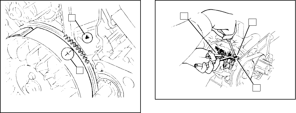
TP-5695 12/93 Scheduled Maintenance 3-21
1.“Y”Mark2.“T”Mark
2
1
1-827
Figure 3-22.Determining Top DeadCenter
12
3
1.FeelerGauge
2.Adjusting Screw3mm
SquareHead
3.Locknut; Use9mm
Wrench
1-831
Figure 3-23.Valve Adjustment
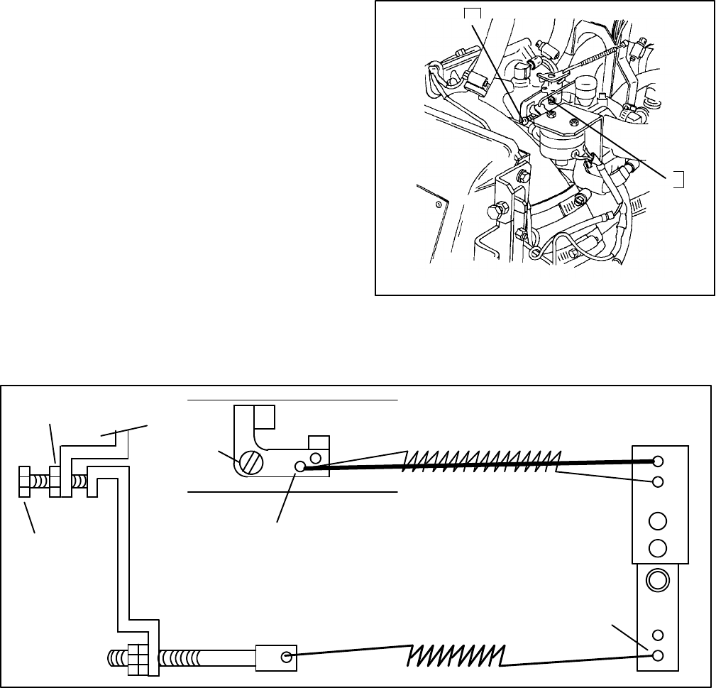
TP-5695 12/933-22 Scheduled Maintenance
Governor
The gear-driven centrifugaltype governorservesto
keep engine speed constantbyautomaticallyadjusting
the amountof fuelsupplied tothe engine according to
changesinload.
Lubrication
Lubricate governorlinkage at the specified interval
using whitelithiumgrease orlubriplate.
GovernorAdjustment
The gear-driven centrifugaltype governorservesto
keep engine speed constantbyautomaticallyadjusting
the amountof fuelsupplied tothe engine according to
changesinload.Noregularserviceisrequired on the
unit. The governorisadjusted during run-in at the
factoryand furtheradjustmentshould notbe needed
unless greatly varying load conditionsare encountered
orifpoorgovernorcontroldevelopsafterextended
usage.See Figure 3-25 forcorrectplacementof
governorlinkage (modelsmay vary).
60 Hzgeneratorsetsare designed to operate at60-63
Hz,3600 rpmunderfull load and 3780 rpmunderno
load.50 Hzgeneratorsetsare designed to operate at
50--52.5Hz,3000 rpmunderfull load and 3150 rpm
undernoload.Tocheckspeed,usehand tachometeror
frequency meter.Usethe following procedureto adjust
governor.
1.Loosen governorarmlocking nut. See
Figure 3-24.
2.Movethe governorarmend fullyinthe direction
shown(towardthe electric chokesolenoid)and
readjustgovernorscrew.Tighten locking nut.
3.Startengine and run toreach operating
temperature.
4.Applyfull load and turn engine speed adjustment
screwto 3600 rpmfor60 Hzgeneratorset, 3000
rpmfor50 Hz set.
5.Check regulation byapplying and removing full
load.
6.STOPgeneratorset.
1
2
1.MixtureScrew
2. IdleSpeed Screw3.GovernorAdjustment
1-829
3
Figure 3-24.GovernorAdjustment
Carburetor
Governor
Adjustment
Screw
ThrottleRod/Spring
GovernorSpring
GovernorCross Shaft
GovernorRod OuterHole
HoleNearest
toPivotPoint
PivotPoint
Locknut
Figure 3-25.GovernorLinkage
TP-5695 12/93 Scheduled Maintenance 3-23
WattageRequirements
Iftheratedcapacityofthegeneratorsetisexceeded,the
circuitbreakerlocatedonthecontrollerwilltriptoprotect
the generatoragainstdamage.Tripping could be
caused byashortinthe ACcircuitinthe craft orsimply
byhaving too manyapplianceson at the sametime
resulting in an overload condition. If the circuitbreaker
trips, the setmay continue running but therewill be no
ACoutput tothe protected circuit. Beforeresetting the
circuitbreaker,turnoffsomeoftheappliancesandlights
inside the craft to bring the load downwithinthe rated
limitsoftheset.Ifthisisdoneandthecircuitbreakertrips
again afterbeing reset, see a qualified electrician.
Formoreinformation regarding generatorsetcapacity,
see Installation—GeneratorSelection and Wattage
Requirements.
GeneratorService
General
Undernormalconditionsgeneratorservicewill notbe
requiredonaregularbasis.Ifoperatingunderdustyand
dirty conditions,useDRYcompressed airto blowdust
outofthegeneratoratfrequentintervals.Dothiswiththe
generatorsetoperating and direct the streamofairin
through the cooling slotsat the end of the generator.
The end bracketbearing should be replaced every
10,000 hoursofoperation.Have bearing replaced
soonerifbearing inspection indicatesexcessiverotor
end playorbearing damage fromcorrosion orheat
buildup.The end bracketbearing issealed and requires
no additional lubrication.All generatorservicemustbe
performed byan authorized service dealer/distributor.
TP-5695 12/933-24 Scheduled Maintenance
StorageProcedure
It isrecommended that the craft be afloatwhen the
generatorsetisprepared forstorage sincethe engine
mustbe started.
1.Add fuelstabilizertofueltank.Use
recommendationsof fuelstabilizermanufacturer.
2.Startgeneratorsetand run until operating
temperatureisreached orabout15 minutes.Stop
generatorset. Drain oil fromcrankcasewhile
engine is still warm.Replace oil filter.Refill
crankcasewithspecified weightoil.
NOTE
Forstorage,seawatermustbe replaced with
antifreezeasdescribed insteps3a--cordrainedas
described insteps4a--c.
3.Closeseacockandremovehoseatseacock.Place
hosein a containerofcoolant/antifreeze.
Containershould have approximately1--2U.S.
gallons(3.7--7.5 L)ofantifreeze.Amixture of50%
ethylene glycoland 50%clean,softened wateris
sufficient.
a.With a suitablecontaineratexhaustoutlet, run
generatorsetuntil coolantdischarge is
observed atexhaustoutletoruntil coolant
mixtureisusedup.Donotallowcoolantmixture
toflowintowaterways.Stop generatorset.
b.Connecthosetoseacock.Leaveseacock
closed.
c.Check coolantlevelofheatexchangerand add
ifnecessary.
NOTE
If steps3a--cwere performed toreplace
seawaterwith antifreeze,omitsteps4a--c.
4.Closeseacockanddrainallseawateroutofcooling
system.
a.Drainseawaterfromstrainerand seawater
pump.
b.Removezincanode orend cap on heat
exchanger,whicheverismoreconvenient, to
drainonlyseawater.Useanairhosetoblowout
anyremaining seawater,ifnecessary.Check
coolantlevelofheatexchangerand add if
necessary.
c.Drainseawaterfromexhaustwaterline.
NOTE
Iffreezingtemperatureswillbeencounteredduring
storage,be sure engine coolantis capable of
withstanding the lowestpossibletemperatures.
Generally,amixture of50%ethylene glycoland
50%clean,softened wateris sufficient.
5.Removesparkplugsand pourone teaspoon of
engine oil into eachcylinder.Crankthe engine
severaltimestocoat the cylinderwallswith oil.
Reinstall the sparkplugs.
6. If fuelstabilizerwasnotadded tofueltank,drain
fuelcompletelyfromfueltank.Gumdepositswill
develop ifgasoline is stored forthe season.
7.Clean exteriorofgeneratorsetand spread a light
filmofoil orsilicon sprayoveranyexposed
surfaceswhichmaybesubjecttorustorcorrosion.
8.Using tape,sealairinlet, exhaustpipe,and fuel
tank cap.
9.Disconnectand remove battery.Battery should be
placedinawarm,drylocation forperiodofstorage.
Recharge batteryonceamonthtomaintainfull
charge.
10.Coverentire unitwith a dustcover.

TP-5695 12/93 Troubleshooting 4-1
Section 4.Troubleshooting
When troublesoccur,do notoverlook simplecauses.A
starting problem, forexample,could be caused by
improperfueloranemptyfueltank.The followingcharts
listsomecommon problems. If proceduresinthis
manualdo notexplain howtocorrect the problem, take
the generatorset to an authorized service
dealer/distributor.Tellthe dealerexactlywhathappened
when the problemoccurred and ofanyadjustments
made tothe set.
Engine
ProblemPossibleCause Corrective Action
Unitwill notcrankWeakordead batteryRecharge or replace battery
U
n
i
t
w
i
l
l
n
o
t
c
r
a
n
k
Reversed orpoorbattery connections.
Poorground.Check connections
Fuse blownincontrollerReplacefuse
Defectivestart/stop switchCheck function,replace asnecessary.
DefectivestartersolenoidCheck startersolenoid and wiring.Replace
asnecessary.
DefectivestarterAttemptstarting bydirectconnection to
battery.Replace/repairasnecessary.
Unitcranks butwill
n
o
t
s
t
a
r
t
Outof fuelReplenish
U
n
i
t
c
r
a
n
k
s
b
u
t
w
i
l
l
notstartClogged fuelscreen Clean fuelscreen
n
o
t
s
t
a
r
t
Faultyantidieseling solenoidReplacesolenoid
Airintakeclogged Clean or replace
Faulty sparkplug(s)Replace(and regap)sparkplug(s)
Loosesparkplug connection Reconnectwires
Faultyground (--) connection Clean and retighten
Carburetoradjustmentwrong Adjustcarburetor
Defective electricfuelpumpCheck pressure.Replace asnecessary.
Shorted oropen ignition coil Replacecoil
Weakordead batteryRecharge or replace
Bad fuelmixtureReplacefuel;clean carburetor
Flooded carburetorWaitafewminutesand attemptrestart
Engine malfunction See authorized Kohlerservice
dealer/distributor
Engine starts,but
d
o
e
s
n
o
t
c
o
n
t
i
n
u
e
t
o
No generatoroutputvoltage Check ACvoltage
E
n
g
i
n
e
s
t
a
r
t
s
,
b
u
t
does notcontinueto
r
u
n
a
f
t
e
r
s
t
a
r
t
s
w
i
t
c
h
No/lowoil pressureCheck oil pressure and pump
d
o
e
s
n
o
t
c
o
n
t
i
n
u
e
t
o
run afterstartswitch
isreleasedDefectivelowoil pressure(LOP)safety
shutdownswitchCheck LOPshutdownswitch
High temperatureshutdownCheck cooling system
Defective high exhaust temp.(HET)and/or
high watertemp.(HWT)safety shutdown
switch(es)
Check HETand/orHWTshutdown
switch(es)
Hardstarting Stale orbad fuelReplacefuel
H
a
r
d
s
t
a
r
t
i
n
g
Fuelvaporlock Check fuel line routing
Faulty sparkplug(s)Replace(and regap)plug(s)
Weakignition coil Replace
Carburetoradjustmentwrong Adjustcarburetor
Airintakeclogged Clean

TP-5695 12/934-2Troubleshooting
Engine(Continued)
ProblemPossibleCause Corrective Action
Stops suddenlyOutof fuelReplenish
S
t
o
p
s
s
u
d
d
e
n
l
y
Airintakeclogged Clean
Fuse blownincontrollerReplacefuse
DefectiveseawaterpumpimpellerReplace
Clogged seawaterstrainerClean strainer
Ignition coil failureCheck forspark
Fuel line restriction Check fuel linesand tank
Fuelvaporlock Check fuel line routing
Defective electricfuelpumpCheck pump
Dirtyfuelscreen Clean fuelscreen
Faulty sparkplug(s)Replacesparkplug(s)
No/lowoil pressureCheck oil pressure and pump
Defectivelowoil pressure(LOP)safety
shutdownswitchCheck LOPshutdownswitch
High temperatureshutdownCheck engine coolantsystem
Defective high exhaust temp.(HET)and/or
high watertemp.(HWT)safety shutdown
switch(es)
Check HETand HWTshutdownswitch(es)
Loss ofACoutputSee authorized Kohlerservice
dealer/distributor
Faultyantidieseling solenoidReplacesolenoid
Lacks powerAirintakeclogged Clean
L
a
c
k
s
p
o
w
e
r
Bad orstalefuelReplacefuel
Faulty sparkplug(s)Replace(and regap)plug(s)
Impropertiming Check timing
Chokesolenoid defectiveCheck and/orchange
Engine notoperating atrated RPMCheck governor
GovernoradjustmentsincorrectAdjustgovernor
Carbon build-up Clean carbon fromcylinderheads
Impropercooling Inspectcooling system
Dirtyfuelscreen Clean screen
Defectiveignition coil Replacecoil
Fuel line restricted Check fuel lines
Engine overloaded Reduceload
Carburetoradjustmentwrong Adjustcarburetor
Operates erraticallyAirintakeclogged Clean
O
p
e
r
a
t
e
s
e
r
r
a
t
i
c
a
l
l
y
Stale orbad fuelReplacefuel
Fuelpumpvaporlock Allowunit tocooland attemptrestart
Clogged fuelscreen Clean screen
Faulty sparkplug(s)Replacesparkplug(s)
CarburetoradjustmentincorrectAdjustcarburetor

TP-5695 12/93 Troubleshooting 4-3
Engine(Continued)
ProblemPossibleCause Corrective Action
OverheatsImpropercooling Check intake and outletopenings.Check
coolantleveland pressurecap.Check raw
waterstrainer.
ThermostatdefectiveReplace
Sea strainerclogged Clean sea strainer
Carburetoradjustment too lean Adjustcarburetormixture
Engine ignition timing incorrectAdjust timing
Unitisnoisy ExhaustsystemleakCheck exhaustsystem
U
n
i
t
i
s
n
o
i
s
y
Exhaustsystemnotsecurelyinstalled Check forloose parts
Broken ordamaged vibromountsCheck vibromounts
Noinstallation clearance(unithits craft
structure orcompartment)Check clearances
Nocompartmentsound insulation Install approved insulation
Excessivevibration engine/generator
(internal imbalance)See authorized Kohlerservice
dealer/distributor
Loose orvibrating sheetmetalCheck shrouds
ElectricalSystem
ProblemPossibleCause Corrective Action
Batterywill not
c
h
a
r
g
e
Loose orcorroded connectionsClean and tighten connections
B
a
t
t
e
r
y
w
i
l
l
n
o
t
chargeSulfated orworn-outbatteryCheck electrolyteleveland specificgravity
(batterieswithfillercapsonly)
Defective battery charging systemCheck charging system
Battery charging fuse blownReplacefuse. If fuse blowsagainsee
authorized Kohlerservice dealer/distributor
Starterdoes not
w
o
r
k
p
r
o
p
e
r
l
y
Loose orcorroded connectionsClean and tighten looseconnections
S
t
a
r
t
e
r
d
o
e
s
n
o
t
workproperlyLowbatteryoutputCheck electrolyteleveland specificgravity
(batterieswithfillercapsonly).Check
battery voltage.
DefectivestartersolenoidReplacestartersolenoid
Defectivestart/stop switchReplaceswitch
Defectivewiring Check wiring
Startercranks
slowlyLowbatteryoutputCheck electrolyteleveland specificgravity
(batterieswithfillercapsonly)
s
l
o
w
l
y
Too heavy viscositylube oil Use properviscosityoil
Loose orcorroded wiring Clean and tighten looseconnections
High startercurrentdraw Rebuild or replacestarter
Battery cable undersizeSee Installation Section--Electrical
Systems

TP-5695 12/934-4Troubleshooting
Generator
ProblemPossibleCause Corrective Action
NoAC outputCircuitbreakerinOFF position ResetbreakertoONposition
N
o
A
C
o
u
t
p
u
t
Circuitbreakertripped due to overload on
generatorsetReduceload.See Wattage Requirements.
ResetbreakertoONposition.
Ship-to-shoretransferswitchin“OFF”or
“SHORE”position Turnswitchto generatorpower
NoDC powertocontrollerCheck battery connections
Controllerfuse blownReplacefuse
Generatormalfunction such as capacitor
orotherinternalfaultSee authorized Kohlerservice
dealer/distributor
Lowoutputor
e
x
c
e
s
s
i
v
e
d
r
o
p
i
n
Engine speed too lowAdjustgovernor
L
o
w
o
u
t
p
u
t
o
r
excessive drop in
v
o
l
t
a
g
e
Generatoroverloaded Reduceload.See Wattage Requirements.
v
o
l
t
a
g
e
Engine in poorcondition If routine servicesare performed and
condition persists,see authorized Kohler
dealer/distributor
DefectivecapacitorSee authorized Kohlerservice
dealer/distributor
High generator
outputvoltageDefectivecapacitorand/orpoorwiring
connectionsSee authorized Kohlerservice
dealer/distributor
o
u
t
p
u
t
v
o
l
t
a
g
e
Excessivespeed orfrequency Adjustgovernor.Check governorlinkage
and spring fordamage orbinding.
Will notcrankNoDC powertocontrollerCheck battery connections
W
i
l
l
n
o
t
c
r
a
n
k
Controllercircuit fuse blownReplacefuse and attemptstart-up. If fuse
blowsagain,contactauthorized Kohler
service dealer/distributor.
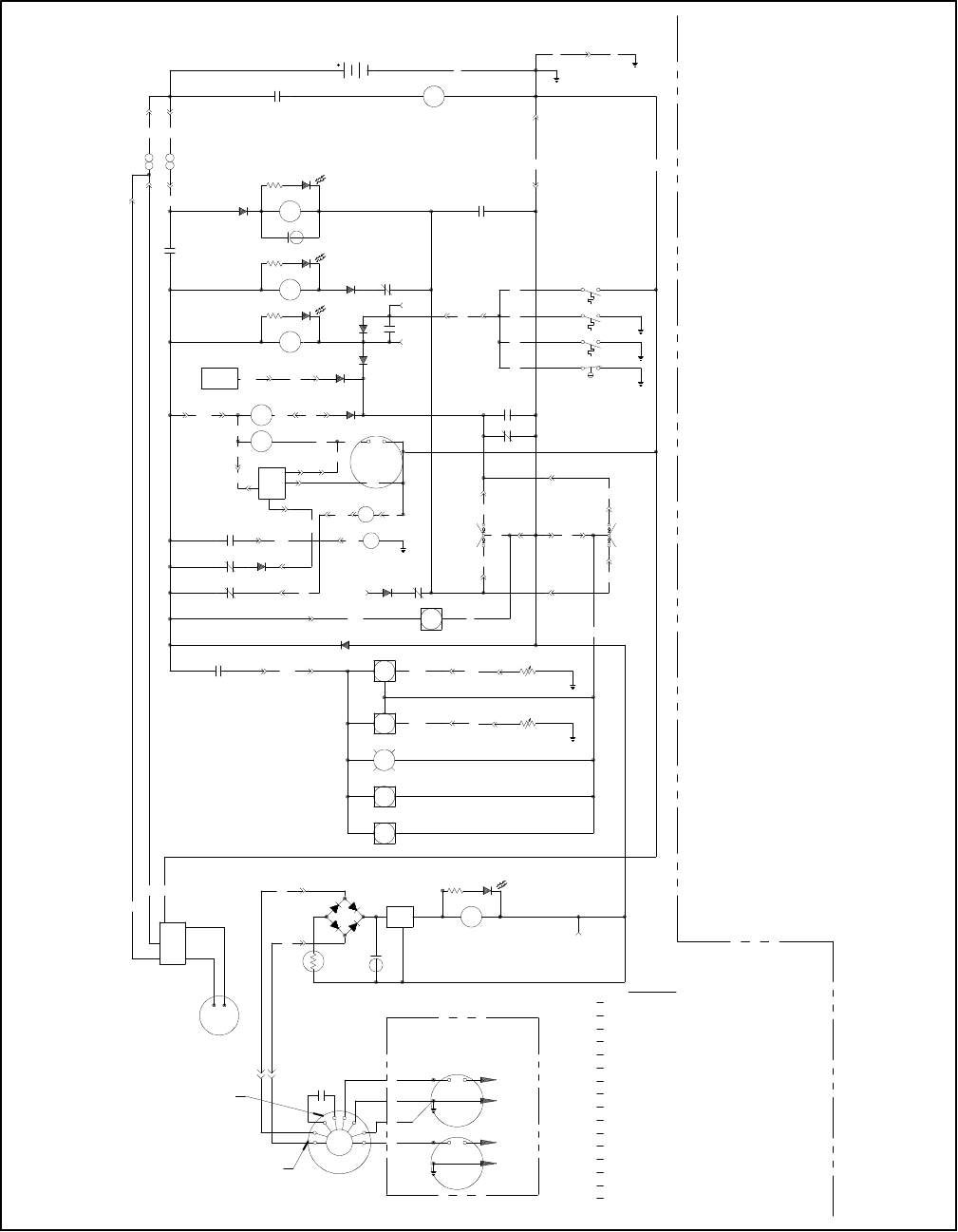
TP-5695 12/93 Wiring Diagrams5-1
Section 5.Wiring Diagrams
THERMALSWITCH
BATTERY VOLTMETER
WATERTEMPERATUREGAUGE
OILPRESSUREGAUGE
WATERTEMP.SENDER
HOURMETER
ANTI--DIESELSOLENOID
CHOKE
FUELPUMP
STARTERMOTOR
FAULTSHUTDOWN RELAY
ENGINECRANKRELAY
ENGINERUN RELAY
AC CRANKDISCONNECTRELAY
L1
LO
120/240 V.CONNECTION
L2
GROUND
HAZARD
1
2
3
4
WTSOILPRESSURE SENDER
TS
BV
WT
OP
OPS
HR
AD
CH
FP
S
K4
K3
K2
K1
BOARD
CHOKE
HOT
P5--2
P5--4P4--3
8N
N
P1--8
5
7C
BV
BC N
N
BC
K2
HR
7N
VIOLET
P
N
SCHEMATIC
BLACK
1
2
3
4
55
66
B1
B2
OWNERSMANUAL
RATINGSEE
FORAMPERAGE
LEGEND
AUXILIARYWINDING
BATTERYCHARGING
WINDING
AUXILIARYCAPACITOR
EXCITATION
ALTERNATOR
FAULTSHUTDOWNTIMEDELAY RELAY
C1
2
1
B1P1--3
P1--6
B2
+12V
VR1
K5
K1
LED1R1
BR1
3
+--
5
4
1A
REGULATOR
VOLTAGE
ALTERNATOR
CHARGING
BATTERY
ON
GEN
WTS
P3--2
TAN
OPS
P3--3
BLUE
LT
WT
OP
P3--4
76
P2--3
K1
D4
73
P2--1HR
5A
D8
FN
P1--12
5A
D5
75
K1START
REMOTE
STOP
P3--6
43
P3--5
47
43
P2--8
P2--7
START
P1--15
37
37
37
37
LOWOILPRESSURE
HIGHEXHAUST TEMP.
HIGHENGINETEMP.
STOP
P2--4
P2--5
P1--9
47
N
N
K1
70
P3--1
K4
P1--471 P2--9
K3S
FP
CH TS
K4
1A
D7
P1--10
72
SYSTEM
IGNITION
P1--7
AD4573
P2--6
N
5A
1A
D3
D6
30
P1--13
1A
D1
13
P2--2
K1
K4
LED4R4
K1
D9
K2
K3
LED3R3
M
12 VOLT
+C2
LED2
R2
K2
1A
D2
S
P1--14
P1--1
1A
K1
PTC1N
P1--2
P4--16
BC
37 HIGHEXHAUST TEMP.
10A
10A
CONTROLLER
P
ENGINE
N
NN
P4--20
P4--21
P4--18
45
72
P4--8
P4--15
P4--1P4--11
P4--22
P4--9
7N
P4--1473 P5--3
P5--1
73
73
71
P4--4
N70
P4--13
P4--2
P1--5
P8--1P8--2
P4--19
P6--1P6--2
246482-D
Figure 5-1.SchematicWiring Diagram--3.5CFZ,4CZ,5CFZ,and 6.5CZ
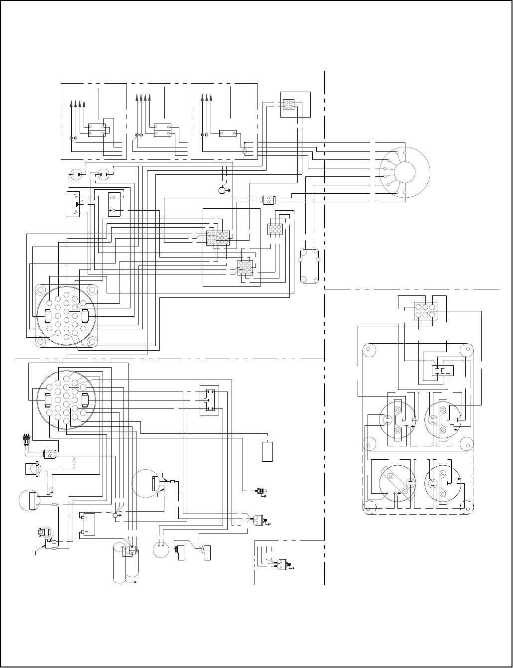
5-2Wiring DiagramsTP-5695 12/93
FOR AMPERAGE
RATING SEE
OWNERS MANUAL
CIRCUIT BREAKERS
220 V. CONNECTION
L0
GRD
4 3 2 1
LO (NEUTRAL)
GRD L1
BC
72378N
45
73
71
5
2
4
9
15
20
22
21
19
BC
14
8
31
L1
GRD
LO
1234
L2
GRD
L0
120/240 V. CONNECTION
GRD
LO
1234
L2
GRD
CIRCUIT BREAKERS
75
8N
P6
N73
34
2 1
CIRCUIT BOARD
HOT CHOKE
75
8N
N
J3
HOUR
BLK
VIOLET
VIOLET
BLK
TEMP
OIL
LT BLUE
VIOLET
VIOLET
BLK
BLK
BLK
BLK
PIN INSERTION END.
CONNECTOR SHOWN FROM
NOTE :
VOLT
TAN
BLACK
VIOLET
GREY/BLK
6
5
3
2
41
YEL/RED
(2 AND 4GAUGE REMOTE PANEL)
BACK VIEW OF PANEL
STOP
START
REGULATOR
VOLTAGE
1
2
ALTERNATOR
CHARGING
BATTERY
NBC
3
12
54
BC
N
N
7N
76
BC
7C
S
S
++
+
+
VIOLETVIOLET
VIOLETVIOLET
BLK
BLK
SWITCH
TEMPERATURE
HIGH ENGINE
N
N
SOLENOID
ANTI--DIESEL
SWITCH
THERMAL
CHOKE
70
73
72
SYSTEM
IGNITION
73
45
37
SWITCHES
TEMPERATURE
EXHAUST
N
NUT
GROUND
SENDING UNIT
TEMPERATURE
WATER
(OPTIONAL)
SWITCH
LOW OIL PRESSURE
SENDING UNIT/
OIL PRESSURE
(OPTIONAL)
FUEL PUMP
5
L0
5
120 V. CONNECTION
123
L1
B2 B1
7C
45566
55
66
B2
N
37 P1
N
P2
43
47
73
47 RELAY BOARD
43
1
2
3
4
55
66
B1
B2
N
SOLENOID
STARTER
76
73
43
N
47
P
P
P
N
10A
INPUT
STOPSTART
HOUR METER
N
BC
LUG
GROUND
J4
CAPACITOR
EXCITATION
ALTERNATOR
15 14 13
12 11 10
9 8 7
6 5 4
3 2 1
9
10A
CHRG.
BATT.
8
7
6
5
4
3
2
1
3
B1
2
6
47
514
N
43
37
P
71
N
ENGINE CONTROLLER
REMOTE PANEL GENERATOR
CIRCUIT BREAKERS
GREEN
GREEN/WHITE
OWNERS MANUAL
RATING SEE
FOR AMPERAGE
OWNERS MANUAL
RATING SEE
FOR AMPERAGE
45
71
70
BC
BC BC
BC
WHEN NOT USED.
TAPE LEADS ”5”OR ”7C”
7C
37 37
37
37
37
37
37
37
SWITCH
PRESSURE
OIL
G
GREEN YELLOW
B2 B1
N
N
N
7070
P4
P8
P3
73
P5
72
WK
N
BC
8N3772
73
45
73
53
8
14
19
21
22
20
15
BC
9
4
21
NN
P 7C
71
MOTOR
STARTER
BATTERY
NN
P7C
73
246482-D
Figure 5-2.Point-to-PointWiring Diagram--3.5CFZ,4CZ,5CFZ,and 6.5CZ
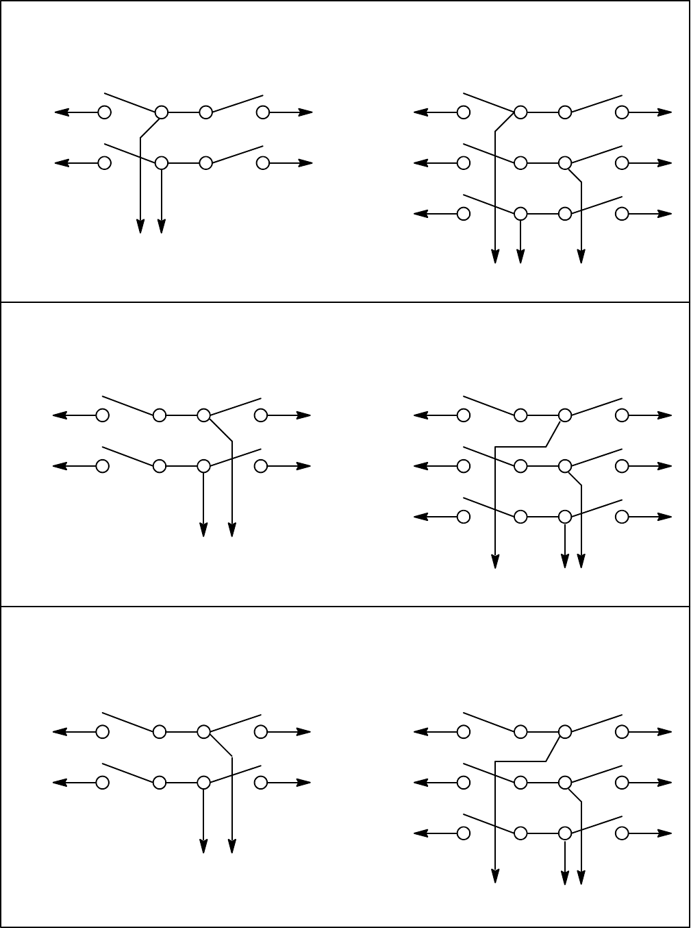
TP-5695 12/93 Wiring Diagrams5-3
Electro Switch
L1
L2
ToGenerator
SetToShore
Power
To Load
2-WireGeneratorSets
L1
L2
ToGenerator
SetToShore
Power
To Load
2-WireGeneratorSets
2-WireGeneratorSets
KrausNaimler/AmericanSolenoid
(Early RectangularDesign)
KrausNaimler/AmericanSolenoid
(NewerRound Design)
2 1 3 4
6 5 7 8
1 2 6 5
3 4 8 7
L1
L2
ToGenerator
SetToShore
Power
To Load
3 2 4 1
7 6 8 5
L1
L2
ToGenerator
SetToShore
Power
To Load
3-WireGeneratorSets
2 1 3 4
6 5 7 8
L0 10 9 11 12
1 2 6 5
3 4 8 7
9 10 14 13
L1
L2
ToGenerator
SetToShore
Power
To Load
3-WireGeneratorSets
L0
3 2 4 1
7 6 8 5
11 10 12 9
L1
L2
ToGenerator
SetToShore
Power
To Load
3-WireGeneratorSets
L0
Figure 5-3.MarineManual(Ship-to-Shore)TransferSwitch
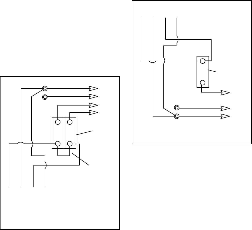
5-4Wiring DiagramsTP-5695 12/93
Four-LeadReconnectable(Single-Phase)GeneratorSetsWhereGenerator
OutputCanBeReconnected For120 voltor120/240 volt,60 Hz,
110 voltor110/220 volt,50 Hz
NOTE
When a generatorsetisreconnected to a voltage
different than nameplatevoltage,noticeshould be
placed on the unitindicating this change.Decalsforthis
purpose are availablefromauthorized Kohler
dealers/distributors.
120-or 110-Volt3-Wire 2-Pole
Configuration--Figure 5-4
Jumperlead to be placed on line side ofcircuitbreaker.
LeadsL1 and L2 can eitherbe left as separateleadsor
can be connected togetherdepending upon whichis
practicalforthe given application.Regardless of the
numberofphase(black)leadsused inthe application,
bothcircuitbreakersmusthaveleadsattached tothe
load side.Itisrecommended thatjumperlead be
maintainedforallstraight120-or110-voltsystemssince
ithelpsbalancethe load of the generatorset.
4321
StatorLeads
LO
GRD.
L2
L1
LO(Neutral)
Ground
LoadSide
LineSide
Circuit
Breaker
Jumper
Lead
60 Hz50 Hz
L0--L1120 volt110 volt
L0--L2120 volt110 volt
Figure 5-4.WithJumperLead
120-or 110-Volt2-WireConfiguration
Figure 5-5(Single Pole)
If the installation requiresa 120 or110 volt, 2-wire
system,asingle-polecircuitbreakermustbe used.See
Figure 5-5.When connecting statorphaseleads
together,theoutputlead(L1)mustbesizedaccordingly.
4321
StatorLeads
LO
GRD.
LO(Neutral)
Ground
Load
Side
Line
Side
1-Pole
Circuit
Breaker
L1
60 Hz50 Hz
L0--L1100-120 volt100-120 volt
Figure 5-5.120 Volt,2-Wire
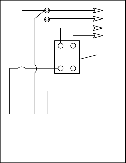
TP-5695 12/93 Wiring Diagrams5-5
120/240-or 110/220-Volt
Configuration--Figure 5-6
Jumperlead notused. If unitwasoriginallywired for
straight120 or110 volt, be surejumperlead isremoved
(see Figure 5-6forlocation).LeadsL1 and L2 are
differentphasesandmustneverbeconnectedtogether.
4321
StatorLeads
LO
GRD.
L2
L1
LO(Neutral)
LoadSide
LineSide
Circuit
Breaker
Ground
60 Hz50 Hz
L0--L1120 volt110 volt
L0--L2120 volt110 volt
L1--L3240 volt220 volt
Figure 5-6.WithoutJumperLead
6
TP-5695 12/93 Installation 6-1
Section 6. Installation
Introduction
Usethis section asa guide when installing the Marine
generatorset, then refertoSection 2.Operation for
specific serviceinstructions.Reliable and safe
generatorsetoperation dependslargelyupon proper
installation.Rememberthat the generatorsetwill
probablybe the craft’s solesource ofelectricalpower.
When installingamarine generatorset, itis
recommended that the installation complywith all
applicableRegulationsand Standards.See Reference
Materialfordocumentsissued bygoverning agencies.
Information presented hereshouldbefollowed in
planning and making installations.Specificationsgiven
should be used onlyininitialplanning.Usecurrent
dimension drawingsand wiring diagrams.
NOTE
Awood block islocated undersome generatorsetend
bracketsto preventdamage during shipment. Forthe
samereason,metalbracketsare used to attachsome
generatorsetstotheirwood shipping bases.These
itemsMUSTbe removed priortoinstallation in orderto
provide adequatevibration clearance during generator
setoperation.Checkthatallpacking material,literature,
and loose accessoriesareremoved fromgeneratorset
priorto operation.
GeneratorSelection and
WattageRequirements
Totalwattage requirements(lights,motors,appliances)
mustbe considered when selecting a generatorset, or
when sizing wattage usage where availablespace and
construction limit the size of the generatorset. The
4-lead reconnectable generatorsetcan be connected
for120 voltor120/240 volt60 Hz(110 voltor110/220
volt50 Hz),see Section 5.Wiring Diagrams.
NOTE
When a generatorsetisreconnected to produce a
voltage different than nameplatevoltage,noticeshould
beplacedontheunitindicatingthischange.Decals(part
number246242)forthispurpose are availablefrom
authorized Kohlerdealers/distributors.
Lighting Load
The lighting load isusuallyeasiest tocalculate. Inmost
cases,simplyadd the wattage ofeachlampto be
operated off the generatorset. Notethatinmany
applications,notall of the lightsorlampsareinthe
generatorsetACcircuit—some areDC powered bythe
12-voltbatteryinthe craft. Makesurethe total includes
onlylightsactuallyon the generatorsetACcircuit.
MotorLoads
When figuring generatorsetcapacityrequirementsthat
include electricmotors,do notoverlookthe high current
demanded bythe motorsduring start-up.The in-rush or
starting currentistypically2--3timeshigherthan that
required when the motor reachesnormaloperating
speed.Reservecapacitymustbe allowed forin-rush
demandsplusotherloadswhichcould be on the line as
the electricmotorstarts.
Airconditioning unitsare perhapsthe mostcommon
type ofmotorload forgeneratorsetsinmarine
applications.The starting characteristics of the different
varietiesofairconditioners varygreatly—one particular
12,000 Btu unithas, forexample,lowerstarting
requirementsthan a 10,000 Btu unitofanothermake.
When onlyone unitisinvolved, thereisusuallyno
starting problem,provided the lighting and appliance
load isnot too high when the unitis started.
Simultaneous starting of two airconditioning units,
however,can presentproblemsif the capacityis
marginal.Because of the variation instarting
characteristics of the variousmakesofairconditioners,
no definitestatementsaremade inthispublication
regarding multiple-motorstarting capabilitiesof the
marine generatorsetcovered.Delayed starting oruse
ofeasy-starting deviceson airconditionerunits should
be considered wheneversimultaneous starting ofmore
than one motorisinvolved.
The starting and running requirementsofsomemotor
loads common tomarine applicationsarelisted in
Figure 6-1;usethisasaguidewhenselectinggenerator
setcapacityrequirementsinvolving motorloads.See
Figure 6-2forgeneratorsetcapabilitiesregarding air
conditioners.

TP-5695 12/936-2Installation
Capabilitieswill varyaccording toKilowatt Derating
following.
Motor
Requirements
(HP)
Starting
(In-Rush)
WattsRunning
Watts
1/4 750 330
1/3 1000 400
1/2 1500 600
3/4 2000 750
1 3300 1100
2 4000 2000
3 5000 3000
Figure 6-1.MotorRequirements
ModelWattage
Will OperateAir
Conditionerof
SizeIndicated
“Powerto
Spare”for
Lighting
Appliances,
Tools
4CZ4000 One 13,500 Btu 2100
6.5CZ6500 One 13,500 Btu 4600
Two 13,500 Btu 2700
Figure 6-2.AirConditionerRequirements
(50 Hzunitswill have slightlylower“power
tospare”figures thanthose indicated)
Appliance Loads
Marine generatorsetsare often used tofurnishACfor
appliances such asTV,stereo,electricwaterheaters,
etc.Withthe exception of the resistance-type loads
such asthe waterheater,requirementsforappliances
are usuallylow.Suchloadsmustnot, however,be
overlooked when figuring totalrequirements.Reserve
capacity should be availableforanticipated appliance
loadsto avoid overloading ofaset. The average power
requirementsofsomecommon electricalappliances
are given inFigure 6-3.
Kilowatt Derating
Unitsarerated aslisted belowat1.0 powerfactor.
Deratethelisted ratingbyapproximately3.5%per1000
ft.(300m)whentheunitisoperatedataltitudesof500ft.
(150 m)ormore abovesea level.
3.5CFZ,50 Hz:3.5kWat77_F(25_C)and 3.5kWat
122_F(50_C).
4CZ,60 Hz:4kWat77_F(25_C)and 3.5kWat122_F
(50_C).
5CFZ,50 Hz:5kWat77_F(25_C)and 4.85 kWat
122_F(50_C).
6.5CZ,60Hz:6.5kWat77_F(25_C)and6kWat122_F
(50_C).
Electrical
Appliance
Motor
Starting
WattsRunning
Watts
AutomaticPilot-- 150--250
Blanket, Electric-- 50--250
Blender800 600
Broiler -- 1350
Depthometer -- 25--1000
Drill,3/8”600 350
Dryer,Hair -- 850--1200
Fan,Air
Circulating 50--200 25--100
Food,Mixer400 235
Heater,Space-- 750--1500
Heater,Water -- 1500
Iron -- 900--1200
LightBulbs-- (asindicated)
Pan,Frying -- 1200
Percolator,
Coffee -- 650
Radar -- 750--1500
Radio-- 50--100
Radiophone -- 100--200
Range,Electric
(perelement)-- 1000--1500
Soldering Gun -- 250
Television -- 300--750
Toaster -- 750--1200
WaterSystem500--1500 300--1250
Figure 6-3.Appliance AverageWattageRatings
(60 Hz)
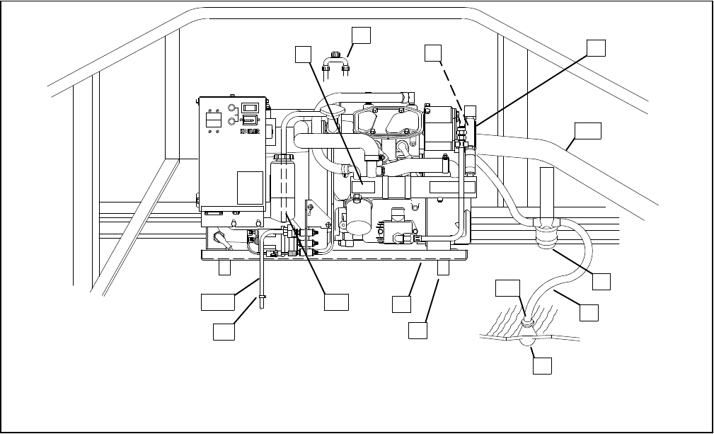
TP-5695 12/93 Installation 6-3
TOTALHOURS
00 000 1/10
10A
FUSE
BATT.
CHRG.
INPUT
NOTE
Usetwo hoseclampson each end of
all flexible exhausthoseconnections.
*Indicated componentsmustconformtoU.S.C.G.Regulations.
4
*5
6
7
8
*9
10
11
STOP/START
258000-D
2
1
13
*14 12
3
1.HeatExchanger
2.Siphon Break(See Instruction SheetTT-927 for
ProperInstallation.)
3.ExhaustMixer
4.Engine-Driven SeawaterPump
5.ExhaustHose
6.SeawaterStrainer
7.RawWaterline
8. IntakeThrough-Hull Strainer
9.Seacock
10.Mounting Base
11.Mounting Tray
12.CoolantRecoveryTank
13.HoseClamp
14.FuelLine
Figure 6-4.TypicalLocation and Mounting
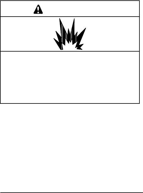
TP-5695 12/936-4Installation
Location
General
Considerthe following inselecting orconstructing a
generatorsetlocation.
Compartment/location mustallowadequatespacefor
ventilation,cooling and exhaustsysteminstallation,
service access tothe engine and generator,and proper
fuelsysteminstallation.
Engine stringersorotheravailablestructuralmembers
mustprovide adequatesupport forthe generatorset
weight.
Ageneratorsetcompartmentmustbesealed to prevent
exhaustgasesand fuelvaporsfromentering cabins.
Generatorsetslocated above deck musthave a
protectivecoverto preventdamage fromrain and water
splash.This covermustnotaffectcooling airflowand
serviceability.
SeeFigure 6-4foratypicalinstallationandSection1.for
dimensionsand weights.
Space
Locationshouldalloweasyaccesstothegeneratorset’s
engine,controller,cooling,andfuelsystemcomponents
forroutineservice.Enginecompartmentsareoftenideal
generatorsetlocations,butaccess should notbe
obstructed bypropulsion enginesorgeneratorand
controller.Also allowclearanceforvibration during
operation.Minimumrecommended clearancefor
vibration and cooling of top, front, rear,and sidesof
generatorsetis1 1/2in.(38 mm).
Mounting
Enginestringersgenerallyprovidethebestsupport fora
generatorset. Any structuralmembers considered for
mounting mustsupport the generatorsetweightand
withstand engine vibration.The generatorsetincludes
vibration mountsand mounting trays;additional
vibration isolating padsmaybe installed between trays
and bases.
Ageneratorsetshould be mounted ashigh aspossible
to avoid bilge splash and lower-lying vaporsand alsoto
allowdownward pitch of the exhaustline.Forangular
installation, the maximumoperation angle of the
engine/generatorsetis20_ (in all directions).
Ventilation
Ventilation isrequired tosupportengine combustion,
generatorcooling,and expulsion of flammable and
lethalfumes.Ventilation provisionsmustcomplywith
U.S.C.G.Regulationsgoverning sizing ofventsand
operator requirements.
Asarule,inletand outletventareas should each be
sizedtoaminimumof2sq.in.perft.(13sq.cm/30.5cm)
ofcraft’sbeam.Shouldthisrulein anyinstanceconflict
withU.S.C.G.Regulations,appropriateRegulations
shouldbefollowed.Ifany screening isused ininlets,
size ofhull/deck openings should be doubled.Vent
ducts should extend to bilgesto expelheavier-than-air
fumes.Ifthegeneratorsetistobemountedintheengine
compartment, airflowmustbe increased to allowfor
generatorset’srequirements.UL-listed ignition-
protected blowers should be installed in outletvents,
and wired to operate before engine(s)arestarted.
Snifferdevicesmayalsobe optionallyinstalled tocause
alarm,warning,orengine shutdownshould dangerous
fumesaccumulateinthe compartment.
WARNING
Explosion.
Gasoline vapors cancause explosion and
severeinjuryordeath.
Beforestarting generatorset, operate blower4
minutesand check engine compartment for
gasoline vapors.
Air requirementsforvariousmodelsare given in
Figure 6-5.The airintakesilencerprovides combustion
airtothe engine.Itisimperativethat the recommended
minimumclearance of1 1/2in.(38 mm)between duct
opening and anyenclosurewall notbe compromised.
Engine/generatorperformancewill be affected
adverselyif these guidelinesare not followed.
AirRequirements
CFM(L/min.)
ModelCombustion Cooling
3.5CFZ 18 (510)323 (9145)
4CZ18 (510)323 (9145)
5CFZ 18 (510)600 (16988)
6.5CZ18 (510)600 (16988)
Figure 6-5.AirRequirements
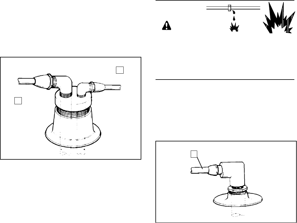
TP-5695 12/93 Installation 6-5
FuelSystems
FuelSupply
Generatorsets,inmostcases,mustdrawfuelfromthe
sametankasthe propulsion engines. If the tank’sfuel
pickup opening allows,amultiple diptube arrangement
(Figure 6-6)maybe used.An alternatetank,ifused,
shouldhaveasmallerseparatepickup openingallowing
asingle diptube (Figure 6-7).
1
2
1-788
1.FuelLine toPropulsion
Engine 2.FuelLine toGenerator
Set
Figure 6-6.DualDip Tubes
Forinstallationswherethe highestpointof the gasoline
source(fueltank)isabovethegeneratorsetcarburetor,
an auxiliaryfuelshutoff valveisrequired.Thisfuel
shutoffvalveshouldbeclosedwhenthegeneratorisnot
in useto prevent fuel leakage resulting fromfuelflow
throughthe fuelpumpandintothecarburetorshouldthe
floatvalve notseatproperly.
NOTE
FuelsystemsmustconformtoU.S.C.GRegulationsand
tests.
WARNING
Explosive fuelvapors.
Cancause severeinjuryordeath.
Useextremecarewhen handling,storing,
and using fuels.
Explosive fuelvapors cancause severeinjuryor
death.Fuel leakage can cause an explosion.Do not
modifythe tankorpropulsion engine fuelsystem.Craft
mustbe equipped withatankallowing one of the two
pickup arrangementsdescribed.Tankand installation
mustconformtoU.S.C.G.Regulations.
1
1-788
1.FuelLine toGeneratorSet
Figure 6-7.SingleDip Tube
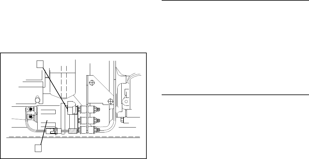
TP-5695 12/936-6Installation
Anti-Siphon Provisions
Anti-siphon devicesmustbe installed ifany section of
fuel line liesbelowthe highestpointof the fueltank.The
anti-siphon deviceshould be eitheraspring-loaded
check valve(tested tofunction withthe particular
installation’s siphon head),oran electricallyoperated
shutoff valve(ULignition-protected, tested toU.S.C.G.
Regulations)whichmaybe operated manually.Acheck
valveshouldbeinstalled ata pointabovefueltank’s
highestpoint, secured tocraft’s structure,and be
accessiblewithoutremoving anypermanentstructure.
The fuel line section between the tankand check valve
mustbe located abovethe tank’shighestpoint. An
electric shutoff valveshouldbeinstalled at the tank’s
fuelwithdrawalfitting,and be wired to open when the
generatorsetengine is cranking or running.
Anti-siphon holesdrilled infueldiptubeswithinthe tank
are notreliable anti-siphon devicesastheybecome
ineffectivewhen restricted bydirtorgum.
FuelLines
Metalliclines should be used fromthe tankto a flexible
hosesection connecting metallicline tothe engine fuel
pump.Metalliclinesmusthavewall thicknessofatleast
0.029 in.(0.74 mm).Seamless annealed nickelcopper,
copper-nickel,orcoppertubing mustbe used.The
flexiblesection(necessaryto allowvibrationalmotionof
the generatorsetduring operation)mustbe U.S.C.G.
TYPE A HOSE,marked and tagged according to
Regulations.Metallicline mustbe supported within 4 in.
(102 mm)ofits connection tothe flexiblesection.See
Figure 6-8forfuelpumpinletconnection.
1.1/4in.NPT Female
Pipe Thread 2.ElectricFuelPump
1
2258000-D
Figure 6-8.FuelPumpInletConnection
Anyin-line fuelfiltersorstrainersmustconformto
U.S.C.G.Regulations,mustbe independentlymounted
tothe craft’s structure,and mustbe accessiblefor
servicing withoutremoving anypermanentstructures.
NOTE
If afuelstrainerisinstalled,eachfuelfilterand strainer
mustbe supported on the engine orboatstructure
independent fromitsfuel line connections,unless the
fuelfilterorstrainerisinsideafueltank.
FuelPump Lift Capabilities and
FuelConsumption
Figure 6-9listselectricfuelpumplift capabilitiesand
fuel line sizes.Figure 6-10 showsgeneratorset fuel
consumption rates.
ModelFuelPump
Max.Lift ft.(m)Fuel InletSize
I.D. in.(mm)
3.5CFZ 3(0.9)3/8(9.5)
4CZ3(0.9)3/8(9.5)
5CFZ 3(0.9)3/8(9.5)
6.5CZ3(0.9)3/8(9.5)
Figure 6-9.FuelPump Lift and FuelLineSize
Loadand GPH(L/hr.)
Model1/4 1/2 3/4Full
3.5CFZ 0.42
(1.59)0.50
(1.89)0.59
(2.23)0.68
(2.57)
4CZ0.48
(1.81)0.55
(2.08)0.62
(2.34)0.68
(2.57)
5CFZ 0.44
(1.67)0.54
(2.04)0.66
(2.50)0.80
(3.03)
6.5CZ0.53
(2.00)0.62
(2.34)0.86
(3.25)1.02
(3.86)
Figure 6-10.FuelConsumption
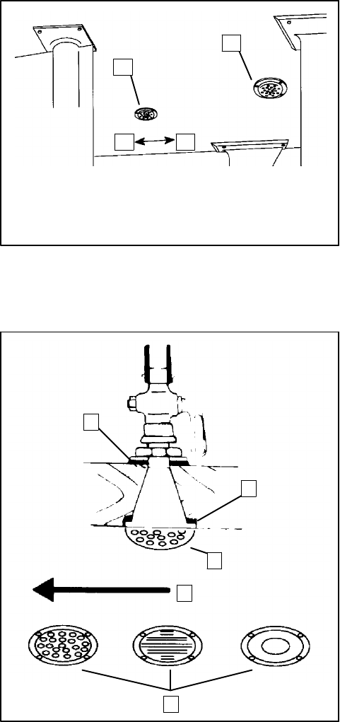
TP-5695 12/93 Installation 6-7
Cooling Systems
General
The following featuresare necessaryinthe cooling
system.
Anintake thru-hull strainer(seacock cover) mustbe
screened to prevententryof foreign objectsand must
notbe aligned (inrelation to direction of travel)withthe
propulsion engine intake.See Figure 6-11.The
recommended thru-hull strainershould be flush
mounted.Strainerswithslotted holesmustbe installed
withtheirslotsparalleltothe direction ofvessel
movement. The area of the straineropening(s)mustbe
equalto orgreaterthan the inside diameterof the
waterline hosetothe seawaterpump.
Anintakethru-hull strainermustnotbe of the scoop or
cup design.This stylecan causearamming effectand
forcewaterupward,past the seawaterpump,and into
the engine cylinderswhen the vessel ismoving and the
generatorsetis shutdown.Hull designsincorporating
sea chestsare also notsuitableforintakethru-hull
strainers.Asea chestisaconcavemolded-in-the-hull
chamberthatisalso aligned tothe direction of travel.A
sea chestconfiguration appliesa positive pressure
similartoascoop-type thru-hull strainer.
Aseacock isto be mountedto hull,assembled ontothe
intake and accessibleforoperation.Figure 6-12 shows
atypical installation. Install the canvason the outside of
the hull,and the canvasor rubberpacking on the inside
of the hull.
If caulking isused tosealthe seacock,be sure not to
applyan excessive amount. Excess caulk can cause
improperwaterflowand insomecasesdevelop a
barrierwhichcanforcewaterupward,pasttheseawater
pump,and intothe engine cylinderswhen the vessel is
moving and generatorsetis shutdown.
NOTE
Intakesare positioned inrelation tovesseltravel
so neitherwill be inthe wake of the other.
1
2
4 3
1-789
1.GeneratorSet Intake
2.Propulsion Engine
Intake
3.Aft
4.Fore
Figure 6-11. Intake Strainer
1
2
3
4
1. Inside Packing
2.Outside Packing
3.Seacock Cover
4.Direction ofVessel
Movement
5.TypicalIntakeThru-Hull
Strainers
51-789
Figure 6-12.Seacock Installation
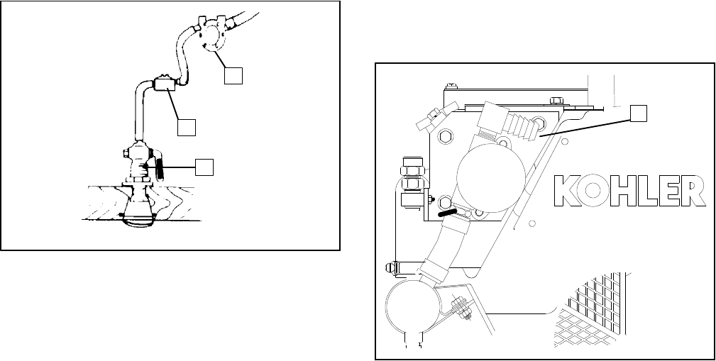
TP-5695 12/936-8Installation
Aseawaterstrainerofsufficientcapacity should be
mounted tothe seacock orpermanentstructure ata
pointnothigherthan the seawaterpump.The strainer
shouldbeaccessibleforservicing.SeeFigure 6-13fora
typical installation.The optionalKohlerseawater
straineristhreaded for1/2NPTfittings.
1
2
3
1-789
1.SeawaterPump
2.SeawaterStrainer3.Seacock
Figure 6-13.SeawaterStrainer
NOTE
Someseawaterstrainersinclude seacock and intake
thru-hull strainer.
Waterlines fromthe seacock tothe engine-driven
seawaterpumpcan be coppertubing orflexible hose.A
flexiblesection ofhoseisused forthe actualconnection
tothe seawaterpumpto allowvibrationalmotion of the
generatorsetduring operation.The hoseshould have
aninsidediameterof3/4in.(19mm).Copperlineshould
be supported within4in.(102 mm)ofits connection to
the flexiblesection.
NOTE
A5/8in.(16 mm)waterline hosecan be substituted for
the recommended 3/4in.waterline hose.
Piping shouldbekeptstraightand as shortaspossible.
See Figure 6-14 forthe seawaterconnection tothe
seawaterpumpinlet. The seawateroutletis combined
with engine exhaustgases.(Onsound shielded units,a
small section ofmolded hoseisrequired forthe
seawaterinletconnection.)
1
ADV-5792-D
1.3/4in.SeawaterPumpInlet
Figure 6-14.SeawaterInletConnection
Closed/HeatExchanger
Aclosed,heatexchangercooling system, the best
alternativeformostapplicationsespeciallyifcraft isto
be operated insaltwatersorwaterswith high silt
content, isprovided aspartof the generatorset.
Service accessibilitymustbe provided forthe heat
exchangerpressurecap.See Figure 6-15.
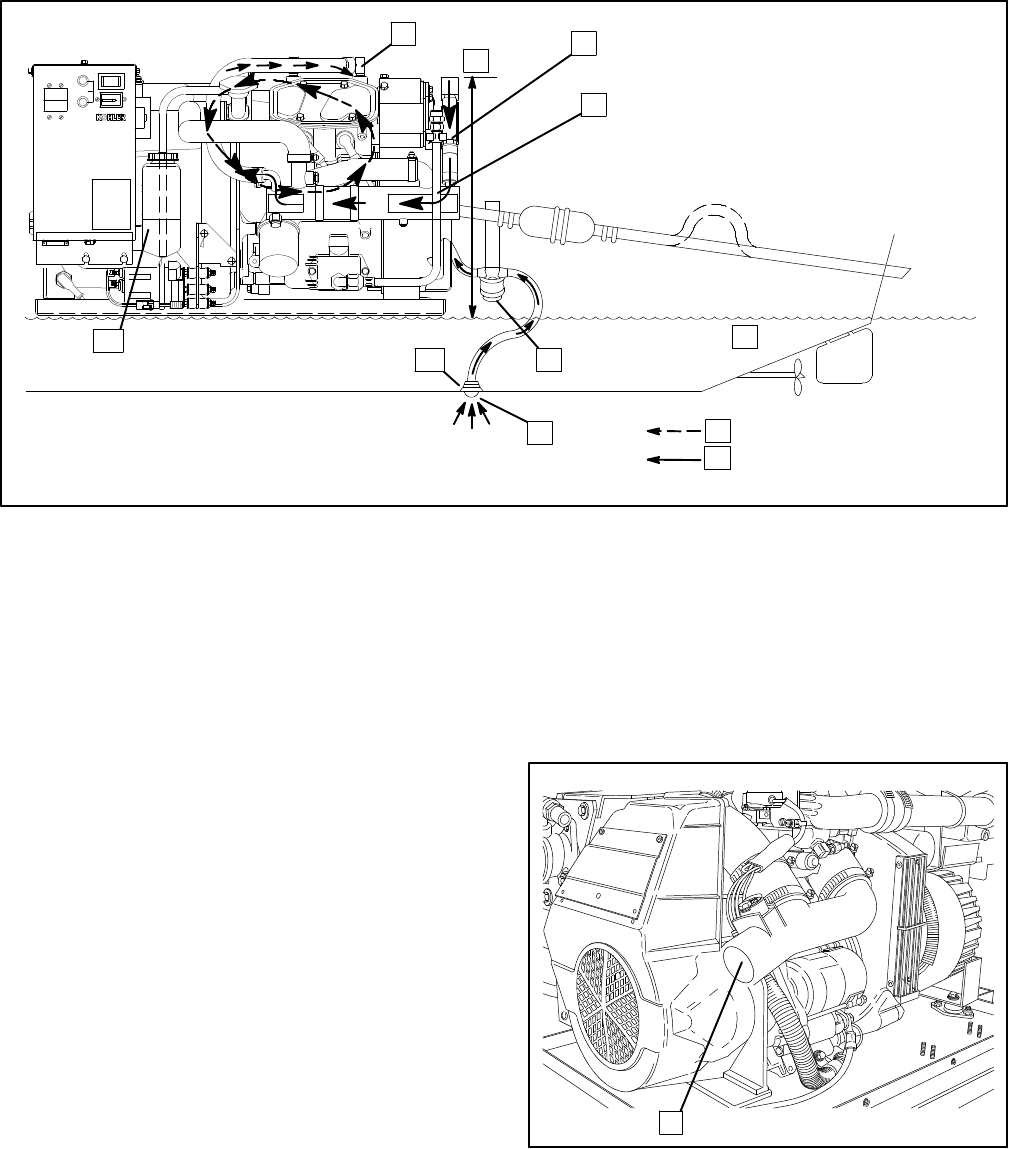
TP-5695 12/93 Installation 6-9
TOTALHOURS
00 000 1/10
10A
FUSE
BATT.
CHRG.
INPUT
NOTE
Usetwohoseclampsoneach
end ofall flexible exhaust
hoseconnections.
1.ExhaustManifold
2.3ft. (1m)Max.
3.Engine-Driven SeawaterPump
4.HeatExchanger
5.Waterline
6.SeawaterStrainer
7. IntakeStrainer
8.Engine Coolant
9.Seawater
10.Seacock
11.CoolantRecoveryTank
123
4
5
6
78
9
10
11
STOP/START
258000-D
Figure 6-15.Closed/HeatExchangerCooling System
ExhaustSystems
General
Water-cooledexhaustlinesshouldbeusedin all marine
installations.The hose used forthe lines should have a
2in.(51 mm)inside diameter.Keep the linesas short
andstraightaspossible.Theuseof two hoseclampson
each end of flexible exhausthoseconnectionsishighly
recommended.ABYCSafetyStandardsP-1.6.c
recommend a pitch ofatleast1/2in.(12.8mm)per
running foot(30.5cm).Useflexiblesteamhose
conforming toULStandard 1129 for“Engine wet
exhaustcomponents”between the mixing elbowand
the exhaustoutlet. Asilencershould be independently
mounted to eliminate any stress on the exhaustsystem
and exhaustmanifold/mixerelbow.See Figure 6-16 for
the exhaustconnection tothe mixerelbow.
11-894
1.Seawater/ExhaustOutlet
Figure 6-16.MixerElbow/ExhaustConnection

TP-5695 12/936-10 Installation
Locatetheexhaustoutletatleast4in.(10cm)abovethe
waterlinewhenthecraftisloadedtomaximumcapacity.
Usuallyaflapperisinstalled atexhaust(transom)outlet
topreventwaterbackup infollowing seasorwhen going
astern(backward).
WARNING
Carbon monoxide.
Cancause severenausea,fainting,ordeath.
The exhaustsystem mustbe leakproofand
routinelyinspected.
Carbon monoxide cancause severenausea,
fainting,ordeath.Usethe following precautionswhen
installing and operating generatorset. Carbon
monoxide isparticularlythreatening inthatitisan
odorless,colorless, tasteless,nonirritating gas.Be
especially careful ifoperating the generatorwhen
moored oranchored undercalmconditionsasgases
mayaccumulate.Ifoperating the setdockside,moor
yourcraftsothatthe exhaustdischargesonthe leeside
(the side sheltered fromthe wind),and always be
mindfulofothers—makesureyourexhaustisdirected
awayfromotherboatsand occupied buildings.Do not
install exhaustoutletwhere exhaustcan be drawn
through portholes,vents,orairconditioners. If
generatorset’sexhaustdischarge holeisneartoyour
craft’swaterline,DONOTOVERLOAD CRAFTso asto
close or restrictexhaustdischarge hole.
TOTALHOURS
00 000 1/10
10A
FUSE
BATT.
CHRG.
INPUT
NOTE
Usetwo hoseclampson each end of
all flexible exhausthoseconnections.
1.HeatExchanger
2.ExhaustManifold
3.Engine-Driven SeawaterPump
4.3ft. (1m)Max.Lift ofSeawaterPump
5.Silencer (CustomerSupplied)
6.ExhaustHoseSlope 0.5in.(1.3cm)perft. (30.5cm)
7.SlightLift ImprovesSilencing (Keep BelowLevel
ofExhaustManifoldOutlet)
8.4in.(10 cm)Min.ofExhaustLine AboveWaterline
9.Waterline
10.SeawaterStrainer
11. IntakeStrainer
12.10 ft. (3m)Max.Between ExhaustOutletand Silencer
13.Seacock
14.CoolantRecoveryTank
11
NOTE
Data givenisapplicableto
side-exhaustinstallations.
12
5
6
7
8
9
10
4
12
STOP/START
14 13
3
258000-D
Figure 6-17.TypicalAbove WaterlineInstallation
Exhaustsystemguidelinesforvariousgeneratorset
locationsfollow.Where exhaustlineswouldrequire
passage through bulkheads,itmaybe more practicalto
use port(left)orstarboard(right)side exhaustoutlets.
Thiswould be especiallytrue wherelong exhaustlines
tothe transom(rear) couldcause excessive back
pressure. Information and illustrationsofstern(rear)
exhaustinstallationsalso applytoside exhaust
installations.Should anyinformation regarding
installation conflictwithU.S.C.G.Regulations,
appropriateRegulations shouldbefollowed.
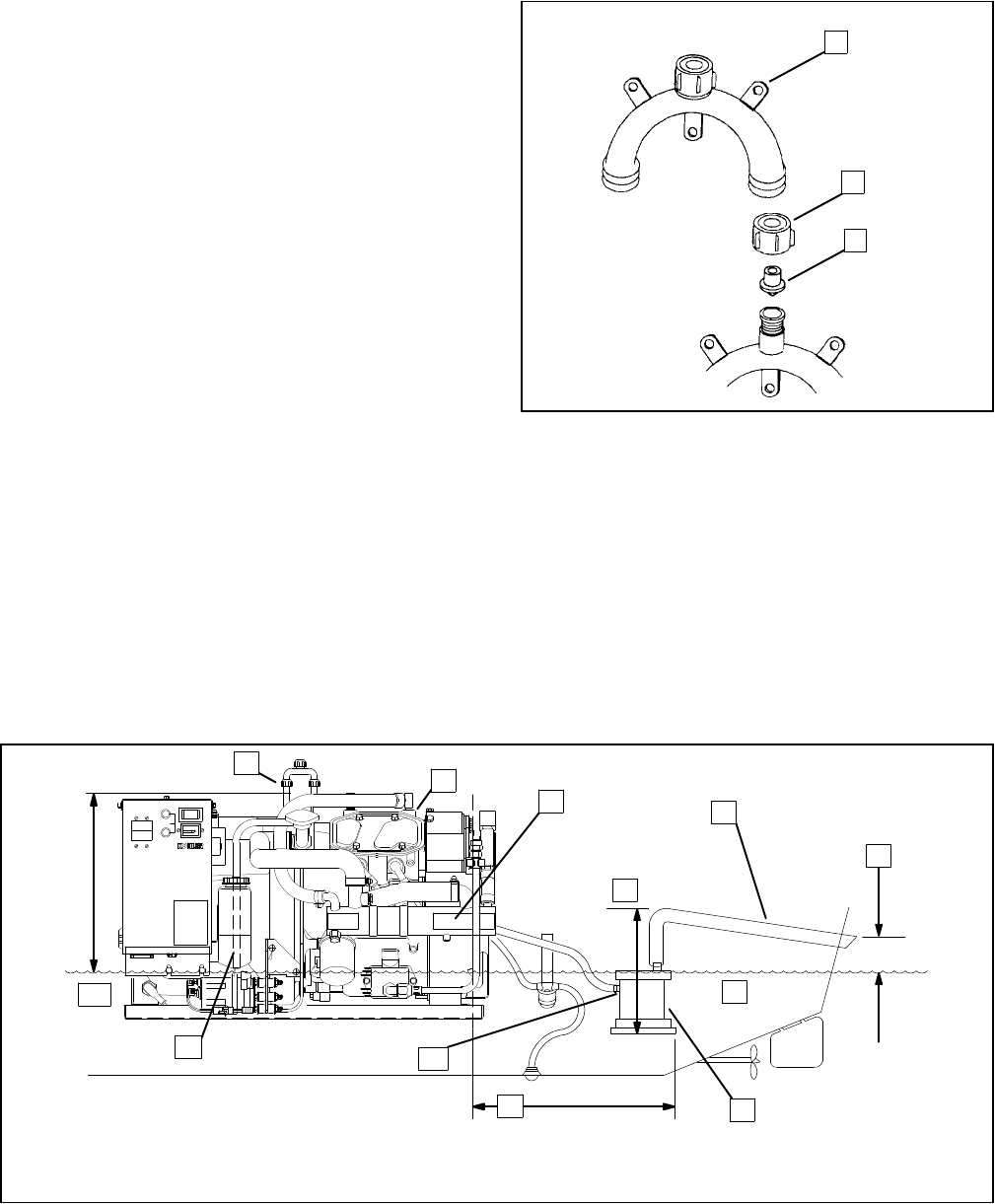
TP-5695 12/93 Installation 6-11
Above Waterline
In addition toconsiderationsdescribed earlier,a
customer-supplied silencershouldbeinstalled withits
outletatamaximumof10 horizontalft. (3m)fromthe
centerof the engine’sexhaustoutlet(see Figure 6-17).
Atypicalsilencershouldbemounted withthe inletand
outletleveland withthe drain plug down.The silencer
mayrequiretwosupporting bracketsorhangerstraps
forinstallation tostringersorothersuitablestructure.
Any“lift”inthe exhaustlinetoimprovesilencingmustbe
belowthe engine exhaustmanifold outlet.
Mid/BelowWaterline
U.S.C.G.Regulationsrequirethatan anti-siphoning
provision be used to preventraw waterentryintothe
engineiftheexhaustmanifoldoutletislocated lessthan
9in.(23cm)abovethewaterlinewhenthecraftisloaded
tomaximumcapacity. Install asiphon break,see
Figure 6-18,atleast1ft. (31 cm)abovewaterline as
showninFigure 6-19.
1
2
3
1.Mounting Base
2.Retaining Cap 3.Reed ValveAssembly
1-779
Figure 6-18.Siphon Break Components
The siphon breakmustbe located atleast1footabove
the waterline atmaximumvesselcapacitybetween the
heatexchangerand waterelbow(three-wayfittings).
The siphon breakand fitting mustbe supported to
maintainproperpositionandfunction.Thesiphonbreak
shouldbemounted directly verticalofits connection to
generatorsetwhere possible.Otherwise,aslightoffset
isallowabletoclearstringersorotherpermanent
structures.
1.Siphon Break
2.ExhaustManifold
3.HeatExchanger
4.4ft. (1.2m)Max.
5.ExhaustHoseSlope 0.5in.(1.3cm)perft. (30.5cm)
6.4in.(10 cm)Min.
7.Waterline
8.Silencer (CustomerSupplied)
9.10 ft. (3m)Max.
10. Install OptionalWaterLock Here
11.CoolantRecoveryTank
12.1ft. (30.5cm)Min.
TOTALHOURS
00 000 1/10
10A
FUSE
BATT.
CHRG.
INPUT
NOTE
Usetwo hoseclampson
each end ofall flexible
exhausthoseconnections.
NOTE
Data given isalso applicable
toside-exhaustinstallations.
4
5
6
7
8
9
10
11
12
STOP/START
123
258000-D
Figure 6-19.TypicalMidand BelowWaterlineInstallation
TP-5695 12/936-12 Installation
Atypicalsilencershouldbemounted no morethan 4 ft.
(1.2m)belowthe highestpointinthe exhaustline.
Attachaseparatewood mounting baseto hull stringers
orothersuitablestructure.Then securethe silencerto
hull using silencermanufacturer’srecommendation.Be
surethe silenceroutletisnotmorethan 10 horizontalft.
(3m)fromthe engine exhaustmanifold outlet. UL
marine exhausthoseshould be used.
ElectricalSystems
AC VoltageConnections
WARNING
Explosion.
Gasoline vapors cancause explosion and
severeinjuryordeath.
Beforestarting generatorset, operate blower4
minutesand check engine compartment for
gasoline vapors.
Explosive fuelvapors cancause severeinjuryor
death.Gasoline vapors can explode and can cause
death orsevereinjury.USCGRegulation 33CFR183
requiresall electricaldevices(ship-to-shoretransfer
switch,remotestartpanel,etc.)tobe“ignitionprotected”
whenusedinagasoline(gaseous)-fueledenvironment.
These electricaldevicesare not“ignition protected”and
are notcertified to operatein a gasoline
(gaseous)-fueled environmentsuch asengine roomor
nearfueltanks.Acceptablelocationswould be
wheelhouseorotherlivingareasshelteredfromrainand
watersplash.
WARNING
Hazardous voltage.
Do notoperate generatorsetwithoutall guards
and electricalenclosuresin place.
Moving rotor.
Cancause severeinjuryordeath.
Hazardous“backfeed”voltage cancause severe
injuryordeath.Do notconnect to anybuilding/marina
electricalsystemwithoutconnecting through an
approved device and afterbuilding mainswitchisopen.
Backfeedconnectionscancauseseriousinjuryordeath
to utilitypersonnelworking torepaira poweroutage
and/orpersonnel inthe vicinity.Unauthorized
connection maybe unlawful insomestatesand/or
localities.Aship-to-shoretransferswitchmustbe
installed to preventinterconnection ofgeneratorset
powerand shore power.
ACconnectionsto generatorsetaremade inside the
controllerbox.Thegeneratorsetisusually connectedto
aship-to-shoretransferswitchwhich allowsthe use of
shore/utilitypowerwhendocked orgeneratorsetpower
whendockedoratsea.Thewiringisthenconnectedtoa
maincircuitbreakerbox(panelboard)which distributes
branchcircuitsthroughout the craft. See Section 5.
Wiring Diagramsfor reconnectabilityofgeneratorset.
Installation inSteelor
AluminumVessels
Installation ofa generatorsetinavesselconstructed of
amaterialcapable ofconducting current(e.g.: steelor
aluminum)is subject toconsiderationsnotnormally
encountered infiberglass orwood vessels.These
differencesinclude equipmentgrounding,grounding of
neutralconductors,ground faultprotection,and
isolation ofgalvanic currents.
Whilethe scope of thesetopics istoo extensiveto be
fullydiscussed here,referencestothe appropriate
governing bodieswill be identified forfurther
investigation.
The information provided hereisintended toserve asa
guideline to boatmanufacturersand generatorset
installers.Thisinformation isnotintended orimplied to
be limited tothesesourcesand is subject torevision by
the appropriate governing bodies.
Priortoinstalling the generatorset, check the wiring
diagramsto becomefamiliarwiththe electricalsystem.
Generatorsetsinstalled in pleasurecraft are governed
bythe U.S.CoastGuard and the American Boatand
YachtCouncil, Inc.CompliancewithU.S.CoastGuard
RegulationsgiveninTitle33,Part183mustbefollowed.
Generatorsetsinstalled in pleasurecraft require a
grounded neutralsystemas specified inABYCE-8.4.b.
Variouswiring configurationsareillustrated inABYC
StandardsE-8.22 through E-8.29.Grounding of
appliancesand equipmentis covered inABYCE-8.12.
Galvanic corrosion prevention bymeansofgalvanic
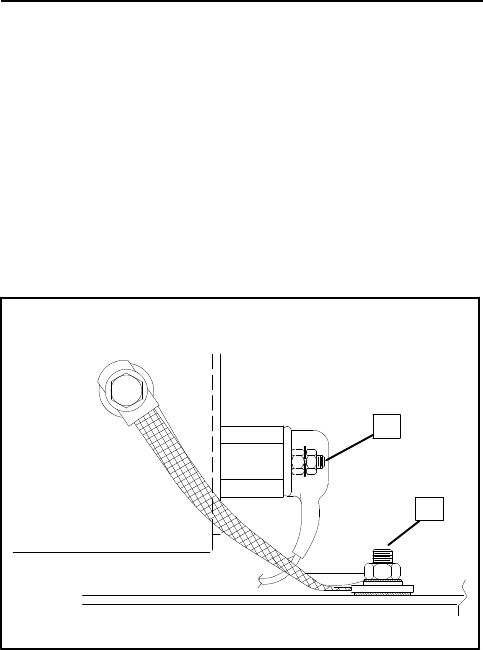
TP-5695 12/93 Installation 6-13
isolatororisolation transformerisreferenced inABYC
E-8.20 and ABYCE-8.11.
Generatorsetsinstalled incommercialvesselsare
governedbyU.S.CoastGuardRegulations,Title46,the
American Bureau ofShipping,and Lloyd’sRegisterof
Shipping.Grounding ofequipmentis covered inABS
35.9.6 and Lloyd’sPart6,Chapter2-1,Section 1.3.The
typesofpermissible neutralgrounding ofgenerating
equipmentarereferenced inABS 35.125 and 35.95.1
andin Lloyd’sPart6,Chapter2-1,Section14.4.Ground
faultprotection information can be found in Lloyd’sPart
6,Chapter2-1,Section 14.5 and Part6,Chapter2-2,
Section 13.6.
Battery
BatteriesandtheirinstallationmustconformtoU.S.C.G.
Regulations183.420 (a)through (g).Generatorsets
should use batteries separatefromthe propulsion
engineswheneverpossible.Boththe generatorsetand
the propulsion engines’ starting/charging systemsmust
haveacommon negative(--) ground.
U.S.C.GRegulation 183.415,Grounding,requiresa
common conductortobeconnected to each grounded
crankingmotorcircuit.Thisconductorshouldbesizedto
matchthe largerof the engines’two battery cables.
(Cablesizesforgeneratorsetbattery connectionsare
given inFigure 6-20.)Thisrequirementpreventsthe
starting motorcurrent fromusing alternative electrical
paths shouldthe cranking motorground circuitbe
restricted oropen due to oxidation orloose hardware.
These alternative electricalpathsinclude metallicfuel
lineswhichcan poseafire hazard.See Figure 6-21 for
battery connectionsto generatorset.
Distance Between
GeneratorSetand
BatteryAt0° F
(--18° C)
Cable
Size
(AWG)
At32° F
(0° C)At75° F
(24° C)
40 ft. (12.2m)00 0 1
30 ft. (9.1m)012
25 ft. (7.6m)124
20 ft. (6.1m)226
15 ft. (4.6m)246
10 ft. (3.0m)468
5ft. (1.5m)668
2.5ft. (0.8m)888
Figure 6-20.BatteryCableSizes
1.BatteryPositive(+)
Connection 2.BatteryNegative(--)
Connection
1
2
ADV-5792-D
Figure 6-21.BatteryConnection Bracket
Wiring
All wiring mustbe stranded copper.Wire gaugesand
insulation,conductortemperatureratings,sheath
stripping,conductorsupportand protection,conductor
terminalsand splices,and overcurrentprotection
(circuitbreakers, fuses)mustconformtoU.S.C.G.
Regulations183.425 through 183.460.Userubber
grommetsand cableties,asnecessary, to protectand
securewiring fromsharp objects,exhaustsystem,and
anymoving parts.
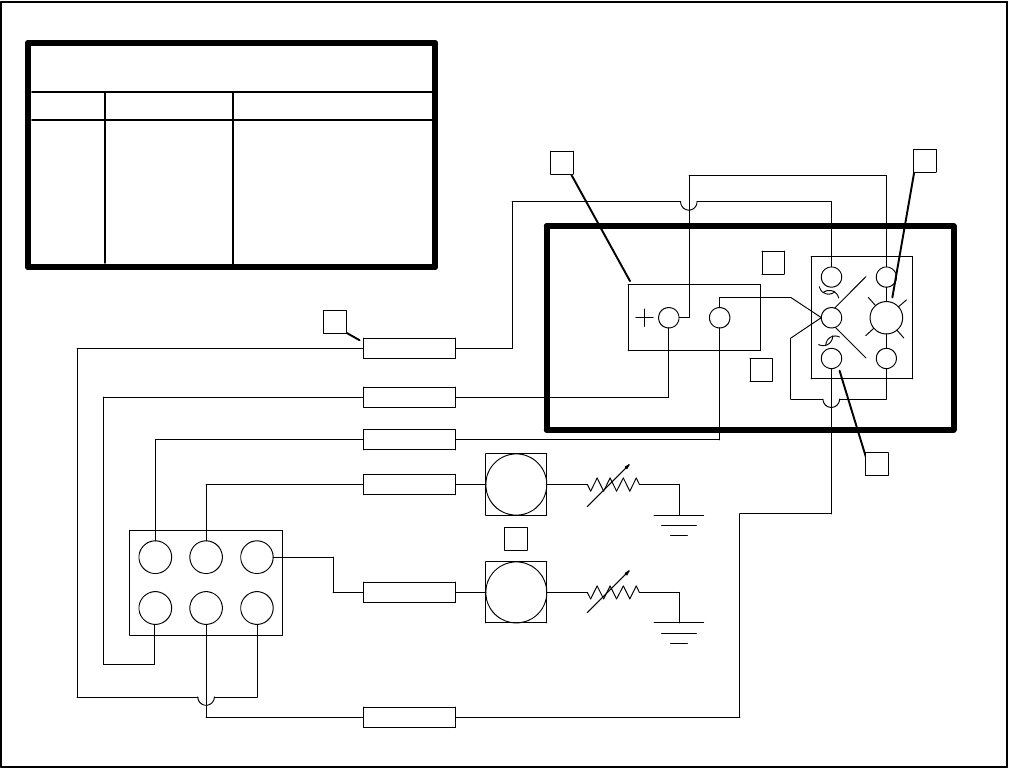
TP-5695 12/936-14 Installation
RemoteStartSwitchConnection
Kohleroffers severalremote panelsforconnection to
the generatorset. See Accessoriesforfurtherdetailed
description.Awiring harness withaconnectorkeyed to
the controllerbox connectorisavailabletoconnect
these panelstothe generatorset. The otherend of this
harness haspigtailswhichcan be used if the installer
electsto usejustastart-stop switch orseparatelights
and hourmeter.See Figure 6-22.
NOTE
If gaugesareto be used, theremustalso be generator
setsenders.Sendersare optionalon these generator
sets.Gaugesand sendersare available as service
itemsfroman authorized Kohlerservice
dealer/distributor.
WT
OP
123
456
J3
LeadDesignations
Pin Lead Function
J3-1Black Ground (--)
J3-2Tan WaterTemp.Ga.
J3-3 Lt. Blue Oil PressureGa.
J3-4VioletGen.“ON”(+)
J3-5Yellow/Red Start
J3-6Grey/Black Stop
NOTE
All wireis16 gauge.
Tape toinsulate all
unused lead ends.
1
23
4
6
7
5
1.UseInsulinkorSolderConnection (Tape toInsulate)
2.Hourmeter
3.“ON”Light
4.Stop
5.Start
6.RockerSwitch
7.GaugesSenders
Figure 6-22.RemoteControlPanelWiring
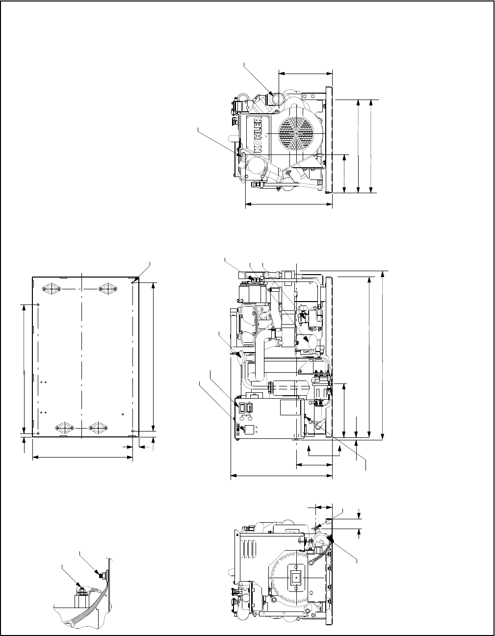
TP-5695 12/93 Installation Drawings7-1
Section 7. Installation Drawings
ADV-5792-D
VIEW A--A
MOUNTING PATTERN
EQUIVALENT.
ARE MILLIMETER
DIMENSIONS IN ( )
NOTE:
WITH HUSH COVER.
5/6.5 SUPPLIED STANDARD
WITH HEAT EXCHANGER
WATER--COOLED
IGNITION PROTECTED
4/6.5KW 60HZ. GASOLINE MARINE
3.5/5KW 50HZ. GASOLINE
A
A
REMOTE
CONNECTION
SEA WATER INLET
.75 (.19) I.D. HOSE
1/4 STUD FOR
BATTERY CONNECTION
(POSITIVE)
5/16 STUD FOR
BATTERY CONNECTION
(NEGATIVE).
1.65
(42)
.62
(16)
2.69
(68)
9.13
(232)
21.20
(538)
1.0
(25)
1.0
(25)
15.50
(394)
GROUND LUG
WATER COOLED EXHAUST
OUTLET FOR 2.0 (51) I.D.
RUBBER HOSE
14.19
(360)
6.34
(161)
FUEL INLET
1/4 N.P.T. 15.43
(392)
17.50
(445)
OIL DRAIN
8.77
(223)
27.87
(708)
26.44
(672)
.44
(11)
16.60
(422)
5.89
(150)
24.44
(621)
ENGINE
.406 DIA. (4) HOLES
(10)
CIRCUIT BREAKERS (OPTIONAL)
START/STOP SWITCH
ENGINE COOLANT
CHECK AND FILL
ENGINE OIL
CHECK AND FILL
OIL FILTER
C
L
Sheet 1
Figure 7-1.Dimension Drawing--3.5CFZ,4CZ,5CFZ,and 6.5CZ
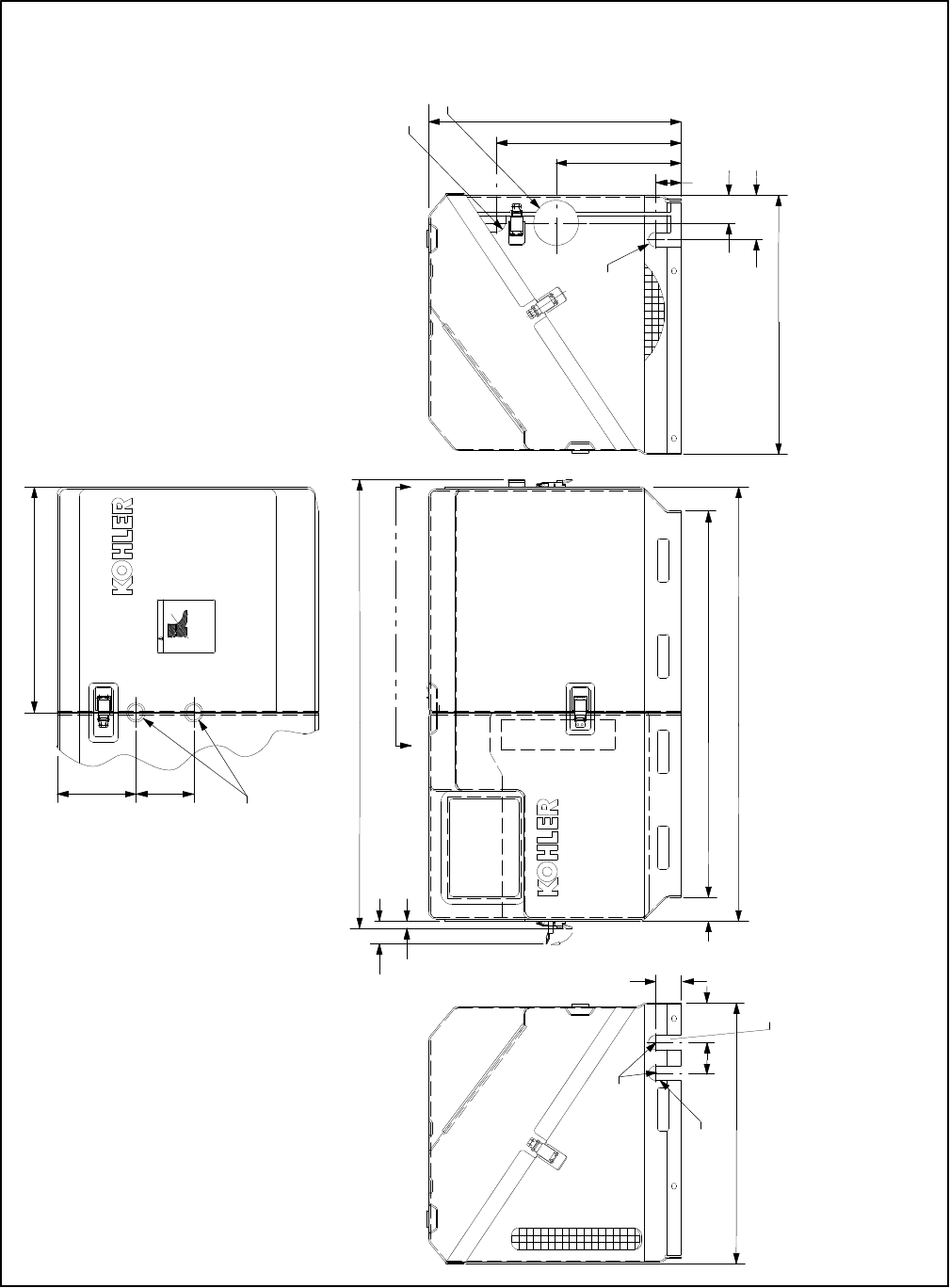
TP-5695 12/937-2Installation Drawings
ADV-5792-D
A A
VIEW A--A
KIT # 267994 (4 PIECE COVER).
SOUND SHIELD SERVICE
WITH SOUND SHIELD.
5/6.5KW SUPPLIED STANDARD
MILLIMETER EQUIV.
DIMENSIONS IN ( ) ARE
NOTE:
31.07
(789)
1.75
(44)8.67
(220)12.82
(326)
3.12 DIA. (79)
EXHAUST
OUTLET
OPENING
1.92
(49)
1.57
(40)
.51
(13) TYP.
CLEARANCE REQ’D FOR
LATCH OPENING
3.07
(78)
17.86
(454)
.50 R.
(13)
OPENING FOR FUEL
INLET HOSE AND
BATTERY CONNECTIONS
OPENING FOR
A.C. LOAD LEADS
.625 R. (16)
SEA WATER INLET
MOUNTING LOCATION FOR
SIPHON BREAK ASSEMBLY.
DRILL (2) 1.00”DIA. HOLES
USING INDENTATIONS FOR
LOCATION. (OPTIONAL)
30.06
(764)
26.76
(680)
1.65
(42)
2 PLACES
18.10
(460)
.50 R. (13)
2.75
(70)
2.12
(54)
17.50
(445)
Do not use as a step.
267957
Standing on genset could
impair operation of unit.
CAUTION
15.62
(397)
4.00
(102)5.45
(138)
1.75
(44)
Sheet 2
Figure 7-2.Sound Shield--Optionalon 3.5CFZ and 4CZ;Standardon5CFZ and 6.5CZ
TP-5695 12/93 PartsOrdering Instructions8-1
Section 8.PartsOrdering Instructions
Forserviceorinformation,checktheyellowpagesofthe
telephone directoryunderthe heading
GENERATORS--ELECTRICorcontact the localmarina
fortheauthorizedKohlerservicedealer/distributorinthe
area.
KOHLER CO.KOHLER,WISCONSIN53044
PHONE414-565-3381
FAX 414-459-1646 (NorthAmerican Sales),
414-459-1614 (International)
FORSALES&SERVICEINU.S.A.&CANADAPHONE
1-800-544-2444
Amajorservicemanualand parts catalog maybe
ordered through an authorized Kohlerservice
dealer/distributor.When ordering,stateMODEL and
SPEC.numbersfromthe GeneratorNameplate.(See
NOTAG.)
In any communicationsregarding thisgeneratorset,
pleasereporttheMODEL,SPEC.andSERIALnumbers
asfound on the nameplate attached tothe generator
and engine.Enternumbersinspacesprovided below.
Thisinformation will enablethe authorized Kohler
service dealer/distributortosupplythe correctpartor
dataforthisparticularmodel.
ModelNo. ......................................
Specification No. ................................
SerialNo. ......................................
Engine No. .....................................

TP-5695 12/93 Operating HourService Log 9-1
Section 9. Operating Hour Service Log
The following isprovided to helpyou keep a cumulative
record ofoperating hourson yourgeneratorsetand the datesrequiredserviceswere performed.Enterhoursto
the nearestquarterhour.
OPERATINGHOURS SERVICERECORD
DATEHOURSRUN CUMULATIVE DATE SERVICE

TP-5695 12/93
PRINTEDIN U.S.A.
KOHLER CO. KOHLER,WISCONSIN53044
PHONE 414-565-3381
FAX 414-459-1646 (NorthAmerican Sales), 414-459-1614 (International)
FOR SALES & SERVICE IN U.S.A.& CANADA PHONE 1-800-544-2444
