Kondo Kagaku T090515 EX-5UR for radio controlled models User Manual EX5UR UserMan
Kondo Kagaku Co., Ltd. EX-5UR for radio controlled models EX5UR UserMan
EX5UR UserMan
MADE IN JAPAN 1
Though developed as a well-balanced and controllable entry model, EX-5UR ultra high-response transmitter uses
2.4GHz as a frequency and allows simultaneous running without checking unused band. This high standard model
is widely recommended from beginners to enthusiasts. 27 functions allows you to make detailed settings for R/C
race. This set is available either "Electronic Speed Controller Set" for electric powered cars or "2-servo set" for gas R/C
cars. Refer to the instructions according to your R/C car.
● For gas cars
● For electric cars
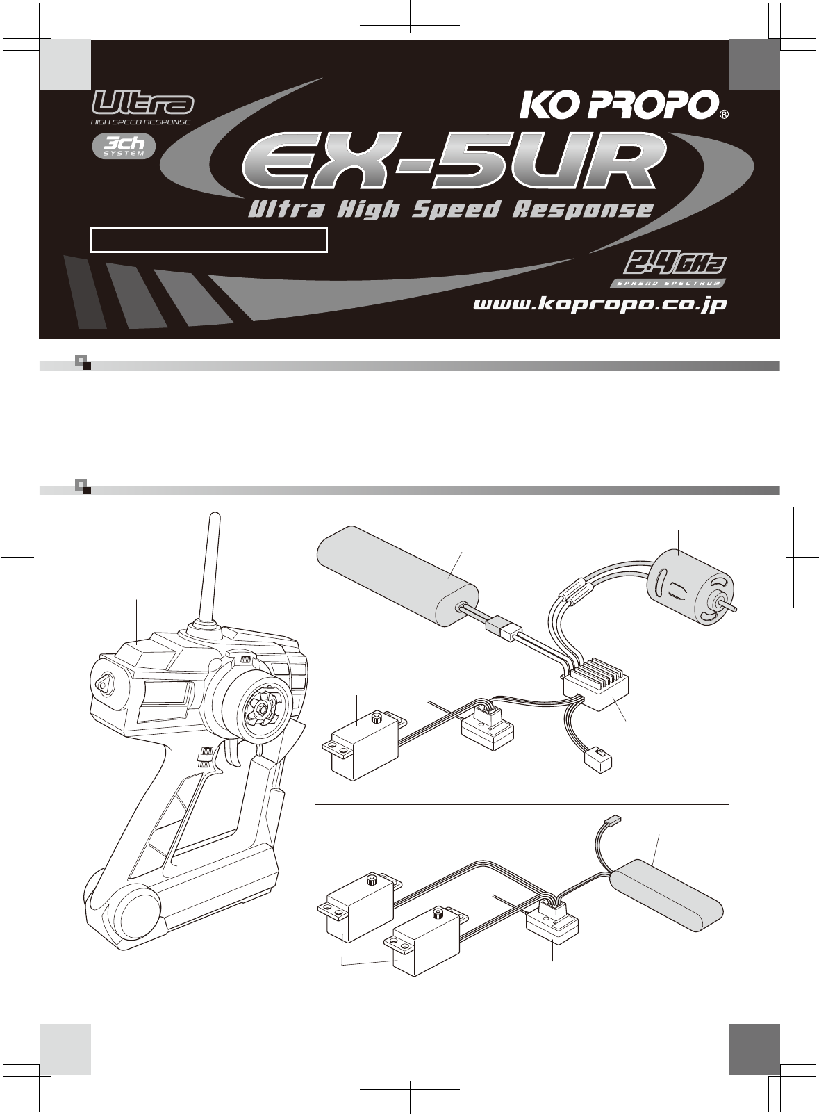
Set components and cable connection
●Running battery (not included)
●Receiver (KR-407S)
●Motor (not included)
●ESC (Speed controller)
●Receiver battery
(not included)
●Servo
●Servo
●Transmitter
(EX-5UR)
●Servo horn
●Servo grommet
●Digital servo sticker
●Receiver connector cap
●Receiver (KR-407S)
Instruction manual
Thank you for purchasing EX-5UR. Please read and fully understand the instructions prior to use R/C model.
EX-5UR Features
When using units not included in the set, be sure to use products compatible with
"Ultra High Speed Response". Please refer to our website for details
)pj.oc.oporpok.www( (Japanese only)
Caution!
16P 製本 1C
2
2
With the nature of radio controlled model, improper usage may result in serious accidents. In order to avoid these
circumstances, please read following contents before use. We cannot be held responsible for problems
encountered when not complying with these cautions and notices.
Warning!
Failure to observe the matter discussed in such an item poses a serious threat of death or severe injury.
Caution!
Failure to observe the matter discussed in such an item poses a possibility of injury or damage to the equipment or property.
Caution when installing units
Notes on driving
Notes after driving
Warning!
Enforcement matters
Warning!
Enforcement matters
Caution!
Enforcement matters
Caution!
Enforcement matters
Warning!
Enforcement matters
Warning!
Prohibited matters
Warning!
Prohibited matters
Caution!
Prohibited matters
For safe operation
■ For safe operation
●Make sure metal parts do not come in direct contact to model (chassis/ship hull) by vibration.
※Noise of metal parts may result in malfunction of receiver, and the model may run out of control
●Do not cut or bundle receiver antenna with other cables.
※It may result in decreasing the sensitivity of receiver and may result in the model running out of control.
●Note polarity when installing batteries to transmitter and receiver. ※It may damage R/C units.
●Be sure to connect receiver, servo and switch connectors correctly.
※If connections are loosened by vibration, the model may run out of control.
●Attach receiver using thick double-sided tape to avoid direct contact with other parts.
※Strong shock and vibration may result in the model running out of control.
●Operate servo to check that there are no unnecessary forces onto the push rod.
※It may damage the servo or increase the consumption of batteries.
●Make sure to use rubber grommet to attach servo and be sure that the servo is not touching mecha-
nism plate directly.※The vibration may damage the servo and the model may run out of control.
●Use genuine KO transmitter, receiver, servo, speed controller, and optional parts.
※We cannot be held responsible for problems encountered when using with other maker's products.
●Do not use in thunderstorms.※There is possibility of lightning striking the antenna.
●Do not use in the rain or in a location where water might get in.
※The unit may become wet in and run out of control.
●Do not use in the following places.
1. Near to other radio control circuits (within 3km)
2. Near to people or on the street.
3. Near electric wires or communication facilities.
※In the case of the model running out of control, dangerous situations will occur.
●Do not run the model when you experience difficulties in concentration through tiredness, alcohol or
medication.※The miss-judgment may result in accidents.
●Do not allow fuel or exhaust to touch plastic parts ※It may attack plastic.
●Make sure that model memory is matched to the models currently running.
※Otherwise, it may cause car to run out of control.
●Make sure to stop engine (disconnect motor cables) before making function change.
●Do not touch engine, motor or speed controller immediately after running.
※They are hot and can cause burns
●Transmitter emits a high-frequency energy from antenna. The antenna may cause a kind of stimulus if
touched by fingers.
●Always turn on the transmitter first, followed by the receiver. When turning off, turn off the receiver first,
followed by the transmitter.
●Dismantling of transmitter is prohibited and it can be punished. Disassembly and modification of all
units may cause accidents such as a short circuit. Also, repair service may not be accepted in this case.
●Do not use in aircraft, hospital, near electrical equipment such as fire alarm or medical equipment. It
may cause malfunction and result in serious accidents. Turn off the transmitter immediately if it effects
on other wireless or electric appliances.
●2.4GHz transmitter must be registered in the Japan Radio Control Safety Association. This product is
pre-registered. Note that transmitter without registration is regarded as violations of radio law.
●When using with electric powered R/C car, make sure to remove batteries after running.
※If the power turns on accidentally, it may cause the model to run out of control or fire disaster.
●Keep transmitter, batteries and model out of reach of children.
※Chemical material may cause personal injury.
●Remove batteries from transmitter when not in use for a long time.
※If you leave batteries in the transmitter, leakage may damage transmitter.
●Avoid storing transmitter and receiver in the following places.
1. Extremely hot or cold places (+40C or ‒10C)
2. Direct sunlight
3. High humidity places
4. Vibration
5. Dusty places
※If you store the unit under these circumstances, it may result in deformation or damage to the unit.
3
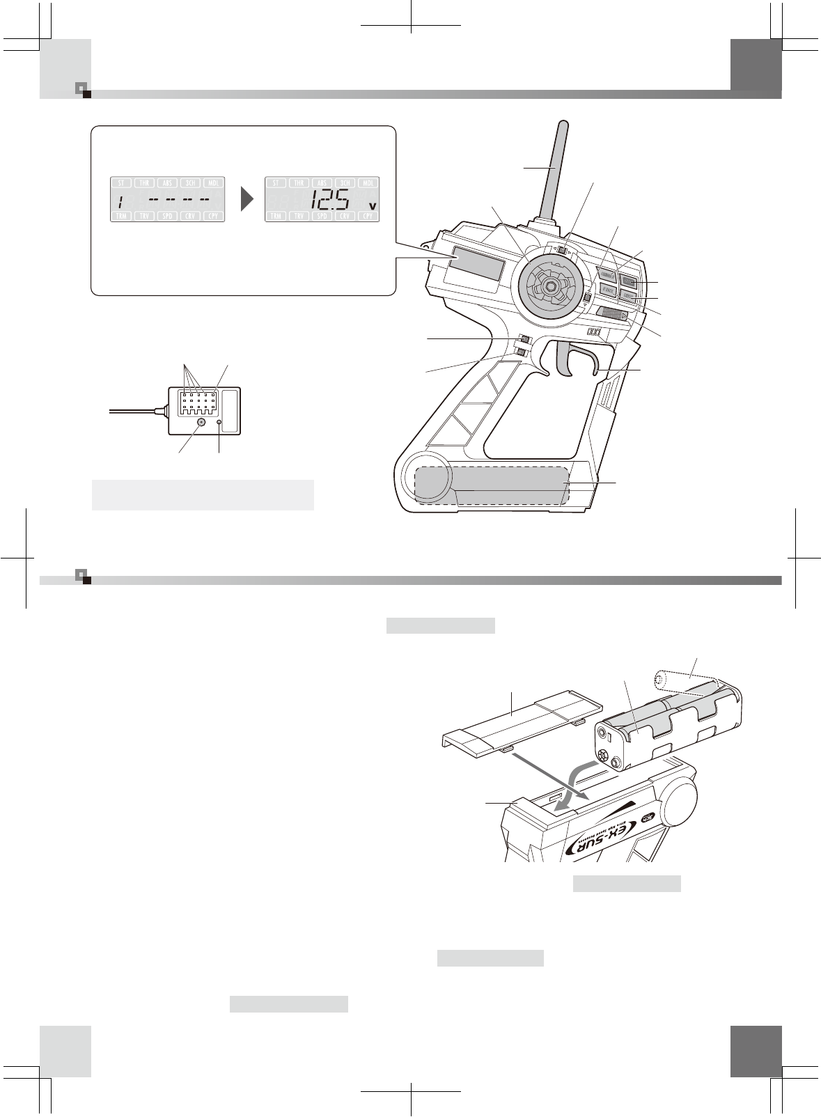
Name of parts
Unit preparation
※Alarm sounds when batteries are depleted. Install fresh
batteries as soon as possible to keep radio power.
Model name (MENU26) Voltage Antenna
LCD display (factory setting)
Steering wheel
Throttle trigger
Power switch
Foward key
Back key
+/ Enter key
−/ Cancel key
ET1 lever
(Steering trim)
ET2 lever
(Throttle trim)
ET3 lever
(Steering travel)
ET4 lever
(3ch control)
LED indicator
Set button
Battery connector
Channel 1∼4 connector
●Transmitter
(EX-5UR)
●Receiver(KR-407S)
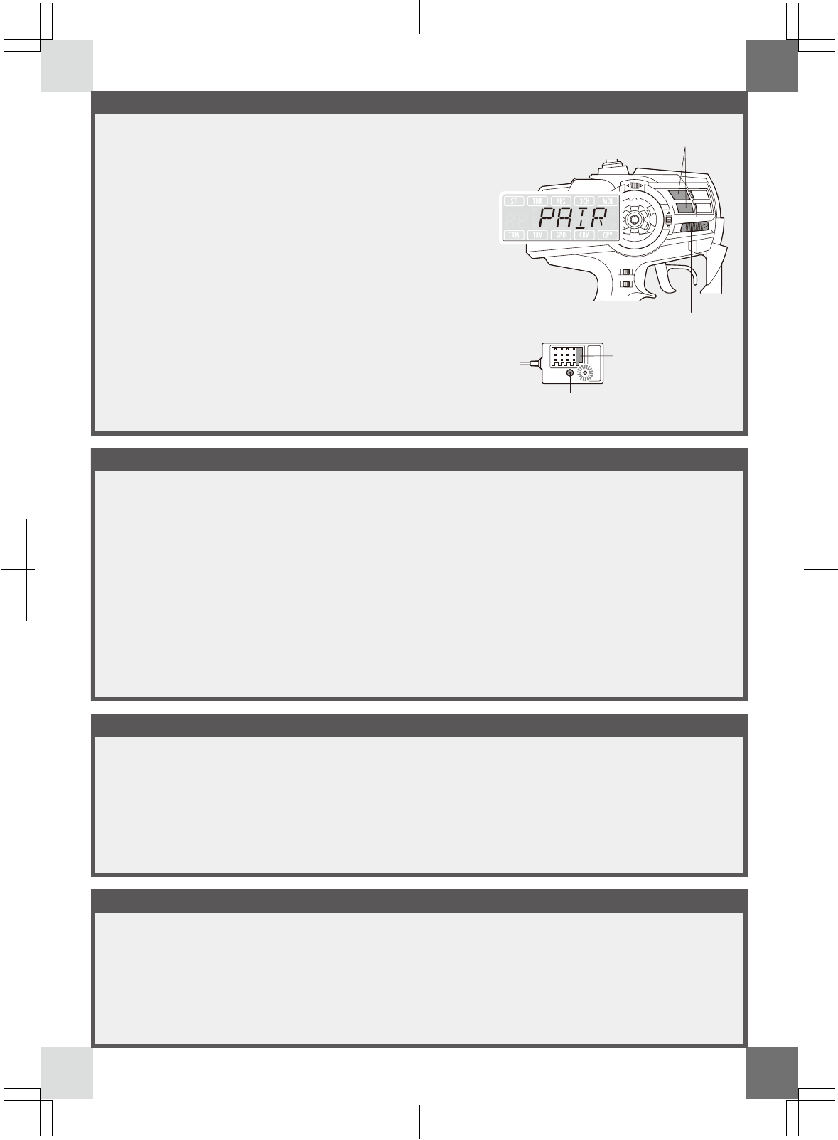
※EX-5UR requires “pairing” to register the transmitter ID number to the receiver the first time you use.
When operating several receivers (cars) using one transmitter, perform "pairing" for each receivers only first time you use.
Battery box (inside)
※Note polarity and install fresh batteries. Depleted batteries
may deteriorate radio power and cause problems.
※Read instructions included with servo and speed controller before connection and usage.
※Regarding servo and ESC, please refer
each set-supplied instruction manual.
Battery box
R6/AA/UM3 battery
Transmitter (bottom)
Battery cover
Adjust steering and throttle/brake settings ←Refer to P.5
4.
Adjust failsafe ←Refer to P.15
5.
Register the transmitter to the receiver to complete “pairing”←Refer to P.5
3.
Install batteries (R6/AA/UM3 size batteries x
8) to transmitter, then install running battery
to electric R/C car. For gas R/C car, install
receiver batteries.
2.
Install receiver, servo, ESC (when using with electric car) and connect cables. Install
receiver noting anti-noise measures. ←Refer to P.4
1.
LCD indicates voltage after a certain period of time.
■ Name of parts/Unit preparation
4
4
Carbon chassis
Assume that all areas where large currents are
flowing are generating noise! Locate antenna cables
and receiver as far away from the motor, ESC,
silicone cords as possible. (Materials such as metal
or carbon chassis also conduct noise)
R/C model is controlled by radio wave. Therefore,
anti-noise measures are the most important factor.
Take measures to ensure optimum performance of
your R/C model and driving technique.
Notes on installing receiver (anti-noise measures)
When fixing the receiver to the chassis or on the
mechanism deck, use more than 2 layers of double-
sided tape to avoid direct contact with chassis.
Chassis and mechanism deck (especially carbon
material) can also conduct noise. Making space
between receiver with them is recommend to ensure
protection against noise.
Raise antenna cable vertically and set as high as
possible. Pass cable into antenna pipe to protect
from damage. Be sure that the cable projects a bit
from antenna pipe. Installing antenna holder far away
from receiver may deteriorate radio sensitivity.
Locate antenna holder as near to the receiver as
possible. Make sure that the antenna cable does not
come in direct contact with chassis, mechanism
plate or other noise sources. Make sure to use
plastic antenna pipe and mount. Do not use metal
antenna mount as it easily conducts noise and result
in trouble.
Engine vibration may damage the servo. Make sure to attach
grommet (receiver holder) to reduce vibration. Do not attach
directly to chassis or mechanism plate using double-sided tape.
The installation position should be as far as possible from heat
from engine or exhaust.
Battery
receiver
ESC Silicone cords
motor
Plastic antenna pipe Plastic antenna pipe
Plastic holder
Grommet
Aluminum holder Aluminum holder
Piano wire
Double sided tape
FRP or plastic holder
can be used.
Soldering lug plate
Locate antenna cable as far away from noise source!
●Fixing receiver to carbon chassis
●Antenna installation
●Attaching to a gas car
※Note receiver LED position when installing.
※Note receiver LED position when installing.
■ Notes on installing receiver (anti-noise measures)
Be careful of noise!
※Do not cut or bundle antenna cable.
(It may result in breaking of wire and deteriorate performance)
NOISE
NOISE
NOISE
NOISE
NOISE
NOISE
NOISE
NOISE
NOISE
NOISE
NOISE
NOISE
NOISE
NOISE
NOISE
NOISE
NOISE
NOISE
NOISE
NOISE
NOISE
NOISE
5
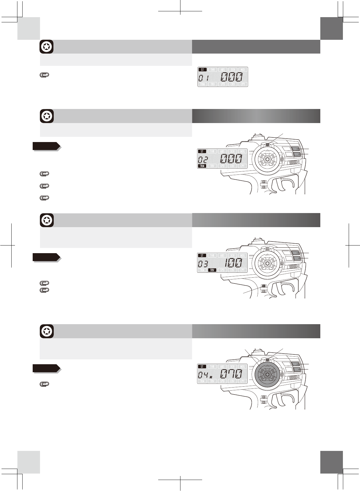
Adjusting turning angle of the steering servo.
① Adjust “
MENU
02: Steering trim” to 0 (default setting)
② Adjust "
MENU
08: Steering sub-trim" so that the car run straight with the steering in neutral.
③ Operate steering wheel. Make sure that the setting does not lock the linkage. In this case,
reduce values in "
MENU
03: Steering travel".
If turning angle is not enough, adjust each left and right angle at the maximum in "
MENU
04:
Steering balance R" and "
MENU
05 steering balance L".
▶How to pairing
▶Adjusting steering
1. Forward key + Back key
2. Power switch
2. Power
1. Set button
Register receiver to the transmitter
①
Hold both Forward and Back keys and switch transmitter on.
② "PAIR" (blinking sign) will be displayed on the LCD
screen and alarm sounds.
③ Blinking and alarm stops after approx. 5 seconds.
Then LCD screen displays “PAIR”.
Now the transmitter is ready.
④
Move receiver close to the transmitter (approx. within 1m)
⑤ Hold set button of the receiver then switch on.
⑥ Release set button. Receiver LED indicator turns on
after pairing is completed. Switch off both transmitter
and receiver.
▶Check movement
① Switch on the transmitter first, then switch on the
receiver. Confirm that the receiver LED indicator lit up.
② Check movement of the servo and the amplifier.
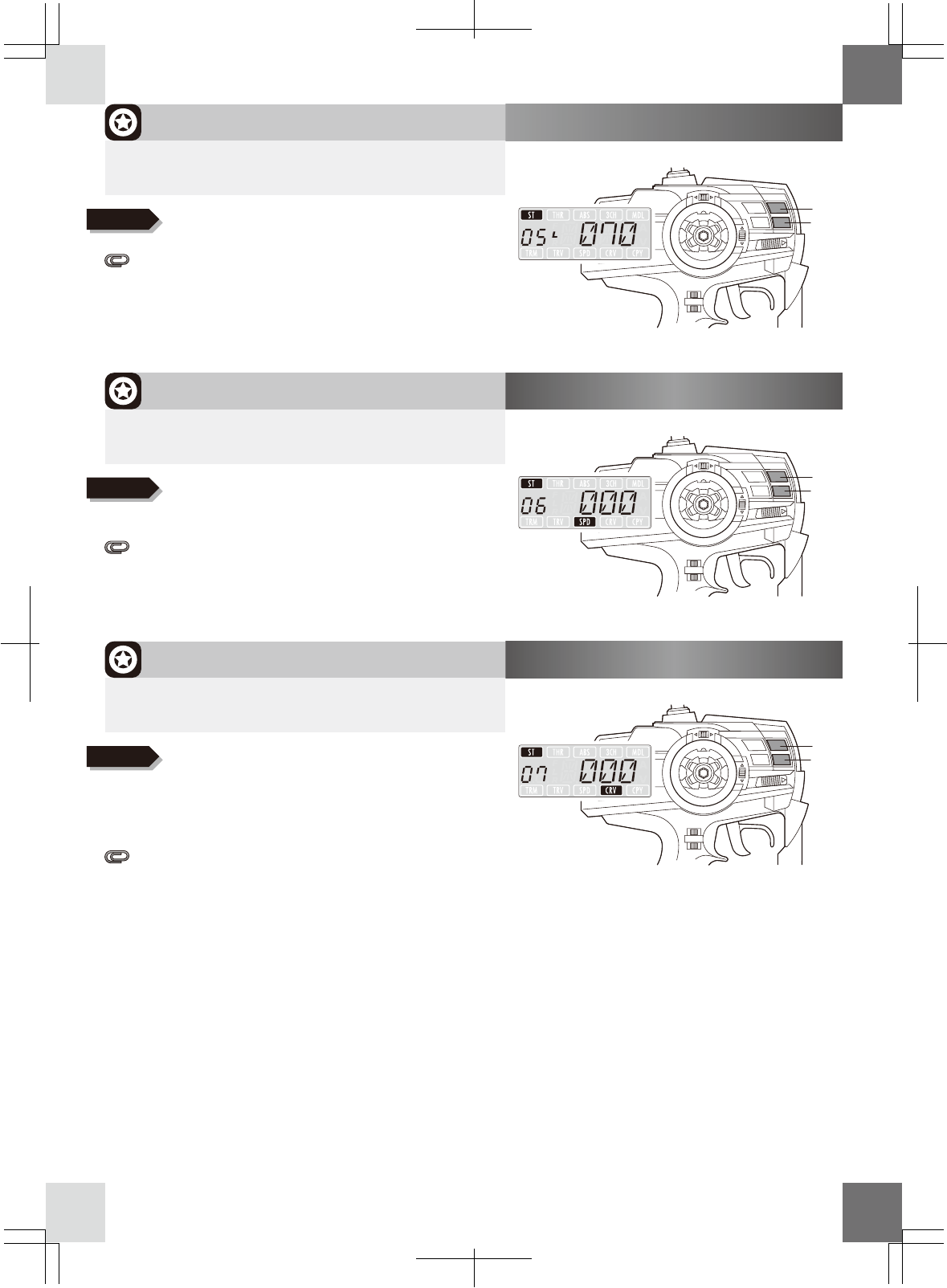
Whilst in braking operation, pumping brake prevents wheel lock and being unstable
(Anti Lock Braking System). Braking power and pumping speed can be adjusted.
① Adjust ABS power in "
MENU
19: ABS power". Increase values to expand pumping width.
② Adjust ABS speed in "
MENU
20 ABS speed".
③ If servo moves more than brake pad stroke range or vibrates due to excessive speed,
it may shorten life span of the servo. In this case, re-adjust.
Adjust the movement amount of speed controller (electric car) / throttle linkage (gas car)
▶When using with electric car: Refer to the instructions included with ESC.
▼When using with gas R/C car: Adjust throttle linkage
① Reduce values in “
MENU
12: Throttle high point” to avoid exerting excessive pressure on the
linkage when throttle is applied.
② Adjust in“
MENU
13: Throttle brake”to avoid exerting excessive pressure when brake is applied.
▶Adjusting throttle
▶Adjusting anti-lock brake (ABS)
■ Pairing/Steering/Throttle/ABS
※If left and right turning radius are not same at low speed running, increase values of steering balance
of smaller radius to adjust. Adjust steering travel to reduce turning angle if car turns excessively while
high-speed running.
※Frequent setting or worn-out linkage will deteriorate balance of steering. Periodical adjustment is
recommended to keep performance of steering.
7
6
▶Select using FORWARD/BACK button
※The transmitter automatically memorizes each setting 1
second after changing. When switching transmitter off, wait
more than 2 seconds after changing settings.
Functions (1-27)
Procedure when running
※EX-5UR automatically finds unused frequency band after switching on. This function is called "carrier sense". To
perform carrier sense effectively, switching on transmitter around the running area as close as possible.
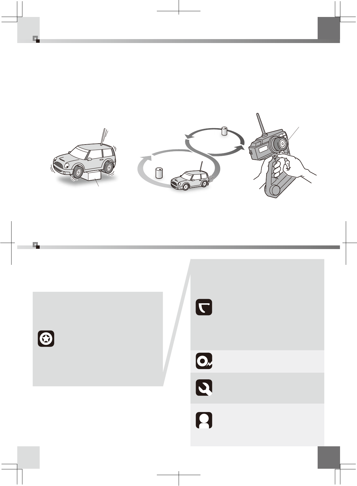
Checking model: Confirm model to be used.
2.
Power on: Note surroundings and switch transmitter on, then switch receiver on.
1.
Checking movements: Raise wheels from ground and operate transmitter to check
movements. Detail adjustment using steering/throttle trim lever should be done while
running. Adjust steering balance by operating 8-figure running.
3.
Power off: Switch off in receiver, transmitter order and remove running battery.
4.
※Make sure to switch transmitter on and off after an interval of 2 seconds at least.
■ Procedure when running/Functions (1-27)
MENU
08:Steering curve
‥‥‥‥
MENU
09:Steering reverse
‥‥‥
MENU
05:Steering balance L
‥‥
MENU
06:Steering speed
‥‥‥‥
MENU
07:Steering curve
‥‥‥‥
MENU
02:Steering trim‥‥‥‥‥
MENU
01:Steering monitor‥‥‥ P.7
P.7
P.7
P.7
P.8
P.8
P.8
P.9
P.9
MENU
04:Steering balance R
‥‥
MENU
03:Steering travel
‥‥‥‥
MENU
12:Throttle high point
‥‥
MENU
13:Throttle brake ‥‥‥‥
MENU
14:Throttle speed‥‥‥‥
MENU
11:Throttle trim
‥‥‥‥‥
MENU
10:Throttle monitor ‥‥‥
MENU
18:Throttle reverse
‥‥‥
MENU
17:Throttle sub trim‥‥‥
MENU
16:Throttle curve B ‥‥‥
MENU
15:Throttle curve F ‥‥‥
P.9
P.9
P.10
P.10
P.10
P.11
P.11
P.11
P.12
MENU
20:ABS speed‥‥‥‥‥‥
MENU
19:ABS power‥‥‥‥‥‥ P.12
P.12
MENU
21:3ch monitor ‥‥‥‥‥
MENU
23:Adjust volume ‥‥‥‥
MENU
22:3ch position setting
‥
P.13
P.13
P.13
MENU
24:Model reset ‥‥‥‥‥
MENU
25:Model copy ‥‥‥‥‥
MENU
26:Model name ‥‥‥‥‥
MENU
27:Model select‥‥‥‥‥
P.14
P.14
P.14
P.14
Stand
8-figure running
Trim lever
7
MENU
02:Steering trim
ET1 lever
※Max. width may be changed according to steering
travel/balance settings.
The position of the edge of movement does not move.
Only the neutral position moves.
When changing the edge of movement, adjust in
"
MENU
08:Steering sub trim".
Steering trim can also be adjusted by using ET1 lever.
L50 ∼ 0(Default setting) ∼ R50
▶
Neutral position of steering can be adjusted while running.
+/− keys. Push both keys together to reset.
Adjust using
+/− keys. Push both keys together to reset.
Adjust using
+/− keys. Push both keys together to reset.
Adjust using
MENU
01:Steering monitor Neutral position
▶Displays the current position of steering.
+ key
− key
Fully turns steering wheel to right and operate ET1 lever to
make setting of steering balance R.
MENU
04:Steering balance R
+ key
− key
40 ∼ 70(Default setting) ∼ 100
▶This function allows you to adjust right turning angle
(Use to correct left and right turning radius) ET1 lever
ET3 lever
Make sure the setting does not cause excessive force to
the servo as it may result in malfunction.
Steering travel can also be adjusted using ET3 lever.
When adjusting right and left movement individually, adjust in
"
MENU
04: Steering balance R" and "
MENU
05: Steering balance L".
MENU
03:Steering travel
+ key
− key
40 ∼ 100(Default setting)
▶This function allows you to adjust the amount of
servo movement when fully turns steering wheel.
■MENU 01∼04
If steering direction is changed in reverse position,
movement of steering and L/R will be reversed accordingly.
Caution!
Steering wheel
8
MENU
05:Steering balance L
+ key
− key
40 ∼ 70(Default setting) ∼ 100
▶This function allows you to adjust left turning angle.
(Use to correct left and right turning radius)
MENU
06:Steering speed
+ key
− key
100 ∼ 0(Default setting) ∼ +100
▶Use this function to adjust the steering speed
when turning steering wheel.
MENU
07:Steering curve
+ key
− key
50 ∼ 0(Default setting) ∼ +50
▶Use this function to adjust an initial response
of the steering servo.
■MENU 05∼07
Fully turns steering wheel to left and operate ET1 lever
to make setting of steering balance L.
※It effects on both TURN and RETURN directions.
Speed type servo may not move smoothly due to excessive
speed if sets over +30 values.
※+: Reacts greatly at the start, and the response becomes
loose later
−: Reacts loosely at the start, ant the response becomes
big later
When using with other function such as "steering speed",
check the effect one by one.
+/− keys. Push both keys together to reset.
Adjust using
+/− keys. Push both keys together to reset.
Adjust using
+/− keys. Push both keys together to reset.
Adjust using
9
ET2 lever
MENU
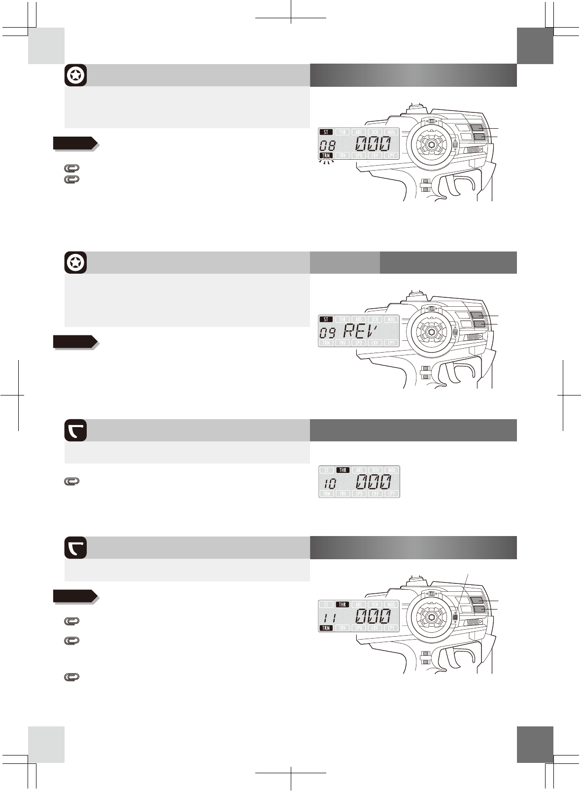
08:Steering sub trim
+ key
− key
L30 ∼ 0(Default setting) ∼ R30
▶This function allows you to adjust the edge of operation
and neutral position at the same time.
(Use when installing servo and test running)
MENU
11:Throttle trim
+ key
− key
b50 ∼ 0(Default setting) ∼ F50
MENU
09:Steering reverse
+ key
− key
NORM / REV(Default setting)
▶This function allows you to change the direction
of servo movement
(Use this function when the turning direction of servo
is opposite to the transmitter operation)
※REV:Reverse NORM:Normal
MENU
10:Throttle monitor Neutral position
▶Displays current throttle position.
▶Adjust neutral position of throttle while running
■MENU 08∼11
If throttle direction is in reverse position, +/− and throttle
movement will be reversed accordingly.
Adjust "
MENU
02: Steering trim" to adjust neutral position only.
When value of the sub trim gets bigger, adjust the linkage and
make it a smaller the value. In certain circumstances, too big
value may cause dead area (servo does not react) at the edge
of operation.
In general, trim adjustment is not required when using with
electric car with preset electronic speed controller (ESC).
The position of the edge of movement does not move. Only
the neutral position moves.
When changing the edge of movement, adjust in "
MENU
17:
Throttle sub trim".
Throttle trim can also be adjusted by using ET2 lever.
+/− keys. Push both keys together to reset.
Adjust using
+/− keys. Push both keys together to reset.
Adjust using
+/− keys. Push both keys together to reset.
Adjust using
10
MENU
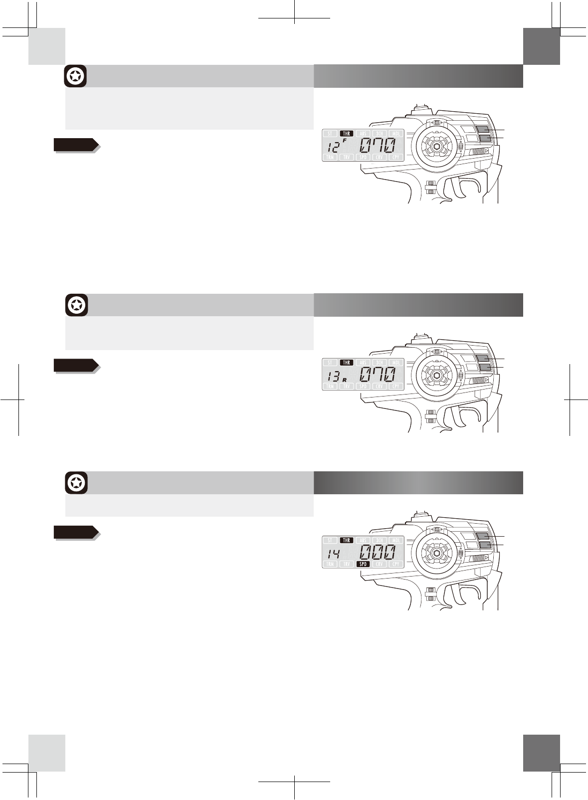
12:Throttle high point
+ key
− key
0 ∼ 70(Default setting) ∼ 100
▶Sets only the max forward movement on throttle.
(Allows you to adjust highest point of ESC of electric car
or“high”carburetor of gas car)
MENU
13:Throttle brake
+ key
− key
0 ∼ 70(Default setting) ∼ 100
▶Adjust only the brake of throttle and max movement
of reverse running.
MENU
14:Throttle speed
+ key
− key
100 ∼ 0(Default setting) ∼ +100
▶Adjust reaction velocity of throttle.
■MENU 12∼14
Creating a large value for a gas car puts an increase burden on
servo and may result in damage.
In an electric car, when set value is too small the ESC can not
show a better performance. Please start from +70 (factory
setting) setup.
Minimum value is 0 but doesn’t operate to forward. Also,
throttle servo does not move.
When a small the value of“Throttle high point” is made, and
then a large value in“
MENU
11: Throttle trim”is set to an advance
direction, the amount of operation will be extremely small.
+/− keys. Push both keys together to reset.
Adjust using
+/− keys. Push both keys together to reset.
Adjust using
+/− keys. Push both keys together to reset.
Adjust using
Caution!
Caution!
Caution!
Caution!
Caution!
Caution!
※To improve response, adjust in + direction.
※To improve handling, adjust in − direction
In an Electric car, a value set too small the ESC will not show
better performance. Please start from +70 (factory setting) in
this case.
Keep in mind that a brake or reverse running does not work
when a set up is 0. Please check the brake before running as
functions of ESC also effects on.
11
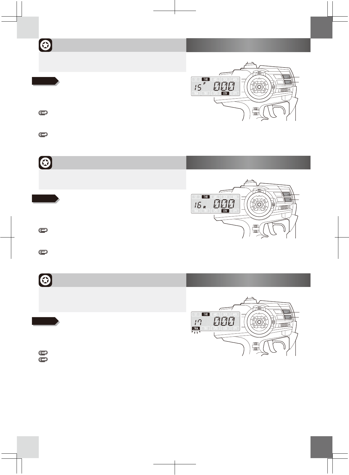
MENU
17:Throttle sub trim
+ key
− key
b30 ∼ 0(Default setting) ∼ F30
▶This function allows you to adjust the edge of operation
and neutral position at the same time.
(Use when installing servo and test running)
MENU
16:Throttle curve B
+ key
− key
50 ∼ 0(Default setting) ∼ +50
▶This function allows you to adjust throttle servo move-
ment on actual trigger operation (braking only).
MENU
15:Throttle curve F
+ key
− key
50 ∼ 0(Default setting) ∼ +50
▶This function allows you to adjust throttle servo move-
ment on actual trigger operation (forward only).
■MENU 15∼17
※The whole operation angle including neutral position moves.
Use this function if you can not corrects neutral position by
adjusting servo horn or linkage.
Adjust "
MENU
11: Throttle trim" to adjust neutral position only.
When value of the sub trim gets bigger, adjust the linkage and
make it a smaller the value. In certain circumstances, too big
value may cause dead area (servo does not react) at the edge
of operation.
※The throttle response can be made quick (+) or mild (−)
+ makes quick at start, and mild later
− makes mild at start, sensitive later
Quick curve (+ values) reacts greatly at the start, and the
response becomes mild later
Mild curve (− values) reacts mild at the start, ant the response
becomes sensitive later
When using with other function, check the effect one by one.
+/− keys. Push both keys together to reset.
Adjust using
+/− keys. Push both keys together to reset.
Adjust using
+/− keys. Push both keys together to reset.
Adjust using
12
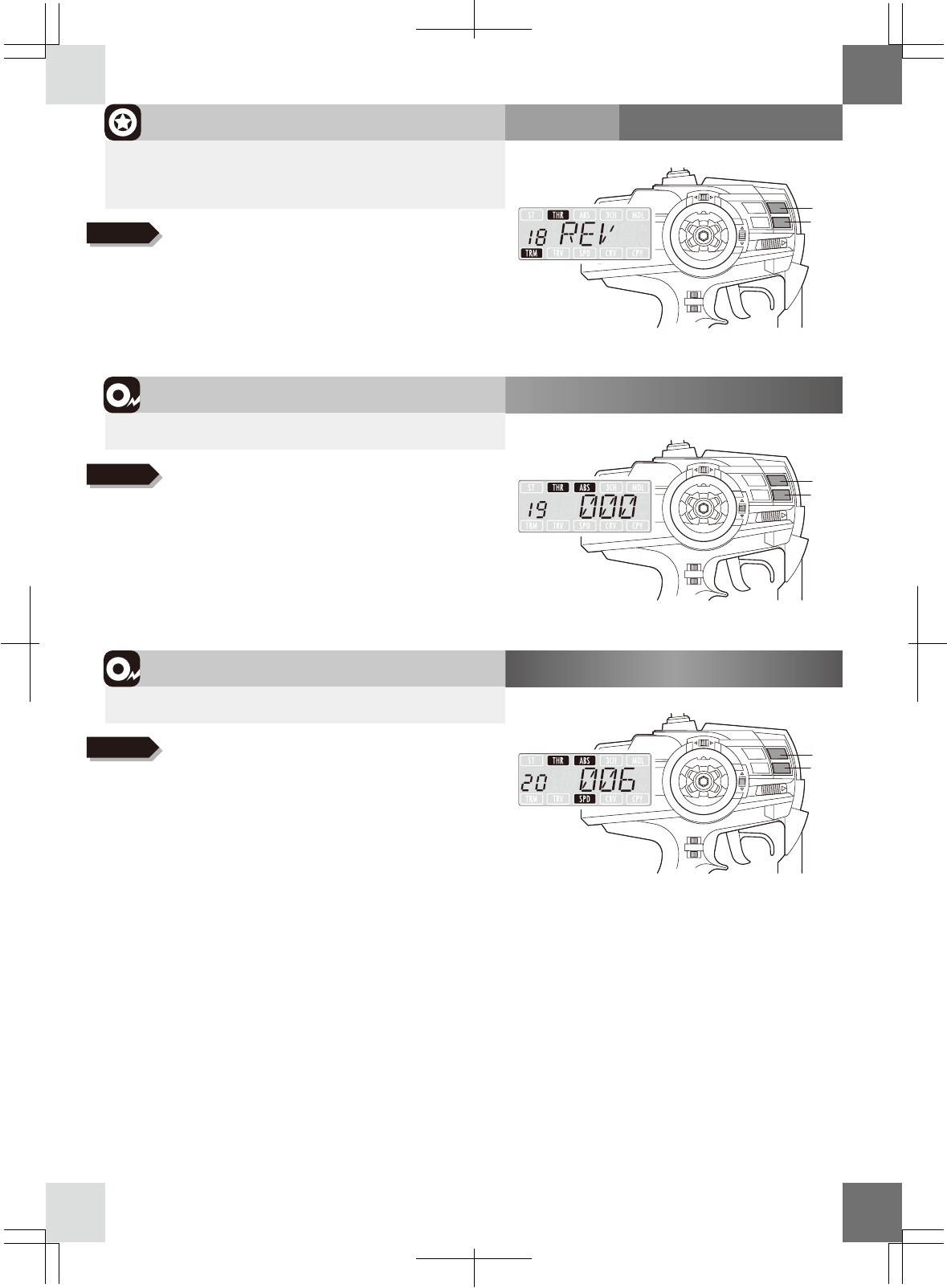
MENU
20:ABS speed
+ key
− key
1 ∼ 6(Default setting) ∼ 10
▶S
This function allows you to adjust speed of ABS
MENU
19:ABS power
+ key
− key
0(Default setting) ∼ 100
▶This function allows you to adjust amount of ABS pumping.
MENU
18:Throttle reverse
+ key
− key
NORM / REV(Default setting)
▶You can change the direction of throttle movement
(Use this function when the turning direction of servo
is opposite to the transmitter operation)
※REV:Reverse NORM:Normal
■MENU 18∼20
+/− keys. Push both keys together to reset.
Adjust using
+/− keys. Push both keys together to reset.
Adjust using
+/− keys. Push both keys together to reset.
Adjust using
Caution!
※Adjust pumping amount of ABS. Effective to improve stability
if wheel locks during braking and as a result cornering
becomes smoother.
※When making small the values, the servo moves slow
and pumping cycle become short.
When making large the values, the servo moves fast
and pumping cycle become long.
Too large values increase currency and may shorten life
span of servo.
13
Throttle trigger
MENU
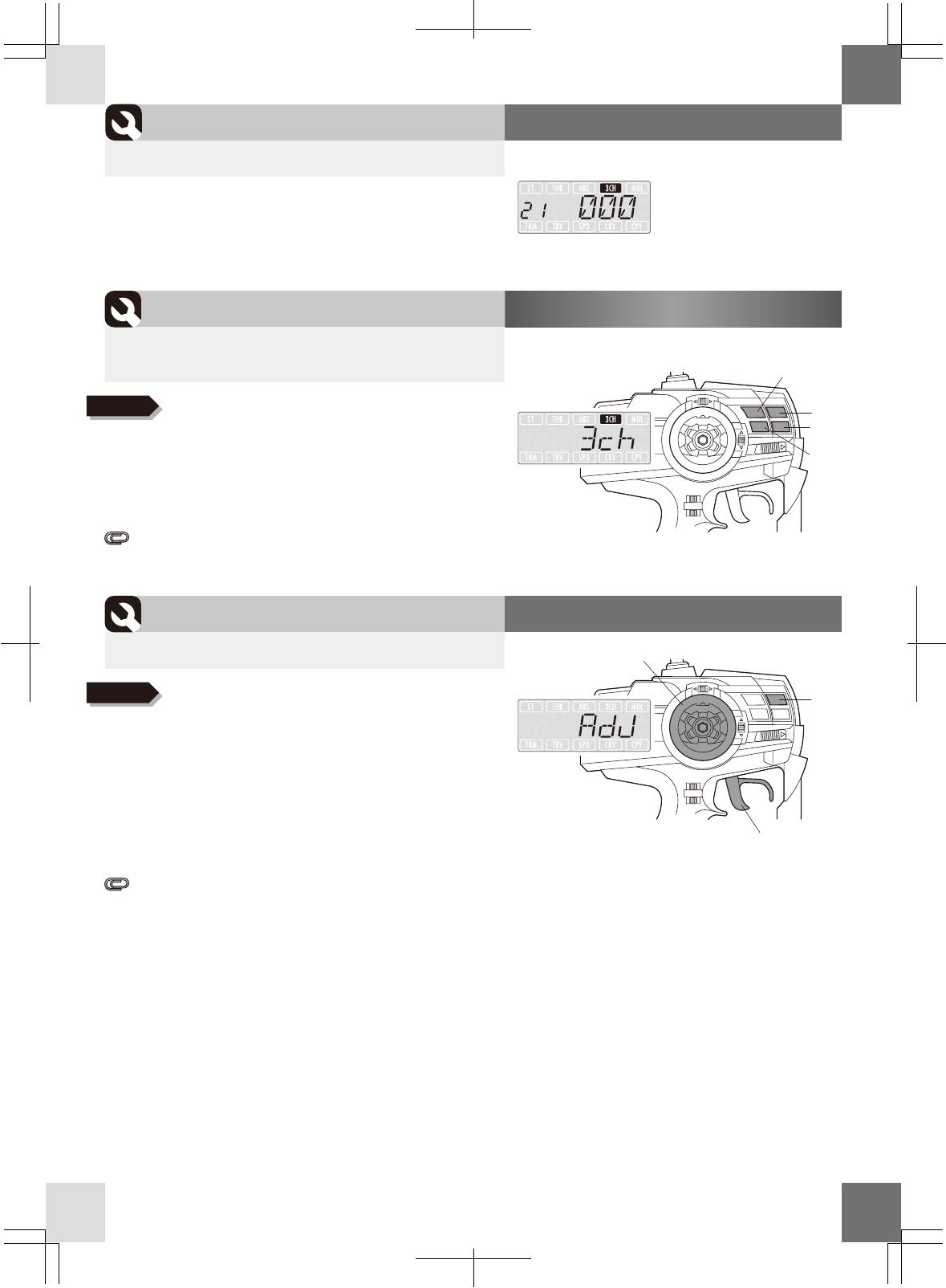
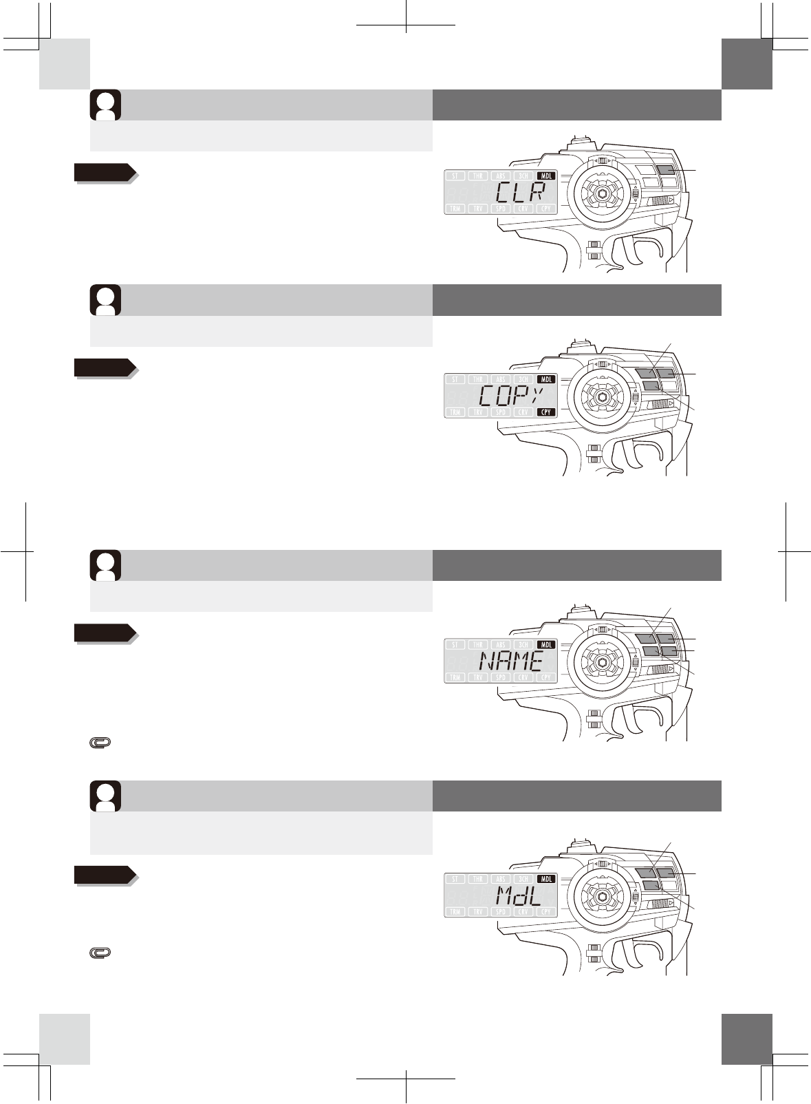
21:3ch monitor 3ch movement
Calibration
▶Displays current 3ch servo movement.
MENU
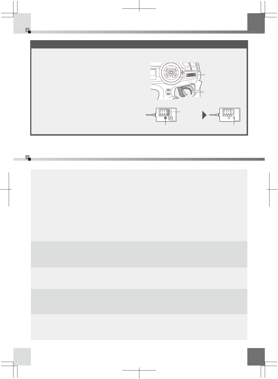
23:Adjust volume
+ key
▶Recalibrate used volume settings
MENU
22:
Adjustment of 3ch position
+ key
− key
127 ∼ (Each default positions) ∼ +127
▶Adjusting the movement amount of 3ch servo
in each position (position 01∼05)
■MENU 21∼23
Steering wheel
Foward key
Back key
※
CPU of the transmitter recognizes physical end points of
steering/throttle and neutral position. It corrects volume
consumption caused by frequently use or malfunction caused by shocks.
The use of this function will depend on your frequency of use and
your operation method
This function can cause trouble when it is performed incorrectly.
We recommend sending this to our service department for repair,
when you are not familiar with this function.
1. Hold + key for a while
2. Use Forward/Back keys to choose positions
3. Push +/- keys to set positions.
Push both keys together to reset.
4. Push Forward key from (05 position) then
LCD displays "EXIT". Push + key to set.
Adjust using
1. Hold + key for a while
2. Fully turn steering wheel to right/left
then release.
3. Fully pull/press throttle trigger in
forward/reverse position then release.
4. LCD displays“OK”. Then, hold + key
for a while to set.
Adjust using
Caution!
5 positions (-100 / -50 / 0 / +50 / +100 ) are factory preset.
14
All usable letters: −*/@_ ̄¥\0123456789
AbCdEFGHIJKLMNOPQRSTUVWXYZ +
MENU
24:Model reset
+ key
▶This will erase all data of model memory.
MENU
25:Model copy
+ key
▶Save the current model memory to other model memory
MENU
26:Model name
+ key
− key
▶Putting a name in the model memory.
MENU
27:Model select
+ key
▶You can change current model memory to other
model memory.
Reset
Copy
Registration
Select
■MENU 24∼27
Foward key
Back key
Foward key
Back key
Foward key
Back key
1. Push + key.
2. Push +/− keys to select alphabets
and numbers.
3. Push Forward/Back keys to select letters.
4. Push Forward key after selecting 4th letter.
Push + key after LCD displaying“EXIT”.
Adjust using
1. Push + key.
2. Use Forward/Back keys to choose
a copy place (model number).
3. Push + key to copy.
Adjust using
Hold + key for a while to erase
Adjust using
1. Push + key
2. Push Forward/Back keys to choose
other model memory.
3. Push + key to set.
Adjust using
Caution!
Caution!
Caution!
Caution!
※LCD turns off when setting is finished.
Memory will be reset back to the factory settings.
※Copying data of model memory is useful when adjusting
chassis setting according to condition of the track.
Please be sure that copy destination data will be overwritten.
The mode will be moved to “model select” of copy destination.
If copying model 1 to model 2, model select will be changed to
model 2 and data of model 1 (original data) will be saved.
You can save the model memory for 7 cars. It is useful to save each
model memory to use several cars. Even the same car can have
multiple numbers due to changes to the settings at every course.
Can cause of out of control operation when changing model
memory while running.
15
●Model does not work though the transmitter is on
LCD display is displayed with the start sound after switching on. If not, check batteries .
If there is no problem with transmitter, check LED indicator of the receiver.
① In case of the LED is too dark or blinking, it shows conflicting radio signals from other
sources. Change location or take some time before switching on.
②Power is not on if the LED does not shine. Reconnect receiver battery or amplifier cables.
●To increase cornering angle
If steering angle is not enough, adjust steering travel lever to increase travel.
Use“
MENU
04/05: steering balance”to get more angle.
●To improve steering response
Adjust“
MENU
07: steering curve”or“
MENU
06: steering speed”at +(quick) side.
●To make steering characteristics milder
Adjust“
MENU
07: Steering curve”or“
MENU
06: Steering speed”at −(mild) side.
Adjust“
MENU
07: Throttle speed at -side.
●To slow down
Adjust“
MENU
14: Throttle speed”at −side.
Adjust“
MENU
12: Throttle high point”at −side.
Safety function
References
■ Safety function/References
Failsafe automatically returns throttle (2ch) in desired position (full brake/neutral) if the model may run out
of control.
① Switch transmitter on.
② Switch receiver on and check servo movement.
③ Operate throttle trigger in brake/neutral position
(transmitter memorizes the position)
④ Hold set button of receiver more than 3 seconds.
Release after LED turns off.
▶Failsafe setting
1. Power
3. Throttle trigger
(full brake/neutral)
2. Power
4. Set button (hold 3 seconds) 5. LED (off)
EX-5UR(transmitter) uses 2,4GHz direct sequence spread spectrum (DS-SS) as a frequency
band. The frequency band is also used for electric appliances such as personal computer
w/wireless LAN, Bluetooth and microwave oven. In the case of radio interference, LED of
KR-407(receiver) will not turns on correctly. Wait for a while or change location if LED flashes or
lit up incorrectly.
※Failsafe function can be checked by switching
off transmitter. The data will be memorized until
resetting.
※When replacing brake linkage of a gas car,
resetting is recommended.
Caution!
16
After-sales service
■ Spec/After-sales service
Transmitter: KT-309
Operation method: Wheel + trigger type
Number of channels: 3 channels
Frequency: 2.4GHz
Modulation: Direct sequence spread spectrum
(DS-SS)
Output: Approx. 10mW
Neutral pulse: 1.5msec
Data save memory: EEPROM
Supply voltage: R6/AA/UM3 size battery x 8 or 8
cells battery pack
Current consumption: Approx. 100mAh
Operation area: Approx. within 80m radius
Function: Compatible with High Speed Response
(ULTRA)
Receiver: KR-407S
Modulation: Direct sequence spread spectrum
(DS-SS)
Channels: 4 channels
Dimensions: 28×18.3×18.5mm
Weight: 7.4g
Supply voltage: 4.8∼7.4VFunction: Compatible with
High Speed Response (ULTRA or above), ICS,
Failsafe