Kondo Kagaku T090825 RC transmitter for car model User Manual UserMan
Kondo Kagaku Co., Ltd. RC transmitter for car model UserMan
UserManual.wiki
>
Kondo Kagaku
>
T090825 User Manual
UserMan
Navigation menu
Upload a User Manual
Namespaces
Wiki Guide
HTML
PDF
Info
Views
User Manual
Discussion / Help
Navigation
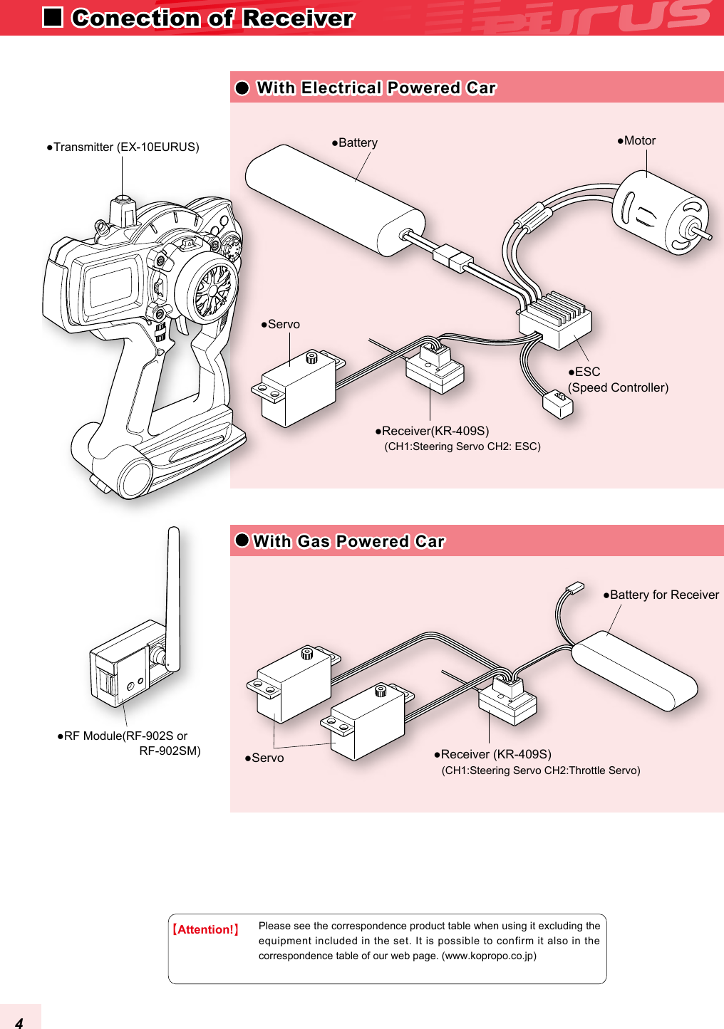
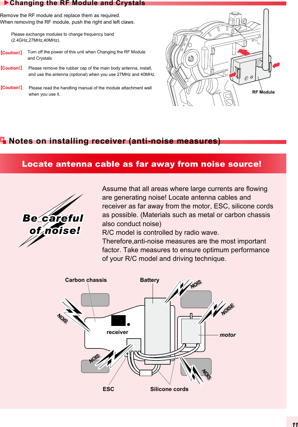
![Throttle triggerPOWER SwitchBACK KeyPower indicatorENTEREnter KeyET3 LeverJOG DIAL(+)Plus keyLM2 LEDindicator2 LM3 LEDindicator3LM1 LEDindicator1ET4 LeverET5 LeverBT1Push Switch[Factory Setting]ET1:Steering TrimET2:Throttle TrimET3:Throttle BrakeET4:SteeringET5:CH3 controlBT1:Not AssignedBT2:Not AssignedHook ET1LeverSteering Wheel12x4 LCD DisplayET2LeverBT2(-)Minus key[Usage]Each direction doesn't turn on constancy. So when it becomes tight, do not turn the tension any more. The tension adjustment can be adjusted by the hole above the ET4 button (figure right) with a hex-head wrench of 1.5mm.The tension strengthens when turning in the clockwise direction. It weakens when turning in the opposite direction.Strength of the spring of the steering wheel can be adjusted.�Adjustment of Steering TensionBattery Box(inside)A hex-head wrench of 1.5mm.7 NAME OF PARTSTransmitter(Front View)](https://usermanual.wiki/Kondo-Kagaku/T090825/User-Guide-1245722-Page-5.png)
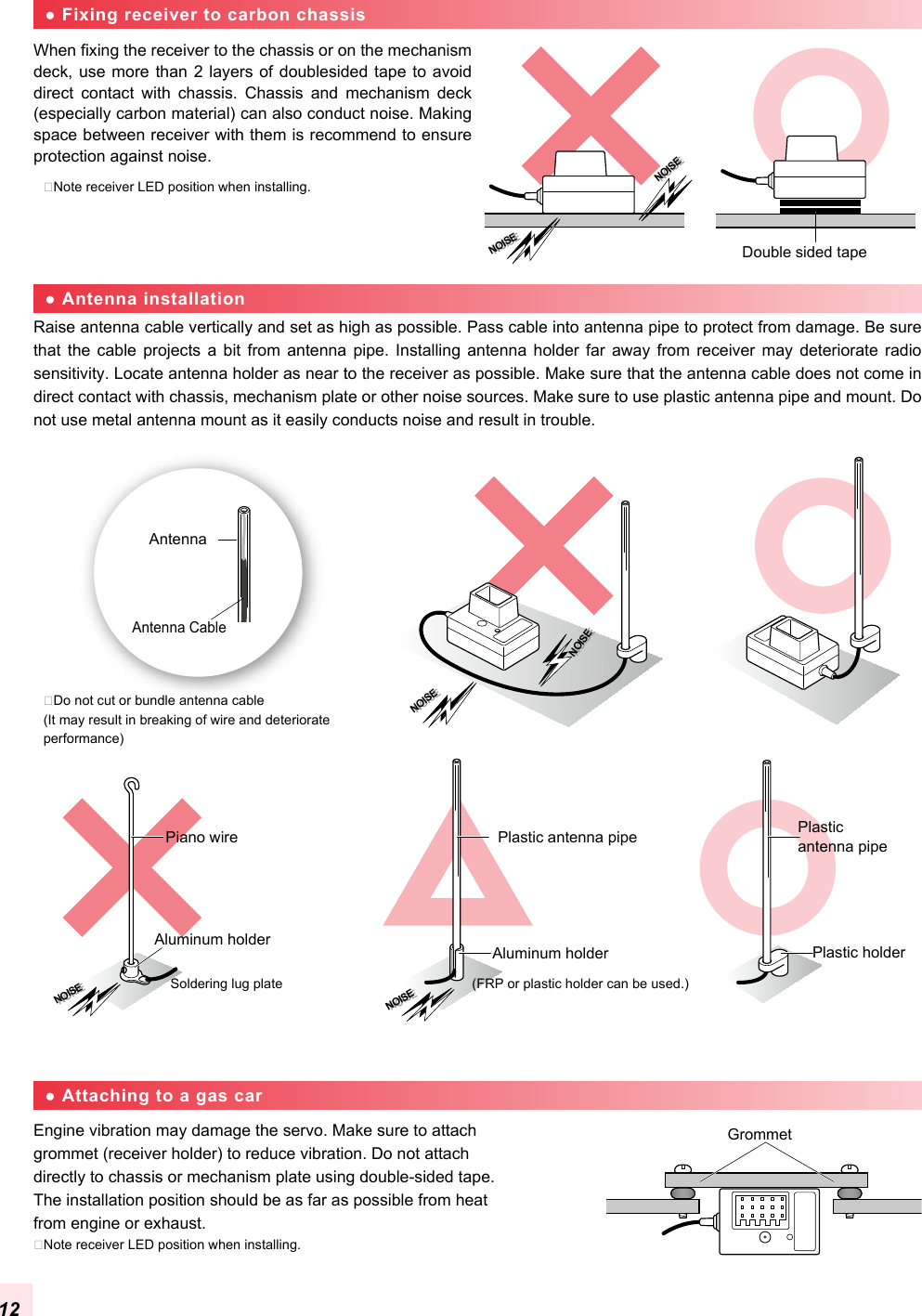
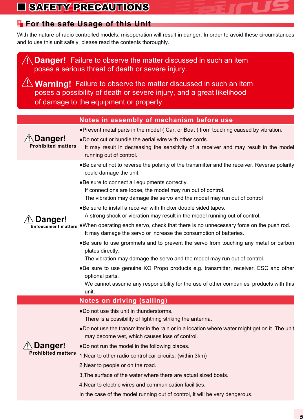
![Phone Terminal(Refer P.8)D.S.C.(Direct Servo Control)Terninal.(Refer P.8)MultiAccessPort(Refer P.8)CHARGING(Refer P.10)RF Module(Refer P.11)Battery Channel[Receivers]Turn off the power switch of the transmitter and connect the DSC cable to the DSC terminal.The power supply of the transmitter enters when the DSC cable is connected.Connect Servo and check it.5. Connect Battery to the receiver.4. (Case of KR-409S Usage) Please change mode to “Digital”.(Case of Older Receiver Usage) Please change to NORMAL,HighSPD,or ADVANCE.2. Once you are finished using DSC, turn off the receiver side first then DSC Jack should pulled out.6. The other side of the DSC cable is connected to the receiver. 3. 1. The crystal of the receiver is pulled out.[Coution!]Because the DSC function is installed in this unit, the setting can be confirmed without putting out the electric wave. A D.S.C. cable (optional) is necessary to use this function.Receivers that will work with this function should be a KO Propo genuine product which is compatible with DSC.The buzzer sound can be clearly confirmed by using the earphone jack. Commercially available Φ3.5earphone for radios can be used. (MONO type can be used. With STEREO type, only one side will be heard.)This is useful when you cannot hear the buzzer sound due to other outside noises. The Buzzer sound can be heard from the transmitter even when the earphone jack is connected.The 10 model memory in the main unit can have an additional 40 model memory.The multi access port offers a new method of installing, exchanging and the editing of new settings information.Obtaining the Data Pack and the communications adaptor can be used for the multi access port. [Data Pack (optional)]The two way communication is possible by connecting the PC to your transmitter with the optional interface kit. By using the software from the interface kit, settings of the transmitter can be edited in PC and the data can be saved regardless of the number of model memory.D.S.C.TerminalMultiAccessPortPhone Terminal[I.C.S Communication Adaptor(optional)+I.C.S USB Adaptor(optional)]8Transmitter(backside view)](https://usermanual.wiki/Kondo-Kagaku/T090825/User-Guide-1245722-Page-6.png)
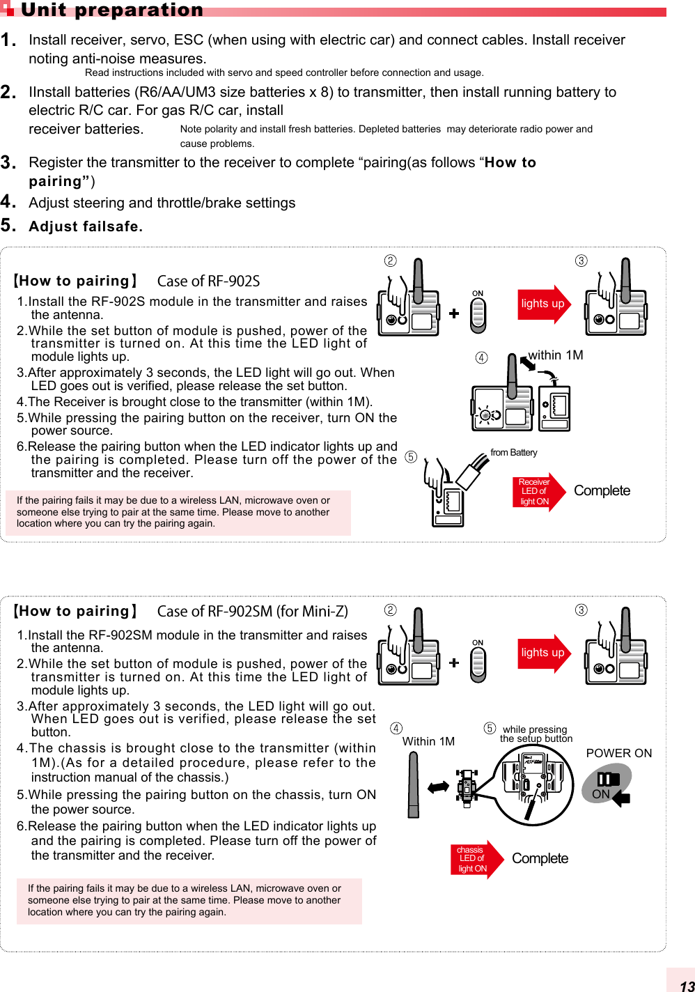
![PadGripAdjusting the steering angle�To return to the initial state, adjust the hexagon socket head screw so that the tip does not protrude from the tapped hole by a small distance.�Please refer to the manual of the attached paper for the installation of the unit. The installation angle of the steering wheel foil can be freely adjusted. [Procedure]1. Remove the sponge from the steering wheel.2. Insert the hexagonal socket wrench (2 mm) into the two holes of steering wheel and tighten the hexagon socket head screws.3. Attach the sponge to the steering wheel.4. Referring to page 45, set "#ADJVOL" (adjust variable resistor).[Procedure]1. A Hexagon socket head screw of the throttle lever is loosened by Hexagon socket wrench.2. The brake lever is adjusted to an arbitrary position.3. A Hexagon socket head screw is tightened, and fixed. 3D Adjustable triggerWheel Extention UnitThe position of the brake lever and the adjustment of the angle can be freely done. It is possible to exchange it for other color pad and grip. Setting of Wheel and triggerColor Pad and Replace Grip(optional)Hexagon socketwrench (2 mm)Steering wheelDecrement anglespacerHexagon sockethead screwHexagon sockethead screw(1.5mm)Hexagon sockethead screwBall JointBrake lever[Throttle Lever][Steering unit][Wheel inside][How to remove pad or grip.]Pull in the direction of the arrow (3), the pad removes using your fingernail (4).After expanding the lower side (1), the whole grip pulls the in direction (2) of the arrow.[How to attach pad or grip.]Do this in the reverse order of the removal procedure. The lower side of the pad is slid in. Then using your fingernail the upper side (3) of the pad is inserted into the transmittor case.Slide the grip onto the case and then push the six tabs into the case using your fingernails. If it is not easy to insert the tabs into the case, push them in by using a minus driver etc. Do not using anything that will damage the case. Finally, push the guide pins that exists in the lower side (2) into the case.[Procedure]1. Two Hexagon socket head screws under the wheel extension are loosened by Hexagon socket wrench (3 mm).2. The position is adjusted at the position of the favor.3. Hexagon socket head screw is tightened, and fixed. 9](https://usermanual.wiki/Kondo-Kagaku/T090825/User-Guide-1245722-Page-7.png)
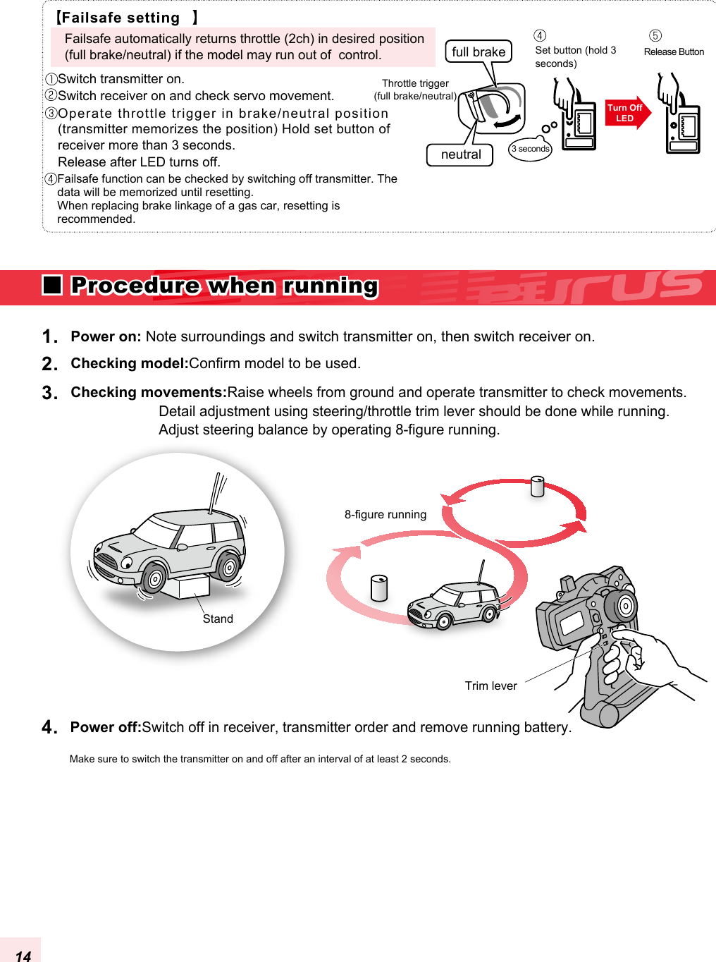
![Battery pack (option)Do not use AA size Ni-cd or NiMH batteries. The inside of the transmitter corrodes by generating gases when charging it.Transmitter(bottom)(1)The direction is matched to the display of the plus or minus of the dry battery box, and eight AA size batteries are put. (2)The direction of the terminal of the dry battery box and the terminal of the transmitter is matched and it pushes it into the interior. (3)The battery cover is closed.2. Please attach included sponge to the battery lid when the battery pack is used.(1)The connector is inserted noting the direction as shown in figure. (2)Insert battery pack and close the cover.(3)Be careful not to trap the cord.Rechargeable Ni-MH battery pack.The charging time from flat condition is 14-16 hrs for AC Mains charger.Connect AC Mains charger as shown in figure.Pressing in the direction of the arrow of(1). while pushing the part in the arrow of (2).1. Battery CoverBattery BoxContactCharger Battery PackAA size batteries8pcsCoution!Do not charge when dry cell batteries are used.Coution!Note!Coution!Coution!If the charge plug is inserted, the power supply of the transmitter is turned off. How To Insert Batteries[How To Insert Batteries][About Charging (only for battery packs)]Be careful to the polarity of the connector Not in useBe careful to the polarity of the connector.Do not use it excluding the battery made of our company. 10 PREPARATION FOR USING THIS UNIT](https://usermanual.wiki/Kondo-Kagaku/T090825/User-Guide-1245722-Page-8.png)