Kondo Kagaku T090826 RC transmitter for car model User Manual UserMan
Kondo Kagaku Co., Ltd. RC transmitter for car model UserMan
UserMan

Instruction Manual
With Gas Powered Car With Gas Powered Car
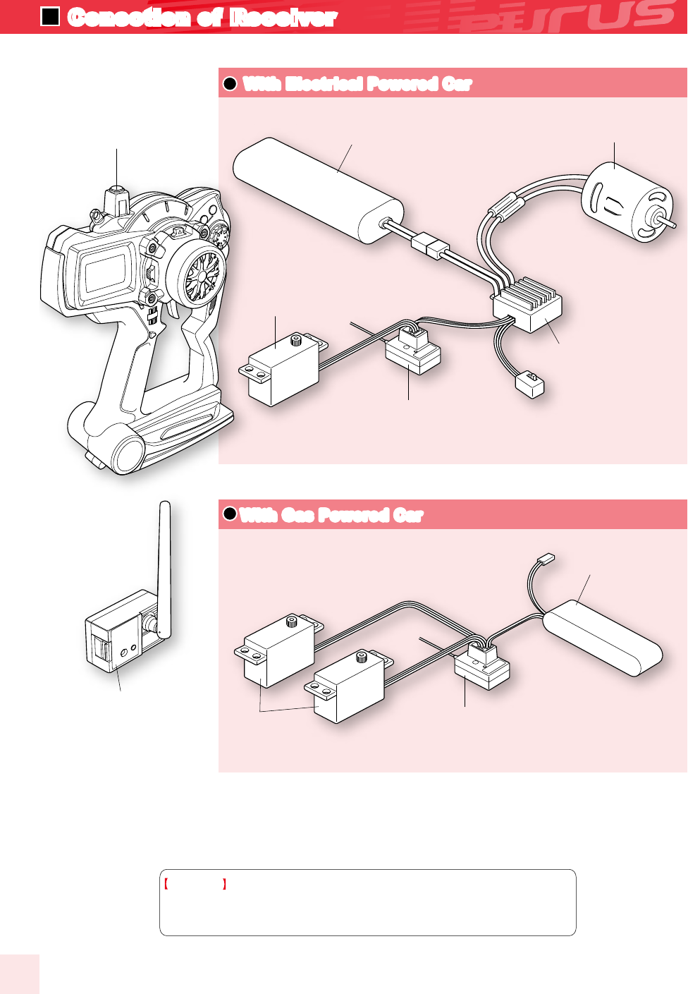
With Electrical Powered Car
With Electrical Powered Car
●Battery
●Receiver (KR-409S)
●Motor
●ESC
(Speed Controller)
●Battery for Receiver
●Servo
●Servo
●Transmitter (EX-10EURUS)
●RF Module(RF-902S or
RF-902SM)
●Receiver(KR-409S)
Please see the correspondence product table when using it excluding the
equipment included in the set. It is possible to confirm it also in the
correspondence table of our web page. (www.kopropo.co.jp)
Attention!
(CH1:Steering Servo CH2: ESC)
(CH1:Steering Servo CH2:Throttle Servo)
4
Conection of Receiver
With the nature of radio controlled models, misoperation will result in danger. In order to avoid these circumstances
and to use this unit safely, please read the contents thoroughly.
●Prevent metal parts in the model ( Car, or Boat ) from touching caused by vibration.
●Do not cut or bundle the aerial wire with other cords.
It may result in decreasing the sensitivity of a receiver and may result in the model
running out of control.
●Be careful not to reverse the polarity of the transmitter and the receiver. Reverse polarity
could damage the unit.
●Be sure to connect all equipments correctly.
If connections are loose, the model may run out of control.
The vibration may damage the servo and the model may run out of control
●Be sure to install a receiver with thicker double sided tapes.
A strong shock or vibration may result in the model running out of control.
●When operating each servo, check that there is no unnecessary force on the push rod.
It may damage the servo or increase the consumption of batteries.
●Be sure to use grommets and to prevent the servo from touching any metal or carbon
plates directly.
The vibration may damage the servo and the model may run out of control.
●Be sure to use genuine KO Propo products e.g. transmitter, receiver, ESC and other
optional parts.
We cannot assume any responsibility for the use of other companies’ products with this
unit.
●Do not use this unit in thunderstorms.
There is a possibility of lightning striking the antenna.
●Do not use the transmitter in the rain or in a location where water might get on it. The unit
may become wet, which causes loss of control.
●Do not run the model in the following places.
1,Near to other radio control car circuits. (within 3km)
2,Near to people or on the road.
3,The surface of the water where there are actual sized boats.
4,Near to electric wires and communication facilities.
In the case of the model running out of control, it will be very dengerous.
Danger! Failure to observe the matter discussed in such an item
poses a serious threat of death or severe injury.
Notes in assembly of mechanism before use
Notes on driving (sailing)
Danger!
Prohibited matters
Danger!
Enfoecement matters
Danger!
Prohibited matters
For the safe Usage of this Unit
Warning! Failure to observe the matter discussed in such an item
poses a possibility of death or severe injury, and a great likelihood
of damage to the equipment or property.
5
SAFETY PRECAUTIONS

●Do not allow any plastic parts to come in contact with fuel and exhaust.
Doing so causes risk of damage.
●Be sure to confirm that the model memory is matched to the models currently running.
Not doing so may cause the model to run out of control.
●When you make functional changes, be sure to stop the engine or disconnect the motor
lead wire.
●Do not touch the engine, motor, ESC where heat is generated.
May result in burning.
●Always turn on the switch on the transmitter first, followed by the receiver. When turning
off the switch, always turn off the receiver first, followed by the transmitter.
If you don’t follow the correct order, the receiver may get interference.
●Altering the transmission module is inhibited by law and is subjected to penal code
violations. Resolution remodelling of all products may result in the cause of a short and
other accidents. In addition, if this product is altered we will refuse repair service.
●Please do not use this product inside an airplane, hospital, near any automatic control
equipment, medical electrical machinery and apparatus such as fire alarms.
In addition with respect to the law, if this product effects other radio equipment and
electronic equipment, use must be discontinued at once.
●In the case of an electric-powered car, be sure to disconnect the nicad battery afterwards.
It may cause fire or the model to run out of control in case of the switch being left on.
●When storing the transmitter, batteries, and models, be sure to keep them out of the
reach of children.
It may result in damage and/or bodily injury from the chemicals.
●Be sure to disconnect the battery from the transmitter when not in use for a long time.
It may damage the transmitter if you leave the battery in the transmitter for a long time.
●Do not store the transmitter in the following places.
1,Extremely hot or cold places (+40, -10,).
2,Direct sunshine.
3,Places with high humidity.
4,Dusty places.
If you store the unit under these circumstances, it may result in misoperation or damage
to the unit.
Notes After Driving (sailing)
Danger!
Prohibited matters
Danger!
Prohibited matters
Danger!
Enfoecement matters
Danger!
Enfoecement matters
Danger!
Enfoecement matters
Danger!
Enfoecement matters
6
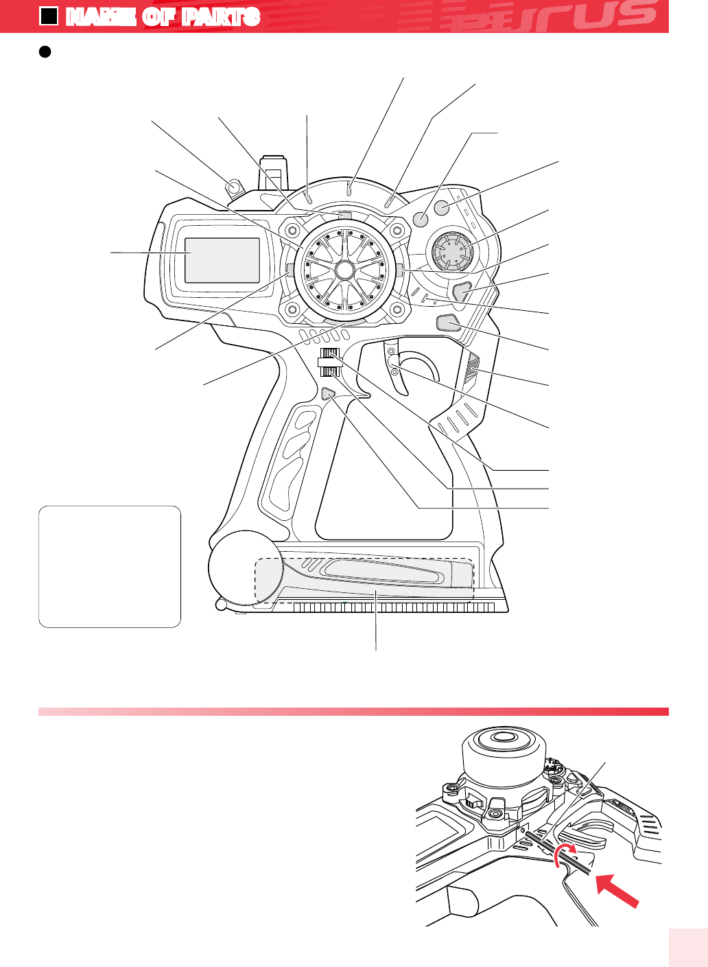
Throttle trigger
POWER Switch
BACK Key
Power indicator
ENTER
Enter Key
ET3 Lever
JOG DIAL
(+)Plus key
LM2 LED
indicator2 LM3 LED
indicator3
LM1 LED
indicator1
ET4 Lever
ET5 Lever
BT1
Push Switch
[Factory Setting]
ET1:Steering Trim
ET2:Throttle Trim
ET3:Throttle Brake
ET4:Steering
ET5:CH3 control
BT1:Not Assigned
BT2:Not Assigned
Hook ET1Lever
Steering Wheel
12x4
LCD Display
ET2Lever
BT2
(-)Minus key
[Usage]
Each direction doesn't turn on constancy. So when it becomes tight, do
not turn the tension any more. The tension adjustment can be adjusted
by the hole above the ET4 button (figure right) with a hex-head wrench of
1.5mm.
The tension strengthens when turning in the clockwise direction. It
weakens when turning in the opposite direction.
Strength of the spring of the steering wheel can be adjusted.
�Adjustment of Steering Tension
Battery Box(inside)
A hex-head wrench
of 1.5mm.
7
NAME OF PARTS
Transmitter(Front View)
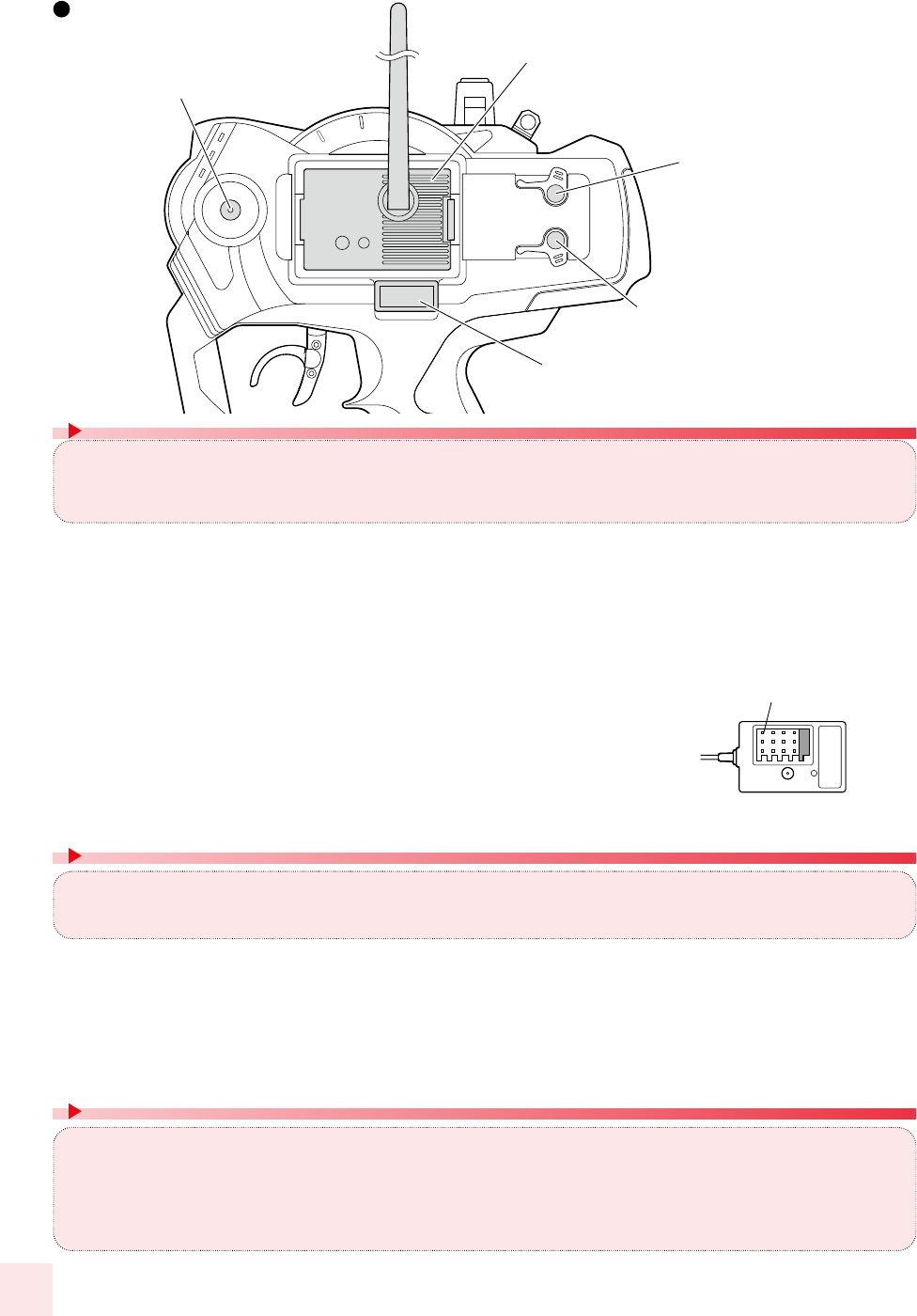
Phone Terminal
(Refer P.8)
D.S.C.(Direct Servo Control)
Terninal.(Refer P.8)
MultiAccessPort
(Refer P.8)
CHARGING
(Refer P.10)
RF Module
(Refer P.11)
Battery Channel
[Receivers]
Turn off the power switch of the transmitter and connect the DSC cable to the DSC terminal.
The power supply of the transmitter enters when the DSC cable is connected.
Connect Servo and check it.
5.
Connect Battery to the receiver.
4.
(Case of KR-409S Usage) Please change mode to “Digital”.
(Case of Older Receiver Usage) Please change to NORMAL,HighSPD,or ADVANCE.
2.
Once you are finished using DSC, turn off the receiver side first then DSC Jack should pulled out.
6.
The other side of the DSC cable is connected to the receiver.
3.
1.
The crystal of the receiver is pulled out.
[Coution!]
Because the DSC function is installed in this unit, the setting can be confirmed without putting out the electric wave. A D.S.C.
cable (optional) is necessary to use this function.
Receivers that will work with this function should be a KO Propo genuine product which is compatible with DSC.
The buzzer sound can be clearly confirmed by using the earphone jack. Commercially available Φ3.5earphone for radios can
be used. (MONO type can be used. With STEREO type, only one side will be heard.)
This is useful when you cannot hear the buzzer sound due to other outside noises. The Buzzer sound can be heard from the
transmitter even when the earphone jack is connected.
The 10 model memory in the main unit can have an additional 40 model
memory.
The multi access port offers a new method of installing, exchanging and the editing of new settings information.Obtaining the
Data Pack and the communications adaptor can be used for the multi access port.
[Data Pack (optional)]
The two way communication is possible by connecting the PC to your transmitter with the optional interface kit. By
using the software from the interface kit, settings of the transmitter can be edited in PC and the data can be saved
regardless of the number of model memory.
D.S.C.Terminal
MultiAccessPort
Phone Terminal
[I.C.S Communication Adaptor(optional)+I.C.S USB Adaptor(optional)]
8
Transmitter(backside view)
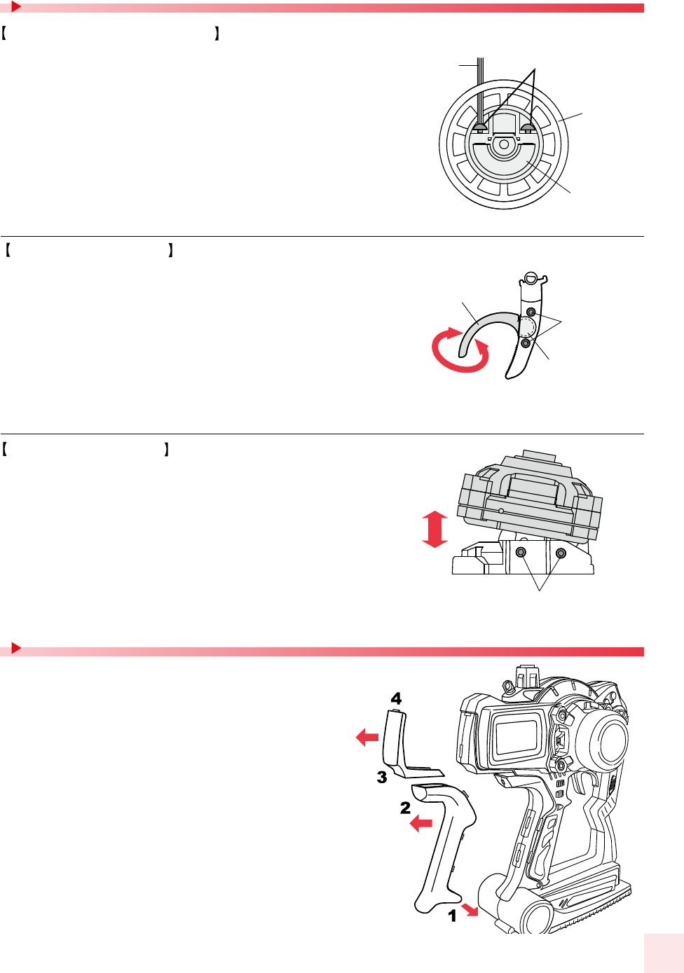
Pad
Grip
Adjusting the steering angle
�To return to the initial state, adjust the hexagon socket head screw so that the tip
does not protrude from the tapped hole by a small distance.
�Please refer to the manual of the attached paper for the installation of the unit.
The installation angle of the steering wheel foil can be freely
adjusted.
[Procedure]
1. Remove the sponge from the steering wheel.
2. Insert the hexagonal socket wrench (2 mm) into the two holes of steering
wheel and tighten the hexagon socket head screws.
3. Attach the sponge to the steering wheel.
4. Referring to page 45, set "#ADJVOL" (adjust variable resistor).
[Procedure]
1. A Hexagon socket head screw of the throttle lever is loosened by Hexagon
socket wrench.
2. The brake lever is adjusted to an arbitrary position.
3. A Hexagon socket head screw is tightened, and fixed.
3D Adjustable trigger
Wheel Extention Unit
The position of the brake lever and the adjustment of the angle can be
freely done.
It is possible to exchange it for other color pad and grip.
Setting of Wheel and trigger
Color Pad and Replace Grip(optional)
Hexagon socket
wrench (2 mm)
Steering wheel
Decrement angle
spacer
Hexagon
socket
head screw
Hexagon
socket
head screw
(1.5mm)
Hexagon
socket
head screw
Ball Joint
Brake lever
[Throttle Lever]
[Steering unit]
[Wheel inside]
[How to remove pad or grip.]
Pull in the direction of the arrow (3), the pad removes using your
fingernail (4).
After expanding the lower side (1), the whole grip pulls the in direction
(2) of the arrow.
[How to attach pad or grip.]
Do this in the reverse order of the removal procedure. The lower side of the
pad is slid in. Then using your fingernail the upper side (3) of the pad is
inserted into the transmittor case.
Slide the grip onto the case and then push the six tabs into the case using
your fingernails. If it is not easy to insert the tabs into the case, push them in
by using a minus driver etc. Do not using anything that will damage the case.
Finally, push the guide pins that exists in the lower side (2) into the case.
[Procedure]
1. Two Hexagon socket head screws under the wheel extension are
loosened by Hexagon socket wrench (3 mm).
2. The position is adjusted at the position of the favor.
3. Hexagon socket head screw is tightened, and fixed.
9
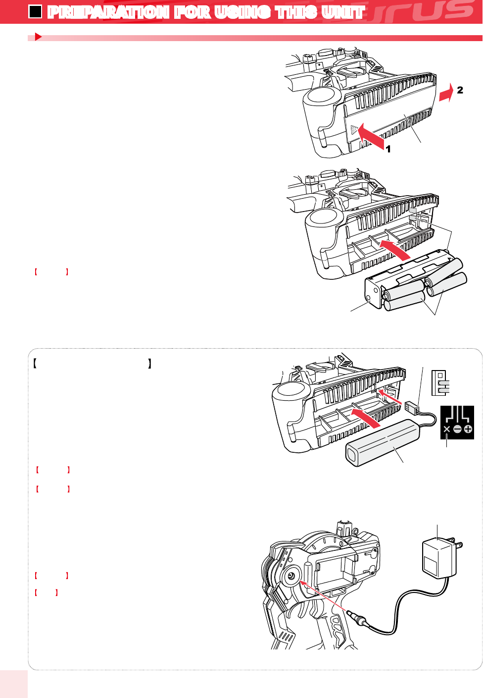
Battery pack (option)
Do not use AA size Ni-cd or NiMH batteries.
The inside of the transmitter corrodes by generating gases
when charging it.
Transmitter(bottom)
(1)The direction is matched to the display of the plus or minus of
the dry battery box, and eight AA size batteries are put.
(2)The direction of the terminal of the dry battery box and the
terminal of the transmitter is matched and it pushes it into the
interior.
(3)The battery cover is closed.
2.
Please attach included sponge to the battery lid when the battery pack is
used.
(1)The connector is inserted noting the direction as shown in
figure.
(2)Insert battery pack and close the cover.
(3)Be careful not to trap the cord.
Rechargeable Ni-MH battery pack.
The charging time from flat condition is 14-16 hrs for AC Mains charger.
Connect AC Mains charger as shown in figure.
Pressing in the direction of the arrow of(1).
while pushing the part in the arrow of (2).
1.
Battery Cover
Battery Box
Contact
Charger
Battery Pack
AA size batteries
8pcs
Coution!
Do not charge when dry cell batteries are used.
Coution!
Note!
Coution!
Coution!
If the charge plug is inserted, the power supply of the
transmitter is turned off.
How To Insert Batteries
[How To Insert Batteries]
[About Charging (only for battery packs)]
Be careful to
the polarity of the connector
Not in use
Be careful to the polarity of the connector.
Do not use it excluding the battery made of our company.
10
PREPARATION FOR USING THIS UNIT
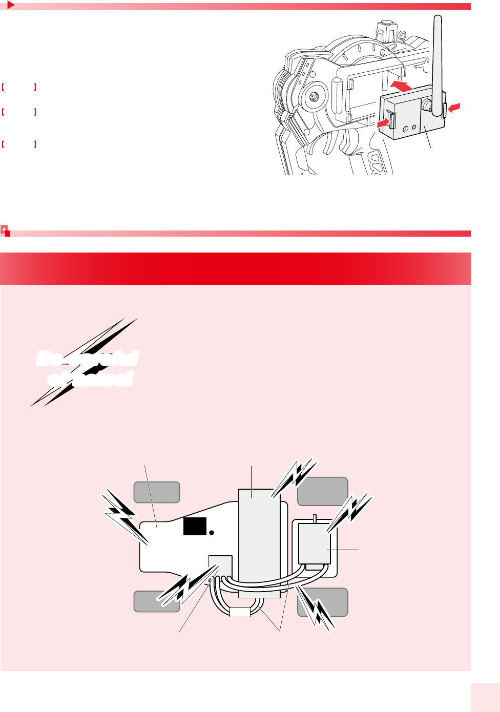
Please exchange modules to change frequency band
(2.4GHz,27MHz,40MHz).
Please read the handling manual of the module attachment well
when you use it.
Remove the RF module and replace them as required.
When removing the RF module, push the right and left claws.
Please remove the rubber cap of the main body antenna, install,
and use the antenna (optional) when you use 27MHz and 40MHz.
Turn off the power of this unit when Changing the RF Module
and Crystals
Carbon chassis
Assume that all areas where large currents are flowing
are generating noise! Locate antenna cables and
receiver as far away from the motor, ESC, silicone cords
as possible. (Materials such as metal or carbon chassis
also conduct noise)
R/C model is controlled by radio wave.
Therefore,anti-noise measures are the most important
factor. Take measures to ensure optimum performance
of your R/C model and driving technique.
Battery
receiver
ESC Silicone cords
motor
NOIS
NOIS
NOISE
NOISE
NOIS
NOIS
NOIS
NOIS
NOIS
NOIS
Locate antenna cable as far away from noise source!
Be careful
of noise!
Be careful
of noise!
Changing the RF Module and Crystals
Notes on installing receiver (anti-noise measures)
RF Module
Coution!
Coution!
Coution!
11
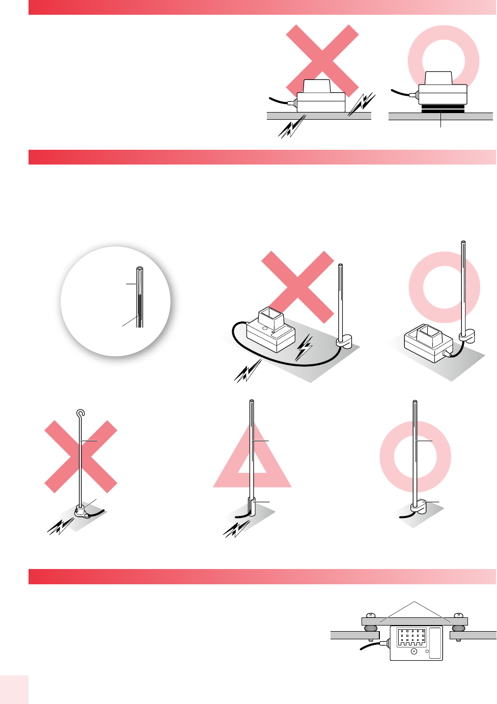
When fixing the receiver to the chassis or on the mechanism
deck, use more than 2 layers of doublesided tape to avoid
direct contact with chassis. Chassis and mechanism deck
(especially carbon material) can also conduct noise. Making
space between receiver with them is recommend to ensure
protection against noise.
Raise antenna cable vertically and set as high as possible. Pass cable into antenna pipe to protect from damage. Be sure
that the cable projects a bit from antenna pipe. Installing antenna holder far away from receiver may deteriorate radio
sensitivity. Locate antenna holder as near to the receiver as possible. Make sure that the antenna cable does not come in
direct contact with chassis, mechanism plate or other noise sources. Make sure to use plastic antenna pipe and mount. Do
not use metal antenna mount as it easily conducts noise and result in trouble.
Engine vibration may damage the servo. Make sure to attach
grommet (receiver holder) to reduce vibration. Do not attach
directly to chassis or mechanism plate using double-sided tape.
The installation position should be as far as possible from heat
from engine or exhaust.
Plastic antenna pipe Plastic
antenna pipe
Plastic holder
Grommet
Aluminum holder
Aluminum holder
Piano wire
Double sided tape
Antenna Cable
Antenna
NOISE
NOISE
NOISE
NOISE
NOISE
NOISE
NOISE
NOISE
NOISE
NOISE
(FRP or plastic holder can be used.)Soldering lug plate
● Fixing receiver to carbon chassis
● Antenna installation
● Attaching to a gas car
�Note receiver LED position when installing.
�Note receiver LED position when installing.
NOISE
NOISE
�Do not cut or bundle antenna cable
(It may result in breaking of wire and deteriorate
performance)
12
Within 1M
while pressing
the setup button
POWER ON
ON
How to pairing
If the pairing fails it may be due to a wireless LAN, microwave oven or
someone else trying to pair at the same time. Please move to another
location where you can try the pairing again.
Read instructions included with servo and speed controller before connection and usage.
Adjust steering and throttle/brake settings
4.
Adjust failsafe.
5.
Register the transmitter to the receiver to complete “pairing(as follows “How to
pairing”)
3.
IInstall batteries (R6/AA/UM3 size batteries x 8) to transmitter, then install running battery to
electric R/C car. For gas R/C car, install
receiver batteries.
2.
Install receiver, servo, ESC (when using with electric car) and connect cables. Install receiver
noting anti-noise measures.
1.
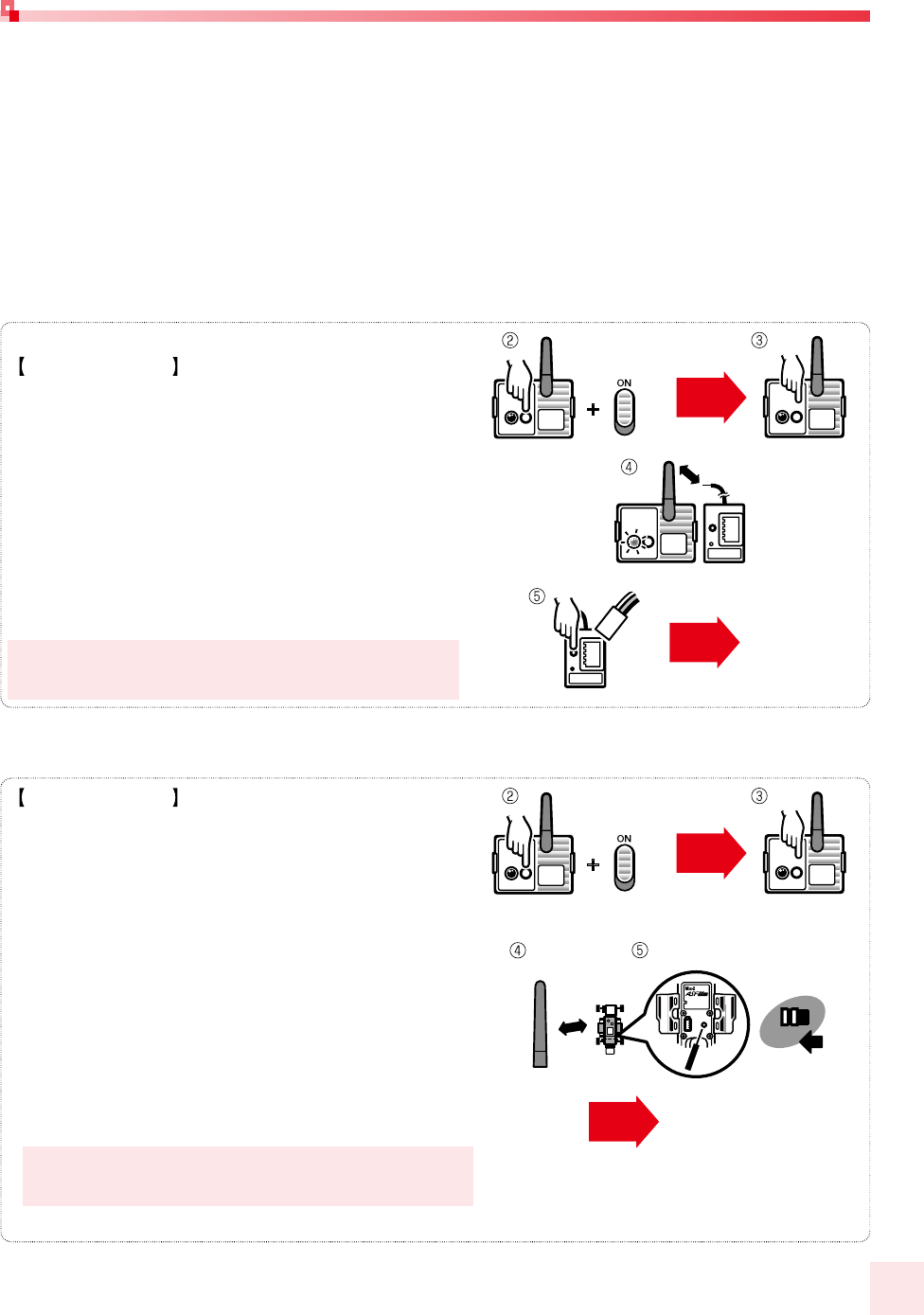
1.Install the RF-902S module in the transmitter and raises
the antenna.
2.While the set button of module is pushed, power of the
transmitter is turned on. At this time the LED light of
module lights up.
3.After approximately 3 seconds, the LED light will go out. When
LED goes out is verified, please release the set button.
4.The Receiver is brought close to the transmitter (within 1M).
5.While pressing the pairing button on the receiver, turn ON the
power source.
6.Release the pairing button when the LED indicator lights up and
the pairing is completed. Please turn off the power of the
transmitter and the receiver.
Unit preparation
lights up
Complete
within 1M
from Battery
Receiver
LED of
light ON
Note polarity and install fresh batteries. Depleted batteries may deteriorate radio power and
cause problems.
Case of RF-902S
How to pairing
If the pairing fails it may be due to a wireless LAN, microwave oven or
someone else trying to pair at the same time. Please move to another
location where you can try the pairing again.
1.Install the RF-902SM module in the transmitter and raises
the antenna.
2.While the set button of module is pushed, power of the
transmitter is turned on. At this time the LED light of
module lights up.
3.After approximately 3 seconds, the LED light will go out.
When LED goes out is verified, please release the set
button.
4.The chassis is brought close to the transmitter (within
1M).(As for a detailed procedure, please refer to the
instruction manual of the chassis.)
5.While pressing the pairing button on the chassis, turn ON
the power source.
6.Release the pairing button when the LED indicator lights up
and the pairing is completed. Please turn off the power of
the transmitter and the receiver.
lights up
Complete
chassis
LED of
light ON
Case of RF-902SM (for Mini-Z)
13
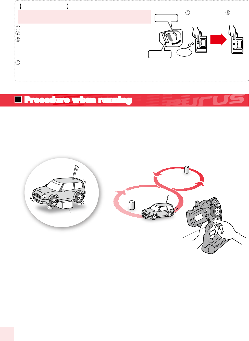
Checking model:Confirm model to be used.
2.
Power on: Note surroundings and switch transmitter on, then switch receiver on.
1.
Checking movements:
Raise wheels from ground and operate transmitter to check movements.
Detail adjustment using steering/throttle trim lever should be done while running.
Adjust steering balance by operating 8-figure running.
3.
Power off:
Switch off in receiver, transmitter order and remove running battery.
4.
Make sure to switch the transmitter on and off after an interval of at least 2 seconds.
Stand
8-figure running
Trim lever
Failsafe setting
Switch transmitter on.
Switch receiver on and check servo movement.
Operate throttle trigger in brake/neutral position
(transmitter memorizes the position) Hold set button of
receiver more than 3 seconds.
Release after LED turns off.
Release Button
3 seconds
Turn Off
LED
neutral
full brake
Failsafe automatically returns throttle (2ch) in desired position
(full brake/neutral) if the model may run out of control.
Failsafe function can be checked by switching off transmitter. The
data will be memorized until resetting.
When replacing brake linkage of a gas car, resetting is
recommended.
Throttle trigger
(full brake/neutral)
Set button (hold 3
seconds)
14
Procedure when running
Transmitter: KT-409H
Operation method:Wheel + trigger method
Number of channels:4 channels
Transmission frequency range:Any frequency range is
available by replacing the RF module
Neutral pulse:1.5mSec
Power supply:8xAA size dry cells or 8-cells battery pack
Current consumption:Less than 80mA (high frequency
range is not included)
RF module:RF−902S or RF-902SM
Modulation:DSSS
Transmission frequency:2.4GHz
Receiver:KR-409S
Reception method:DSSS
Number of channels:4 channels
Reception frequency:2.4GHz
Operating voltage:3.5-7.4V
Dimensions:28x18.3x18.5mm
Weight:7.5g
THIS DEVICE COMPLIES WITH PART 15 OF THE FCC
RULES. OPERATION IS SUBJECT TO THE FOLLOWING
TWO CONDITIONS: (1) THIS DEVICE MAY NOT CAUSE
HARMFUL INTERFERENCE, AND (2) THIS DEVICE
MUST ACCEPT ANY INTERFERENCE RECEIVED,
INCLUDING INTERFERENCE THAT MAY CAUSE
UNDESIRED OPERATION.
SPECIFICATIONS