Konica Minolta Dimage Scan Elite F 2900 Instruction Manual 9224 2885 11 H A909
F-2900 to the manual 251c54a2-e3a8-4608-aed8-adc5245a5b30
2014-12-13
: Konica-Minolta Konica-Minolta-Dimage-Scan-Elite-F-2900-Instruction-Manual-124539 konica-minolta-dimage-scan-elite-f-2900-instruction-manual-124539 konica-minolta pdf
Open the PDF directly: View PDF ![]() .
.
Page Count: 85
9224-2885-11 H-A909
EINSTRUCTION MANUAL

Thank you for purchasing the Minolta Dimâge Scan Elite. The Dimâge Scan Elite F-2900 is a dual
format film scanner capable of scanning 35mm and with the optional AD-10 APS Adapter,
Advanced Photo System film.
This manual has been designed to help you understand the operation of your scanner. Please read
this manual thoroughly to realise all the benefits of your scanner.
The instructions in this manual assume you have a working knowledge of the operating system for
your computer (Macintosh OS, Windows 95, Windows 98, or Windows NT) and its conventions.
Familiarity with the mouse and standard operating system menus and commands is necessary
before operating the driver software for the Dimâge Scan Elite.
This manual does not instruct in the:
• basic use of personal computers.
• use of Windows 95, Windows 98, Windows NT, or Macintosh OS.
• use of Adobe Photoshop, Paint Shop Pro, or Corel Draw.
The examples in this manual use Windows 95. The appearance of some screens may differ from
the examples when using Windows 98, Windows NT, or the Macintosh operating system.
This mark certifies that this product meets the requirements of the EU (European
Union) concerning interference causing equipment regulations. CE stands for
Conformité Européenne.
This Class B digital apparatus complies with Canadian ICES-0003.
Cet appareil numérique de la classe B est comforme à la norm NMB-003 du Canada.
• Changes or modifications not approved by the party responsible for compliance could void the user’s authority to
operate the equipment.
• This manual may not be copied in part or whole without prior written permission from Minolta Co., Ltd. ©1999
Minolta Co., Ltd.
• Every necessary caution has been taken to ensure the accuracy of this instruction manual. Please contact us if
you have any questions, find any errors, or notice missing information.
• Minolta is not responsible for loss, damage, or other results occurring during the operation of this product.
Tested by the Minolta Corporation 101 Williams Drive Ramsey, New Jersey 07446 USA
This device complies with Part 15 of the FCC Rules. Operation is
subject to the following conditions: (1) This device may not cause
harmful interference, and (2) this device must accept any interference
received, including interference that may cause undesired operation.
To meet FCC regulations, the SCSI cables used with this scanner
must be equipped with ferrite cores.
Microsoft, Windows®, Windows 95®, Windows 98®, and Windows NT®are registered trademarks
of the Microsoft Corporation.
Macintosh™, Apple®, and Power Macintosh®are registered trademarks of Apple Computer, Inc.
Adobe®and Photoshop™ are registered trademarks of Adobe Systems Incorporated.
Corel Draw™ is a trademark of the Corel Corporation.
Paint Shop Pro is the copyright of Met’s Corporation.
Other corporate and product names are the trademarks and registered trademarks of their
respective companies.
1
FOR PROPER AND SAFE USE
Please read and understand each caution before using this product.
To avoid fire or electric shock:
• Use only within the voltage range specified on the back of unit.
• Do not expose this unit to liquids.
• Do not insert metal objects into this unit.
• Do not touch the cord or plug if your hands are wet.
• Unplug this unit when it is not in use.
Improper use of the power cord may result in fire or electric shock.
• Insert the plug securely into an electrical outlet.
• Do not pull on the cord. Grasp the plug when removing the power cord from an outlet.
• Do not scratch, twist, modify, heat, or place a heavy object on the power cord.
• Do not connect the ground to a gas pipe, telephone ground, or a water pipe. Improper
grounding can result in electric shock.
This product must have sufficient ventilation while in use. Blocked ventilation
ducts may cause the unit to overheat, increasing the risk of fire.
• Do not use or store this product in dusty or very humid areas.
• This product should be operated in the upright position only. Do not stack any objects on this
product.
If there is smoke, a strange smell, or any other unusual conditions, shut down
and unplug the unit, then contact a Minolta Service Facility.
CAUTION
Unexpected damage may occur if this unit is left unattended near young
children.
Do not attempt to disassemble this product. It contains high-voltage
circuits.Take the product to a Minolta Service facility for repairs.
WARNING

2
SYSTEM REQUIREMENTS – PC AT
CPU:
Operating System:
Memory:
Monitor:
Other:
Windows 95 (incl. OSR2), Windows 98, or Windows NT 4.0.
A minimum of 32 MB RAM.
XGA (1024 x 768) or better. VGA (640 x 480) can be used.
SCSI Board: The following Adaptec SCSI boards are recommended for this
device:
AVA-1505AE AVA-2902E AHA-1510B
AHA-1520B AHA-1540CP AHA-2940
AHA-2940J AHA-2940U AHA-2940N
AHA-2940AU AHA-2940W AHA-2940UW
AHA-2910B AHA-2910C AHA-2920C
• The AHA-2940N SCSI board has been tested and approved for use
on NEC PC-9821 series machines.
• Do not use AVA-1505AE, AHA-1520B, and AHA-1540CP SCSI
boards with NEC PC98NX Series machines.
• Support will not be provided for malfunctions or problems caused by
the use of untested SCSI boards.
• Depending upon the SCSI board an optional adaptor may be
required.
Hard Disk Space: 90 MB of available hard disk space.
IBM PC/AT compatible with An Intel Pentium or later processor
or better.
An Intel Pentium or later when Windows NT 4.0 is installed.
• Support cannot be provided for custom or home built machines.
TWAIN driver is compatible with Photoshop ver. 3.05, 4.0.1, and
5.0.2.
Photoshop LE Ver. 5.0
Paint Shop Pro 5.0E, Corel Photo Paint 8.

SYSTEM REQUIREMENTS – MACINTOSH
3
Power PC
A minimum of 8 MB application RAM in addition to the
requirements for the Mac OS and Adobe Photoshop™
13 inch monitor capable of displaying 32,000 colors.
CPU:
Operating System:
Memory:
Monitor:
Other:
Hard Disk Space: 90 MB of available hard disk space.
Mac OS 7.5 to 8.6
Standard SCSI board (SCSI expeansion card inserted in
PCI/NuBus must not be used)
New Power Macintosh G3 series (Blue and White) use:
Adaptec PowerDomain 2940UW, PowreDomain 1940U2W,
PowerDomain 2930U or SCSI Card 2906.
SCSI board:
Plug-in is compatible with Photoshop ver. 3.05, ver. 4.01 or
ver.5.02.
Photoshop LE Ver. 5.0.
ColorSync profile (DS Elite profile) is included.
Turn off Virtual Memory and the Modern Memory Manager.
4
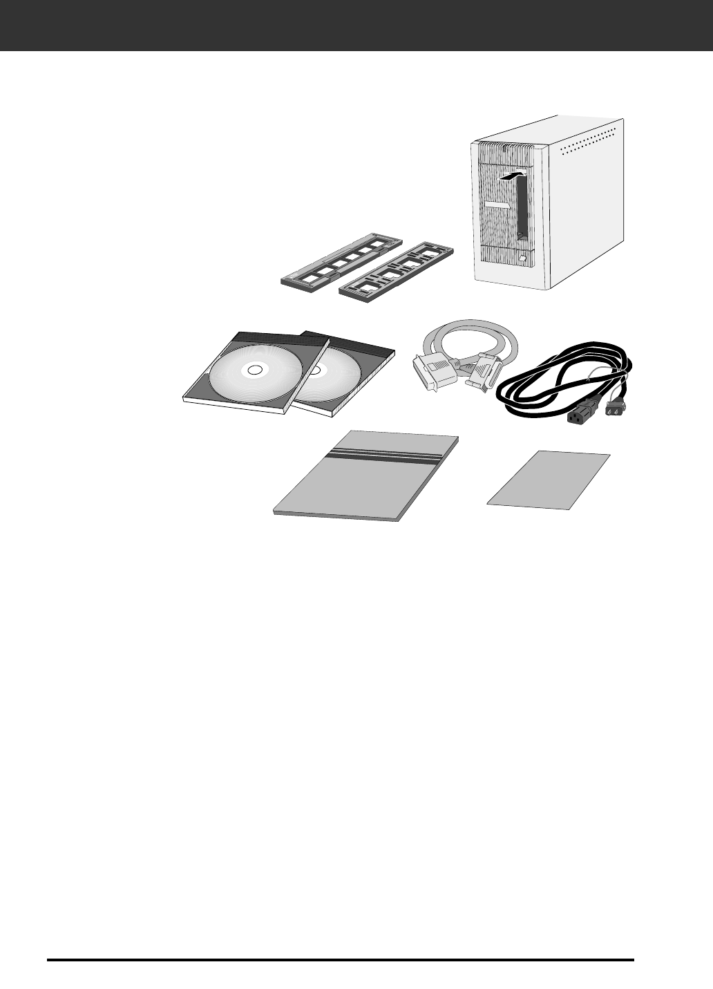
PACKAGE CONTENTS
1. Minolta Dimâge Scan Elite
2. 35mm Slide and Negative holders
3. SCSI cable SC-11
4. AC power cord
5. DS_Elite driver software and manuals CD ROM
6. Quick Reference Guide
7. Warranty card
8. Photoshop LE CD ROM
The following contents should be included in this package.
Software Registration
Please register this software before using it…
Once registered, you will receive technical support, software upgrade and product
information. Complete and return the enclosed Product & Software Registration form
after detaching it form the Warranty. No postage is necessary.
• The information you provide is confidential and will only be used by Minolta Customer Service and Product
Research & Development.

5
TABLE OF CONTENTS
FOR PROPER AND SAFE USE . . . . . . . . . . . . . . . . . . . . . . . . . . . . . . . . . . . . . . . . . . . . .1
SYSTEM REQUIREMENTS PC/AT . . . . . . . . . . . . . . . . . . . . . . . . . . . . . . . . . . . . . . . . . . .2
SYSTEM REQUIREMENTS Macintosh . . . . . . . . . . . . . . . . . . . . . . . . . . . . . . . . . . . . . . . .3
PACKAGE CONTENTS . . . . . . . . . . . . . . . . . . . . . . . . . . . . . . . . . . . . . . . . . . . . . . . . . . . .4
TABLE OF CONTENTS . . . . . . . . . . . . . . . . . . . . . . . . . . . . . . . . . . . . . . . . . . . . . . . . . . . .5
NAMES OF PARTS . . . . . . . . . . . . . . . . . . . . . . . . . . . . . . . . . . . . . . . . . . . . . . . . . . . . . . .6
SCANNER SETUP
Setting the SCSI ID . . . . . . . . . . . . . . . . . . . . . . . . . . . . . . . . . . . . . . . . . . . . . . . . . . . . . . . . . . .8
Connecting the Hardware . . . . . . . . . . . . . . . . . . . . . . . . . . . . . . . . . . . . . . . . . . . . . . . . . . . . . .9
Installing the Software PC/AT . . . . . . . . . . . . . . . . . . . . . . . . . . . . . . . . . . . . . . . . . . . . . . . . . .12
Installing the Software Macintosh . . . . . . . . . . . . . . . . . . . . . . . . . . . . . . . . . . . . . . . . . . . . . . .15
STANDARD OPERATION
Launching the Software . . . . . . . . . . . . . . . . . . . . . . . . . . . . . . . . . . . . . . . . . . . . . . . . . . . . . . .18
Main Window Command Window - Names of Parts . . . . . . . . . . . . . . . . . . . . . . . . . . . . . . . .
20
Setting the Preferences . . . . . . . . . . . . . . . . . . . . . . . . . . . . . . . . . . . . . . . . . . . . . . . . . . . . . . .21
Loading the Film Holder . . . . . . . . . . . . . . . . . . . . . . . . . . . . . . . . . . . . . . . . . . . . . . . . . . . . . .22
Inserting the Film Holder into the Scanner . . . . . . . . . . . . . . . . . . . . . . . . . . . . . . . . . . . . . . . . .24
Setting the Film Type . . . . . . . . . . . . . . . . . . . . . . . . . . . . . . . . . . . . . . . . . . . . . . . . . . . . . . . . .25
Prescan . . . . . . . . . . . . . . . . . . . . . . . . . . . . . . . . . . . . . . . . . . . . . . . . . . . . . . . . . . . . . . . . . .26
Auto-Exposure Lock . . . . . . . . . . . . . . . . . . . . . . . . . . . . . . . . . . . . . . . . . . . . . . . . . . . . . . . . .27
AE Area Lock . . . . . . . . . . . . . . . . . . . . . . . . . . . . . . . . . . . . . . . . . . . . . . . . . . . . . . . . . . . . . .28
Orienting the Image . . . . . . . . . . . . . . . . . . . . . . . . . . . . . . . . . . . . . . . . . . . . . . . . . . . . . . . . .29
Image Correction . . . . . . . . . . . . . . . . . . . . . . . . . . . . . . . . . . . . . . . . . . . . . . . . . . . . . . . . . . .34
Image Correction - Tone Curves/Histogram . . . . . . . . . . . . . . . . . . . . . . . . . . . . . . . . . . . . . . .35
Image Correction - Brightness/Contrast/Color Balance . . . . . . . . . . . . . . . . . . . . . . . . . . . . . . .40
Image Correction - Hue/Saturation/Lightness . . . . . . . . . . . . . . . . . . . . . . . . . . . . . . . . . . . . . . .42
Image Correction - Variation Correction . . . . . . . . . . . . . . . . . . . . . . . . . . . . . . . . . . . . . . . . . . .44
Image Correction - Snapshot . . . . . . . . . . . . . . . . . . . . . . . . . . . . . . . . . . . . . . . . . . . . . . . . . . .47
Image Correction - Full-Screen View . . . . . . . . . . . . . . . . . . . . . . . . . . . . . . . . . . . . . . . . . . . . .48
Image Correction Job - Job Save/Job Load . . . . . . . . . . . . . . . . . . . . . . . . . . . . . . . . . . . . . . . .49
Navigation . . . . . . . . . . . . . . . . . . . . . . . . . . . . . . . . . . . . . . . . . . . . . . . . . . . . . . . . . . . . . . . . .51
Final Scan . . . . . . . . . . . . . . . . . . . . . . . . . . . . . . . . . . . . . . . . . . . . . . . . . . . . . . . . . . . . . . . .54
SCANNING APS FILM
Launch Software . . . . . . . . . . . . . . . . . . . . . . . . . . . . . . . . . . . . . . . . . . . . . . . . . . . . . . . . . . . .56
Specify Film Type . . . . . . . . . . . . . . . . . . . . . . . . . . . . . . . . . . . . . . . . . . . . . . . . . . . . . . . . . . .56
Preferences - APS Settings . . . . . . . . . . . . . . . . . . . . . . . . . . . . . . . . . . . . . . . . . . . . . . . . . . . .57
APS Adapter - Names of Parts . . . . . . . . . . . . . . . . . . . . . . . . . . . . . . . . . . . . . . . . . . . . . . . . .58
Loading the APS Adapter . . . . . . . . . . . . . . . . . . . . . . . . . . . . . . . . . . . . . . . . . . . . . . . . . . . . .58
Inserting the APS Adapter into the Scanner . . . . . . . . . . . . . . . . . . . . . . . . . . . . . . . . . . . . . . . .59
Index Scan . . . . . . . . . . . . . . . . . . . . . . . . . . . . . . . . . . . . . . . . . . . . . . . . . . . . . . . . . . . . . . . .60
Index tab – Names of Parts . . . . . . . . . . . . . . . . . . . . . . . . . . . . . . . . . . . . . . . . . . . . . . . . . .60
Preview and Image Correction . . . . . . . . . . . . . . . . . . . . . . . . . . . . . . . . . . . . . . . . . . . . . . . . . .63
Scanning the Image . . . . . . . . . . . . . . . . . . . . . . . . . . . . . . . . . . . . . . . . . . . . . . . . . . . . . . . . .64
Removing the APS Adapter . . . . . . . . . . . . . . . . . . . . . . . . . . . . . . . . . . . . . . . . . . . . . . . . . . . .65
APPENDIX
Color Matching . . . . . . . . . . . . . . . . . . . . . . . . . . . . . . . . . . . . . . . . . . . . . . . . . . . . . . . . . . . . .68
Scan Settings . . . . . . . . . . . . . . . . . . . . . . . . . . . . . . . . . . . . . . . . . . . . . . . . . . . . . . . . . . . . . .70
Creating/Deleting Scan Job Files . . . . . . . . . . . . . . . . . . . . . . . . . . . . . . . . . . . . . . . . . . . . . . . .73
Scan Job File List . . . . . . . . . . . . . . . . . . . . . . . . . . . . . . . . . . . . . . . . . . . . . . . . . . . . . . . . . . .75
Glossary . . . . . . . . . . . . . . . . . . . . . . . . . . . . . . . . . . . . . . . . . . . . . . . . . . . . . . . . . . . . . . . . . .78
Trouble Shooting . . . . . . . . . . . . . . . . . . . . . . . . . . . . . . . . . . . . . . . . . . . . . . . . . . . . . . . . . . . .79
Specifications . . . . . . . . . . . . . . . . . . . . . . . . . . . . . . . . . . . . . . . . . . . . . . . . . . . . . . . . . . . . . .81
User Technical Support . . . . . . . . . . . . . . . . . . . . . . . . . . . . . . . . . . . . . . . . . . . . . . . . . . . . . . .82
6
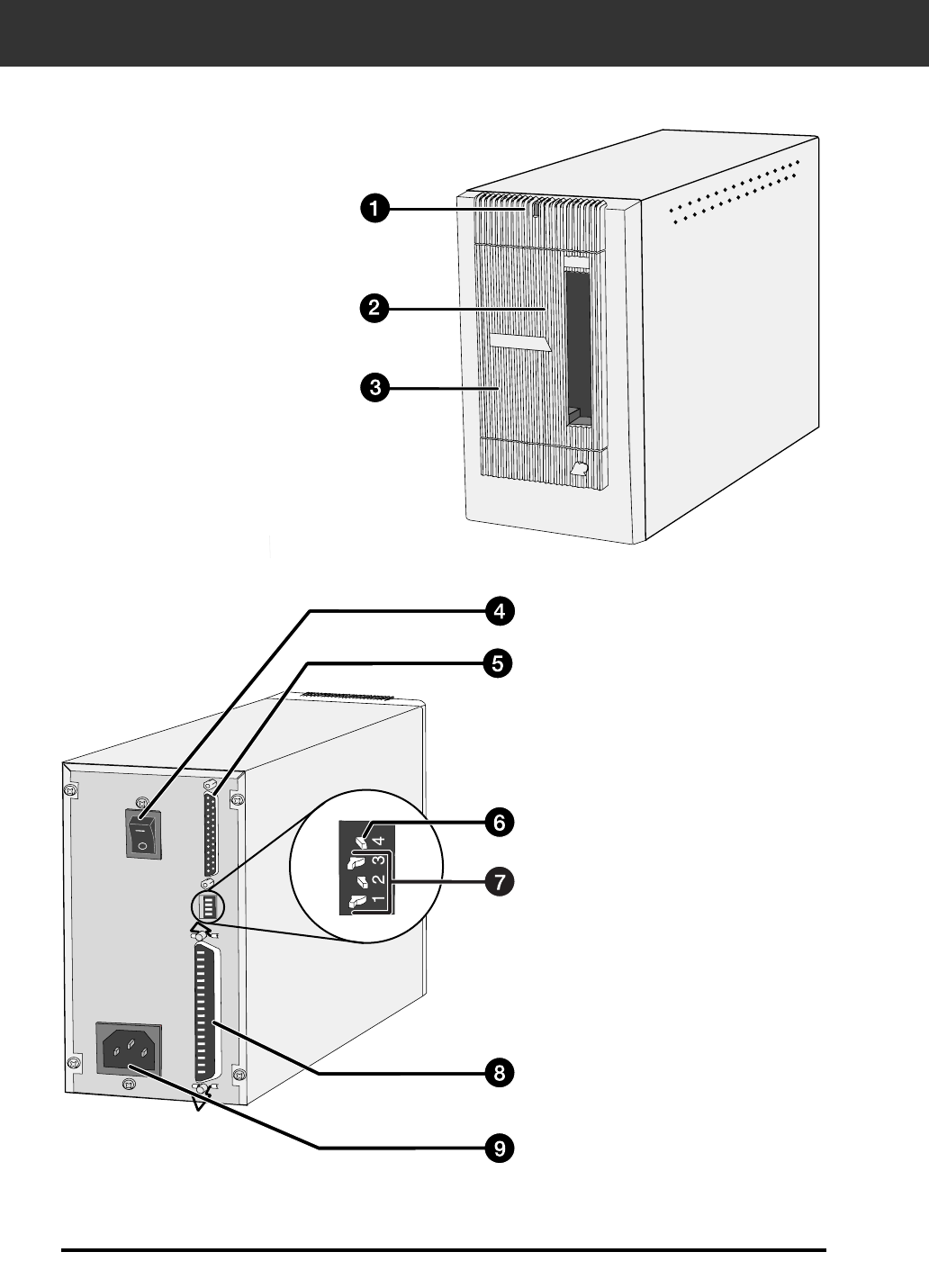
SCANNER – NAMES OF PARTS
1. Indicator lamp
2. Film slot
3. Film door
4. Power switch
5. SCSI port - DB25
6. Terminator power switch
7. SCSI ID switches
8. SCSI port - SCSI-1
9. AC socket

SCANNER SETUP
8
Setting the SCSI ID
Turn off the computer and all the devices in the SCSI chain
before changing SCSI IDs, connecting, or disconnecting SCSI
cables. Hardware damage may occur if this precaution is not
followed.
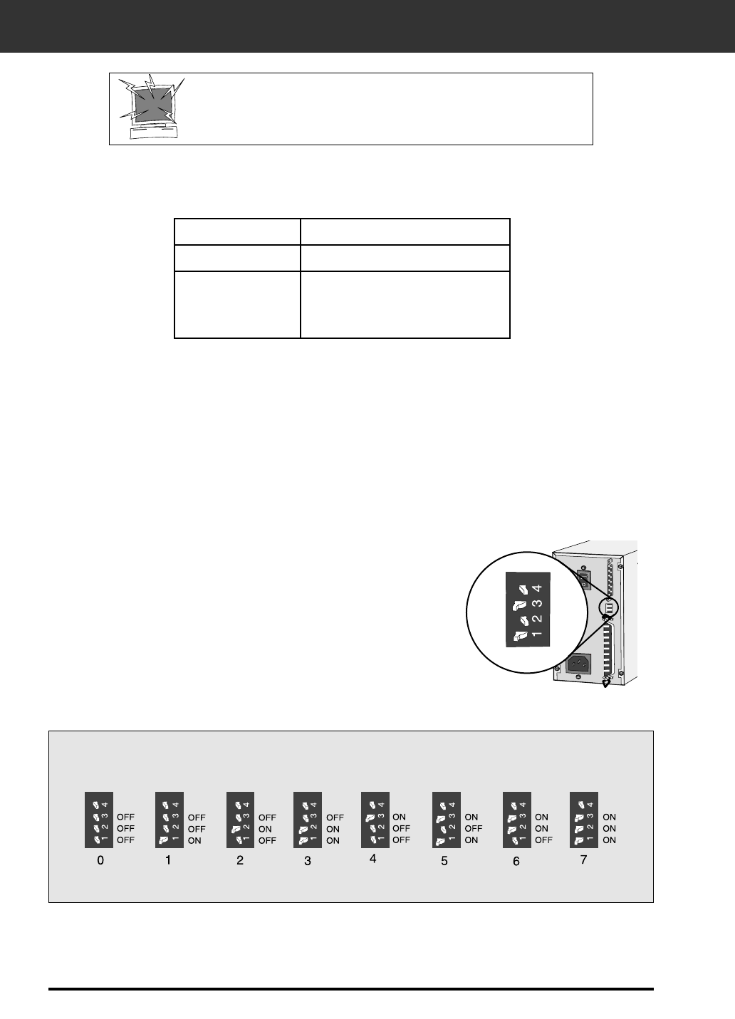
SETTING THE SCSI ID
A SCSI ID is a unique address you assign to each SCSI device connected to your computer. The
SCSI ID range of your computer is from 0 to 7, however some ID's are already occupied.
1. Turn off the computer and all connected SCSI
devices.
SCSI ID Dip Switch Settings
3. Using a pointed object, set the switches to an
unused SCSI ID.
• The Dimâge Scan Elite’s SCSI ID is factory preset to 5. If 5 is not
occupied, there is no need to change the SCSI ID.
• Two operating SCSI devices in the same SCSI chain cannot share a
SCSI ID.
2. Determine which SCSI IDs are not being used.
IBM PC/AT
Macintosh
Occupied SCSI ID
7 - SCSI host adapter
0 - internal hard drive*
3 - internal CD ROM drive**
7 - operating system
* IDE Macintosh systems do not use SCSI ID 0 for the hard drive.
** SCSI ID 3 is available on the external bus on Macintosh systems with a dual bus.
9
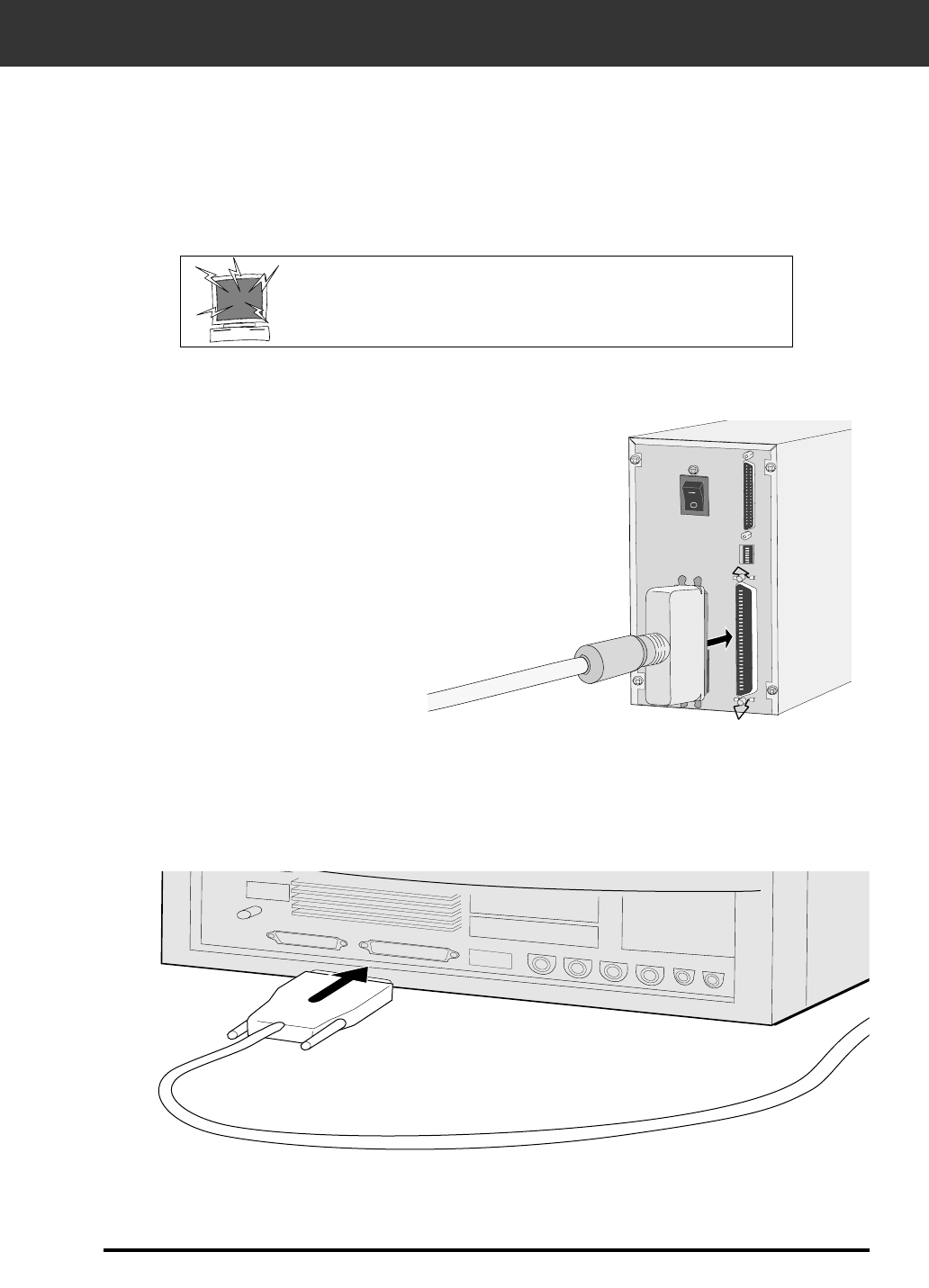
CONNECTING THE HARDWARE
2. Connect one end of the SCSI cable to either SCSI
port on the back of the scanner
• Either SCSI port can be used for other configurations, there is no
dedicated in or out port.
1. Place the scanner on a level surface.
3. Connect the other end of the SCSI cable to the
SCSI port on the computer or the last device in
the SCSI chain.
Continued on the following page.
Connecting the SCSI Cable
This scanner has been packaged with the SCSI cable SC-11 (DB25-to-SCSI-1). See your dealer if
you require a different SCSI cable.
• To meet FCC regulations, the SCSI cables used with this scanner must be equipped with ferrite cores.
BEFORE YOU BEGIN…
TURN THE COMPUTER AND ALL CONNECTED
DEVICES OFF.
10
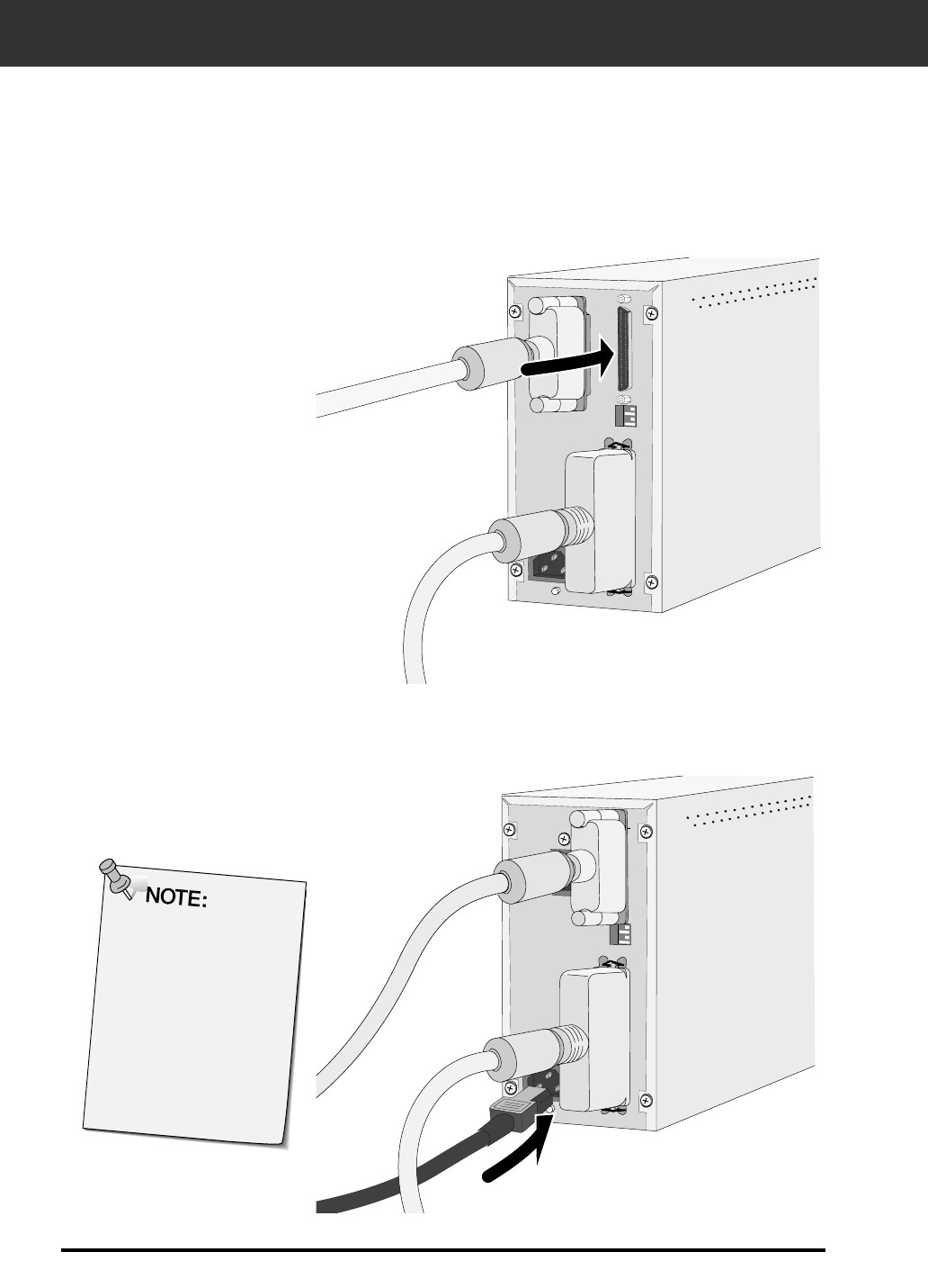
CONNECTING THE HARDWARE
4. Plug the SCSI cable from the next device into the
open port on the back of the scanner.
If there are other devices in your
SCSI chain…
5. Plug the power cord into the scanner’s AC socket,
then plug it into a grounded outlet.
This decive is to be
used with a power
source within the
voltage as specified on
the back of unit.
11
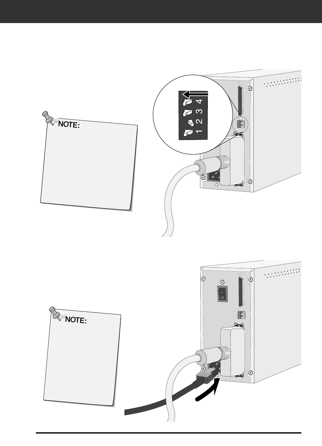
Terminating the SCSI chain
helps to suppress electronic
noise in the SCSI chain.
Not terminating the SCSI chain
can cause slowdowns, data
errors, crashes, and other
unpredictable errors.
5. Plug the power cord into the scanner’s AC
socket, then plug it into a grounded outlet.
4. Turn the terminator power switch
(switch 4) to ON.
• An external terminator is not necessary with
this scanner.
If the Dimâge Scan Elite is the last or
only device in your SCSI chain…
CONNECTING THE HARDWARE
This decive is to be
used with a power
source within the
voltage as specified on
the back of unit.
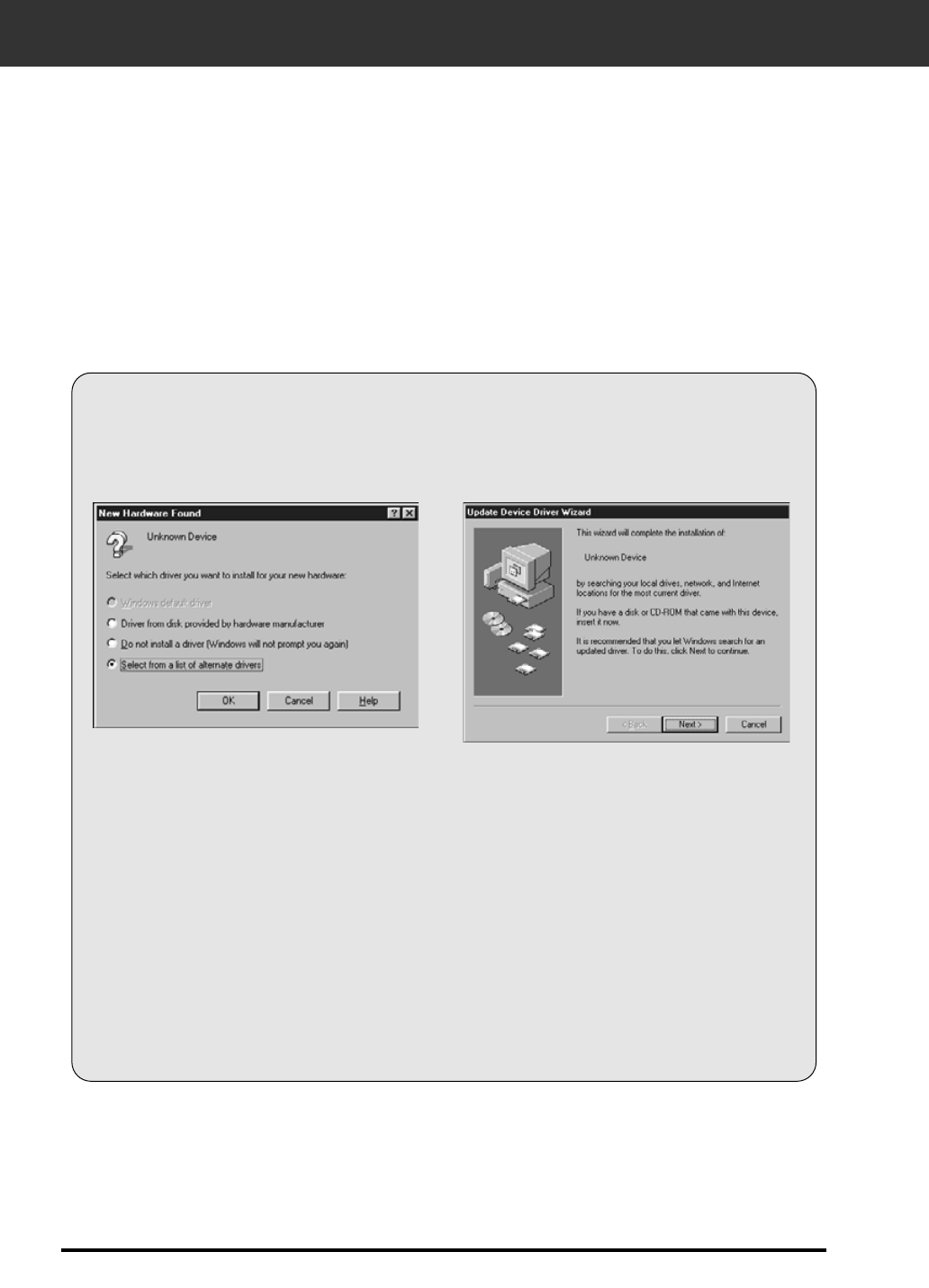
• The Device Wizard dialog box will appear.
INSTALLING THE SOFTWARE – PC/AT
12
WINDOWS 95/ WINDOWS 98 WINDOWS NT
1. Turn on the scanner, then turn on the PC.
2. Start the Windows operating system.
This step varies with your specific operating software...
Windows 95 Windows 95 Release 2 (OSR2)
and Windows 98
• The New Hardware Found dialog box will
appear.
3. Click on Cancel.
• This dialog box may appear several times.
Repeat step 3 until the dialog box no longer
appears.
3. Click on Next until the Unknown
Device window appears…
…then click on Finish.
• This dialog box may appear several times.
Repeat step 3 until the dialog box no longer
appears.
Windows NT
3. Select Start > Settings > Control Panel, then double-click on the SCSI
Adapters icon. Confirm that Minolta #2885 appears as a connected
device for your SCSI board.
• If Minolta #2885 does not appear, turn the system off and check all the connections. Repeat the
procedure.
4. Insert the Dimâge Scan Elite CD-ROM into the CD-
ROM drive.
Dimâge Scan Elite for Windows Setup installs the Twain and Twain_32 driver software into the drive
and folder you select.
• The appearance and/or wording of some dialog boxes may vary depending on the version of Windows running
on your machine.
• These installation instructions assume drive D is the CD-ROM drive.
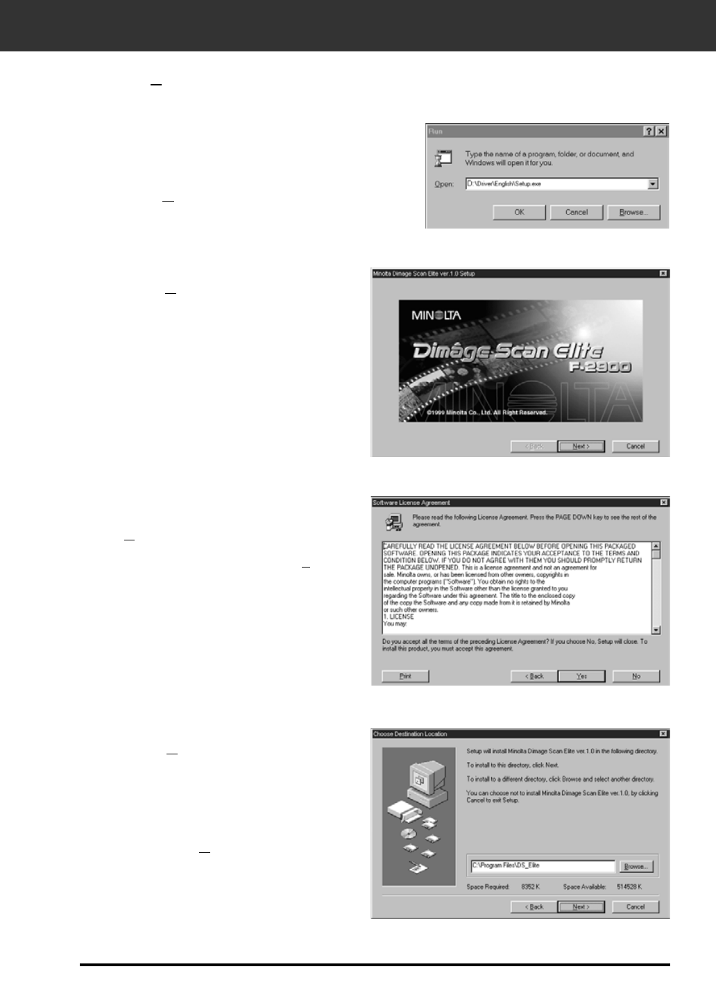
then click on Next.
9. Click on Browse to select another
destination directory…
• An install directory and path can also be entered
directly into the install path list box.
8. After reading the agreement, click
on Yes.
• If you do not agree to the conditions stated in the
End-User License Agreement, click on No and the
software will not be installed.
6. Select
D:\DRIVER\ENGLISH\Setup.exe
from the Open drop-down list, then
click on OK.
• If your CD-ROM drive is not the D drive, replace
the D with the appropriate designation for your
CD-ROM drive.
INSTALLING THE SOFTWARE – PC/AT
13
5. Select Run form the Start menu.
The Run dialog box will appear.
The Software License Agreement will appear.
The Choose Destination Location dialog box will appear.
Continued on the following page.
7. Click on Next.
The installer flash will appear.
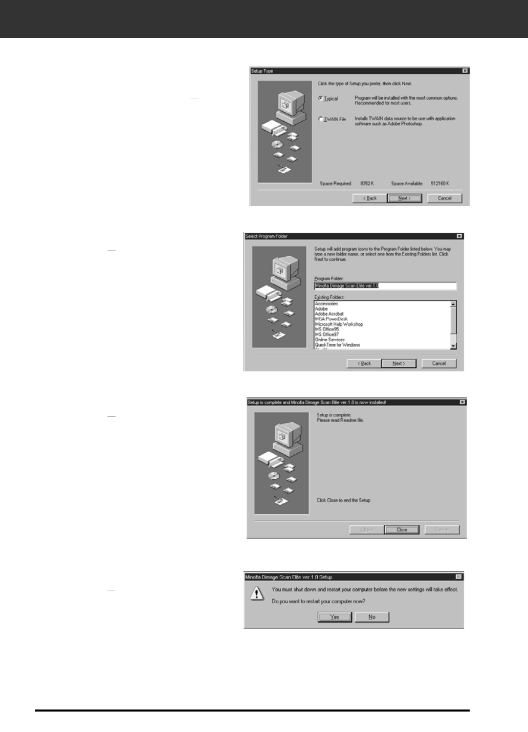
13. Click on Yes.
12. Click on Close.
11. Click on Next.
• Setup will begin.
INSTALLING THE SOFTWARE – PC/AT
14
10. Choose either Typical or TWAIN
Files install, then click on Next.
The Setup Type dialog box will appear.
The Select Program Folder dialog box will appear.
The Setup Successful dialog box will appear.
The following dialog box will appear.
INSTALLING THE SOFTWARE – MACINTOSH
15
1. Turn on the Dimâge Scan Elite, then turn on your Macintosh.
2. Quit any open applications.
3. Insert the Dimâge Scan Elite CD-ROM into the CD-ROM drive.
• will appear on the desktop.
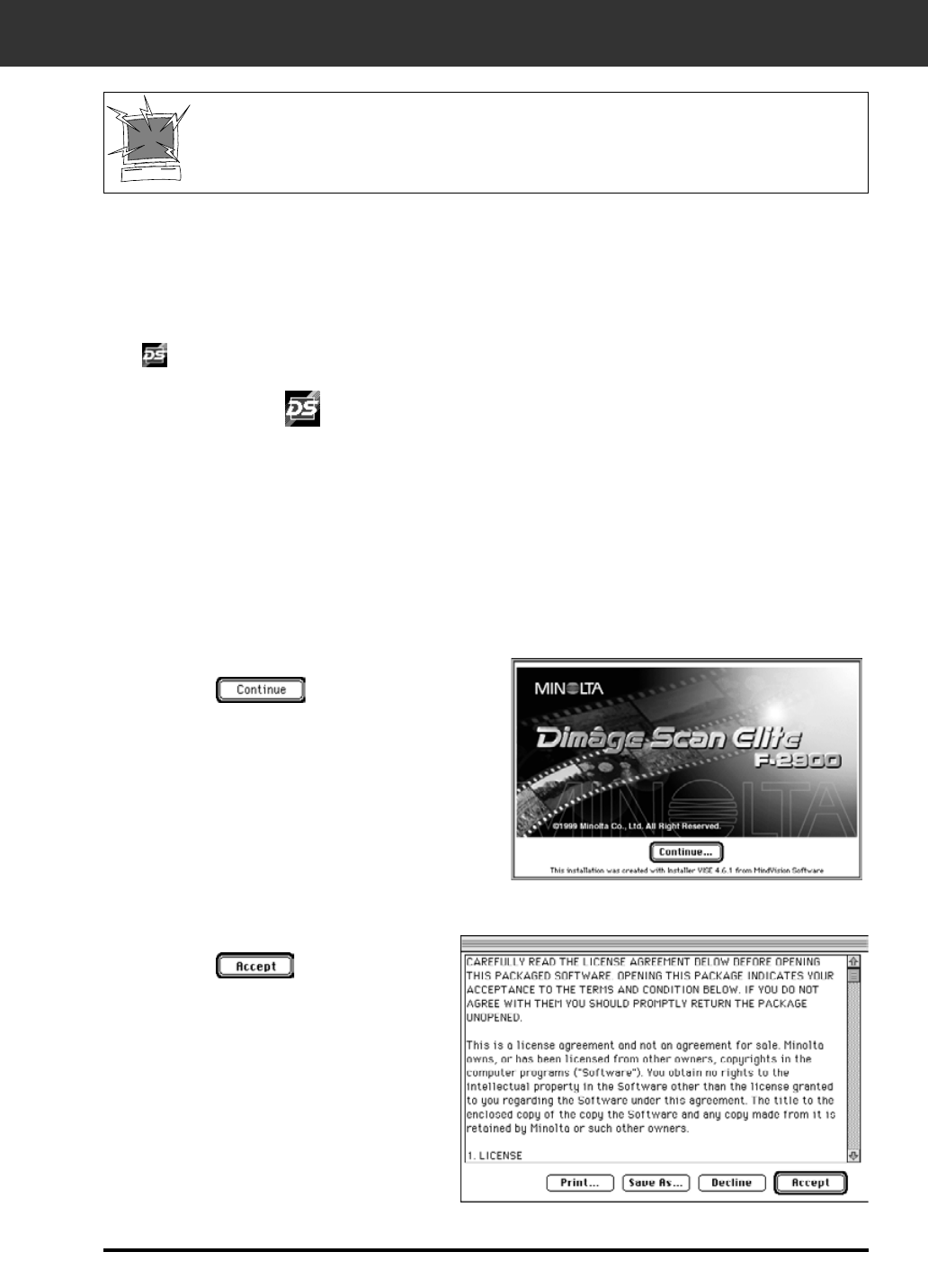
4. Double-click on .
• The driver folders will appear.
7. Click on .
8. Click on .
• If you do not agree to the
conditions stated in the
End-User License
Agreement, click on
Decline and the software
will not be installed.
The End-User License Agreement will appear.
The installer’s start-up screen will appear.
6. Open the English language folder, then double click on the Dimâge Scan Elite
Installer.
Continued on the following page.
Please remove or disable any antivirus system extensions before launching this
installer. These extensions may conflict with the operation of this installer. Replace
or re-enable them when installation is complete. Hold the shift key down during
startup to disable the extensions.
5. Double-click on Driver folder.
• The language folders will appear.
16
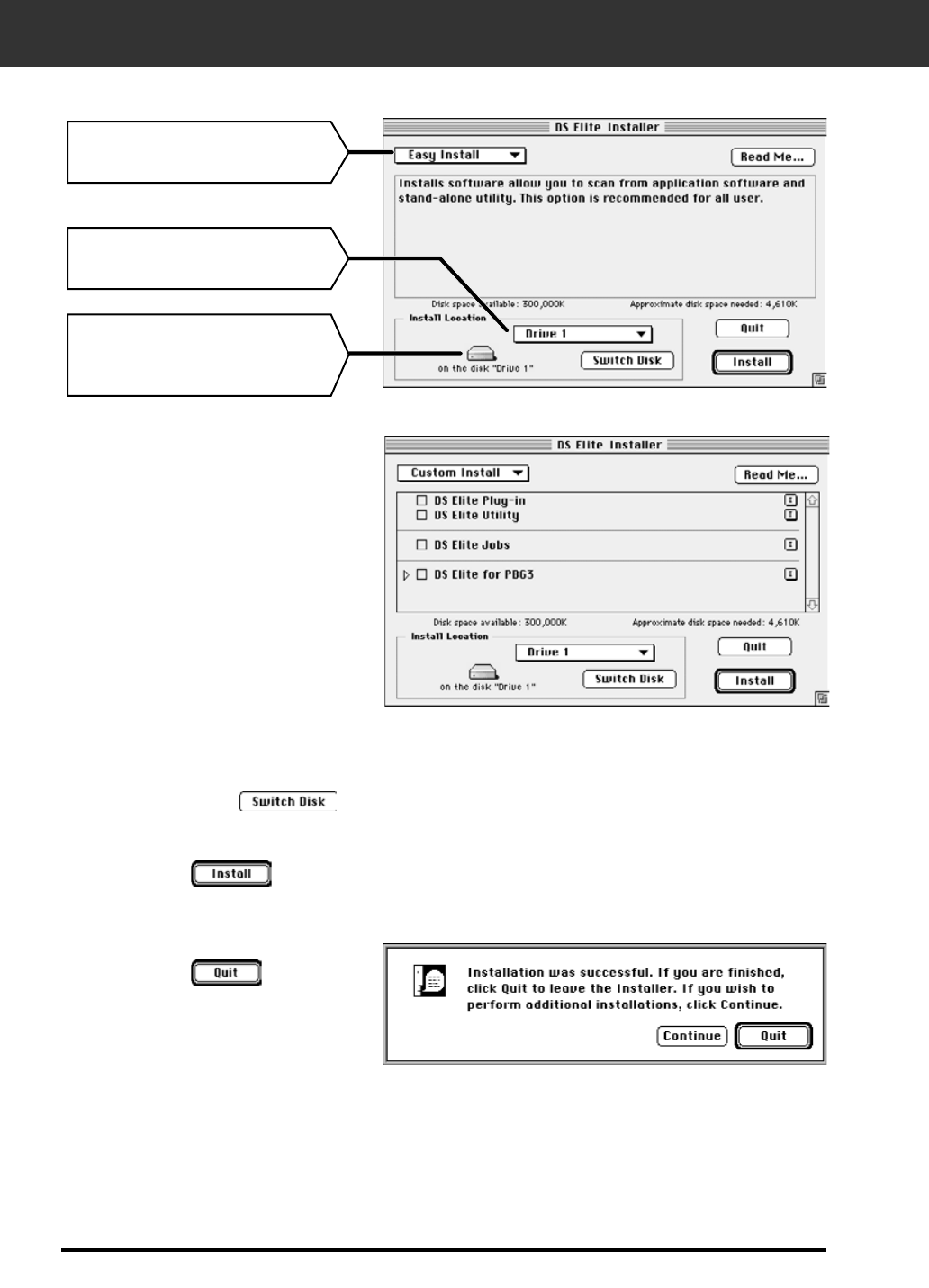
10. Click on .
11. Click on .
• The software will be installed in a new
folder titled Dimâge Scan Elite.
• If Easy Install was chosen, the Dimâge
Scan Elite folder will contain the following
items: DS_Elite Utility, DS_Elite Plug-in,
and Read Me file.
INSTALLING THE SOFTWARE – MACINTOSH
9. Select the install drive (or folder) and type from the pulldown menus.
• You can also click on to select an install drive.
The following dialog box will appear.
Install type pulldown menu
Install location pulldown menu
Name and icon of the selected
install drive or folder.
The following message appears when the installer is finished.
12. Drag the DS Elite Plug-in to the Import/Export folder in the Adobe
Photoshop Plug-ins folder.
• If you have Power Book G3, select
the DS Elite for PBG3 from the
Install type pulldown menu.
STANDARD OPERATION
SCAN FLOW
Set the Preferences
Launch the Software
Load the Film Holder
Insert the Film Holder
Specify the Film Type
Prescan
Specify the Job Type
Orient the Image
Correct the Brightness,
Contrast, and Color
Save
Scan
18
LAUNCHING THE SOFTWARE
The TWAIN driver lets you control the software through another application, such as your image
editing software.
Launching the TWAIN Driver — Windows
This manual uses Adobe Photoshop 4.0.1 as the host application. Commands may vary among
applications.
1. Open the host application.
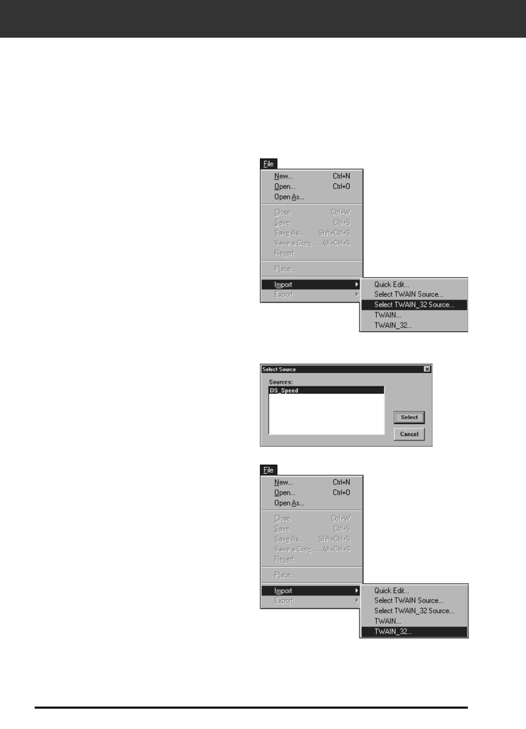
2. Select File > Import >
Select TWAIN_32 Source...
3. Select DS_Elite, then click on Select.
4. Select File > Import > TWAIN_32.
The Select Source dialog box appears.
The software is ready for use when the Main window appears (p.20).

LAUNCHING THE SOFTWARE
19
The plug-in software lets you access the software through Adobe Photoshop.
Launching the Plug-in — Macintosh
1. Launch Adobe Photoshop.
2. Photoshop 4.0.1 and newer:
Select File > Import > DS_Elite Plug-in.
Photoshop 3.0.5:
Select File > Acquire > DS_Elite Plug-in
The software is ready for use when the Main window appears (p.20).
Launching the Utility Software
Select Start > Programs > Minolta Dimâge Scan Elite > DS Elite Utility
Windows
Double click on .
Macintosh
The software is ready for use when the Main window appears (p.20).
Use the utilty software, as a stand alone application, when you just want to scan the photographic
image and store.
MAIN WINDOW—NAME OF PARTS
20
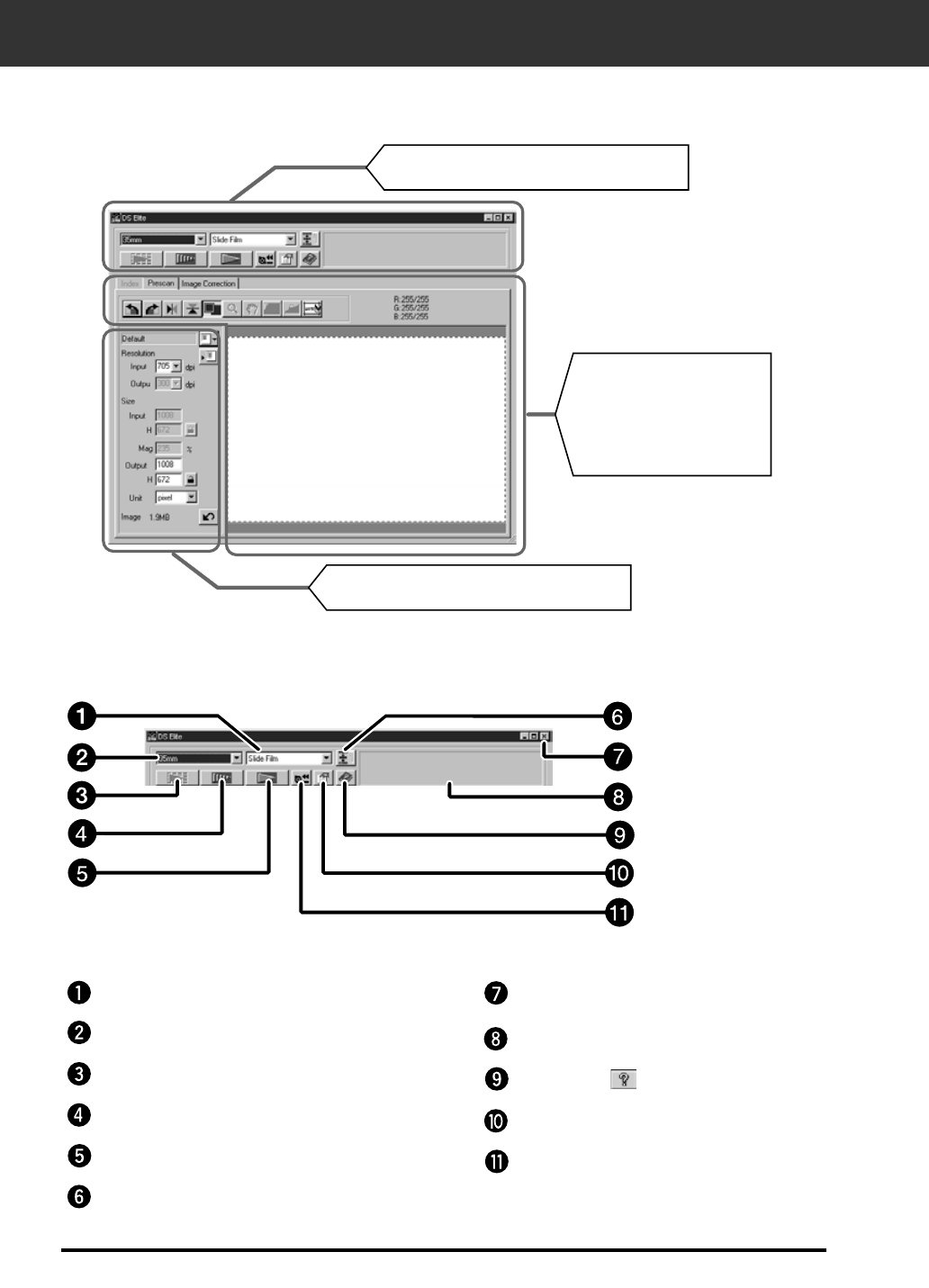
MAIN window
The Command Window part — Name of parts
Film format list box
Film format list box
Index Scan button
Prescan button
Scan button
Navigation button
Close button
Status bar
Help button ( on Macintosh)
Preferences button
APS Rewind button
Index scan (see page 56)
/ Prescan (see page 26) /
Image Correction (see
page 34) tab part
Scan Setting part (see page 68)
Command Window part (see below)
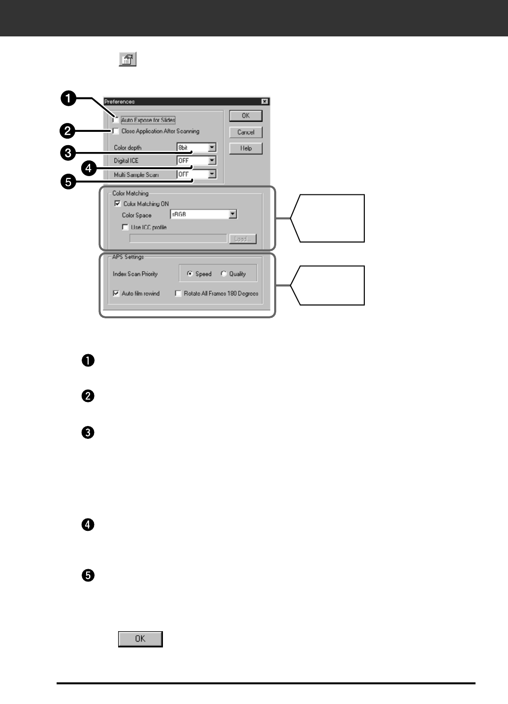
SETTING THE PREFERENCES
21
1. Click on .
Auto Expose for Slides checkbox
Close Driver software After Scanning checkbox
Digital ICE Setting box
2. Set the preferences as desired.
Select this checkbox when scanning underexposed slides.
Closes the scanner's driver software after the scan is complete.
Select the DIGITAL ICE (removing dust or scratch) from OFF and ON.
This function is not avaialble for monochrome film.
Color depth Setting box
The pixel depth of each color channel used to scan your image (RGB or CMY). Three
options are available:
• 8-bit – over 16.7 million colors
• 16-bit – over 2.8 billion colors
• 16-bit linear – same as 16 bit, but image correction is not applied when the image is
scanned.
3. Click on to accept the new preference settings.
• Changes to the Preference settings take effect immediately.
Multi-Sample Scanning Setting box
This function reduces the random noise by referring the average of the result while
scanning several times.
Select the times of scanning operation from OFF, 2 times, 4 times, 8 times and 16 times.
COLOR
MATCHING
Settings (See
page 66.)
APS Settings
(See page 57.)
The Preference Dialog Box — Name of parts
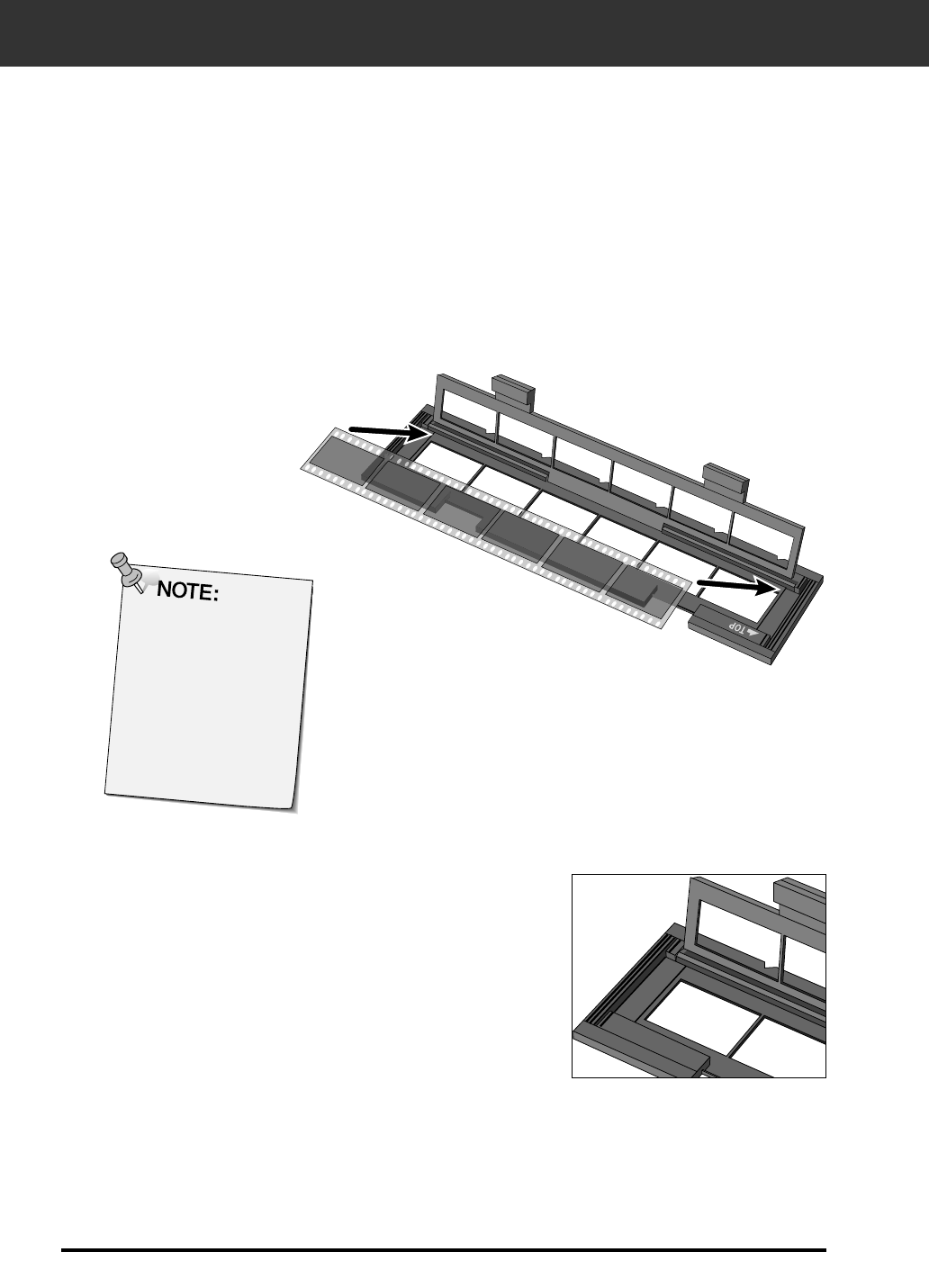
LOADING THE FILM HOLDER
22
2. Place the film in the film holder
emulsion side up.
• The film holder will accept film
strips up to 6 frames long.
• Brush dust off the film before
placing it into the film holder.
Using the included 35mm negative and slide holders, the Minolta Dimâge Scan Elite can scan
mounted or unmounted…
• 35mm colour negatives • 35mm colour slides
• 35mm black & white negatives • 35mm black & white positives
Advanced Photo System negatives and slides can also be scanned using the optional AD-10
APS Adapter. See page 57.
1. Open the film holder.
3. Align the frames within the scanning windows.
4. Snap the film holder closed.
Loading the Negative Holder
The frame numbers
and text are
backwards when the
film’s emulsion side
is up.
LOADING THE FILM HOLDER
23
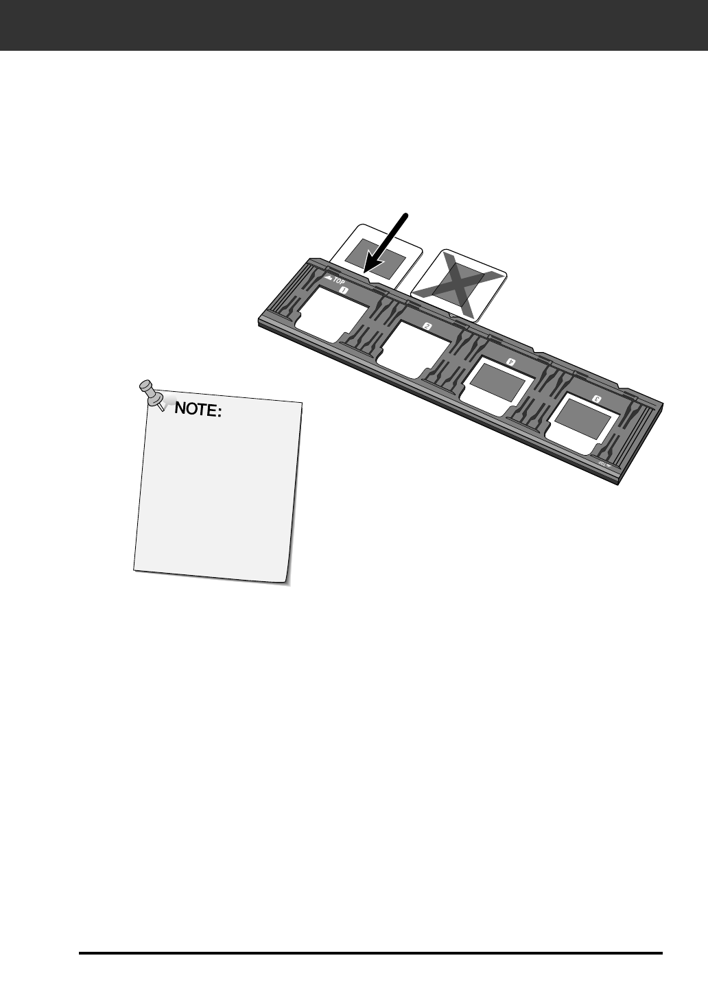
Loading the Slide Holder
Do not scan glass
mounted slides. Glass
mounts bend the light
from the line scanner,
producing bad results.
1. Insert slides into the slide holder emulsion side
up.
• Brush dust off the the slide before placing it into the film holder.
• Slide mounts must be thicker than 1 mm and thinner than 2 mm to fit
into the slide holder.
• Orient the slides horizontally, not vertically.
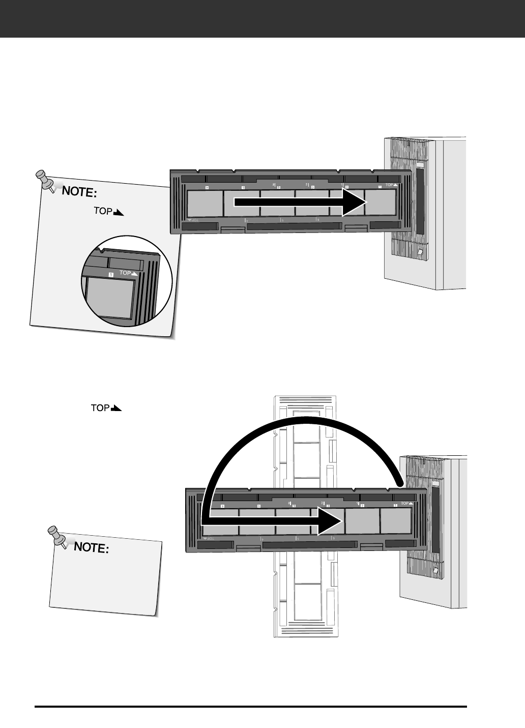
INSERTING THE FILM HOLDER INTO THE SCANNER
24
The white mark
should be upright.
The notches in the film and slide holders identify the position of the scanning windows. Push
the holder all the way in to scan the last frame on that side of the film holder. Remove, flip,
then re-insert the film holder to scan the frames on the other side of the holder.
Remove, flip, then re-insert the negative holder to
scan frames 4, 5, or 6.
• Frames 3 or 4 with the slide holder.
• The blue mark should be upright
Insert the negative holder into the scanner’s film
slot to scan frames 1, 2, or 3.
• Frames 1 or 2 with the slide holder.
Do not bend
negative holder
when inserting or
removing scanner.
25
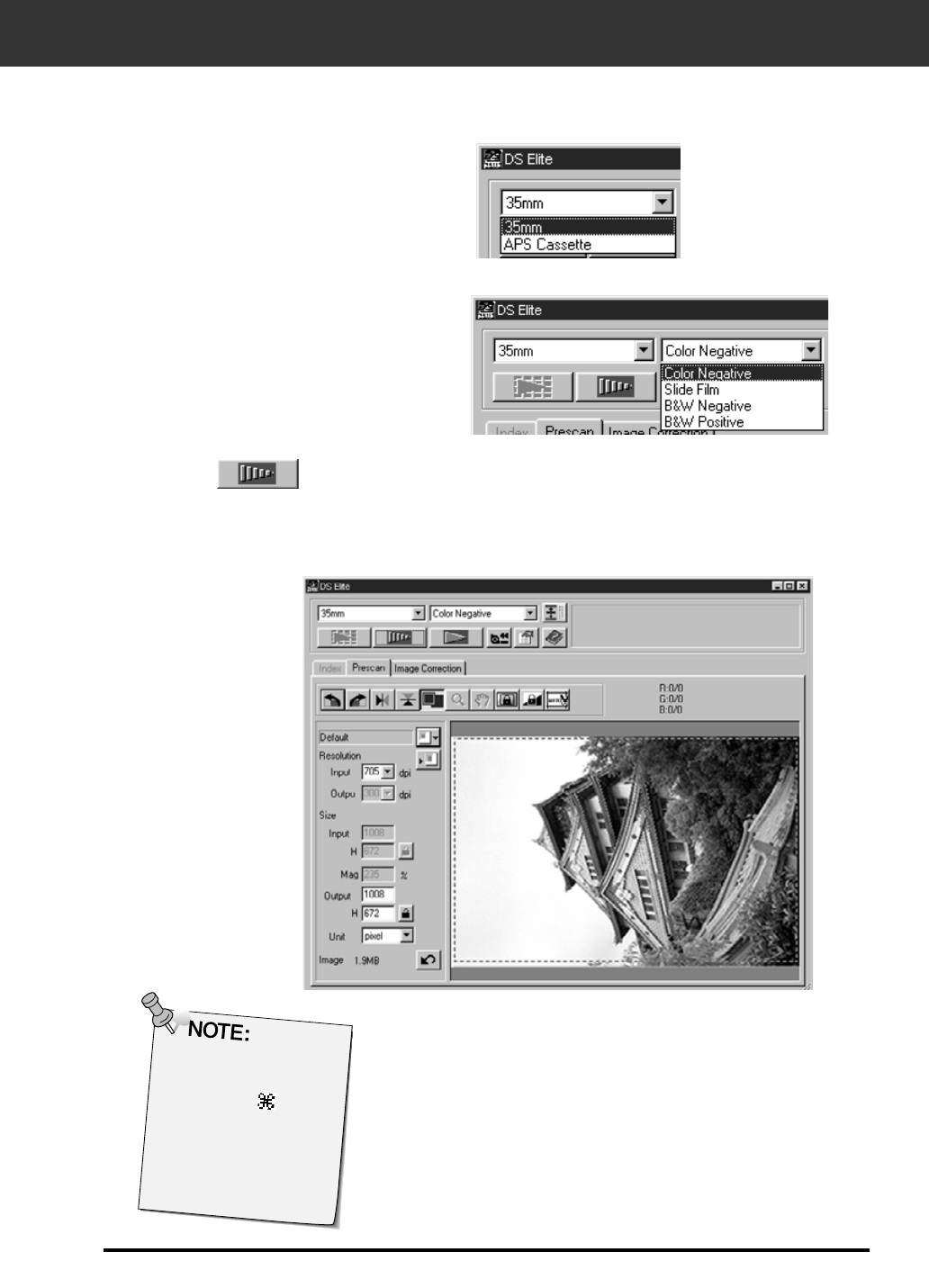
Setting the Film Type
1. Select 35mm from the film format
drop-down list.
• The Preview window appears.
2. Select the film type from the film
type drop-down list.
3. Click on in the Main window.
The previewed image will appear in the Preview window.
Press Ctrl when
previewing ( on the
Macintosh) to see
CMY values in the
RGB/CMY display.
PREVIEW—SETTING FILM TYPE
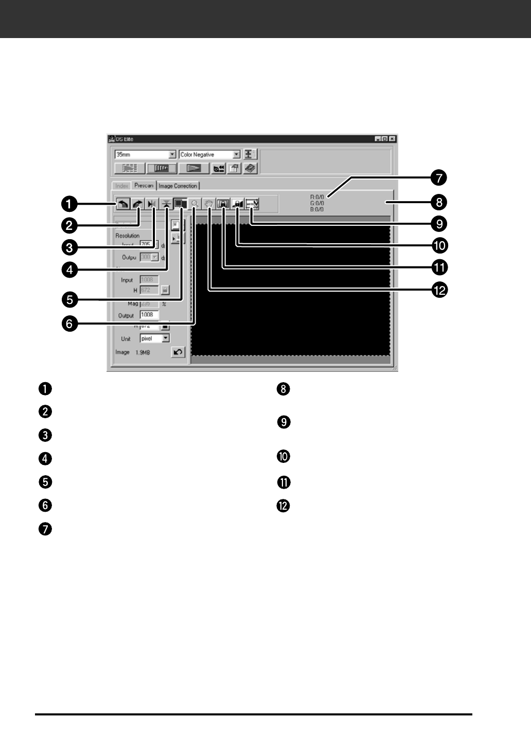
26
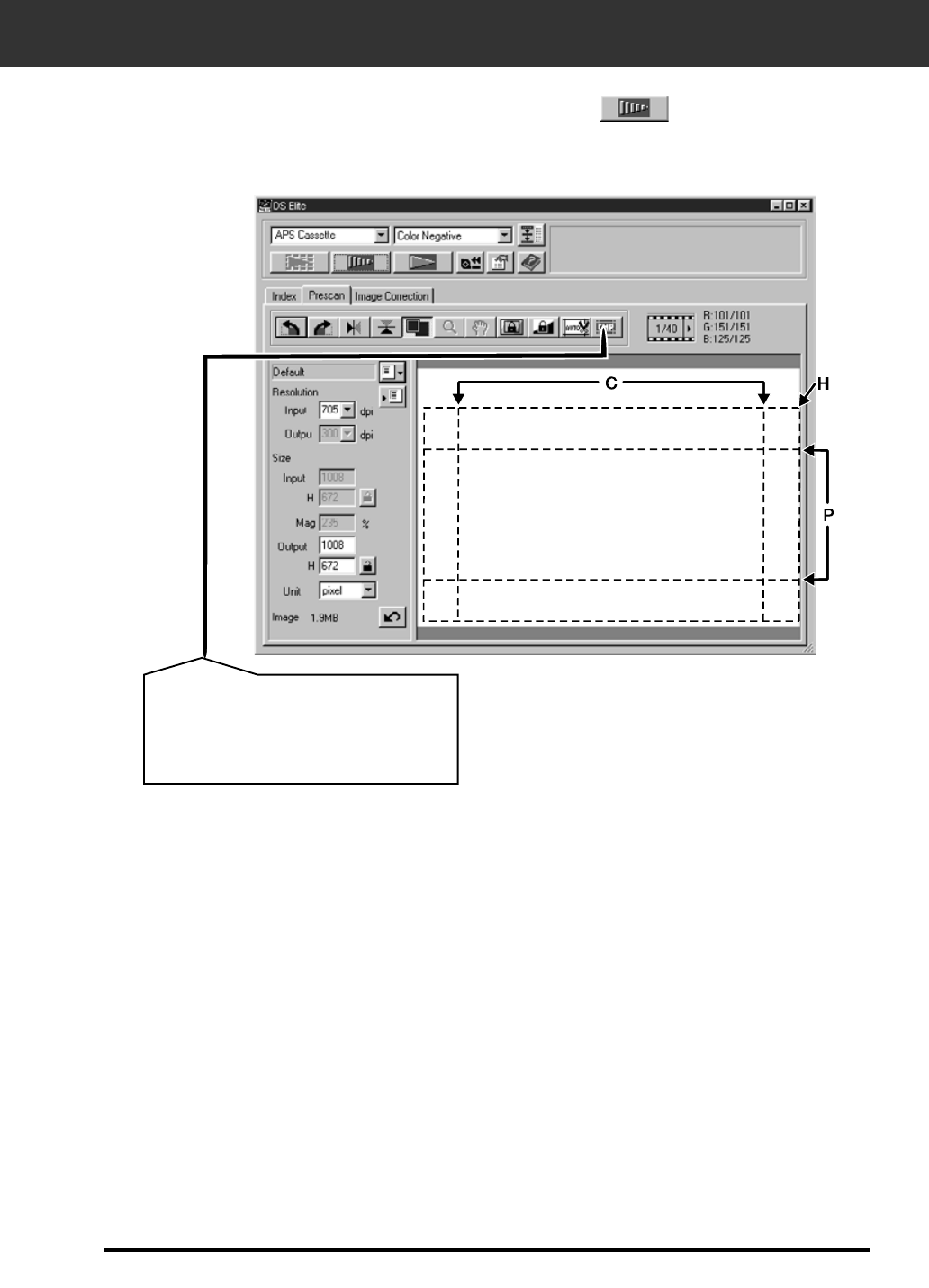
The Preview window part — Name of parts
Previewing creates a scan of the image that you can apply and view color, contrast, orientation,and
brightness corrections before clicking on the Scan button. This ensures that the final scan will be
the best it can be.
Rotate Left buttonZoom button Frame number indicator
Auto Holder/Mount Crop Adjustment button
AE Lock button
AE Area Lock button
Grab button
Rotate Right button
Flip Vertical button
Flip Horizontal button
Zoom button
Full-Screen View button
RGB/CMY displayFrame number indicator
27
AUTO-EXPOSURE LOCK
Especially useful when scanning bracketed exposures, AE (auto exposure) lock lets you scan
multiple images with the same initial exposure settings. AE Lock saves the automatic exposure
settings determined when an image is previewed. Subsequent images are previewed using the
‘locked’ exposure settings.
• AE-lock does not save exposure corrections made in the Variations, or Tone Curves/Histogram dialog boxes.
1. Click on .
• can not be selected until an image has been previewed.
After previewing the image…
Cancelling AE-Lock
1. Click on .
2. Click on to preview the image again.
2. Select another image, then click on .
• The scanner skips the setting exposure step in the preview sequence.
Setting AE-Lock
Images will be scanned using the AE lock settings until
AE lock is cancelled or the scanner is reinitialised.

28
AE AREA LOCK
The area used by the auto exposure algorithm can be adjusted so that only the selected area is
taken into account by AE.
Perform the procedure below after previewing the image.
2. Press the Shift key.
• The AE area is indicated by a line instead of the cropping area which is
indicated by a dashed line.
3. While pressing down the Shift key, change the AE
area.
• The operation is the same as that of changing the cropping area except
that the shift key should be kept pressed whilst clicking and dragging the
cursor.
• For details, see “Cropping” (P.30).
1. Click on .
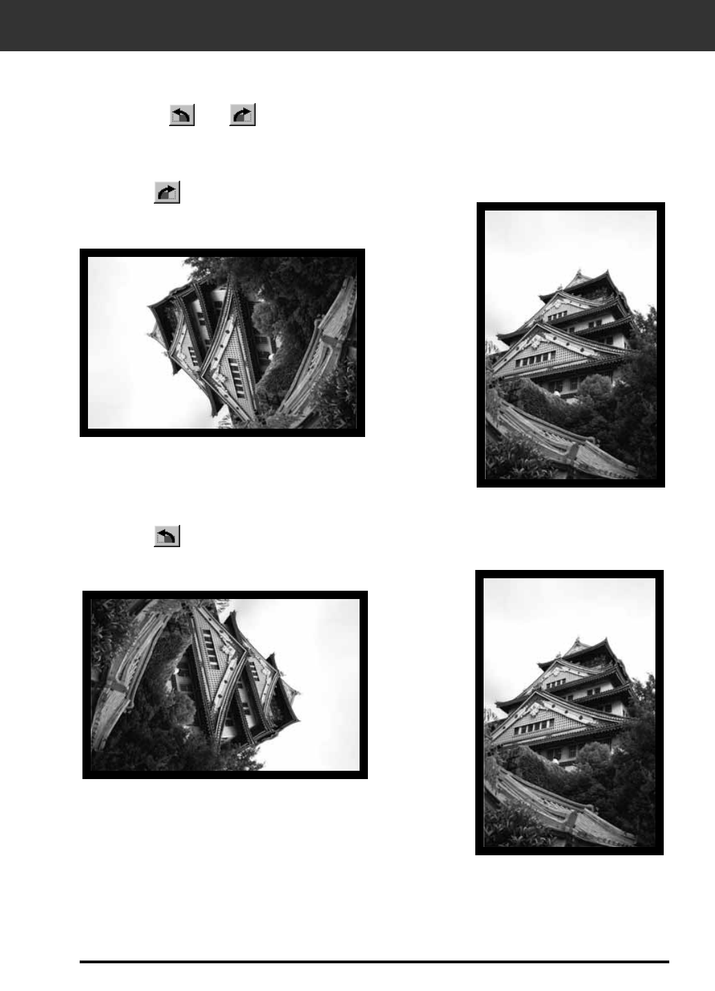
29
ORIENTING THE IMAGE
Click on the and buttons to correct the orientation of your image before scanning.
Changes will be reflected in the preview image.
Rotate
Click on to rotate
the image 90° clockwise.
Click on to rotate the
image 90° counter-clockwise.
30
ORIENTING THE IMAGE
The and buttons let you flip the image left to right or top to bottom before scanning.
Changes will be reflected in the preview image.
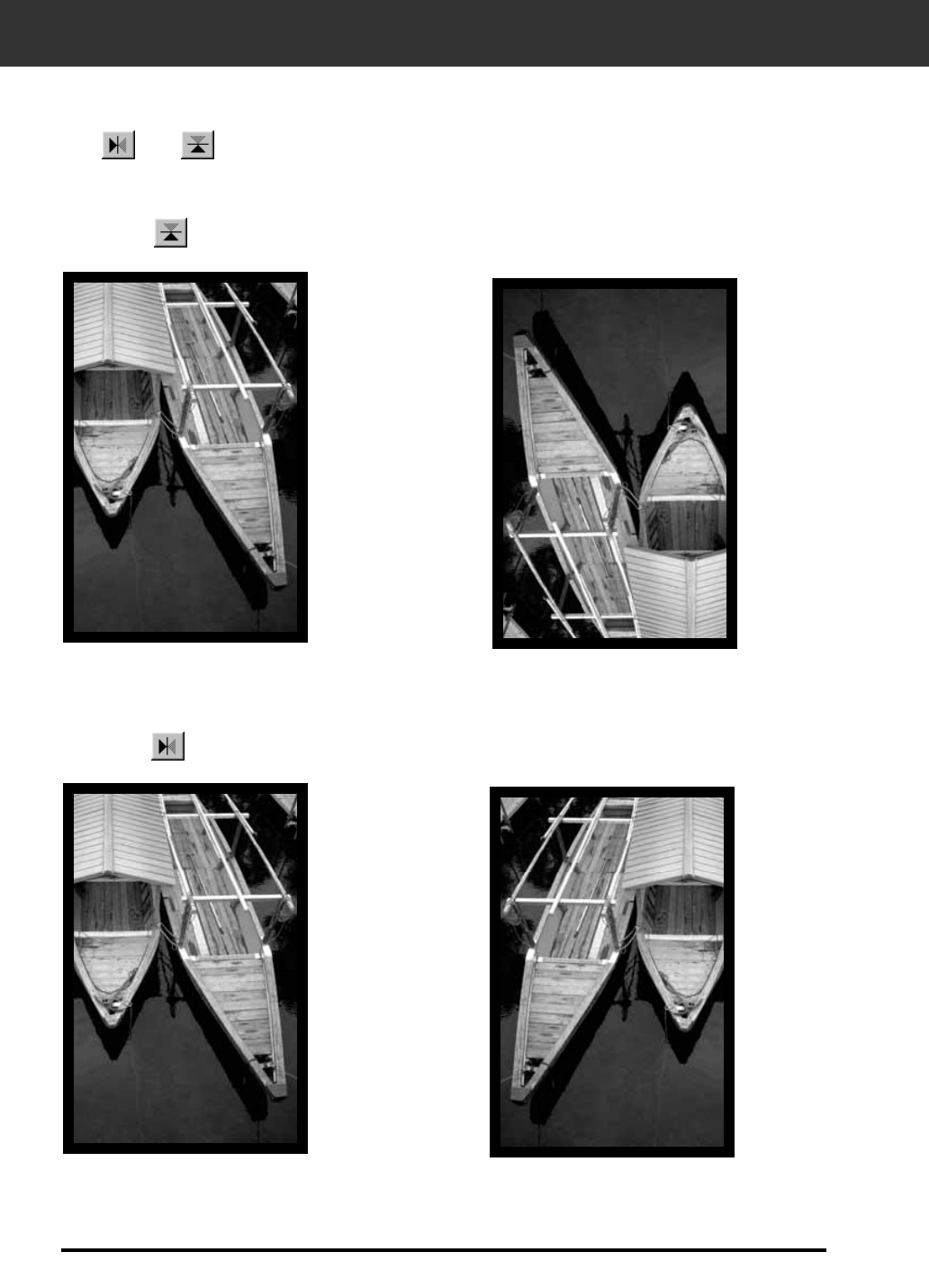
Flip
Click on to flip the image left-to-right.
Click on to flip the image top to bottom.
• The image is upside down compared
to the original scan.
• Image is backwards compared to
the original scan.
31
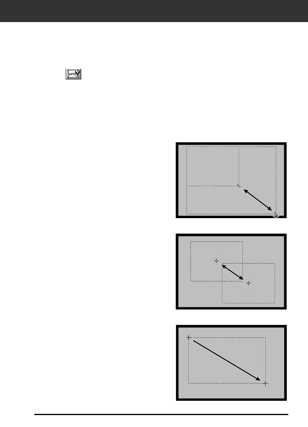
Click on the cropping frame and drag the
pointer in or out.
• Click on the corners and drag to resize the cropping
frame proportionally.
• Click on the sides and drag to resize the cropping frame
non-proportionally.
Click inside the cropping frame, then drag
the cropping frame to its new location.
The cropping frame defines how much of the preview image will be scanned. The dimensions
of the cropping frame are displayed in the lower left corner of the preview window.
Cropping
To enlarge or reduce the size of the cropping frame…
To move the cropping frame…
Click and drag outside the current
cropping frame.
To define a new cropping frame…
The cropping area is determined automatically so that the holder or slide mount frame in the
preview image is removed.
Auto Cropping
Click on .
32
ORIENTING THE IMAGE
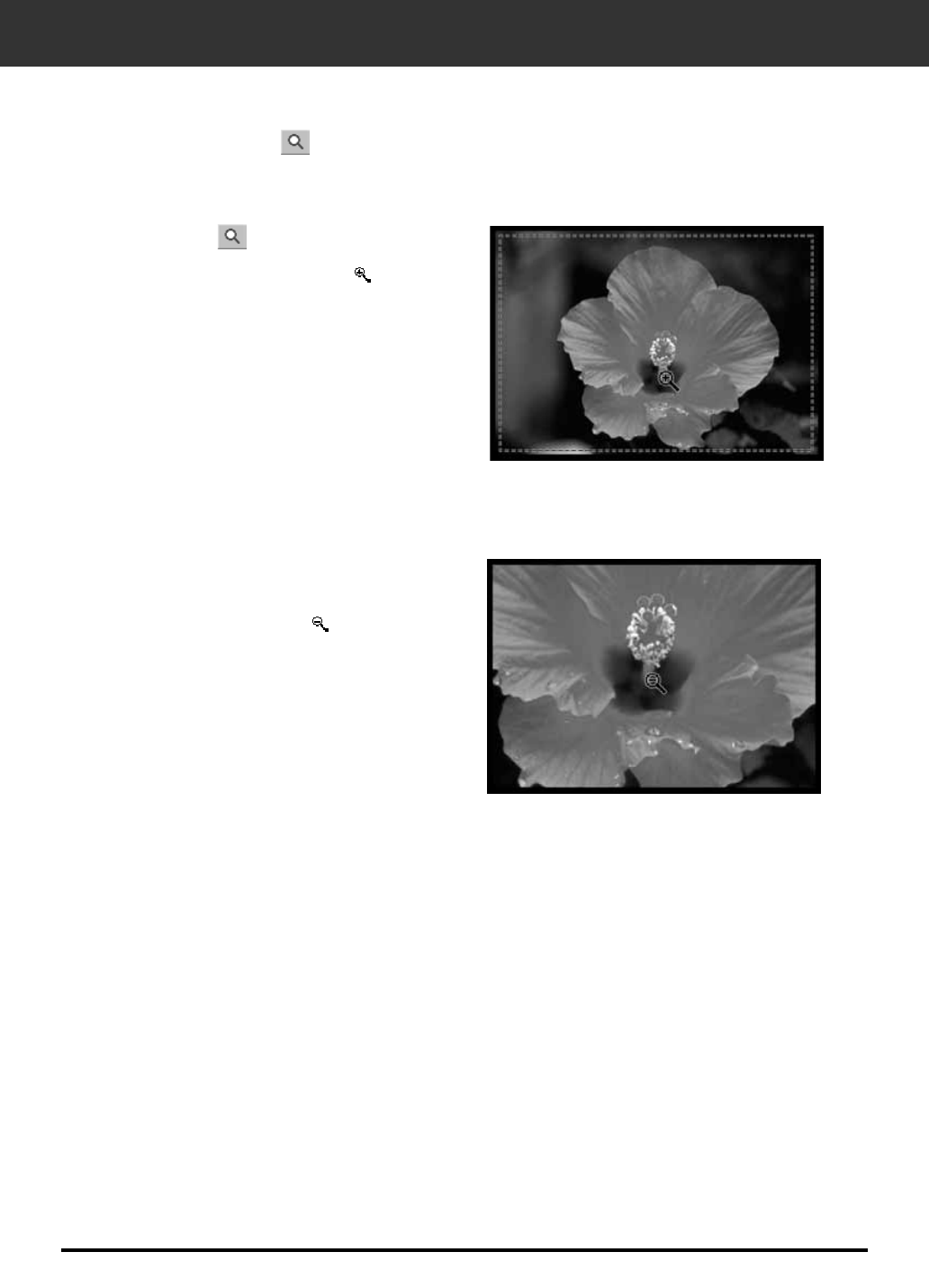
2. Click anywhere on the image to
zoom in.
• The clicked position will be the center of the
magnified view.
• The + disappears from the magnifier icon when the
maximum image magnification has been reached.
Use the zoom button to increase or reduce the image magnification.
Magnifying or Reducing the View
1. Click on in the Preview window.
• The pointer will change to .
1. Press and hold the Ctrl key (option
key on the Macintosh) to reduce the
image magnification.
• The pointer will change to .
2. Click anywhere on the image to
zoom out.
• The – disappears from the magnifier icon when the
minimum image magnification has been reached.
Zooming In
Zooming Out
This function allows you to display full preview image in the preview window.
1. Click the Full-screen view button in the Preview window.
Full screen view
33
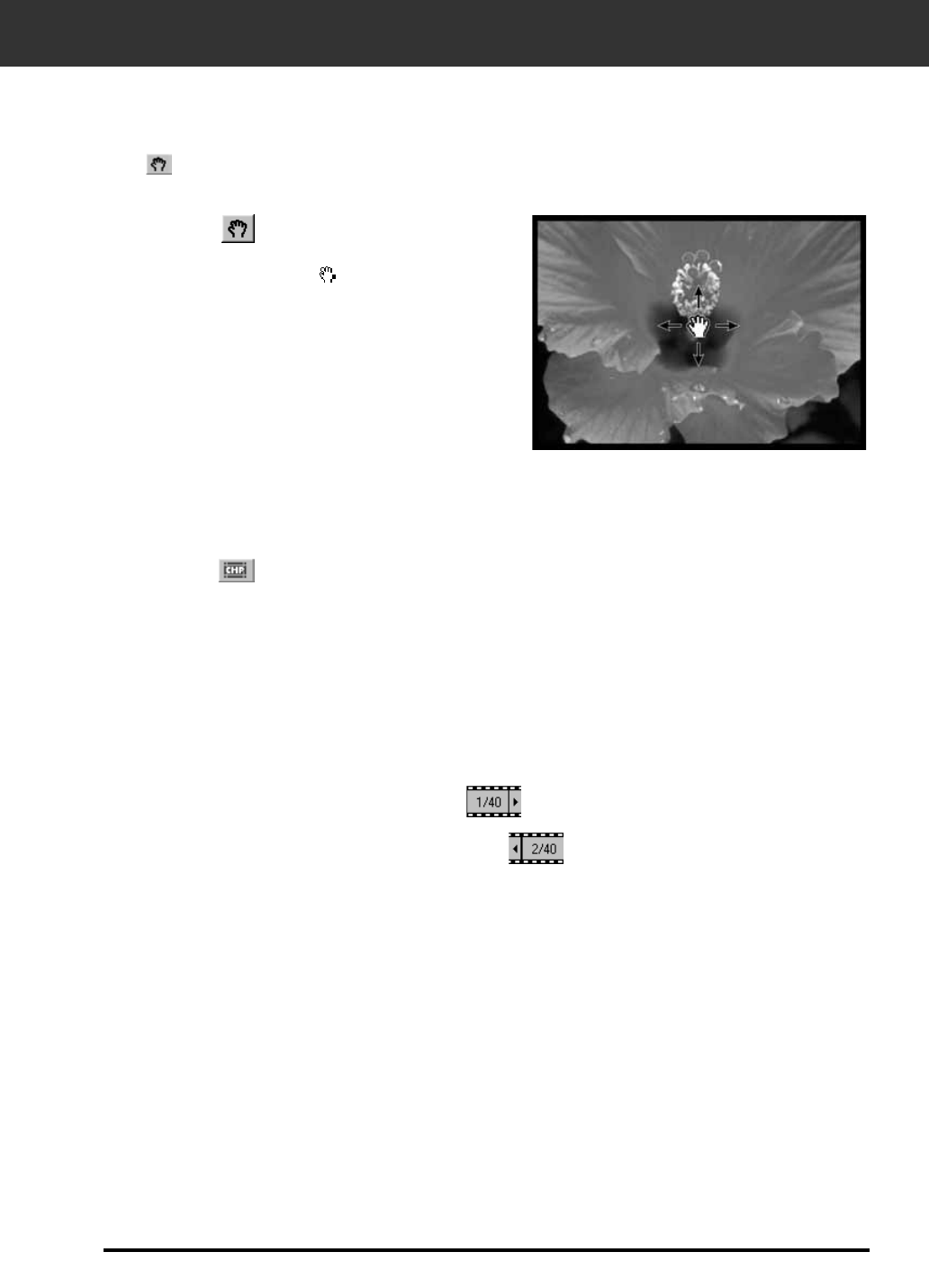
2. Click on and drag the image to the
desired location.
Use the grab button to scroll an enlarged image.
• can only be selected when the image has been magnified beyond the limits of the Preview window.
Scroll
1. Click on in the Preview image
display area.
• The pointer will change to .
ORIENTING THE IMAGE
When APS is selected in the Main Window, the CHP button allows you to quickly and easily define
the cropping frame by the standard APS format; C, H and P.
APS formats; C, H and P (APS only)
1. Click on to display the APS cropping frames.
• The cropping frames are displayed in sequence with each click of the CHP
button.
This function allows you to display the current frame number and the total number of frames of an
APS film.
Displaying Frame number (APS only)
1. To display the next frame, click on .
2. To display the previous frame, click on .
The RGB information from the pointer position is always displayed in the Preview window. The
information is described in brightness levels from 0 to 255. However, the display can be changed to
show CMY information.
RGB/CMY information
1. Press and hold the Shift key (command key on the
Macintosh) with the Preview window open.The RGB
information will change to CMY.
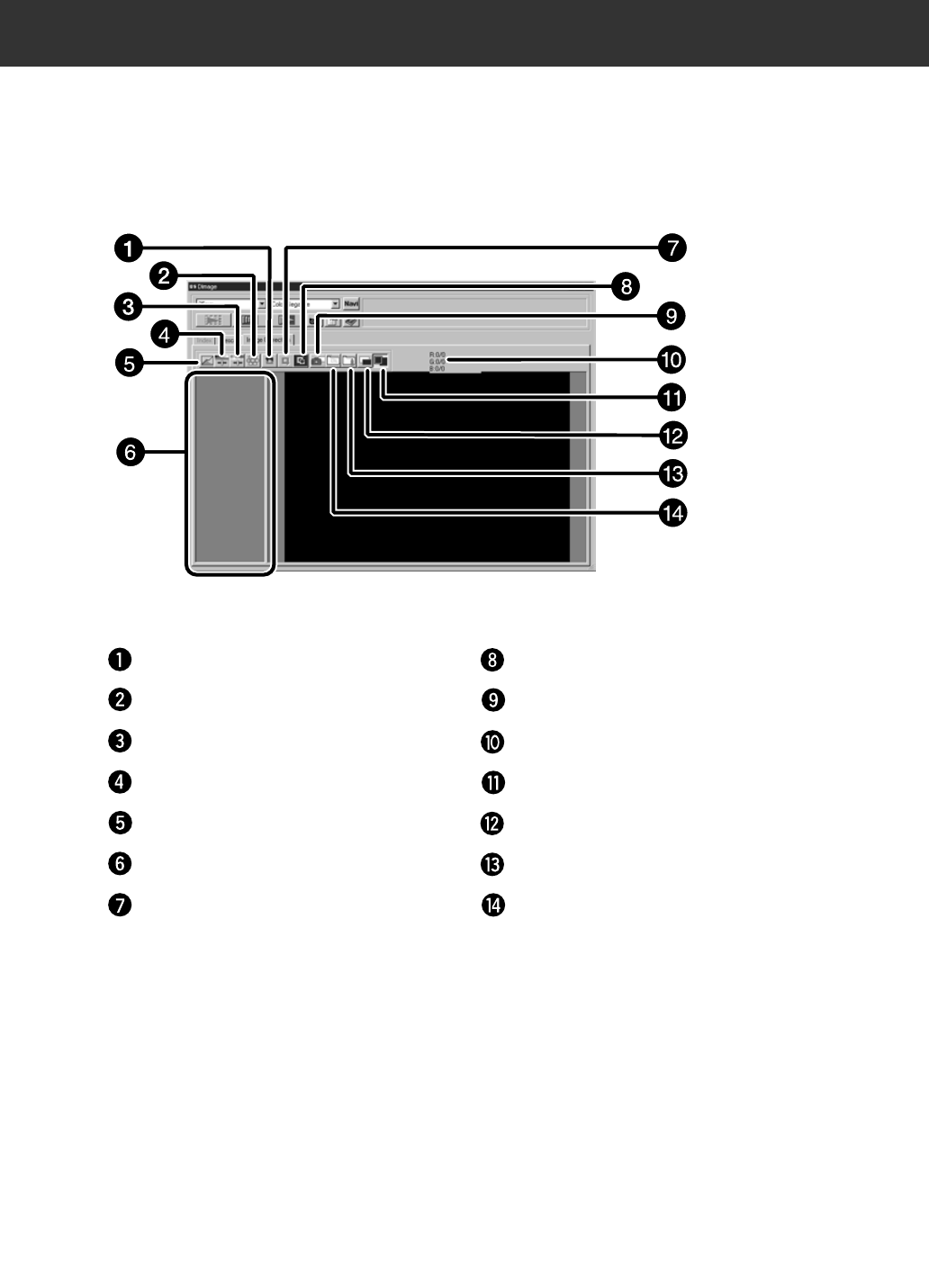
The Image correction window part — Name of parts
This scanner gives you three options for correcting the brightness, contrast, and color balance of
the final scan.
• Click on the Image Correction window in the Main window.
Undo button Correction Reset button
Snapshot button
RGB/CMY display
Image Correction Job Save button
Image Correction Job Load button
Pre/Post Correction Comparison Display
button
Full-Screen View button
34
Variations button
Hue/Saturation/Lightness Correction button
Brightness/Contrast/Color Balance Correction
button
Tone Curves/Histogram Correction button
Snapshot Display Area
Redo button
35
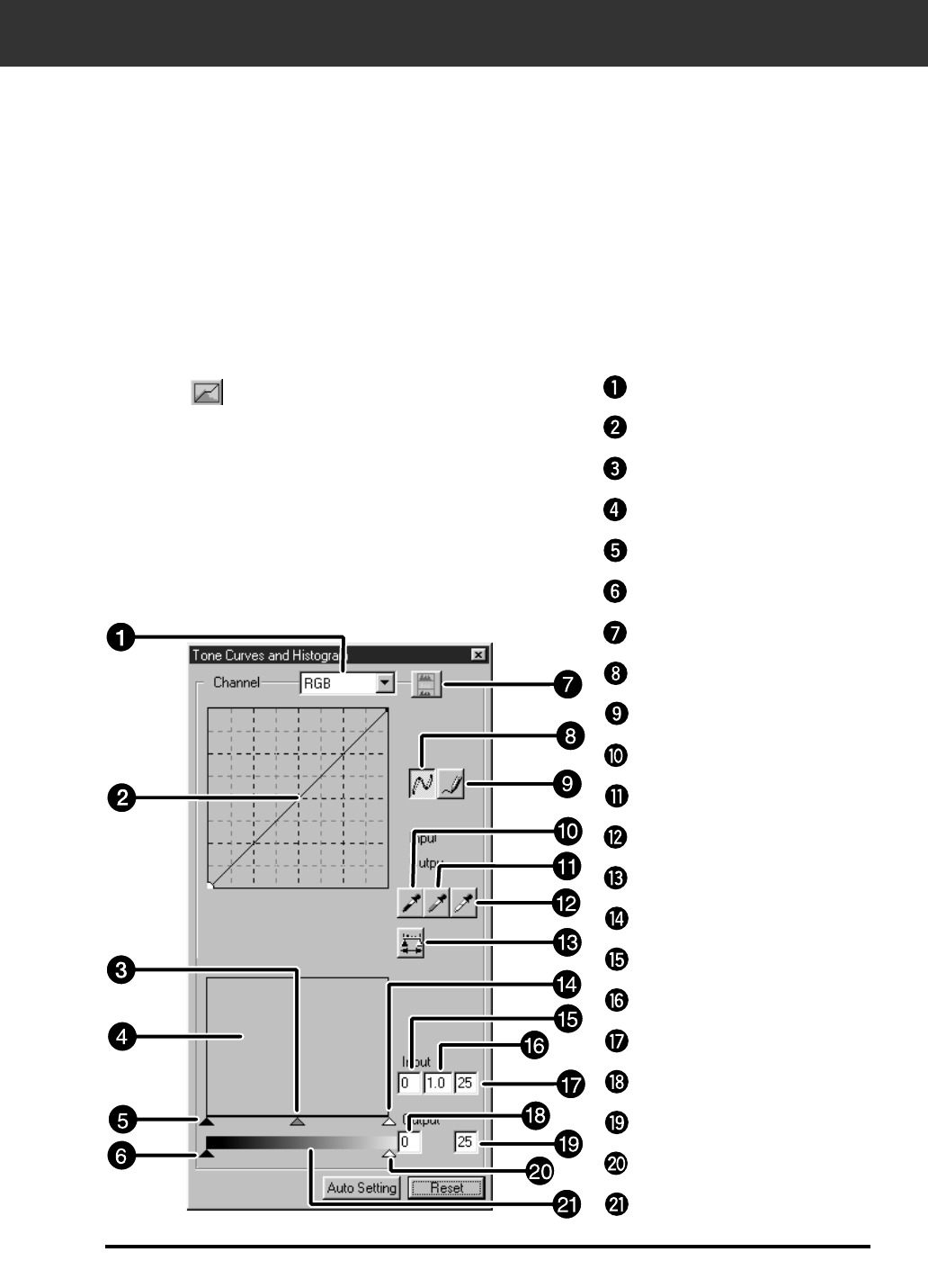
IMAGE CORRECTION – TONE CURVES/HISTOGRAM
Click on in the Image Correction window.
When the Tone curves/Histogram Correction button is clicked, the Tone Curves/Histogram
Correction dialog box is displayed.
The Tone Curves dialog box allows you to change the tone curves and to directly correct the output
value.
The Histogram dialog box allows you to specify the input and output area from the information
included in the scanned film and to then correct the image. This dialog box displays also the
histogram of the image area inside the cropping frame in each RGB color. The level is indicated in
256 color steps (0 to 255) from the left to right.
The tone curves and histogram are linked to each other so that when the tone curve is corrected,
the histogram is automatically corrected.
The Tone Curves/Histogram Dialog Box
— Names of Parts
Channel Selection list box
Tone curves/Smooth Curve button
Freehand curve button
Black point button
Gray point button
White point buttona
Apply button
Input Highlight slider
Input Shadow text box
Input Gamma text box
Input Highlight text box
Output Shadow text box
Output Highlight text box
Output Highlight slider
Gray scale
Tone curves
Input Gamma slider
Histogram
Intput Shadow slider
Output Shadow slider
Histogram RGB display button
The Tone Curves and Histogram Dialog Box — Names of Parts

36
IMAGE CORRECTION – TONE CURVES/HISTOGRAM
Changing the shape of a correction curve changes the output level for each corresponding input
level. Changing the shape of the red, green, or blue curves affects color balance of the image.
Changes to the RGB curve affect the image contrast and brightness.
1. Click on the arrow next to the channel selection
list to display the available channel (R, G, B,
RGB).
2. Select the channel of the color to be corrected.
3. Click and drag the portion of the curve to be
changed.
• The coordinate value of the cursor is displayed from 0 to 255.
• The corrected image by changing the tone curves is applied to the
preview image.
• You can also change the tone curves by freehand.
Correcting the Tone Curves
This function allows you to draw tone curves by freehand.
Changing Tone Curves by Freehand
1. Select the channel of the color (R, G, B, RGB) to
be corrected from the channel selection menu.
2. Click the Tone Curve Drawing button.
• The cursor changes to the pencil shape.
3. Draw the desired curve by dragging.
• To smooth out the curve points, click the Smooth Curve button.
• The change will be reflected in the preview image.
37
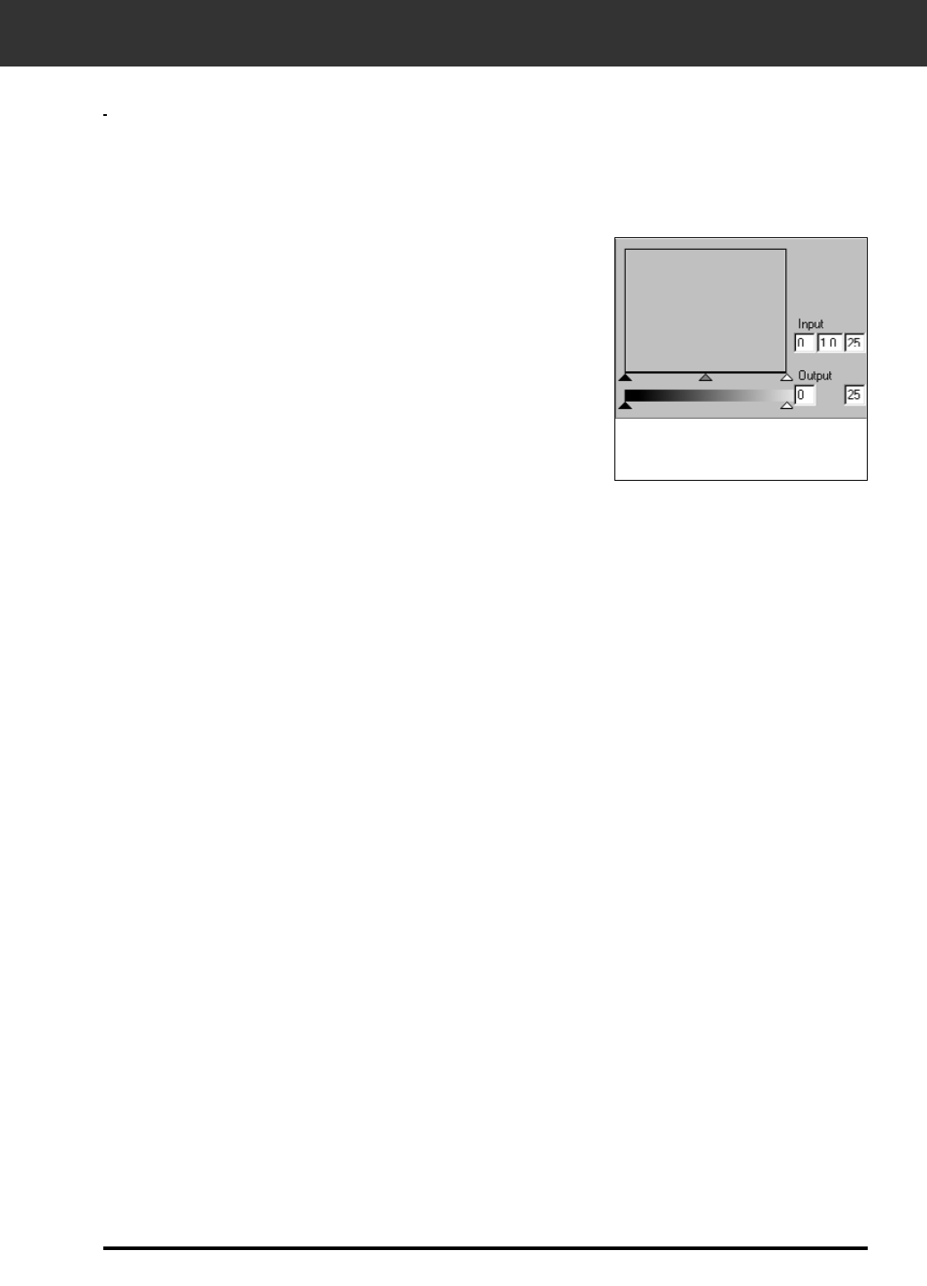
IMAGE CORRECTION – TONE CURVES/HISTOGRAM
Correcting the Histogram
1. Drag the slider to move it to the desired level or
input the value in the text box.
• The change will be reflected in the preview image.
Input Level Histograms
Displaying the Histogram of Each R, G, B color
1. Click the RGB Display button.
• When the RGB Display button is clicked again, the histogram of each R,
G, B channel disappears.
The input slide bar has the Input shadow slider, Input gamma slider and Input Highlight slider. The
output slide bar has the Output Highlight slider and Output shadow slider.
The image can be corrected by dragging the slider or inputting the value in the text box.
The change will reflect the prescan image.
Setting the White Point
38
IMAGE CORRECTION – TONE CURVES/HISTOGRAM
1. Double-click the Black Point
button.
• The Point Value dialog is displayed.
2. Input the desired black point value.
3. Click the Black Point button.
• The cursor changes to the black dropper shape.
4. Click the desired shadow point of
the image.
• The image is corrected so that the point you
clicked is the shadow point. The color of the shadow point is the black point value you input in step 2.
• The change will be reflected in the preview image.
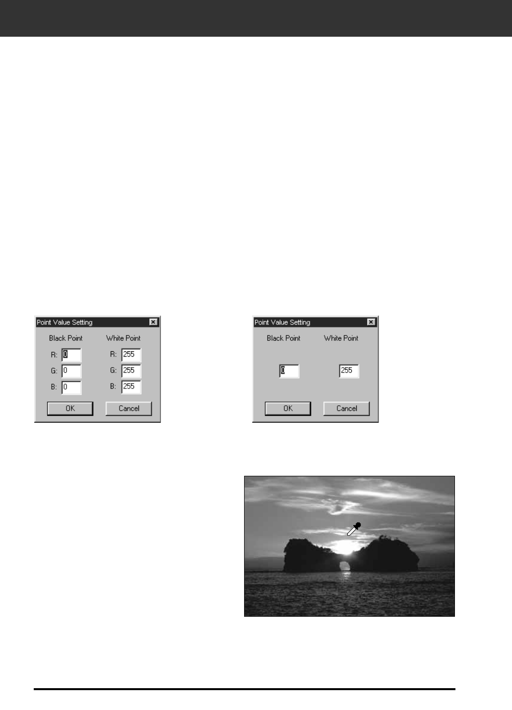
Setting the White or Black Points
This function allows you to correct the highlight or shadow point to the specified value.
• Changes are automatically applied to the preview image.
1. Double-click the White Point button.
• The Point Value dialog is displayed.
2. Input the desired white point value.
3. Click the White Point button.
• The cursor changes to the white dropper shape.
4. Click the desired highlight point of the image.
• The image is corrected so that the point you clicked is the highlight point. The color of the highlight point is the
white dropper value you input in step 2.
• The change will be reflected in the preview image.
Point Value Setting dialog box
When the film
type is set to
the color mode.
When the film
type is set to
the
monochrome
mode.
Setting the Black Point
39
IMAGE CORRECTION – TONE CURVES/HISTOGRAM
1. Click the Gray Point button.
• The cursor changes to the gray dropper shape.
2. Click the point to be changed to
gray in the image.
• The image is corrected so that the point you
clicked is the gray point.
• The change will be reflected in the preview image.
Setting the gray point
is not necessary for
most images.
Viewing the Histogram of Images After Making Corrections
When the Apply button is clicked, the histogram of images after making corrections can be
displayed.
The histogram after making corrections is displayed as long as you press this button. When the
button is released, the histogram returns to the previous one.
Setting the Gray Point
This function can specify the gray of images.
Auto setting
When the Auto setting button is clicked, the image is corrected automatically by removing no
information parts from the histogram and using all tone steps from 0 to 255.
40
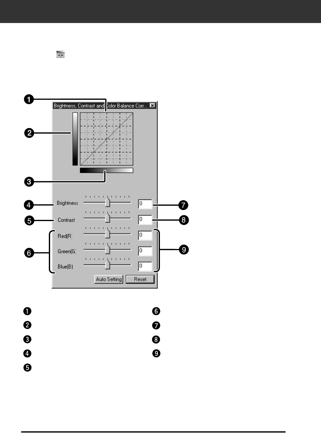
IMAGE CORRECTION — BRIGHTNESS/CONTRAST/COLOR BALANCE
When the Brightness/Contrast/Color Balance Correction button is clicked, the
Brightness/Contrast/Color Balance Correction window is displayed.
The images can be corrected by dragging the slider or inputting the desired value in the text box.
• Click on in the Image Correction window.
Post-Correction LUT
Contrast text box
Color Balance text box
Post-Correction Gray scale
Pre-Correction Gray scale
Brightness slider
Contrast slider
Color Balance slider
Brightness text box
The Brightness, Contrast and Color Balance Correction Dialog box — Name of
parts

41
1. Drag each Brightness, Contrast or Color balance
slider or input the desired value in the text box.
• The change will be reflected in the preview image.
• Moving the Brightness, Contrast or Color balance slider changes “Post-
Correction Gray Scale” and “Post-Correction LUT”.
Post-Correction LUT
The color of the image is changed as shown in the Post-
Correction LUT.
The correspondence between the color displayed on the Pre-
Correction Gray Scale and Post-Correction Gray Scale appears
on the Post-Correction LUT.
IMAGE CORRECTION — BRIGHTNESS/CONTRAST/COLOR BALANCE
Auto setting
When the Auto setting button is clicked, the brightness and
contrast of the image is corrected automatically according to the
lightness without changing the color balance.
42
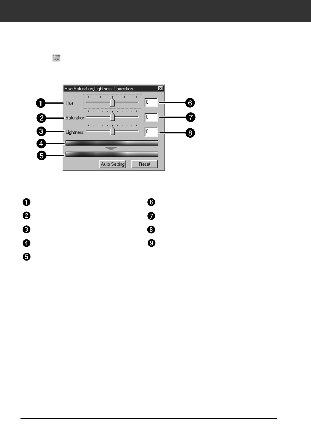
IMAGE CORRECTION — HUE/SATURATION/LIGHTNESS
When the Hue/Saturation/Lightness Correction button is clicked, the Hue/Saturation/Lightness
Correction window is displayed.
The images can be corrected by dragging the slider or inputting the desired value in the text box.
• Click on in the Image Correction window.
1. Drag the each Hue, Saturation or Lightness slider or input the desired value
in the text box.
• The change will be reflected in the preview image.
• To change the colour, move the Hue, Saturation or Lightness slider (or input the desired value in the text box).
• Moving the slider changes “Pre-Correction Color Sample” and “Post-Correction Color Sample”.
Pre-Correction Color Sample and Post-Correction Color Sample
The colour of the image is changed as shown in “Correction Color Sample”.
The colour displayed in “Pre-Correction Color Sample” is changed as shown in “Post-Correction
Color Sample”.
Hue-level slider
Saturation text box
Lightness text box
Saturation slider
Lightness slider
Pre-Correction Color Sample
Post-Correction Color Sample
Hue-level text box
Brightness text box
The Hue, Saturation, Lightness Correction Dialog box — Name of parts

43
Auto setting
When the Auto setting button is clicked, the saturation of the image is corrected automatically
without changing the hue and lightness.
IMAGE CORRECTION — HUE/SATURATION/LIGHTNESS
Reset
If you click the Reset button, the settings in the current correction window are reset.
44
Selecting the Correction Item
You can select from colour balance, brightness, contrast and saturation as the correction item to be
used in the variation correction. However, colour balance and saturation are not available when
using monochrome film.
1. Click on the arrow next to the correction item in the correction list box. The
available correction items are displayed.
2. Click the correction item.
• The variation frames are corrected according to the selected correction item.
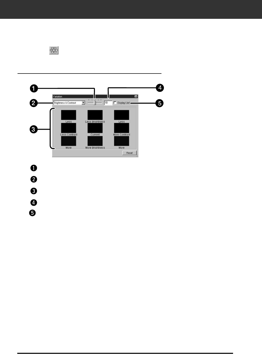
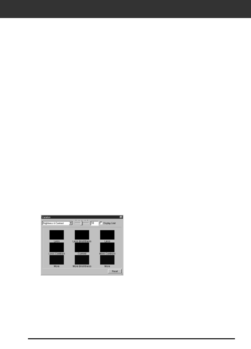
IMAGE CORRECTION – VARIATION CORRECTION
The Variations Dialog Box — Names of Parts
1. Click on in the Image Correction window.
The variation frames are displayed around the corrected preview image.You can correct the image
while comparing with the variation images.
Variation Amount Control slider
Correction list box
Pre/Post Correction Image Display Area
Variation Amount Control text box
Limit Indication check box
45
IMAGE CORRECTION — VARIATION CORRECTION
Color Balance Correction
The 6 images that have been corrected by one-step in each RGBCMY direction for the center
image are displayed.
1. Click the colour balance.
• The corrected 6 frames of variation images are displayed.
2. Click the image in the direction you want to correct from the 6 frames of the
variation images except for the center image.
• The image you clicked is placed in thw centre and 6 new variation images that have been corrected by one-step
in each direction are displayed.
3. Correct the image by repeating the operation in step 2.
The 8 images of which brightness and contrast have been corrected by one-step in horizontal and
vertical direction respectively for the center image are displayed.
The variation images on the left and lower sides of the center image show the – correction effect,
and on the right and upper sides of the center image show the + correction effect.
1. Click the image in the direction you want to correct from the 8 frames of the
variation images except for the center image.
• The image you clicked is placed in the centre and 8 new frames of the preview images that have been corrected
in each direction are displayed.
2. Correct the image by repeating the operation in step 1.
Brightness & Contrast Correction
46
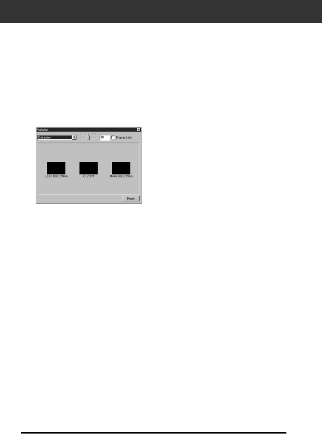
Saturation Correction
The 2 images of which saturation has been corrected on the right and left sides of the center image
are displayed . The variation image on the left side shows lower effect, and on the right side shows
higher effect.
1. Click the image in the direction you want to correct from the 2 frames of the
images except for the image in center.
• The image you clicked is placed in the centre and 2 new frames of the variation images that have been
corrected are displayed.
2. Correct the image by repeating the operation in
step 1.
IMAGE CORRECTION — VARIATION CORRECTION
Changing the Amount of Correction Step
The amount of correction step can be changed by moving the
Variation Amount Control slider. The desired amount can be also
input in the text box.
47
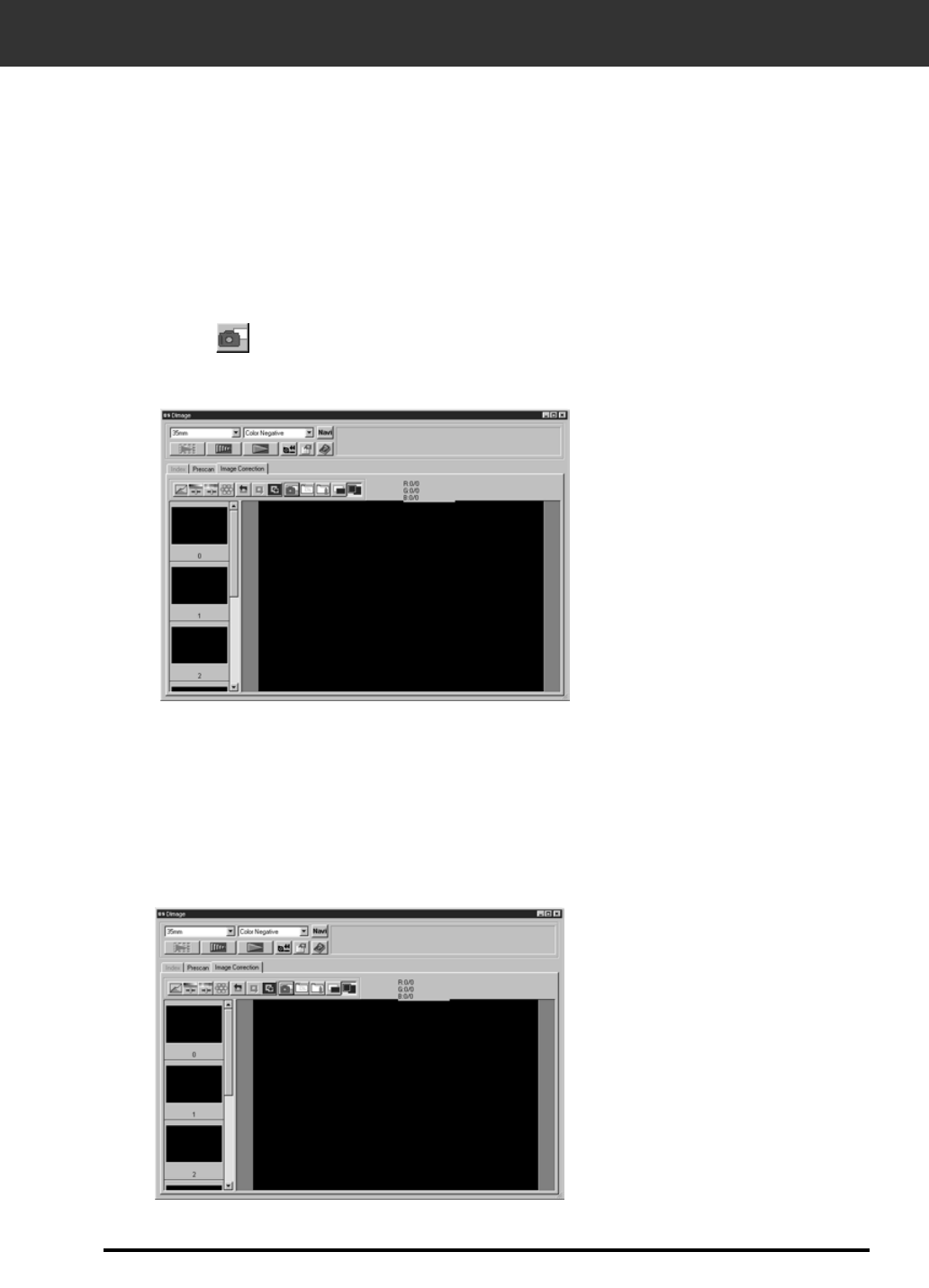
IMAGE CORRECTION — SNAPSHOT
When the Snapshot button is clicked, the current preview image is stored in the Snapshot Display
Area temporarily and displayed as a thumbnail.
When the thumbnail in the Snapshot Display Area is double-clicked, that image is displayed in the
preview window.
This allows a number of varying different corrections to be made and then compared without having
to go back and retrace previous correction steps.
Storing in the Snapshot Display Area temporarily
1. Click on .
• The displayed preview image is displayed in the Snapshot Display Area
as a temporary storing place.
Displaying the image stored temporarily as a preview image
1. Click on the thumbnail in the Snapshot Display
Area.
• The displayed preview image is deleted and the thumbnail image is
displayed as a preview image.
Snapshot Display Area 1
Snapshot Display Area 2

48
Full-Screen View
This function allows you to display full screen the view of the corrected image in the image
correction window.
1. Click the Full-Screen View button.
• When the Pre/Post Correction Image Comparing Display button is clicked, the size of the pre and post correction
image is automatically changed according to the size of the main window.
Checking the Correction Result While Lining Up Images
When the Pre/Post Correction Comparison Display button is clicked, the image correction
windows are divided into right and left sides and pre-correction images are displayed in the left
side, and post-correction images are displayed in the right side.
49
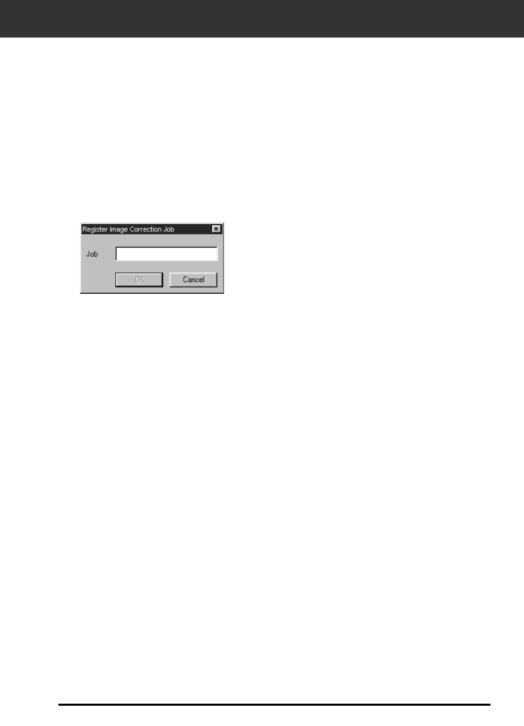
IMAGE CORRECTION — JOB SAVE/JOB LOAD
Saving Image Correction Job
2. Input the job name and click on the OK button.
• The current image correction setting is saved as an image correction job.
The image correction setting in each correction window can be
saved as an image correction job. You can easily correct the
image by loading the apporopriate correction job.
1. Click on the Image Correction Job Save button in
the Image correction tab.
• The Register Image Correction job dialog box is displayed.
50
IMAGE CORRECTION — JOB SAVE/JOB LOAD
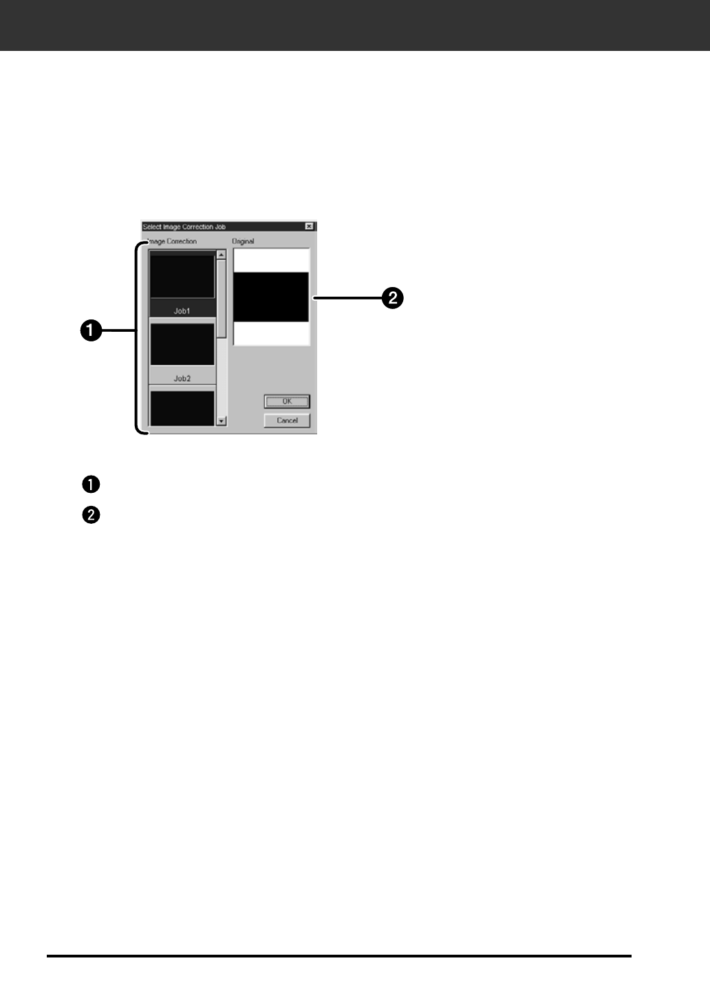
1. Click on the Image Correction Job Load button in
the correction window.
• The Image Correction Job List window is displayed.
Loading Image Correction Job
This function allows you to load the saved correction job and apply an image correction to the
displayed image.
2. Select the image correction job and click on the
OK button.
Image Correction job display area
Original image display
Canceling the Image Correction
When the Undo button is clicked, the current image correction is canceled and the image returns to
the previous one.
Redo the Correction
When the Redo button is clicked, the canceled image correction can be resumed.
Delete the Image Correction
When the Undo Correction button is clicked, all image correction is deleted and the image returns to
the initial state.
51
NAVIGATION
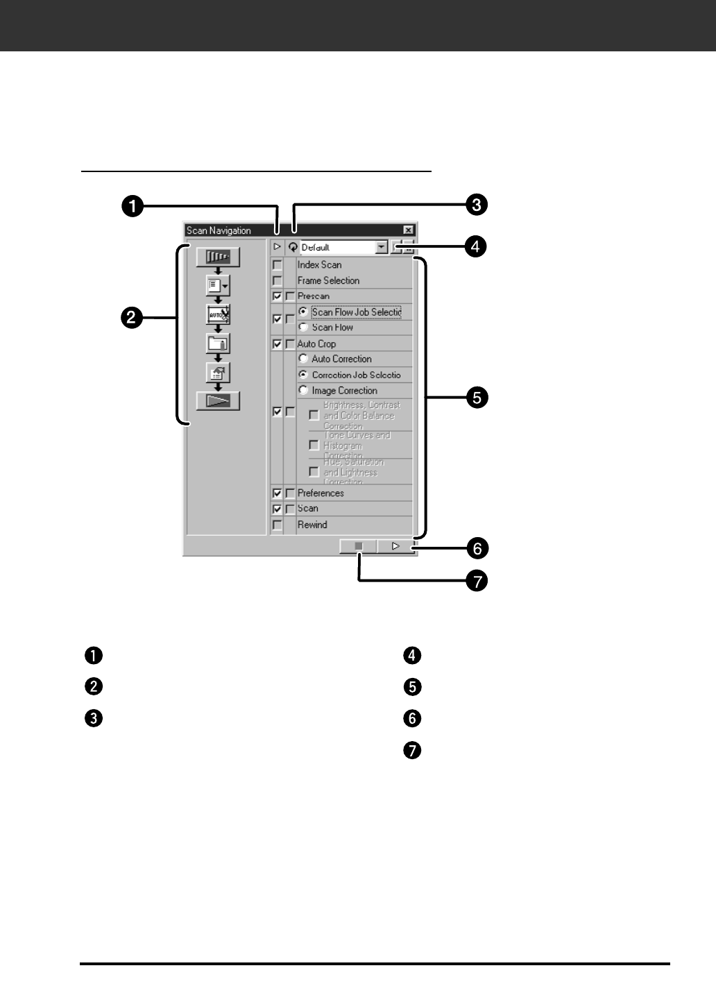
The Navigation window allows you to automat the procedure of scanning. When the Navigation
button is clicked in the Main window, the navigation window is displayed.
The Navigation Dialog box — Name of parts
Operation Item checkbox
Navigation Flow
APS Repeated Operation Item
checkbox
Navigation Menu list box
Operation Items
Navigation Start button
Navigation Stop button

52
NAVIGATION
Navigation Menu
This menu allows you to select the saved setting for automatic
operation. Not only the saved settings but the “Save Setting” and
“Delete Setting” items are displayed in this menu.
1. Select the operation items in the Operation Item
Checkbox or APS Repeated Operation Item
checkbox.
• The selected items are displayed with the buttons and arrows as a
Navigation Flow.
2. Click the Navigation Start button.
• To stop, click the Navigation Stop button.
Operation item checkbox
Insert the check mark in the operation items to be performed as
the automatic operation.
When using a film format other than APS, the index scan, film
frame selection and rewind cannot be selected.
1. Insert the check mark in the operation items to be
performed as the automatic operation.
APS repeated operation item checkbox
Insert the check mark in the items to be performed for all frames
of the images every time you execute the automatic operation.
When using a film format other than APS, the APS Repeated
Operation Item checkbox cannot be selected.
1. Insert the check mark in the operation items to be
performed for all frames of the images every time
you execute the automatic operation.
Operation items
The operation items in the automatic operation are displayed.
1. Select the details of the operation items with the
radio button or checkbox.

53
Saving, Selecting and Deleting a Navigation Setting
This function allows you to save the navigation settings.
The above settings can be saved, selected or deleted in the
Navigation Menu list box.
Saving a Navigation setting
1. Click on the arrow next to the Navigation menu
list to display the available menu.
2. Select saving setting.
• The Navigation set saving dialog box is displayed.
3. Input the setting name and click the OK button.
Selecting a Navigation setting
1. Click on the arrow next to the Navigation menu
list to display the available menu.
2. Select the setting to be used.
Deleting a Navigation setting
1. Click on the arrow next to the Navigation menu
list to display the available menu.
2. Select the setting to be deleted.
• The Navigation set deleting dialog box is displayed.
3. Select the setting to be deleted and click the
Delete button.
NAVIGATION
54
FINAL SCAN
Twain Driver Plug-in Software
Scan the film according to the Preview settings.
With the Dimâge Scan Elite utility software, you can save the final scan in one of the following file
formats.
JPEG TIFF
BMP (Windows only) PICT (Macintosh operating system only)
The 48 bit (16 bit each RGB) image file can be saved in the tiff format only.
With the Preview image displayed in the Preview window.
1. Click on in the Main window.
• The final scan will begin.
• When scanning is complete, the final scan will appear in the host application.
2. Save the image using the instructions for your host application.
Utility Software
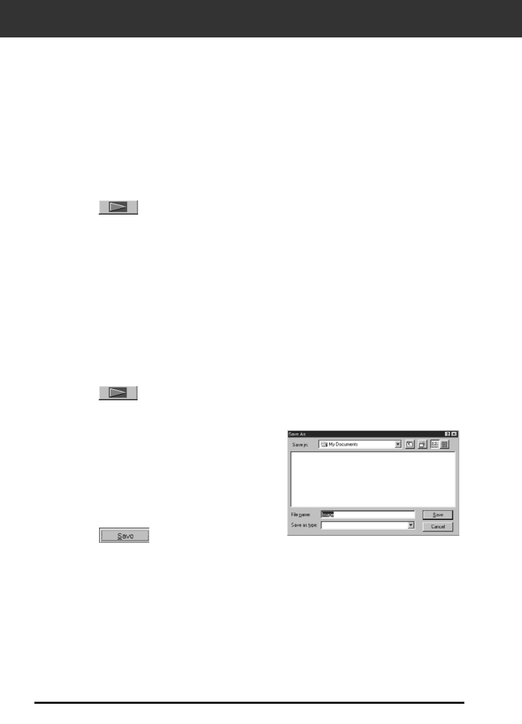
With the Prescan image displayed in the Preview window.
1. Click on in the Main window.
2. Enter the desired file name and select the
file destination.
3. Select the file type from the drop-down
list.
4. Click on .
• The final scan will begin.
• When scanning is complete, the scan will be saved in the selected
location. The software will return to the Preview window.
Your system’s standard save dialog box will appear.
3. Close the Control Window to exit the Dimâge Scan Elite driver software.
• The driver window will close automatically after each scan if the Close Driver After Scanning option was selected
in the Preferences dialog box (p. 21).
5. Close the Control Window to exit the Dimâge Scan
Elite driver software.
• The driver window will close automatically after each scan if the Close
Driver After Scanning option was selected in the Preferences dialog box
(p. 21).

SCANNING APS FILM
Set Preferences
Launch Software
Load and Insert the Film
Holder
Specify the Film Type
Prescan
Scan
Save
Index Scan
Select Frame(s) to
Prescan from Index
Print OR Select Frame(s) to
Prescan
Orient and Crop
Correct the Contrast,
Brightness and Color
SCAN FLOW
Specify the Job Type

56
LAUNCH SOFTWARE SPECIFY FILM TYPE
1. Launch the software (pp. 18-19).
2. Select APS Cassette from the film format drop-
down list in the main window.
3. Select the film type from the film type
drop-down list.
57
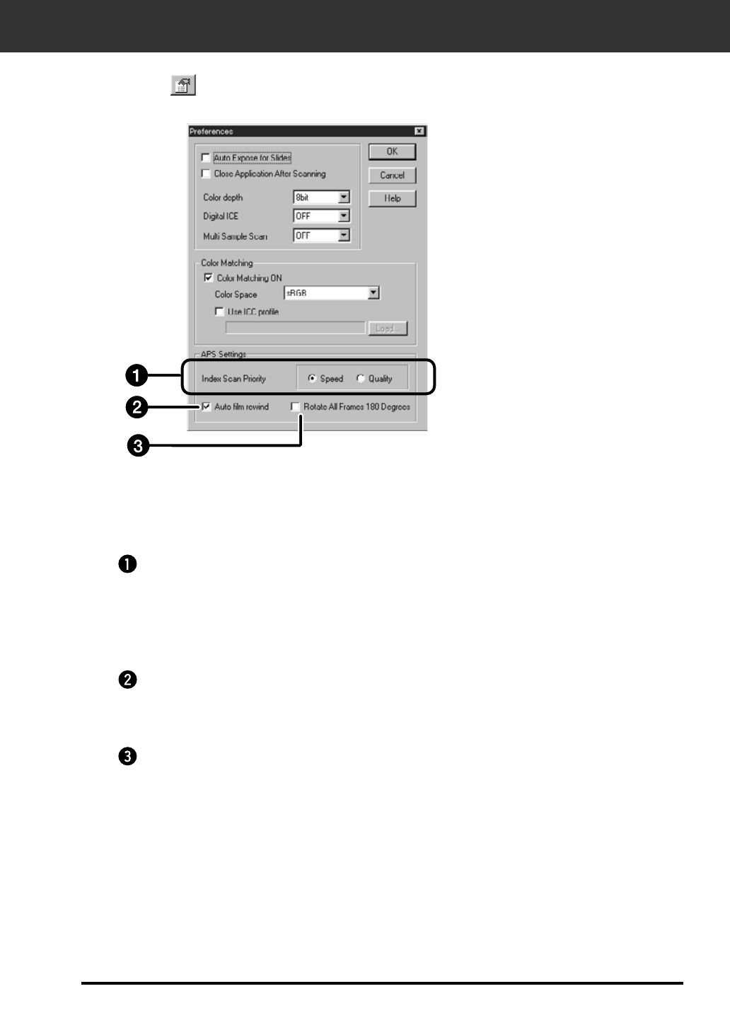
PREFERENCES – APS SETTINGS
Index Scan Priority
Speed – Creates a thumbnail representation of each frame on the roll.
Quality – Thumbnail and Preview images are created for each frame on the roll.
• Double-clicking on the index image opens the ready-made preview image.
Auto Film Rewind
Clicking on the eject button in the Command window automatically rewinds the film into
the APS cassette before the APS adapter is ejected.
Rotate All Frames 180°
Rotates all frames in the index window 180°.
1. Click on in the Main window.
The preferences dialog is displayed.
2. Set the Preferences as desired in the APS settings part.
• De-select the Close Driver Software After Scanning check box when scanning multiple images at the same time.
58
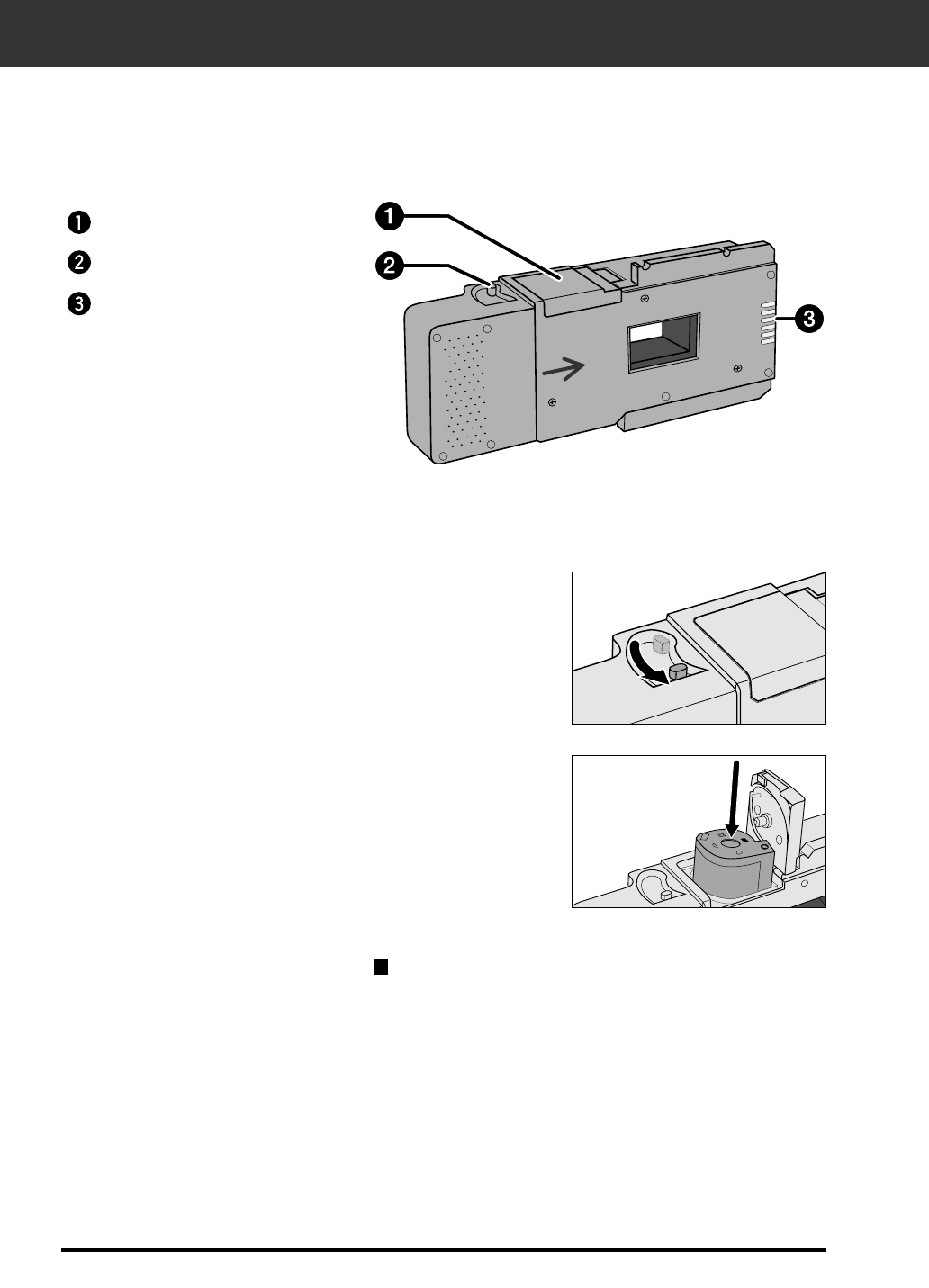
APS ADAPTER (OPTIONAL)
The AD-10 APS Adapter is an optional accessory. The Dimâge Scan Elite can not scan
Advanced Photo System film (IX-240 type) without the AD-10 APS Adapter.
Names of Parts
Loading the APS Adapter
1. Slide the film-chamber release as shown.
• The film-chamber door will open.
2. Insert the film cassette into the film chamber
with the VEI (Visual Exposure Indicator) on top.
3. Close the film-chamber door.
• The film-chamber door will not close if the mark is not highlighted.
Forcing the door shut could damage the cassette.
Film-chamber door
Film-chamber release
Scanner contacts*
* Do not touch
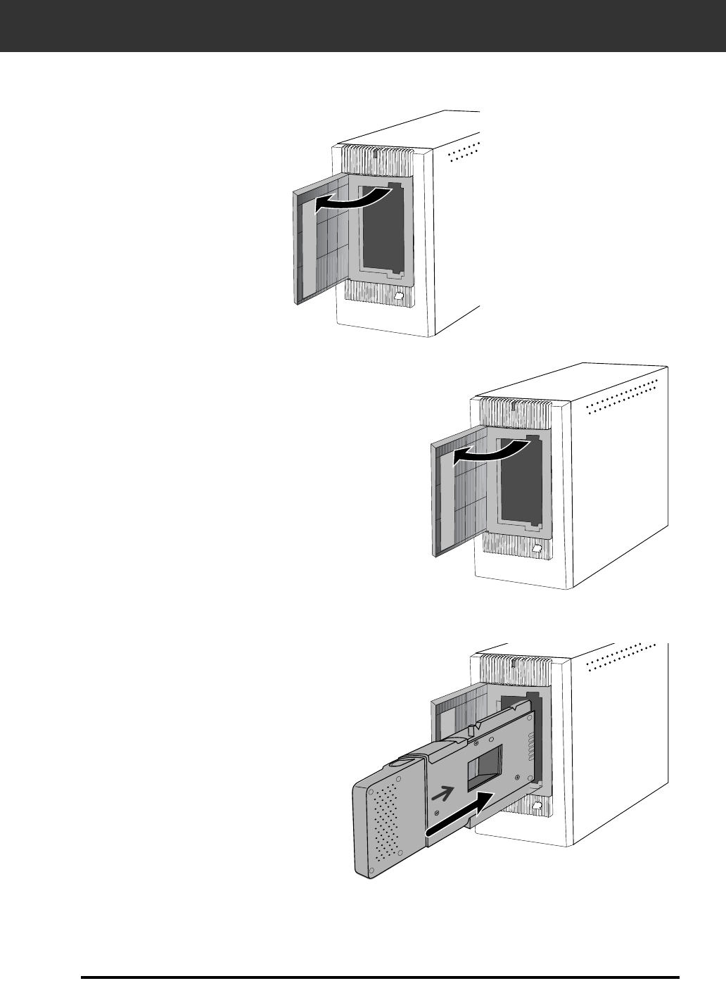
APS ADAPTER (OPTIONAL)
59
…then open the scanner’s film door.
1. Press the door where
shown to unlock,
2. Insert the APS Adapter into the scanner.
Inserting the APS Adapter
Index scan displays a scan of each image on the cassette in the index scan window. The time
required for an index scan depends on the performance of your machine.
If you don’t want to index scan the entire roll, select the frame number of the image you want
to scan from the index print provided by your photofinisher. Click on the appropriate image box
in the index window to select an image for prescanning or scanning.
• There are two options for making an index scan, Speed or Quality. Select the desired option in the Preference
dialog box (p. 57).
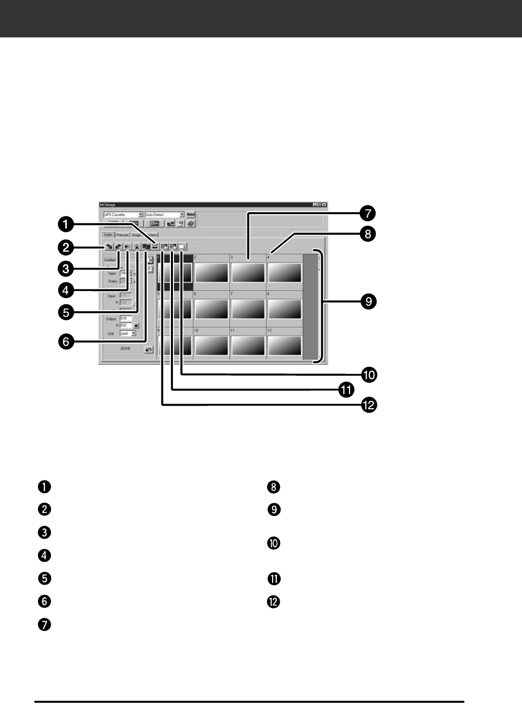
INDEX SCAN
60
Index Window – Names of Parts
Reverse frame order button Frame number
Index Image frame
Image Correction Job Load button
Index Load button
Save Index Scan button
Rotate left button
Rotate right button
Flip Horizontal button
Flip Vertical button
Full-Screen View button
Index imag
61
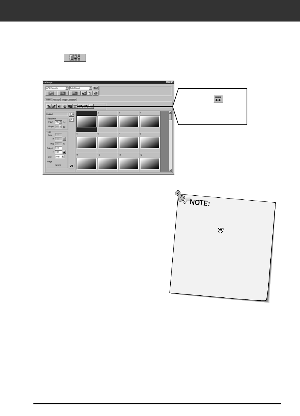
INDEX SCAN
Click on in the Main window.
• All frames on the cassette will be scanned and appear in the Index
window.
• To cancel the index scan, press the
escape key ( -• Command and
period for the Macintosh) until the
Cancelling Index Scan message box
appears.
• The completed index scans will
appear in the index window.
• Frames that have not been index
scanned can still be selected for
prescanning and scanning.
Click on to
reverse the
display order.
Index scan

62
INDEX SCAN
Index scan
Change the size of the Index scan window as desired. The position of the frames will change
accordingly.
Click on the corner tab and drag to reach the
desired size.
• When the Full-Screen View button is not clicked, the size and shape of
the index frames does not change.
• When the Full-Screen View button is clicked, the size of the index frames
changes automatically and all frames are displayed.
Select the desired frames, then click on , or , .
• The selected frames will rotate in 90° increments
either clockwise or counter-clockwise or flip vertically or horizontally.
• Rotating the index frame will not affect the Preview or Scan.
Rotating the Index Frames
Rotate index frames so they appear in the index scan window with the proper orientation.
63
PREVIEW AND IMAGE CORRECTION
1. Click on an image or an image box, then click on . The image will be
prescanned, then opened in the Preview window.
5. Close the Preview window to return to the Index
window.
• Adjustments made in the Preview window are held until the image is
scanned or the driver software is closed.
3. Apply contrast, brightness, and colour corrections
(pp. 34-46).
2. Orient and crop the image as desired (pp. 29-33).
4. Select the desired job type (pp.71-72).
• Only one job type can be selected when multiple images are scanned at
the same time.
Click here to specify an
APS format (C, H, or P)
cropping frame.
64
SCANNING THE IMAGE
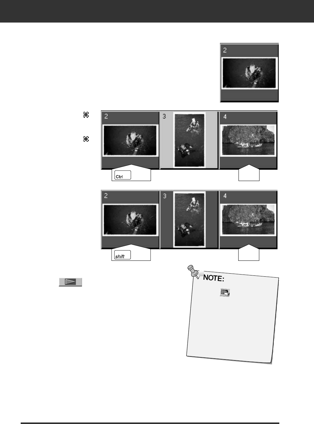
Selecting Frames
1. Click on an image to select it for scanning.
• Selected images are surrounded by a dark gray frame.
2. Click on to scan the selected
image(s).
• The scan is cancelled if more than the number of frames selected
is greater than the Max # of Frames set in the Preferences dialog
box. See Preferences - APS Settings on page 57.
• The image will be opened in your photo application software when
the scanner’s driver software is closed.
• Some photo applications can only acquire one image at a time.
• Press the shift key while
clicking to select all the
frames between the current
frame and the last frame
selected.
• Press the control key (
key for the Macintosh) while
clicking to select additional
frames for scanning.
• Press the control key (
key for the Macintosh) while
clicking to deselect an image.
CLICK CLICK
CLICK CLICK
Click on to save the
index as an image file.
• The image can be saved in
JPEG or BMP format
(JPEG or PICT format for the
Macintosh).
3. Refer to page 54 to save the scanned image(s).
• Multiple scans will be saved using the selected file name and numbered
chronologically. Example: File_Name01, File_Name02, File_Name03...
65
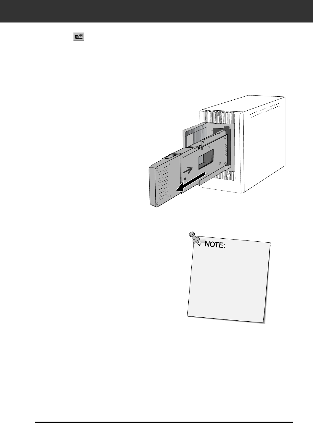
REMOVING THE APS ADAPTER
1. Click on to rewind the film into the cassette.
• This step is not necessary when the auto rewind option is selected in
the Preference dialog box window (p. 49).
3. Close the Control Window to exit the
Dimâge Scan Elite driver software.
• The driver window will close automatically after each scan if
the Close Application After Scanning option was selected in
the Preferences dialog box (p.21).
2. Remove the APS adapter from the scanner and
close the film door.
4. Open the APS adapter’s film chamber
door and remove the cassette.
Multiple images can be
scanned before closing the
software.
• Some photo applications
can only acquire one
image at a time.

66

APPENDIX
68
COLOR MATCHING
This function allows you to match the scanner data to the monitor type (colour space).
The output colour space and ICC profile can be specified by using the colour matching function.
To match the scanner data to the colour space, specify the output colour space.
To correct the color reproduction character of the monitor and to reduce the difference of color
between monitors in different environments in addition to the color space setting, specify the
monitor ICC profile settings in both the driver software and a software such as Photoshop. For
details, refer to page 69.
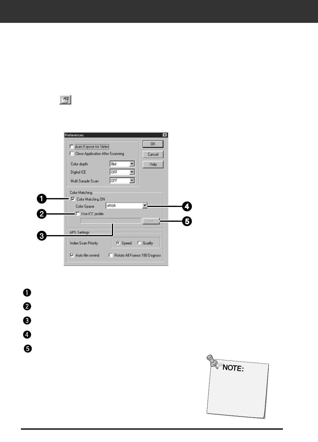
1. Click on in the Main window.
2. Set the preferences as desired.
• De-select the Close Driver After Scanning check box when scanning
multiple images at the same time.
The Color Matching in the Preference Dialog Box — Name of parts
Color Matching ON checkbox
ICC profile setting checkbox
ICC profile text box
Output Color Space list box
ICC profile Load button
When the color
matching function
is used, the
processing time
may be longer.

COLOR MATCHING
69
Output colour space setting
1. Insert the check mark in the “Color Matching ON”
box.
1. Insert the check mark in the “use ICC profile” box.
2. Click the Load button.
• The standard file open dialog of your operating system is displayed.
3. Select the ICC profile according to the monitor
being used.
The application may perform the original matching process. If you want to change the setting,
refer to the following sample settings.
When the colour matching function is used, the colour matching function of the OS, video card,
etc. are disabled.
When using Photoshop Ver.3.0.5 or Ver. 4.0.1
Output colour space: Apple RGB
ICC profile*1): select (for Windows)
This is not used (for Macintosh)
When using an application of which the monitor colour matching function is set to
ON Output colour space*2): option
ICC profile*1): select
When using an application of which the monitor colour matching function is set to
OFF, or when using an application which does not have the monitor colour
matching function.
Output colour space: do not specify
ICC profile*1): select
When an image is scanned with this setting, the data is matched according to the monitor
being used.
*1) ICC profile specifies the ICC profile of the monitor.
*2) The same color space as specified in the application is specified.
2. Click the (menu) button in the output colour
space list box, the available output colour space
settings are displayed.
3. Click the desired output colour space setting.
ICC profile setting
70
SCAN SETTINGS
The scan settings determine your final image’s resolution, dimensions, and file size, as well as
helping determine the image quality. You can select a Job (p. 71) to have the scan settings selected
for you or you can directly enter them into the Main window (Index window or Preview window).
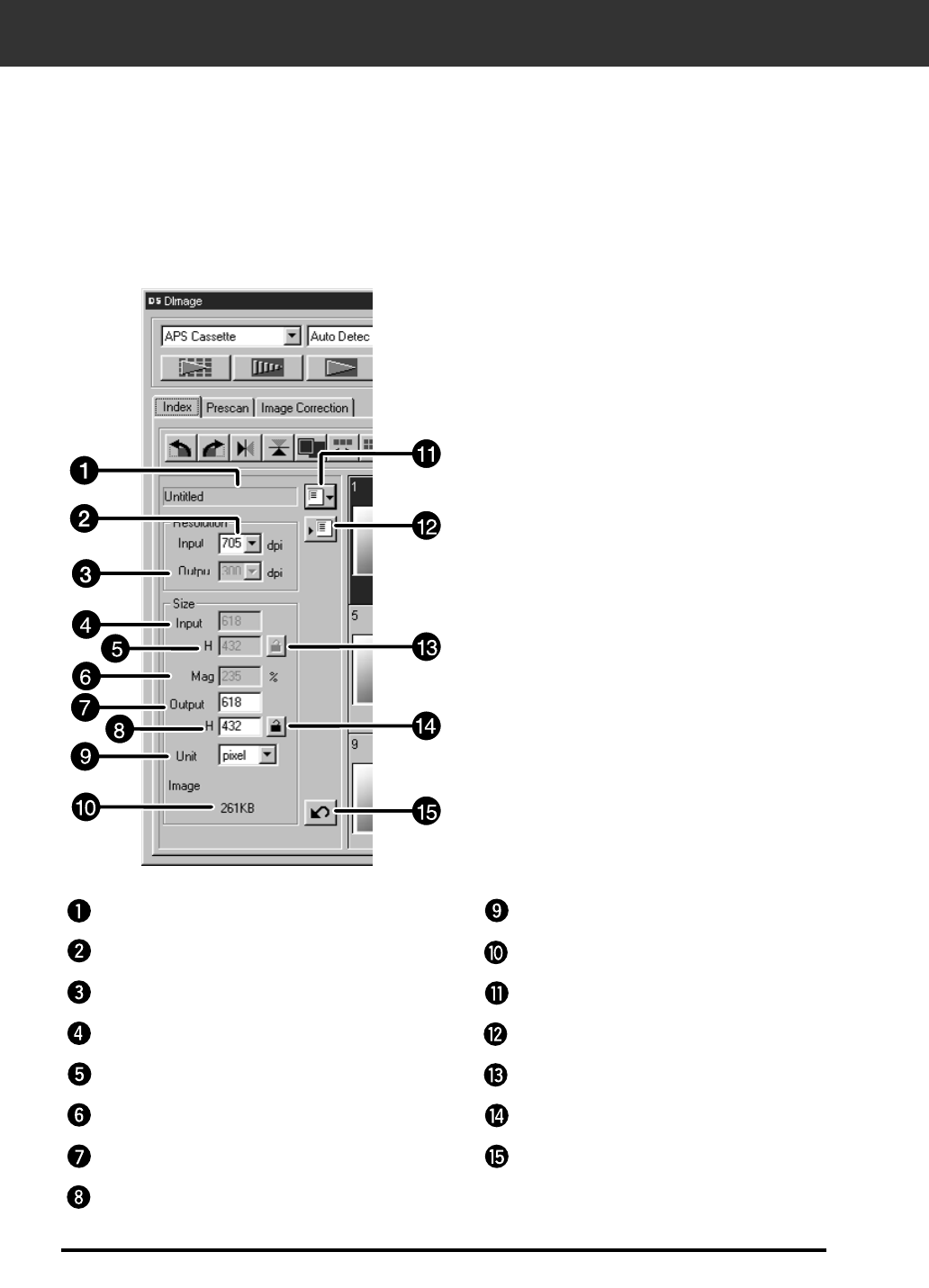
The Scan Settings part in the Main Window — Names of parts
Except the Image Correction window in the Main window.
Job Name list box
Output Size text box (H)
Units list box
Image size display
Job Load button
Job Registry button
Input Size lock button
Output Size lock button
Reset button
Input Resolution list box
Output Resolution list box
Input Size text box (W)
Input Size text box (H)
Magnification text box
Output Size text box (W)
SCAN SETTINGS
71
Image resolution is the number of pixels per inch (ppi or dpi) that represent your scanned image.
The size of an image file is determined by its size (dimensions) and resolution.
The rule to follow when scanning is "bigger is better". To obtain the best results, set the output
resolution to the highest value your final output device (printer, monitor, etc.) can handle. The driver
software automatically determines the input resolution necessary to obtain the desired output size
and resolution.
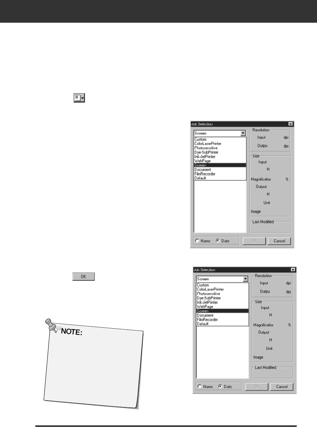
2. Select the appropriate category from the
drop-down list.
1. Click on in the Index window.
The Job Selection dialog box will appear.
3. Click on the job file name to select it, then
click on .
• The settings are applied to the active Preview
window.
Job names can be listed
chronologically or alphabetically.
Select the format by clicking on
the Name or Date option button.
• The cropping frame changes
accordingly, but can be
proportionally resized.
Continued on the following page.
72
SCAN SETTINGS
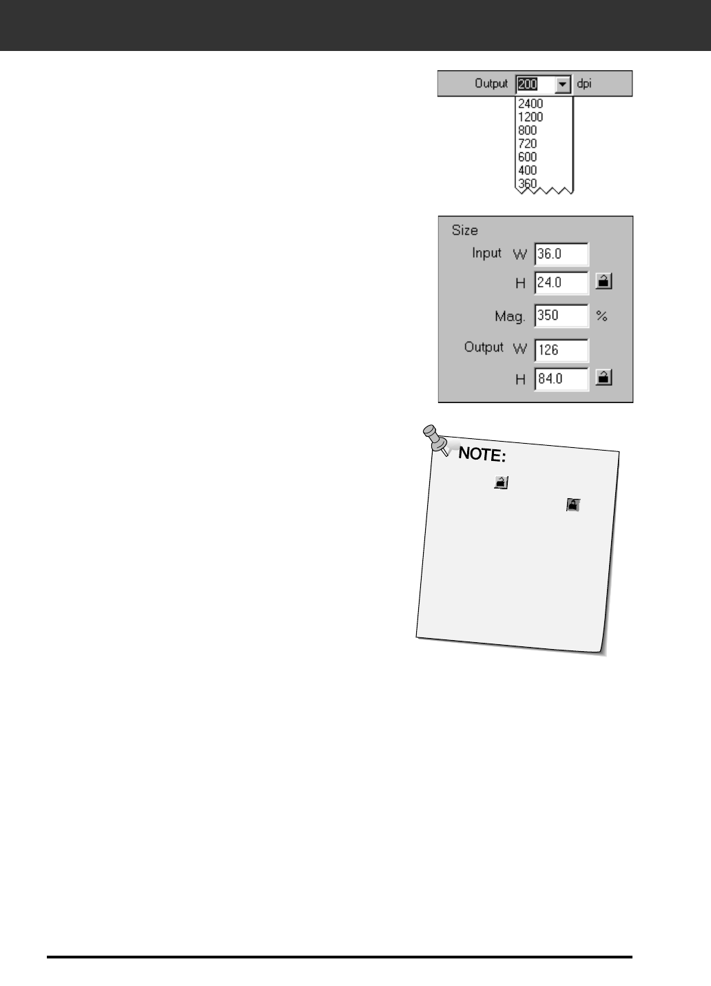
4. Enter the desired output resolution from the
output resolution drop-down list.
• Values can also be entered into the output resolution list box directly.
• The output resolution cannot be changed when the unit list box is set
to pixels.
5. The dimensions of the cropping frame are
displayed in the input size text boxes.
• Values can be entered directly or by resizing the cropping frame.
• The values will change if a different unit of measure is selected.
• The scanning area size can't be changed if the Input Size is locked.
6. Enter the desired output size (maximum 3 digits).
• The output size is limited by the maximum resolution of the scanner.
• The values will change if a different unit of measure is selected.
• The output size cannot be changed when the unit list box is set to
pixels.
• The scanning area size can be changed proportionally (within the
resolution limits) when the Output Size is locked.
7. The input scan resolution text box is set to the
lowest input (scan) resolution necessary to
achieve the desired output size and resolution.
• Input scan resolutions can also be selected from the drop down list
or entered directly.
• Click on to lock the settings.
The icon will change to .
Click again to unlock.
• The magnification text box
displays the output/input size
ratio as a percentage.
• Magnification values can be
entered directly.
CREATING / DELETING JOB FILES
73
In addition to the Job settings included with the software, it is possible to create and save your
own Job settings.
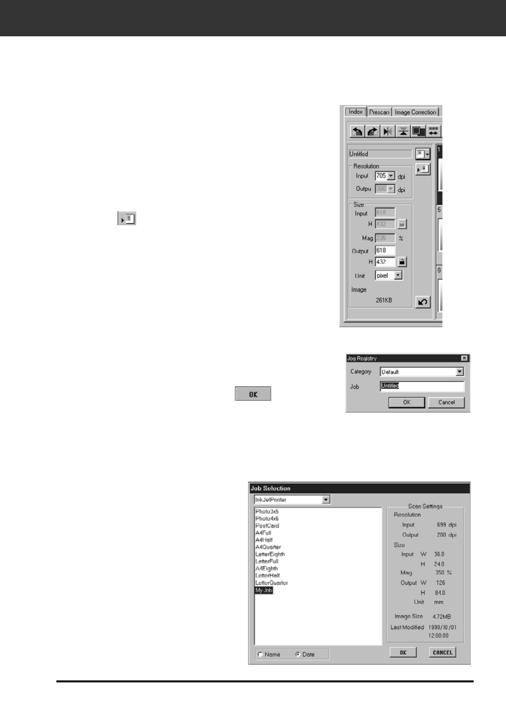
Creating a Job
1. Set the desired settings in the Main window (Index
window or Preview window).
2. Click on .
3. Name the job by entering a title and select the
desired category, then click on .
It is possible to delete the Job you created when it is no longer needed.
Deleting a Job
Click on the name of the job in the
Main window scan settings part,
then press the delete key on your
keyboard.
The Job Registry dialog box will appear
74
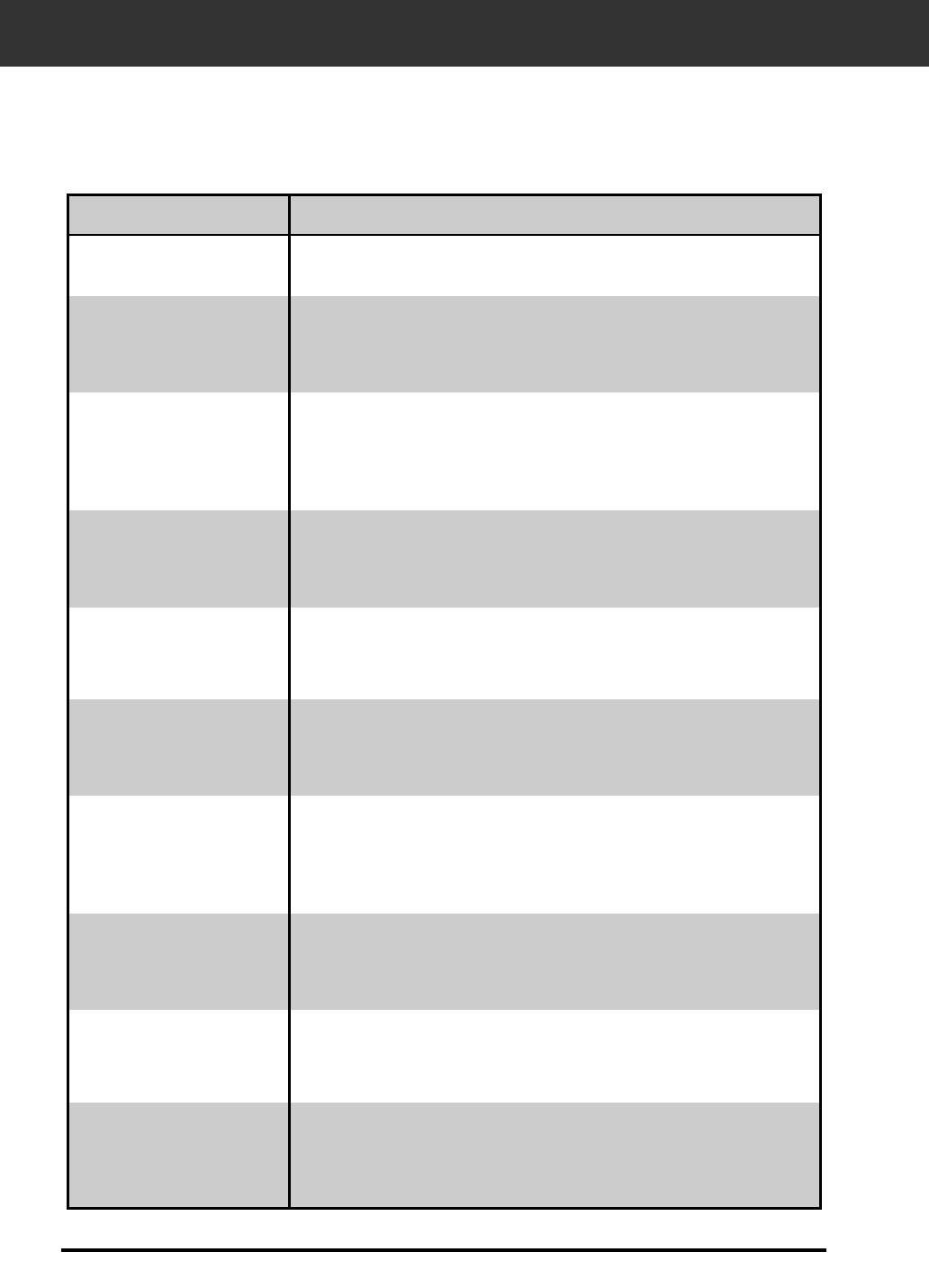
SCAN JOB TYPE
Before making the final scan, the scanner needs to know how big the final image will be and
the quality of output that will be used (printer, monitor, etc.) so it knows what resolution to scan
the film. Using the Job function is a quick and easy way to enter the scan settings.
Scan Job Category Description
Custom User created scan settings (p. 71).
Color Laser
Printer
Digital colour copiers and colour laser printers
Uses output resolution of 400 or 600 dpi. There are two
paper-size options; letter and A4.
Photosensitive Printers that use photosensitive/photographic material
Can use output resolutions of 400 dpi, 360 dpi, 267 dpi,
and 180 dpi. There are ten paper size options.
Dye-Sub Printer Dye-sublimation printers
Uses an output resolution of 300 dpi. There are 4 paper
size options.
Ink Jet Printer Uses an output resolution of 200 dpi. There are 4 paper
size options.
Web Page For use on home pages
Image size is listed in pixels and will vary. Standard
Photo CD sizes are also available.
Screen For monitor display
Image size is listed in pixels and will be the VGA
standard of 640 x 480 pixels or larger.
Document For insertion into documents
Uses an output resolution of 72 dpi. Image size depends
on the paper size selected.
Film Recorder For high input resolution images that will be output to a
film recorder.
Default This category uses the default settings for the film
format. The scan settings appear in the Job Selection
window.

SCAN JOB FILE LIST – 35MM
75
Default Default 705 300 235 pixel 1008 672 OFF 1008 672 OFF
Color Laser Printer Max Size_600dpi 2820 600 470 mm 36.3 24.2 OFF 170.00 113.00 ON
A4Quarter_600dpi 2447 600 407 mm 36.3 24.2 OFF 148.00 98.70 ON
A4Eighth_600dpi 1735 600 289 mm 36.3 24.2 OFF 105.00 70.00 ON
Letter Quarter_600dpi 2291 600 381 inch 1.43 0.95 OFF 5.46 3.64 ON
Letter Eighth_600dpi 1702 600 283 inch 1.43 0.95 OFF 4.05 2.70 ON
Max Size_400dpi 2820 400 705 mm 36.3 24.2 OFF 256.00 170.00 ON
A4Half_400dpi 2313 400 578 mm 36.3 24.2 OFF 210.00 140.00 ON
A4Quarter_400dpi 1629 400 407 mm 36.3 24.2 OFF 147.00 98.00 ON
A4Eighth_400dpi 1156 400 289 mm 36.3 24.2 OFF 105.00 69.90 ON
Letter Half_400dpi 2291 400 572 inch 1.42 0.95 OFF 8.19 5.46 ON
Letter Quarter_400dpi 1526 400 381 inch 1.43 0.95 OFF 5.45 3.63 ON
Letter Eighth_400dpi 1133 400 283 inch 1.43 0.95 OFF 4.05 2.70 ON
Photosensitive Max Size 2820 400 705 mm 36.3 24.2 OFF 256.00 170.00 ON
A5_400dpi 2313 400 578 mm 36.3 24.2 OFF 210.00 140.00 ON
8x10_400dpi 2798 400 699 inch 1.43 0.95 OFF 10.00 6.66 ON
5x7_400dpi 1961 400 490 inch 1.43 0.95 OFF 7.01 4.67 ON
PostCard4 6_400dpi 1678 400 419 inch 1.43 0.95 OFF 6.00 4.00 ON
Letter_267dpi 2039 267 763 inch 1.43 0.95 OFF 10.90 7.27 ON
A4_267dpi 2187 267 819 mm 36.3 24.2 OFF 297.00 198.00 ON
A5_267dpi 1545 267 578 mm 36.3 24.2 OFF 210.00 140.00 ON
8x10_267dpi 1870 267 700 inch 1.43 0.95 OFF 10.00 6.67 ON
5x7_267dpi 1307 267 489 inch 1.43 0.95 OFF 7.00 4.66 ON
PostCard4 6_267dpi 1120 267 419 inch 1.43 0.95 OFF 6.00 4.00 ON
(unavailable) 1597 360 443 mm 36.3 24.2 OFF 161.00 107.00 ON
2L_360dpi 1727 360 479 mm 36.3 24.2 OFF 174.00 116.00 ON
14x17_180dpi 2123 180 1179 mm 36.3 24.2 OFF 428.00 285.00 ON
11x14_180dpi 1747 180 970 mm 36.3 24.2 OFF 352.00 235.00 ON
10x12_180dpi 1494 180 830 mm 36.3 24.2 OFF 301.00 200.00 ON
(unavailable) 797 180 442 mm 36.3 24.2 OFF 160.00 106.00 ON
2L_180dpi 857 180 476 mm 36.3 24.2 OFF 173.00 115.00 ON
Dye-Sub Printer A4Full 2455 300 818 mm 36.3 24.2 OFF 297.00 198.00 ON
A4Half 1735 300 578 mm 36.3 24.2 OFF 210.00 140.00 ON
A4Quarter 1223 300 407 mm 36.3 24.2 OFF 148.00 98.70 ON
A4Eighth 866 300 289 mm 36.3 24.2 OFF 104.00 69.90 ON
Letter Full 2291 300 763 inch 1.43 0.95 OFF 10.90 7.28 ON
Letter Half 1714 300 571 inch 1.43 0.95 OFF 8.17 5.44 ON
Letter Quarter 1144 300 381 inch 1.43 0.95 OFF 5.45 3.63 ON
Letter Eighth 850 300 283 inch 1.43 0.95 OFF 4.05 2.70 ON
(unavailable) 1223 300 407 mm 36.3 24.2 OFF 148.00 98.70 ON
Photo4x6 1240 300 413 mm 36.3 24.2 OFF 150.00 100.00 ON
Photo3x5 /Photo9x13 1049 300 349 mm 36.3 24.2 OFF 127.00 84.60 ON
Ink-Jet Printer A4Full 163 200 818 mm 36.3 24.2 OFF 297.00 198.00 ON
A4Half 1156 200 578 mm 36.3 24.2 OFF 210.00 139.00 ON
A4Quarter 814 200 407 mm 36.3 24.2 OFF 148.00 98.50 ON
A4Eighth 577 200 288 mm 36.4 24.3 OFF 105.00 69.80 ON
Letter Full 1526 200 763 inch 1.42 0.95 OFF 10.90 7.27 ON
Letter Half 1144 200 572 inch 1.42 0.95 OFF 8.17 5.45 ON
Letter Quarter 763 200 381 inch 1.43 0.95 OFF 5.45 3.63 ON
Letter Eighth 566 200 283 inch 1.43 0.95 OFF 4.05 2.70 ON
(unavailable) 814 200 407 mm 36.3 24.2 OFF 148.00 98.50 ON
Photo4x6 826 200 413 mm 36.3 24.2 OFF 150.00 100.00 ON
Photo3x5 /Photo9x13 699 200 349 mm 36.3 24.0 OFF 127.00 84.50 ON
Category Job name Resolution
In Out Mag. Unit Input Size
WH Input
Lock Output Size
WH
Output
Lock
For your reference, the following is a listing of the scan job categories and names for the 35mm and
APS film formats.
Continued on the following page.

76
SCAN JOB FILE LIST – 35MM
Web Page 1023 x 682 716 300 238 pixel 1023 682 OFF 1023 682 ON
960 x 640 671 300 223 pixel 960 640 OFF 960 640 ON
870 x 580 608 300 202 pixel 870 580 OFF 870 580 ON
768 x 512 537 300 179 pixel 768 512 OFF 768 512 ON
624 x 416 436 300 145 pixel 624 416 OFF 624 416 ON
600 x 400 419 300 139 pixel 600 400 OFF 600 400 ON
480 x 320 335 300 111 pixel 480 320 OFF 480 320 ON
Photo CD 2048 x 3072 2148 300 716 pixel 3072 2048 OFF 3072 2048 ON
Photo CD 1024 x 1536 1074 300 358 pixel 1536 1024 OFF 1536 1024 ON
Photo CD512 x 768 537 300 179 pixel 768 512 OFF 768 512 ON
Photo CD256 x 348 243 300 81 pixel 348 232 OFF 348 232 ON
Screen 1280 x 1024 895 300 298 pixel 1280 853 OFF 1280 853 ON
1280 x 960 895 300 298 pixel 1280 853 OFF 1280 853 ON
1152 x 870 805 300 268 pixel 1152 768 OFF 1152 768 ON
1024 x 768 716 300 238 pixel 1024 682 OFF 1024 682 ON
832 x 624 582 300 194 pixel 832 554 OFF 832 554 ON
800 x 600 559 300 186 pixel 800 533 OFF 800 533 ON
640 x 480 47 300 149 pixel 640 426 OFF 640 426 ON
Document A4 Half 416 72 577 mm 36.3 24.2 OFF 210.00 139.00 ON
A4 Quarter 293 72 406 mm 36.4 24.1 OFF 148.00 98.40 ON
A4 Eighth 207 72 287 mm 36.4 24.3 OFF 105.00 70.00 ON
Letter Half 411 72 570 inch 1.43 0.95 OFF 8.16 5.44 ON
Letter Quarter 274 72 379 inch 1.43 0.95 OFF 5.44 3.62 ON
Letter Eighth 203 72 281 inch 1.44 0.96 OFF 4.04 2.69 ON
Film Recorder 35mm Full-Frame 2382 2400 99 mm 36.30 24.20 OFF 36.00 24.00 ON
35mm Half-Frame 1586 2400 66 mm 36.30 24.20 OFF 24.00 16.00 ON
35mm Quarter-Frame 1189 2400 49 mm 36.7 24.40 OFF 18.00 11.90 ON
Category Job Name Resolution
In Out Mag. Unit Input Size
WH Input
Lock Output Size
WH
Output
Lock

SCAN JOB FILE LIST – APS
77
Default Default 705 300 235 pixel 832 480 OFF 832 480 OFF
Color Laser Printer Max Size_600dpi 2820 600 470 mm 29.9 17.2 OFF 140.00 81.20 ON
A4 Eighth_600dpi 2104 600 350 mm 30.0 17.3 OFF 105.00 60.60 ON
Letter Eighth_600dpi 2161 600 360 inch 1.18 0.68 OFF 4.25 2.45 ON
Max Size_400dpi 2820 400 705 mm 29.9 17.2 OFF 211.00 121.00 ON
A4 Half_400dpi 2809 400 702 mm 29.9 17.2 OFF 210.00 121.00 ON
A4 Quarter_400dpi 1977 400 494 mm 30.0 17.3 OFF 148.00 85.40 ON
A4 Eighth_400dpi 1401 400 350 mm 30.0 17.3 OFF 105.00 60.60 ON
Letter Quarter_400dpi 1851 400 462 inch 1.18 0.68 OFF 5.46 3.15 ON
Letter Eighth_400dpi 1440 400 360 inch 1.18 0.68 OFF 4.25 2.45 ON
Photosensitive Max Size 2820 400 705 mm 29.9 17.2 OFF 211.00 121.00 ON
A5_400dpi 2809 400 702 mm 29.9 17.2 OFF 210.00 121.00 ON
5x7_400dpi 2374 400 593 inch 1.18 0.68 OFF 7.00 4.04 ON
Post Card 4 x 6_400dpi 2039 400 509 inch 1.18 0.68 OFF 6.01 3.47 ON
Letter_267dpi 2472 267 925 inch 1.18 0.68 OFF 10.90 6.30 ON
A4_267dpi 2654 267 994 mm 29.9 17.2 OFF 297.00 171.00 ON
A5_267dpi 1870 267 700 mm 30.0 17.2 OFF 210.00 121.00 ON
8x10_267dpi 2263 267 847 inch 1.18 0.68 OFF 10.00 5.76 ON
5x7_267dpi 1586 267 594 inch 1.17 0.68 OFF 7.00 4.04 ON
PostCard4 x 6_267dpi 1359 267 508 inch 1.18 0.68 OFF 6.00 3.46 ON
(unavailable) 1935 360 537 mm 30.0 17.3 OFF 161.00 92.90 ON
2L_360dpi 2092 360 581 mm 29.9 17.2 OFF 174.00 100.00 ON
14x17_180dpi 2578 180 1432 mm 29.9 17.2 OFF 429.00 247.00 ON
11x14_180dpi 2117 180 1176 mm 29. 17.2 OFF 352.00 203.00 ON
10x12_180dpi 1809 180 1005 mm 29.9 17.2 OFF 301.00 173.00 ON
(unavailable) 966 180 536 mm 30.0 17.2 OFF 160.00 92.70 ON
2L_180dpi 1046 180 581 mm 29.9 17.2 OFF 174.00 100.00 ON
Dye-Sub Printer Max Size 2820 300 940 mm 29.9 17.2 OFF 281.00 162.00 ON
A4 Half 2104 300 701 mm 29.9 17.3 OFF 210.00 121.00 ON
A4 Quarter 1482 300 494 mm 29.9 17.2 OFF 148.00 85.40 ON
A4 Eighth 1050 300 350 mm 30.0 17.3 OFF 105.00 60.50 ON
Letter Full 2776 300 925 inch 1.18 0.68 OFF 10.90 6.30 ON
Letter Half 2161 300 720 inch 1.18 0.68 OFF 8.50 4.90 ON
Letter Quarter 1385 300 461 inch 1.18 0.68 OFF 5.45 3.14 ON
Letter Eighth 1080 300 360 inch 1.18 0.68 OFF 4.25 2.45 ON
(unavailable) 1500 300 500 mm 30.0 17.2 OFF 150.00 86.40 ON
Photo 9x13 1270 300 423 mm 30.0 17.2 OFF 127.00 73.00 ON
Ink-Jet Printer A4 Full 1977 200 988 mm 30.0 17.3 OFF 297.00 171.00 ON
A4 Half 1401 200 700 mm 30.0 17.3 OFF 210.00 121.00 ON
A4 Quarter 987 200 493 mm 30.0 17.3 OFF 148.00 85.30 ON
A4 Eighth 700 200 350 mm 30.0 17.3 OFF 105.00 60.40 ON
Letter Full 1846 200 923 inch 1.18 0.68 OFF 10.90 6.28 ON
Letter Half 1440 200 720 inch 1.18 0.68 OFF 8.50 4.90 ON
Letter Quarter 924 200 462 inch 1.17 0.68 OFF 5.45 3.14 ON
Letter Eighth 720 200 360 inch 1.18 0.68 OFF 4.25 2.45 ON
Photo 4 x 6 1001 200 500 mm 30.0 17.3 OFF 150.00 86.40 ON
Photo 3.5 x 5/Photo 9 x 13 846 200 423 mm 30.0 17.2 OFF 127.00 73.00 ON
Web Page 1280 x 739 1085 300 361 pixel 1280 739 OFF 1280 739 ON
1152 x 665 976 300 665 pixel 1152 665 OFF 1152 665 ON
1024 x 590 867 300 239 pixel 1024 590 OFF 1024 590 ON
832 x 480 705 300 235 pixel 832 480 OFF 832 480 ON
800 x 461 678 300 226 pixel 800 461 OFF 800 461 ON
640 x 369 542 300 180 pixel 640 369 OFF 640 369 ON
Photo CD1024 x 1536 1303 300 434 pixel 1536 887 OFF 1536 887 ON
Photo CD512 x 768 650 300 216 pixel 768 443 OFF 768 443 ON
Photo CD256 x 348 294 300 98 pixel 348 200 OFF 348 200 ON
Screen 1280 x 1024 1085 300 361 pixel 1280 739 OFF 1280 739 ON
1280 x 960 1085 300 361 pixel 1280 739 OFF 1280 739 ON
1152 x 870 976 300 325 pixel 1152 665 OFF 1152 665 ON
1024 x 768 867 300 289 pixel 1024 590 OFF 1024 590 ON
832 x 624 705 300 235 pixel 832 480 OFF 832 480 ON
800 x 600 678 300 226 pixel 800 461 OFF 800 461 ON
640 x 480 542 300 369 pixel 640 369 OFF 640 369 ON
Document A4 Half 504 72 700 mm 30.0 17.3 OFF 210.00 121.00 ON
A4 Quarter 355 72 493 mm 30.0 17.3 OFF 148.00 85.00 ON
A4 Eighth 251 72 348 mm 30.0 17.3 OFF 105.00 60.30 ON
Letter Half 518 72 719 inch 1.18 0.68 OFF 8.50 4.90 ON
Category Job name Resolution
In Out Mag. Unit Input Size
WH Input
Lock Output Size
WH
Output
Lock

78
GLOSSARY
BRIGHTNESS The lightness or darkness of the image.
CHANNEL The component of an image.Your scanned image has three
channels: red, green, and blue (RGB).
CONTRAST The gradation of shades in an image. A high contrast image
has very dark areas and bright areas without many middle
shades. A low contrast image has many tones that are close to
the same brightness. Low contrast images are often described
as looking ‘flat’.
CROP To trim and delete the unwanted edges of the image.
DPI Dots (pixels) per inch.
EMULSION SIDE The side of the film coated with the photographic material.
GAMMA The contrast of only the middle tones.
HIGHLIGHTS The lighter areas of the image.
HISTOGRAM A graph showing the amount of each level of the 256
brightness levels.
INTERPOLATION A form of adding new pixels in an image when resampling up.
JPEG The JPEG (Joint Photographic Experts Group) compression
standard is capable of producing a high compression ratio
while maintaining image quality. JPEG is a widely supported
image file format.
MIDTONE The middle shades of an image, in between light and dark.
NEUTRAL Having no colour cast, such as black, white, or gray.
PICT (Macintosh operating system only) The PICT graphic file format
uses a lossless compression scheme and is compatible with
many Macintosh applications.
PIXEL Abbreviation for picture element. The dots that make up an
electronic image.

GLOSSARY
79
RESAMPLE To change the number of pixels in the image. If pixels are
discarded when shrinking an image, it is called resampling
down. If new pixels are created in an image, it is called
resampling up.
RESOLUTION The number of pixels in a given area of the image; such as
pixels per inch or pixels per centimeter. High resolution is the
term for an image with a lot of pixels in a given area. Low
resolution means there are not many pixels in a given area.
RGB Red, Green, and Blue. These are the colours of the three
channels that make up the scanned image. Monitors use red,
green, and blue phosphors to create the image you see on the
screen.
SHADOWS The dark areas of an image.
TIFF Tagged Image File Format (TIFF) files contain bit-mapped
data. In addition to being a widely supported format, TIFF is
able to handle the colour palette needed for professional-
quality images and graphics.
WINDOWS®BMP (Windows only)The BMP graphic file format is for bit-mapped
images. BMP images are supported by the Paint accessory
and can easily be opened on most PCs running Windows.
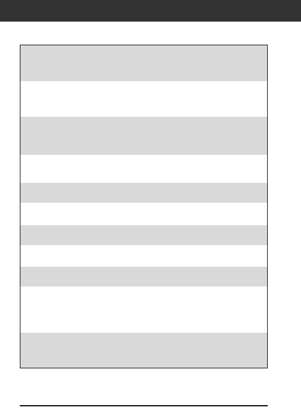
80
TROUBLE SHOOTING
• Load film into the film holder.
• Scanner door opened during setup. Close
scanner door.
The computer will not start up
after connecting the scanner.
• Shut down the computer and all the devices in
your SCSI chain, then check the SCSI cables,
SCSI ID connection, power cord, and SCSI ID.
DS_Elite does not appear in
the Import drop down list.
• Make sure the plug-in module has been
placed in the correct folder. See page 12.
“Could not establish
connection with scanner.”
• Indicator lamp is off - Turn the Dimâge Scan
Elite on, then restart your system.
• Check that the SCSI ID is not being used by
another SCSI device.
“Setting up now. Remove the
film holder.”
• Remove the film holder and click on OK.
“Set film properly…”
Indicator lamp blinking
rapidly (8Hz).
“Set 35mm film holder
properly.”
• Set the correct film type.
“Set APS film holder properly.” • Set the correct film type.
“Could not recognize the
film type.”
• Set the film type manually.
“Insufficient Memory” • Increase the memory requirements for the
host application.
• If you have scanned multiple images, close
and relaunch the host application.
“Setting up now. Remove
the film holder.” appears
when the film holder is not
loaded.
• Contact a Minolta Service Facility to change
the fluorescent lamp.
SYMPTOM or MESSAGE SOLUTION
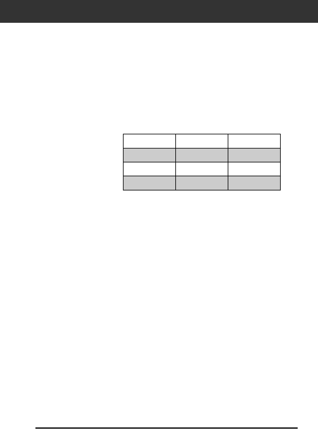
81
Type: Fixed sensor, film transport, single pass
Usable Film: 35mm - negative/ positive, colour/ B&W
APS cassette (with optional adapter) - colour/ B&W,
negative/ positive
Scanning Dimensions: 35mm - 24.2 x 36.3mm (2688 x 4032 pixels)
APS - 17.28 x 29.95mm (1920 x 3328 pixels)
Optical Input Resolution: 2820 dpi
A/D Conversion: 12 bit
Image Sensor: RGB 3-line CCD (2700 pixels)
Scan Times (approx):
SPECIFICATIONS
Interface: SCSI-2
SCSI Ports: DB25, Centronics 50
Light Source: 3 Wavelength Cold Cathode Fluorescent
Power/Frequency: Product for North America - 100-120 volts AC, 50/60 Hz
Product for Europe - 220-240 volts AC, 50/60 Hz
This device is to be used with a power source within the voltege as specified
on the buck of unit.
Power Consumption: Max. 30W
Dimensions (W x H x D): 90.5 x 160.5 x 272mm (3.6 x 6.3 x 10.7 in.)
Weight (approx): 2.0kg (4.4 lbs.)
Specifications are based on the latest information available at
the time of printing and are subject to change without notice.
35mm APS
Prescan 6 sec 6 sec
Scan 40 sec 40 sec
Index Scan - - 6 sec/frame

82
USER TECHNICAL SUPPORT
Please contact your dealer for information regarding installation, SCSI-2 interface
recommendations, or application compatibility. If you dealer is unable to help you, contact one
of the distributors listed on the back cover.
Please have the following information ready when calling Minolta
Technical Support.
Determining the version number of your driver software:
Place the pointer on the status window in the command window to display the version number
and SCSI ID.
Make and Model of your computer:
Available application RAM:
Operating System version:
Other connected SCSI devices:
DS Elite driver version number:
Symptoms:
Messages that appear on the screen when the problem occurs:
Frequency of occurrence:

83
NOTES
