Konica 7145 Service Manual Safety
Minolta-7145-Service-Manual-790210 minolta-7145-service-manual-790210
7235 - Service Manual 7145-7222-7228-7235_SM Free User Guide for Konica Minolta Camera, Manual - page1
2015-08-19
: Konica Konica-7145-Service-Manual-788160 konica-7145-service-manual-788160 konica pdf
Open the PDF directly: View PDF ![]() .
.
Page Count: 448 [warning: Documents this large are best viewed by clicking the View PDF Link!]
- 7145/7222/7228/7235 SERVICE MANUAL
- GENERAL SECTION
- DISCLAIMER
- CONTENTS
- SAFETY AND IMPORTANT WARNING ITEMS
- SAFETY INFORMATION
- LIST OF DIFFERENCES
- LIST OF OPTIONS
- I. OUTLINE
- II. UNIT EXPLANATION
- III. DISASSEMBLY/ASSEMBLY
- 1. EXTERNAL SECTION
- 2. DRIVE SECTION
- 3. SCANNER SECTION
- 4. WRITE UNIT
- 5. DRUM UNIT
- 5.1 Removing/Reinstalling Drum Unit
- 5.2 Removing/Reinstalling Charging Corona Unit
- 5.3 Removing/Reinstalling Charge Control Plate
- 5.4 Replacing Charging Wire
- 5.5 Removing/Reinstalling Drum
- 5.6 Removing/Reinstalling Separation Claw
- 5.7 Removing/Reinstalling Transfer and Separation Corona Unit
- 5.8 Replacing Transfer/Separation Wires
- 6. DEVELOPING UNIT
- 7. TONER SUPPLY/CLEANING/ RECYCLE UNIT
- 8. PAPER FEED UNIT
- 9. FIXING UNIT
- 9.1 Removing/Reinstalling Fixing Unit
- 9.2 Replacing Heater Lamps
- 9.3 Removing/Reinstalling Claw
- 9.4 Replacing Web
- 9.5 Removing/Reinstalling Heat Roller, Pressure Roller, Heat Insulating Sleeves, Idling Gears, Bearings, Heater Lamps
- 9.6 Removing/Reinstalling Temperature Sensors
- 9.7 Removing/Reinstalling Fuse Mounting Plate Assembly
- SERVICE SECTION
- DISCLAIMER
- CONTENTS
- SAFETY AND IMPORTANT WARNING ITEMS
- SAFETY INFORMATION
- I. ADJUSTMENT
- 1. HOW TO USE THE ADJUSTMENT SECTION
- 2. ADJUSTMENTS WHEN REPLACING PARTS
- 3. LIST OF ADJUSTMENT ITEMS
- 4. CE PASSWORD SETTING
- 5. MODE CHANGE MENU
- 6. CHECKING BY THE COUNTER KEY FUNCTION
- 7. 25 MODE
- 7.1 Setting Method
- 7.2 Setting Software DIPSW
- 7.3 PM Count Setting
- 7.4 Data Collection
- 7.5 Copy Count for Each Part to be Replaced
- 7.6 Password Setting
- 7.7 Setting Phone Number of the Service Center
- 7.8 Setting the Serial Number/Destination
- 7.9 Displaying the ROM Version
- 7.10 KRDS Setting
- 7.11 ISW Setting
- 7.12 Root Counter Display
- 7.13 Setting Date
- 7.14 Tray Size Setting
- 8. 36 MODE
- 8.1 Setting Method
- 8.2 Process Adjustment
- 8.3 L Detection Adjustment
- 8.4 Toner Density Adjustment
- 8.5 Dot Diameter Adjustment
- 8.6 LD1 Offset Adjustment
- 8.7 LD2 Offset Adjustment (7145 only)
- 8.8 Timing Adjustment
- 8.9 Running Test Mode
- 8.10 Test Pattern Output
- 8.11 Test Pattern Density Adjustment
- 8.12 Image Quality Adjustment
- 8.13 List Print
- 8.14 Counter Clear
- 8.15 Adjustment of RADF
- 8.16 FNS Adjustment (FS-112 only)
- 8.17 FNS Adjustment (FS-114 only)
- 9. 47 MODE
- 10.OTHER ADJUSTMENTS
- 10.1 RADF Height Adjustment
- 10.2 RADF Distortion Adjustment
- 10.3 RADF Original Skew Adjustment (Front Side)
- 10.4 RADF Original Skew Adjustment (Back Side)
- 10.5 DB-411 Paper-Centering Adjustment
- 10.6 DB-411 Tray Tilt Adjustment
- 10.7 LT Tray Tilt Adjustment
- 10.8 FS-113 Output Check Mode
- 10.9 Lengthwise Position Adjustment of Punch Hole of FS-113
- 10.10 Adjustment of FS-113 Solenoids
- 10.11 FS-113 Timing Belt Tension Adjustment
- 10.12 FS-113 Adjustment of the Elevator Tray Upper Limit Sensor
- 10.13 Adjustment of FS-113 Elevator Tray Overload Detection Level
- 10.14 Staple Position Adjustment of FS-114
- 10.15 Adjustment of the Installation Position of the Shutter Drive Gear of FS-114
- 10.16 Punch Hole Deviance Adjustment of FS-114 (PK-114)
- 10.17 Fold Angle Adjustment of SK-114
- 10.18 Staple Angle Adjustment of SK-114
- II. ISW
- III. SERVICE
- IV. DIAGRAMS
- 1. PARTS LAYOUT DRAWING
- 2. CONNECTOR LAYOUT DRAWING
- 3. JAM CODE LIST
- 4. ERROR CODE LIST
- 5. TIMING CHART
- 6. OVERALL WIRING DIAGRAM
- 7. APPENDIX
- 7.1 7145 Overall Wiring Diagram (1/4)
- 7.2 7145 Overall Wiring Diagram (2/4)
- 7.3 7145 Overall Wiring Diagram (3/4)
- 7.4 7145 Overall Wiring Diagram (4/4)
- 7.5 7235/7228/7222 Overall Wiring Diagram (1/4)
- 7.6 7235/7228/7222 Overall Wiring Diagram (2/4)
- 7.7 7235/7228/7222 Overall Wiring Diagram (3/4)
- 7.8 7235/7228/7222 Overall Wiring Diagram (4/4)
- 7.9 FS-114 Overall Wiring Diagram
- GENERAL SECTION

SERVICE MANUAL
Models
7145/7222/7228/7235
APRIL 2004
CSM-7145/7222/7228/7235
KONICA MINOLTA BUSINESS SOLUTIONS U.S.A., INC.

7145/7222/7228/7235
SERVICE MANUAL
APRIL 2004

IMPORTANT NOTICE
Because of the possible hazards to an inexperienced
person servicing this equipment, as well as the risk of
damage to the equipment, Konica Minolta Business
Solutions U.S.A., Inc. strongly recommends that all
servicing be performed by Konica Minolta-trained serv-
ice technicians only.
Changes may have been made to this equipment to
improve its performance after this service manual was
printed. Accordingly, Konica Minolta Business Solutions
U.S.A., Inc., makes no representations or warranties,
either expressed or implied, that the information con-
tained in this service manual is complete or accurate. It
is understood that the user of this manual must assume
all risks or personal injury and/or damage to the equip-
ment while servicing the equipment for which this serv-
ice manual is intended.
© 2004, KONICA MINOLTA BUSINESS SOLUTIONS U.S.A. , INC.
All rights reserved.
Printed in U.S.A.
Corporate Publications Department

CONTENTS
i
I OUTLINEII UNIT EXPLANATIONIII DIS./ASSEMBLY
2
CONTENTS
SAFETY AND IMPORTANT WARNING ITEMS . . . . . . . . . . . . . . . . . . . . . . . . . . . . . . . . . . . . . . . . . . . . S-1
IMPORTANT NOTICE . . . . . . . . . . . . . . . . . . . . . . . . . . . . . . . . . . . . . . . . . . . . . . . . . . . . . . . . . . . . . . . S-1
DESCRIPTION ITEMS FOR DANGER, WARNING AND CAUTION . . . . . . . . . . . . . . . . . . . . . . . . . . . . S-1
SAFETY WARNINGS . . . . . . . . . . . . . . . . . . . . . . . . . . . . . . . . . . . . . . . . . . . . . . . . . . . . . . . . . . . . . . . . S-2
SAFETY INFORMATION . . . . . . . . . . . . . . . . . . . . . . . . . . . . . . . . . . . . . . . . . . . . . . . . . . . . . . . . . . . . . S-10
IMPORTANT INFORMATION . . . . . . . . . . . . . . . . . . . . . . . . . . . . . . . . . . . . . . . . . . . . . . . . . . . . . . . . . S-10
SAFETY CIRCUITS . . . . . . . . . . . . . . . . . . . . . . . . . . . . . . . . . . . . . . . . . . . . . . . . . . . . . . . . . . . . . . . . S-11
INDICATION OF WARNING ON THE MACHINE . . . . . . . . . . . . . . . . . . . . . . . . . . . . . . . . . . . . . . . . . . S-13
List of major differences between the 7145, 7235, 7228 and 7222 . . . . . . . . . . . . . . . . . . . . . . . . . . . . . . . . 1
List of options corresponding to the 7145/7235/7228/7222 . . . . . . . . . . . . . . . . . . . . . . . . . . . . . . . . . . . . . . 3
I OUTLINE
1. OUTLINE OF SYSTEM . . . . . . . . . . . . . . . . . . . . . . . . . . . . . . . . . . . . . . . . . . . . . . . . . . . . . . . . . . . . 1-1
2. PRODUCT SPECIFICATIONS . . . . . . . . . . . . . . . . . . . . . . . . . . . . . . . . . . . . . . . . . . . . . . . . . . . . . . . 1-3
A. Type. . . . . . . . . . . . . . . . . . . . . . . . . . . . . . . . . . . . . . . . . . . . . . . . . . . . . . . . . . . . . . . . . . . . . . . . 1-3
B. Functions . . . . . . . . . . . . . . . . . . . . . . . . . . . . . . . . . . . . . . . . . . . . . . . . . . . . . . . . . . . . . . . . . . . . 1-3
C. Copy paper . . . . . . . . . . . . . . . . . . . . . . . . . . . . . . . . . . . . . . . . . . . . . . . . . . . . . . . . . . . . . . . . . . 1-5
D. Machine data . . . . . . . . . . . . . . . . . . . . . . . . . . . . . . . . . . . . . . . . . . . . . . . . . . . . . . . . . . . . . . . . . 1-5
E. Maintenance . . . . . . . . . . . . . . . . . . . . . . . . . . . . . . . . . . . . . . . . . . . . . . . . . . . . . . . . . . . . . . . . 1-5
F. Consumables. . . . . . . . . . . . . . . . . . . . . . . . . . . . . . . . . . . . . . . . . . . . . . . . . . . . . . . . . . . . . . . . . 1-5
G. Operating environment . . . . . . . . . . . . . . . . . . . . . . . . . . . . . . . . . . . . . . . . . . . . . . . . . . . . . . . . . 1-6
3. CENTER CROSS SECTION . . . . . . . . . . . . . . . . . . . . . . . . . . . . . . . . . . . . . . . . . . . . . . . . . . . . . . . . 1-7
4. DRIVE SYSTEM DIAGRAM . . . . . . . . . . . . . . . . . . . . . . . . . . . . . . . . . . . . . . . . . . . . . . . . . . . . . . . . . 1-8
4.1 Drum drive. . . . . . . . . . . . . . . . . . . . . . . . . . . . . . . . . . . . . . . . . . . . . . . . . . . . . . . . . . . . . . . . . . . 1-8
4.2 Cleaning/Developer agitation drive . . . . . . . . . . . . . . . . . . . . . . . . . . . . . . . . . . . . . . . . . . . . . . . . 1-8
4.3 Fixing/Paper exit section/IT-101/RU-101 drive . . . . . . . . . . . . . . . . . . . . . . . . . . . . . . . . . . . . . . . 1-9
4.4 Developing drive . . . . . . . . . . . . . . . . . . . . . . . . . . . . . . . . . . . . . . . . . . . . . . . . . . . . . . . . . . . . . . 1-9
4.5 Paper feed drive . . . . . . . . . . . . . . . . . . . . . . . . . . . . . . . . . . . . . . . . . . . . . . . . . . . . . . . . . . . . . 1-10
4.5.1 Drive from paper feed motor to loop clutch . . . . . . . . . . . . . . . . . . . . . . . . . . . . . . . . . . . . 1-10
4.5.2 Tray 1 drive . . . . . . . . . . . . . . . . . . . . . . . . . . . . . . . . . . . . . . . . . . . . . . . . . . . . . . . . . . . . 1-11
4.5.3 Tray 2 drive . . . . . . . . . . . . . . . . . . . . . . . . . . . . . . . . . . . . . . . . . . . . . . . . . . . . . . . . . . . . 1-11
4.5.4 Bypass feed drive . . . . . . . . . . . . . . . . . . . . . . . . . . . . . . . . . . . . . . . . . . . . . . . . . . . . . . . 1-12
4.5.5 Registration clutch drive. . . . . . . . . . . . . . . . . . . . . . . . . . . . . . . . . . . . . . . . . . . . . . . . . . . 1-12
4.6 ADU drive . . . . . . . . . . . . . . . . . . . . . . . . . . . . . . . . . . . . . . . . . . . . . . . . . . . . . . . . . . . . . . . . . . 1-13
4.7 Scanner drive . . . . . . . . . . . . . . . . . . . . . . . . . . . . . . . . . . . . . . . . . . . . . . . . . . . . . . . . . . . . . . . 1-14
4.8 Toner supply drive . . . . . . . . . . . . . . . . . . . . . . . . . . . . . . . . . . . . . . . . . . . . . . . . . . . . . . . . . . . . 1-15

CONTENTS
ii
I OUTLINEII UNIT EXPLANATIONIII DIS./ASSEMBLY
2
II UNIT EXPLANATION
1. SCANNER SECTION . . . . . . . . . . . . . . . . . . . . . . . . . . . . . . . . . . . . . . . . . . . . . . . . . . . . . . . . . . . . . . 2-1
1.1 Composition . . . . . . . . . . . . . . . . . . . . . . . . . . . . . . . . . . . . . . . . . . . . . . . . . . . . . . . . . . . . . . . . . . 2-1
1.2 Operation . . . . . . . . . . . . . . . . . . . . . . . . . . . . . . . . . . . . . . . . . . . . . . . . . . . . . . . . . . . . . . . . . . . . 2-2
1.2.1 Initial operation when power is turned on and shading correction reading. . . . . . . . . . . . . . 2-2
1.2.2 Original reading mode . . . . . . . . . . . . . . . . . . . . . . . . . . . . . . . . . . . . . . . . . . . . . . . . . . . . . 2-2
1.2.3 Original read control . . . . . . . . . . . . . . . . . . . . . . . . . . . . . . . . . . . . . . . . . . . . . . . . . . . . . . . 2-4
1.2.4 APS control. . . . . . . . . . . . . . . . . . . . . . . . . . . . . . . . . . . . . . . . . . . . . . . . . . . . . . . . . . . . . . 2-5
1.2.5 AE control . . . . . . . . . . . . . . . . . . . . . . . . . . . . . . . . . . . . . . . . . . . . . . . . . . . . . . . . . . . . . . . 2-7
1.2.6 Image processing . . . . . . . . . . . . . . . . . . . . . . . . . . . . . . . . . . . . . . . . . . . . . . . . . . . . . . . . . 2-8
2. WRITE UNIT . . . . . . . . . . . . . . . . . . . . . . . . . . . . . . . . . . . . . . . . . . . . . . . . . . . . . . . . . . . . . . . . . . . . . 2-9
2.1 Composition . . . . . . . . . . . . . . . . . . . . . . . . . . . . . . . . . . . . . . . . . . . . . . . . . . . . . . . . . . . . . . . . . . 2-9
2.2 Operation . . . . . . . . . . . . . . . . . . . . . . . . . . . . . . . . . . . . . . . . . . . . . . . . . . . . . . . . . . . . . . . . . . . 2-10
2.2.1 Image writing . . . . . . . . . . . . . . . . . . . . . . . . . . . . . . . . . . . . . . . . . . . . . . . . . . . . . . . . . . . 2-10
2.2.2 Write control . . . . . . . . . . . . . . . . . . . . . . . . . . . . . . . . . . . . . . . . . . . . . . . . . . . . . . . . . . . . 2-10
3. DRUM UNIT . . . . . . . . . . . . . . . . . . . . . . . . . . . . . . . . . . . . . . . . . . . . . . . . . . . . . . . . . . . . . . . . . . . . 2-11
3.1 Composition . . . . . . . . . . . . . . . . . . . . . . . . . . . . . . . . . . . . . . . . . . . . . . . . . . . . . . . . . . . . . . . . . 2-11
3.2 Operation . . . . . . . . . . . . . . . . . . . . . . . . . . . . . . . . . . . . . . . . . . . . . . . . . . . . . . . . . . . . . . . . . . . 2-13
3.2.1 Image formation timing (when copying two sheets) . . . . . . . . . . . . . . . . . . . . . . . . . . . . . . 2-13
4. DEVELOPING UNIT . . . . . . . . . . . . . . . . . . . . . . . . . . . . . . . . . . . . . . . . . . . . . . . . . . . . . . . . . . . . . . 2-15
4.1 Composition . . . . . . . . . . . . . . . . . . . . . . . . . . . . . . . . . . . . . . . . . . . . . . . . . . . . . . . . . . . . . . . . . 2-15
4.2 Operation . . . . . . . . . . . . . . . . . . . . . . . . . . . . . . . . . . . . . . . . . . . . . . . . . . . . . . . . . . . . . . . . . . . 2-16
4.2.1 Developing control . . . . . . . . . . . . . . . . . . . . . . . . . . . . . . . . . . . . . . . . . . . . . . . . . . . . . . . 2-16
4.2.2 Control of toner density in the developing unit . . . . . . . . . . . . . . . . . . . . . . . . . . . . . . . . . . 2-16
5. TONER SUPPLY/CLEANING/RECYCLE UNIT . . . . . . . . . . . . . . . . . . . . . . . . . . . . . . . . . . . . . . . . . 2-17
5.1 Composition . . . . . . . . . . . . . . . . . . . . . . . . . . . . . . . . . . . . . . . . . . . . . . . . . . . . . . . . . . . . . . . . . 2-17
5.2 Operation . . . . . . . . . . . . . . . . . . . . . . . . . . . . . . . . . . . . . . . . . . . . . . . . . . . . . . . . . . . . . . . . . . . 2-18
5.2.1 Toner supply control when the toner level in the toner supply section gets reduced . . . . . 2-18
5.2.2 Toner supply control when toner density in the developing unit gets reduced . . . . . . . . . . 2-19
6. PAPER FEED UNIT . . . . . . . . . . . . . . . . . . . . . . . . . . . . . . . . . . . . . . . . . . . . . . . . . . . . . . . . . . . . . . 2-20
6.1 Composition . . . . . . . . . . . . . . . . . . . . . . . . . . . . . . . . . . . . . . . . . . . . . . . . . . . . . . . . . . . . . . . . . 2-20
6.2 Operation . . . . . . . . . . . . . . . . . . . . . . . . . . . . . . . . . . . . . . . . . . . . . . . . . . . . . . . . . . . . . . . . . . . 2-21
6.2.1 Tray up drive control. . . . . . . . . . . . . . . . . . . . . . . . . . . . . . . . . . . . . . . . . . . . . . . . . . . . . . 2-21
6.2.2 Paper feed control . . . . . . . . . . . . . . . . . . . . . . . . . . . . . . . . . . . . . . . . . . . . . . . . . . . . . . . 2-22
6.2.3 Remaining paper detection control. . . . . . . . . . . . . . . . . . . . . . . . . . . . . . . . . . . . . . . . . . . 2-22
6.2.4 Paper size detection . . . . . . . . . . . . . . . . . . . . . . . . . . . . . . . . . . . . . . . . . . . . . . . . . . . . . . 2-23
7. FIXING UNIT. . . . . . . . . . . . . . . . . . . . . . . . . . . . . . . . . . . . . . . . . . . . . . . . . . . . . . . . . . . . . . . . . . . . 2-24
7.1 Composition . . . . . . . . . . . . . . . . . . . . . . . . . . . . . . . . . . . . . . . . . . . . . . . . . . . . . . . . . . . . . . . . . 2-24
7.2 Operation . . . . . . . . . . . . . . . . . . . . . . . . . . . . . . . . . . . . . . . . . . . . . . . . . . . . . . . . . . . . . . . . . . . 2-26
7.2.1 Fixing temperature control . . . . . . . . . . . . . . . . . . . . . . . . . . . . . . . . . . . . . . . . . . . . . . . . . 2-26
7.2.2 Cleaning web control . . . . . . . . . . . . . . . . . . . . . . . . . . . . . . . . . . . . . . . . . . . . . . . . . . . . . 2-26
8. ADU/PAPER EXIT SECTION . . . . . . . . . . . . . . . . . . . . . . . . . . . . . . . . . . . . . . . . . . . . . . . . . . . . . . . 2-27
8.1 Composition . . . . . . . . . . . . . . . . . . . . . . . . . . . . . . . . . . . . . . . . . . . . . . . . . . . . . . . . . . . . . . . . . 2-27
8.2 Operation . . . . . . . . . . . . . . . . . . . . . . . . . . . . . . . . . . . . . . . . . . . . . . . . . . . . . . . . . . . . . . . . . . . 2-29
8.2.1 Switching control of the paper exit/ADU conveyance path. . . . . . . . . . . . . . . . . . . . . . . . . 2-29
8.2.2 ADU conveyance control . . . . . . . . . . . . . . . . . . . . . . . . . . . . . . . . . . . . . . . . . . . . . . . . . . 2-31
8.2.3 Paper reverse control . . . . . . . . . . . . . . . . . . . . . . . . . . . . . . . . . . . . . . . . . . . . . . . . . . . . . 2-32

CONTENTS
iii
I OUTLINEII UNIT EXPLANATIONIII DIS./ASSEMBLY
2
9. INTERFACE SECTION . . . . . . . . . . . . . . . . . . . . . . . . . . . . . . . . . . . . . . . . . . . . . . . . . . . . . . . . . . . 2-35
9.1 Composition. . . . . . . . . . . . . . . . . . . . . . . . . . . . . . . . . . . . . . . . . . . . . . . . . . . . . . . . . . . . . . . . . 2-35
10.NETWORK SECTION . . . . . . . . . . . . . . . . . . . . . . . . . . . . . . . . . . . . . . . . . . . . . . . . . . . . . . . . . . . . 2-36
10.1 Composition. . . . . . . . . . . . . . . . . . . . . . . . . . . . . . . . . . . . . . . . . . . . . . . . . . . . . . . . . . . . . . . . . 2-36
11.OTHER CONTROLS . . . . . . . . . . . . . . . . . . . . . . . . . . . . . . . . . . . . . . . . . . . . . . . . . . . . . . . . . . . . . 2-37
11.1 Parts energized when the main power switch is off. . . . . . . . . . . . . . . . . . . . . . . . . . . . . . . . . . . 2-37
11.2 Components operated when the power switch is on . . . . . . . . . . . . . . . . . . . . . . . . . . . . . . . . . . 2-38
11.2.1 Components operated when the SW1 (Main power switch) is on . . . . . . . . . . . . . . . . . . . 2-38
11.2.2 Components operated when the SW2 (Sub power switch) is on . . . . . . . . . . . . . . . . . . . . 2-39
11.3 Fan control. . . . . . . . . . . . . . . . . . . . . . . . . . . . . . . . . . . . . . . . . . . . . . . . . . . . . . . . . . . . . . . . . . 2-40
11.3.1 Composition of the cooling fan. . . . . . . . . . . . . . . . . . . . . . . . . . . . . . . . . . . . . . . . . . . . . . 2-40
11.3.2 Fan operation . . . . . . . . . . . . . . . . . . . . . . . . . . . . . . . . . . . . . . . . . . . . . . . . . . . . . . . . . . . 2-41
11.4 Operation unit control . . . . . . . . . . . . . . . . . . . . . . . . . . . . . . . . . . . . . . . . . . . . . . . . . . . . . . . . . 2-42
11.4.1 Composition of operation unit . . . . . . . . . . . . . . . . . . . . . . . . . . . . . . . . . . . . . . . . . . . . . . 2-42
11.5 Counter control . . . . . . . . . . . . . . . . . . . . . . . . . . . . . . . . . . . . . . . . . . . . . . . . . . . . . . . . . . . . . . 2-43
11.5.1 Counter composition . . . . . . . . . . . . . . . . . . . . . . . . . . . . . . . . . . . . . . . . . . . . . . . . . . . . . 2-43
11.5.2 Counter operation . . . . . . . . . . . . . . . . . . . . . . . . . . . . . . . . . . . . . . . . . . . . . . . . . . . . . . . 2-43
III DISASSEMBLY/ASSEMBLY
1. EXTERNAL SECTION . . . . . . . . . . . . . . . . . . . . . . . . . . . . . . . . . . . . . . . . . . . . . . . . . . . . . . . . . . . . . 3-1
1.1 Replacing the ozone filter . . . . . . . . . . . . . . . . . . . . . . . . . . . . . . . . . . . . . . . . . . . . . . . . . . . . . . . 3-1
1.2 Replacing the filter cover assembly and suction filter/A . . . . . . . . . . . . . . . . . . . . . . . . . . . . . . . . 3-2
2. DRIVE SECTION . . . . . . . . . . . . . . . . . . . . . . . . . . . . . . . . . . . . . . . . . . . . . . . . . . . . . . . . . . . . . . . . . 3-3
2.1 Removing and reinstalling the motor units (main, fixing, feed, developing) . . . . . . . . . . . . . . . . . 3-3
2.2 Replacing the registration clutch . . . . . . . . . . . . . . . . . . . . . . . . . . . . . . . . . . . . . . . . . . . . . . . . . . 3-5
2.3 Replacing the loop clutch . . . . . . . . . . . . . . . . . . . . . . . . . . . . . . . . . . . . . . . . . . . . . . . . . . . . . . . 3-6
2.4 Removing the ribbon cable . . . . . . . . . . . . . . . . . . . . . . . . . . . . . . . . . . . . . . . . . . . . . . . . . . . . . . 3-7
2.5 Reinstalling the ribbon cable . . . . . . . . . . . . . . . . . . . . . . . . . . . . . . . . . . . . . . . . . . . . . . . . . . . . . 3-8
3. SCANNER SECTION . . . . . . . . . . . . . . . . . . . . . . . . . . . . . . . . . . . . . . . . . . . . . . . . . . . . . . . . . . . . . . 3-9
3.1 Screws that must not be removed . . . . . . . . . . . . . . . . . . . . . . . . . . . . . . . . . . . . . . . . . . . . . . . . . 3-9
3.2 Adjusting the angle of the operation unit . . . . . . . . . . . . . . . . . . . . . . . . . . . . . . . . . . . . . . . . . . . 3-10
3.3 Removing the operating unit . . . . . . . . . . . . . . . . . . . . . . . . . . . . . . . . . . . . . . . . . . . . . . . . . . . . 3-11
3.4 Removing the platen glass/slit glass . . . . . . . . . . . . . . . . . . . . . . . . . . . . . . . . . . . . . . . . . . . . . . 3-14
3.5 Removing and reinstalling the CCD unit . . . . . . . . . . . . . . . . . . . . . . . . . . . . . . . . . . . . . . . . . . . 3-17
3.6 Replacing the exposure lamp . . . . . . . . . . . . . . . . . . . . . . . . . . . . . . . . . . . . . . . . . . . . . . . . . . . 3-18
3.7 Removing and reinstalling the exposure unit. . . . . . . . . . . . . . . . . . . . . . . . . . . . . . . . . . . . . . . . 3-19
3.8 Removing the optics wire . . . . . . . . . . . . . . . . . . . . . . . . . . . . . . . . . . . . . . . . . . . . . . . . . . . . . . 3-20
3.9 Installing the optics wire . . . . . . . . . . . . . . . . . . . . . . . . . . . . . . . . . . . . . . . . . . . . . . . . . . . . . . . 3-21
4. WRITE UNIT. . . . . . . . . . . . . . . . . . . . . . . . . . . . . . . . . . . . . . . . . . . . . . . . . . . . . . . . . . . . . . . . . . . . 3-23
4.1 Removing and reinstalling the write unit . . . . . . . . . . . . . . . . . . . . . . . . . . . . . . . . . . . . . . . . . . . 3-23
5. DRUM UNIT . . . . . . . . . . . . . . . . . . . . . . . . . . . . . . . . . . . . . . . . . . . . . . . . . . . . . . . . . . . . . . . . . . . . 3-27
5.1 Removing and reinstalling the drum unit . . . . . . . . . . . . . . . . . . . . . . . . . . . . . . . . . . . . . . . . . . . 3-27
5.2 Removing and reinstalling the charging corona unit . . . . . . . . . . . . . . . . . . . . . . . . . . . . . . . . . . 3-28
5.3 Removing and reinstalling the charge control plate. . . . . . . . . . . . . . . . . . . . . . . . . . . . . . . . . . . 3-28
5.4 Replacing the charging wire . . . . . . . . . . . . . . . . . . . . . . . . . . . . . . . . . . . . . . . . . . . . . . . . . . . . 3-29
5.5 Removing and reinstalling the drum . . . . . . . . . . . . . . . . . . . . . . . . . . . . . . . . . . . . . . . . . . . . . . 3-29
5.6 Removing and reinstalling the separation claw . . . . . . . . . . . . . . . . . . . . . . . . . . . . . . . . . . . . . . 3-33

CONTENTS
iv
I OUTLINEII UNIT EXPLANATIONIII DIS./ASSEMBLY
2
5.7 Removing and reinstalling the transfer and separation corona unit. . . . . . . . . . . . . . . . . . . . . . . 3-34
5.8 Replacing the transfer and separation wires . . . . . . . . . . . . . . . . . . . . . . . . . . . . . . . . . . . . . . . . 3-34
6. DEVELOPING UNIT . . . . . . . . . . . . . . . . . . . . . . . . . . . . . . . . . . . . . . . . . . . . . . . . . . . . . . . . . . . . . . 3-36
6.1 Screws that must not be removed . . . . . . . . . . . . . . . . . . . . . . . . . . . . . . . . . . . . . . . . . . . . . . . . 3-36
6.2 Removing and reinstalling the developing unit . . . . . . . . . . . . . . . . . . . . . . . . . . . . . . . . . . . . . . 3-36
6.3 Replacing the developer . . . . . . . . . . . . . . . . . . . . . . . . . . . . . . . . . . . . . . . . . . . . . . . . . . . . . . . 3-37
7. TONER SUPPLY/CLEANING/RECYCLE UNIT . . . . . . . . . . . . . . . . . . . . . . . . . . . . . . . . . . . . . . . . . 3-39
7.1 Removing and reinstalling the toner bottle. . . . . . . . . . . . . . . . . . . . . . . . . . . . . . . . . . . . . . . . . . 3-39
7.2 Removing and reinstalling the toner supply unit . . . . . . . . . . . . . . . . . . . . . . . . . . . . . . . . . . . . . 3-39
7.3 Removing and reinstalling the cleaning blade . . . . . . . . . . . . . . . . . . . . . . . . . . . . . . . . . . . . . . . 3-40
8. PAPER FEED UNIT . . . . . . . . . . . . . . . . . . . . . . . . . . . . . . . . . . . . . . . . . . . . . . . . . . . . . . . . . . . . . . 3-42
8.1 Replacing the paper feed roller and the feed roller (by-pass) . . . . . . . . . . . . . . . . . . . . . . . . . . . 3-42
8.2 Replacing the double feed prevention roller . . . . . . . . . . . . . . . . . . . . . . . . . . . . . . . . . . . . . . . . 3-44
8.3 Replacing the paper feed rubber and the feed rubber (tray 1). . . . . . . . . . . . . . . . . . . . . . . . . . . 3-45
8.4 Replacing the double feed prevention rubber (tray 1) . . . . . . . . . . . . . . . . . . . . . . . . . . . . . . . . . 3-47
8.5 Replacing the paper feed rubber and the feed rubber (tray 2). . . . . . . . . . . . . . . . . . . . . . . . . . . 3-48
8.6 Replacing the double feed prevention rubber (tray 2) . . . . . . . . . . . . . . . . . . . . . . . . . . . . . . . . . 3-50
8.7 Cleaning the paper dust removing brush . . . . . . . . . . . . . . . . . . . . . . . . . . . . . . . . . . . . . . . . . . . 3-51
9. FIXING UNIT. . . . . . . . . . . . . . . . . . . . . . . . . . . . . . . . . . . . . . . . . . . . . . . . . . . . . . . . . . . . . . . . . . . . 3-52
9.1 Removing and reinstalling the fixing unit . . . . . . . . . . . . . . . . . . . . . . . . . . . . . . . . . . . . . . . . . . . 3-52
9.2 Replacing the fixing heater lamps/1, /2. . . . . . . . . . . . . . . . . . . . . . . . . . . . . . . . . . . . . . . . . . . . 3-53
9.3 Removing and reinstalling the fixing claw . . . . . . . . . . . . . . . . . . . . . . . . . . . . . . . . . . . . . . . . . . 3-55
9.4 Replacing the fixing web . . . . . . . . . . . . . . . . . . . . . . . . . . . . . . . . . . . . . . . . . . . . . . . . . . . . . . . 3-56
9.5 Removing and reinstalling the fixing heat roller, fixing pressure roller,
heat insulating sleeve/A, /B, fixing idling gear/B, fixing bearing/U, /L,
fixing heater lamp/1, /2 . . . . . . . . . . . . . . . . . . . . . . . . . . . . . . . . . . . . . . . . . . . . . . . . . . . . . . . . 3-59
9.6 Removing and reinstalling the fixing temperature sensors . . . . . . . . . . . . . . . . . . . . . . . . . . . . . 3-64
9.7 Removing and reinstalling the Fuse mounting plate assembly . . . . . . . . . . . . . . . . . . . . . . . . . . 3-66
SAFETY AND IMPORTANT WARNING ITEMS
S-1
1
Read carefully the Safety and Important Warning Items described below to understand them before doing ser-
vice work.
Because of possible hazards to an inexperienced person servicing this copier as well as the risk of damage to
the copier, Konica Minolta Business Technologies, INC. (hereafter called the KMBT) strongly recommends that
all servicing be performed only by KMBT-trained service technicians.
Changes may have been made to this copier to improve its performance after this Service Manual was printed.
Accordingly, KMBT does not warrant, either explicitly or implicitly, that the information contained in this Service
Manual is complete and accurate.
The user of this Service Manual must assume all risks of personal injury and/or damage to the copier while ser-
vicing the copier for which this Service Manual is intended.
Therefore, this Service Manual must be carefully read before doing service work both in the course of technical
training and even after that, for performing maintenance and control of the copier properly.
Keep this Service Manual also for future service.
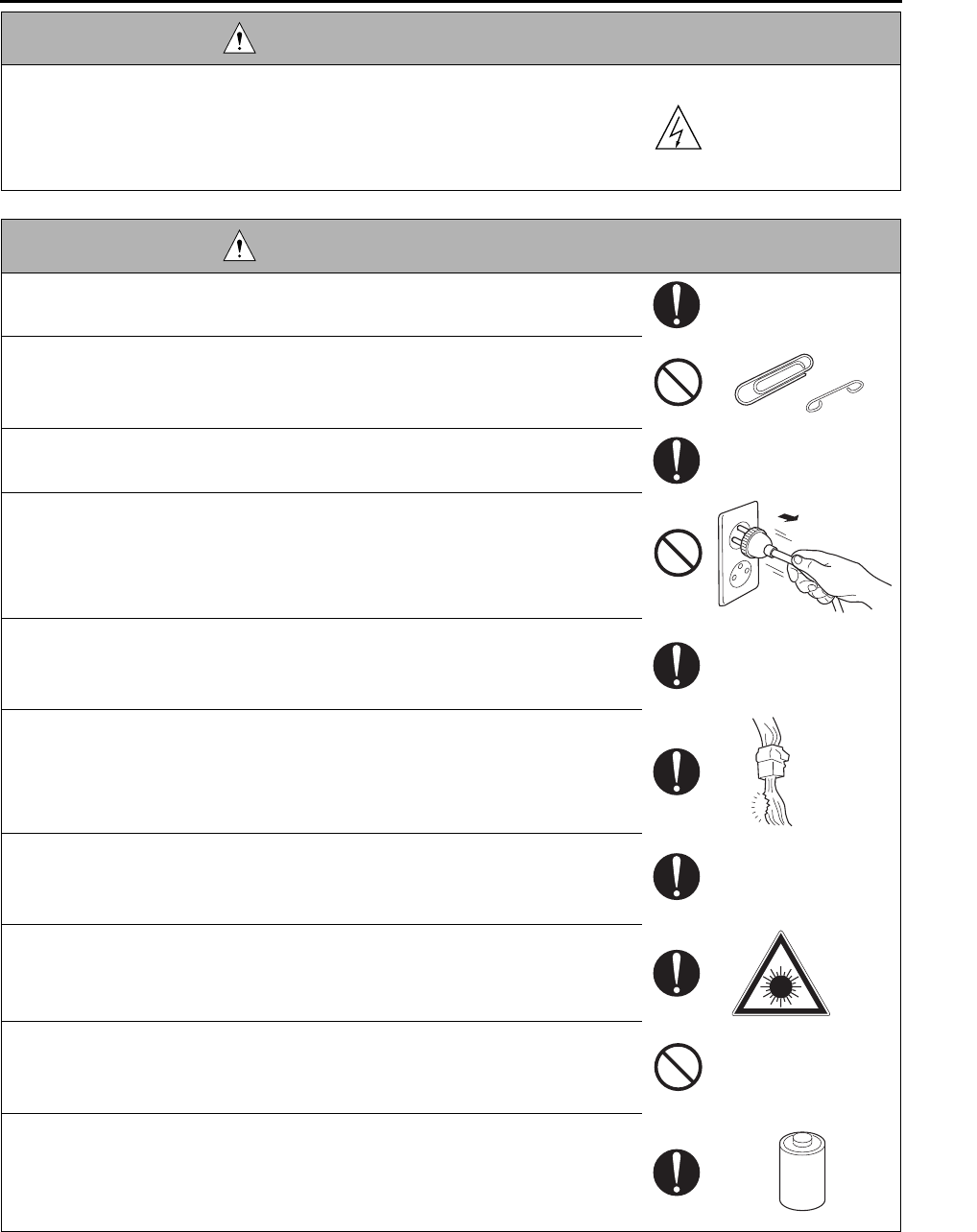
In this Service Manual, each of three expressions “ DANGER”, “ WARNING”, and “ CAUTION” is defined
as follows together with a symbol mark to be used in a limited meaning.
When servicing the copier, the relevant works (disassembling, reassembling, adjustment, repair, maintenance,
etc.) need to be conducted with utmost care.
Symbols used for safety and important warning items are defined as follows:
SAFETY AND IMPORTANT WARNING ITEMS
IMPORTANT NOTICE
DESCRIPTION ITEMS FOR DANGER, WARNING AND
CAUTION
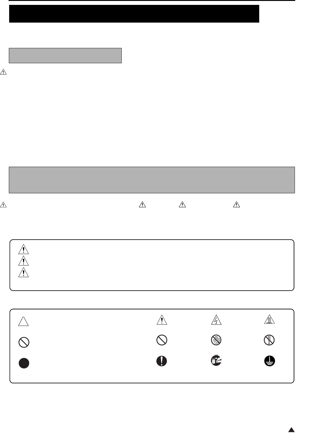
DANGER :Action having a high possibility of suffering death or serious injury
WARNING:Action having a possibility of suffering death or serious injury
CAUTION :Action having a possibility of suffering a slight wound, medium trouble, and
property damage
:Precaution when using the copier. General precaution Electric hazard High temperature
:Prohibition when using the copier. General prohibition Do not touch with wet hand Do not disassemble
:Direction when using the copier. General instruction Unplug Ground/Earth
SAFETY AND IMPORTANT WARNING ITEMS
S-2
1
[1] MODIFICATIONS NOT AUTHORIZED BY
KONICA MINOLTA BUSINESS TECHNOLOGIES, INC.
Konica Minolta brand copiers are renowned for their high reliability. This reliability is achieved through high-qual-
ity design and a solid service network.
Copier design is a highly complicated and delicate process where numerous mechanical, physical, and electrical
aspects have to be taken into consideration, with the aim of arriving at proper tolerances and safety factors. For
this reason, unauthorized modifications involve a high risk of degradation in performance and safety. Such mod-
ifications are therefore strictly prohibited. the points listed below are not exhaustive, but they illustrate the rea-
soning behind this policy.
SAFETY WARNINGS
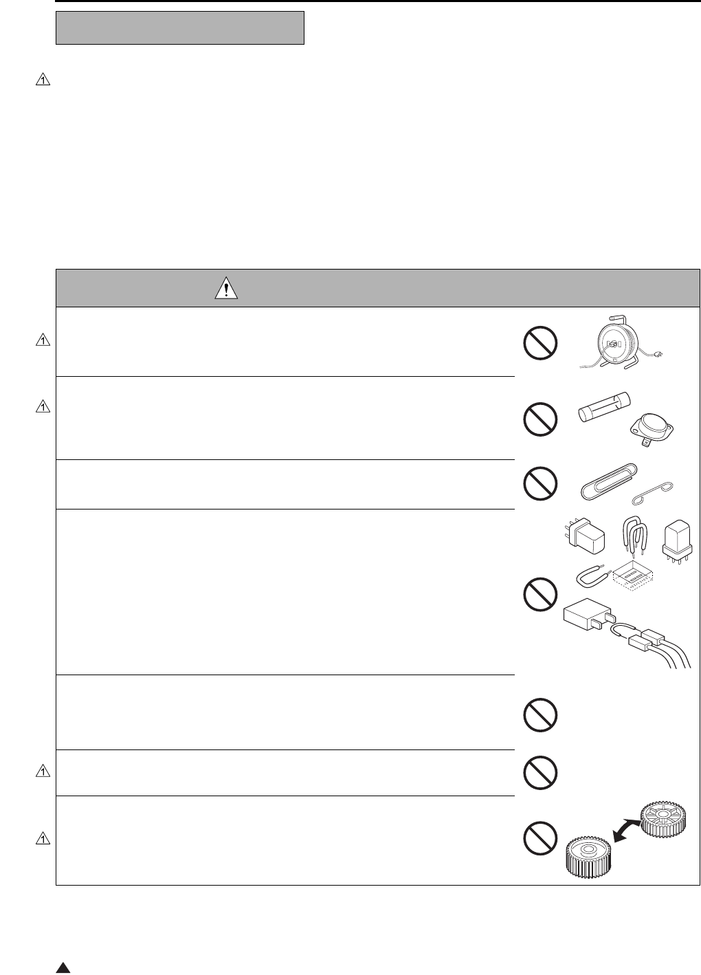
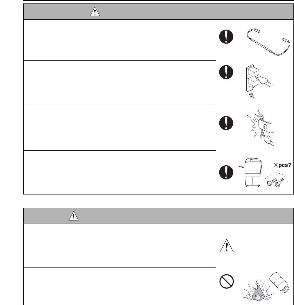
DANGER : PROHIBITED ACTIONS
• Using any cables or power cord not specified by KMBT.
• Using any fuse or thermostat not specified by KMBT. Safety will not be
assured, leading to a risk of fire and injury.
• Disabling fuse functions or bridging fuse terminals with wire, metal clips, sol-
der or similar object.
• Disabling relay functions (such as wedging paper between relay contacts)
• Disabling safety functions (interlocks, safety circuits, etc.) Safety will not be
assured, leading to a risk of fire and injury.
• Making any modification to the copier unless instructed by KMBT
• Using parts not specified by KMBT
SAFETY AND IMPORTANT WARNING ITEMS
S-3
1
[2] CHECKPOINTS WHEN PERFORMING ON-SITE SERVICE
Konica Minolta brand copiers are extensively tested before shipping, to ensure that all applicable safety stan-
dards are met, in order to protect the customer and customer engineer (hereafter called the CE) from the risk of
injury. However, in daily use, any electrical equipment may be subject to parts wear and eventual failure. In order
to maintain safety and reliability, the CE must perform regular safety checks.
1.Power Supply
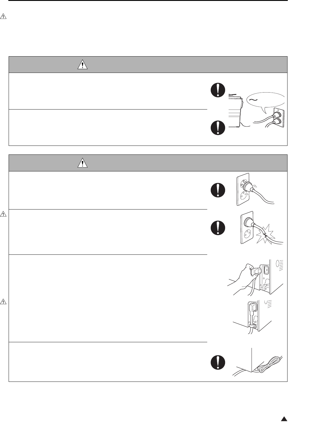
WARNING: Wall Outlet
• Check that mains voltage is as specified. Plug the power cord into the dedi-
cated wall outlet with a capacity greater than the maximum power consump-
tion.
If excessive current flows in the wall outlet, fire may result.
• If two or more power cords can be plugged into the wall outlet, the total load
must not exceed the rating of the wall outlet.
If excessive current flows in the wall outlet, fire may result.
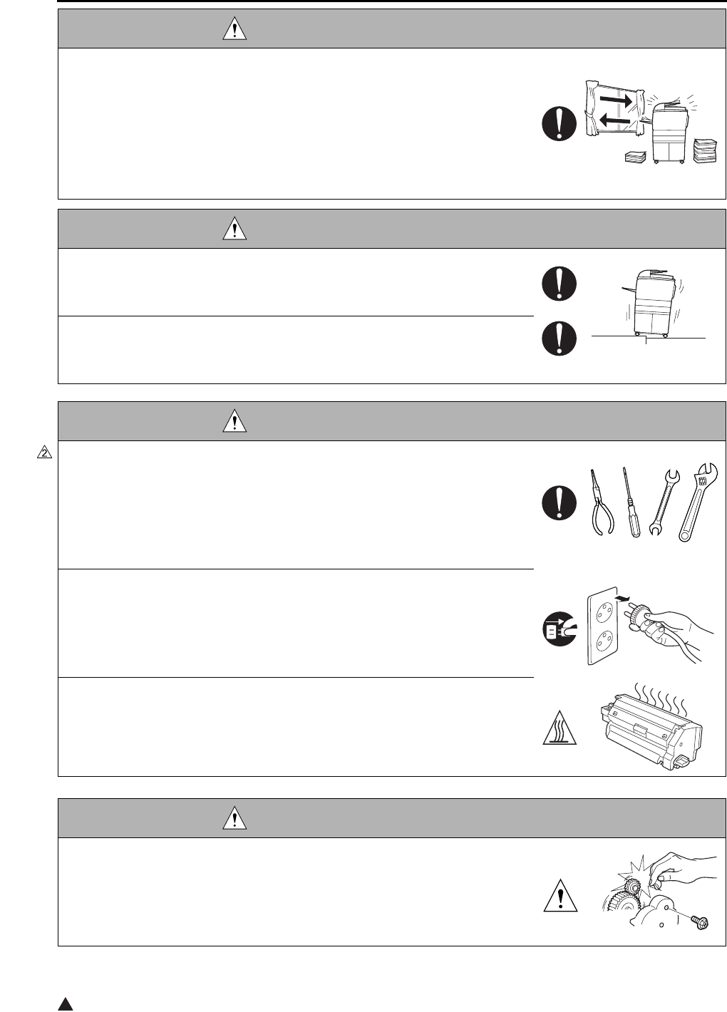
WARNING: Power Plug and Cord
• Make sure the power cord is plugged in the wall outlet securely.
Contact problems may lead to increased resistance, overheating, and the
risk of fire.
• Check whether the power cord is damaged. Check whether the sheath is
damaged.
If the power plug, cord, or sheath is damaged, replace with a new power
cord (with plugs on both ends) specified by KMBT. Using the damaged
power cord may result in fire or electric shock.
• When using the power cord (inlet type) that came with this copier, be sure to
observe the following precautions:
a. Make sure the copier-side power plug is securely inserted in the socket
on the rear panel of the copier.
Secure the cord with a fixture properly.
b. If the power cord or sheath is damaged, replace with a new power cord
(with plugs on both ends) specified by KMBT.
If the power cord (inlet type) is not connected to the copier securely, a
contact problem may lead to increased resistance, overheating, and risk
of fire.
• Check whether the power cord is not stepped on or pinched by a table and
so on.
Overheating may occur there, leading to a risk of fire.
kw

SAFETY AND IMPORTANT WARNING ITEMS
S-4
• Do not bundle or tie the power cord.
Overheating may occur there, leading to a risk of fire.
• Check whether dust is collected around the power plug and wall outlet.
Using the power plug and wall outlet without removing dust may result in
fire.
• Do not insert the power plug into the wall outlet with a wet hand.
The risk of electric shock exists.
• When unplugging the power cord, grasp the plug, not the cable.
The cable may be broken, leading to a risk of fire and electric shock.
WARNING: Wiring
• Never use multi-plug adapters to plug multiple power cords in the same out-
let.
If used, the risk of fire exists.
• When an extension cord is required, use a specified one.
Current that can flow in the extension cord is limited, so using a too long
extension cord may result in fire.
Do not use an extension cable reel with the cable taken up. Fire may
result.
WARNING: Ground Lead
• Check whether the copier is grounded properly.
If current leakage occurs in an ungrounded copier, you may suffer electric
shock while operating the copier. Connect the ground lead to one of the
following points:
a. Ground terminal of wall outlet
b. Ground terminal for which Class D work has been done
WARNING: Power Plug and Cord

SAFETY AND IMPORTANT WARNING ITEMS
S-5
2.Installation Requirements
• Pay attention to the point to which the ground lead is connected.
Connecting the ground lead to an improper point such as the points listed
below results in a risk of explosion and electric shock:
a. Gas pipe (A risk of explosion or fire exists.)
b. Lightning rod (A risk of electric shock or fire exists.)
c. Telephone line ground (A risk of electric shock or fire exists in the case
of lightning.)
d. Water pipe or faucet (It may include a plastic portion.)
WARNING: Prohibited Installation Place
• Do not place the copier near flammable materials such as curtains or volatile
materials that may catch fire.
A risk of fire exists.
• Do not place the copier in a place exposed to water such as rain water.
A risk of fire and electric shock exists.
WARNING: Nonoperational Handling
• When the copier is not used over an extended period of time (holidays, etc.),
switch it off and unplug the power cord.
Dust collected around the power plug and outlet may cause fire.
CAUTION: Temperature and Humidity
• Do not place the copier in a place exposed to direct sunlight or near a heat
source such as a heater.
A risk of degradation in copier performance or deformation exists.
Do not place the copier in a place exposed to cool wind.
Recommended temperature and humidity are as follows:
Temperature: 10°C to 30°C
Humidity: 10% to 80% (no dew condensation)
Avoid other environments as much as possible.
CAUTION: Ventilation
• Do not place the copier in a place where there is much dust, cigarette
smoke, or ammonia gas.
Place the copier in a well ventilated place to prevent machine problems
and image faults.
WARNING: Ground Lead
SAFETY AND IMPORTANT WARNING ITEMS
S-6
2
• The copier generates ozone gas during operation, but it is not sufficient to be
harmful to the human body.
If a bad smell of ozone is present in the following cases, ventilate the
room.
a. When the copier is used in a poorly ventilated room
b. When taking a lot of copies
c. When using multiple copiers at the same time
CAUTION: Vibration
• When installing the copier, read the Installation Guide thoroughly. Be sure to
install the copier in a level and sturdy place.
Constant vibration will cause problems.
• Be sure to lock the caster stoppers.
In the case of an earthquake and so on, the copier may slide, leading to a
injury.
CAUTION: Inspection before Servicing
• Before conducting an inspection, read all relevant documentation (service
manual, technical notices, etc.) and proceed with the inspection following the
prescribed procedure in safety clothes, using only the prescribed tools. Do
not make any adjustment not described in the documentation.
If the prescribed procedure or tool is not used, the copier may break and a
risk of injury or fire exists.
• Before conducting an inspection, be sure to disconnect the power plugs from
the copier and options.
When the power plug is inserted in the wall outlet, some units are still pow-
ered even if the POWER switch is turned OFF. A risk of electric shock
exists.
• The area around the fixing unit is hot.
You may get burnt.
DANGER: Work Performed with the Copier Powered
• Take every care when making adjustments or performing an operation check
with the copier powered.
If you make adjustments or perform an operation check with the external
cover detached, you may touch live or high-voltage parts or you may be
caught in moving gears or the timing belt, leading to a risk of injury.
CAUTION: Ventilation
SAFETY AND IMPORTANT WARNING ITEMS
S-7
• Take every care when servicing with the external cover detached.
High-voltage exists around the drum unit. A risk of electric shock exists.
WARNING: Safety Checkpoints
• Check the exterior and frame for edges, burrs, and other damages.
The user or CE may be injured.
• Do not allow any metal parts such as clips, staples, and screws to fall into the
copier.
They can short internal circuits and cause electric shock or fire.
• Check wiring for squeezing and any other damage.
Current can leak, leading to a risk of electric shock or fire.
• When disconnecting connectors, grasp the connector, not the cable.
(Specifically, connectors of the AC line and high-voltage parts)
Current can leak, leading to a risk of electric shock or fire.
• Carefully remove all toner remnants and dust from electrical parts and elec-
trode units such as a charging corona unit.
Current can leak, leading to a risk of copier trouble or fire.
• Check high-voltage cables and sheaths for any damage.
Current can leak, leading to a risk of electric shock or fire.
• Check electrode units such as a charging corona unit for deterioration and
sign of leakage.
Current can leak, leading to a risk of trouble or fire.
• Before disassembling or adjusting the write unit incorporating a laser, make
sure that the power cord has been disconnected.
The laser light can enter your eye, leading to a risk of loss of eyesight.
• Do not remove the cover of the write unit. Do not supply power with the write
unit shifted from the specified mounting position.
The laser light can enter your eye, leading to a risk of loss of eyesight.
• When replacing a lithium battery, replace it with a new lithium battery speci-
fied in the Parts Guide Manual. Dispose of the used lithium battery using the
method specified by local authority.
Improper replacement can cause explosion.
DANGER: Work Performed with the Copier Powered
SAFETY AND IMPORTANT WARNING ITEMS
S-8
WARNING: Safety Checkpoints
• After replacing a part to which AC voltage is applied (e.g., optical lamp and
fixing lamp), be sure to check the installation state.
A risk of fire exists.
• Check the interlock switch and actuator for loosening and check whether the
interlock functions properly.
If the interlock does not function, you may receive an electric shock or be
injured when you insert your hand in the copier (e.g., for clearing paper
jam).
• Make sure the wiring cannot come into contact with sharp edges, burrs, or
other pointed parts.
Current can leak, leading to a risk of electric shock or fire.
• Make sure that all screws, components, wiring, connectors, etc. that were
removed for safety check and maintenance have been reinstalled in the orig-
inal location. (Pay special attention to forgotten connectors, pinched cables,
forgotten screws, etc.)
A risk of copier trouble, electric shock, and fire exists.
DANGER: HANDLING OF SERVICE MATERIALS
• Toner and developer are not harmful substances, but care must be taken not
to breathe excessive amounts or let the substances come into contact with
eyes, etc. It may be stimulative.
If the substances get in the eye, rinse with plenty of water immediately.
When symptoms are noticeable, consult a physician.
• Never throw the used cartridge and toner into fire.
You may be burned due to dust explosion.
SAFETY AND IMPORTANT WARNING ITEMS
S-9
1
[3] MEASURES TO TAKE IN CASE OF AN ACCIDENT
1. If an accident has occurred, the distributor who has been notified first must immediately take emergency
measures to provide relief to affected persons and to prevent further damage.
2. If a report of a serious accident has been received from a customer, an on-site evaluation must be carried
out quickly and KMBT must be notified.
3. To determine the cause of the accident, conditions and materials must be recorded through direct on-site
checks, in accordance with instructions issued by KMBT.
4. For reports and measures concerning serious accidents, follow the regulations given in “Serious Accident
Report/Follow-up Procedures”.
[4] CONCLUSION
1. Safety of users and customer engineers depends highly on accurate maintenance and administration.
Therefore, safety can be maintained by the appropriate daily service work conducted by the customer
engineer.
2. When performing service, each copier on the site must be tested for safety. The customer engineer must
verify the safety of parts and ensure appropriate management of the equipment.
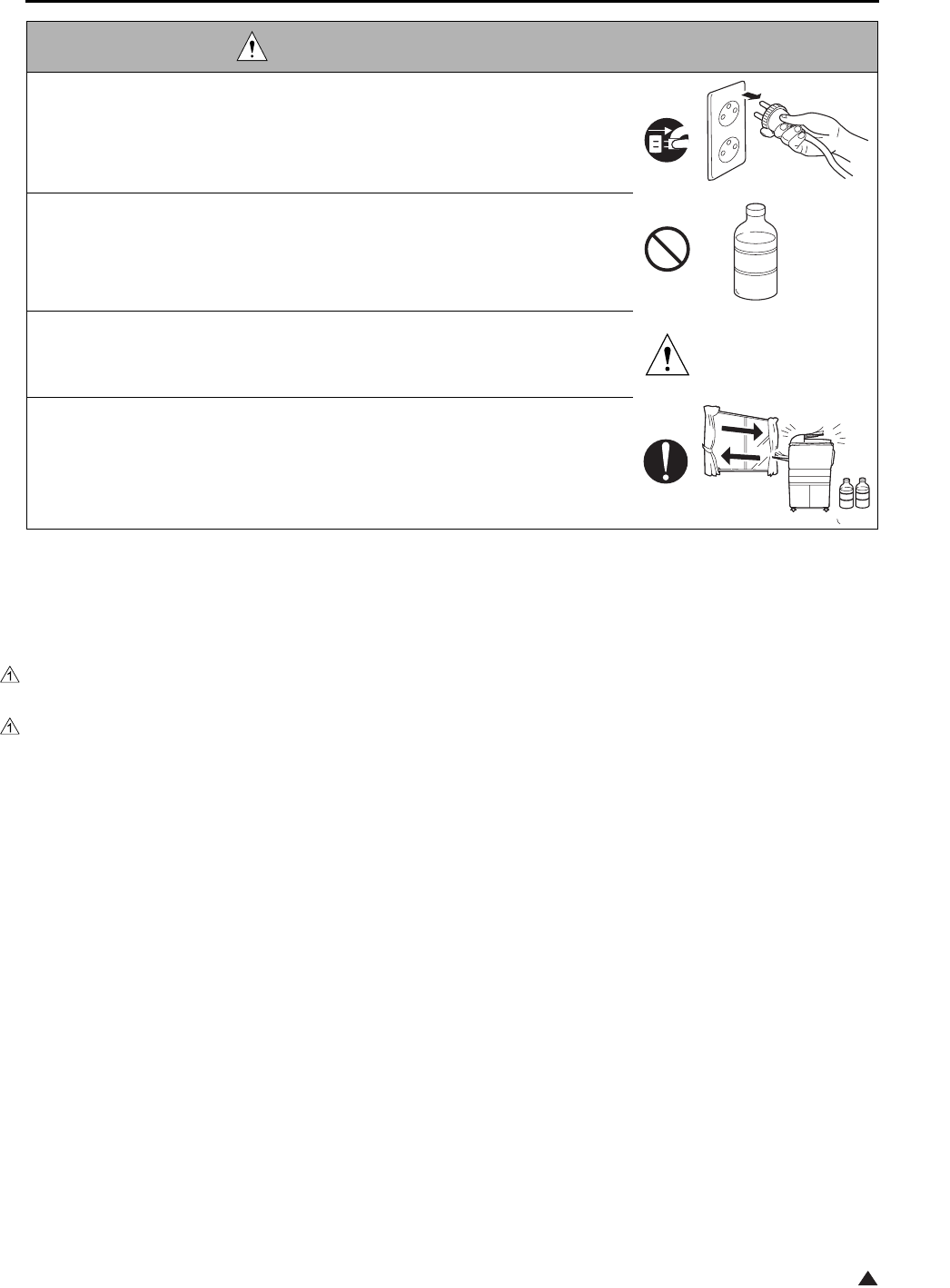
DANGER : HANDLING OF SERVICE MATERIALS
• Unplug the power cord from the wall outlet.
Drum cleaner (isopropyl alcohol) and roller cleaner (acetone-based) are
highly flammable and must be handled with care. A risk of fire exists.
• Do not replace the cover or turn the copier ON before any solvent remnants
on the cleaned parts have fully evaporated.
A risk of fire exists.
• Use only a small amount of cleaner at a time and take care not to spill any
liquid. If this happens, immediately wipe it off.
A risk of fire exists.
• When using any solvent, ventilate the room well.
Breathing large quantities of organic solvents can lead to discomfort.

SAFETY AND IMPORTANT WARNING ITEMS
S-10
The Center for Devices and Radiological Health (CDRH) of the U.S. Food and Drug Administration implemented
regulations for laser products manufactured since August 1, 1976. Compliance is mandatory for products mar-
keted in the United States.
This copier is certified as a “Class 1” laser product under the U.S.
Department of Health and Human Services (DHHS) Radiation Performance Standard according to the Radiation
Control for Health and Safety Act of 1968. Since radiation emitted inside this copier is completely confined within
protective housings and external covers, the laser beam cannot escape during any phase of normal user opera-
tion.
SAFETY INFORMATION
IMPORTANT INFORMATION
SAFETY AND IMPORTANT WARNING ITEMS
S-11
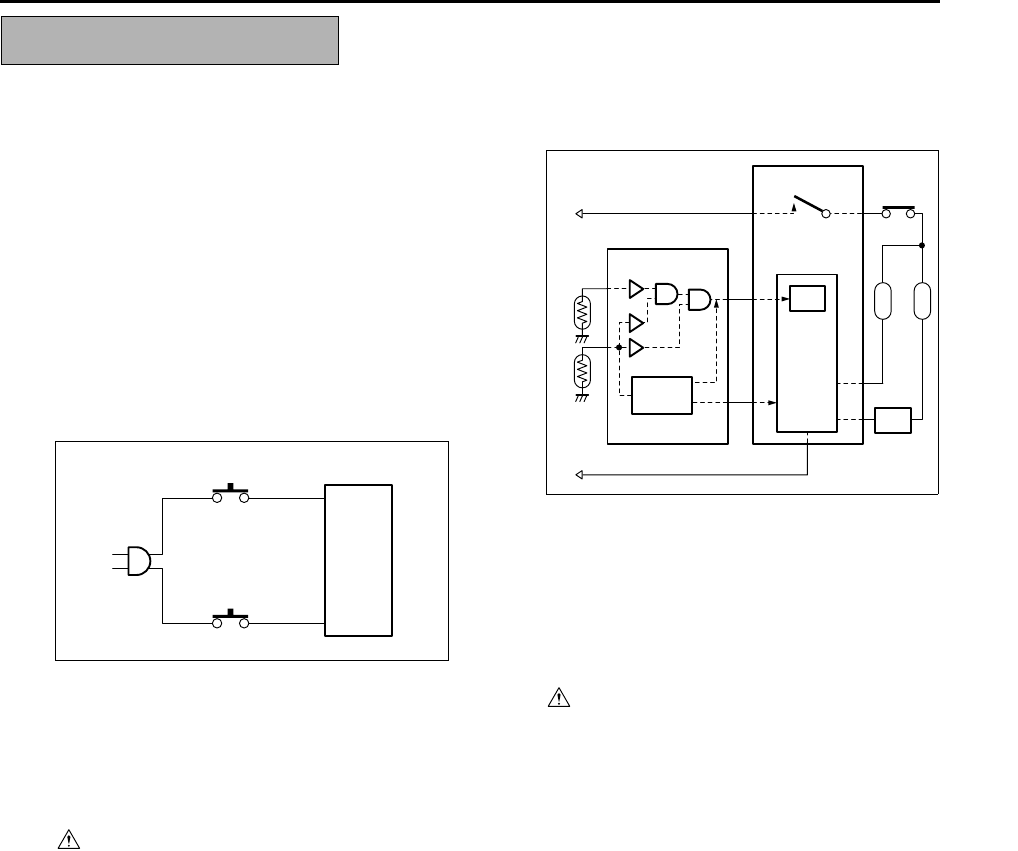
This machine is provided with the following safety circuits
to prevent machine faults from resulting in serious acci-
dents.
[1] Overall protection circuit
[2] L2 and L3 (fixing heater lamp/1, /2) overheat-
ing prevention circuit
These safety circuits are described below to provide
the service engineer with a renewed awareness of
them in order to prevent servicing errors that may
impair their functions.
[1] Overall protection circuit
1. Protection by CBR1 and CBR2 (circuit
breaker/1, /2)
CBR1 and CBR2 interrupt the AC line instanta-
neously when an excessive current flows due
to a short in the AC line.
CAUTION:
The CBR1 and CBR2 functions must not
be deactivated under any circumstances.
[2] L2 and L3 (fixing heater lamp/1, /2)
overheating prevention circuit
1. Protection by software
The output voltage from TH1, TH2 (fixing tem-
perature sensor/1, /2) is read by the CPU. If
this voltage is abnormal, L2 (fixing heater
lamp/1), L3 (fixing heater lamp/2) and RL1
(main relay) are turned OFF.
CAUTION:
The RL1 function must not be deactivated
under any circumstances.
SAFETY CIRCUITS
DCPS
CBR1
CBR2
DCPS
CB
L3
L2
AC driver
section
RL1
FCB
Control
section
TH1 TH2
RL1 TS

SAFETY AND IMPORTANT WARNING ITEMS
S-12
2
2. Protection by the hardware circuit
The output voltages from TH1, TH2 (fixing tem-
perature sensor/1, /2) are compared with the
abnormality judgment reference value in the
comparator circuit. If the output voltage from
TH1 or TH2 exceeds the reference value, L2
(fixing heater lamp/1), L3 (fixing heater lamp/2)
and RL1 (main relay) are turned OFF in hard-
ware means.
CAUTION:
Periodically check the TH1, TH2 face
contacting the roller, and replace TH2 if
any abnormality is detected.
The RL1 function must not be deactivated
under any circumstances.
3. Protection by TS (thermostat)
When the fixing heat roller exceeds the speci-
fied value, TSs (thermostats) are turned OFF,
thus interrupting the power to L2 (fixing heater
lamp/1), and L3 (fixing heater lamp/2) directly.
CAUTION:
Do not use any other electrical conductor
in place of TS1 and TS2.
SAFETY AND IMPORTANT WARNING ITEMS
S-13 2
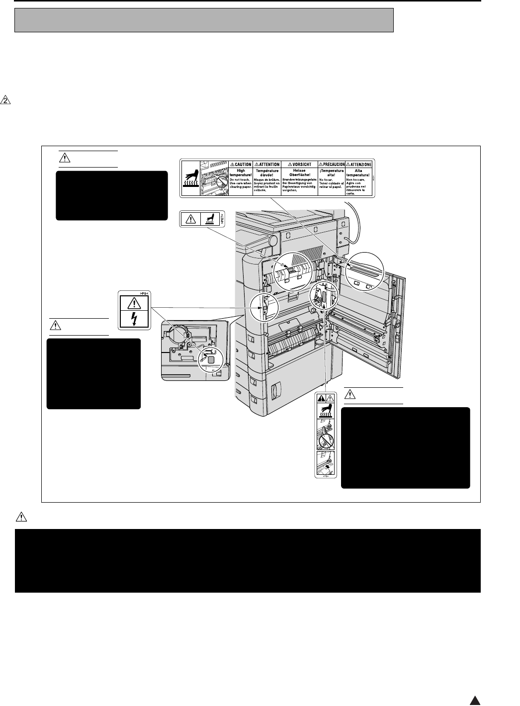
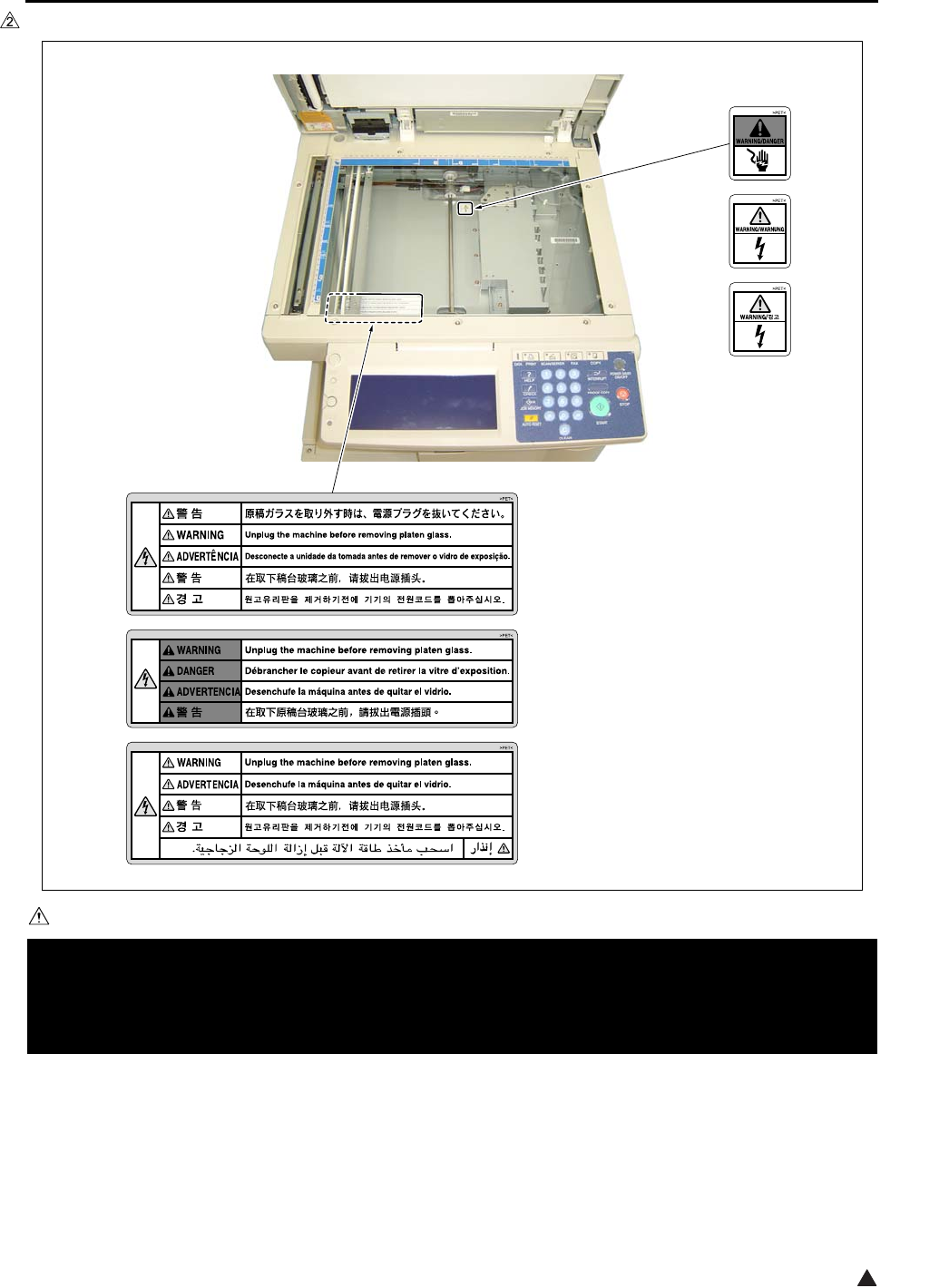
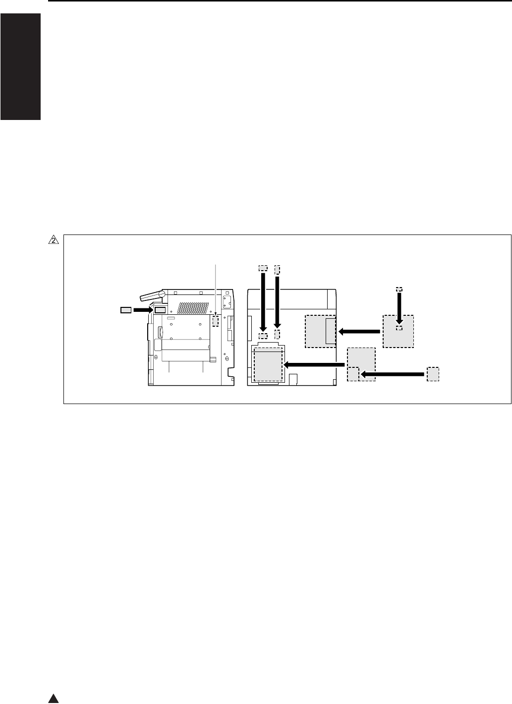
Caution labels shown below are attached in some areas on/in the machine.
When accessing these areas for maintenance, repair, or adjustment, special care should be taken to avoid burns
and electric shock.
[1] Main body
1. Right side
<7145>
CAUTION
INDICATION OF WARNING ON THE MACHINE
You may be burned or injured if you touch any area that you are advised by any caution label to keep your-
self away from.
Do not remove caution labels. If any caution label has come off or soiled and therefore the caution cannot
be read, contact our Service Office.
7322sf001e
CAUTION
The fixing unit is very hot.
To avoid getting burned
DO NOT TOUCH.
CAUTION
This area generates
high voltage.
If touched, electrical
shock may occur.
DO NOT TOUCH! CAUTION
The roller shaft on the inside
of the cover is very hot.
To avoid getting burned DO
NOT TOUCH.
If the cover comes off, return
it to its original position.
(Inside of the main
body right side door)
(Inside of the main
body front door)
SAFETY AND IMPORTANT WARNING ITEMS
S-14
2
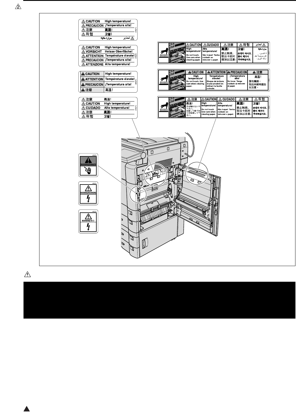
<7235/7228/7222>
CAUTION
You may be burned or injured if you touch any area that you are advised by any caution label to keep your-
self away from.
Do not remove caution labels. If any caution label has come off or soiled and therefore the caution cannot
be read, contact our Service Office.
7322sf002e

SAFETY AND IMPORTANT WARNING ITEMS
S-15 2
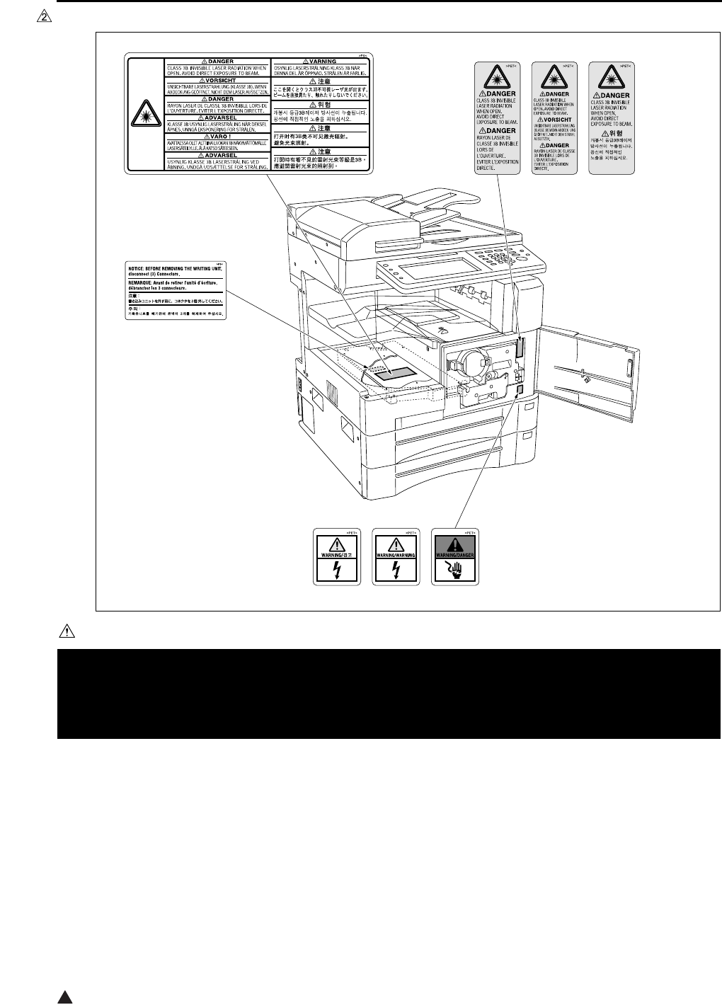
2. Front side
<7145>
CAUTION
You may be burned or injured if you touch any area that you are advised by any caution label to keep your-
self away from.
Do not remove caution labels. If any caution label has come off or soiled and therefore the caution cannot
be read, contact our Service Office.
7322sf003e
SAFETY AND IMPORTANT WARNING ITEMS
S-16
2
<7235/7228/7222>
CAUTION
You may be burned or injured if you touch any area that you are advised by any caution label to keep your-
self away from.
Do not remove caution labels. If any caution label has come off or soiled and therefore the caution cannot
be read, contact our Service Office.
7322sf004e
SAFETY AND IMPORTANT WARNING ITEMS
S-17 2
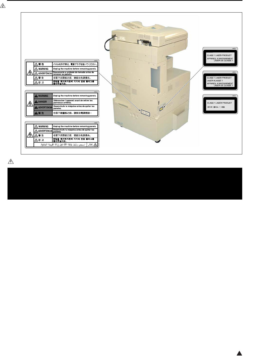
3. Rear/Left side (7235/7228/7222 only)
CAUTION
You may be burned or injured if you touch any area that you are advised by any caution label to keep your-
self away from.
Do not remove caution labels. If any caution label has come off or soiled and therefore the caution cannot
be read, contact our Service Office.
7322sf005e

SAFETY AND IMPORTANT WARNING ITEMS
S-18
2
4. Scanner section
<7145>
CAUTION
You may be burned or injured if you touch any area that you are advised by any caution label to keep your-
self away from.
Do not remove caution labels. If any caution label has come off or soiled and therefore the caution cannot
be read, contact our Service Office.
7322sf006
SAFETY AND IMPORTANT WARNING ITEMS
S-19 2
<7235/7228/7222>
CAUTION
You may be burned or injured if you touch any area that you are advised by any caution label to keep your-
self away from.
Do not remove caution labels. If any caution label has come off or soiled and therefore the caution cannot
be read, contact our Service Office.
7322sf007e

SAFETY AND IMPORTANT WARNING ITEMS
S-20
2
[2] FS-113
[3] FS-114
CAUTION
You may be burned or injured if you touch any area that you are advised by any caution label to keep your-
self away from.
Do not remove caution labels. If any caution label has come off or soiled and therefore the caution cannot
be read, contact our Service Office.
7322sf009
CAUTION
This area is very hot.
To avoid getting
burned DO NOT
TOUCH.
CAUTION
To avoid injury, DO NOT put your hand on the top
of the printed sheets. Be sure to hold both sides
of the printed sheets when removing them, and
DO NOT leave your hand on the printed sheets
while the primary (main) tray goes up.
(Inside of the Finisher)
FS-113 Finisher
7322sf010
FS-114 Finisher
List of major differences between the 7145, 7235, 7228 and 7222
12
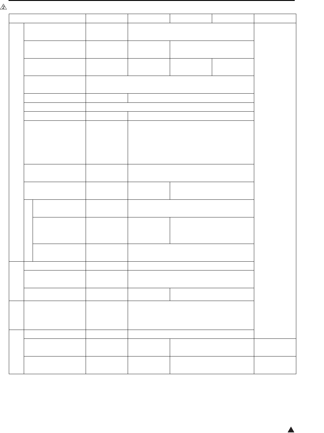
List of major differences between the 7145, 7235, 7228 and 7222
Classification 7145 7235 7228 7222 Reason
Specifications
Warmup time Less than
30 sec. Less than 19 sec.
Change of
specifications
First copy out time
(8.5x11)
Less than
3.8 sec.
Less than
4.3 sec. Less than 4.9 sec.
Continuous copy
speed (8.5x11)
45 sheets/min. 35 sheets/min. 28 sheets/min.
22 sheets/min.
Maximum E-RDH
memory 320MB
DF Standard Optional
ADU Standard
Paper exit tray
Optional
Standard
Machine dimensions
(with DF and DB)
23.2in (W)
x
23.4in (D)
x
42.6in (H)
23.4in (W) x 25.8in (D) x 44.6in (H)
Maintenance
Once every
120,000 copies
Once every 100,000 copies
Materials
Developer Exclusively
for 7145 Exclusively for 7235/7228/7222
Toner Exclusively
for 7145
Exclusively for
7235 (Common
to 7135)
Exclusively for 7228/7222
(Common to 7022/7120/7135)
Drum Exclusively
for 7145 Exclusively for 7235/7228/7222
Drive section
Flywheel f 103mm f 132mm
Developing sleeve
drive
Developing
motor Main motor
Vibration insulator Not provided Provided Not provided
Scanner
section
Scanner drive board Provided Not provided
Write section
Laser 2 beams 1 beam
Number of rotations
of polygon motor 27,165rpm 38,976rpm 33,070rpm Change of
CPM
Polygon cooling Not provided Provided Not provided Change of
specifications
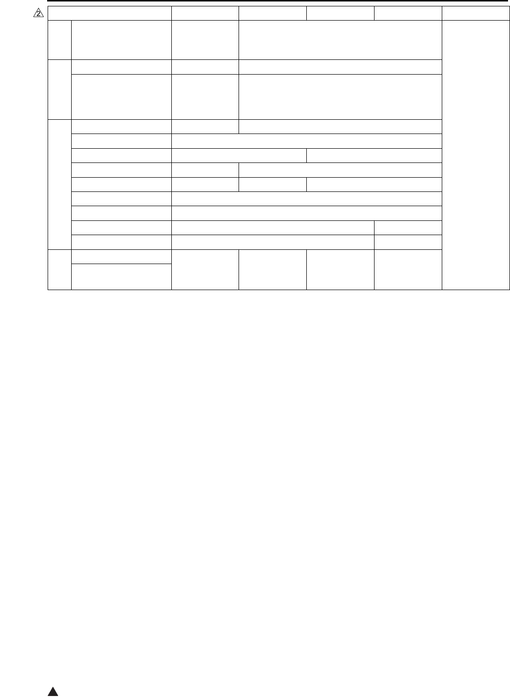
List of major differences between the 7145, 7235, 7228 and 7222
2
2
Fixing
section
Fixing unit Exclusively
for 7145 Exclusively for 7235/7228/7222
Change of
specifications
ADU/Paper
exit section
Decurler roller Provided Not provided
ADU drive board Not provided Provided
Electrical parts
Developing motor Provided Not provided
ADU motor Provided
Fixing cooling fan Provided Not provided
Internal cooling fan/2 Provided Not provided
Polygon cooling fan Not provided Provided Not provided
ADU gate solenoid Provided
ADU sensor Provided
Timing sensor/U Provided Not provided
Timing sensor/L Provided Not provided
Control
Overall control Exclusively
for 7145
Exclusively
for 7235
Exclusively
for 7228
Exclusively
for 7222
Image control
Classification 7145 7235 7228 7222 Reason

List of options corresponding to the 7145/7235/7228/7222
32
List of options corresponding to the 7145/7235/7228/7222
Optional 7145 7235 7228 7222
RADF DF-318 Standard Not corresponding
DF-320
Not corresponding
Corresponding
Finisher FS-112 Corresponding Not corresponding
FT-107
FS-113
Corresponding
RU-101
FS-114
BK-114
PK-114
SK-114
Paper exit tray ET-101 Corresponding Corresponding*1
Inner tray IT-101 Corresponding
Desk DK-110
Not corresponding
Corresponding
DB DB-211
CorrespondingDB-411
LCT LT-203
ADU AD-307 Standard
Post script PS-344 Corresponding Not corresponding
PS-346
Not corresponding
Corresponding
Printer
controller
IP-432 Corresponding Not corresponding
IP-424
Not corresponding
Corresponding
FAX controll
board
FK-102 Type-A
Corresponding Not corresponding
FK-103
Not corresponding
Corresponding
2 lines
expansion kit
FL-102 Corresponding Not corresponding
FL-103
Not corresponding
Corresponding
Hard disk HD-103 Type-A
Corresponding
Total counter Standard Corresponding
Key counter Corresponding
*1 A paper exit tray is provided as standard equipment that is different from ET-101. When ET-101 is pro-
vided, it is integrated into the main body as seen from the point of design.

List of options corresponding to the 7145/7235/7228/7222
4
Blank Page
OUTLINE OF SYSTEM
1-1
I OUTLINE
2
IOUTLINE
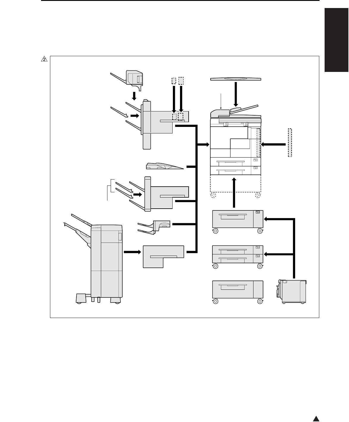
1. OUTLINE OF SYSTEM
[18][1]
[2]
[3]
[17]
[4]
[5]
[6] [7]
[8]
[13]
[9]
[12]
[16]
[11]
[10]
[14] [19][15]
7322ma1001
OUTLINE OF SYSTEM
1-2
I OUTLINE
2
*1 As a standard equipment, the 7235/7228/7222 are provided with a paper exit tray that is different from
the one with which the ET-101 is equipped.
[1] Main body [10]
RADF (DF-318: 7145 provided as a standard equipment)
(DF-320: 7235/7228/7222)[2] LCT (LT-203)
[3] LCT DB (DB-411) [11] Paper exit tray (ET-101)*1
[4] 2-Tray DB (DB-211) [12] Finisher (FS-114)
[5] Conveyance unit (RU-101) [13] Additional tray (BK-114)
[6] Finisher (FS-113) [14] Punch kit (PK-114)
[7] Inner tray (IT-101) [15] Crease unit (included in SK-114)
[8] Finisher tray (FT-107: FS-112) [16] Saddle unit (SK-114)
[9] Finisher (FS-112: 7145 only) [17] Desk (DK-110: 7235/7228/7222 only)
[18] ADU (provided as a standard equipment)
[19] Platen cover (CV-109: 7235/7228/7222 only)
[1] Postscript (PS-344: 7145)
(PS-346: 7235/7228/7222)
[6]
[7]
[8]
[9]
Hard disk (HD-103 Type-A)
Total counter
(7145 provided as standard equipment)
(In the case of the 7235/7228/7222, ship-
ments only to the United States are pro-
vided with the total counter.)
Key counter
Expansion memory for the printer controller
(Not displayed here. For details, see the
Service Manual of the controller.)
[2]
[3]
Printer controller (IP-432: 7145)
(IP-424: 7235/7228/7222)
2 line expansion kit (shipments only to the
United States and
Oceania)
(FL-102:FK-102 Type-A)
(FL-103:FK-103)
[4] Fax control board(FK-102 Type-A: 7145)
(FK-103: 7235/7228/7222)
[5]
E-RDH expansion memory (MU-404: 64MB/MU-405: 128MB)
[1]
[2]
[3]
[4]
[5][6]
[7]
[8]
7145ma1020

PRODUCT SPECIFICATIONS
1-3
I OUTLINE
2
2. PRODUCT SPECIFICATIONS
A. Type
Type: Semi-console type (7145)
Desk-top type (7235/7228/7222)
Copying method: Indirect electrostatic method
Original table: Fixed
Original alignment: Left rear standard
Photosensitive material: OPC
Sensitizing method: Laser writing
Paper feed trays: Two trays (500 sheets x 2, 80g/m2 or 20lbs)
Multisheet bypass tray (50 sheets, 80g/m2)
DB-211 (500 sheets x 2, 80g/m2 or 20lbs) *1
DB-411 (1500 sheets, 80g/m2 or 20lbs) *1
LT-203 (2000 sheets, 80g/m2 or 20lbs) *1
*1 Optional
B. Functions
Original: Sheet, book, solid object (Thickness: up to 1.2in. Weight: up to 15lbs)
Maximum original size: A3, or 11 x 17
Copy size (for metric area):
Tray 1: B4, A4, A4R, B5, B5R, A5R, 8.5 x 14, 8.5 x 11, 8.5 x 11R, 5.5 x 8.5R, F4
Tray 2: A3, B4, A4, A4R, B5, B5R, A5R, 11 x 17, 8.5 x 11, 8.5 x 11R, F4
Bypass tray: A3, B4, A4, A4R, B5, B5R, A5R, B6R, 8.5 x 11R (7145 only),
8.5 x 11 (except the 7145), F4 (except the 7145)
ADU: A3, B4, A4, A4R, B5, B5R, A5R, 11 x 17, 8.5 x 11, 8.5 x 11R, 8.5 x 14, 5.5
x 8.5R, F4
Copy size (for inch area):
Tray 1: 8.5 x 14, 8.5 x 11, 8.5 x 11R, 5.5 x 8.5R, F4, B4R (7145 only), A4, A4R,
B5, A5R
Tray 2: 11 x 17, 8.5 x 14, 8.5 x 11, 8.5 x 11R, 5.5 x 8.5R, F4, A3, A4, A4R, A5R
Bypass tray: 11 x 17, 8.5 x 14, 8.5 x 11, 8.5 x 11R, 5.5 x 8.5R, A4
ADU: 11 x 17, 8.5 x 14, 8.5 x 11, 8.5 x 11R, 5.5 x 8.5R, A3, B4 (7145 only), A4,
A4R, B5, A5R, F4
Magnification:
Fixed magnification (for metric area):
x 1.00, x 1.41, x 1.22, x 1.15, x 0.86, x 0.82, x 0.71
Fixed magnification (for inch area):
x 1.00, x 2.00, x 1.55, x 1.29, x 0.77, x 0.65, x 0.50
Special ratio: Three kinds
Zoom magnification: x 0.25 to x 4.00 (at 1% step)
Vertical magnification: x 0.25 to x 4.00 (at 1% step)
Horizontal magnification: x 0.25 to x 4.00 (at 1% step)

PRODUCT SPECIFICATIONS
1-4
I OUTLINE
2
Warm-up time: Less than 30 sec. (7145)
(at temperature of 68°F, Less than 19 sec. (7235/7228/7222)
at rated voltage)
First copy out time: Less than 3.8 sec. (7145)
Less than 4.3 sec. (7235)
Less than 4.9 sec. (7228/7222)
* platen mode, manual density, life size, tray 1, paper exit with face down,
A4 or 8.5 x 11
Continuous copy speed: 45 copies/min. (7145)
(A4 or 8.5 x 11, 35 copies/min. (7235)
in memory copy) 28 copies/min. (7228)
22 copies/min. (7222)
Continuous copy count: Up to 999
No. of sheets loadable
on the paper exit tray: Up to 100 (8.5x11)
Copy density selection: AE, manual (9 steps), arbitrary density (2 modes)
Resolution:
Scan: 600 dpi x 600 dpi
Write: 600 dpi x 600 dpi
ERDH memory *1: Standard 64MB, Maximum 320MB
Interface section: Serial port (USB TypeB), Serial port (RS-232C), RJ45 Ethernet connector,
Parallel port (IEEE1284 (Compatible, Nible, ECP))
Network section: Ethernet frame type: IEEE 802.3/802.3/Ethernet II/
IEEE 802.3 SNAP
Connecting type: 10 Base-T/100 Base-TX
Corresponding protocol: TCP/IP (BOOTP, ARP, ICMP, DHCP,
SNMP, HTTP, SMTP, POP3, FTP, IPP),
IPX/SPX, AppleTalk (EtherTalk),
Corresponding OS: Novell NetWare (3.x, 4.x, 5.x), Microsoft
Windows 95/98/Me, Microsoft Windows
NT4.0/2000/XP, Mac OS8.x and later,
Mac OS10.2.5
Multi-protocol: Automatic discrimination
Corresponding printing method: Peer-to-Peer (TCP/IP), LPD/LPR (TCP/
IP), PServer (IPX/SPX), RPrinter (IPX,
SPX), AppleTalk (EtherTalk)
General purpose utility: Web browser (Internet Explorer,
Netscape Navigator)
Status indicator LED: Green LED and orange LED, one for
each
*1 Since the standard 64MB memory is packaged on the board, it is not possible to replace it with a new
one.
Only one slot is provided for expansion. It can be installed with MU-404 (64MB), MU-405 (128MB), or
256MB (commercially available).
For 256MB (commercially available), be sure to use those of make and model No. specified separately.

PRODUCT SPECIFICATIONS
1-5
I OUTLINE
2
Number of originals to be stored:More than 140 sheets under the following conditions:
Original: Konica standard chart
Density: Manual 5
Mode: Character/photograph
Memory capacity: 64MB (provided only as standard)
Job: Job in mode with page memory not used
C. Copy Paper
Plain paper: 60g/m2 or 17lbs to 105g/m2 or 28lbs, high-quality paper
Special paper *1 Label paper, OHP film, blueprint-master paper, 50g/m2 or 13lbs to 59g/m2
or 16lbs high-quality paper (thin), 106g/m2 or 28lbs to 130g/m2 or 35lbs
high-quality paper (thick1), 131g/m2 or 35lbs to 160g/m2 or 43lbs high-
quality paper (thick2 *2)
*1 With bypass feed method, paper should be fed one sheet at a time. Double sided copy not allowed.
*2 Only bypass feed.
D. Machine Data
Power source: 230VAC –14% to 10.6% 50Hz/60Hz
120VAC –14% to 6% 60Hz
Power consumption: Maximum 1500W or less (fully optional)
Weight: Approximately 183lbs (with DF provided)
Dimensions: 7145: 23.2in (W) x 23.4in (D) x 42.6in (H) (with DF + DB)
7235/7228/7222: 23.4in (W) x 25.8in (D) x 44.6in (H) (with DF + DB)
E. Maintenance
Maintenance: Once every 120,000 copies (7145)
Once every 100,000 copies (7235/7228/7222)
F. Consumables
Developer: Exclusively for 7145
Exclusively for 7235/7228/7222
Toner: Exclusively for 7145
Exclusively for 7235 (Common to 7135)
Exclusively for 7228/7222 (Common to 7022/7120/7130)
Drum: Exclusively for 7145 (φ 60)
Exclusively for 7235/7228/7222 (φ 60)

PRODUCT SPECIFICATIONS
1-6
I OUTLINE
G. Operating Environment
Temperature: 10°C to 30°C (50°F to 86°F)
Humidity: 10% RH to 80% RH
Note:
• The information herein may be subject to change for improvement without notice.
CENTER CROSS SECTION
1-7
I OUTLINE
2
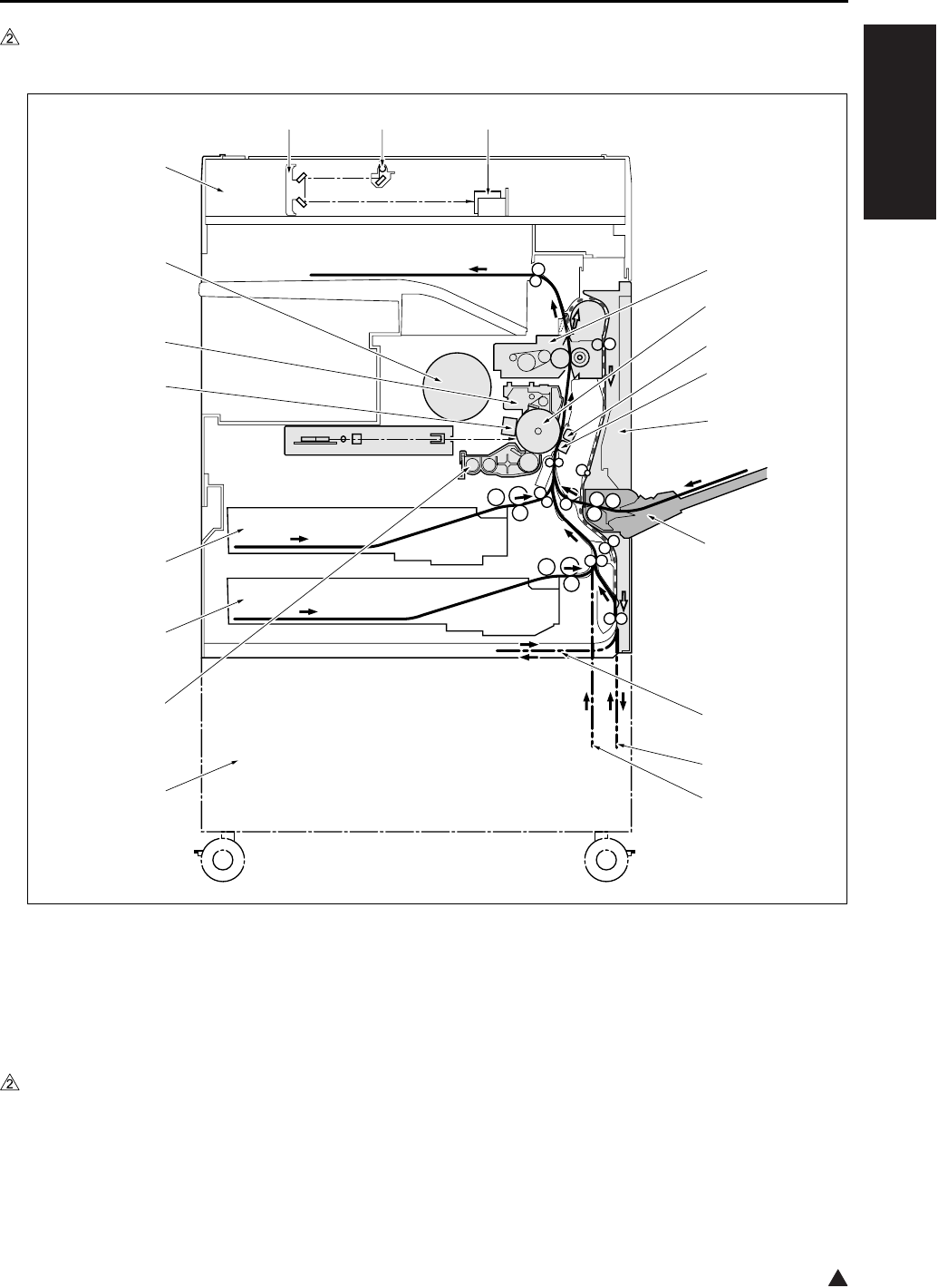
3. CENTER CROSS SECTION
[1] Fixing unit [10] DB
[2] Drum unit [11] Developing unit
[3] Separation corona unit [12] Tray 2
[4] Transfer corona unit [13] Tray 1
[5] ADU unit [14] Charging corona unit
[6] Bypass tray [15] Cleaning/toner recycling unit
[7] Paper feed path for making a double-sided
copy (DB unprovided)
[16]
[17]
Toner bottle
Scanner unit
[8] Paper feed path for making a double-sided
copy (DB provided)
[18]
[19]
V-mirror unit
Exposure unit
[9] DB paper feed path [20] CCD unit
7322ma1002
[1]
[2]
[3]
[4]
[5]
[6]
[8]
[7]
[9]
[10]
[11]
[12]
[13]
[14]
[15]
[16]
[17]
[18] [19] [20]
DRIVE SYSTEM DIAGRAM
1-8
I OUTLINE
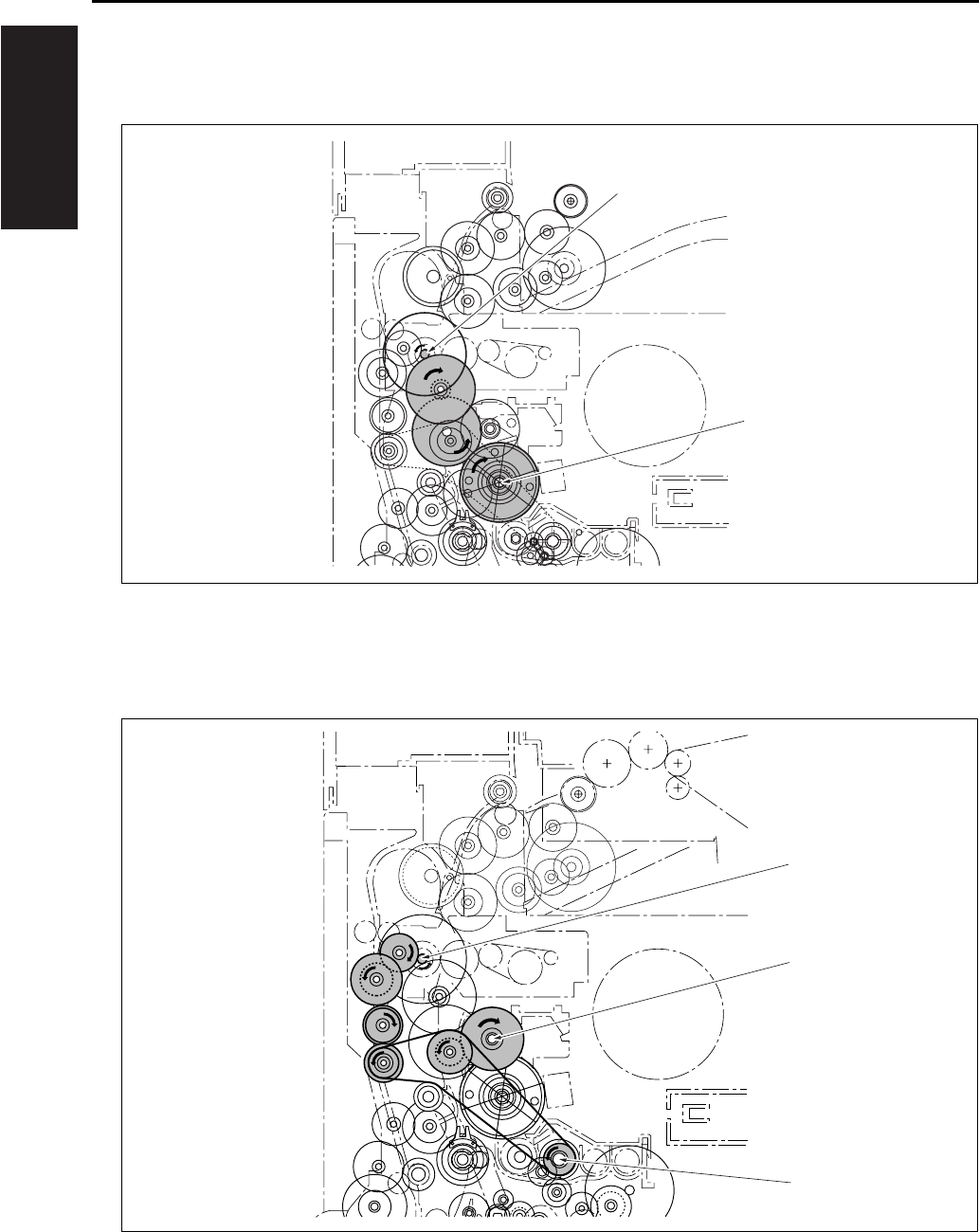
4. DRIVE SYSTEM DIAGRAM
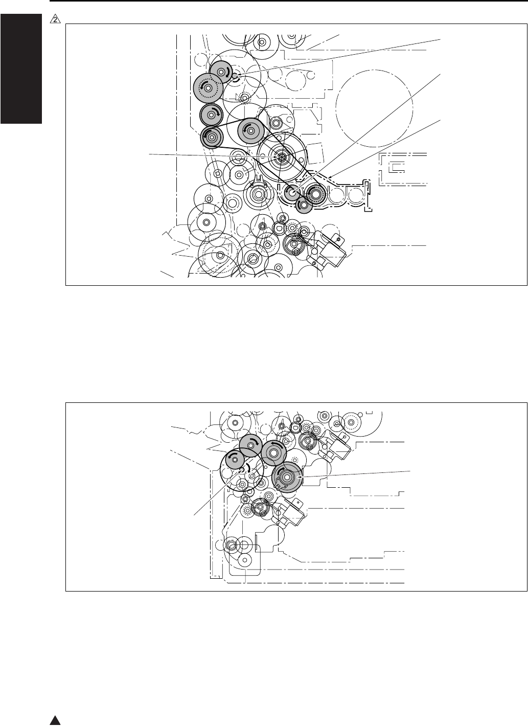
4.1 Drum Drive
4.2 Cleaning/Developer Agitation Drive
[1] M1 (Main motor) [2] Drum drive shaft
[1] M1 (Main motor) [3] Developer agitation drive
[2] Cleaning/toner recycling unit drive
[1]
[2]
[1]
[2]
[3]
DRIVE SYSTEM DIAGRAM
1-9
I OUTLINE
2
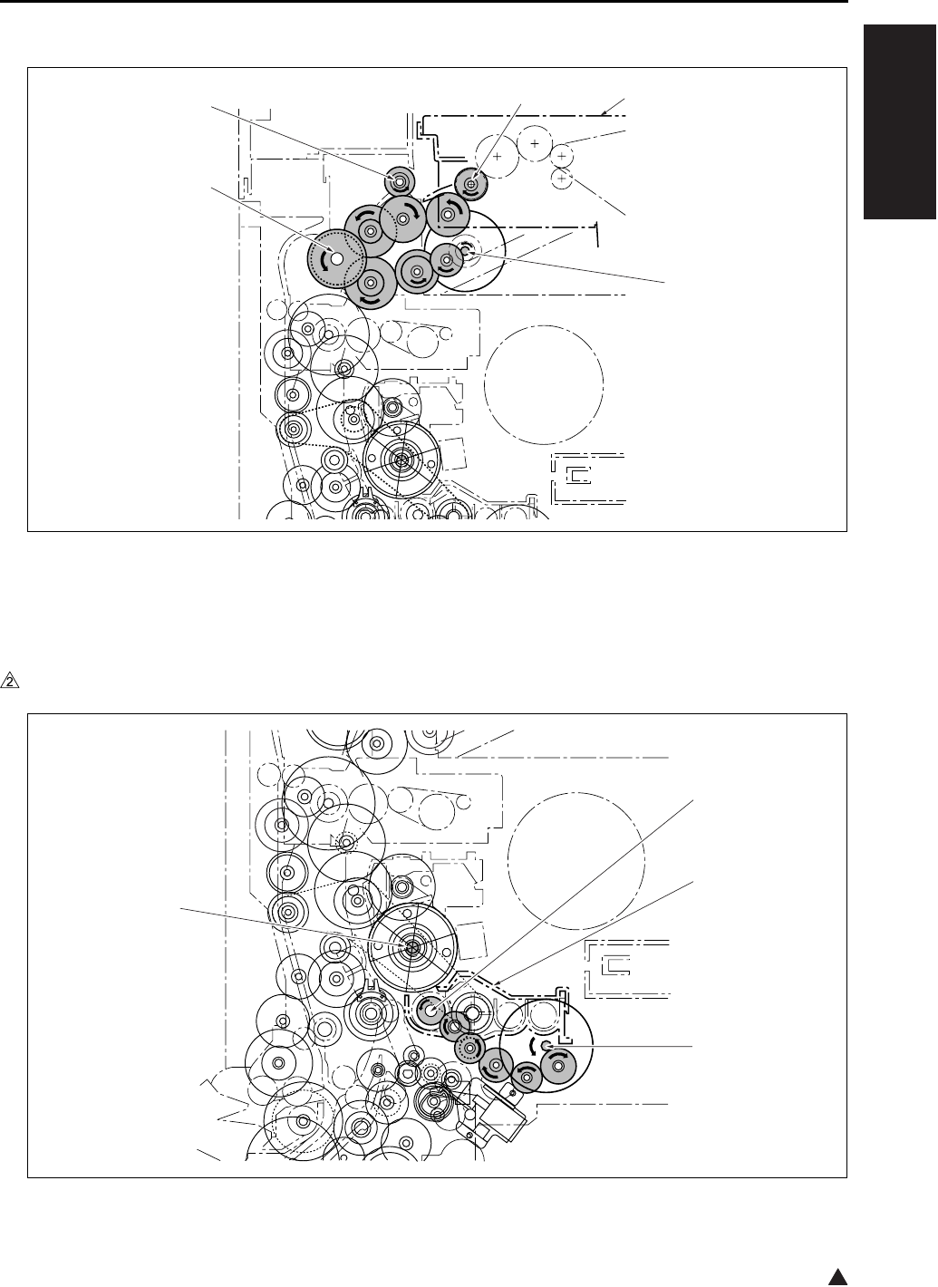
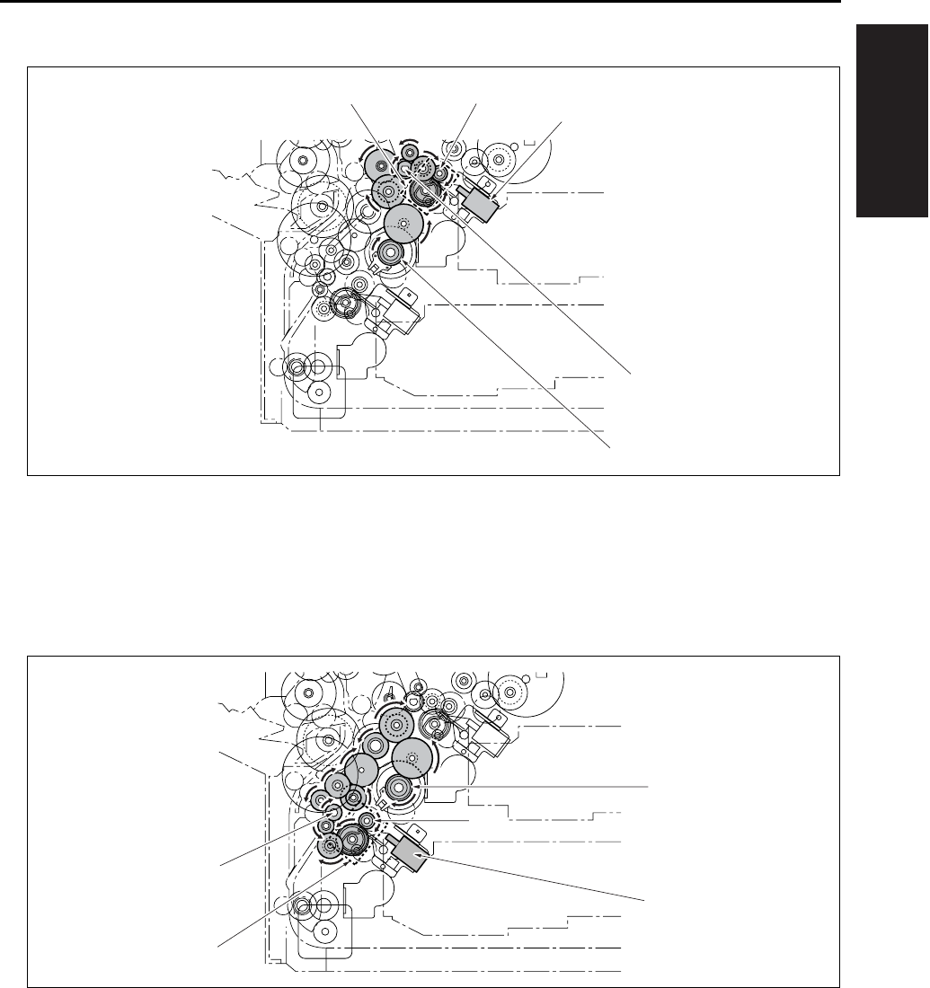
4.3 Fixing/Paper Exit Section/IT-101/RU-101 Drive
4.4 Developing Drive
In the case of the 7145
[1] IT-101 [4] Paper exit drive
[2] M11 (Fixing motor) [5] Drive coupling for IT-101 and RU-101
[3] Fixing unit drive
[1] Developing sleeve [3] M3 (Developing motor)
[2] Developing unit [4] Drum drive shaft
[1]
[2]
[3]
[4] [5]
[1]
[2]
[3]
[4]
DRIVE SYSTEM DIAGRAM
1-10
I OUTLINE
2
In the case of the 7235/7228/7222
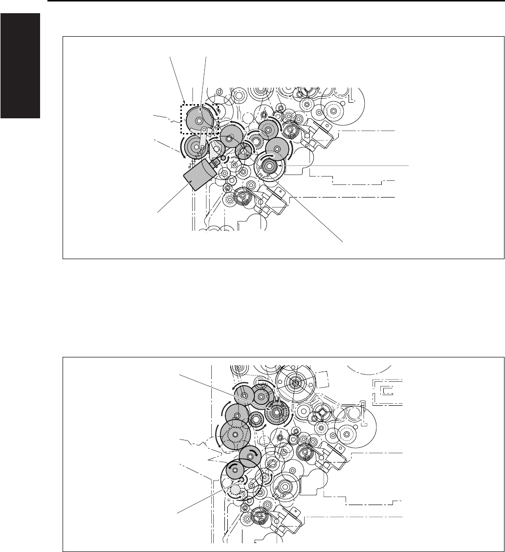
4.5 Paper Feed Drive
4.5.1 Drive from paper feed motor to loop clutch
[1] M1 (Main motor) [3] Developing unit
[2] Developing sleeve [4] Drum drive shaft
[1] MC2 (Loop clutch) [2] M9 (Paper feed motor)
7322ma1003
[2]
[1]
[3]
[4]
[1]
[2]
DRIVE SYSTEM DIAGRAM
1-11
I OUTLINE
4.5.2 Tray 1 drive
4.5.3 Tray 2 drive
[1]
[2]
SD1 (1st paper feed solenoid/U)
Conveyance roller
[4] Driven when SD1
(1st paper feed solenoid/U) is on.
[3] MC2 (Loop clutch) [5] Feed roller
[1]
[2]
MC2 (Loop clutch)
Feed roller
[4] Driven when SD2
(1st paper feed solenoid/L) is on.
[3] SD2 (1st paper feed solenoid/L) [5] Conveyance roller
[1]
[2]
[3]
[5][4]
[1]
[3]
[2]
[4]
[5]
DRIVE SYSTEM DIAGRAM
1-12
I OUTLINE
4.5.4 Bypass feed drive
4.5.5 Registration clutch drive
[1] MC2 (Loop clutch) [3] SD3 (Bypass solenoid)
[2] Conveyance roller [4] Driven when SD3 (Bypass solenoid) is on.
[5] Paper feed roller
[1] M9 (Paper feed motor) [2] MC1 (Registration clutch)
[1]
[2]
[3]
[4] [5]
[1]
[2]
DRIVE SYSTEM DIAGRAM
1-13
I OUTLINE
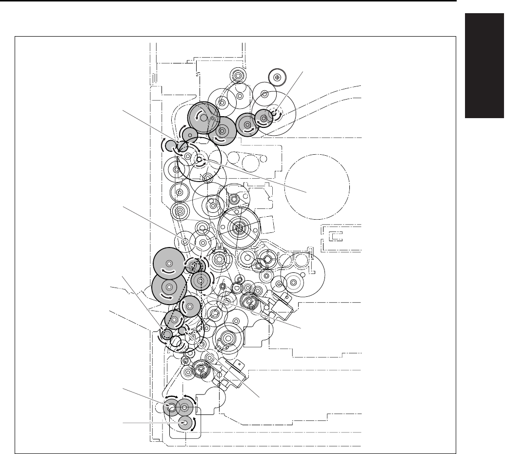
4.6 ADU Drive
[1] M1 (Main motor) [5] ADU roller
[2] Timing belt [6] ADU conveyance roller/2
[3] M9 (Paper feed motor) [7] Decurler roller
[4] M6 (ADU motor) [8] ADU conveyance roller/1
[9] M11 (Fixing motor)
[1]
[2]
[3]
[4]
[5]
[6]
[7]
[8]
[9]
DRIVE SYSTEM DIAGRAM
1-14
I OUTLINE
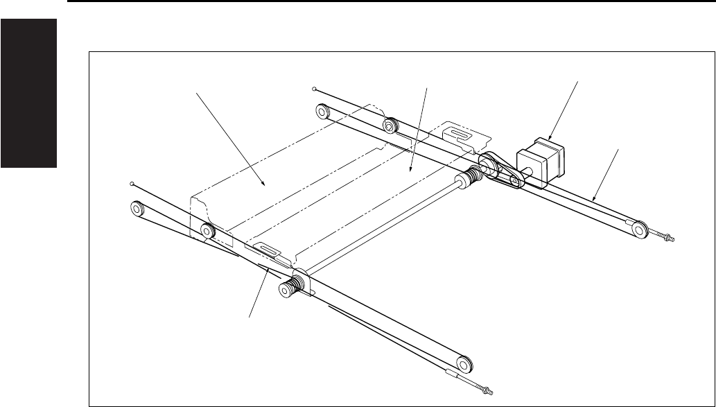
4.7 Scanner Drive
[1] Optical wire/R [4] Exposure unit
[2] Optical wire/F [5] M2 (Scanner motor)
[3] V-mirror unit
[1]
[2]
[3] [4] [5]
DRIVE SYSTEM DIAGRAM
1-15
I OUTLINE
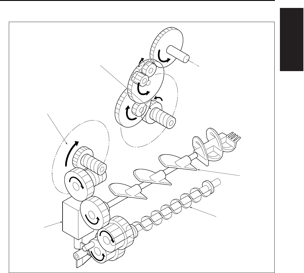
4.8 Toner Supply Drive
[1] Toner agitation plate [4] M4 (Toner supply motor 1)
[2] Toner conveyance screw [5] M10 (Toner supply motor 2)
[3] SD9 (Toner solenoid)
[1]
[2]
[4]
[3]
[5]

DRIVE SYSTEM DIAGRAM
1-16
I OUTLINE
Blank page
SCANNER SECTION
2-1
II UNIT EXPLANATION
2
II UNIT EXPLANATION
1. SCANNER SECTION
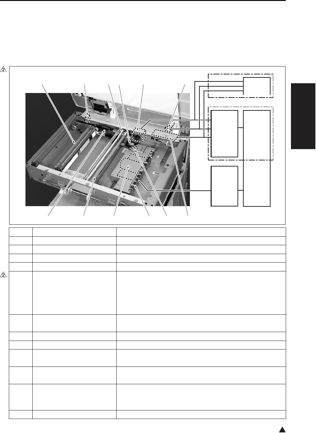
1.1 Composition
Symbol Name Function or method
[1] INV1 (Exposure lamp inverter) L1 (Exposure lamp) turn on
[2] PS17 (APS sensor) Detection of original size in the direction of sub-scanning
[3] ADB (A/D converter board) Digital conversion of analog signal
[4] CCD unit Photoelectric conversion of read image (600dpi)
[5] Exposure unit Image reading
Light source slit exposure
Scan speed
• Forward: 230mm/sec. (in 1:1 magnification)
• Backward: 383mm/sec.
[6] Optical wire Transmission of driving force from M2 to the exposure unit and
the V-mirror unit (front and rear)
[7] V-mirror unit Reflection of reading light (2nd and 3rd mirrors)
[8] PS14 (Scanner HP sensor) Exposure unit HP detection
[9] L1 (Exposure lamp) Light source for reading image,
Xenon lamp
[10] L1INVB (Power supply board
for exposure lamp)
Relay board for INV1 (Exposure lamp inverter) and L1 (Expo-
sure lamp)
[11] M2 (Scanner motor) Driving of the optical wire used to move the exposure unit and
the V-mirror unit
Three-phase step motor
[12] PS15 (APS timing sensor) RADF open/close detection
7322ma2001e
[2][3][4][5][6] [1]
[12][11][10][9][8][7]
CB
CB
SCDB
SCB
7235/7228/7222
7145

SCANNER SECTION
2-2
II UNIT EXPLANATION
2
1.2 Operation
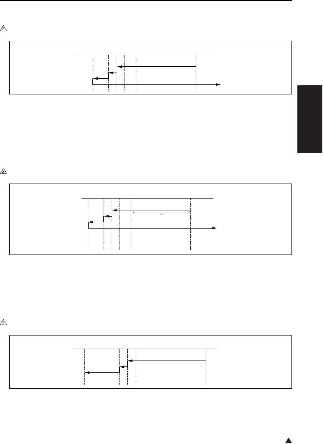
1.2.1 Initial operation when power is turned on and shading correction reading
When the SW2 (Sub power switch) comes on, the exposure unit starts a home position search. At this
time, the exposure unit uses the white reference plate attached on the back side of the original pressing
board for shading correction. However, two places on the white reference plate are read for correction.
The search procedure differs depending on whether the PS14 (Scanner HP sensor) is on or off while the
SW2 is on.
A. Home position search when the PS14 is turned on
B. Home position search when PS14 is turned off
1.2.2 Original reading mode
The following two modes are available for original reading; platen mode and DF mode. In platen mode, the
exposure unit moves as necessary to scan the original for reading. In DF mode, the RADF side moves the
original while the exposure unit stays fixed in a specified position (DF reading position).
[1] Exposure unit standby position [3] Shading correction position 1
[2] PS14 [4] Shading correction position 2
[1] Exposure unit standby position [3] Shading correction position 1
[2] PS14 [4] Shading correction position 2
7322ma2015
[1][2][3][4]
7322ma2016
[1][2][3][4]
SCANNER SECTION
2-3
II UNIT EXPLANATION
2
A. Exposure unit movement in platen mode
In platen mode, the scan sequence depends on the copy density selection (either AE or manual).
(1) In manual density copy:
Note:
• When the tray 1 is selected manually, but not in APS, the shading operation is not executed.
(2) In AE copy:
B. Exposure unit movement in DF mode
[1]
[2]
Exposure unit standby position
PS14
[5] Position at which the approach run of the
exposure unit is started
[3]
[4]
Shading correction position 1
Shading correction position 2
[6] Position at which the reading of an image
is started
[1]
[2]
[3]
[4]
Exposure unit standby position
AE scanning range
PS14
Shading correction position 1
[5] Shading correction position 2
[6] Position at which the approach run of the
exposure unit is started
[7] Position at which the reading of an image
is started
[1] Exposure unit standby position [4] Shading correction position 2
[2] PS14 [5] DF reading position
[3] Shading correction position 1
7322ma2017
[1][6][2][3][4][5]
[1][7]
[2]
[3][4][5][6]
7322ma2018
7322ma2019
[1][2][3][4][5]
SCANNER SECTION
2-4
II UNIT EXPLANATION
1.2.3 Original read control
The light from the exposure lamp reflects back from the original, passes through a lens, and hits the CCD
sensor. The CCD sensor generates an electric signal (analog signal) corresponding to the light intensity.
Then, according to the instruction from the SCB (System control board), the ADB (A/D conversion board)
converts this signal into a digital signal.
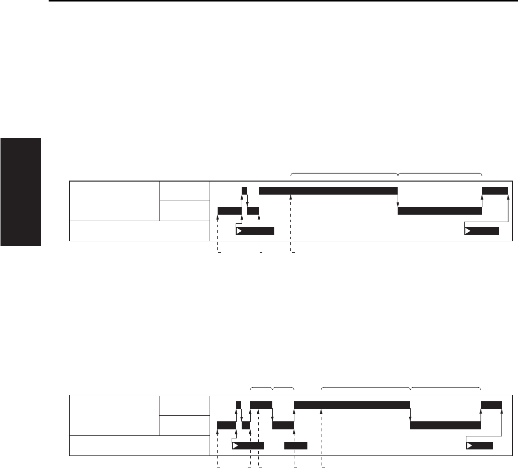
A. Original read timing
(1) Platen mode, when the manual density is being set
(2) Platen mode, when the AE density is being set
[1] START button (ON) [4]
Position at which reading of the original starts
[2] Exposure lamp (forward) [5] Exposure scanning (backward)
[3] Position to which the exposure unit starts
[1]
[2]
[3]
[4]
START button (ON)
AE scanning (forward)
Position to which the exposure unit starts
Position at which reading of the AE density
started
[5]
[6]
[7]
[8]
AE scanning (backward)
Exposure lamp (forward)
Position at which reading of the original
starts
Exposure scanning (backward)
[1] [3] [4]
[2] [5]
M2 (Scanner motor)
PS14 (Scanner HP sensor)
F
R
[6] [8][2] [5]
[4] [7][1] [3][3]
M2 (Scanner motor)
F
R
PS14 (Scanner HP sensor)
SCANNER SECTION
2-5
II UNIT EXPLANATION
2
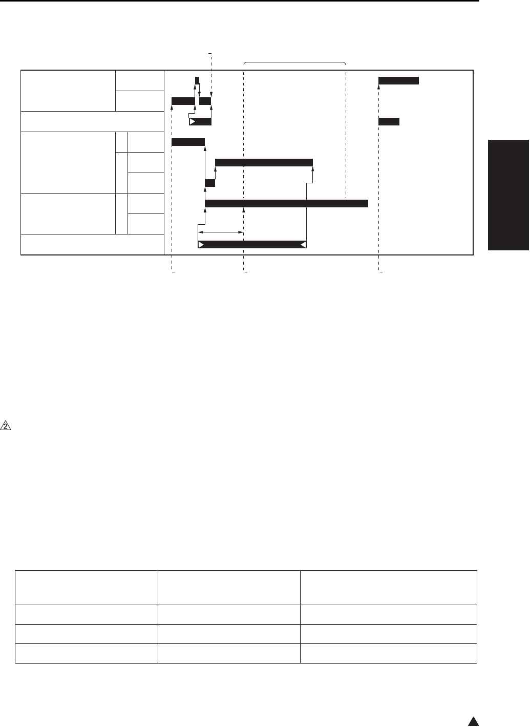
B. Original read timing (DF mode) *1
*1 In the DF mode, the operation when the manual density setting and the AE density setting is the same.
1.2.4 APS control
The APS control is carried out at close detection of the RADF, and controlled by the CB (Main body control
board), based on signals from the PS17 (APS sensor) and the CCD sensor. (For APS control by the
RADF, see DF service manual.)
A. APS operation
The PS17 (APS sensor) detects the original size in the sub scanning direction, while the CCD sensor
detects the original size in the main scanning direction.
B. Relationship between each of the sensors and the original size
[1] START button (ON) [4] Exposure conveyance
[2] DF reading position [5]
Position at which reading of the original starts.
[3] Position to which the original has been
conveyed in the specified distance.
[6] Starting point from the DF reading position
to the home position (exposure unit).
Original size CCD sensor
(Length of detection: mm)
PS17
(ON/OFF)
A3 297 ON
11 x 17 279.4 ON
B4 257 ON
[1]
[3]
[4][2]
[5] [6]
M2 (Scanner motor)
F
R
PS14 (Scanner HP sensor)
M301
(Original feed motor)
R
F
M302
(Original conveyance motor)
F
PS308 (Original registration sensor)
250mm/s
230mm/s
460mm/s
230mm/s
460mm/s
SCANNER SECTION
2-6
II UNIT EXPLANATION
*1 8.5 x 14 cannot be distinguished from 8.5 x 11R, and is detected as 8.5 x 11R.
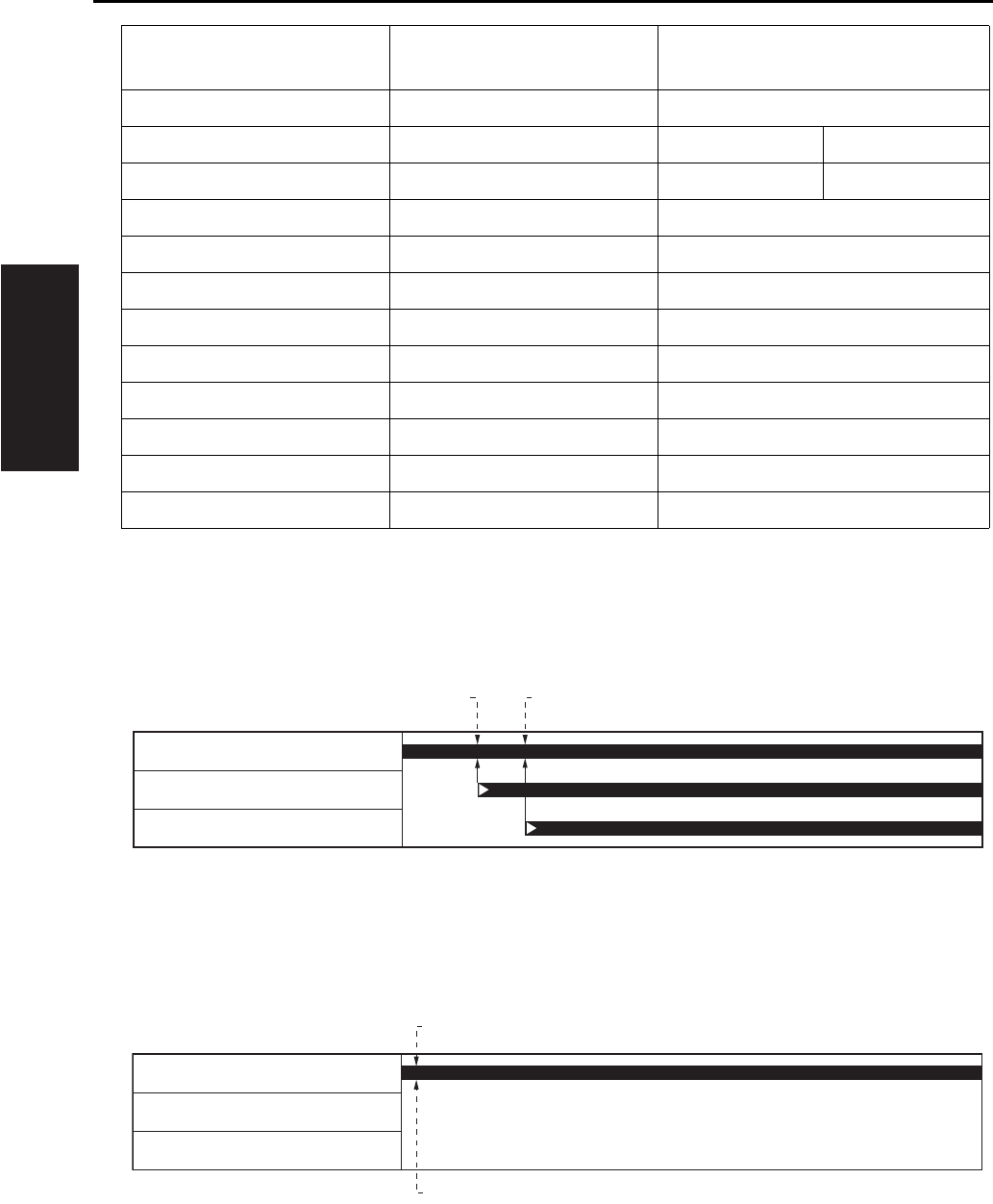
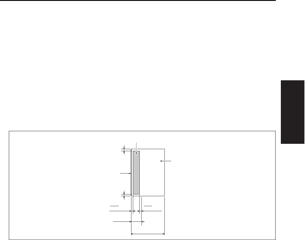
C. APS detection timing
(1) Platen mode (when the RADF is closed)
(2) Platen mode (when the RADF is open)
8.5 x 14 *1 215.9 ON
8.5 x 11R 215.9 Metric system: ON Inch system: OFF
A4R 210 Metric system: ON Inch system: OFF
A4 297 OFF
8.5 x 11 279.4 OFF
B5R 257 OFF
A5R 210 OFF
B5 182 OFF
A5 148 OFF
5.5 x 8.5 139.7 OFF
B6 128 OFF
Postcard 102 OFF
[1] 1st original size detection [2] 2nd original size detection
[1] Original size detection [2] START button (ON)
Original size CCD sensor
(Length of detection: mm)
PS17
(ON/OFF)
[1] [2]
PS17 (APS sensor)
PS15 (APS timing sensor)
PS303 (DF open/close sensor)
[2]
[1]
PS17 (APS sensor)
PS15 (APS timing sensor)
PS303 (DF open/close sensor)
SCANNER SECTION
2-7
II UNIT EXPLANATION
1.2.5 AE control
During AE scan, the CCD sensor provided on the ADB (A/D conversion board) reads the density level of
the original. The CPU on the SCB (System control board) process the data and, based on the results,
selects the γ correction curve that will best reproduce the original.
A. AE sampling range
(1) While in platen copying
Main scanning direction
• Based on the original size recognized in the APS or out-of-original erasure mode, the range excepting
10mm in front and in rear.
Sub-scanning direction
• The range of 30mm from the leading edge of the original. However, the range excepting L/100mm in
left and right when the length of the original is L mm.
[1] Original [3] AE sampling range
[2] Leading edge of original
10 mm
10 mm
30 mm
L mm
mm
L
100 mm
L
100
[1]
[2]
[3]
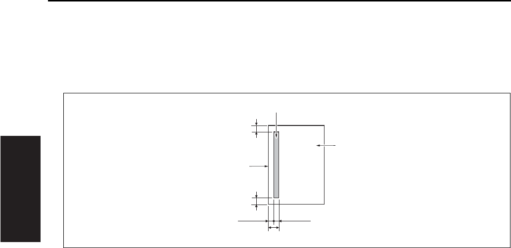
SCANNER SECTION
2-8
II UNIT EXPLANATION
(2) While in DF copying
Main scanning direction
• Based on the original size recognized in the APS, the range excepting 20mm in front and in rear.
Sub-scanning direction
• The range between 1.5mm and 2.9mm from the leading edge of the original.
1.2.6 Image processing
A. AOC (Automatic offset control)
The analog offset voltage for the CCD sensor output is automatically adjusted by IC on the ADB (A/D
conversion board) so that this level becomes the lower limit for the A/D converter.
B. AGC (Automatic gain control)
The analog amplification for the CCD sensor output is automatically adjusted so that the CCD sensor
output level in the shading white correction becomes the upper limit for the A/D converter.
C. Shading correction
(1) Types of the shading correction
• White correction
• Black correction
(2) Execution timing
• At SW2 (Sub power switch) ON
• At the start of scan job
D. Other image processing
(1) Brightness/density conversion
(2) Text/dot pattern judgement
(3) Filtering
(4) Magnification change processing
(5) Error diffusion processing
(6) Data compression/elongation processing
[1] Original [3] AE sampling range
[2] Leading edge of original
20 mm
20 mm
1.4 mm
2.9 mm
1.5 mm
[1]
[2]
[3]
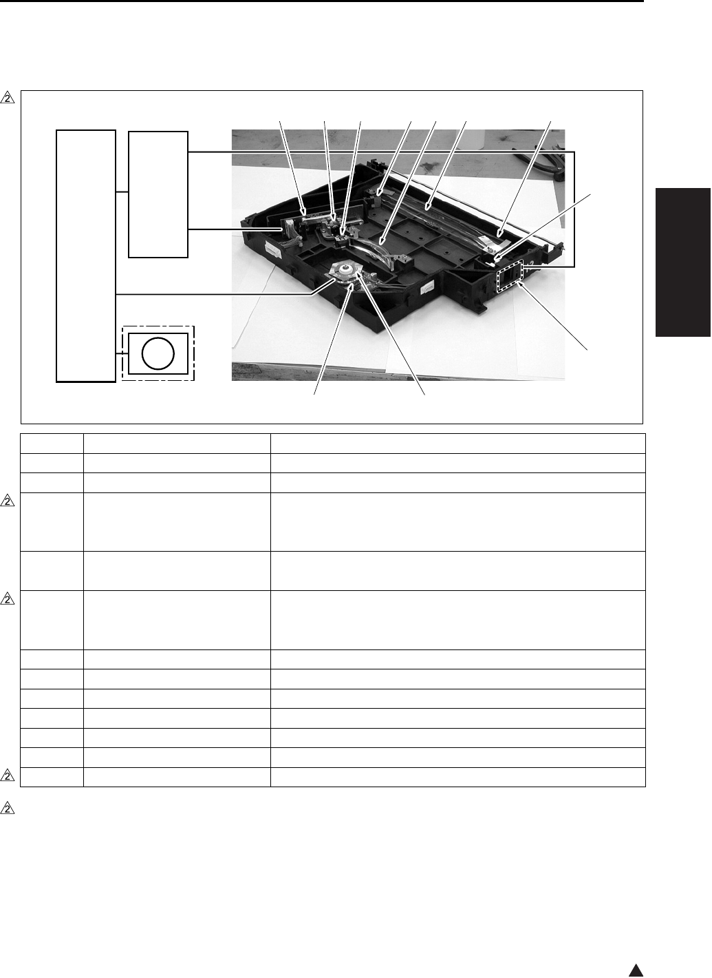
WRITE UNIT
2-9
II UNIT EXPLANATION
2
2. WRITE UNIT
2.1 Composition
*1 7235 only
Symbol Name Function or method
[1] Index lens Converging of laser beams reflected from the index mirror
[2] INDEX (Index sensor board)
Control of the laser write position in the main scanning direction
[3] Polygon mirror Laser beam scanning
Hexahedron, 27,165rpm (7145) /38,976rpm (7235) /
33,071rpm (7228/7222)
[4] M5 (Polygon motor) Polygon mirror drive
DC brushless motor, PLL control
[5] LDB (LD drive board) Laser emission drive
1-chip/2-beam system, 15mW 780mm (7145)
1-chip/1-beam system, 5mW 780mm (Except the 7145)
[6] Collimator lens Making diffused laser beam parallel
[7] Cylindrical lens 1
Correction of the laser path against error in the angle of the polygon mirror
[8] Index mirror Reflection of laser beam upon the INDEX (Index senror board)
[9] fθ lens
Unified laser scanning speed against the laser irradiation surface on the drum
[10] Cylindrical lens 2
Correction of the laser path against error in the angle of the polygon mirror
[11] Dust-proof glass
Preventive measure for keeping the interior of the write unit clean
FM7*1 Polygon cooling fan
Cooling of the M5 (
Polygon motor
)
7322ma2002
FM7
[3][4]
[11][10][9][8][7][6][5]
[1]
[2]
CB
SCB
7235 only

WRITE UNIT
2-10
II UNIT EXPLANATION
2
2.2 Operation
2.2.1 Image writing
The image data from the CCD sensor is converted into digital form by the ADB (A/D conversion board),
and its image processing is then carried out on the SCB (System control board). Based on the processed
image data, the image is written onto the drum by the laser beam output from the LDB (LD drive board).
2.2.2 Write control
A. Dot diameter adjustment
The sensor on the toner control sensor board detects the patch image density on the drum, and the
LDB (LD drive board) controls the quantity of laser beam so that its output value becomes the speci-
fied value.
(1) Timing for execution
a. While in copying
• Executed once for every 20 copies added up. However, when 20 copies are added up in the middle of
the job, the execution is made at the time of completion of the job.
b. Anytime other than while in copying
• While in the L inspection
• When the drum counter is reset
• When the sub power is turned on. However, this is subject to the settings 6 and 7 of the DIPSW16 in
the 25 mode.
B. APC (Automatic power control)
The LDB (LD drive board) monitors the laser output value for every one scan, and maintains the laser
beam quantity at the fixed level by driving the laser so that it becomes the output value set for the dot
diameter adjustment.
C. Write timing
The SCB (System control board) uses a laser detection signal from the INDEX (Index sensor board) to
determine the starting point for laser writing for every one scan in the drum shaft direction.
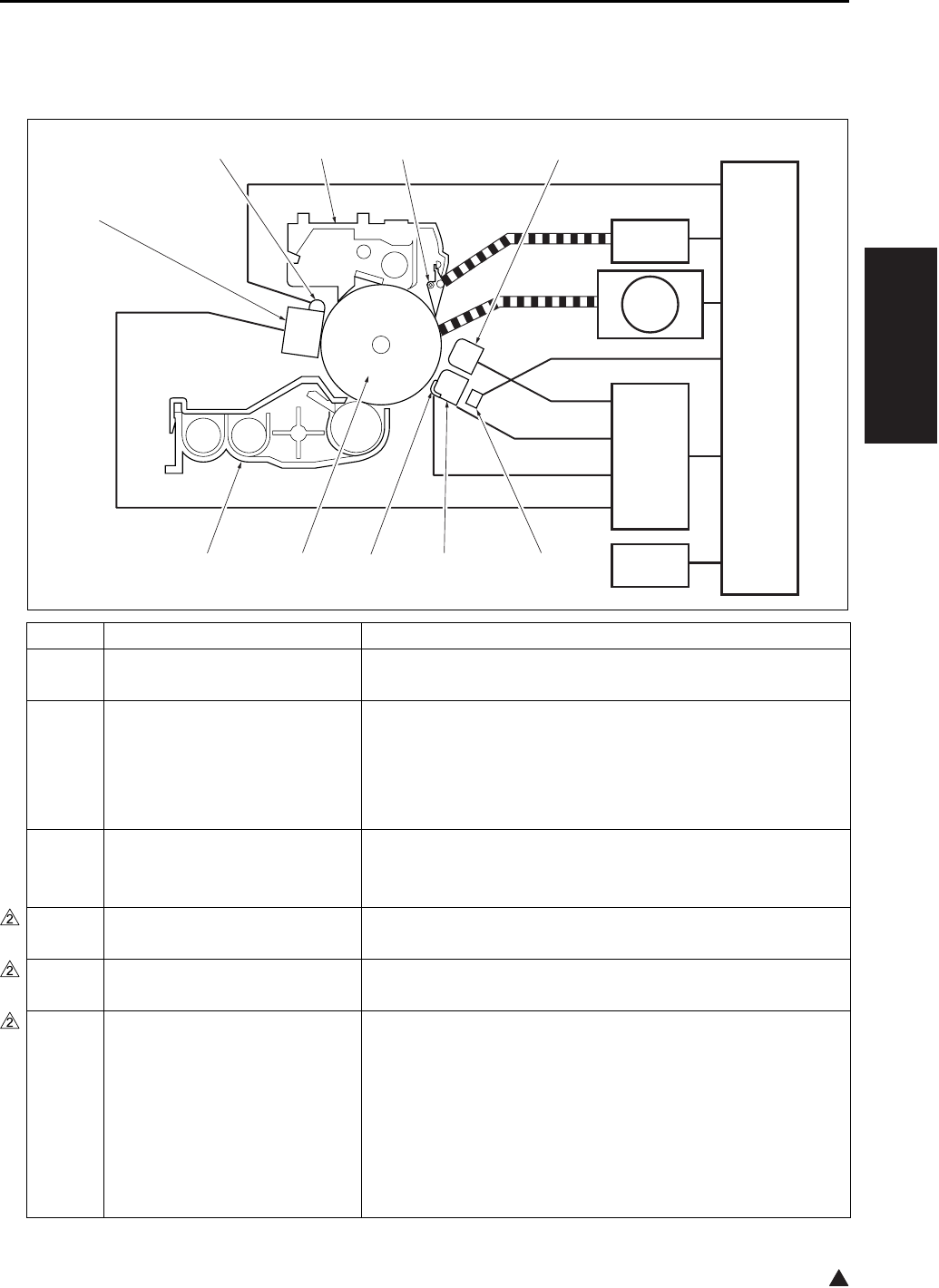
DRUM UNIT
2-11
II UNIT EXPLANATION
2
3. DRUM UNIT
3.1 Composition
Symbol Name Function or method
[1] TSL
(Transfer synchronization lamp)
Separation support
LED
[2] Transfer corona unit Transfer of toner from the drum to paper
DC positive corona discharge *1
Wire discharge: Tungsten wire with oxide film (φ 0.06mm)
With manual wire cleaning mechanism provided
Constant current DC output range: 0 to 350 µA
[3] Paper entrance guide plate Conveyance guide for paper supplied
High voltage applied to prevent toner adhesion: -500VDC
(constant voltage)
[4] Drum Image formation base
OPC drum (φ 60mm)
[5] Developing unit Formation of a toner image on the drum
(See “4. Developing unit”.)
[6] Charging corona unit Application of electric charge on the drum surface
DC corona discharge (Scotron)
Wire discharge: Gold-plated skin-pass tungsten wire
(φ 0.06mm)
With manual wire cleaning mechanism provided
Constant current DC output range: -320 to -1000 µA
Grid bias: Charging control plate
Constant current DC output range: -450 to -1090V
[1]
[10][9][8][7]
[6]
[2][3][4][5]
CB
HV
SD7
M1
TCSB

DRUM UNIT
2-12
II UNIT EXPLANATION
2
*1 Control is made so that an output value becomes a little higher for a thick paper and a little lower for a
thin paper as compared with a plain paper.
Note for the transfer/separation corona
Caution:
• A copy should not be made when the ADU door is open with the interlock forcibly turned on. Oth-
erwise, the contact (spring) of the ADU door develops high voltage and you may get an electric
shock.
[7] PCL
(Pre-charging exposure lamp)
Erasure of potential on the drum surface
LED
[8] Cleaning/recycle section Cleaning and collection of toner on the drum
(See “5. Toner supply/cleaning/recycle section”.)
[9] Separation claw Support for the separation of paper from the drum
Pressure/release method by SD7 (Separation claw solenoid)
[10] Separation corona unit Separation of transferred paper from the drum
AC/DC corona discharge *1
Wire discharge: Tungsten wire with oxide film (φ 0.06mm)
With manual wire cleaning mechanism provided
Constant current AC output range: 1.5 to 5.0kV
Constant current DC output range: 0 to -300µA
SD7 Separation claw solenoid Separation claw pressure/release
24VDC drive
M1 Main motor Driving of the drum, cleaning/recycling section
DC brushless motor, PLL control
HV High voltage power High voltage power supply to the charging corona, transfer
corona, separation corona, paper entrance guide plate and
developing bias
Method to increase voltage by inverter from 24VDC
TCSB Toner control sensor board Detection of the patch image density on the drum
Detection of temperature around the drum
Symbol Name Function or method
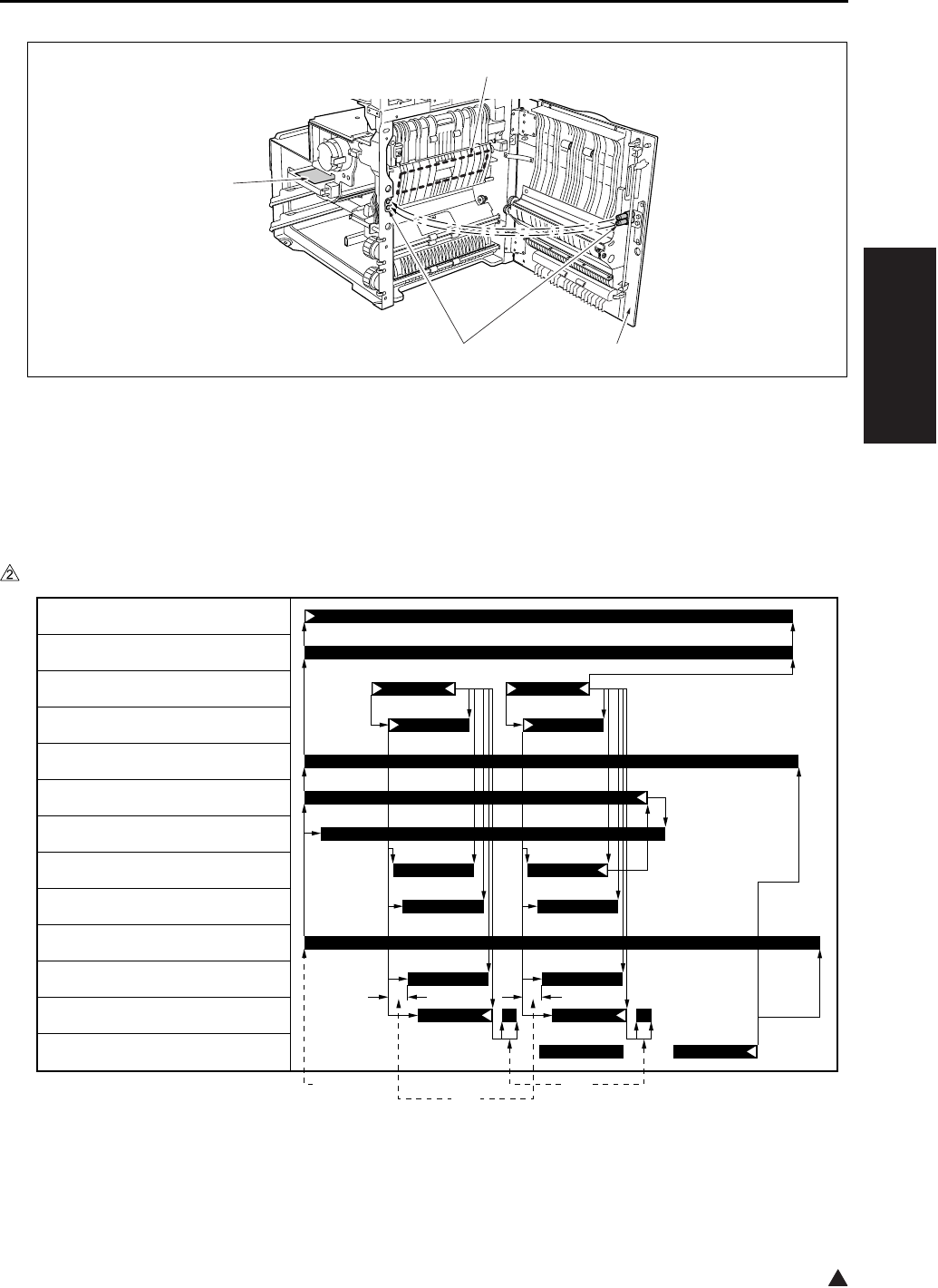
DRUM UNIT
2-13
II UNIT EXPLANATION
2
3.2 Operation
3.2.1 Image formation timing (when copying two sheets)
A. In the case of the 7145
[1] ADU door [3] Transfer/separation corona unit
[2] Contact [4] HV (High voltage unit)
[1] START button (ON) [3] Driving of the separation claw to prevent
the trailing edge of paper from getting
stained.
[2] Varies depending on the type of paper.
[3]
[4]
[2] [1]
7322ma2020
[2] [3][1]
M1 (Main motor)
M3 (Developing motor)
PS1 (Registration sensor)
MC1 (Registration clutch)
PCL (Pre-charging exposure lamp)
HV (Charging corona)
HV (Developing bias)
HV (Transfer corona)
HV (Separation corona)
HV (Paper entrance guide plate)
TSL (Transfer synchronization lamp)
DS7 (Separation claw solenoid)
PS2 (Fixing exit sensor)
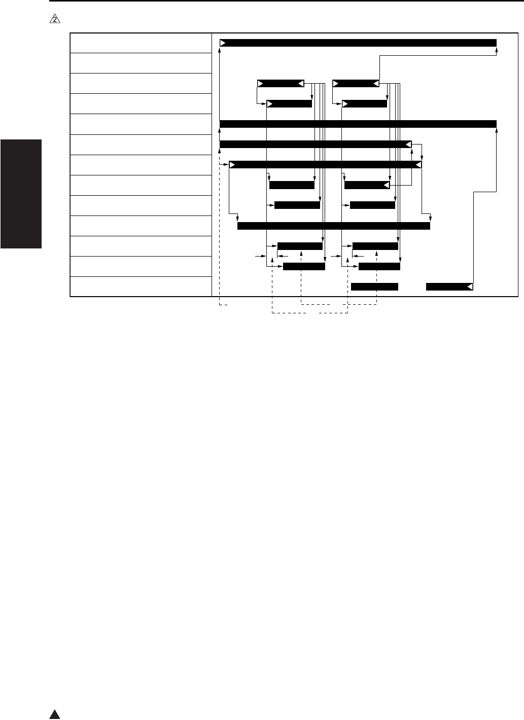
DRUM UNIT
2-14
II UNIT EXPLANATION
2
B. In the case of the 7235/7228/7222
[1] START button (ON) [3] Varies depending on the environment in
which it is installed.[2] Varies depending on the type of paper.
7322ma2012
[2]
[3]
[1]
M1 (Main motor)
PS1 (Registration sensor)
MC1 (Registration clutch)
PCL (Pre-charging exposure lamp)
HV (Charging corona)
HV (Developing bias)
HV (Transfer corona)
HV (Separation corona)
HV (Paper entrance guide plate)
TSL (Transfer synchronization lamp)
DS7 (Separation claw solenoid)
PS2 (Fixing exit sensor)
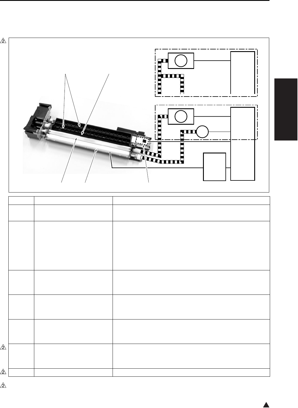
DEVELOPING UNIT
2-15
II UNIT EXPLANATION
2
4. DEVELOPING UNIT
4.1 Composition
*1 7145 only
Symbol Name Function or method
[1] TDS (Toner density sensor) Detection of toner density in the developing unit
L detection method
[2] Developing sleeve Coveyance of developing materials by magnetic force to the
drum surface
Two-component developing method (developing materials:
Toner + Carrier)
Developing bias voltage applied
Constant voltage DC output range: -350 to -830V
[3] Developing regulation plate Regulation of the spiking amount of developing materials on
the developing sleeve
Regulation plate method
[4] Agitator screw Agitation of developer and conveyance of developing materials
to the agitator wheel
Agitator wheel method
[5] Agitator wheel Agitation of developer and conveyance of developing materials
to the developing sleeve
4-vane wheel method
M1 Main motor Driving of the agitating turbine, the agitating screw and the
developing sleeve (except the 7145)
DC brushless motor, PLL control
M3*1 Developing motor Driving of the developing sleeve
7322ma2003e
CB
HV
M3
M1
CB
M1
[1]
[5][4]
[2][3]
7235/7228/7222
7145

DEVELOPING UNIT
2-16
II UNIT EXPLANATION
4.2 Operation
4.2.1 Developing control
For details of each operation timing of developing, see “3. Drum section”.
4.2.2 Control of toner density in the developing unit
The TDS (Toner density sensor) uses the L detection method (detection of permeability in developing
materials) to detect the toner density of developing materials. The value thus obtained is compared with
the standard value of the toner density for the L detection adjustment that is recorded in the PCU con-
tained in the CB (Main body control board) to see if toner should be supplied or not. (For details of toner
supply, see “5. Toner supply/cleaning/recycling section”.)
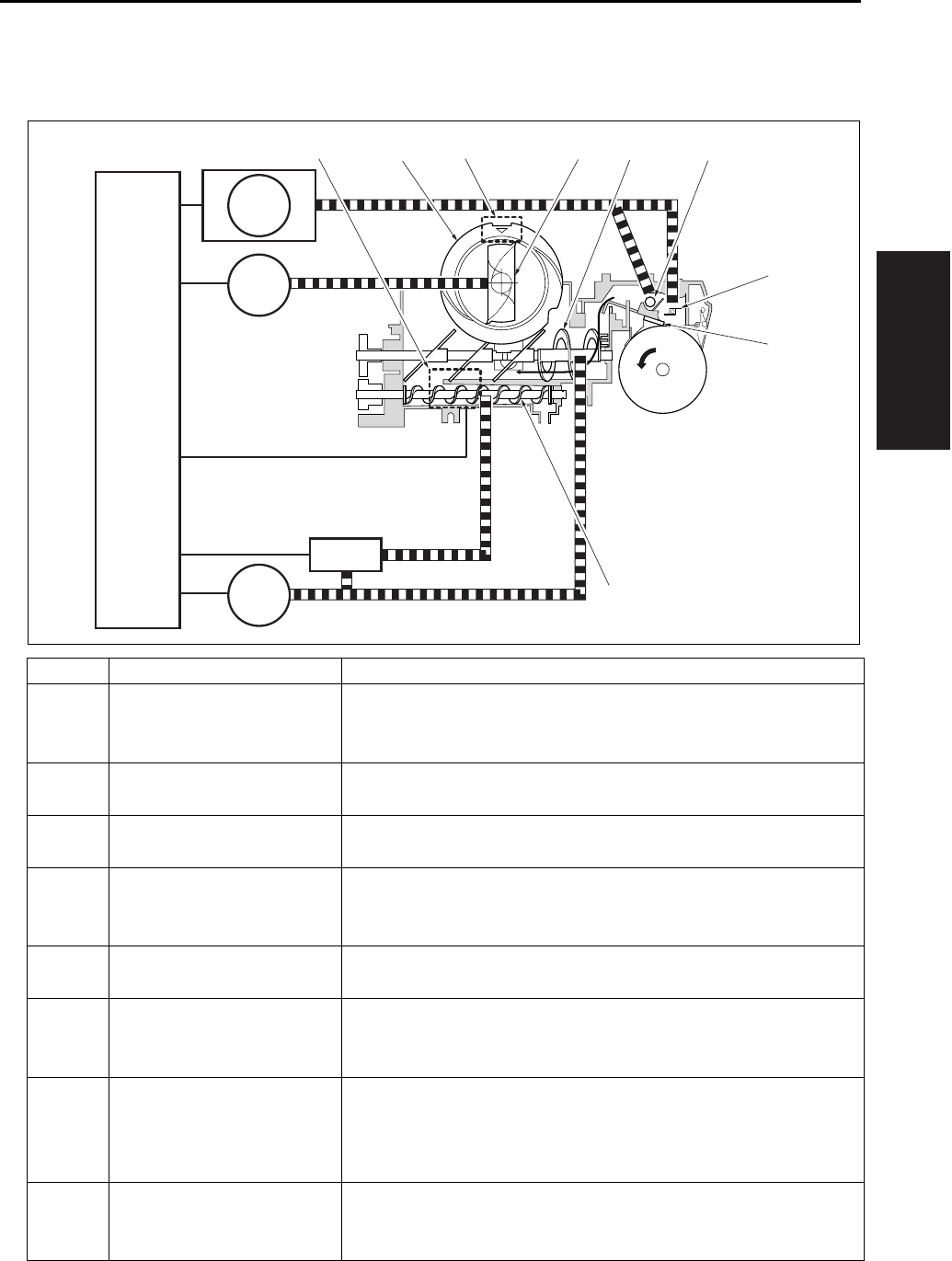
TONER SUPPLY/CLEANING/RECYCLE UNIT
2-17
II UNIT EXPLANATION
5. TONER SUPPLY/CLEANING/RECYCLE UNIT
5.1 Composition
Symbol Name Function or method
[1] Toner collection sheet Collection of toner separated by the cleaning blade from the drum
surface
Rotating collection method
[2] Cleaning blade Drun cleaning
Drum contact/separation method
[3] Toner conveyance screw Agitation of toner and conveyance of toner to the developing unit
Screw method
[4] TLD (Toner level sensor) Detection of the toner level in the toner supply unit (Detected
when the residual quantity of toner gets to about 30g.)
Piezo element method
[5] Toner bottle Toner supply (bottle capacity: 676g)
Toner bottle rotation method
[6] Toner supply paddle Conveyance of toner from the toner bottle to the toner supply unit
Fixed method (Since the toner bottle rotates, this serves as the
toner introduction section.)
[7] Toner agitation plate Agitation of toner supplied from the toner bottle and the cleaning/
recycle section, and conveyance of the toner to the toner convey-
ance screw
Screw method
[8] Collected toner conveyance
screw
Conveyance of toner from the cleaning section to the toner supply
unit
Screw method
[3]
[2]
[1]
[7][6] [8][5] [9][4]
CB
M1
M4
SD9
M10

TONER SUPPLY/CLEANING/RECYCLE UNIT
2-18
II UNIT EXPLANATION
5.2 Operation
5.2.1 Toner supply control when the toner level in the toner supply section gets reduced
A. Toner supply operation:
When toner in the toner supply unit is running short, the TLD (Toner level sensor) turns on. This
causes the M10 (Toner supply motor 2) to turn on to rotate the toner bottle and replenish toner to the
toner supply unit. When toner has been supplied, the TLD turns off to monitor the toner level.
B. Operation when toner is not supplied:
When the TLD (Toner level sensor) has been kept turned on for the specified period of time, it is con-
sidered that no toner remains in the toner bottle and a message is displayed on the operation LCD.
C. Toner level detection timing:
The TLD (Toner level sensor) detects at all times the toner level during copy operation.
[9] PS5 (Toner bottle sensor) Detection of the setting of the toner bottle
Photosensor
M1 Main motor Driving of the toner collection sheet and the collected toner con-
veyance screw
DC brushless motor, PLL control
M4 Toner supply motor 1 Driving of the toner conveyance screw and the toner agitator plate
Stepping motor
M10 Toner supply motor 2 Toner bottle
Stepping motor
SD9 Toner solenoid Transmission of driving force from the M4 (Toner supply motor) to
the toner conveyance screw
24VDC drive
Symbol Name Function or method

TONER SUPPLY/CLEANING/RECYCLE UNIT
2-19
II UNIT EXPLANATION
5.2.2 Toner supply control when toner density in the developing unit gets reduced
A. When power is on:
The TDS (Toner density sensor) detects the toner density in the developing unit the specified period of
time after the SW2 (Sub power switch) is turned on. When the value thus detected at this time is
below the initial density recorded in the CPU contained in the CB (Main body control board), the M4
(Toner supply motor 1) and the SD9 (Toner solenoid) are turned on to start to replenish toner up to the
specified level of density.
B. While in copy operation:
While in copy operation, the TDS (Toner density sensor) monitors the toner density. Using the output
voltage of the TDS to turn on the SD9 (Toner solenoid), the M4 (Toner supply motor 1) determines the
time required for toner supply.
TDS output voltage Time required for toner supply
2.01V or less 0 sec.
2.02 to 2.08V 0.10 sec.
2.09 to 2.16V 0.20 sec.
2.17 to 2.23V 0.30 sec.
2.24 to 2.31V 0.40 sec.
2.32 to 2.39V 0.50 sec.
2.40V or more 0.70 sec.
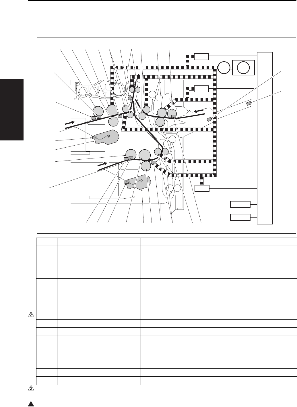
PAPER FEED UNIT
2-20
II UNIT EXPLANATION
2
6. PAPER FEED UNIT
6.1 Composition
Symbol Name Function or method
[1] VRI (Bypass tray paper size
sensor VR)
Detection of paper size in the direction of the width of the by-
pass tray
[2] PS20
(Bypass tray paper size sensor)
Detection of paper size in the direction of the length of the by-
pass tray
[3] PS13
(Bypass tray no paper sensor)
Detection of the presence of bypass feed paper
[4] Double feed prevention roller Double feed prevention of paper, Torque limiter
[5] Conveyance roller Paper conveyance
[6]*1 PS22 (Timing sensor/L) Detection of tray 2 paper conveyance condition
[7] Double feed prevention roller Double feed prevention of paper, Torque limiter
[8] M8 (Tray motor/L) Tray 2 paper liftup plate drive, DC motor
[9] Feed roller 1st paper feed power transmission
[10] PS12 (Tray set sensor/L) Tray 2 detection and remaining paper detection
[11] PS10 (Upper limit sensor/L) Tray 2 paper upper limit detection
[12] PS11 (No paper sensor/L) Detection of the presence of tray 2 paper
[13] Paper feed roller Tray 2 paper feed
[14] M7 (Tray motor/U) Tray 1 paper liftup plate drive, DC motor
*1 7145/7235/7228 only
SD2
SD3
CB
SD1
MC2
PFDB/U
PFDB/L
[18] [19] [20] [21] [22] [23] [24] [25] [26] [27]
[1]
[2]
[3][4][5][6][7][8][9][10][11][12]
[13]
[14]
[15]
[16]
[17]
M9

PAPER FEED UNIT
2-21
II UNIT EXPLANATION
2
6.2 Operation
6.2.1 Tray up drive control
Since the operation is the same for both the tray 1 and the tray 2, the explanation is given of the tray 1.
When the paper feed tray is set, the PS9 (Tray set sensor/U) detects the tray with the M7 (Tray motor/U)
turned on. This causes the paper up/down plate in the tray to go up. When the PS7 (Upper limit sensor/U)
detects the paper upper limit, the M7 is turned off. When the sheets of paper get reduced as they are being
fed through, the PS7 detects no remaining paper. At this time, the M7 is kept turned on until it detects the
paper upper limit again, and paper is raised up to the specified level at all times.
When the tray is removed, its coupling with the drive section is disconnected to let the paper up/down plate
go down by its own weight.
When papar is supplied by the bypass feed method and the SD3 (Bypass solenoid) turns on after the M9
(Paper feed motor) turns on, the bypass plate goes up to raise paper.
[15] PS9 (Tray set sensor/U) Tray 1 detection and remaining paper detection
[16] PS8 (No paper sensor/U) Detection of the presence of tray 1 paper
[17] PS7 (Upper limit sensor/U) Tray 1 paper upper limit detection
[18] Paper feed roller Tray 1 paper feed
[19] Double feed prevention roller Double feed prevention of paper, Torque limiter
[20] Feed roller 1st paper feed power transmission
[21]*1 PS21 (Timing sensor/U) Detection of tray 1 paper conveyance condition
[22] Conveyance roller Paper conveyance
[23] PS1 (Registration sensor) Detection of the paper passage for the Registration roller rota-
tion ON/OFF
[24] Registration roller Paper conveyance
[25] Conveyance roller Paper conveyance
[26] Feed roller Bypass tray paper feed
[27] Paper feed roller Paper feed
M9 Paper feed motor Paper feed system drive, DC brushless PLL control
MC2 Loop clutch 1st paper feed power transmission
SD1 1st paper feed solenoid/U Tray 1 paper feed power transmission
SD2 1st paper feed solenoid/L Tray 2 paper feed power transmission
SD3 Bypass solenoid Bypass tray paper feed power transmission
PFDB/U
Paper feed detection board/U Tray 1 paper size detection
PFDB/L
Paper feed detection board/L Tray 2 paper size detection
CB Main body control board Overall control
*1 7145/7235/7228 only
Symbol Name Function or method
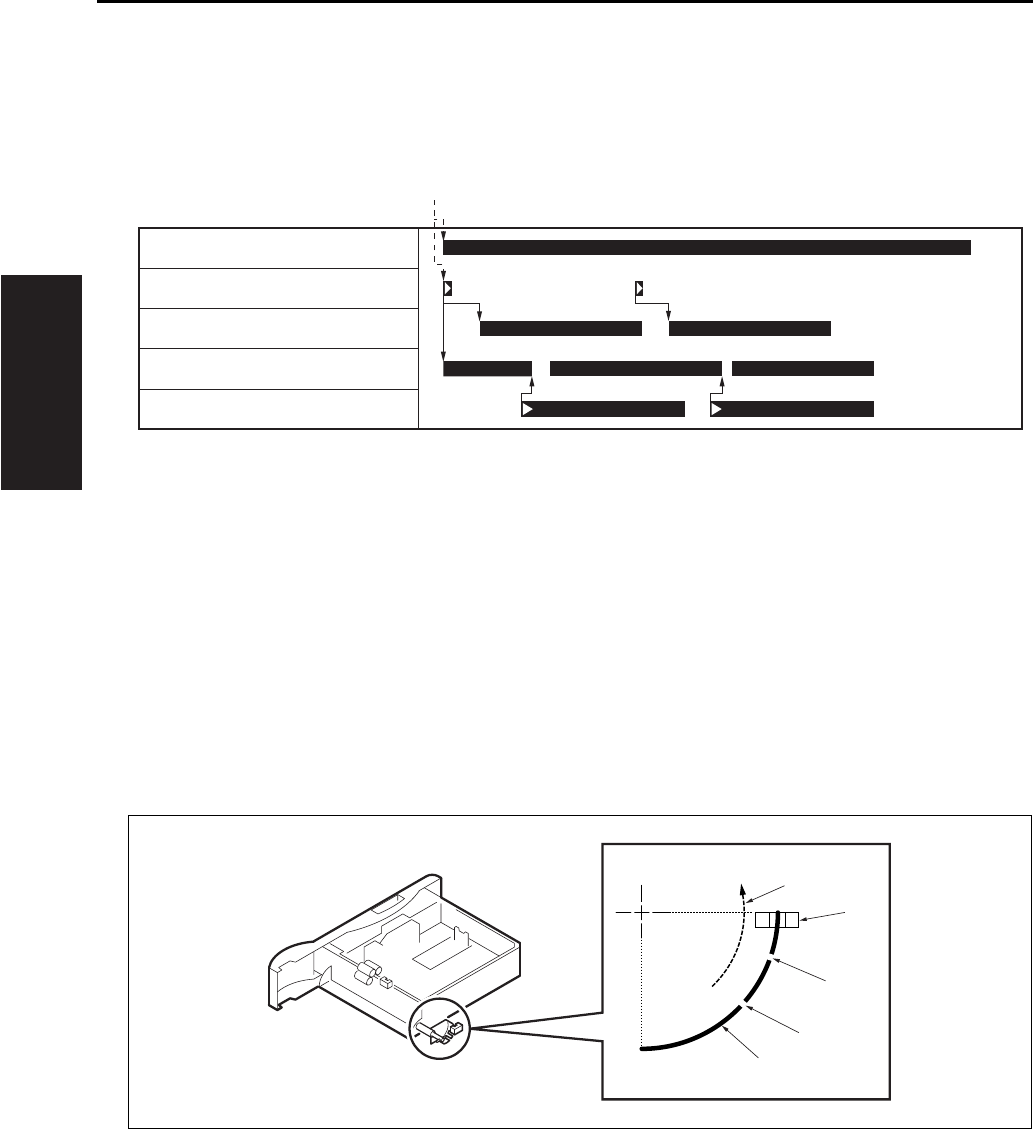
PAPER FEED UNIT
2-22
II UNIT EXPLANATION
6.2.2 Paper feed control
The following shows the timing of paper feed by the tray 1. The timing of paper feed is basically the same
for both the tray 2 and the bypass tray, and the actual paper feed in each case starts when the SD2 (1st
paper feed solenoid/L) or the SD3 (Bypass solenoid) turns on respectively.
6.2.3 Remaining paper detection control
Since the operation is the same for both the tray 1 and the tray 2, the explanation is given of the tray 1
only.
The remaining paper quantity is detected by the PS9 (Tray set sensor/U). As the remaining paper is get-
ting reduced, the actuator provided on the rear side of the tray starts to ratate gradually as shown in the
drawing. The PS9 turns on and off each time it passes through a slit. The remaining paper quantity is
detected by counting the number of ON/OFF's after the installation of the tray.
0 count: Full 1 count: Medium 2 counts: Low
[1] START button (ON)
[1] Rotating direction when the paper up/down
plate is going up.
[3]
[4]
Slit 1
Slit 2
[2] PS9 (Tray set sensor/U) [5] Actuator
[1]
M9 (Paper feed motor)
SD1 (1st paper feed solenoid/U)
PS21 (Timing sensor/U)
MC2 (Loop clutch)
PS1 (Registration sensor)
[5]
[4]
[3]
[2]
[1]

PAPER FEED UNIT
2-23
II UNIT EXPLANATION
6.2.4 Paper size detection
The paper size in the tray is detected by the CB (Main body control board), using signals sent from the
PFDB/U (Paper feed detection board/U) and the PFDB/L (Paper feed detection board/L).
The paper size in the tray is set by the SW1 of the PFDB/U and the PFDB/L, and the CB detects a switch
signal according to the position of the SW1. The table below shows the relationship between the switch
signal and the paper size.
For metric area
For inch area
Paper size Switch signal
Tray 1 Tray 2 SIZE A SIZE B SIZE C SIZE D
8.5 x 14 11 x 17
B5 B5 {
B4 B4 {
A5R A5R {{
A4 A4 {
A4R A4R {{
F4 A3 {{
5.5 x 8.5R F4 {{{
8.5 x 11 8.5 x 11 {
8.5 x 11R 8.5 x 11R {{
Paper size Switch signal
Tray 1 Tray 2 SIZE A SIZE B SIZE C SIZE D
8.5 x 14 11 x 17
B5R A5R {
B4 A4 {
A5R A4R {{
A4 A3 {
A4R F4 {{
F4 5.5 x 8.5R {{
5.5 x 8.5R 8.5 x 11 {{{
8.5 x 11 8.5 x 11R {
8.5 x 11R 8.5 x 14 {{
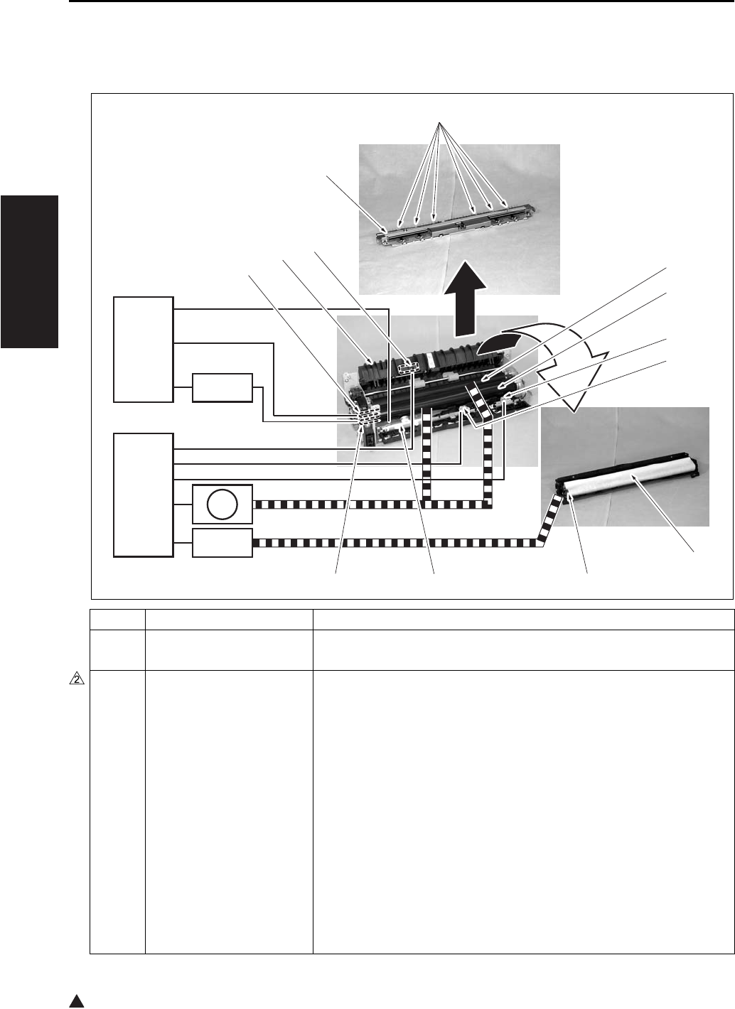
FIXING UNIT
2-24
II UNIT EXPLANATION
2
7. FIXING UNIT
7.1 Composition
Symbol Name Function or method
[1] Fixing pressure roller Fixing of toner by pressure
Silicon rubber + PFA tube
[2] Fixing heat roller Toner fixing by means of heat
Aluminum + PFA coating
Temperature setting:
Idling: 376 to 369°F
While in copy operation - Other than when feeding paper by the
by-pass tray in the single sided copy mode: 381°F
While in copy operation - When feeding paper by the bypass tray
in the single sided copy mode (by selecting the type of paper)
• Thick paper mode 1: 381 + 50°F
• Thick paper mode 2: 381 + 50°F
• Thin paper: 381 - 50°F (Except the 7145)
• Other than the above: 381°F
Copying - 381 - 41°F, when a double sided copy is being made.
Low power mode: 185°F (can be changed in the 25 mode)
[8] [7] [6]
[5]
[4]
[3]
[2]
[1]
[13]
[12]
[11]
[10]
[9]
CB
DCPS
SD4
M11
FCB

FIXING UNIT
2-25
II UNIT EXPLANATION
[3] TH2 (Fixing temperature
sensor/2)
Detection of temperature at the edge (front side) of the fixing heating
roller
Contact type
[4] TH1 (Fixing temperature
sensor/1)
Detection of temperature at the center of the fixing heating roller
Contact type
[5] Cleaning web Cleaning of the fixing heat roller
Web wind-up method
[6] Fixing cleaning roller Tension pressure on the cleaning web
Spring pressure
[7] TS (Thermostat) Protection of the fixing heat roller against high temperature abnor-
mality (about 428°F)
Contact type
[8] L3 (Fixing heater lamp/2) Heating of the fixing heat roller (Sub)
AC drive
[9] L2 (Fixing heater lamp/1) Heating of the fixing heat roller (Main)
AC drive
[10] Fixing guide Paper conveyance guide, pressure/release of the fixing pressure
roller
[11] PS2 (Fixing exit sensor) Detection of paper at the fixing unit exit
Photosensor + actuator
[12] Neutralizing brush Neutralizing of paper that is exited
Neutralizing by means of a brush
[13] Fixing claw Separation of paper from the fixing heat roller
Spring pressure type (6 pcs.)
M11 Fixing motor Driving of the fixing heat roller and the ADU conveyance roller/1
DC brushless motor, PLL control
SD4 Cleaning web solenoid Driving of the cleaning web
24V drive
FCB Fixing control board Prevention of noise leak in the drive power for L3 (Fixing heater lamp
/2)
220V system only
Symbol Name Function or method
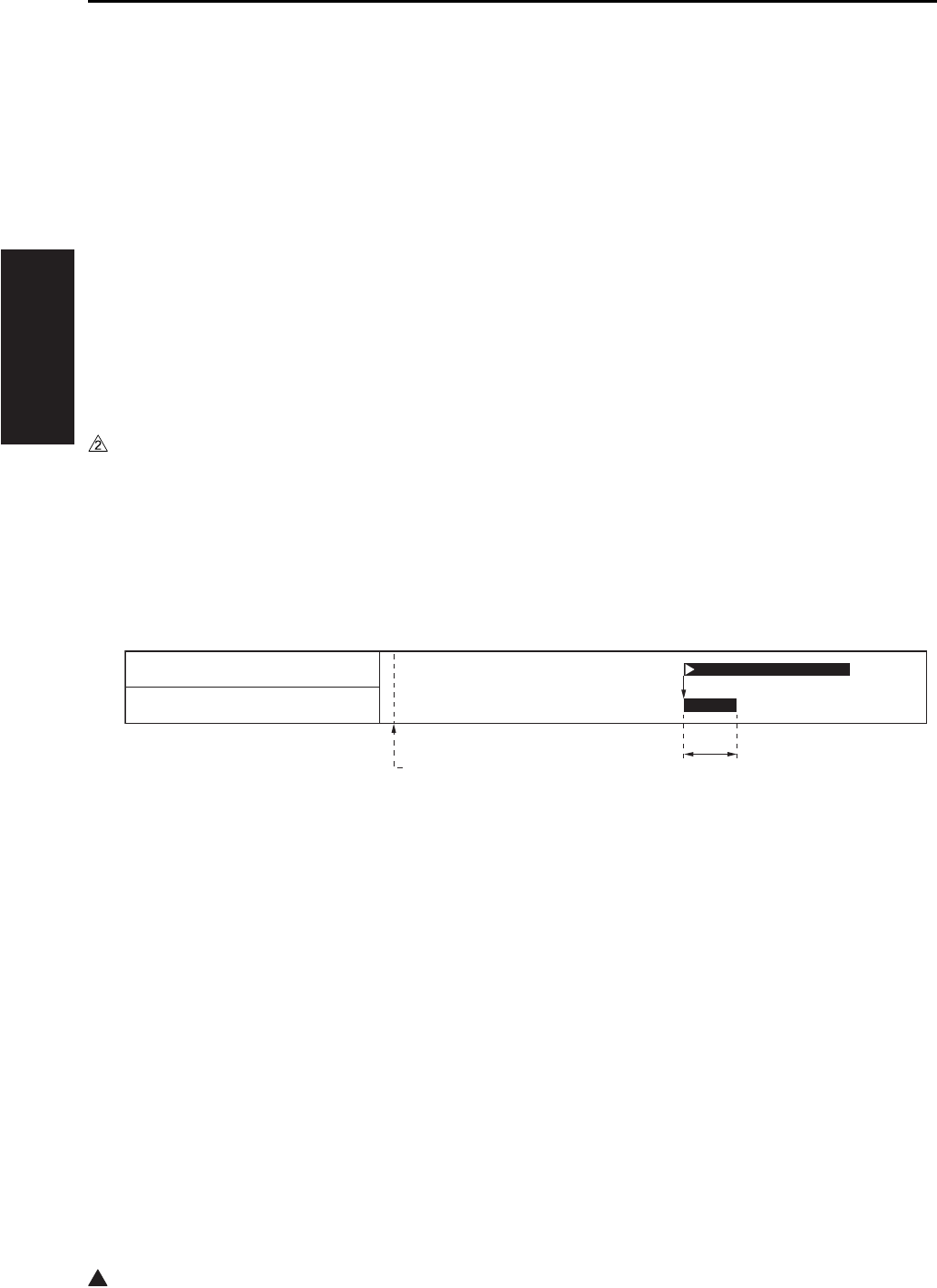
FIXING UNIT
2-26
II UNIT EXPLANATION
2
7.2 Operation
7.2.1 Fixing temperature control
The CB (Main body control board) uses the TH1 (Fixing temperature sensor/1) and the TH2 (Fixing tem-
perature sensor/2) to detect the temperature of the fixing heating roller, and turns on and off the L2 (Fixing
heater lamp/1) and the L3 (Fixing heater lamp/2) separately through the DCPS (DC power source) to
maintain both the TH1 and the TH2 at the specified temperature.
A. Warm-up
The CB (Main body control board) turns on the fixing heater lamp circuit within the DCPS (DC power
source) immediately after the SW2 turns on, and keeps the L2 (Fixing heater lamp/1) and L3 the (Fix-
ing heater lamp/2) turned on until the fixing heat roller reaches the specified temperature.
Once warm-up has completed, the CB switches the L2 and the L3 on and off so that the fixing heat
roller can be maintained to the set temperature for idling.
• Warm-up time: 30 seconds or less (at the room temperature of 68°F) (7145)
• Warm-up time: 19 seconds or less (at the room temperature of 68°F) (7235/7228/7222)
7.2.2 Cleaning web control
For each output of paper, the cleaning web is let off to be wound up.
The SD4 (Cleaning web solenoid) turns on based on the output of the PS2, causing the cleaning web to be
driven to start a wind-up operation.
[1] START button (ON) [2] 100 msec
[1] [2]
PS2 (Fixing exit sensor)
SD4 (Cleaning web solenoid)
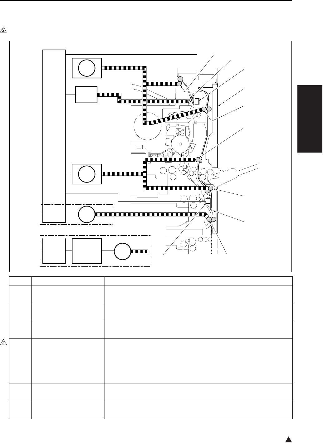
ADU/PAPER EXIT SECTION
2-27
II UNIT EXPLANATION
2
8. ADU/PAPER EXIT SECTION
8.1 Composition
Symbol Name Function or method
[1] PS2 (Fixing exit sensor) Detection of paper at the fixing unit exit
Photosensor + actuator
[2] ADU unit (ADU door) Paper conveyance while in double sided copy
Jam removal while in double sided copy
[3] ADU conveyance roller/1 Paper conveyance through the ADU entrance
Motor drive
[4] Decurler roller (7145)
Conveyance roller (7235/
7228/7222)
Paper conveyance through the ADU intermediate section and the cor-
rection of paper curling (7145)
Paper conveyance through the ADU intermediate section (7235/7228/
7222)
Motor drive
[5] ADU conveyance roller/2 Paper conveyance through the ADU intermediate section
Motor drive
[6] Switching sheet Switching of conveyance path at the paper reverse section
Switching by means of the elasticity of the PET sheet
7322ma2004e
[7]
[6]
[5]
[4]
[3]
[2]
[1]
[10]
[9]
[8]
CB
CB
SD5
M9
ADUDB
M6
M6
M11
7235/7228/7222
7145

ADU/PAPER EXIT SECTION
2-28
II UNIT EXPLANATION
2
*1 Except the 7145
[7] ADU roller
Paper conveyance through the ADU exit and switching of the conveyance direction
Motor drive
[8] PS4 (ADU sensor) Detection of paper at the ADU exit
Photosensor + actuator
[9] Paper exit roller Paper exit
Motor drive
[10] Switching guide Switching of the paper exit path at the fixing unit exit
Solenoid drive
ADUDB
*1
ADU drive board Driving of the M6 (ADU motor)
M6 ADU motor Driving of the ADU motor
Stepping motor
M9 Paper feed motor Driving of the decurler roller (7145 only) and the ADU conveyance
rollers/2
DC brushless motor, PLL control
SD5 ADU gate solenoid Pressure and release of the switching guide
24VDC drive
M11 Fixing motor Driving of the paper exit roller
DC brushless motor, PLL control
Symbol Name Function or method
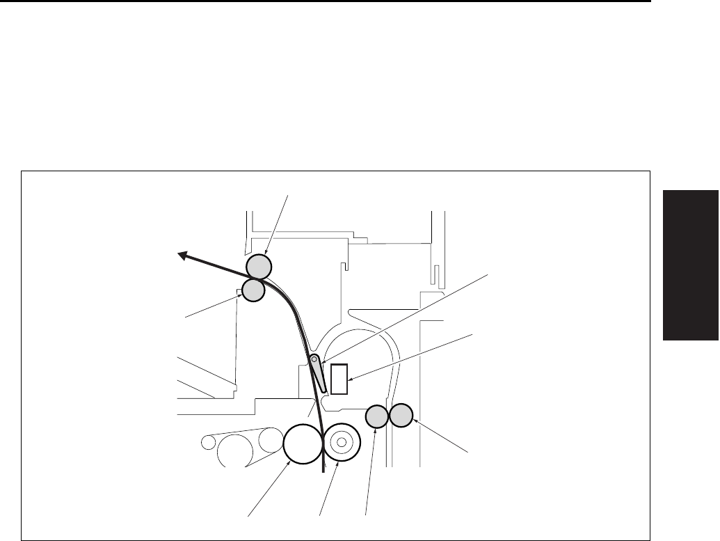
ADU/PAPER EXIT SECTION
2-29
II UNIT EXPLANATION
8.2 Operation
8.2.1 Switching control of the paper exit/ADU conveyance path
A. Straight paper exit path
The straight paper exit path is applicable when a single side is copied as well as after the back side
copy of paper is completed in the double sided copy mode.
[1] Switching guide (SD5 OFF) [5] Fixing pressure roller
[2] PS2 (Fixing exit sensor) [6] Fixing heat roller
[3] ADU conveyance driven roller/1 [7] Paper exit driven roller
[4] ADU conveyance roller/1 [8] Paper exit drive roller
[3]
[4][5][6]
[7]
[2]
[1]
[8]
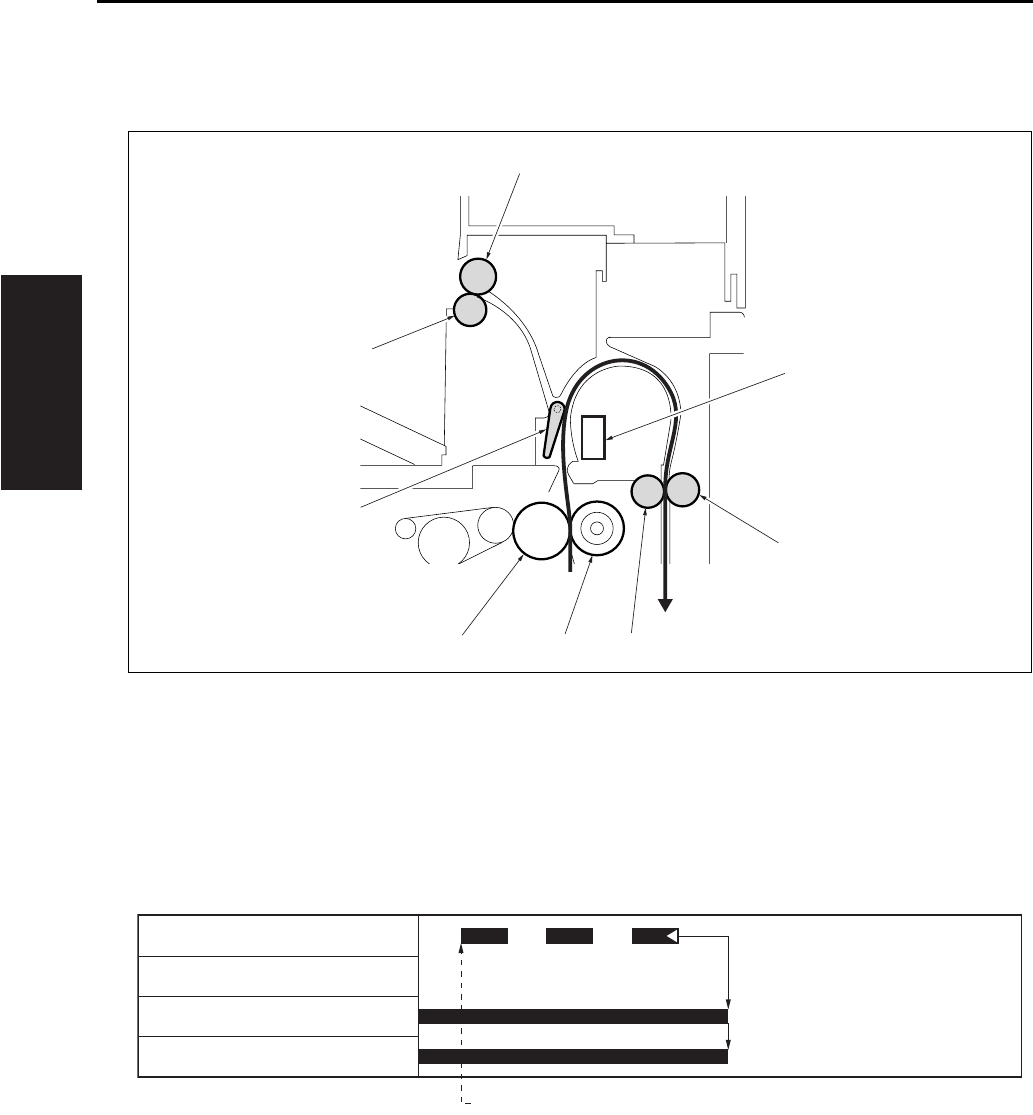
ADU/PAPER EXIT SECTION
2-30
II UNIT EXPLANATION
B. ADU conveyance path
The ADU conveyance path is applicable after the front side copy is completed in the double sided
copy mode.
C. Straight paper exit operation (single sided 3 copies)
[1] PS2 (Fixing exit sensor) [5] Fixing heat roller
[2] ADU conveyance driven roller/1 [6] Switching guide (SD5 ON)
[3] ADU conveyance roller/1 [7] Paper exit driven roller
[4] Fixing pressure roller [8] Paper exit drive roller
[1] 1st paper exit
[2]
[3][4][5]
[7]
[1]
[6]
[8]
[1]
PS2 (Fixing exit sensor)
SD5 (ADU gate solenoid)
M1 (Main motor)
M11 (Fixing motor)

ADU/PAPER EXIT SECTION
2-31
II UNIT EXPLANATION
2
D. ADU conveyance operation (double sided 3 copies)
8.2.2 ADU conveyance control
When a sheet of paper, the front of which has been printed in the double sided mode is conveyed to the
ADU unit, it is further conveyed to the ADU roller by the decurler roller (7145) or conveyance roller (except
the 7145) and the ADU conveyance rollers/2 which are in turn driven by the M9 (Paper feed motor).
[1] 1st paper exit for the front side [2] 1st paper exit for the back side
7322ma2005
[2][1]
MC2 (Loop clutch)
PS2 (Fixing exit sensor)
SD5 (ADU gate solenoid)
M1 (Main motor)
M11 (Fixing motor)
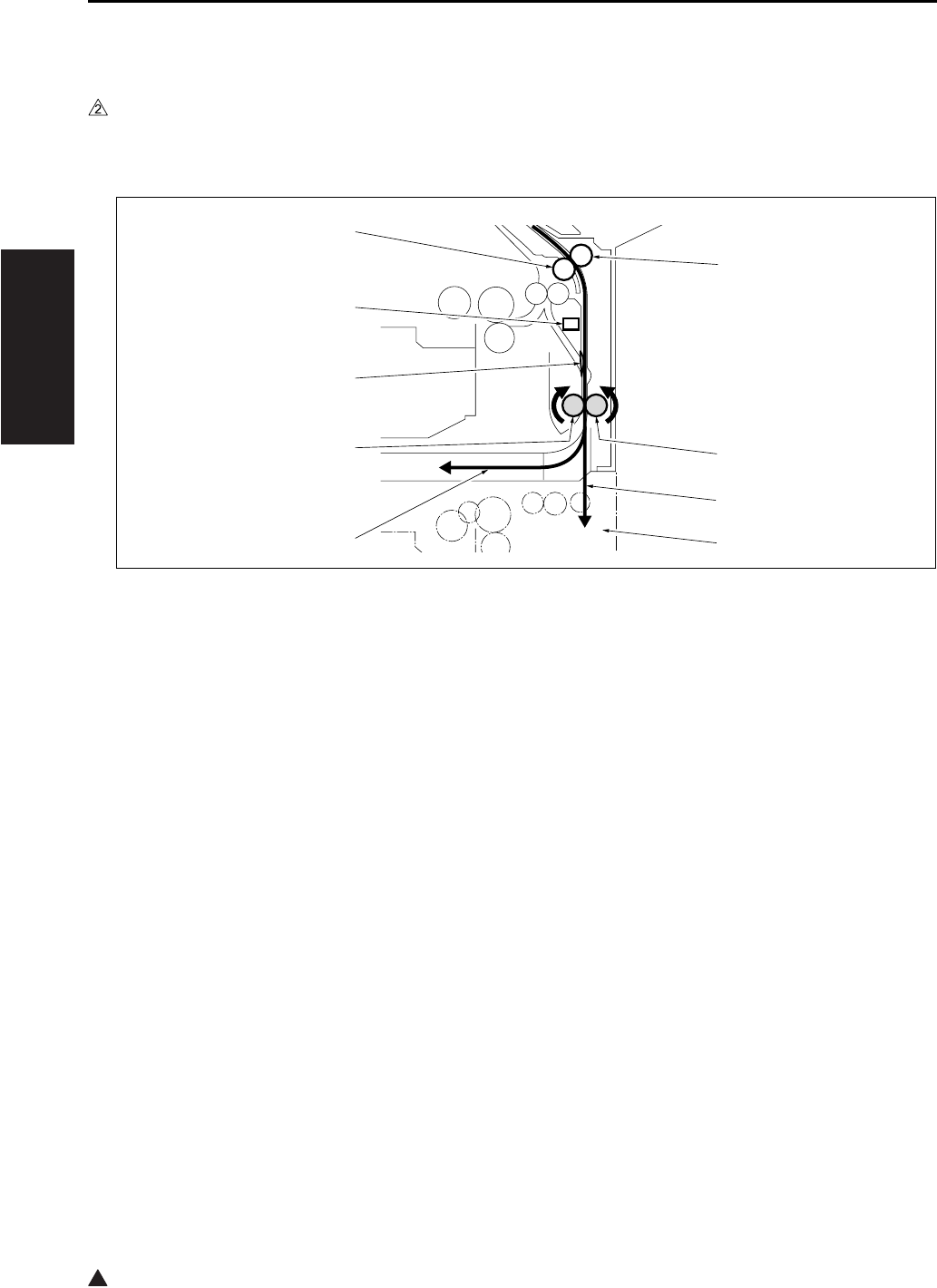
ADU/PAPER EXIT SECTION
2-32
II UNIT EXPLANATION
2
8.2.3 Paper reverse control
A. Paper reverse path
(1) When conveying paper
When a sheet of paper is conveyed from the ADU conveyance roller/2, it is further conveyed to the
ADU roller by pushing the switching sheet open.
[1] ADU conveyance driven roller/2 [6] ADU roller
[2] ADU driven roller [7] Switching sheet
[3] Conveyance path when DB is provided [8] PS4 (ADU sensor)
[4] DB [9] ADU conveyance roller/2
[5] Conveyance path when DB is not provided
7322ma2006
[4]
[3]
[6]
[5]
[7]
[8]
[9]
[2]
[1]
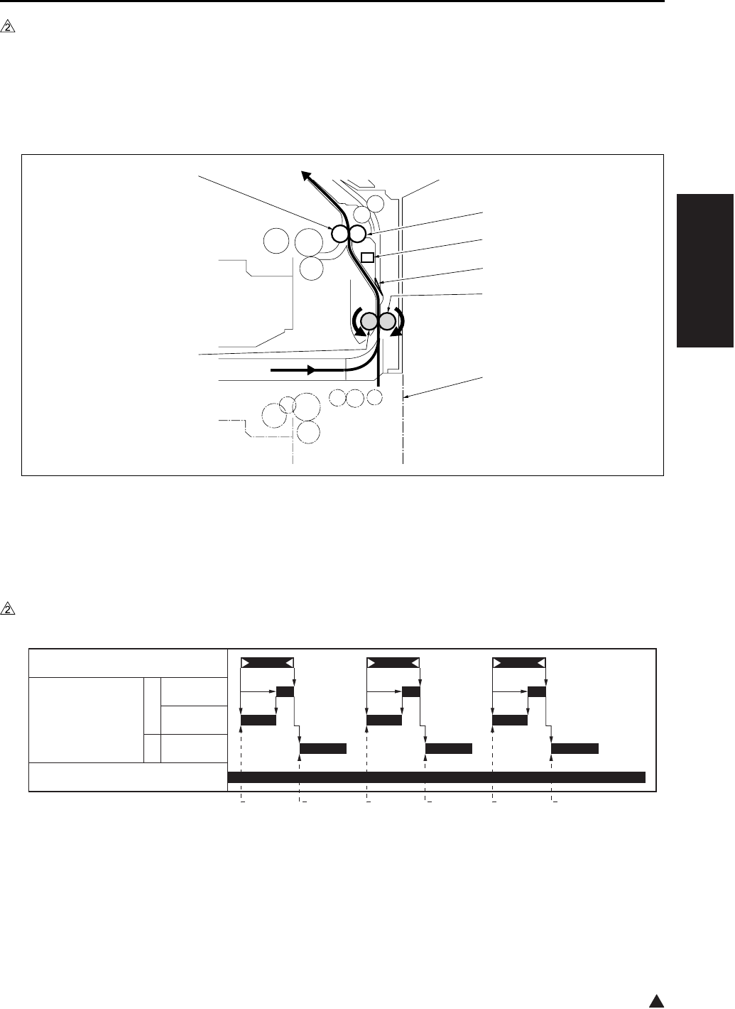
ADU/PAPER EXIT SECTION
2-33
II UNIT EXPLANATION
2
(2) When paper reverse
Paper that has been conveyed is sent back by means of the reverse rotation of the ADU roller. At this
time, the switching sheet uses its own elastic power to block the conveyance path to the ADU convey-
ance roller/2, and the paper is conveyed to the loop roller of the tray 2. As a result, the paper is turned
inside out to be copied on the back side after passing through the same route as that for the paper
sent from the tray 2.
B. Paper reverse operation (7145)
[1] Loop roller [5] DB
[2] PS4 (ADU sensor) [6] ADU roller
[3] Switching sheet [7] ADU conveyance roller/2
[4] ADU driven roller
[1] Start of 1st paper conveyance [4] Start of reverse operation of 2nd paper
[2] Start of revere operation of 1st paper [5] Start of 3rd paper conveyance
[3] Start of 2nd paper conveyance [6] Start of reverse operation of 3rd paper
7322ma2007
[7]
[2]
[3]
[4]
[5]
[1]
[6]
[1] [2] [3] [4] [5] [6]
PS4 (ADU sensor)
M6 (ADU motor) F
R
M9 (Paper feed motor)
600mm/s
230mm/s
230mm/s

ADU/PAPER EXIT SECTION
2-34
II UNIT EXPLANATION
2
C. Paper reverse operation (7235/7228/7222)
*1 165mm/s (7235) 140mm/s (7228/7222)
[1] Start of 1st paper conveyance [4] Start of reverse operation of 2nd paper
[2] Start of revere operation of 1st paper [5] Start of 3rd paper conveyance
[3] Start of 2nd paper conveyance [6] Start of reverse operation of 3rd paper
7322ma2013
[1] [2] [3] [4] [5] [6]
PS4 (ADU sensor)
M6 (ADU motor) F
R
M9 (Paper feed motor)
600mm/s
*1
*1
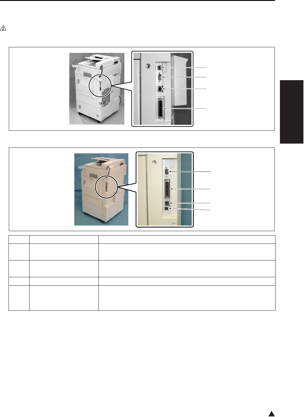
INTERFACE SECTION
2-35
II UNIT EXPLANATION
2
9. INTERFACE SECTION
9.1 Composition
In the case of the 7145
In the case of the 7235/7228/7222
Symbol Name Function or method
[1] Serial port (USB TypeB) For ISW of copier/FAX, For serial output of the printer
Ver. 1.1
[2] Serial port (RS-232C) For KRDS communication
D-SUB 9-pin connector
[3] RJ45 Ethernet port Port for network
[4] Parallel port
(IEEE1284 (Compatible,
Nible, ECP))
For ISW of copier/FAX/printer
For parallel output of the printer
36-pin parallel interface
[1]
[2]
[3]
[4]
7322ma2008
[2]
[3]
[4]
[1]

NETWORK SECTION
2-36
II UNIT EXPLANATION
10.NETWORK SECTION
10.1 Composition
Item Function name Function Purpose Remarks
TCP/IP service Arp {Obtain IP address
BootP {Obtain IP address
DHCP {Obtain IP address
DNS {Settle IP address
FTP Client {Scan to FTP
FTP Server {Scan to Box
IPP {Print Support Ver. 1.0
LPD/LPR {Print
Raw Socket {Print
Default port number = 9100
SMTP {Scan to Email
POP {For POP before SMTP
POP before SMTP {Authorization of SMTP
server access
HTTP 1.1 {WebUtility
SNMP v1
(SNMP over TCP)
{MIB access
SNMP v1
(
SNMP over IPX
)
{MIB access
Telnet X
SLP X
Netware service Bindery {Print
NDS (including simul-
taneous support of
Bindery)
{Print
• PServer mode {
•
RPrinter/NPrinter mode
{
NDPS
(
Gateway
)
{Print Corresponding in general
purpose Gateway
PCONSOLE /NWAD-
MIN, interchangeable
{
Frame Type (802.3, 8-
02.3, 802.3 SNAP,
Ethernet II)
{MAC frame corre-
sponding
AppleTalk service
EtherTalk PAP {Print
MS Network service
SMB over NetBEUI X Print
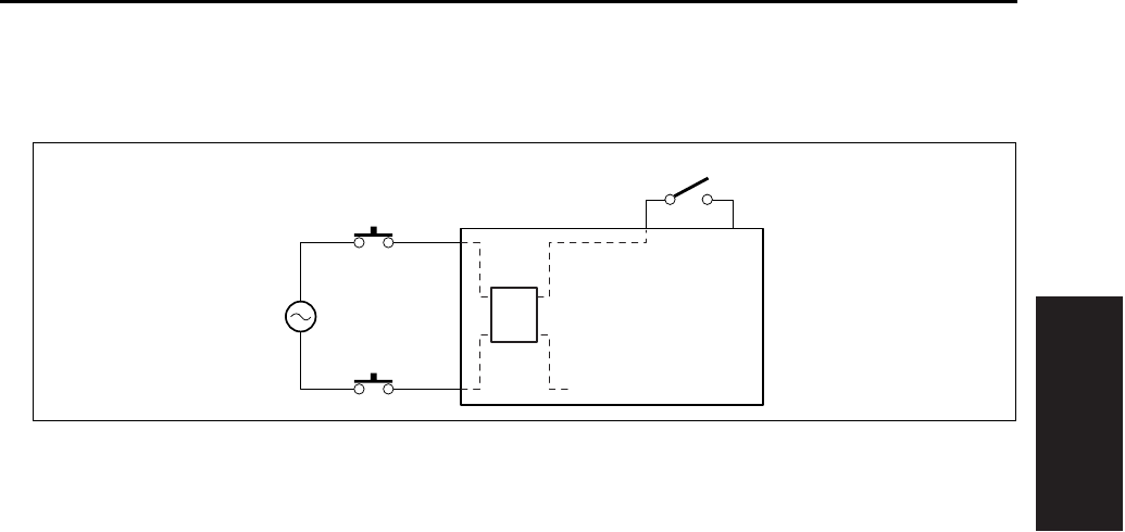
OTHER CONTROLS
2-37
II UNIT EXPLANATION
11. OTHER CONTROLS
11.1 Parts Energized When the Main Power Switch is OFF
The follwing components are powered regardless of whether the SW1 (Main power switch) is on or off,
provided that the power cord remains plugged in.
A. CBR 1 and CBR 2 (Circuit breakers/1 and /2)
The circuit breakers serve to protect internal components against damage from short circuit. If current
exceeds the specified value, the circuit breaker(s) will go off, cutting the power to the system.
B. NF (Noise filter)
This filter reduces noises that enter through the power line.
C. DCPS (DC power source)
This supplies power to each unit, and also controls the ON/OFF state of the fixing heater lamp.
SW1
DCPS
NF
AC(H)
AC(N)
CBR1
CBR2

OTHER CONTROLS
2-38
II UNIT EXPLANATION
2
11.2 Components Operated When the Power Switch is ON
11.2.1 Components operated when the SW1 (Main power switch) is on
In the case of the 7145
Setting the SW1 (Main power switch) to the ON position supplies AC power to the DCPS (DC power
source) which in turn supplies +12DVC, -12VDC, and +5DVC to the SCB (System control board). The
DCPS also supplies +5DVC to the OB (Operation board) through the SCB.
When the PTC (Internal heater) is provided as an option for service parts, according to the setting of the
25 mode DIP SW16-2, +24VDC is supplied to the PTC (Heater) from the DCPS (DC power source).
If options such as a printer controller (IP-432) and/or fax control board (FK-102 Type A/FL-102) are
installed, +12VDC, -12VDC and +5VDC are also supplied to these options through the SCB (System con-
trol board).
In the automatic start-up mode, the same operation is made consecutively as when the SW2 (Sub power
switch) is turned on according to the discretion of the SCB (System control board).
7322ma2009
SW1
DCPS
SCB
PTC
(OPTION)
OB
IP-432
(OPTION)
+12VDC
-12VDC
+5VDC
+24VDC
+12VDC
-12VDC
PSW2B
SW2
+5VDC
SGND
+5VDC
+12VDC
-12VDC
+5VDC
+12VDC
-12VDC
+5VDC
SUB_SW
FK-102/FL-102
(OPTION)
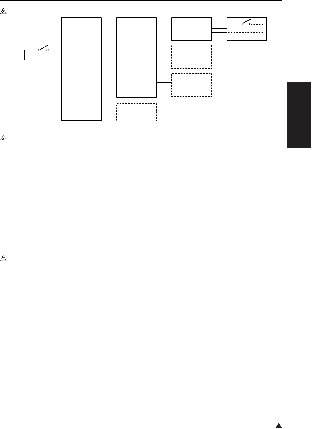
OTHER CONTROLS
2-39
II UNIT EXPLANATION
2
In the case of the 7235/7228/7222
Setting the SW1 (Main power switch) to the ON position supplies AC power to the DCPS (DC power
source) which in turn supplies +12DVC and +5DVC to the SCB (System control board). The DCPS also
supplies +5DVC to the OB (Operation board) through the SCB.
When the PTC (Internal heater) is provided as an option for service parts, according to the setting of the
25 mode DIP SW16-2, +24VDC is supplied to the PTC (Heater) from the DCPS (DC power source).
If options such as a printer controller (IP-424) and/or fax control board (FK-103/FL-103) are installed,
+12VDC and +5VDC are also supplied to these options through the SCB (System control board). How-
ever, when the LAN cables are not connected with none of these options provided, a part of the section
within the SCB (System control board) is not supplied with +5 VDC.
In the automatic start-up mode, the same operation is made consecutively as when the SW2 (Sub power
switch) is turned on according to the discretion of the SCB (System control board).
11.2.2 Components operated when the SW2 (Sub power switch) is on
The SW2 (Sub power switch) is located on the PSW2B (Power SW2 board). Upon the SW2 on, an ON sig-
nal is sent from the SW2 to the SCB (System control board) through the OB (Operation board). As a result,
the SCB sends a control signal to the DCPS (DC power source), thus causing the DCPS to supply
+12VDC, -12VDC (7145 only) and +5VDC to all of the boards and options, including the CB (Main body
control board).
The SCB (System control board) then sends to the DCPS (DC power source) a control signal that causes
the DCPS to generate +24VDC. This 24VDC power is supplied to all of the drive boards and options.
7322ma2021
SW1
DCPS
SCB
PTC
(OPTION)
OB
IP-424
(OPTION)
+12VDC
+5VDC
+24VDC
PSW2B
SW2
+5VDC
SGND
+12VDC
+5VDC
+12VDC
+5VDC
+12VDC
+5VDC SUB_SW
FK-103/FL-103
(OPTION)
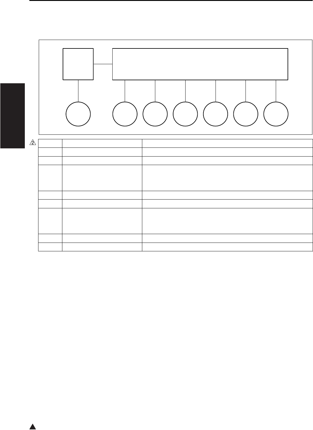
OTHER CONTROLS
2-40
II UNIT EXPLANATION
2
11.3 Fan Control
11.3.1 Composition of the cooling fan
*1 7145/7235 only
*2 7145 only
*3 7235 only
Symbol Name Function or method
FM1 DC power supply cooling fan Cooling of the DCPS (DC power source)
FM2*1 Fixing cooling fan Preventing the ends of the fixing roller from getting overheated
FM3 Internal dehumidifying fan/1 Prevention of internal dew condensation, removal of internal
ozone, and prevention against internal temperature getting too
high
FM4 Internal cooling fan/1 Cooling of the drum unit, the write unit and their surroundings
FM5 Developing suction fan Prevention against scattering of toner around the developing unit
FM6 Internal dehumidifying fan/2 Prevention of internal dew condensation, removal of internal
ozone, and prevention against internal temperature getting too
high
FM7*2 Internal cooling fan/2 Cooling of the interior of the developing unit
FM7*3 Polygon cooling fan Cooling of the M5 (Polygon motor)
FM2FM1
DCPS CB
FM3 FM4 FM5 FM6 FM7
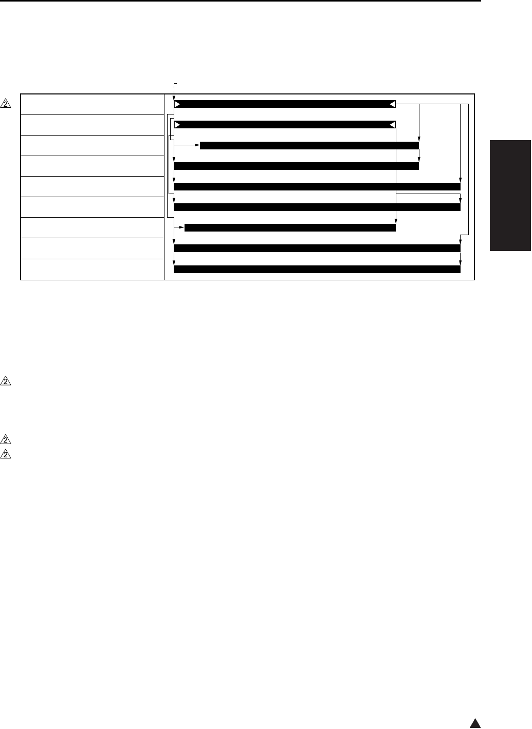
OTHER CONTROLS
2-41
II UNIT EXPLANATION
2
11.3.2 Fan operation
A. Operation of fans other than FM4 (Internal cooling fan/1)
*1 Operation for a small sized paper (such as B5R, A5R, B6R, postcard, 5.5 x 8.5R, 16KR). For paper
sizes other than these small ones, the fan turns on when the TH2 (Fixing temperature sensor/2)
detects a temperature above 417°F, and turns off when it gets below 408°F
*2 7145 only
In the case of the 7235/7228/7222, the operation of the fan, that is based on whether the M3 (Develop-
ing motor) turns ON or OFF while in the 7145, is based on whether the M1 (Main motor) turns ON or
OFF.
*3 7145 only
*4 7235 only
B. Operation of FM4 (Internal cooling fan/1)
(1) ON/OFF timing
The FM4 (Internal cooling fan/1) is turned on when the machine-inside temperature sensor provided
on the TCSB (Toner control sensor board) detects a temperature of 109°F, and turned off when the
temperature gets below 105°F.
(2) Abnormality detection
The internal temperature sensor installed on the TCSB (Toner control sensor board) detects a temper-
ature of 136°F, error code F22-1 is displayed on the operation unit and the machine is stopped.
[1] START button (ON)
7322ma2014
[1]
M1 (Main motor)
M3 (Developing motor)*2
FM1 (DC power source fan)
FM2 (Fixing cooling fan)*1
FM3 (Internal dehumidifying fan/1)
FM5 (Developing suction fan)
FM6 (Internal dehumidifying fan/2)
FM7 (Internal cooling fan/2)*3
FM7 (Polygon cooling fan)*4

OTHER CONTROLS
2-42
II UNIT EXPLANATION
2
11.4 Operation Unit Control
11.4.1 Composition of operation unit
Symbol Name Function or method
SW2 Sub power switch Power switch for the operating section
Does not function when the SW1 (Main power switch) is off.
PSW2B Power SW2 board LED packaging to display the on/off status of the SW1 (Main
power switch)
LCD LCD Use to display various information
LCDB Display board Backlight for the LCD
INV2 Display inverter Inverter used to drive the LCD (Display board)
PAKB Panel key board Touch switch board used to directly select items displayed on the
LCD
SP Speaker When an optional fax control board is installed, a monitor sound
on the line while a call is being made.
OB Operation board Used to control the PSW2B (Power SW2 board), the LCD (Dis-
play board), the INV2 (Display inverter) and the PAKB (Panel key
board), and also used to control the LED inside the OB and the
ten-key
SCB OB
LCD
LCDB
SP
(OPTION)
INV2
PAKB
PSW2B
SW2
SGND
SUB_SW

OTHER CONTROLS
2-43
II UNIT EXPLANATION
2
11.5 Counter Control
11.5.1 Counter composition
11.5.2 Counter operation
This machine uses the following two software counters to count the number of copies. However, the con-
tent of the number display counter on the OB (Operation board) may differ depending on the operating
condition of the machine.
A. Paper feed counter
This counter increments when the 1st paper feed for the next copy comes ON.
B. Paper exit counter
This counter increments when the PS2 (Fixing exit sensor) goes ON → OFF.
C. Number display counter on the OB (Operation board)
Symbol Name Function or method
OB Operation board Displays the number of copies by means of the LED.
TC Total counter
(7145 provided as a standard equipment)
(7235/7228/7222 optional)
Displays the total number of copies.
This is a mechanical counter driven by an electric signal.
KC Key counter (optional) A counter used to make copying unavailable after the
specified number of copies is counted
This is a mechanical counter driven by an electric signal.
PS2 Fixing exit sensor Detects paper at the fixing exit. This information
becomes a control signal source for each counter.
Photosensor + actuator
Normal operation Jam
Indicator shows a count from the paper feed counter. Indicator shows a count from the paper exit counter.
7322ma2011e
7145 7235/7228/7222
CB
SCB
TC
KC
(OPTION)
TC
(OPTION)
PS2
OB

OTHER CONTROLS
2-44
II UNIT EXPLANATION
Blank page
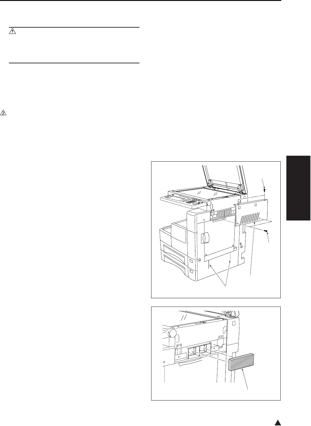
EXTERNAL SECTION
3-1
III DIS./ASSEMBLY
2
III DISASSEMBLY/ASSEMBLY
Caution:
• Make sure the power cord of the copier is
unplugged from the power outlet before dis-
assembly or assembly.
1. EXTERNAL SECTION
1.1 Replacing the Ozone Filter
A. Periodically replaced parts/cycle
• Ozone filter: Every 240,000 copies (7145)
• Ozone filter: Every 200,000 copies (7235/7228/
7222)
B. Procedure
1. Remove the 4 screws [1], and remove the scan-
ner exterior/R [2].
Note:
• If an unusual noise is emitted when you open or
close the bypass tray, clean the ADU door rib [3]
with alcohol.
2. Remove the ozone filter [1].
3. Reinstall the above parts following the removal
steps in reverse.
Note:
• When installing the ozone filter, take care not to
break it.
[1]
[1]
[3]
[2]
[1]
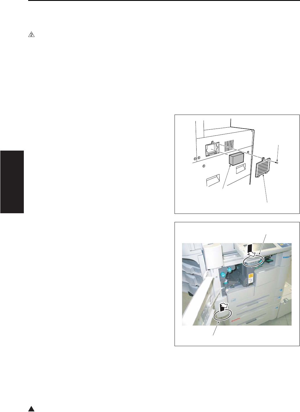
EXTERNAL SECTION
3-2
III DIS./ASSEMBLY
2
1.2 Replacing the Filter Cover
Assembly & Suction Filter/A
A. Periodically replaced parts/cycle
• Suction filter/A: Every 120,000 copies (7145)
• Suction filter/A: Every 100,000 copies (7235/
7228/7222)
• Filter cover assembly: Every 120,000 copies
(7145)
• Filter cover assembly: Every 100,000 copies
(7235/7228/7222)
B. Procedure
1. Remove the screw [1], then remove the filter
cover assembly [2].
2. Remove the suction filter /A [3].
3. Reinstall the above parts following the removal
steps in reverse.
Note:
• When installing the suction filter/A, be sure to
install it so that the white filter face is turned to the
inside of the main body.
Note:
• When an elevator tray unit is fitted, perform the
following to access the filter section.
• While pressing [1], lift up [2], and pull out the ele-
vator tray unit and the horizontal conveyance unit.
Do not remove the finisher.
To remove the finisher, see [III. DISASSEMBLY/
ASSEMBLY] of the finisher section.
[1]
[2]
[3]
[1]
[2] 7145ma3130
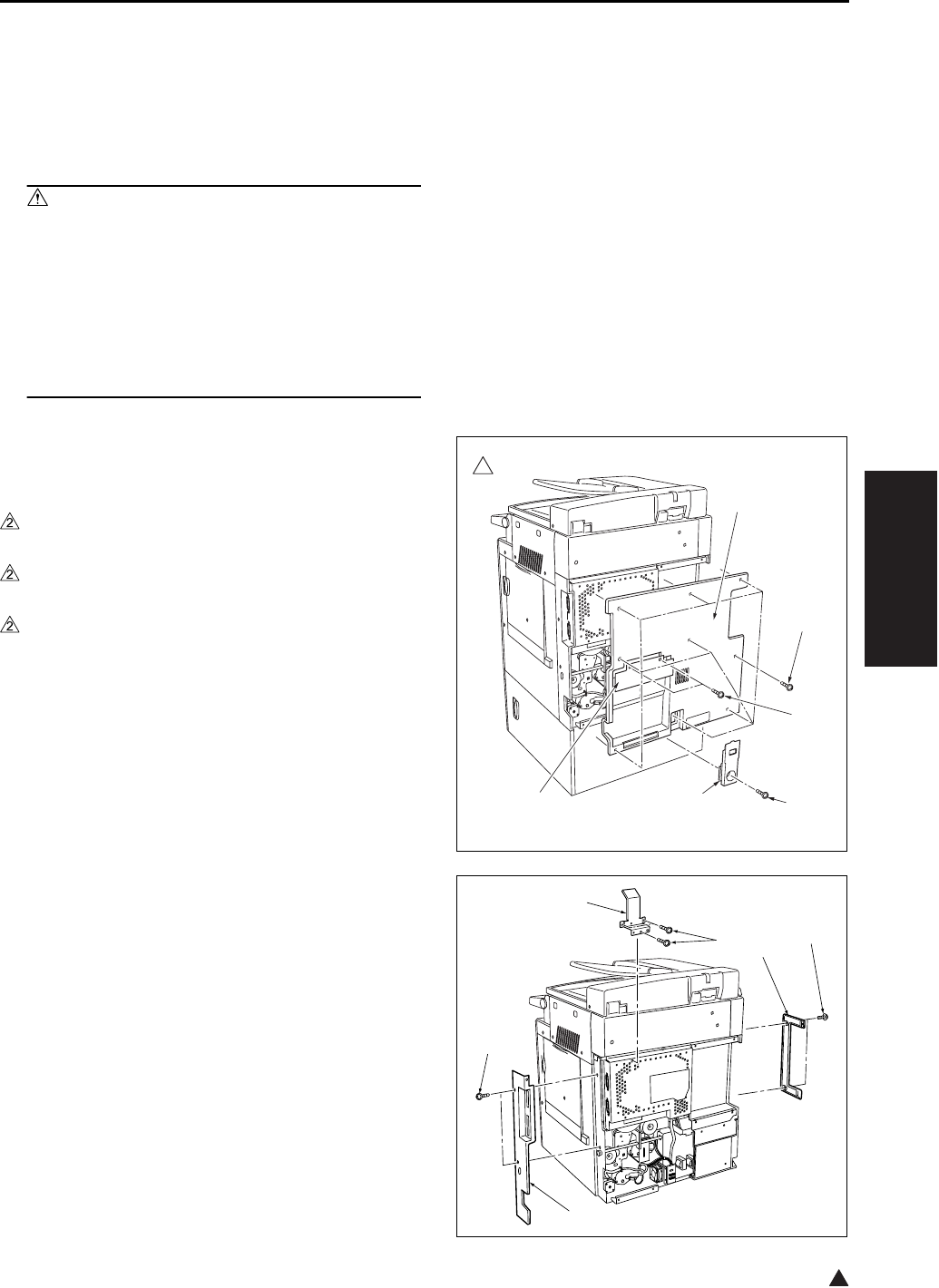
DRIVE SECTION
3-3
III DIS./ASSEMBLY
2
2. DRIVE SECTION
2.1 Removing and Reinstalling
the Motor Units (Main, Fix-
ing, Feed, Developing)
Caution:
• Be sure to remove the drum unit from the
main body before removing or reinstalling
the main motor unit. If the drum unit is in
place at this time, the drum will rotate when
you install or remove the drum rotating plate,
resulting in possible damage to the cleaning
blade.
A. Procedure
1. Remove the developing unit and drum unit from
the main body.
2. Remove the screw [1], and remove the cord
cover/B [2].
3. Remove the 2 screws [3], and remove the cord
cover/A [4].
4. Remove the 9 screws [5], and remove the rear
cover [6].
5. Remove the 2 screws [1], and remove the rear
cover/R [2], the rear cover/L [3].
6. Remove the 3 screws [4], and remove the wire-
bundle guide plate [5].
7322ma3001
2
[5]
[3]
[6]
[2][4] [1]
[3]
[4]
[5]
[1]
[2]
[1]

DRIVE SECTION
3-4
III DIS./ASSEMBLY
2
7. Remove the 15 screws [1], and remove the
board cover/D [2] (7145 only).
8. Remove the 13 screws [3], and remove the
board cover/A [4].
9. Remove the various wiring connectors from the
SCB (System control board) [1].
Note:
• Be very careful when handling the ribbon cable
connector from the SCB (System control board).
See “2.4 Removing the ribbon cable” and “2.5
Installing the ribbon cable”.
10. Remove the 12 screws [2] (7145) or the 11
screws [3] (7235/7228/7222), and remove the
system control board unit [4].
11. Disconnect the connectors from each motor unit
[1].
12. Remove the 4 screws [2], then remove each
motor unit [3], [4] (7145 only), [5].
13. Reinstall the above parts following the removal
steps in reverse.
[3]
[4]
[2]
[1]
[1]
7322ma3002
2
[2]
[2] [3] [4]
[1]
[2] [3]
[2] [3]
7322ma3003
2[1]
[1]
[1] [5]
[2]
[2]
[2]
[3]
[4]
[3]
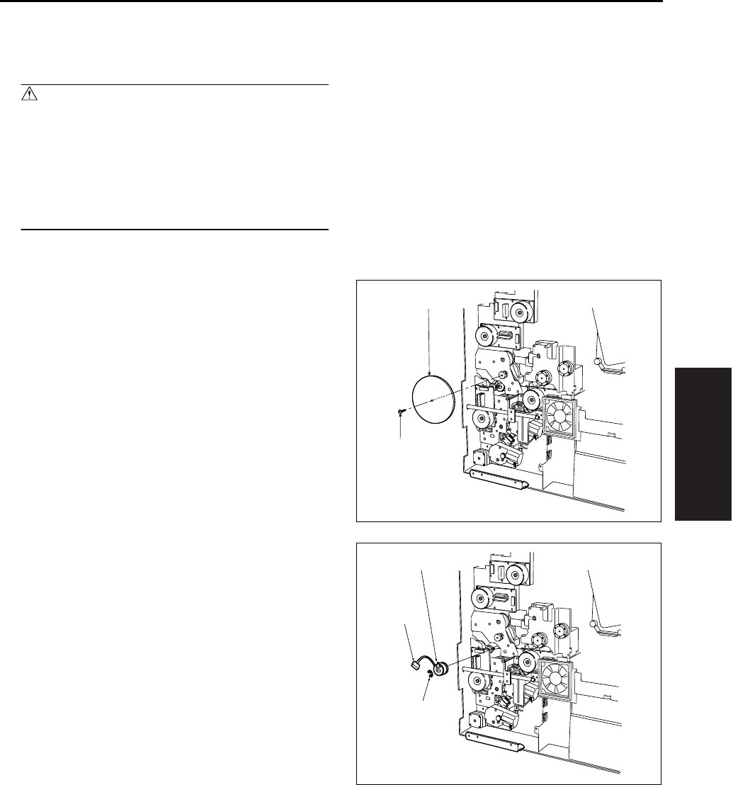
DRIVE SECTION
3-5
III DIS./ASSEMBLY
2.2 Replacing the Registration
Clutch
Caution:
• Be sure to remove the drum unit from the
main body before carry out the following pro-
cedure. If the drum unit is in place at this
time, the drum will rotate when you install or
remove the drum rotating plate, resulting in
possible damage to the cleaning blade.
A. Procedure
1. Remove the system control board unit.
• For removal procedure, see “2.1 Removing and
reinstalling the motor units (main, fixing, feed,
developing)”.
2. Remove the set screw [1], and remove the drum
rotating plate [2].
3. Remove the clutch connector [1].
4. Remove the E-ring [2]. Pull the registration
clutch [3] toward you and rotate it to remove.
[1]
[2]
[1]
[2]
[3]
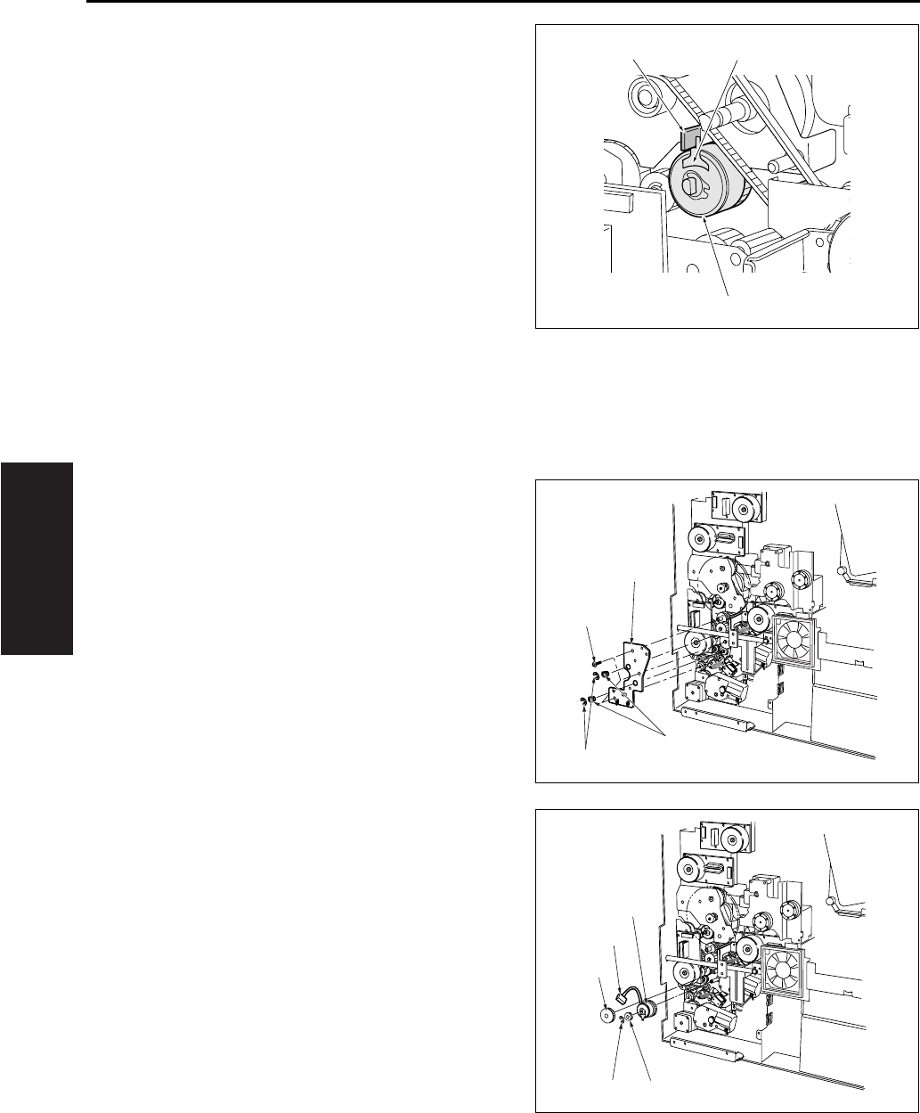
DRIVE SECTION
3-6
III DIS./ASSEMBLY
5. Reinstall the above parts following the removal
steps in reverse.
Note:
• When installing the registration clutch [1], be sure
to set the groove of the clutch detent in the stop-
per [3].
2.3 Replacing the Loop Clutch
A. Procedure
1. Remove the system control board unit.
• For removal procedure, see “2.1 Removing and
reinstalling the motor units (main, fixing, feed,
developing)”.
2. Remove the wire bundle from the clamp on the
conveyance drive panel [1].
3. Remove the 2 E-rings [2], 3 screws [3] and 2
bearing [4] , and remove the conveyance drive
panel [1]. (Do not remove the rotation preven-
tion screws on the clutch.)
4. Remove the E-ring [1], then remove the gear [2]
and the connector [3], remove the gear [4] at the
front, and then remove the clutch [5].
5. Reinstall the above parts following the removal
steps in reverse.
[1]
[2][3]
[1]
[2]
[3]
[4]
[1] [2]
[4]
[3]
[5]
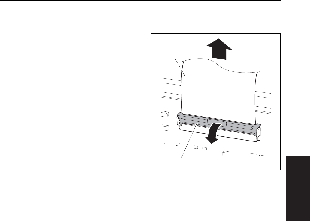
DRIVE SECTION
3-7
III DIS./ASSEMBLY
2.4 Removing the Ribbon Cable
A. Procedure
1. Move the lock lever [1] forward to release the
lock, then pull out the ribbon cable [2].
[1]
[2]
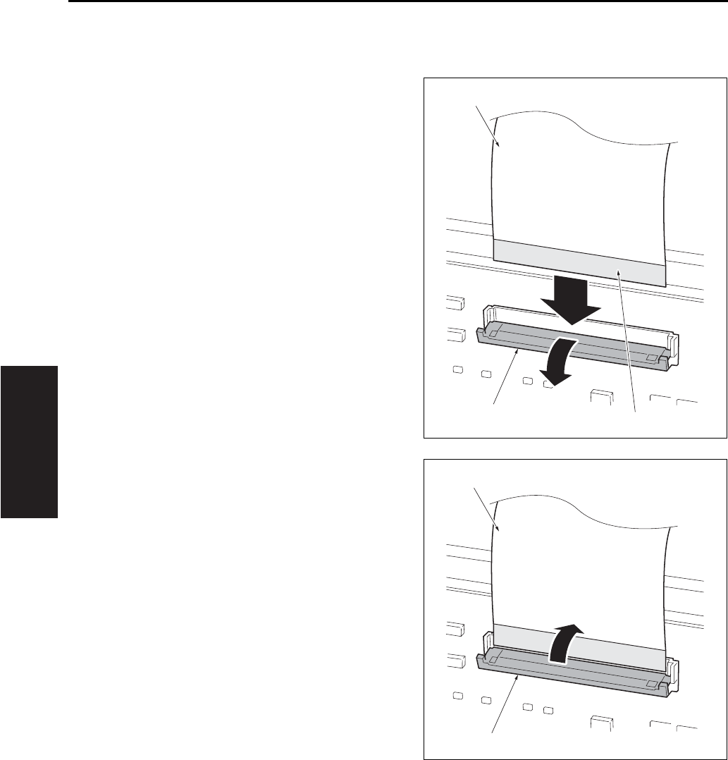
DRIVE SECTION
3-8
III DIS./ASSEMBLY
2.5 Reinstalling the Ribbon Cable
A. Procedure
1. Move the lock lever [1] forward, then insert the
ribbon cable [2] firmly into the connector while
ensuring that the conductive face of the ribbon
cable [3] is positioned on the opposite side of
the lock lever.
2. Push back the lock lever [1] to lock the ribbon
cable [2].
[1]
[2]
[3]
[1]
[2]
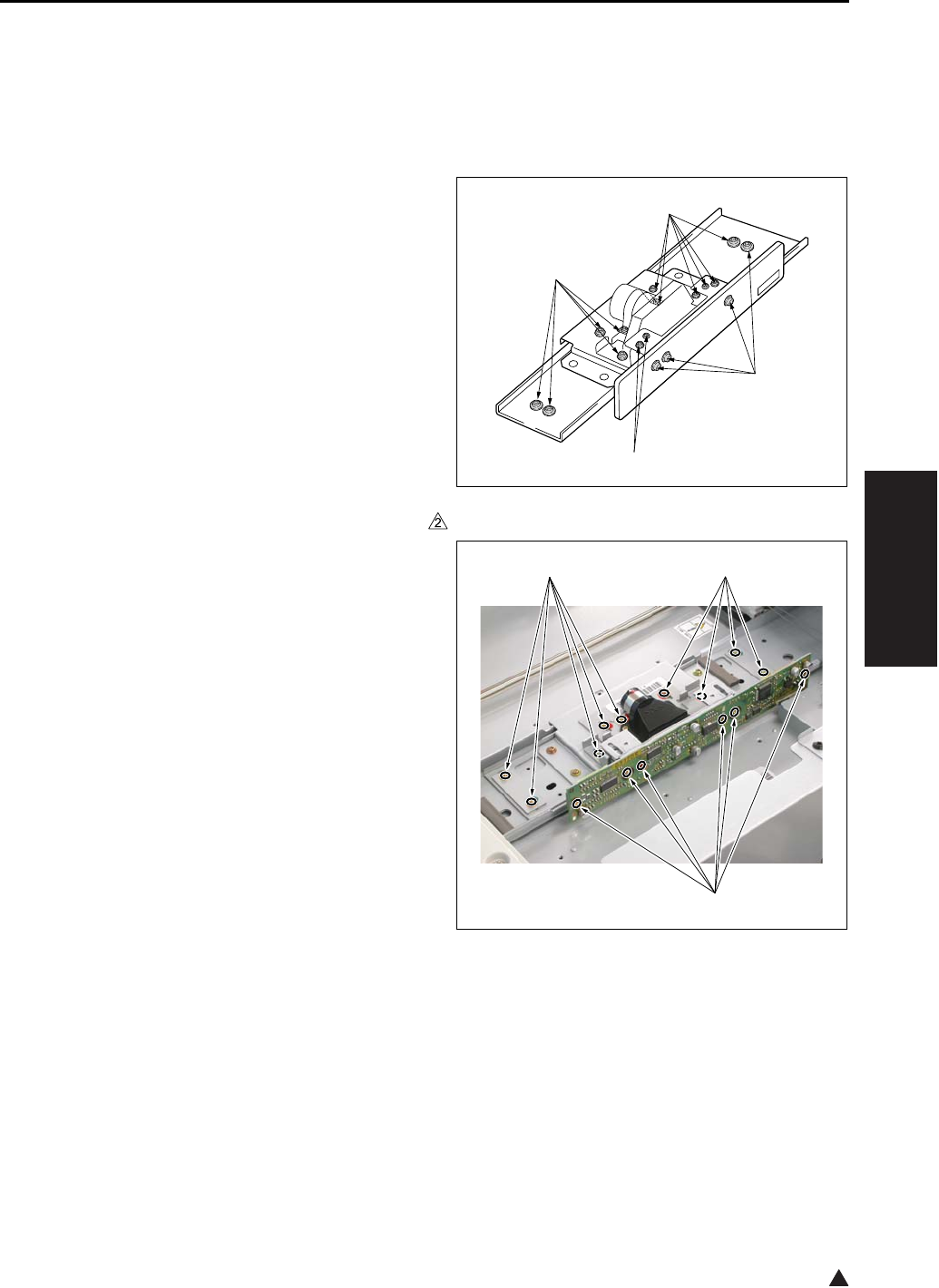
SCANNER SECTION
3-9
III DIS./ASSEMBLY
2
3. SCANNER SECTION
3.1 Screws That Must Not be
Removed
Note:
• The paint-locked screws [1] must not be
removed. Be sure that you do not remove these
screws.
In the case of the 7145
In the case of the 7235/7228/7222
[1]
[1]
[1]
[1]
[1] [1]
[1] 7322ma3004
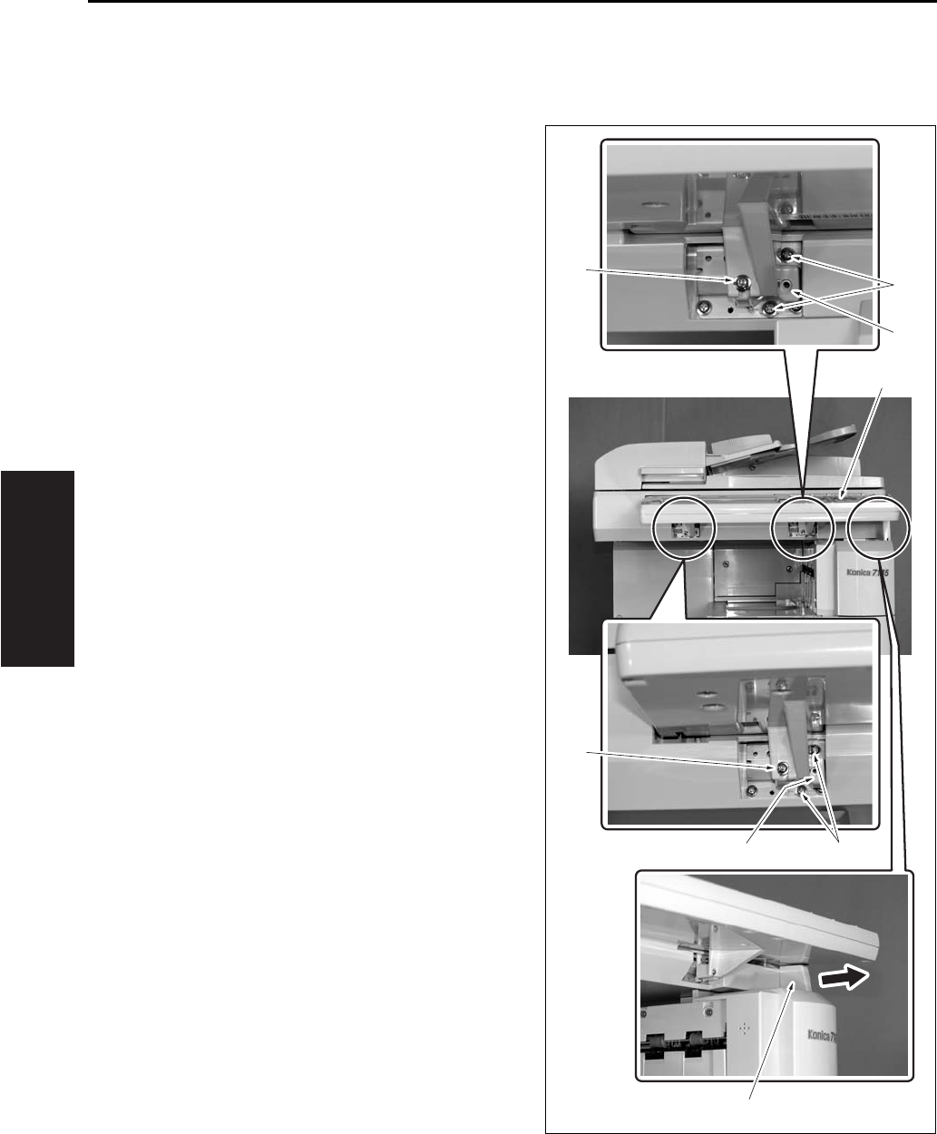
SCANNER SECTION
3-10
III DIS./ASSEMBLY
3.2 Adjusting the Angle of the
Operation Unit
A. Procedure
1. Remove the 2 screws [1].
2. Remove the operating section stopper [2].
3. Remove the 2 screws [3] for each position. And
then install the angle adjustment member [4] in
the specified position.
The angle adjustment member corresponds to 7
degrees for the right position and to 15 degrees
for the left position. However, this is not used for
the setting of 33 degrees.
4. Change the installation direction of the operat-
ing section stopper [2] and set it at the position
for 7 or 15 degrees. However, this is not used
for the setting of 33 degrees.
Note:
• The angle of the operation unit can be adjusted at
the following 3 stages: However, the setting at 33
degrees is available only when combined with the
paper exit tray.
5. Install the operating section stopper [2].
6. Fasten the operation unit [5] with the 2 screws
[1].
[1]
[1]
[3]
[4]
[2]
[4]
[3]
[5]
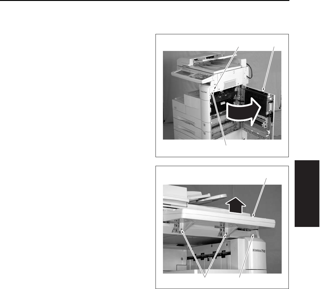
SCANNER SECTION
3-11
III DIS./ASSEMBLY
3.3 Removing the Operating Unit
A. Procedure
1. Open the ADU door [1].
2. Remove the screw [2] and remove the right side
cover /F [3].
3. Remove the 2 angle adjusting screws [1], and
remove the operating section stopper [3] while
lifting up the operating section [2].
[3]
[2] [1]
[2]
[3][1]
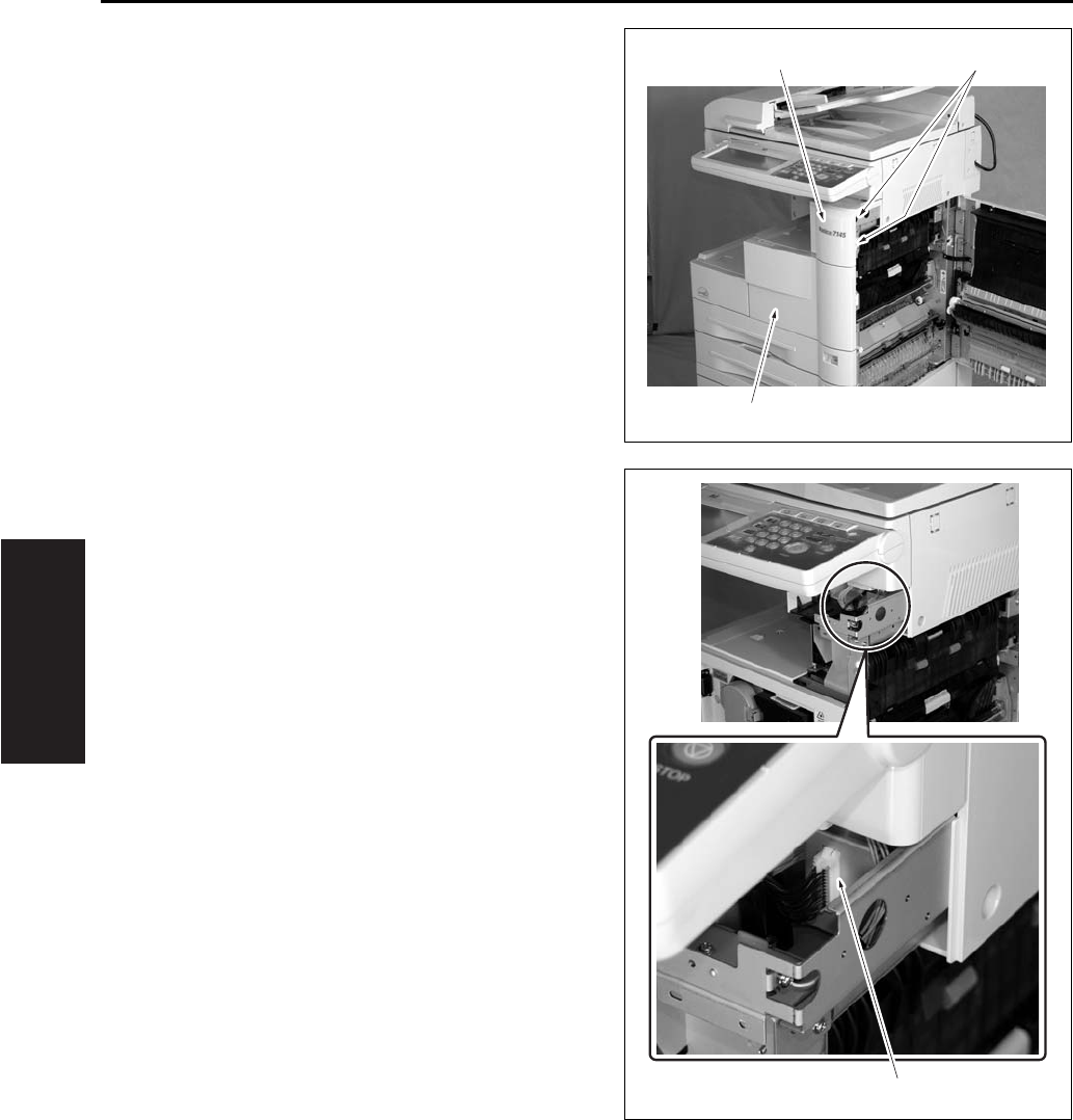
SCANNER SECTION
3-12
III DIS./ASSEMBLY
4. Loosen the 2 screws [1] and remove the front
cover [2] and the front door [3].
5. Remove the connector [1].
[1]
[2]
[3]
[1]
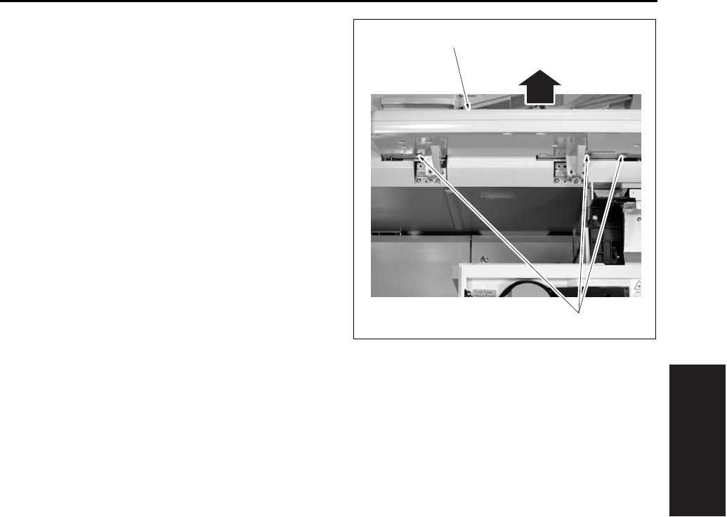
SCANNER SECTION
3-13
III DIS./ASSEMBLY
6. Remove the 3 screws [1], and remove the oper-
ating section [2] by pulling it out to this side.
7. Reinstall the above parts following the removal
steps in reverse.
[1]
[2]
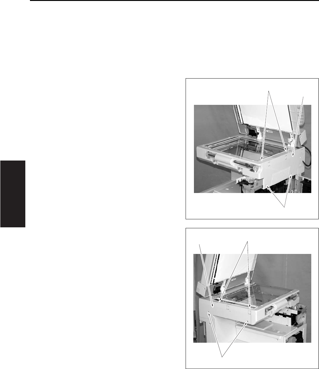
SCANNER SECTION
3-14
III DIS./ASSEMBLY
3.4 Removing the Platen Glass/
Slit Glass
When removing the platen glass, execute only the
steps 1, 3, 7, 8 and 9 in the following procedure. For
the slit glass, execute all of the steps 1 to 9.
A. Procedure
1. Open the RADF.
2. Remove the operation unit.
3. Remove the 4 screws [1] and remove the scan-
ner exterior/R [2].
4. Remove the 4 screws [1] and remove the scan-
ner exterior/L [2].
[1]
[1]
[2]
[1]
[1]
[2]
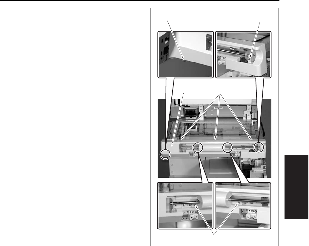
SCANNER SECTION
3-15
III DIS./ASSEMBLY
5. Remove the 7 screws [1] and remove the scan-
ner exterior/F [2].
[1][2]
[1][1]
[1]
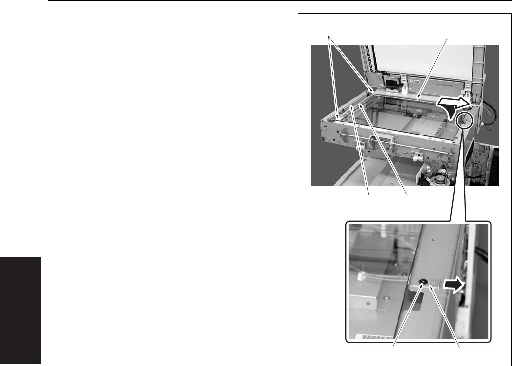
SCANNER SECTION
3-16
III DIS./ASSEMBLY
6. Remove the 2 screws [1] of the slit glass
pressure plate and remove the slit glass [2].
7. Loosen the screw [3] and slide the glass pressure
plate [4] to the paper feed side.
8. Lift up once the platen glass [5]. And then slide it
to the paper feed side to remove it.
Note:
• Be careful not to stain the white reference plate
attached to the back of the scale plate [6] pro-
vided on the paper feed side of the platen glass
[5].
• When the white reference plate gets smudged,
wipe it thoroughly with a clean cloth.
9. Reinstall the above parts following the removal
steps in reverse.
Note:
• When installing the platen glass [5], be sure to
fasten it securely while pressing the glass pressure
plate [4] to the platen glass [5].
• The slit glass is distinguished between the front
and the rear. Be sure to set the slit glass [2] so
that a black dot on its side comes in the rear right
side when you see the 7145 from the front side.
When attaching the slit glass holding plate with
the 2 screws [1], tighten these screws while
pressing the slit glass [2] onto the original glass
[5] side.
[5]
[1]
[3] [4]
[2] [6]
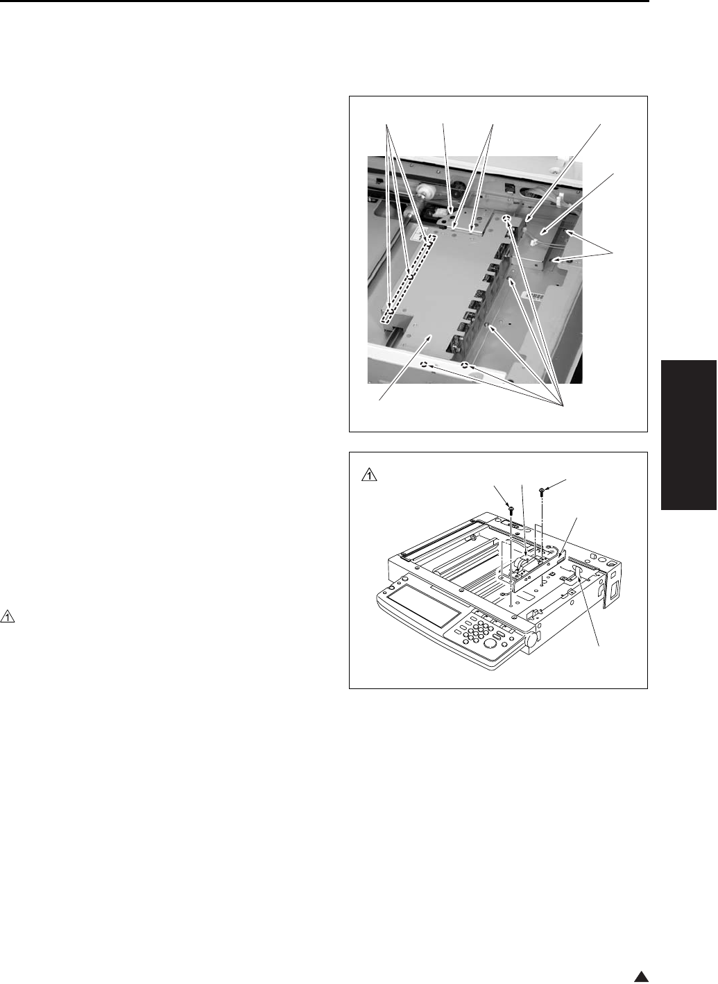
SCANNER SECTION
3-17
III DIS./ASSEMBLY
1
3.5 Removing and Reinstalling
the CCD Unit
A. Procedure
1. Remove the platen glass.
2. Remove the 2 screws [1], and remove the photo
sensor fastener [2].
3. Remove the 8 screws [3], and remove the lens
light blocking cover [4].
4. Remove the 3 screws [5], and remove the rib-
bon cable cover [6].
5. Remove the ribbon cable [2] from the ADB (A/D
conversion board) [1].
Note:
• Be careful to avoid damage to the ribbon cable
when removing it. When reinstalling it, be sure
that it is securely in place.
6. Remove the 4 screws [3], and remove the CCD
unit [4].
7. Reinstall the above parts following the removal
steps in reverse.
Note:
• Be sure to perform image adjustment after install-
ing the CCD unit. (See “I Adjustment” section.)
[1]
[2]
[3]
[6]
[5]
[5]
[3]
[4]
[1]
[2]
[3][3] [4]
7145ma3052
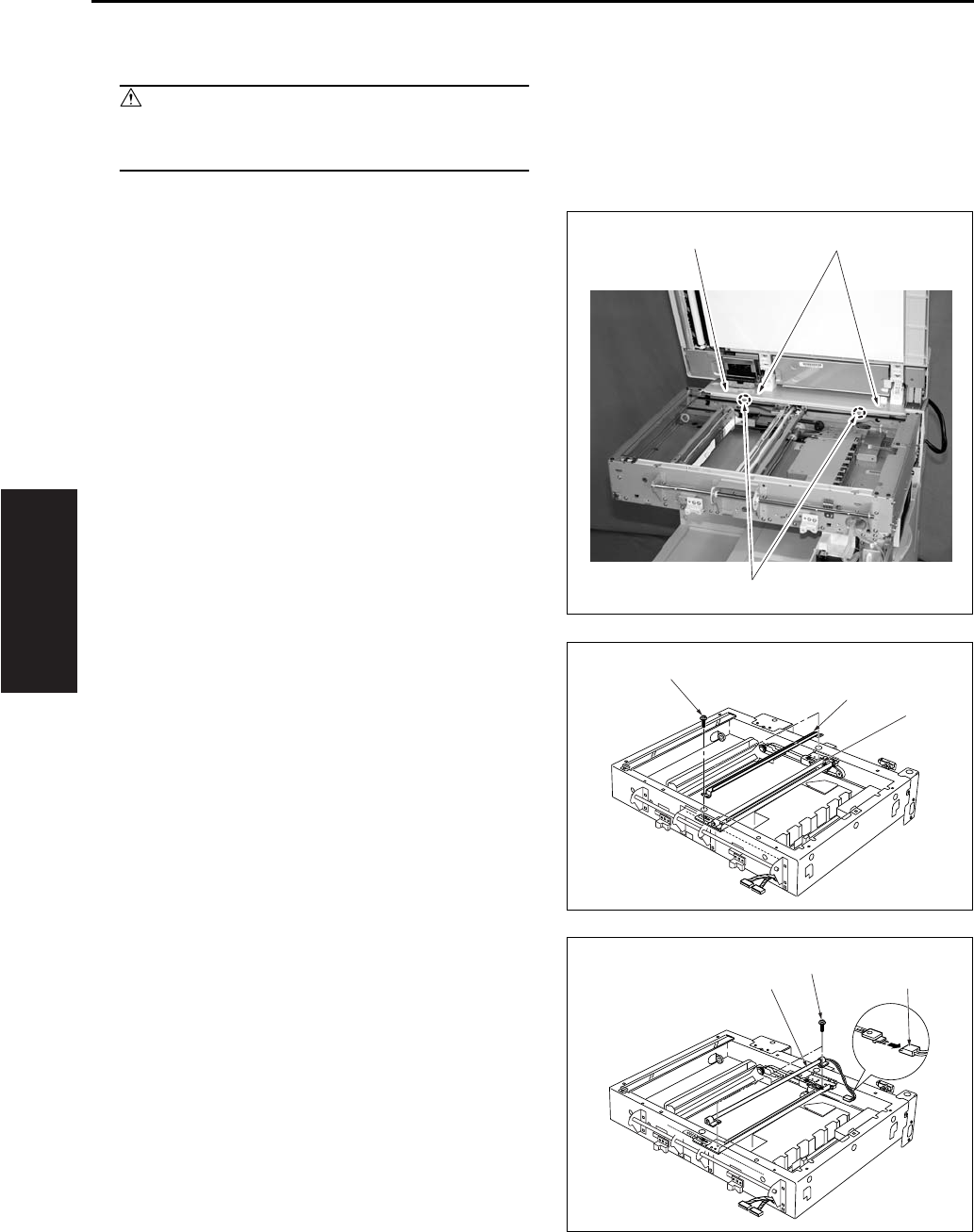
SCANNER SECTION
3-18
III DIS./ASSEMBLY
3.6 Replacing Exposure Lamp
Caution:
• Do not touch the exposure lamp's lamp area
with bare hands.
A. Procedure
1. Remove the RADF.
• For removing procedure, see the DF service
manual.
2. Remove the platen glass.
3. Remove the 4 screws [1], and remove the read
cover/R [2].
4. Shift the exposure unit [1] to the center of the
main body frame.
5. Remove the 2 screws [2], and remove the auxil-
iary reflecting mirror [3].
6. Remove the 1 connector [1] and 2 screws [2].
Tilt and remove the exposure lamp [3].
7. Reinstall the above parts following the removal
steps in reverse.
[1]
[2]
[1]
[1]
[2]
[3]
[1]
[2]
[3]
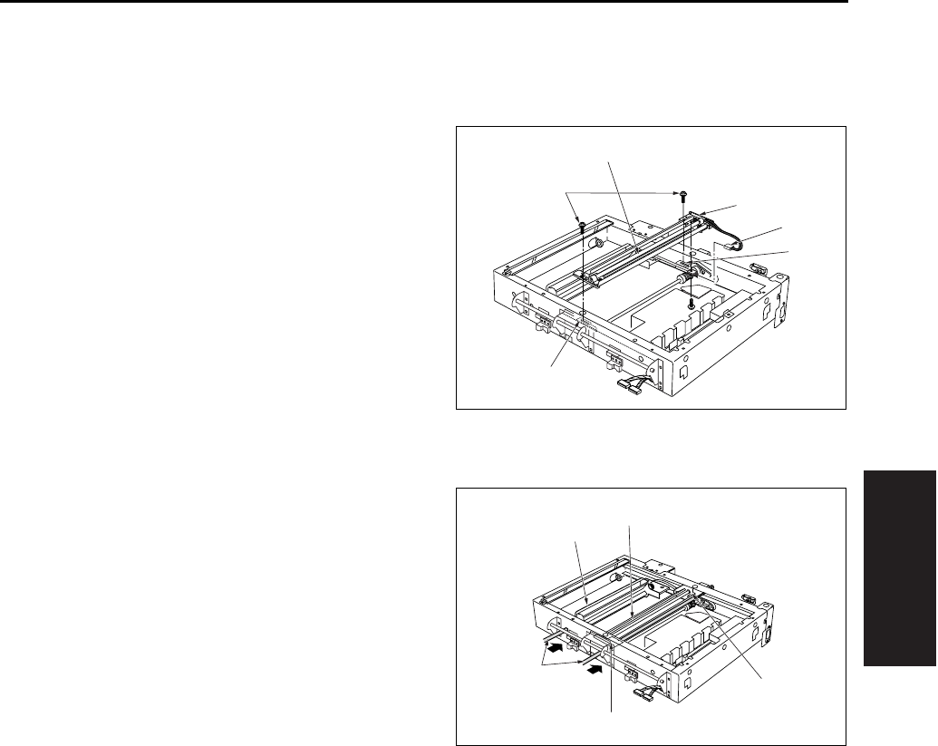
SCANNER SECTION
3-19
III DIS./ASSEMBLY
3.7 Removing and Reinstalling
the Exposure Unit
A. Removal procedure
1. Remove the RADF.
2. Remove the platen glass.
3. Remove the scanner cover/R.
4. Shift the exposure unit [1] to the center of the
main body frame.
5. The exposure unit [1] is fixed in place by set
screws fastened to the exposure unit mount fit-
tings/F [3], /R [4] (1 screw in each fitting).
Remove the 2 screws [2].
6. Tilt and slide the exposure unit [1] to remove it
from the frame.
7. Disconnect the exposure lamp [5] connector [6].
B. Installation procedure
1. Fit the exposure unit into the main body.
2. Insert the front exposure unit mount fitting/F [2],
/R [3] into the corresponding slits in the expo-
sure unit.
3. Shift the V mirror unit [4] to the exit side.
Through the front, insert the two optics unit posi-
tioning jig [5] so that they are at the installation
location for the exposure unit. Pass the jig [5]
through the V mirror unit [4] to fasten it in place.
Position the exposure unit [1] by pushing it
against the frame on the right side of the unit.
Note:
• Be sure to the use optics unit positioning jig when
reinstalling the exposure unit.
4. Fasten the exposure unit mount fittings/F, /R
into place (1 screw in each fitting).
5. Remove the optics unit positioning jig.
6. Finish installation by reversing the sequence of
the removal procedure.
[1]
[2]
[3]
[6]
[5]
[4]
[1]
[2]
[3]
[4]
[5]
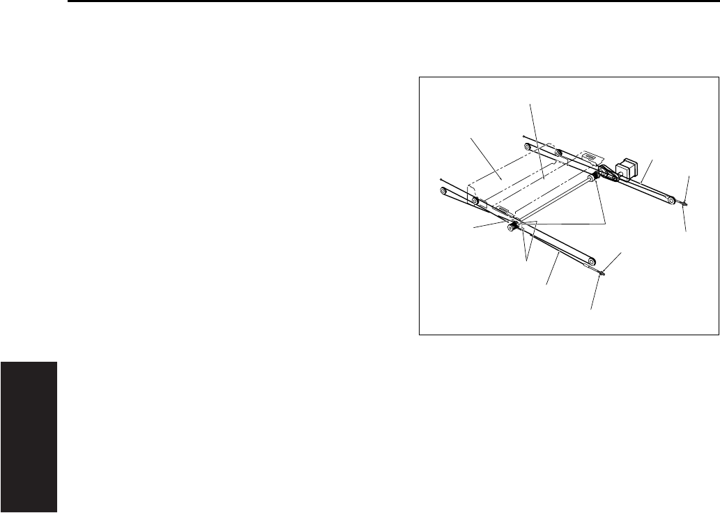
SCANNER SECTION
3-20
III DIS./ASSEMBLY
3.8 Removing the Optics Wire
A. Procedure
1. Remove the RADF.
2. Remove the platen glass.
3. Remove the scanner cover/R.
4. Shift the V mirror unit [1] to the paper exit side.
Through the front, insert the optics unit position-
ing jig so that it is at the V mirror attachment
location. Pass the jig through the V mirror unit
[1] to fasten the it in place.
5. Remove the exposure unit [2].
6. Detach the nuts [5] and washers [6] from the
ends of the optical wires/F [3], /R [4], and
remove the wires/F [3], /R [4].
7. Remove the screws [7] holding the two drive
pulley [8] bearings in place (two screws on each
pulley), and remove the bearings [9].
8. Remove the optical wires/F [3], /R [4] from the
drive pulleys.
[1]
[2]
[3]
[4]
[5]
[5]
[6]
[6]
[7]
[8]
[9]
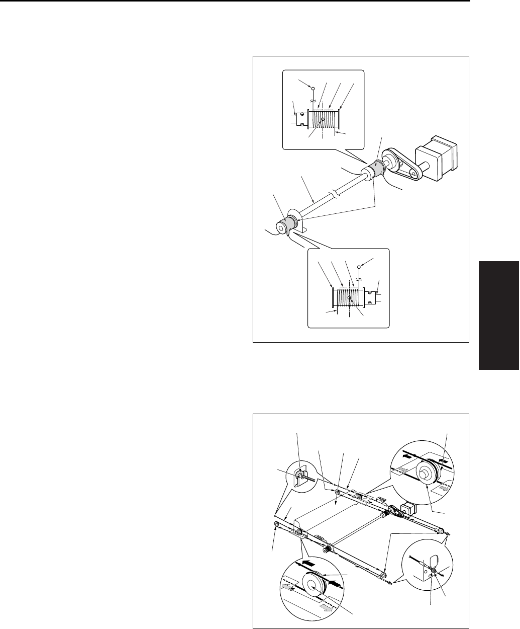
SCANNER SECTION
3-21
III DIS./ASSEMBLY
3.9 Installing the Optics Wire
A. Procedure
1. Loosen the set screw of the drive pulley [1] on
one side so that the drive pulley can rotate
freely against the pulley shaft.
2. Fit the metal ball [3] (midway along each optical
wire [2]) into the mount opening on the drive pul-
ley [1]. Starting from this position, wind 6 times
[4] around the outside and 5 times [5] around
the inside.
• Use the “F” exposure unit mount fitting (the fitting
with the “F” printed on it) at the front, and use the
“R” fitting at the rear.
• The end with the metal ball [7] at the tip winds
around the inside of the pulley shaft [8].
• Wind so that the two ends of the wire come off
the top of the pulley.
3. After winding the wires [1], fasten them in place
(with tape [6], etc.) so that they cannot come off.
Note:
• When winding wire around pulleys, be sure that
the winds are close. Be careful to avoid overlap.
• When changing the wire, be sure to use the
optics unit positioning jig.
4. On the metal ball [1] side, pass the optical wire
[2] so that it passes under the V mirror unit [3],
through the paper exit side pulley [4], and
through the inside pulley [5] on the V mirror unit.
Hook the end of the wire onto the notch [6] on
the frame.
5. On the right side, pass the wire so that it passes
through the right side pulley [7], passes over the
pulley [8] on the outside of the V mirror unit, and
passes under the V mirror unit. Fasten the end
to the right side frame with the nut [9] and
washer [10].
[2]
[3]
[1]
[4]
[5]
[6]
[6]
[7]
[8]
[2]
[3]
[1] [4] [5] [7]
[8]
[3]
[8]
[1]
[2]
[2]
[3]
[4]
[4]
[5]
[5]
[6]
[7]
[8]
[8]
[9]
[10]
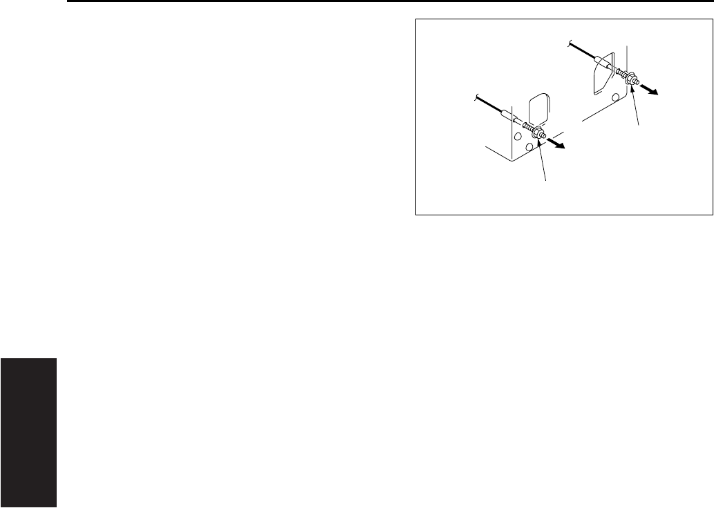
SCANNER SECTION
3-22
III DIS./ASSEMBLY
6. Position the V-mirror unit by using the optics unit
positioning jig.
7. After temporary fastening, use a spring balancer
to apply 1.3 ~ 1.7kg of tension to the front and
rear optical wires in the arrow direction, then
fully tighten the nuts [1].
8. Fasten the set screw of the drive pulley which
has been loosened.
9. Using the optics unit positioning jig to install the
exposure unit.
10. Remove the optics unit positioning jig.
11. Slide the exposure unit two or three times to
make sure that it works correctly.
12. Finish installation by reversing the sequence of
the removal procedure.
[1]
[1]
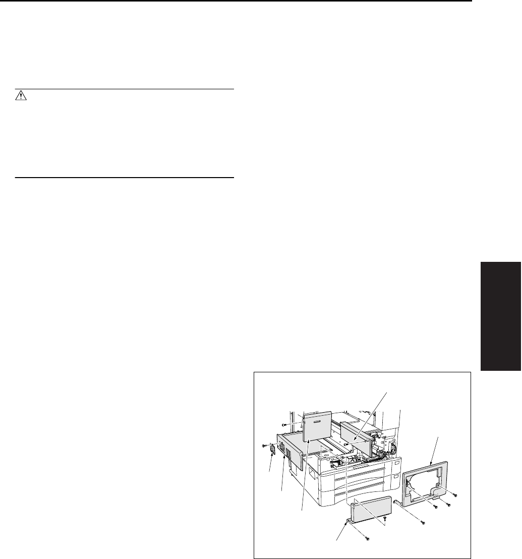
WRITE UNIT
3-23
III DIS./ASSEMBLY
4. WRITE UNIT
4.1 Removing and Reinstalling
the Write Unit
Warning:
• Never supply power while the write unit is
out of its proper installed position.
• Do not open the cover of the write unit while
power is being supplied. Shining of the laser
beam on the eye may cause blindness.
Note:
• When removing the write unit, take care to avoid
touching with the write mirror and the dust proof
glass. (Touching these areas may leave
scratches and smudges.)
• When installing the write unit, confirm that the
PET sheet at the end is seated correctly in the
duct.
• After turning the main power switch OFF, wait at
least two minutes before removing the write unit.
A. Procedure
1. Open the front door and remove the developing
unit and the drum unit.
2. Remove the exit tray.
3. Remove the front door.
4. Remove the main body cover/FR [1], the main
body cover/FL [2], the side cover/R [3], the fil-
ter cover assembly [4], the main body cover/U
[5] and the main body assist cover [6].
[2]
[3]
[5]
[4]
[6]
[1]
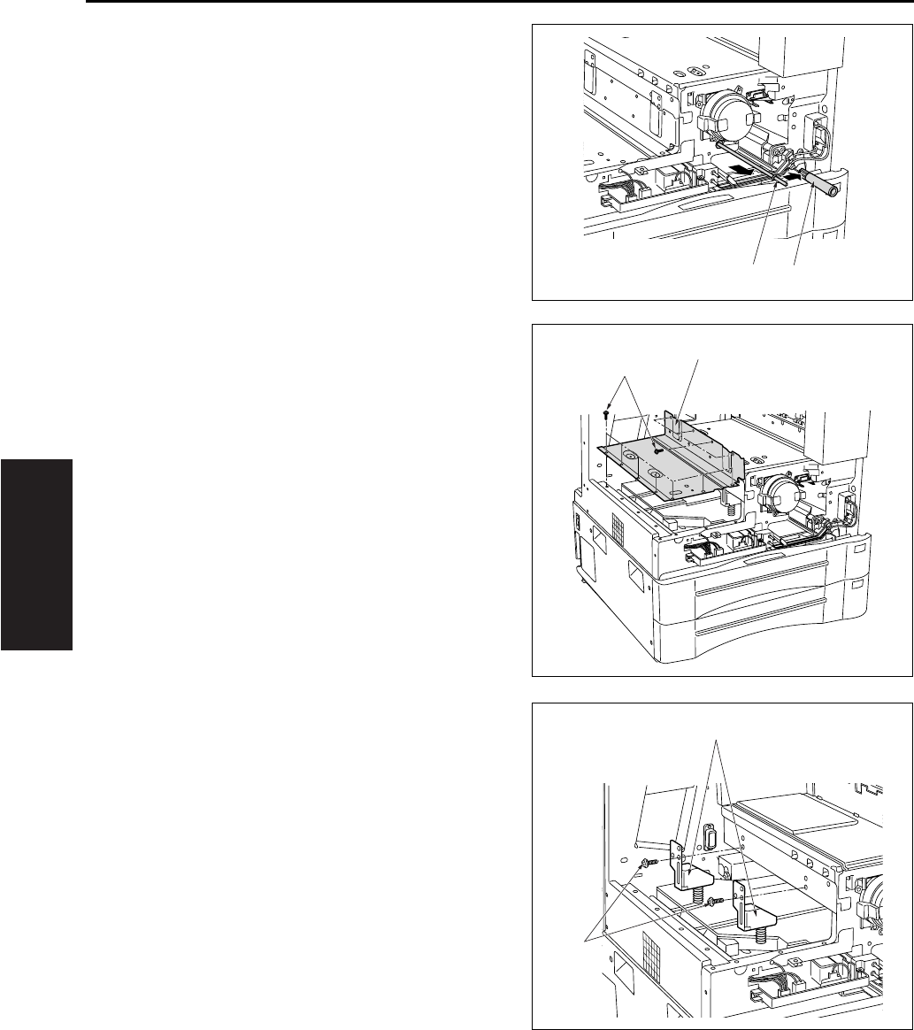
WRITE UNIT
3-24
III DIS./ASSEMBLY
5. Remove the write cleaning knob [2] from the
dust proof glass cleaning rod [1] and then puch
the rod [1] to inside of main body.
6. Remove the 11 screws [1], and remove the write
cover [2].
7. Remove the two write unit mount pieces [2]
(each is held in place by screw [1]).
[1] [2]
[1]
[2]
[1]
[2]
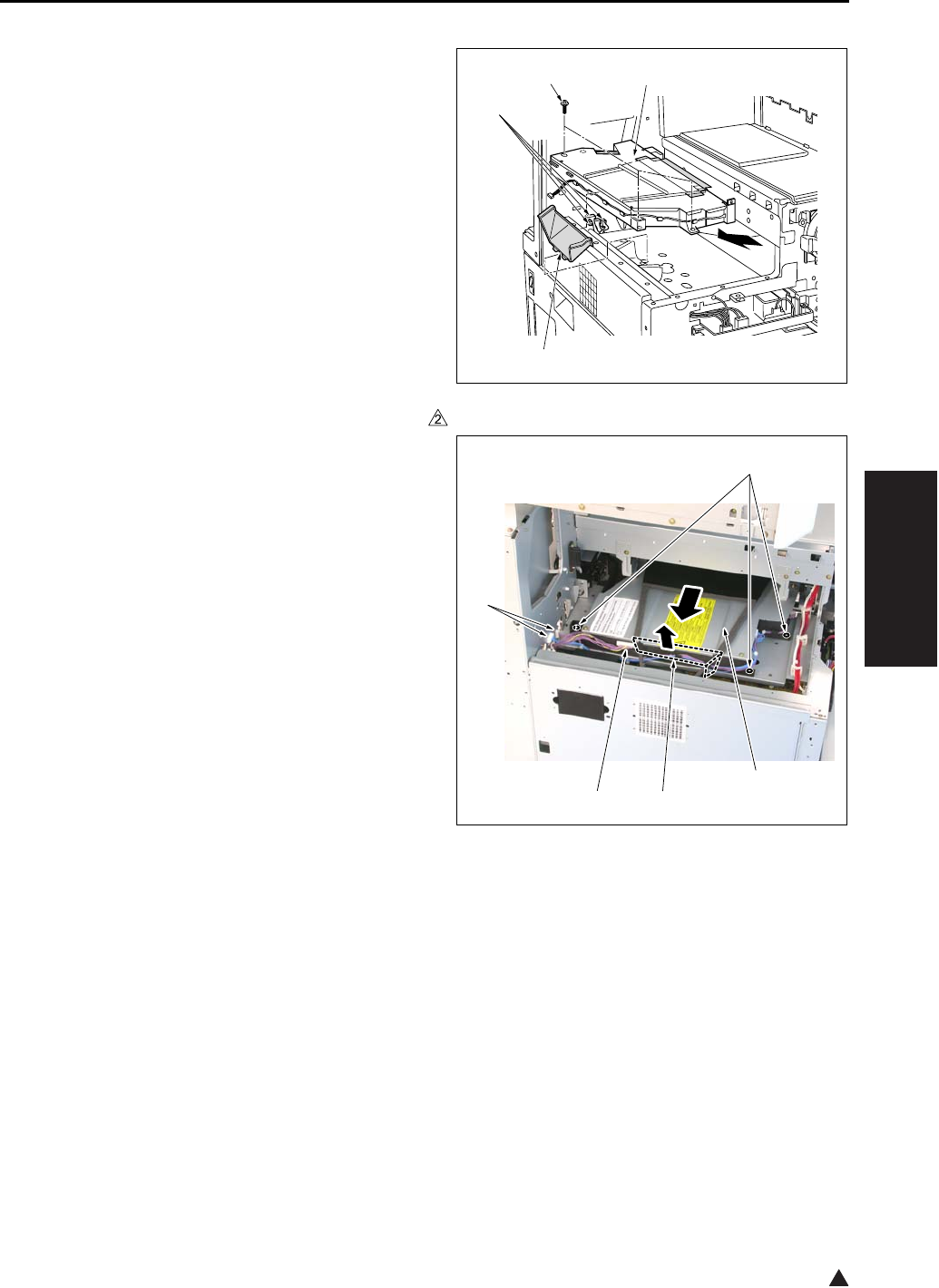
WRITE UNIT
3-25
III DIS./ASSEMBLY
2
8. Disconnect the 3 connectors [1] .
9. Remove the air duct [2].
10. Remove the 3 screws [3] (SEMS II: long
screws), and remove the write unit [4] by pulling
it to the paper exit side.
Note:
• When removing the write unit, take care to avoid
touching with the write mirror and the dust proof
glass.
In the case of the 7145
In the case of the 7235/7228/7222
[1]
[2]
[3] [4]
[1]
[3]
[1] [2]
[4]
7322ma3005
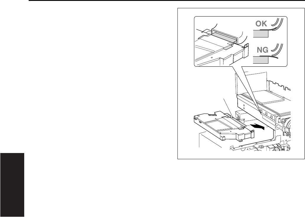
WRITE UNIT
3-26
III DIS./ASSEMBLY
11. Reinstall the above parts following the removal
steps in reverse.
Note:
• Reinstall the write unit while inserting the front
edge of the cooling air guide sheet [1] into the
specified position.
[1]
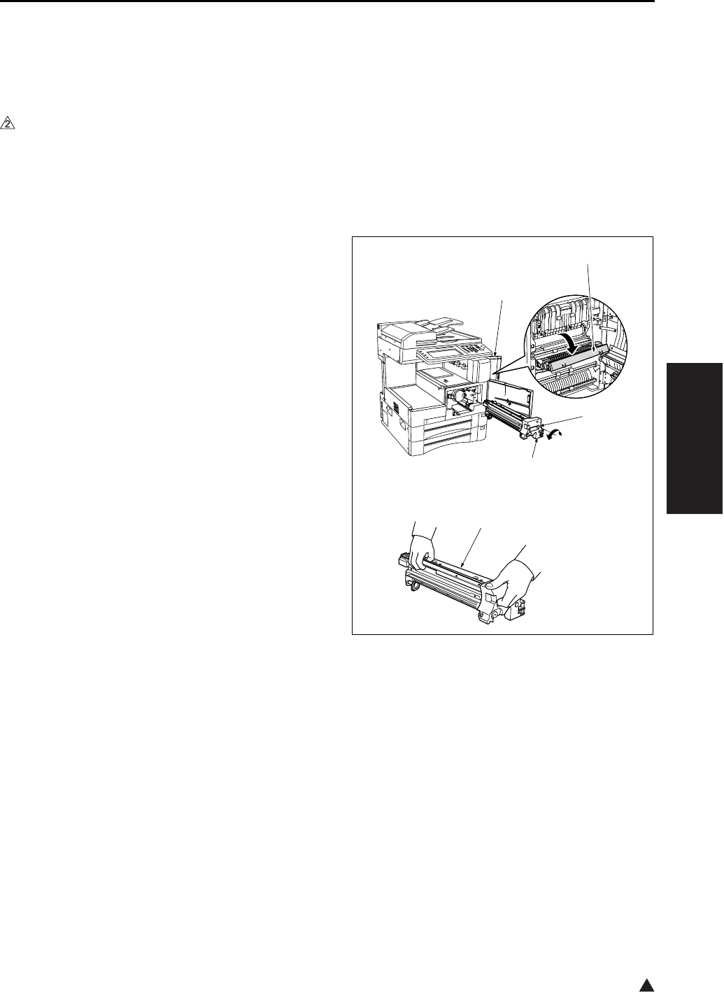
DRUM UNIT
3-27
III DIS./ASSEMBLY
2
5. DRUM UNIT
5.1 Removing and Reinstalling
the Drum Unit
A. Periodically replaced parts/cycle
• Drum unit: Every 720,000 copies (7145)
• Drum unit: Every 600,000 copies (7235/7228/
7222)
B. Procedure
1. Remove the developing unit.
2. Open the ADU door [1], and open the convey-
ance unit [2].
3. Loosen the screw [3], and gently pull the drum
unit [4] out toward you until it stops. Then tilt it
slightly and remove it.
Note:
• When removing the drum unit, be sure to hold it
at both ends to prevent a possible deformation of
the drum unit.
• After removing the drum unit, close the drum
cover and store the unit in a dark place.
• During removal and reinstallation work, never
rotate the drum in the wrong direction (in the
direction opposite to the direction it moves during
normal copying). Rotating the drum in the reverse
direction may cause scratches to the cleaning
blade.
• When removing the drum unit, do not place your
hand on the separation claw unit [5].
4. Reinstall the above parts following the removal
steps in reverse.
[1]
[2]
[3]
[4]
[5]

DRUM UNIT
3-28
III DIS./ASSEMBLY
2
5.2 Removing and Reinstalling
the Charging Corona Unit
A. Procedure
1. Remove the drum unit from the main body.
2. Set the unit so the drum is to the top.
3. Remove the cleaning rod's [1] shaft stopper fit-
ting [2], and pull out the cleaning rod [1].
4. Disconnect the connector [3] from the drum unit.
5. Remove the 2 screws [4] (7235/7228/7222
only).
6. Remove the back side (rear side) of the charg-
ing corona unit [5] in the arrow-marked direction
[6] and remove it by sliding in the arrow-marked
direction [7].
7. Reinstall the above parts following the removal
steps in reverse.
Note:
• Be careful not to bend excessively the charging
corona pressure spring.
5.3 Removing and Reinstalling
the Charge Control Plate
A. Procedure
1. Remove the drum unit from the main body.
2. Remove the charging corona unit. Move the
charging cleaning block to its home position (at
the rear side).
3. Remove the 2 charge control springs [1], and
remove the charge control plate [2].
4. To clean: tap lightly with a cloth soaked in drum
cleaner, then use a blower brush to remove
remaining debris.
5. Reinstall the above parts following the removal
steps in reverse.
Note:
• When reinstalling, be sure to set the charge con-
trol plate so that the spring held end is toward the
front of the charging corona unit.
7322ma3006
2
[1]
[2]
[7]
[6]
[4]
[5]
[3]
[4]
[1]
[2]
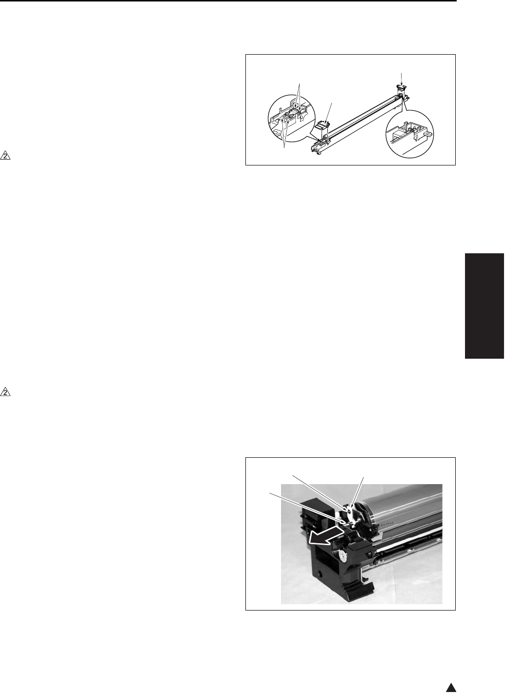
DRUM UNIT
3-29
III DIS./ASSEMBLY
2
5.4 Replacing the Charging Wire
A. Procedure
1. Remove the drum unit from the main body.
2. Remove the charging corona unit. Move the
charging cleaning block to its home position (at
the rear side).
3. Remove the charge control plate.
4. Remove the 2 charging covers (charging cover/F
[1], and charging cover/R [2]).
5. In the case of the 7145
Remove the 2 springs [3], and remove the 2
charging wires [4].
In the case of the 7235/7228/7222
Remove the 2 springs [3], and remove the 1
charging wire [4].
6. To install the replacement wire: first fasten the
rear end of the wire to the unit, then pass the
wire through the charging cleaning block and fix
it in place with the spring. Then complete the
installation by reversing the steps above.
7. Finish installation by reversing the sequence of
the removal procedure.
5.5 Removing and Reinstalling
the Drum
A. Periodically replaced parts/cycle
• Drum: Every 240,000 copies (7145)
• Drum: Every 200,000 copies (7235/7228/7222)
B. Removing procedure
1. Remove the drum unit from the main body.
2. Remove the charging corona unit from the drum
unit.
3. Remove the screw [1] and the fixing material [2],
and pull out the drum shaft [3].
When the drum shaft is hard to pull out, knock
lightly at the rear end of the drum shaft.
[1]
[2]
[3]
[4]
[1] [2]
[3]
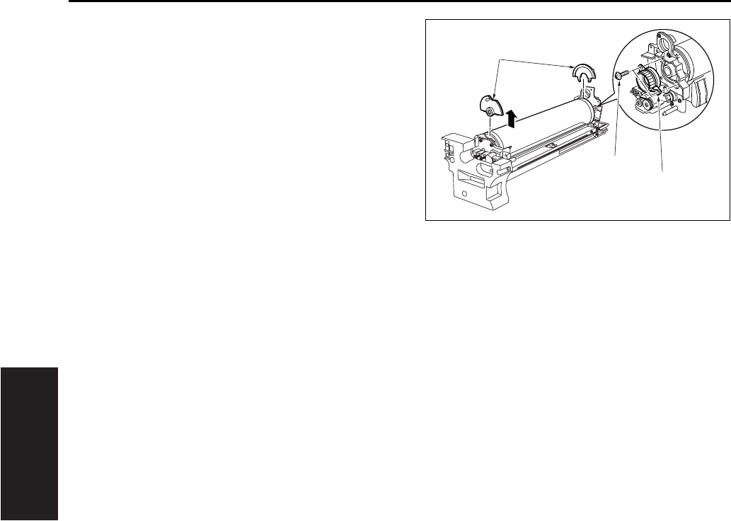
DRUM UNIT
3-30
III DIS./ASSEMBLY
4. Remove the 2 screws [1], and remove the drum
bearing [2].
5. Remove the 2 semicircular seal blocks [3] (one
on each end of the drum).
6. To remove the drum, lift it up and out from the
front side.
Note:
• Take care to avoid scratching the drum's light
sensitive areas and the cleaning blade. Do not
touch these areas with bare hands.
• When removing or installing, never allow the
drum to bump against the plate-metal part of the
cleaning blade.
• If you are going to place the drum in storage, be
sure to place a cover on the drum (to cut off light
to it) and store it in a dark place.
• When removing the drum unit, do not place your
hand on the separation claw unit.
[1]
[2]
[3]
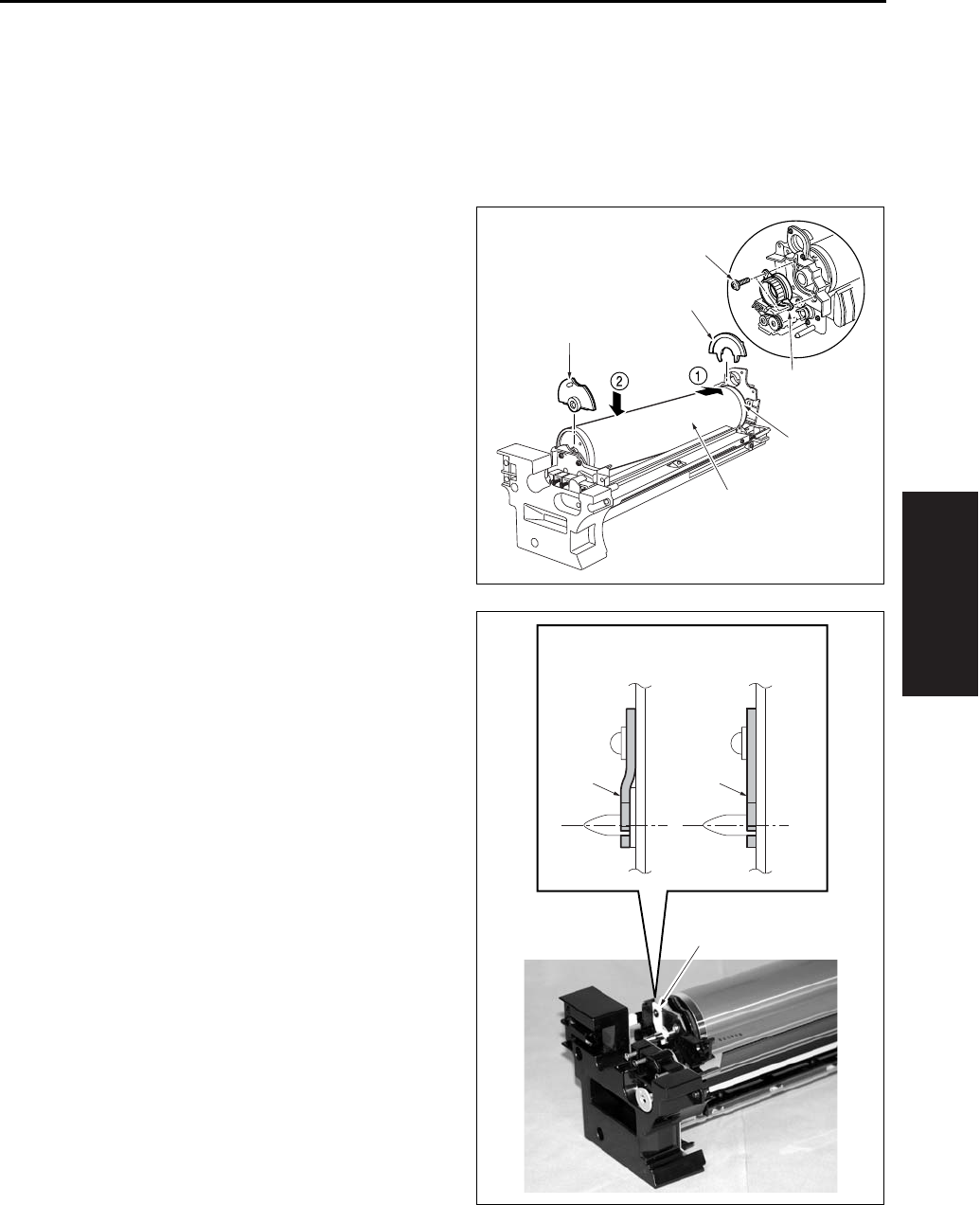
DRUM UNIT
3-31
III DIS./ASSEMBLY
C. Installing procedure
Note:
• Be sure that the toner collection sheet makes
contact with the entire span of the drum, with no
gaps.
1. Coat the entire surface of the drum with setting
powder.
2. Fit the long convex end [2] of the drum [1] into
the rear side of the unit, then set the drum down
into the unit. Reattach the two seal blocks [3]
(one at each end of the drum).
3. Reattach the drum bearing [4]. Fasten it into
place with the 2 set screws [5].
4. Insert the drum shaft and fasten the hold-down
member [4] with a screw. Be sure to attach the
hold-down member securely as shown in the
drawing right.
[5]
[4]
[1]
[2]
[3]
[3]
[4]
[4][4]
OKNG

DRUM UNIT
3-32
III DIS./ASSEMBLY
2
5. Using the jig [1] included on the drum unit cover,
rotate the drum clockwise and confirm that there
are no gaps in the setting powder coat, and that
the toner collection sheet and cleaning blade
are smooth, etc.
6. Finish installation by reversing the sequence of
the removal procedure.
Note:
• Before installing the drum and cleaning blade
(regardless of whether new or used), be sure to
coat these with setting powder. Apply the powder
around the entire drum, and on both sides of the
blade.
• If you have coated setting powder onto the drum:
Before installing the drum unit back into the main
body, use an alcohol-soaked cloth to remove
stray powder from the sensor surface on the
toner control sensor board. This is necessary to
ensure that accurate toner density readings are
obtained.
• Be sure that the drum is oriented correctly before
installing it. The drum should be positioned so
that the convex end of the longer section comes
at the back.
• After installing a new drum, be sure to reset the
drum-related counters in the 36 mode.
[1]
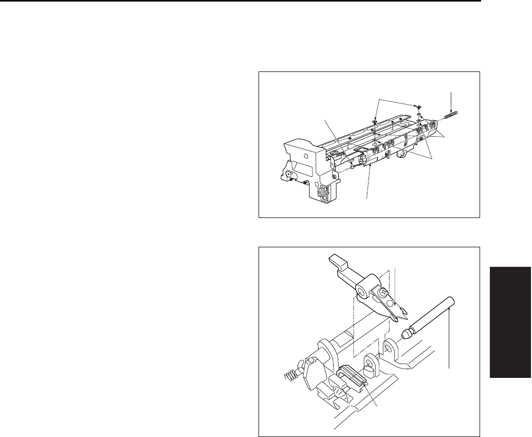
DRUM UNIT
3-33
III DIS./ASSEMBLY
5.6 Removing and Reinstalling
the Separation Claw
A. Procedure
1. Remove the drum unit from the main body.
2. Remove the drum from the drum unit.
3. Disconnect the relay connector [1].
4. Remove the separation rock spring [2].
5. Remove the 2 positioning screws [3], the 2 col-
lars [4] and the 2 spacer [5], and then remove
the separation claw unit [6].
Note:
• While removing or installing the claw, be careful
to avoid damage to the drum.
6. Pull out the separation fulcrum shaft [2] while
pressing down the claw [1] and remove the 2
separation claws [3].
7. Reinstall the above parts following the removal
steps in reverse.
Note:
• When installing the claw, be sure that it is cor-
rectly oriented and positioned.
• Do not touch the cleaning blade or the drum's
light sensitive areas with bare hands.
[1]
[2]
[3]
[4]
[5]
[6]
[1]
[2]
[3]

DRUM UNIT
3-34
III DIS./ASSEMBLY
2
5.7 Removing and Reinstalling
the Transfer and Separation
Corona Unit
A. Periodically replaced parts/cycle
• Transfer corona unit: Every 480,000 copies
(7145)
• Transfer corona unit: Every 400,000 copies
(7235/7228/7222)
B. Procedure
1. Open the ADU door.
2. Pull the conveyance unit [1] toward you to open.
3. Push the rear catch of the transfer/separation
corona unit [2], then remove the unit.
4. Reinstall the above parts following the removal
steps in reverse.
Note:
• When installing the Transfer/Separation corona
unit, be sure that the cleaning material is in home
position at the rear side.
5.8 Replacing the Transfer and
Separation Wires
Note:
• Do not remove the screw that must not be
removed [2] of the paper entrance guide plate [1].
[1]
[2]
[1]
[2]
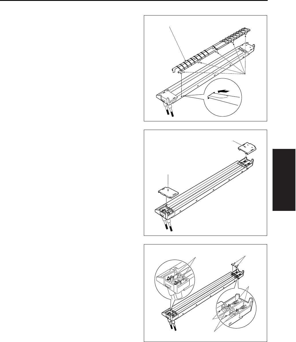
DRUM UNIT
3-35
III DIS./ASSEMBLY
A. Procedure
1. Remove the transfer and separation corona unit
from the main body.
2. Use a tweezers to remove the hook [1] from the
transfer and separation corona unit. Then
remove the plunging prevention plate [2].
3. Remove the spark arrestor plates/F [1], /R [2].
4. Move the cleaning block to home position, and
remove the top covers [1] from the cleaning
block.
5. Remove the spring [2] from each wire, and
remove the wires [3].
Note:
• When removing the wire, be careful that the wire
holding rubber that is in touch with the V-shaped
rack [4] does not get lost.
6. Reinstall the above parts following the removal
steps in reverse.
Note:
• When installing the wire, be sure that the cleaning
block is in home position at the right side. Stretch
the wire so that it fits into the V holders [4].
[1]
[2]
[1]
[2]
[1]
[2]
[3]
[4]
[4]
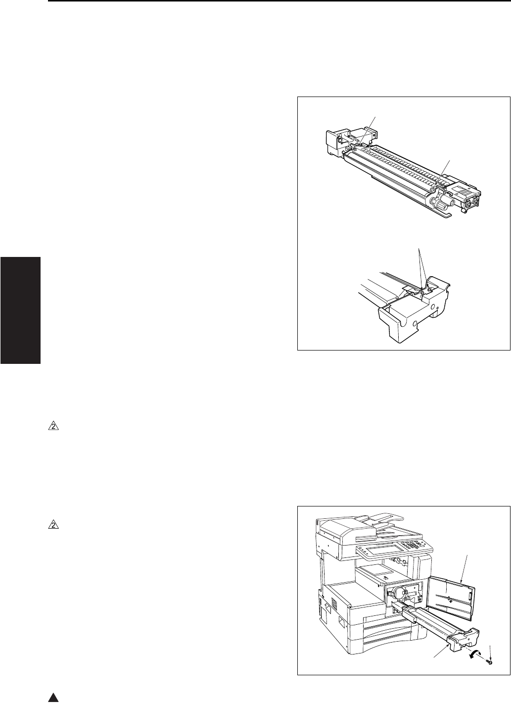
DEVELOPING UNIT
3-36
III DIS./ASSEMBLY
2
6. DEVELOPING UNIT
6.1 Screws That Must Not be
Removed
Note:
• The 4 screws [1] right must not be removed or
adjusted in the field. Please do not interfere with
these screws.
6.2 Removing and Reinstalling
the Developing Unit
A. Periodically replaced parts/cycle
• Developing unit: Every 720,000 copies (7145)
• Developing unit: Every 600,000 copies (7235/
7228/7222)
B. Procedure
1. Open the front door [1].
2. Loosen the screw [2].
3. Pull the developing unit [3] outward to remove.
4. To reinstall: fit the rails on the bottom of the
developing unit onto the grooves on the main
body, and slide the unit into place.
[1]
[1]
[1]
[1]
[2]
[3]
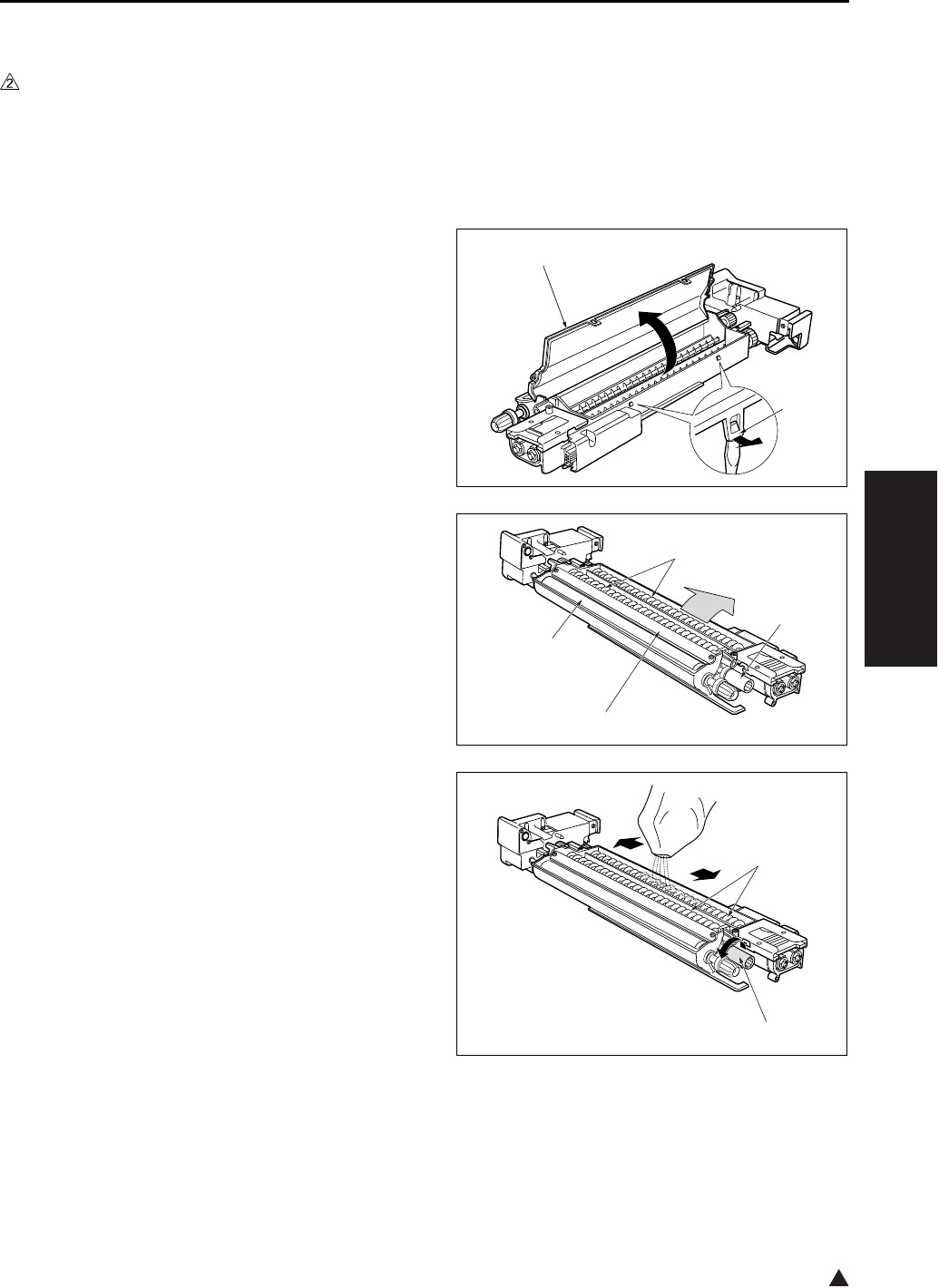
DEVELOPING UNIT
3-37
III DIS./ASSEMBLY
2
6.3 Replacing the Developer
A. Periodically replaced parts/cycle
• Developer: Every 240,000 copies (7145)
• Developer: Every 200,000 copies (7235/7228/
7222)
B. Procedure
1. Remove the developing unit from the main body.
2. Release the hooks [1]. Lift the developing unit
cover [2], and remove it.
3. Tilt the developing unit so that the agitator
screws [1] are toward the bottom, and rotate the
agitator input gear [2] counterclockwise as nec-
essary to discharge all developer from within the
developing unit and from the developing sleeve
[3].
4. Wipe away any toner remaining on the develop-
ing regulator plate [4].
5. Pour new developer evenly over the agitator
screws [1].
Note:
• When carrying out replacement, take care to pre-
vent dirt and debris from entering the system.
6. Rotate the agitator input gear [2] 1 counterclock-
wise so that the developer moves into the inside
of the developing unit.
Note:
• After installing new developer, do not turn the
developer-input gear or agitator input gear in the
clockwise (reverse) direction.
[1]
[2]
[1]
[2]
[4]
[3]
[1]
[2]

DEVELOPING UNIT
3-38
III DIS./ASSEMBLY
7. Repeat steps 5 and 6 as necessary to load all of
the developer.
8. Rotate the developing input gear counterclock-
wise and check the bristle height along the
entire surface of the developing sleeve.
9. Reinstall the developing cover while hooking the
cover onto the projection [1]. Be careful to keep
the cover clear of the scatter prevention sheet
[2].
Note:
• After replacing developer, carry out L detection
adjustment before making copies.
[2]
[1]
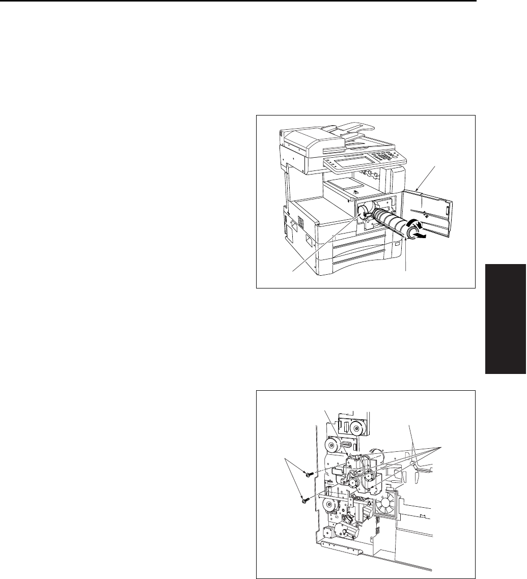
TONER SUPPLY/CLEANING/RECYCLE UNIT
3-39
III DIS./ASSEMBLY
7. TONER SUPPLY/CLEAN-
ING/RECYCLE UNIT
7.1 Removing and Reinstalling
the Toner Bottle
A. Procedure
1. Open the front door [1], and then open the toner
supply cover [2].
2. Pull the toner bottle [3] slightly out, and turn it
clockwise so that the upper part of the cartridge
aligns with the cutout.
3. Withdraw the toner bottle [3].
4. Reinstall the above parts following the removal
steps in reverse.
7.2 Removing and Reinstalling
the Toner Supply Unit
A. Procedure
1. Remove the drum unit and developing unit.
2. Remove the toner bottle.
3. Remove the rear cover.
4. Remove the system control board unit.
• For removal procedure, see “2.1 Removing and
reinstalling the motor units (main, fixing, feed,
developing)”.
5. Remove the drum rotating plate.
6. Remove the 4 connectors [1].
7. Remove the 4 screws [2], and remove the toner
supply unit [3] by pulling it toward you.
8. Reinstall the above parts following the removal
steps in reverse.
[1]
[2] [3]
[1]
[2]
[3]
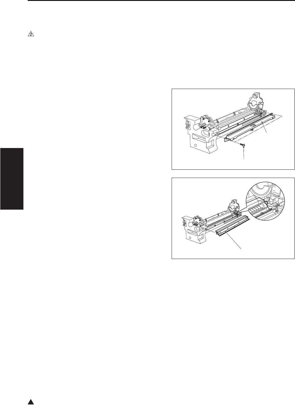
TONER SUPPLY/CLEANING/RECYCLE UNIT
3-40
III DIS./ASSEMBLY
2
7.3 Removing and Reinstalling
the Cleaning Blade
A. Periodically replaced parts/cycle
• Cleaning blade (Cleaning blade assembly):
Every 240,000 copies (7145)
• Cleaning blade (Cleaning blade assembly):
Every 200,000 copies (7235/7228/7222)
B. Procedure
1. Remove the drum unit from the main body.
2. Remove the drum from the drum unit.
3. Remove the 2 screws [1] , and remove the fitting
[2] (suppressor piece) holding the cleaning
blade in place.
4. Remove the cleaning blade [1].
Note:
• Be careful of the cleaning blade edge. Do not
touch the edge with bare hands, and take care to
avoid scratching it.
[1]
[2]
[1]
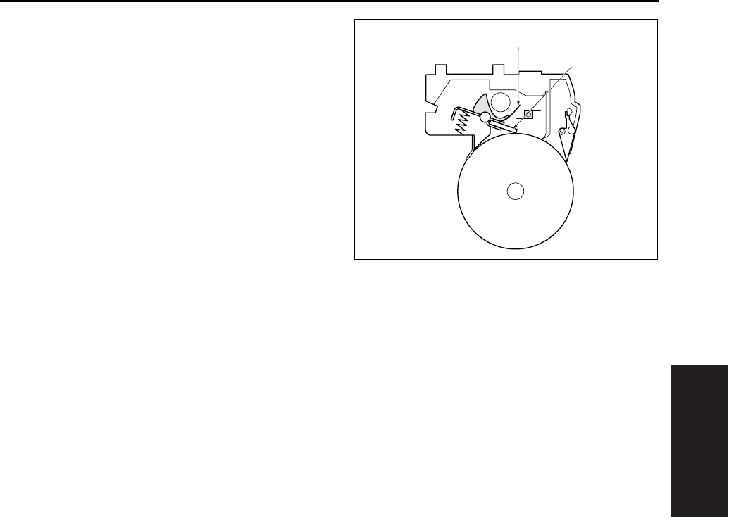
TONER SUPPLY/CLEANING/RECYCLE UNIT
3-41
III DIS./ASSEMBLY
5. Reinstall the above parts following the removal
steps in reverse.
Note:
• When installing the cleaning blade [1], install so
that the unit's transparent sheet [2] is oriented as
shown in the diagram.
• Before installing the drum and cleaning blade
(regardless of whether new or used), be sure to
coat these with setting powder. Apply the powder
around the entire drum, and on both sides of the
blade.
• If you have coated setting powder onto the drum:
Before installing the drum unit rear into the main
body, use an drum cleaner cloth to remove stray
powder from the sensor surface on the TCSB
(Toner control sensor board). This is necessary to
ensure that accurate toner density readings are
obtained.
[1]
[2]
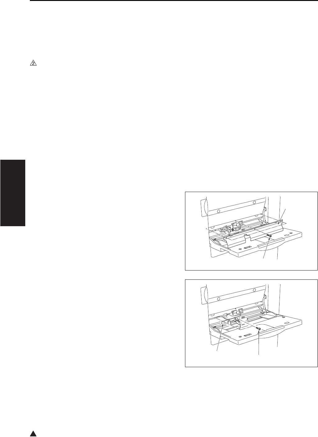
PAPER FEED UNIT
3-42
III DIS./ASSEMBLY
2
8. PAPER FEED UNIT
8.1 Replacing the Paper Feed
Roller and the Feed Roller
(Bypass)
A. Periodically replaced parts/cycle
• Paper feed roller: Every 360,000 copies (Once
for every 100,000 copies for actual durable
count) (7145)
• Paper feed roller: Every 300,000 copies (Once
for every 100,000 copies for actual durable
count) (7235/7228/7222)
• Feed roller: Every 360,000 copies (Once for
every 100,000 copies for actual durable count)
(7145)
• Feed roller: Every 300,000 copies (Once for
every 100,000 copies for actual durable count)
(7235/7228/7222)
B. Procedure
1. Open the bypass tray.
2. Remove the 3 screws [1] and remove the plate
[2].
3. Remove the 2 screws [1], then remove the
bypass sensor.
[1]
[2]
[1]
[2]
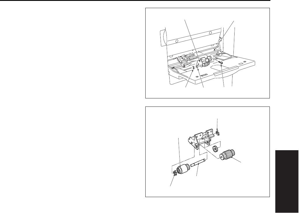
PAPER FEED UNIT
3-43
III DIS./ASSEMBLY
4. Remove the stop ring [1] and the bearing [2].
5. Remove the 2 screws [3]. Then slide the bypass
feed roller unit [4] to the left side and remove it
from the bypass drive shaft [5].
6. Remove the paper feed roller [1].
7. Remove the 2 stop rings [2] .
8. Pull out the bypass conveyance shaft [3], and
remove the feed roller [4].
9. Reinstall the above parts following the removal
steps in reverse.
Note:
• When reinstalling rollers, pay attention to their ori-
entation.
[1] [2] [3]
[5]
[4]
[1]
[2]
[2]
[3]
[4]

PAPER FEED UNIT
3-44
III DIS./ASSEMBLY
2
8.2 Replacing the Double Feed
Prevention Roller
A. Periodically replaced parts/cycle
• Double feed prevention roller: Every 360,000
copies (Once for every 100,000 copies for actual
durable count) (7145)
• Double feed prevention roller: Every 300,000
copies (Once for every 100,000 copies for actual
durable count) (7235/7228/7222)
B. Procedure
1. Carry out the steps 1 through to 5 in “8.1
Replacing the paper feed roller and feed roller
(bypass)”.
2. Remove the 2 screws [1], and remove the by-
pass double feed prevention roller unit [2].
3. Remove the 2 springs [1], the two stop rings [2]
and the E ring [3].
4. Pull out the shaft [4] to the side where there is
no E ring provided, and remove the bypass
reverse roller [5] and the roller [6].
5. Reinstall the above parts following the removal
steps in reverse.
Note:
• When reinstalling double feed prevention roller
[5], pay attention to their orientation.
[1]
[2]
7145ma3006
2
[1]
[1]
[2]
[3]
[4]
[5]
[6]
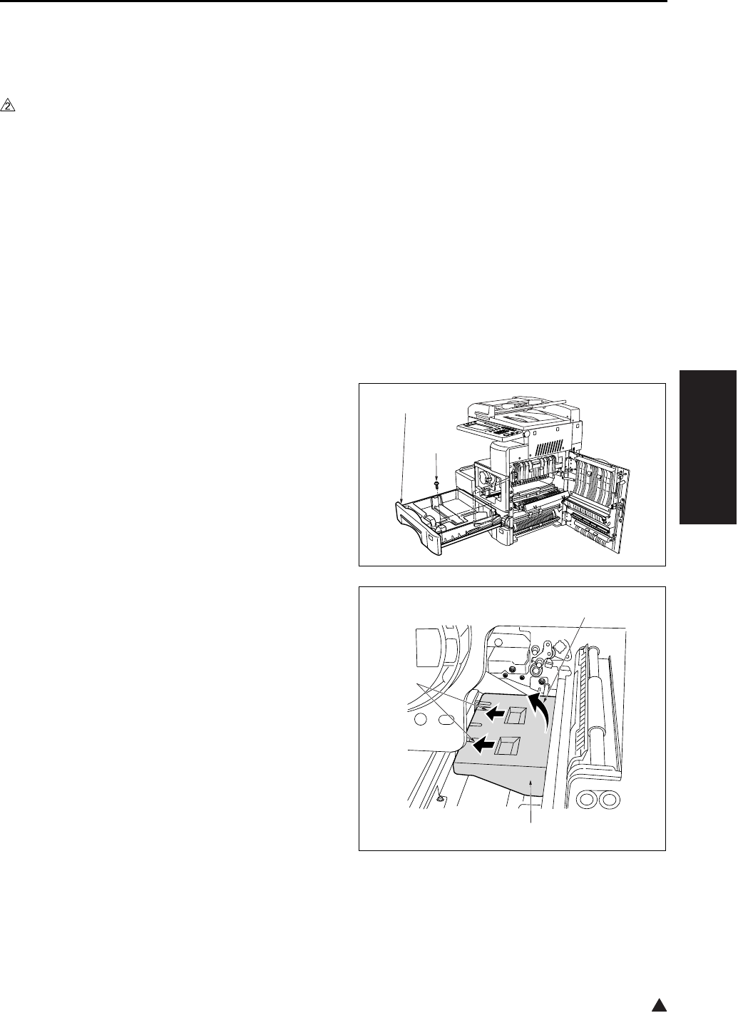
PAPER FEED UNIT
3-45
III DIS./ASSEMBLY
2
8.3 Replacing the Paper Feed
Rubber and the Feed Rubber
(Tray 1)
A. Periodically replaced parts/cycle
• Paper feed rubber: Every 480,000 copies (Once
for every 200,000 copies for actual durable
count) (7145)
• Paper feed rubber: Every 400,000 copies (Once
for every 200,000 copies for actual durable
count) (7235/7228/7222)
• Feed rubber: Every 480,000 copies (Once for
every 200,000 copies for actual durable count)
(7145)
• Feed rubber: Every 400,000 copies (Once for
every 200,000 copies for actual durable count)
(7235/7228/7222)
B. Procedure
1. Open the ADU door, and then open the convey-
ance unit.
2. Remove the developing unit, the drum unit and
the fixing unit.
3. Slide the upper tray 1 [1] out. Remove the 2
screws [2] holding the tray in place, and take the
tray 1 [1] off.
4. Remove the paper feed roller cover [3] in the
direction of arrow [2] while pushing it in the
direction of arrow [1].
[1]
[2]
[1]
[2]
[3]
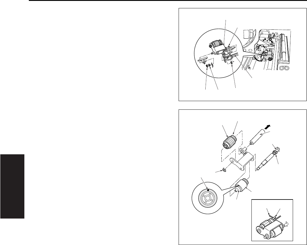
PAPER FEED UNIT
3-46
III DIS./ASSEMBLY
5. Remove the 2 stop rings [1] and the bearing [2].
6. Remove the feed shaft [5] from the rocking shaft
[4] while raising the shaft on the left side of the
paper feed roller unit [3], and remove the paper
feed roller unit [3].
7. Remove the collar [1] and pull out the feed shaft
[2].
8. Remove the feed rubber [4] from the feed roller
[3].
9. Remove the stop ring [5] and pull out the paper
feed shaft [6].
10. Remove the paper feed rubber [8] from the
paper feed roller [7].
11. Reinstall the above parts following the removal
steps in reverse.
Note:
• Be sure to install the feed rubber [4] so that the
paint mark [9] is turned in the direction as shown
in the illustration.
• Install the paper feed roller unit so that the hook
of the paper feed roller unit comes above the
paper feed roller unit release arm.
[1] [1]
[2]
[4]
[5]
[3]
[11] [10]
[1]
[2]
[3]
[4]
[5]
[6]
[7]
[8]
[9]
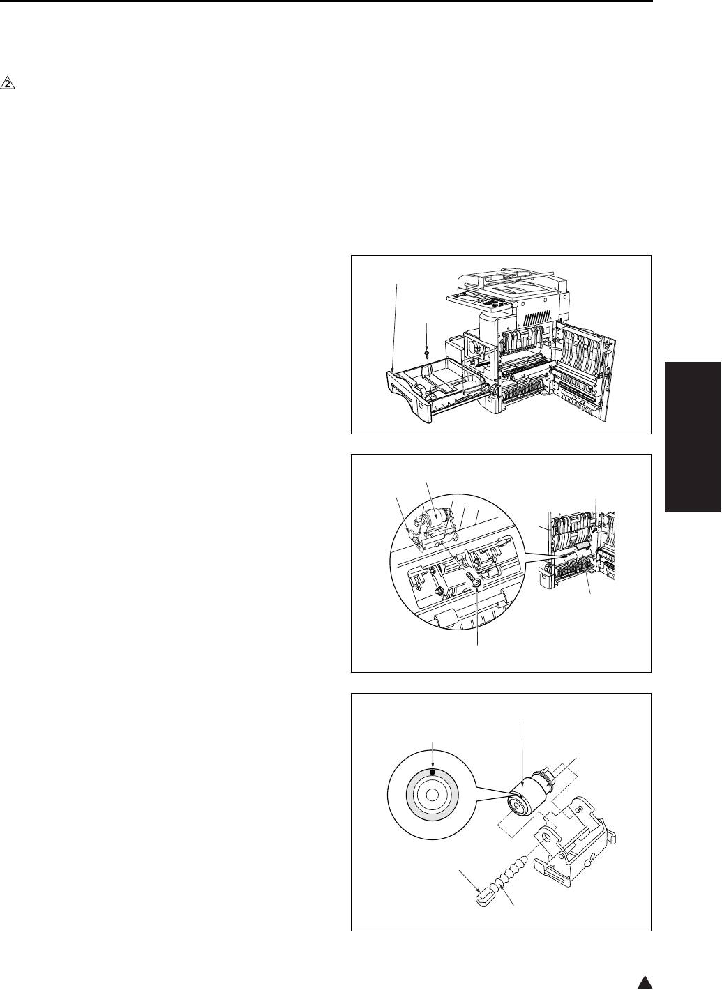
PAPER FEED UNIT
3-47
III DIS./ASSEMBLY
2
8.4 Replacing the Double Feed
Prevention Rubber (Tray 1)
A. Periodically replaced parts/cycle
• Double feed prevention rubber: Every 480,000
copies (Once for every 200,000 copies for actual
durable count) (7145)
• Double feed prevention rubber: Every 400,000
copies (Once for every 200,000 copies for actual
durable count) (7235/7228/7222)
B. Procedure
1. Open the ADU door.
2. Slide the tray 1 [1] out. Remove the 2 screws [2]
holding the tray in place, and take the tray 1 [1]
off.
3. Remove the screw [1], and remove the plate [2].
4. Remove the screw [3].
5. With the claws [4] on both ends sandwiched
from the inside of the main body, remove the
double feed prevention roller unit [5].
6. Pull out the lever click shaft [1] while pushing
the lever section [2] of the lever click shaft [1].
7. Remove the double feed prevention rubber [4]
from the double feed prevention roller [3].
[1]
[2]
[1]
[2]
[3]
[4]
[5]
[1]
[2]
[3]
[4]
[5]
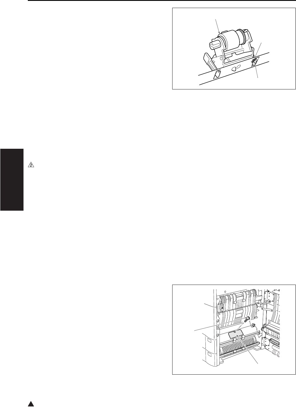
PAPER FEED UNIT
3-48
III DIS./ASSEMBLY
2
8. Reinstall the above parts following the removal
steps in reverse.
Note:
• Be sure to install the double feed prevention rub-
ber so that the paint mark [5] above is turned in
the direction as shown in the illustration.
• When installing the double feed prevention roller
unit [1] to the main body, be sure to align the
upper section of the claw [2] with the center (the
longest scale) of the marking [3] stamped on the
main body frame for leveling.
8.5 Replacing the Paper Feed
Rubber and the Feed Rubber
(Tray 2)
A. Periodically replaced parts/cycle
• Paper feed rubber: Every 480,000 copies (Once
for every 200,000 copies for actual durable
count) (7145)
• Paper feed rubber: Every 400,000 copies (Once
for every 200,000 copies for actual durable
count) (7235/7228/7222)
• Feed rubber: Every 480,000 copies (Once for
every 200,000 copies for actual durable count)
(7145)
• Feed rubber: Every 400,000 copies (Once for
every 200,000 copies for actual durable count)
(7235/7228/7222)
B. Procedure
1. Open the ADU door.
2. Remove the screw [1], and remove the plate [2].
[1]
[2]
[3]
[1]
[2]
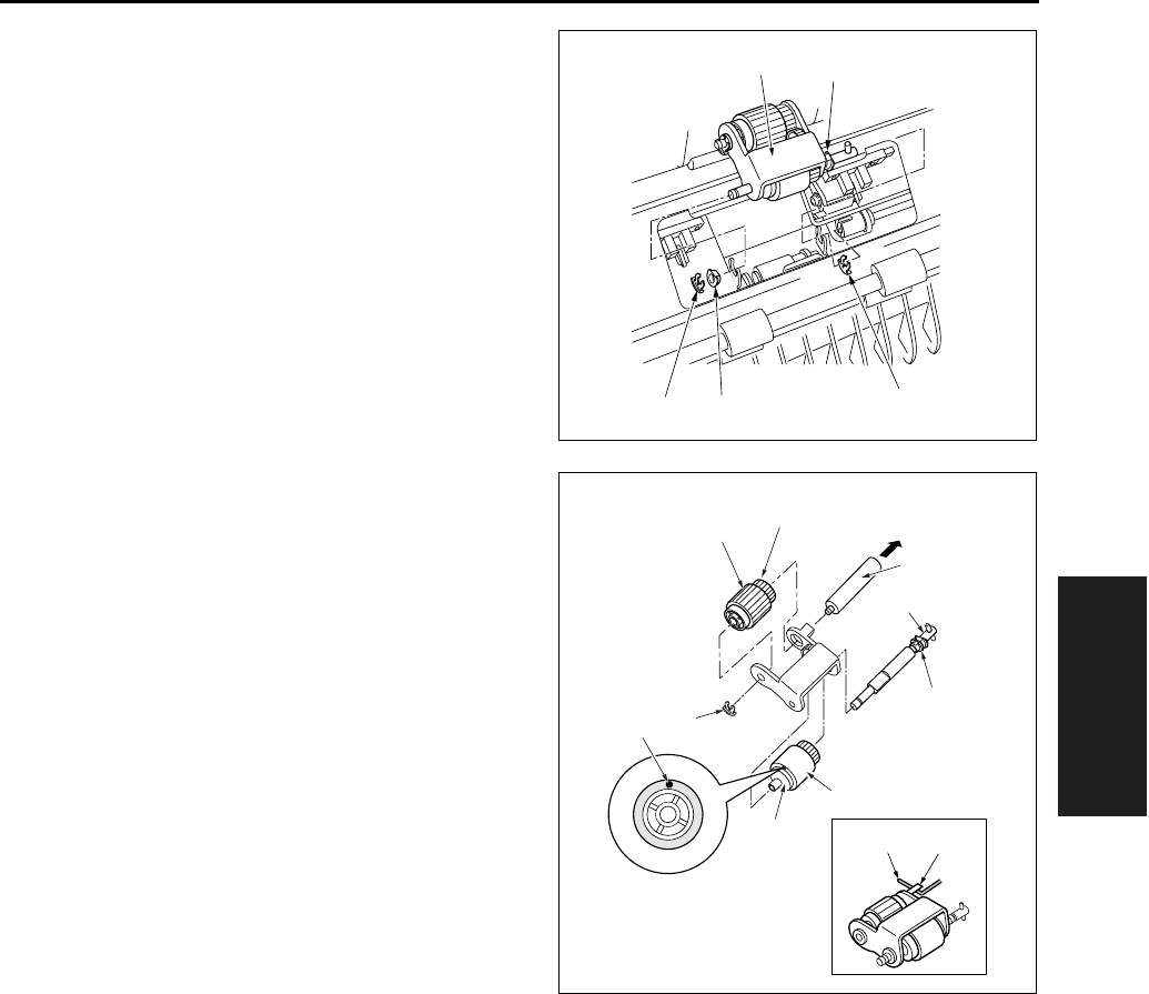
PAPER FEED UNIT
3-49
III DIS./ASSEMBLY
3. Remove the 2 stop rings [1] and the bearing [2]
on this side, and remove the paper feed roller
unit [4] by sliding the bearing [3] on the rear side
to the rear.
4. Remove the collar [1] and pull out the feed shaft
[2].
5. Remove the feed rubber [4] from the feed roller
[3].
6. Remove the stop ring [5] and pull out the paper
feed shaft [6].
7. Remove the paper feed rubber [8] from the
paper feed roller [7].
8. Reinstall the above parts following the removal
steps in reverse.
Note:
• Be sure to install the feed rubber [4] so that the
paint mark [9] is turned in the direction as shown
in the illustration.
• Install the paper feed roller unit so that the hook
of the paper feed roller unit comes above the
paper feed roller unit release arm.
[1] [1]
[2]
[3]
[4]
[11] [10]
[1]
[2]
[3]
[4]
[5]
[6]
[7]
[8]
[9]
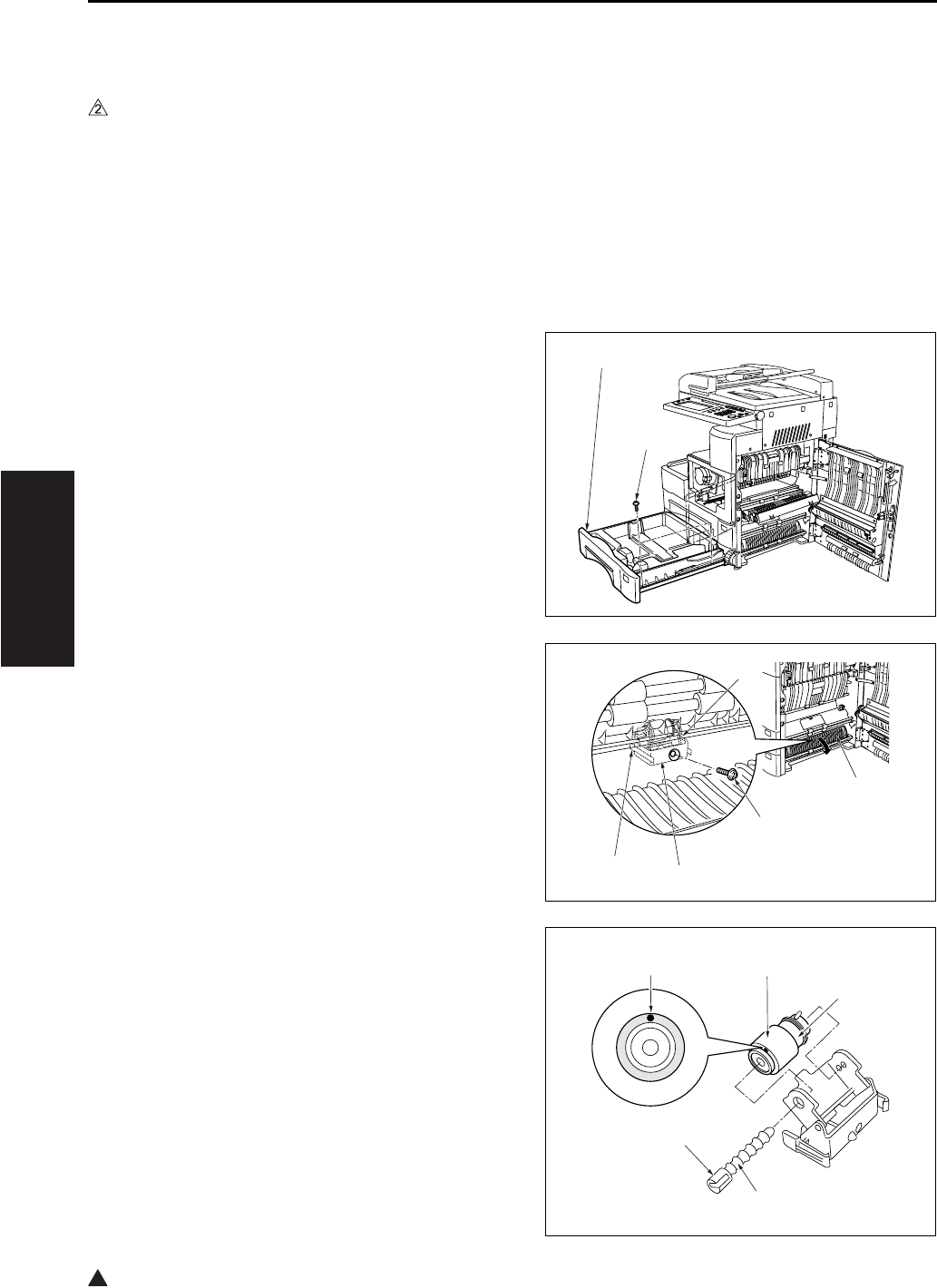
PAPER FEED UNIT
3-50
III DIS./ASSEMBLY
2
8.6 Replacing the Double Feed
Prevention Rubber (Tray 2)
A. Periodically replaced parts/cycle
• Double feed prevention rubber: Every 480,000
copies (Once for every 200,000 copies for actual
durable count) (7145)
• Double feed prevention rubber: Every 400,000
copies (Once for every 200,000 copies for actual
durable count) (7235/7228/7222)
B. Procedure
1. Open the ADU door.
2. Slide the tray 2 [1] out. Remove the 2 screws [2]
holding the tray in place, and take the tray 2 [1]
off.
3. Open the guide plate [1], and remove the set
screw [2].
4. With the claws [3] on both ends sandwiched
from the inside of the main body, remove the
double feed prevention roller unit [4].
5. While pressing on the lever [2] on the lever click
shaft [1], pull out the lever click shaft [1].
6. Remove the double feed prevention rubber [4]
from the roller [3].
[1]
[2]
[1]
[2]
[3]
[3]
[4]
[1]
[2]
[3]
[4]
[5]

PAPER FEED UNIT
3-51
III DIS./ASSEMBLY
7. Reinstall the above parts following the removal
steps in reverse.
Note:
• Be sure to install the double feed prevention rub-
ber so that the paint mark [5] above is turned in
the direction as shown in the illustration.
• When installing the double feed prevention roller
unit [1] to the main body, be sure to align the
upper section of the claw [2] with the center (the
longest scale) of the marking [3] stamped on the
main body frame for leveling.
8.7 Cleaning the Paper Dust
Removing Brush
1. Open the ADU door, and then open the convey-
ance unit.
2. Remove the developing unit and the drum unit.
3. Release the catch of the claw [3] while lifting up
slightly the lower section on this side [2] of the
paper dust removing brush [1], and remove the
paper dust removing brush [1] in the arrow-
marked direction.
Note:
• Do not bend the metal plate of the paper dust
removing brush [1].
4. Clean the PET sheet [1] and the plastic part [2]
using a cleaning pad and a blower brush.
A. Installation procedure
1. Insert the paper dust removing brush [1] from
the rear side [2], and confirm that the hole [3] in
the brush [1] is engaged with the claw [4].
2. Finish installation by reversing the sequence of
the removal procedure.
[1]
[2]
[3]
[2]
[3]
[1]
[1]
[2]
[1]
[2] [3]
[4]
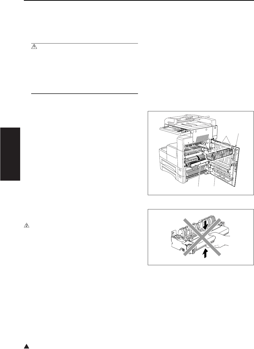
FIXING UNIT
3-52
III DIS./ASSEMBLY
2
9. FIXING UNIT
9.1 Removing and Reinstalling
the Fixing Unit
Caution:
• The fixing unit remains extremely hot imme-
diately after power is switched OFF. To avoid
injury from burns, do not begin work until the
fixing unit has cooled down sufficiently.
• When installing the fixing unit, be sure to
firmly tighten the unit's 2 set screws.
A. Procedure
1. Open the ADU door [1] and the conveyance unit
[2], and loosen the 2 screws [4] holding the fix-
ing unit [3] in place.
2. Pull the fixing unit out toward you and remove it.
Note:
• Do not touch the areas shown in the diagram right
when attaching or removing the fixing unit.
• Observe care, as force applied to the fixing claw
and paper exit guide may result in the rollers
being scratched.
3. Reinstall the above parts following the removal
steps in reverse.
[1]
[2] [3]
[4]
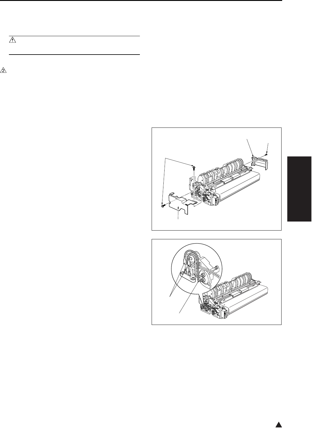
FIXING UNIT
3-53
III DIS./ASSEMBLY
2
9.2 Replacing the Fixing Heater
Lamp/1 and Lamp/2
Caution:
• Do not touch the lamp area with bare hands.
A. Periodically replaced parts/cycle
• Fixing heater lamp/1: Every 480,000 copies
(7145 only)
• Fixing heater lamp/2: Every 480,000 copies
(7145 only)
B. Procedure
1. Remove the fixing unit from the main body.
2. Remove the screws [1], and remove the 2 cov-
ers/F [2], /R [3].
3. Detach the faston terminal [1] at the rear of each
lamp.
Note:
• The marking “B” is stamped on the hole of the
lamp support piece for the L3 (Fixing heater lamp
/3) [2].
[1]
[1]
[2]
[3]
[1]
[2]
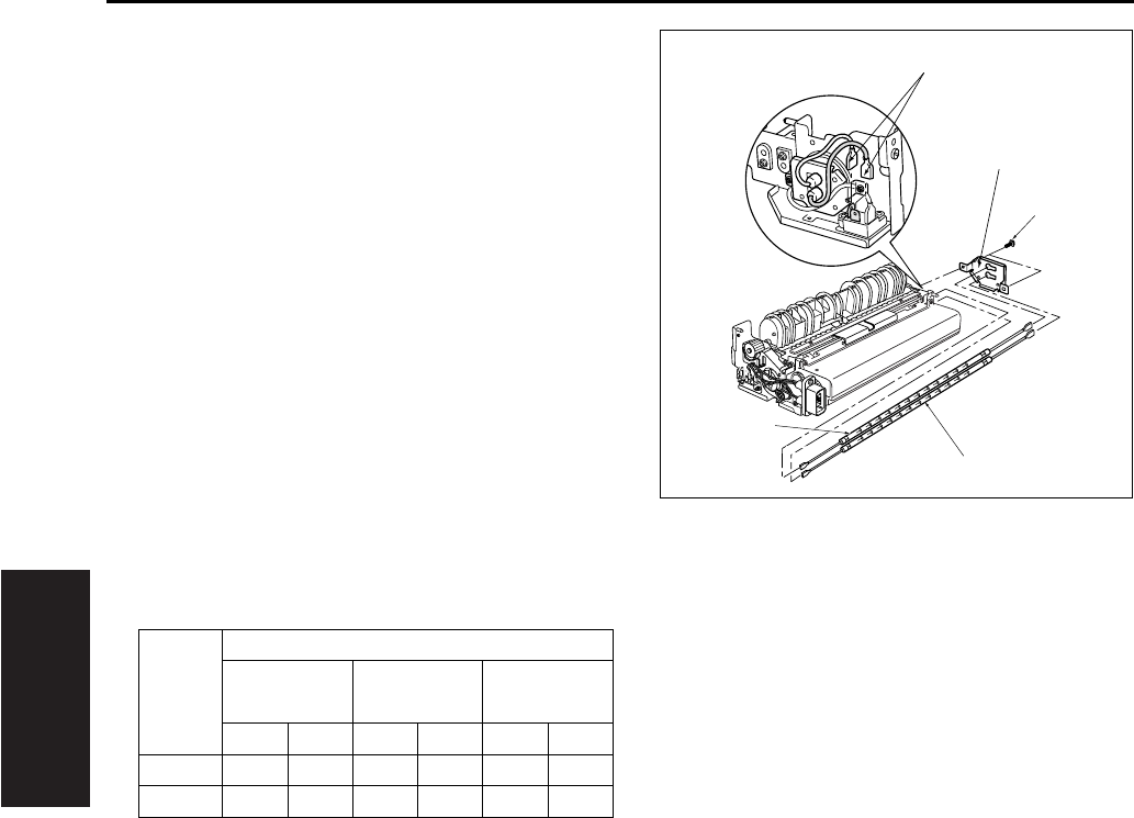
FIXING UNIT
3-54
III DIS./ASSEMBLY
4. Detach the faston terminal [1] at the front of
each lamp.
5. Remove the 2 screws [2], and remove the lamp
support piece/F [3].
6. Keeping all cord faston terminal wiring straight,
pull each fixing heater lamp/1 [4], /2 [5] toward
you to remove.
7. Reinstall the above parts following the removal
steps in reverse.
Note:
• When installing, be sure that manufacturer's mark
is mounted on the front side.
• Do not allow the heater lamps to make contact
with the inside of the roller.
• Install so that the main lamp is at the top, and the
sub lamp is at the bottom.
Heater cords are color-coded as follows.
• When installing the faston terminal on the drive
gear side, be sure that the installation position is
correct.
Lamp
Color Positions
JAPAN U.S.A. EUROPE
OTHERS
Front Rear Front Rear Front Rear
Main White White Red Red Blue Blue
Sub White Black Red Black Blue Black
[1]
[2]
[3]
[4]
[5]
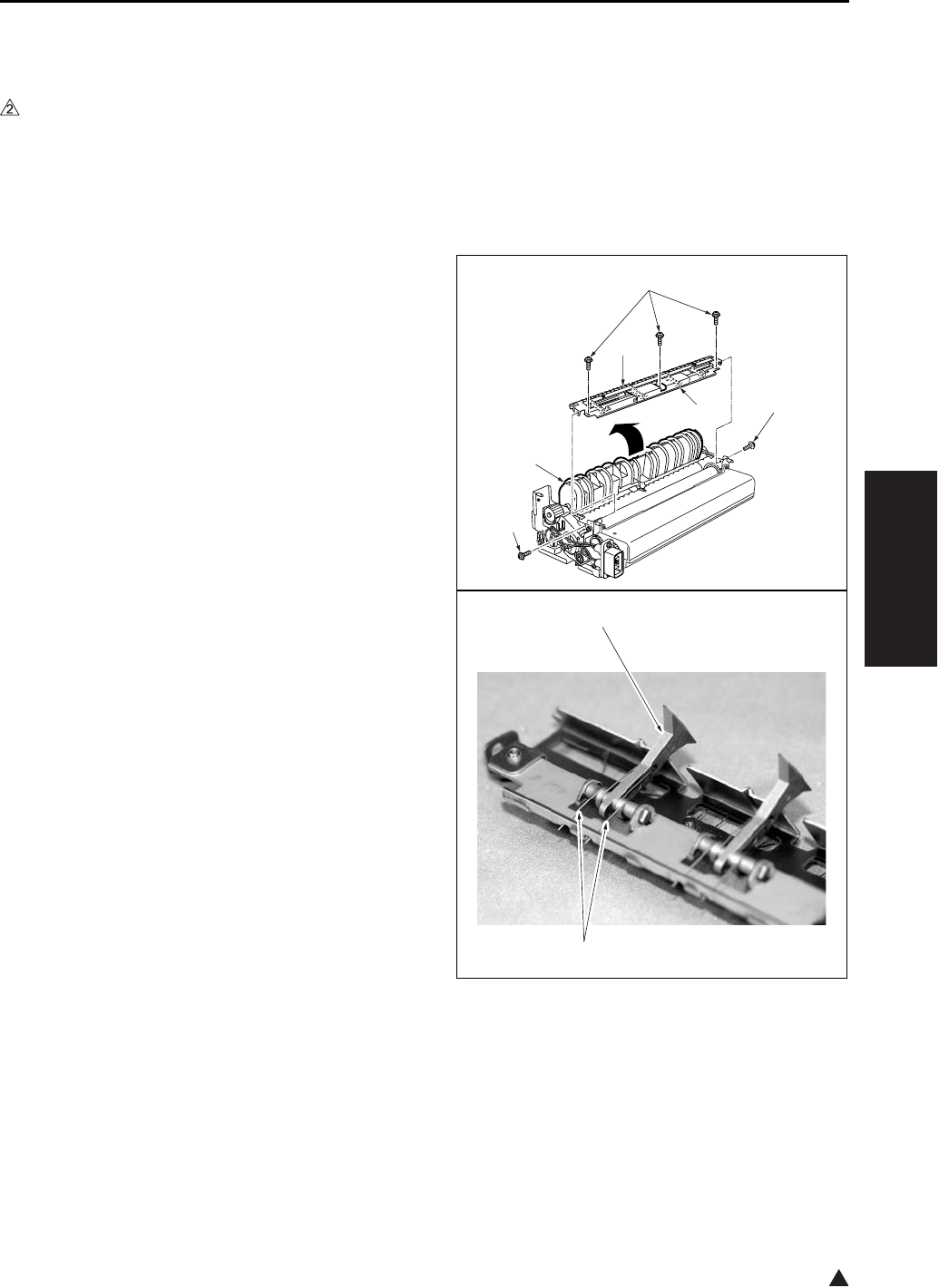
FIXING UNIT
3-55
III DIS./ASSEMBLY
2
9.3 Removing and Reinstalling
the Fixing Claw
A. Periodically replaced parts/cycle
• Fixing claw: Every 240,000 copies (7145)
• Fixing claw: Every 200,000 copies (7235/7228/
7222)
B. Procedure
1. Remove the fixing unit from the main body.
2. Remove the 2 covers/F, /R.
3. Open the fixing guide [1].
4. Remove the 2 set screws [2], and remove the
fixing paper exit board/U [3].
5. Remove the 3 screws [4] from the fixing paper
exit board/U, and remove the fixing claw unit [5].
6. Unhook the spring [1] of the fixing claw unit, and
remove the fixing claw [2].
7. Reinstall the above parts following the removal
steps in reverse.
Note:
• When installing the fixing claw, be sure that it is
oriented correctly.
• Be sure that the claw is securely attached to the
claw spring.
• When installing the fixing paper exit board/U to
the fixing unit, be careful not to damage the fixing
roller with the fixing claw.
[1]
[2]
[2]
[3]
[5]
[4]
[1]
[2]
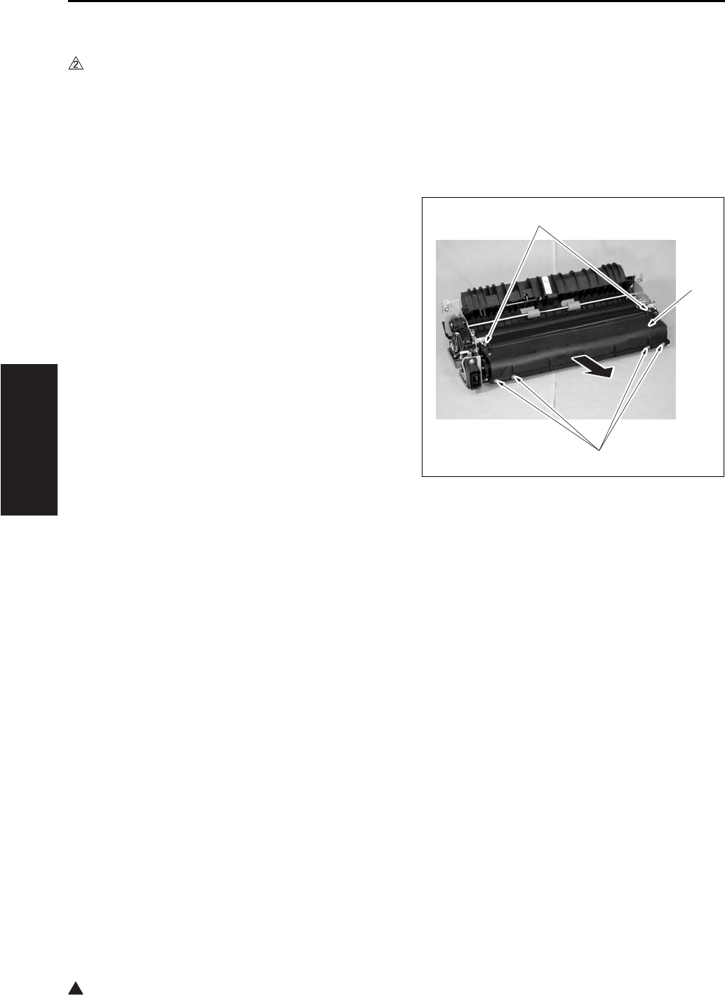
FIXING UNIT
3-56
III DIS./ASSEMBLY
2
9.4 Replacing the Fixing Web
A. Periodically replaced parts/cycle
• Fixing web (Fixing cleaner assembly) : Every
240,000 copies (7145)
• Fixing web (Fixing cleaner assembly) : Every
200,000 copies (7235/7228/7222)
B. Procedure
1. Remove the fixing unit from the main body.
2. Remove the front cover and the rear cover of
the fixing unit.
3. Remove the fixing paper exit board/U.
4. Remove the 6 screws [1] and remove the fixing
web [2].
[1]
[1]
[2]
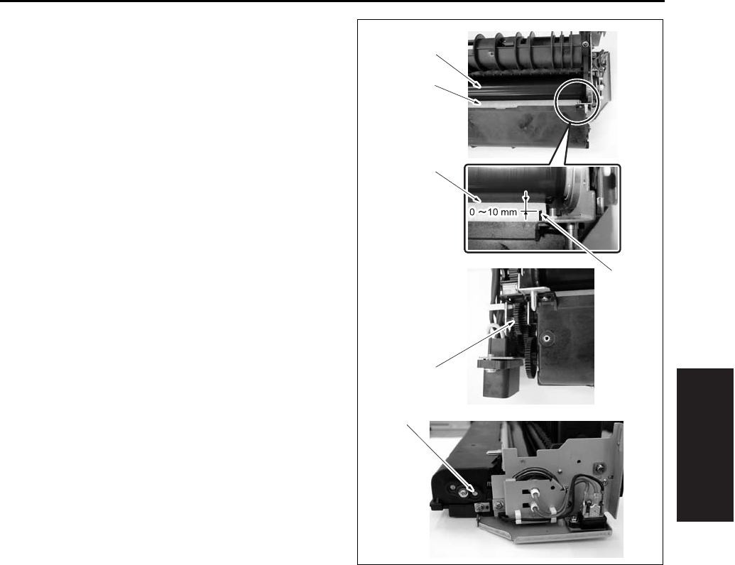
FIXING UNIT
3-57
III DIS./ASSEMBLY
5. Reinstall the above parts following the removal
steps in reverse.
Note:
• When replacing the fixing web, be sure to rotate
the web drive gear [5] to wind up the edge in blue
line [1] of the fixing web until it comes between 0
and 10mm from the nip section [4] of the fixing
heating roller [2] and the fixing cleaning roller [3].
On this occasion, be sure to check the web wind-
ing shaft [6] if it is also rotating.
[5]
[1]
[2]
[3]
[4]
[6]
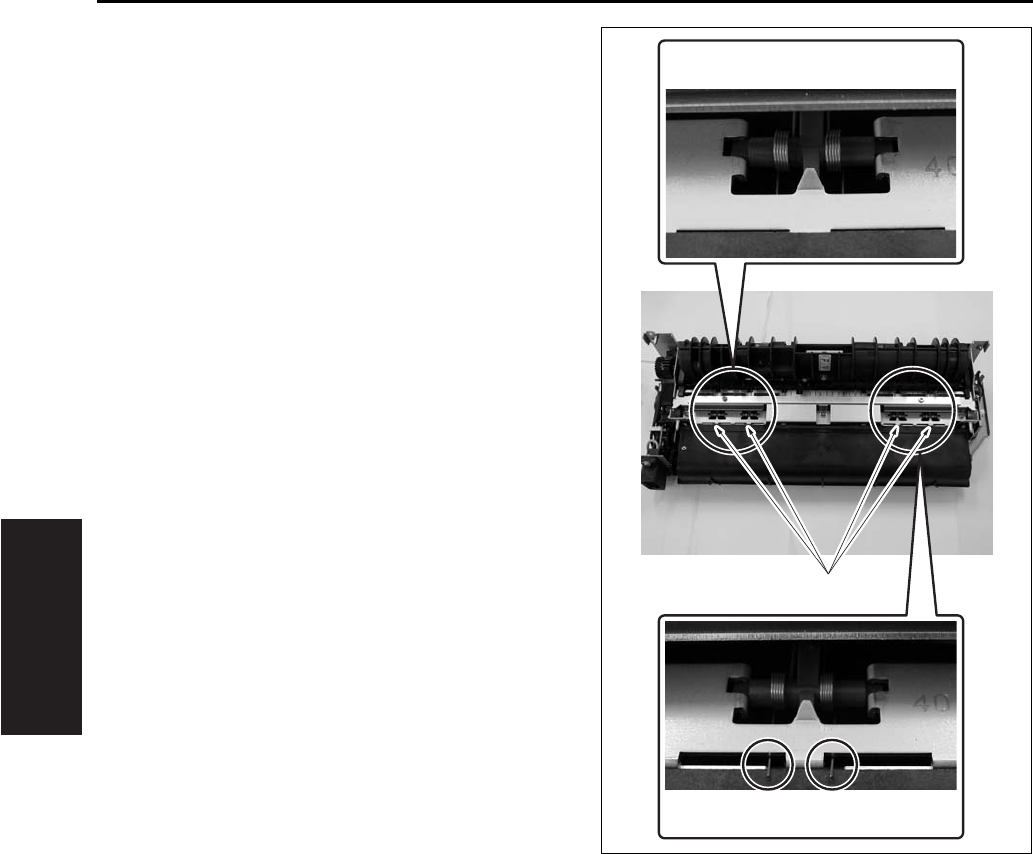
FIXING UNIT
3-58
III DIS./ASSEMBLY
• When installing the fixing claw unit, be careful
that the edge of the fixing claw pressing spring [1]
does not run on the web case.
[1]
OK
NG

FIXING UNIT
3-59
III DIS./ASSEMBLY
2
9.5 Removing/Reinstalling the
Fixing Heat Roller, Fixing
Pressure Roller, Heat Insulat-
ing Sleeve/A, /B, Fixing
Idling gear /B, Fixing Bearing
/U, /L, Heater Lamp/1, /2
A. Periodically replaced parts/cycle
• Fixing heat roller: Every 120,000 copies (7145)
• Fixing heat roller: Every 200,000 copies (7235/
7228/7222)
• Fixing pressure roller: Every 120,000 copies
(7145)
• Fixing pressure roller: Every 200,000 copies
(7235/7228/7222)
• Heat insulating sleeve/A: Every 120,000 copies
(7145)
• Heat insulating sleeve/A: Every 200,000 copies
(7235/7228/7222)
• Heat insulating sleeve/B: Every 120,000 copies
(7145)
• Heat insulating sleeve/B: Every 200,000 copies
(7235/7228/7222)
• Fixing idling gear/B: Every 120,000 copies
(7145)
• Fixing idling gear/B: Every 200,000 copies
(7235/7228/7222)
• Fixing bearing /U: Every 240,000 copies (7145)
• Fixing bearing/U: Every 200,000 copies (7235/
7228/7222)
• Fixing bearing/L: Every 240,000 copies (7145)
• Fixing bearing/L: Every 200,000 copies (7235/
7228/7222)
• Fixing heater lamp/1: Every 480,000 copies
(7145 only)
• Fixing heater lamp/2: Every 480,000 copies
(7145 only)
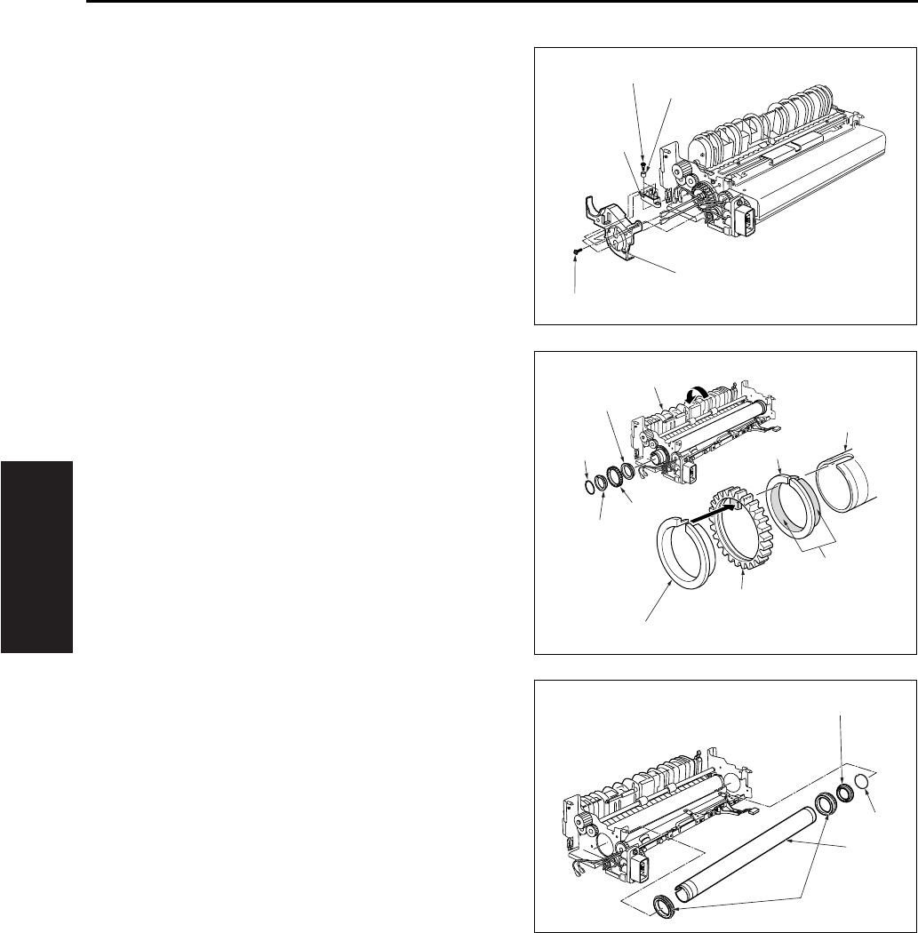
FIXING UNIT
3-60
III DIS./ASSEMBLY
B. Procedure
1. Remove the fixing unit from the main body.
2. Remove the fixing claw unit.
3. Remove the fixing web.
4. Remove the two fixing heater lamps.
5. Remove the 2 screws [2] and 2 collars [3] for the
connector [1] that was connected to the faston
terminal. Remove the connector [1].
6. Remove the 2 screws [4], and remove the lamp
support piece/R [5].
7. Open the fixing guide [1] to release the pres-
sure.
8. Remove the C-ring [3] at the rear of the heat
roller [2], and then remove the gear [4] and heat
insulating sleeve/A [5], /B [6].
9. Remove another C-ring [1], then remove the
heat insulating sleeve A [2] (the sleeve toward
the front).
10. Remove the 2 fixing bearings/U [4] (one at the
front, one at the rear) from the fixing unit.
11. Remove the fixing heat roller [3].
Note:
• When the installation, be sure that heat insulating
sleeves A and B are oriented and positioned cor-
rectly.
When replacing the heating insulating sleve/A [5],
apply solvest 240 [7] to the inside and outside
surfaces of the heat insulation sleeve/A [5] and
then install it.
[1]
[2]
[3]
[4]
[5]
[1]
[2]
[3]
[4]
[4]
[5]
[5]
[6]
[6]
[7]
[2]
[3]
[1]
[4]
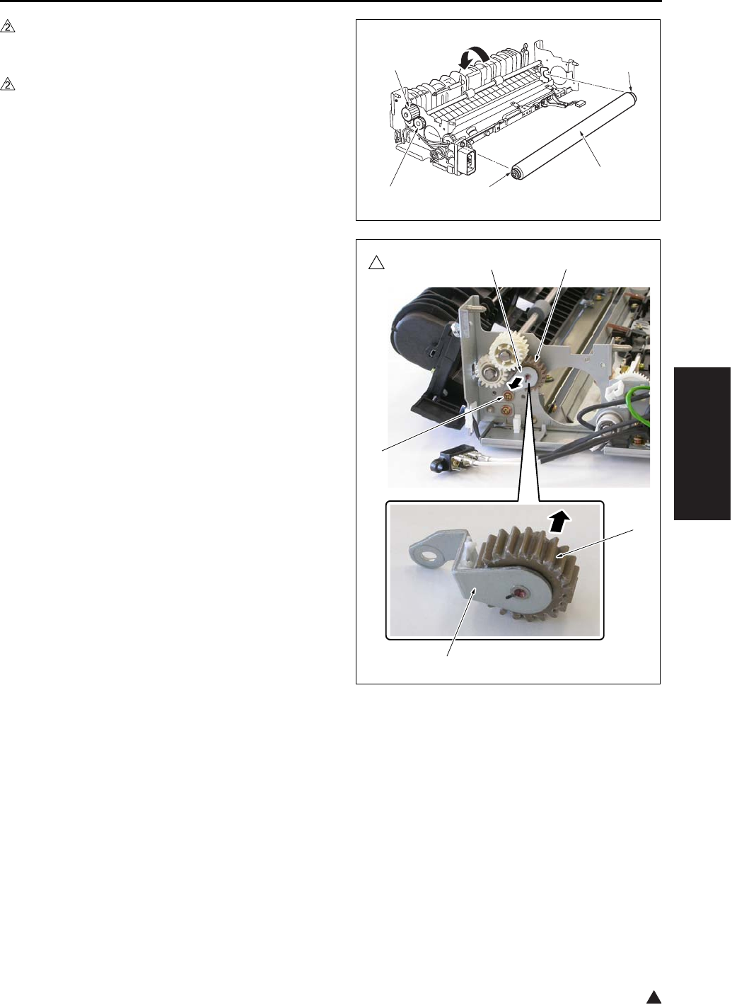
FIXING UNIT
3-61
III DIS./ASSEMBLY
2
12. After removing the fixing pressure roller [1],
remove the E-ring at both sides and then
remove the 2 fixing bearings/U [2].
13. In the case of the 7145
Remove the E-ring, and then remove the fixing
idling gear/B [4] and gear [3].
Note:
• When replacing the fixing idling gear/B [4], clean
the gear shaft with a drum cleaner.
In the case of the 7235/7228/7222
Remove a screw [1] and then remove the shaft
fixing plate caulking [2].
Remove the fixing idling gear/B [3] from the
shaft section of shaft fixing plate caulking [2].
Note:
• When replacing the fixing idling gear/B [3] with a
new one, clean the shaft section of the shaft fixing
plate caulking [2] with drum cleaner.
14. Reinstall the above parts following the removal
steps in reverse.
[1]
[2][4]
[2]
[3]
7145ma3106
2
[4]
[3]
[3][2]
[1]
[2]
7322ma3007
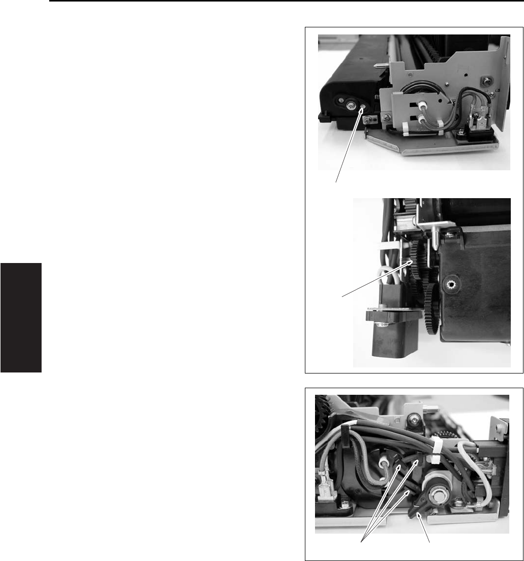
FIXING UNIT
3-62
III DIS./ASSEMBLY
Note:
• When returning the fixing web in use, be sure to
rotate the web drive gear [2] until the original web
winding shaft [1] starts to turn.
• When returning the wiring harness, be sure to
hook the wiring harness securely on the wiring
harness holder section [1] so that it does not
interfere with the web operation lever [2].
[1]
[2]
[1] [2]
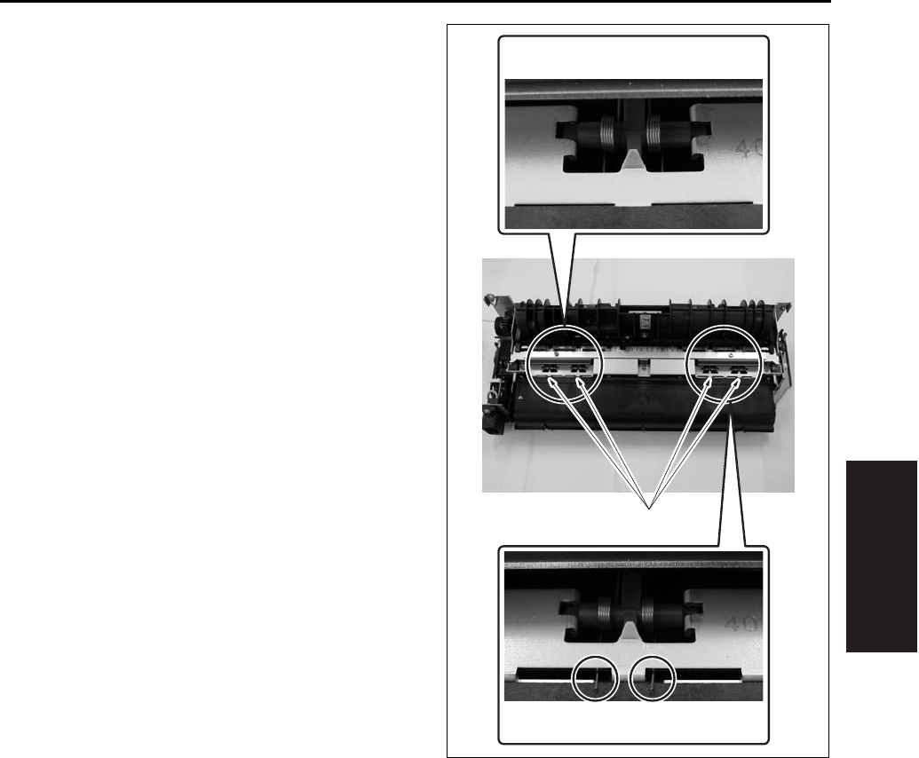
FIXING UNIT
3-63
III DIS./ASSEMBLY
• When installing the fixing claw unit, be careful
that the edge of the fixing claw pressing spring [1]
does not run on the web case.
[1]
OK
NG
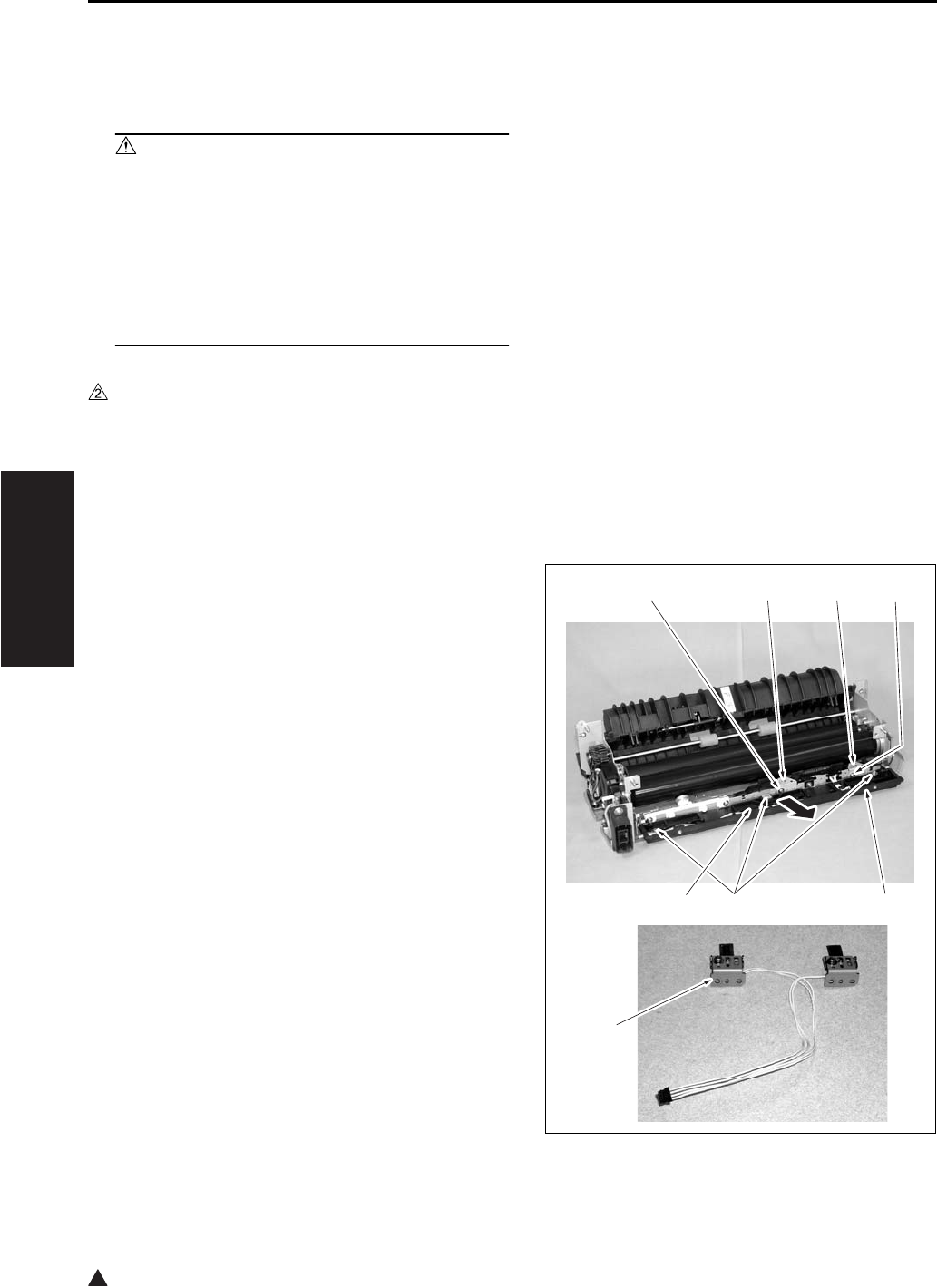
FIXING UNIT
3-64
III DIS./ASSEMBLY
2
9.6 Removing and Reinstalling
the Fixing Temperature Sen-
sors
Caution:
• After installing the fixing temperature sen-
sors:
Make sure that the wire bundles are not in
contact with the fixing heat roller.
• Make sure that the sensors them-selves (the
sensor areas) are in contact with the fixing
heat roller.
A. Periodically replaced parts/cycle
• Fixing sensor assembly: Every 480,000 copies
(7145)
• Fixing sensor assembly: Every 400,000 copies
(7235/7228/7222)
B. Procedure
1. Remove the fixing unit from the main body.
2. Remove the fixing claw unit.
3. Remove the fixing web.
4. Remove the connector [1].
5. Remove the 3 screws [2], and remove the fixing
web mounting piece [3].
6. Remove the 2 screws [4], and remove the fixing
sensor assembly [5].
7. Reinstall the above parts following the removal
steps in reverse.
Note:
• The fixing sensor assembly [7] is made up of the
TH1 (fixing temperature sensor/1) and the TH2
(fixing temperature sensor/2). Since the TH1 and
the TH2 have been adjusted at the time of their
assembling, avoid surely loosening the screws.
• Make sure that the sensors are in contact with the
heat roller.
[1]
[7]
[2] [3]
[4] [5] [6] [4]

FIXING UNIT
3-65
III DIS./ASSEMBLY
• When returning the fixing web in use, be sure to
rotate the web drive gear until the original web
winding shaft [1] starts to turn.
• When installing the fixing claw unit, be careful
that the edge of the fixing claw pressing spring [1]
does not run on the web case.
[1]
[1]
OK
NG
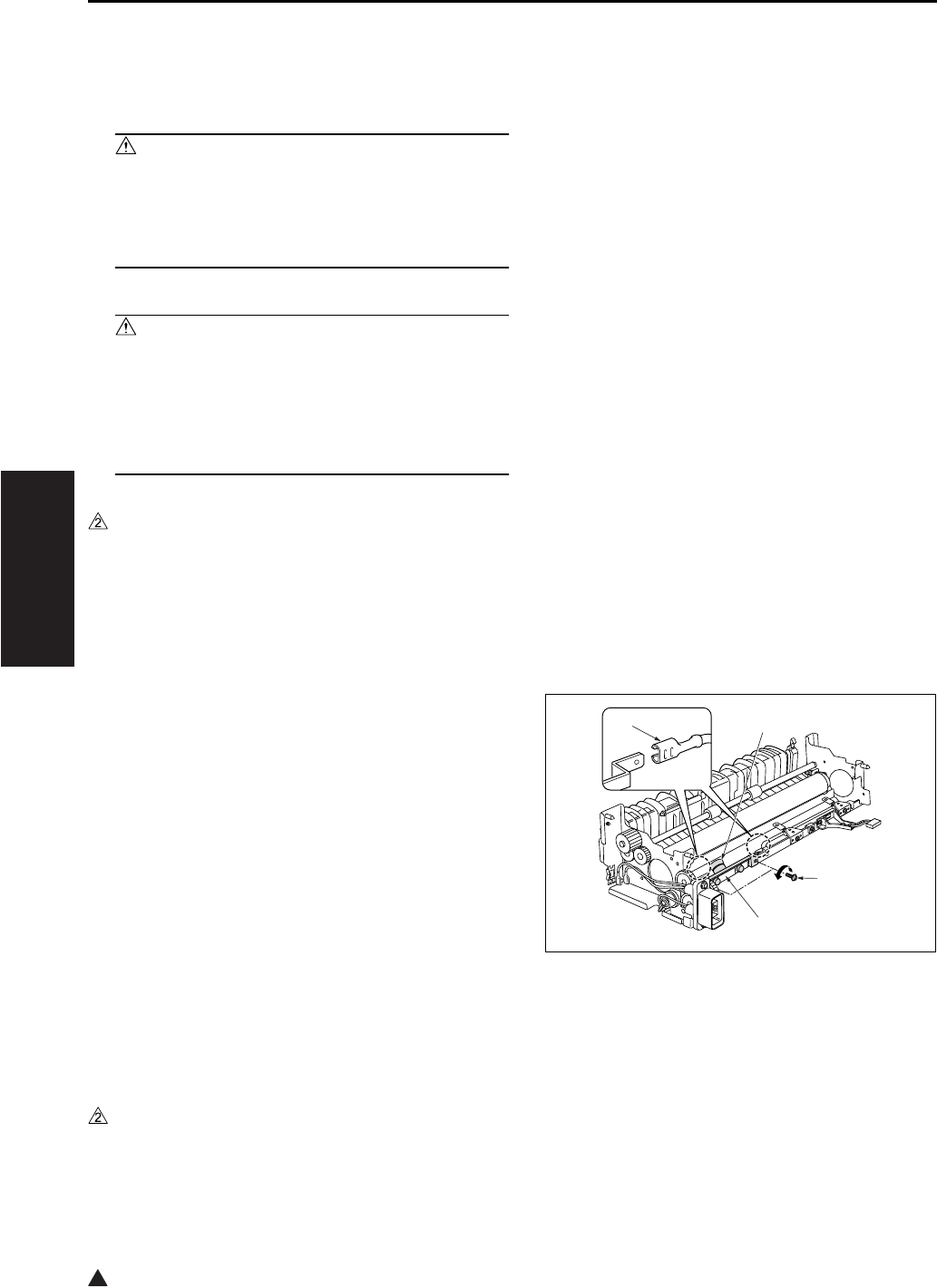
FIXING UNIT
3-66
III DIS./ASSEMBLY
2
9.7 Removing and Reinstalling
the Fuse Mounting Plate
Assembly
Caution:
• This is an important safety part. (P/N:SP00-
0110) Be sure to observe the following cau-
tions and steps when removing or reinstall-
ing.
Caution:
• After installing the thermostat:
Make sure that the wire bundle is not in con-
tact with the fixing heat roller.
• Make sure that the thermostat itself is in con-
tact with the fixing heat roller.
A. Periodically replaced parts/cycle
• Fuse mounting plate assembly: Every 480,000
copies (7145)
• Fuse mounting plate assembly: Every 400,000
copies (7235/7228/7222)
B. Procedure
1. Remove the fixing unit from the main body.
2. Remove the fixing claw unit.
3. Remove the fixing web.
4. Remove the heat roller.
5. Remove the fixing web mounting piece.
6. Detach the thermostat [1] 2 Faston terminals [2].
7. Remove the 2 screws [3], and remove the Fuse
mounting plate assembly [4].
8. Reinstall the above parts following the removal
steps in reverse.
Note:
• When installing the fuse mounting plate assem-
bly, with the base plate sandwiched between the
unit’s sheet materials, fasten it with the screw
while attaching it to the bottom side.
• When connecting the Faston terminals of the
thermostat [1], be careful not to deform the plate
spring section. Be careful not to mix up the front
with the back of the Faston terminal.
[1]
[2]
[3]
[4]
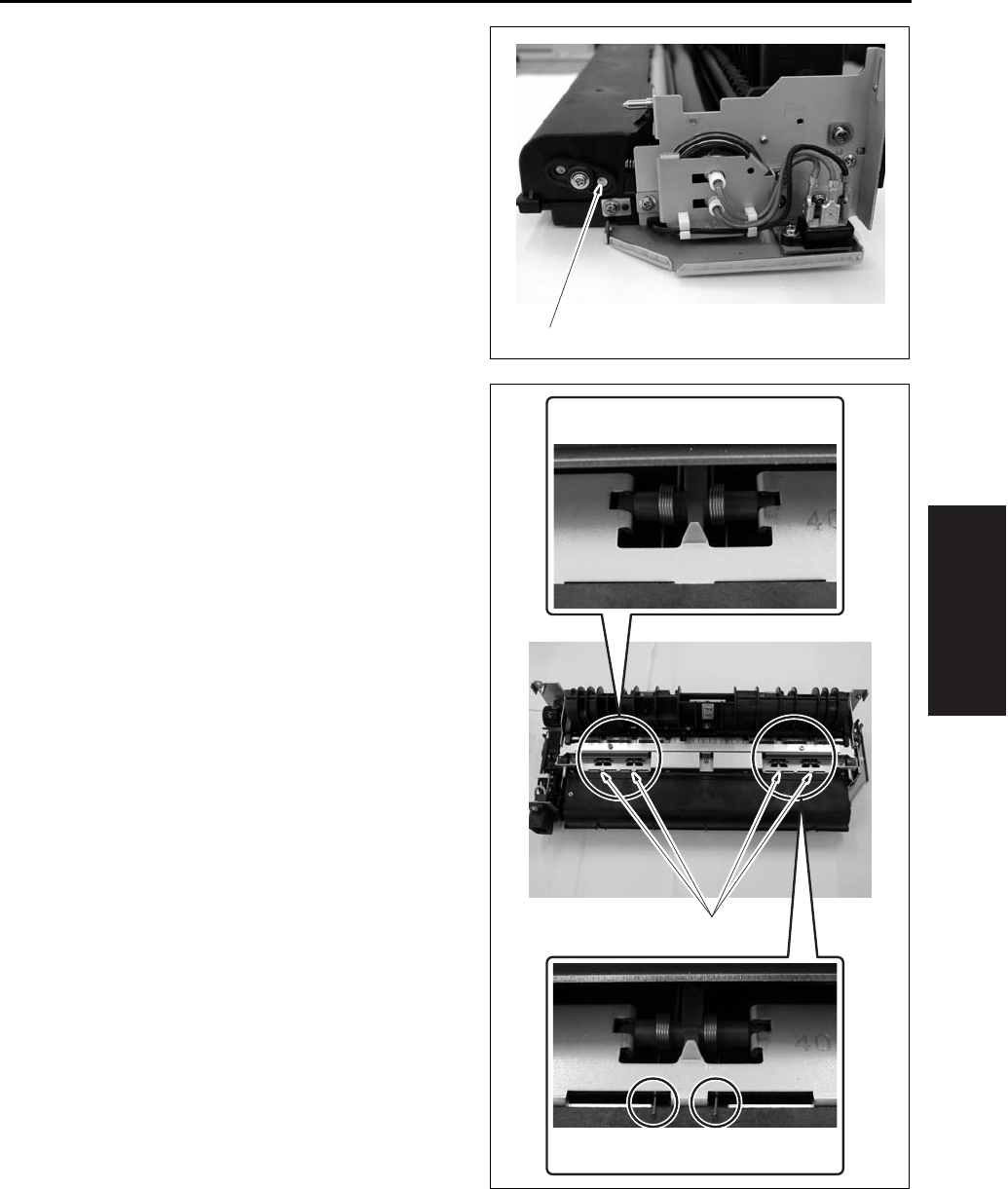
FIXING UNIT
3-67
III DIS./ASSEMBLY
• When returning the fixing web in use, be sure to
rotate the web drive gear until the original web
winding shaft [1] starts to turn after the assem-
bling.
• When installing the fixing claw unit, be careful
that the edge of the fixing claw pressing spring [1]
does not run on the web case.
[1]
[1]
OK
NG

FIXING UNIT
3-68
III DIS./ASSEMBLY
Blank page

SERVICE MANUAL
Models
7145/7222/7228/7235
Service Section
APRIL 2004
KONICA MINOLTA BUSINESS SOLUTIONS U.S.A., INC.

7145/7222/7228/7235
SERVICE MANUAL
APRIL 2004

IMPORTANT NOTICE
Because of the possible hazards to an inexperienced
person servicing this equipment, as well as the risk of
damage to the equipment, Konica Minolta Business
Solutions U.S.A., Inc. strongly recommends that all
servicing be performed by Konica Minolta-trained serv-
ice technicians only.
Changes may have been made to this equipment to
improve its performance after this service manual was
printed. Accordingly, Konica Minolta Business Solutions
U.S.A., Inc., makes no representations or warranties,
either expressed or implied, that the information con-
tained in this service manual is complete or accurate. It
is understood that the user of this manual must assume
all risks or personal injury and/or damage to the equip-
ment while servicing the equipment for which this serv-
ice manual is intended.
© 2004, KONICA MINOLTA BUSINESS SOLUTIONS U.S.A. , INC.
All rights reserved.
Printed in U.S.A.
Corporate Publications Department

CONTENTS
i
I ADJUSTMENTII ISWIII SERVICEIV DIAGRAMS
3
CONTENTS
SAFETY AND IMPORTANT WARNING ITEMS . . . . . . . . . . . . . . . . . . . . . . . . . . . . . . . . . . . . . . . . . . . . S-1
IMPORTANT NOTICE . . . . . . . . . . . . . . . . . . . . . . . . . . . . . . . . . . . . . . . . . . . . . . . . . . . . . . . . . . . . . . . S-1
DESCRIPTION ITEMS FOR DANGER, WARNING AND CAUTION . . . . . . . . . . . . . . . . . . . . . . . . . . . . S-1
SAFETY WARNINGS . . . . . . . . . . . . . . . . . . . . . . . . . . . . . . . . . . . . . . . . . . . . . . . . . . . . . . . . . . . . . . . . S-2
SAFETY INFORMATION . . . . . . . . . . . . . . . . . . . . . . . . . . . . . . . . . . . . . . . . . . . . . . . . . . . . . . . . . . . . . S-10
IMPORTANT INFORMATION . . . . . . . . . . . . . . . . . . . . . . . . . . . . . . . . . . . . . . . . . . . . . . . . . . . . . . . . . S-10
SAFETY CIRCUITS . . . . . . . . . . . . . . . . . . . . . . . . . . . . . . . . . . . . . . . . . . . . . . . . . . . . . . . . . . . . . . . . S-11
INDICATION OF WARNING ON THE MACHINE . . . . . . . . . . . . . . . . . . . . . . . . . . . . . . . . . . . . . . . . . . S-13
I ADJUSTMENT
1. HOW TO USE THE ADJUSTMENT SECTION . . . . . . . . . . . . . . . . . . . . . . . . . . . . . . . . . . . . . . . . . . 1-1
1.1 Composition. . . . . . . . . . . . . . . . . . . . . . . . . . . . . . . . . . . . . . . . . . . . . . . . . . . . . . . . . . . . . . . . . . 1-1
2. ADJUSTMENTS WHEN REPLACING PARTS . . . . . . . . . . . . . . . . . . . . . . . . . . . . . . . . . . . . . . . . . . 1-1
3. LIST OF ADJUSTMENT ITEMS . . . . . . . . . . . . . . . . . . . . . . . . . . . . . . . . . . . . . . . . . . . . . . . . . . . . . . 1-2
4. CE PASSWORD SETTING . . . . . . . . . . . . . . . . . . . . . . . . . . . . . . . . . . . . . . . . . . . . . . . . . . . . . . . . . 1-4
5. MODE CHANGE MENU . . . . . . . . . . . . . . . . . . . . . . . . . . . . . . . . . . . . . . . . . . . . . . . . . . . . . . . . . . . . 1-4
5.1 Setting method . . . . . . . . . . . . . . . . . . . . . . . . . . . . . . . . . . . . . . . . . . . . . . . . . . . . . . . . . . . . . . . 1-4
6. CHECKING BY THE COUNTER KEY FUNCTION . . . . . . . . . . . . . . . . . . . . . . . . . . . . . . . . . . . . . . . 1-5
6.1 Checking method of the counter key function . . . . . . . . . . . . . . . . . . . . . . . . . . . . . . . . . . . . . . . . 1-5
7. 25 MODE . . . . . . . . . . . . . . . . . . . . . . . . . . . . . . . . . . . . . . . . . . . . . . . . . . . . . . . . . . . . . . . . . . . . . . . 1-6
7.1 Setting method . . . . . . . . . . . . . . . . . . . . . . . . . . . . . . . . . . . . . . . . . . . . . . . . . . . . . . . . . . . . . . . 1-8
7.2 Setting software DIPSW . . . . . . . . . . . . . . . . . . . . . . . . . . . . . . . . . . . . . . . . . . . . . . . . . . . . . . . . 1-8
7.3 PM count setting . . . . . . . . . . . . . . . . . . . . . . . . . . . . . . . . . . . . . . . . . . . . . . . . . . . . . . . . . . . . . 1-30
7.3.1 PM count reset . . . . . . . . . . . . . . . . . . . . . . . . . . . . . . . . . . . . . . . . . . . . . . . . . . . . . . . . . . 1-30
7.3.2 Entering PM count start date . . . . . . . . . . . . . . . . . . . . . . . . . . . . . . . . . . . . . . . . . . . . . . . 1-30
7.3.3 Setting of PM cycle . . . . . . . . . . . . . . . . . . . . . . . . . . . . . . . . . . . . . . . . . . . . . . . . . . . . . . 1-30
7.3.4 Counter clear . . . . . . . . . . . . . . . . . . . . . . . . . . . . . . . . . . . . . . . . . . . . . . . . . . . . . . . . . . . 1-30
7.4 Data collection . . . . . . . . . . . . . . . . . . . . . . . . . . . . . . . . . . . . . . . . . . . . . . . . . . . . . . . . . . . . . . . 1-31
7.5 Copy count for each part to be replaced . . . . . . . . . . . . . . . . . . . . . . . . . . . . . . . . . . . . . . . . . . . 1-37
7.5.1 Copy count by parts to be replaced (fixed). . . . . . . . . . . . . . . . . . . . . . . . . . . . . . . . . . . . . 1-37
7.5.2 Copy count by parts to be replaced (Named; arbitrarily) . . . . . . . . . . . . . . . . . . . . . . . . . . 1-39
7.6 Password setting . . . . . . . . . . . . . . . . . . . . . . . . . . . . . . . . . . . . . . . . . . . . . . . . . . . . . . . . . . . . . 1-41
7.7 Setting phone number of the service center . . . . . . . . . . . . . . . . . . . . . . . . . . . . . . . . . . . . . . . . 1-42
7.8 Setting the serial number/the destination . . . . . . . . . . . . . . . . . . . . . . . . . . . . . . . . . . . . . . . . . . 1-42
7.8.1 Setting the serial number . . . . . . . . . . . . . . . . . . . . . . . . . . . . . . . . . . . . . . . . . . . . . . . . . . 1-42
7.8.2 Setting the destination . . . . . . . . . . . . . . . . . . . . . . . . . . . . . . . . . . . . . . . . . . . . . . . . . . . . 1-43
7.9 Displaying the ROM version . . . . . . . . . . . . . . . . . . . . . . . . . . . . . . . . . . . . . . . . . . . . . . . . . . . . 1-43
7.10 KRDS setting . . . . . . . . . . . . . . . . . . . . . . . . . . . . . . . . . . . . . . . . . . . . . . . . . . . . . . . . . . . . . . . . 1-43
7.11 ISW setting . . . . . . . . . . . . . . . . . . . . . . . . . . . . . . . . . . . . . . . . . . . . . . . . . . . . . . . . . . . . . . . . . 1-43
7.12 Root counter display . . . . . . . . . . . . . . . . . . . . . . . . . . . . . . . . . . . . . . . . . . . . . . . . . . . . . . . . . . 1-43
7.13 Setting date . . . . . . . . . . . . . . . . . . . . . . . . . . . . . . . . . . . . . . . . . . . . . . . . . . . . . . . . . . . . . . . . . 1-44
7.14 Tray size setting . . . . . . . . . . . . . . . . . . . . . . . . . . . . . . . . . . . . . . . . . . . . . . . . . . . . . . . . . . . . . 1-44

CONTENTS
ii
I ADJUSTMENTII ISWIII SERVICE
IV DIAGRAMS
3
8. 36 MODE . . . . . . . . . . . . . . . . . . . . . . . . . . . . . . . . . . . . . . . . . . . . . . . . . . . . . . . . . . . . . . . . . . . . . . 1-45
8.1 Setting method. . . . . . . . . . . . . . . . . . . . . . . . . . . . . . . . . . . . . . . . . . . . . . . . . . . . . . . . . . . . . . . 1-45
8.2 Process adjustment . . . . . . . . . . . . . . . . . . . . . . . . . . . . . . . . . . . . . . . . . . . . . . . . . . . . . . . . . . . 1-45
8.3 L detection adjustment. . . . . . . . . . . . . . . . . . . . . . . . . . . . . . . . . . . . . . . . . . . . . . . . . . . . . . . . . 1-46
8.4 Toner density adjustment. . . . . . . . . . . . . . . . . . . . . . . . . . . . . . . . . . . . . . . . . . . . . . . . . . . . . . . 1-46
8.5 Dot diameter adjustment . . . . . . . . . . . . . . . . . . . . . . . . . . . . . . . . . . . . . . . . . . . . . . . . . . . . . . . 1-47
8.6 LD1 offset adjustment . . . . . . . . . . . . . . . . . . . . . . . . . . . . . . . . . . . . . . . . . . . . . . . . . . . . . . . . . 1-47
8.7 LD2 offset adjustment (7145 only) . . . . . . . . . . . . . . . . . . . . . . . . . . . . . . . . . . . . . . . . . . . . . . . . 1-48
8.8 Timing adjustment . . . . . . . . . . . . . . . . . . . . . . . . . . . . . . . . . . . . . . . . . . . . . . . . . . . . . . . . . . . . 1-49
8.8.1 Vertical/Horizontal magnification adjustment . . . . . . . . . . . . . . . . . . . . . . . . . . . . . . . . . . . 1-49
8.8.2 Restart timing adjustment. . . . . . . . . . . . . . . . . . . . . . . . . . . . . . . . . . . . . . . . . . . . . . . . . . 1-52
8.8.3 Paper feed loop amount adjustment. . . . . . . . . . . . . . . . . . . . . . . . . . . . . . . . . . . . . . . . . . 1-54
8.8.4 Leading edge original erasure adjustment . . . . . . . . . . . . . . . . . . . . . . . . . . . . . . . . . . . . . 1-55
8.8.5 Centering adjustment . . . . . . . . . . . . . . . . . . . . . . . . . . . . . . . . . . . . . . . . . . . . . . . . . . . . . 1-56
8.8.6 Image read point adjustment . . . . . . . . . . . . . . . . . . . . . . . . . . . . . . . . . . . . . . . . . . . . . . . 1-58
8.8.7 Recall standard data. . . . . . . . . . . . . . . . . . . . . . . . . . . . . . . . . . . . . . . . . . . . . . . . . . . . . . 1-59
8.9 Running test mode. . . . . . . . . . . . . . . . . . . . . . . . . . . . . . . . . . . . . . . . . . . . . . . . . . . . . . . . . . . . 1-59
8.9.1 Setting method . . . . . . . . . . . . . . . . . . . . . . . . . . . . . . . . . . . . . . . . . . . . . . . . . . . . . . . . . . 1-60
8.10 Test pattern output. . . . . . . . . . . . . . . . . . . . . . . . . . . . . . . . . . . . . . . . . . . . . . . . . . . . . . . . . . . . 1-60
8.11 Test pattern density adjustment. . . . . . . . . . . . . . . . . . . . . . . . . . . . . . . . . . . . . . . . . . . . . . . . . . 1-65
8.12 Image quality adjustment . . . . . . . . . . . . . . . . . . . . . . . . . . . . . . . . . . . . . . . . . . . . . . . . . . . . . . . 1-65
8.12.1 RADF scanning density adjustment . . . . . . . . . . . . . . . . . . . . . . . . . . . . . . . . . . . . . . . . . . 1-65
8.12.2 Non-image area erase check . . . . . . . . . . . . . . . . . . . . . . . . . . . . . . . . . . . . . . . . . . . . . . . 1-66
8.13 List print . . . . . . . . . . . . . . . . . . . . . . . . . . . . . . . . . . . . . . . . . . . . . . . . . . . . . . . . . . . . . . . . . . . . 1-67
8.14 Counter clear . . . . . . . . . . . . . . . . . . . . . . . . . . . . . . . . . . . . . . . . . . . . . . . . . . . . . . . . . . . . . . . . 1-68
8.15 Adjustment of RADF . . . . . . . . . . . . . . . . . . . . . . . . . . . . . . . . . . . . . . . . . . . . . . . . . . . . . . . . . . 1-68
8.15.1 Vertical magnification adjustment in RADF system . . . . . . . . . . . . . . . . . . . . . . . . . . . . . . 1-68
8.15.2 Adjustment of restart timing . . . . . . . . . . . . . . . . . . . . . . . . . . . . . . . . . . . . . . . . . . . . . . . . 1-69
8.15.3 Paper feed loop adjustment . . . . . . . . . . . . . . . . . . . . . . . . . . . . . . . . . . . . . . . . . . . . . . . . 1-70
8.15.4 Centering adjustment . . . . . . . . . . . . . . . . . . . . . . . . . . . . . . . . . . . . . . . . . . . . . . . . . . . . . 1-70
8.15.5 RADF scanning density adjustment . . . . . . . . . . . . . . . . . . . . . . . . . . . . . . . . . . . . . . . . . . 1-71
8.15.6 RADF image read point adjustment . . . . . . . . . . . . . . . . . . . . . . . . . . . . . . . . . . . . . . . . . . 1-71
8.16 FNS adjustment (FS-112 only) . . . . . . . . . . . . . . . . . . . . . . . . . . . . . . . . . . . . . . . . . . . . . . . . . . 1-71
8.17 FNS adjustment (FS-114 only) . . . . . . . . . . . . . . . . . . . . . . . . . . . . . . . . . . . . . . . . . . . . . . . . . . 1-72
8.17.1 Fold & Stitch position adjustment (SK-114) . . . . . . . . . . . . . . . . . . . . . . . . . . . . . . . . . . . . 1-72
8.17.2 Fold position adjustment (SK-114) . . . . . . . . . . . . . . . . . . . . . . . . . . . . . . . . . . . . . . . . . . . 1-73
8.17.3 Punch position adjustment (PK-114) . . . . . . . . . . . . . . . . . . . . . . . . . . . . . . . . . . . . . . . . . 1-73
8.17.4 Punch loop adjustment (PK-114) . . . . . . . . . . . . . . . . . . . . . . . . . . . . . . . . . . . . . . . . . . . . 1-74
9. 47 MODE . . . . . . . . . . . . . . . . . . . . . . . . . . . . . . . . . . . . . . . . . . . . . . . . . . . . . . . . . . . . . . . . . . . . . . 1-76
9.1 47 mode setting method . . . . . . . . . . . . . . . . . . . . . . . . . . . . . . . . . . . . . . . . . . . . . . . . . . . . . . . 1-76
9.2 RADF original size detection . . . . . . . . . . . . . . . . . . . . . . . . . . . . . . . . . . . . . . . . . . . . . . . . . . . . 1-77
9.3 Bypass size detection adjustment . . . . . . . . . . . . . . . . . . . . . . . . . . . . . . . . . . . . . . . . . . . . . . . . 1-77
9.4 Action for mounting when reinstalling the HDD . . . . . . . . . . . . . . . . . . . . . . . . . . . . . . . . . . . . . . 1-77
9.5 Input check list . . . . . . . . . . . . . . . . . . . . . . . . . . . . . . . . . . . . . . . . . . . . . . . . . . . . . . . . . . . . . . . 1-78
9.6 Output check list . . . . . . . . . . . . . . . . . . . . . . . . . . . . . . . . . . . . . . . . . . . . . . . . . . . . . . . . . . . . . 1-84
10. OTHER ADJUSTMENTS . . . . . . . . . . . . . . . . . . . . . . . . . . . . . . . . . . . . . . . . . . . . . . . . . . . . . . . . . . 1-89
10.1 RADF height adjustment . . . . . . . . . . . . . . . . . . . . . . . . . . . . . . . . . . . . . . . . . . . . . . . . . . . . . . . 1-89

CONTENTS
iii
I ADJUSTMENTII ISWIII SERVICEIV DIAGRAMS
3
10.2 RADF distortion adjustment. . . . . . . . . . . . . . . . . . . . . . . . . . . . . . . . . . . . . . . . . . . . . . . . . . . . . 1-90
10.3 RADF original skew adjustment (front side) . . . . . . . . . . . . . . . . . . . . . . . . . . . . . . . . . . . . . . . . 1-91
10.4 RADF original skew adjustment (back side) . . . . . . . . . . . . . . . . . . . . . . . . . . . . . . . . . . . . . . . . 1-92
10.5 DB-411 paper-centering adjustment . . . . . . . . . . . . . . . . . . . . . . . . . . . . . . . . . . . . . . . . . . . . . . 1-94
10.6 DB-411 tray tilt adjustment . . . . . . . . . . . . . . . . . . . . . . . . . . . . . . . . . . . . . . . . . . . . . . . . . . . . . 1-95
10.7 LT tray tilt adjustment . . . . . . . . . . . . . . . . . . . . . . . . . . . . . . . . . . . . . . . . . . . . . . . . . . . . . . . . . 1-96
10.8 FS-113 Output Check Mode . . . . . . . . . . . . . . . . . . . . . . . . . . . . . . . . . . . . . . . . . . . . . . . . . . . . 1-98
10.9 Lengthwise position adjustment of punch hole of FS-113 . . . . . . . . . . . . . . . . . . . . . . . . . . . . . 1-103
10.10Adjustment of FS-113 Solenoids . . . . . . . . . . . . . . . . . . . . . . . . . . . . . . . . . . . . . . . . . . . . . . . . 1-104
10.11FS-113 Timing Belt Tension Adjustment . . . . . . . . . . . . . . . . . . . . . . . . . . . . . . . . . . . . . . . . . . 1-105
10.12FS-113 Adjustment of the Elevator Tray Upper Limit Sensor . . . . . . . . . . . . . . . . . . . . . . . . . . 1-106
10.13Adjustment of FS-113 Elevator Tray Overload Detection Level . . . . . . . . . . . . . . . . . . . . . . . . 1-107
10.14Staple Position Adjustment of FS-114. . . . . . . . . . . . . . . . . . . . . . . . . . . . . . . . . . . . . . . . . . . . 1-108
10.15Adjustment of the Installation Position of the Shutter Drive Gear of FS-114. . . . . . . . . . . . . . . 1-109
10.16Punch Hole Deviance Adjustment of FS-114 (PK-114). . . . . . . . . . . . . . . . . . . . . . . . . . . . . . . 1-110
10.17Fold Angle Adjustment of SK-114 . . . . . . . . . . . . . . . . . . . . . . . . . . . . . . . . . . . . . . . . . . . . . . . 1-111
10.18Staple Angle Adjustment of SK-114 . . . . . . . . . . . . . . . . . . . . . . . . . . . . . . . . . . . . . . . . . . . . . 1-112
II ISW
1. DESCRIPTION OF THE ISW . . . . . . . . . . . . . . . . . . . . . . . . . . . . . . . . . . . . . . . . . . . . . . . . . . . . . . . . 2-1
2. SETUP . . . . . . . . . . . . . . . . . . . . . . . . . . . . . . . . . . . . . . . . . . . . . . . . . . . . . . . . . . . . . . . . . . . . . . . . . 2-1
3. USB ISW. . . . . . . . . . . . . . . . . . . . . . . . . . . . . . . . . . . . . . . . . . . . . . . . . . . . . . . . . . . . . . . . . . . . . . . . 2-5
III SERVICE
1. SERVICE SCHEDULE . . . . . . . . . . . . . . . . . . . . . . . . . . . . . . . . . . . . . . . . . . . . . . . . . . . . . . . . . . . . . 3-1
1.1 Service schedule . . . . . . . . . . . . . . . . . . . . . . . . . . . . . . . . . . . . . . . . . . . . . . . . . . . . . . . . . . . . . . 3-1
1.1.1 7145 . . . . . . . . . . . . . . . . . . . . . . . . . . . . . . . . . . . . . . . . . . . . . . . . . . . . . . . . . . . . . . . . . . . 3-1
1.1.2 7235 . . . . . . . . . . . . . . . . . . . . . . . . . . . . . . . . . . . . . . . . . . . . . . . . . . . . . . . . . . . . . . . . . . . 3-2
1.1.3 7228/7222 . . . . . . . . . . . . . . . . . . . . . . . . . . . . . . . . . . . . . . . . . . . . . . . . . . . . . . . . . . . . . . 3-3
1.2 Maintenance items . . . . . . . . . . . . . . . . . . . . . . . . . . . . . . . . . . . . . . . . . . . . . . . . . . . . . . . . . . . . 3-5
1.2.1 7145 . . . . . . . . . . . . . . . . . . . . . . . . . . . . . . . . . . . . . . . . . . . . . . . . . . . . . . . . . . . . . . . . . . . 3-5
1.2.2 7235/7228/7222 . . . . . . . . . . . . . . . . . . . . . . . . . . . . . . . . . . . . . . . . . . . . . . . . . . . . . . . . . . 3-6
1.2.3 DF-318/320 . . . . . . . . . . . . . . . . . . . . . . . . . . . . . . . . . . . . . . . . . . . . . . . . . . . . . . . . . . . . . 3-7
1.2.4 DB-211/411 . . . . . . . . . . . . . . . . . . . . . . . . . . . . . . . . . . . . . . . . . . . . . . . . . . . . . . . . . . . . . 3-8
1.2.5 LT-203 . . . . . . . . . . . . . . . . . . . . . . . . . . . . . . . . . . . . . . . . . . . . . . . . . . . . . . . . . . . . . . . . . 3-8
1.2.6 FS-112 . . . . . . . . . . . . . . . . . . . . . . . . . . . . . . . . . . . . . . . . . . . . . . . . . . . . . . . . . . . . . . . . . 3-8
1.2.7 FS-113/RU-101 . . . . . . . . . . . . . . . . . . . . . . . . . . . . . . . . . . . . . . . . . . . . . . . . . . . . . . . . . . 3-9
1.2.8 FS-114 . . . . . . . . . . . . . . . . . . . . . . . . . . . . . . . . . . . . . . . . . . . . . . . . . . . . . . . . . . . . . . . . . 3-9
1.2.9 PK-114 . . . . . . . . . . . . . . . . . . . . . . . . . . . . . . . . . . . . . . . . . . . . . . . . . . . . . . . . . . . . . . . . . 3-9
1.2.10 SK-114 . . . . . . . . . . . . . . . . . . . . . . . . . . . . . . . . . . . . . . . . . . . . . . . . . . . . . . . . . . . . . . . . 3-10
1.2.11 BK-114 . . . . . . . . . . . . . . . . . . . . . . . . . . . . . . . . . . . . . . . . . . . . . . . . . . . . . . . . . . . . . . . . 3-10
1.3 Periodic check items . . . . . . . . . . . . . . . . . . . . . . . . . . . . . . . . . . . . . . . . . . . . . . . . . . . . . . . . . . 3-11
1.3.1 7145 . . . . . . . . . . . . . . . . . . . . . . . . . . . . . . . . . . . . . . . . . . . . . . . . . . . . . . . . . . . . . . . . . . 3-11
1.3.2 7235/7228/7222 . . . . . . . . . . . . . . . . . . . . . . . . . . . . . . . . . . . . . . . . . . . . . . . . . . . . . . . . . 3-13
1.3.3 DF-318 . . . . . . . . . . . . . . . . . . . . . . . . . . . . . . . . . . . . . . . . . . . . . . . . . . . . . . . . . . . . . . . . 3-15
1.3.4 DF-320 . . . . . . . . . . . . . . . . . . . . . . . . . . . . . . . . . . . . . . . . . . . . . . . . . . . . . . . . . . . . . . . . 3-15

CONTENTS
iv
I ADJUSTMENTII ISWIII SERVICE
IV DIAGRAMS
3
1.3.5 DB-211 . . . . . . . . . . . . . . . . . . . . . . . . . . . . . . . . . . . . . . . . . . . . . . . . . . . . . . . . . . . . . . . . 3-16
1.3.6 DB-411 . . . . . . . . . . . . . . . . . . . . . . . . . . . . . . . . . . . . . . . . . . . . . . . . . . . . . . . . . . . . . . . . 3-16
1.3.7 LT-203 . . . . . . . . . . . . . . . . . . . . . . . . . . . . . . . . . . . . . . . . . . . . . . . . . . . . . . . . . . . . . . . . 3-16
1.3.8 FS-112 . . . . . . . . . . . . . . . . . . . . . . . . . . . . . . . . . . . . . . . . . . . . . . . . . . . . . . . . . . . . . . . . 3-17
1.4 Replacement parts list . . . . . . . . . . . . . . . . . . . . . . . . . . . . . . . . . . . . . . . . . . . . . . . . . . . . . . . . . 3-18
1.5 Important maintenance parts . . . . . . . . . . . . . . . . . . . . . . . . . . . . . . . . . . . . . . . . . . . . . . . . . . . . 3-20
2. 1 PM PARTS KIT . . . . . . . . . . . . . . . . . . . . . . . . . . . . . . . . . . . . . . . . . . . . . . . . . . . . . . . . . . . . . . . . 3-21
3. SERVICE MATERIALS LIST . . . . . . . . . . . . . . . . . . . . . . . . . . . . . . . . . . . . . . . . . . . . . . . . . . . . . . . 3-22
4. CE TOOLS LIST . . . . . . . . . . . . . . . . . . . . . . . . . . . . . . . . . . . . . . . . . . . . . . . . . . . . . . . . . . . . . . . . . 3-23
IV DIAGRAMS
1. PARTS LAYOUT DRAWING . . . . . . . . . . . . . . . . . . . . . . . . . . . . . . . . . . . . . . . . . . . . . . . . . . . . . . . . 4-1
1.1 Main body parts layout drawing . . . . . . . . . . . . . . . . . . . . . . . . . . . . . . . . . . . . . . . . . . . . . . . . . . . 4-1
1.2 DF-318/320 parts layout drawing. . . . . . . . . . . . . . . . . . . . . . . . . . . . . . . . . . . . . . . . . . . . . . . . . 4-14
1.3 DB-211 parts layout drawing . . . . . . . . . . . . . . . . . . . . . . . . . . . . . . . . . . . . . . . . . . . . . . . . . . . . 4-15
1.4 DB-411 parts layout drawing . . . . . . . . . . . . . . . . . . . . . . . . . . . . . . . . . . . . . . . . . . . . . . . . . . . . 4-16
1.5 LT-203 parts layout drawing . . . . . . . . . . . . . . . . . . . . . . . . . . . . . . . . . . . . . . . . . . . . . . . . . . . . 4-17
1.6 FS-112 parts layout drawing . . . . . . . . . . . . . . . . . . . . . . . . . . . . . . . . . . . . . . . . . . . . . . . . . . . . 4-18
1.7 RU-101 parts layout drawing . . . . . . . . . . . . . . . . . . . . . . . . . . . . . . . . . . . . . . . . . . . . . . . . . . . . 4-21
1.8 IT-101 parts layout drawing . . . . . . . . . . . . . . . . . . . . . . . . . . . . . . . . . . . . . . . . . . . . . . . . . . . . . 4-21
2. CONNECTOR LAYOUT DRAWING . . . . . . . . . . . . . . . . . . . . . . . . . . . . . . . . . . . . . . . . . . . . . . . . . . 4-22
2.1 Main body connector layout drawing . . . . . . . . . . . . . . . . . . . . . . . . . . . . . . . . . . . . . . . . . . . . . . 4-22
2.2 DF-318/320 connector layout drawing . . . . . . . . . . . . . . . . . . . . . . . . . . . . . . . . . . . . . . . . . . . . . 4-28
2.3 DB-211 connector layout drawing . . . . . . . . . . . . . . . . . . . . . . . . . . . . . . . . . . . . . . . . . . . . . . . . 4-28
2.4 DB-411 connector layout drawing . . . . . . . . . . . . . . . . . . . . . . . . . . . . . . . . . . . . . . . . . . . . . . . . 4-29
2.5 LT-203 connector layout drawing. . . . . . . . . . . . . . . . . . . . . . . . . . . . . . . . . . . . . . . . . . . . . . . . . 4-29
2.6 FS-112 connector layout drawing . . . . . . . . . . . . . . . . . . . . . . . . . . . . . . . . . . . . . . . . . . . . . . . . 4-30
2.7 RU-101 connector layout drawing . . . . . . . . . . . . . . . . . . . . . . . . . . . . . . . . . . . . . . . . . . . . . . . . 4-30
3. JAM CODE LIST . . . . . . . . . . . . . . . . . . . . . . . . . . . . . . . . . . . . . . . . . . . . . . . . . . . . . . . . . . . . . . . . . 4-31
4. ERROR CODE LIST . . . . . . . . . . . . . . . . . . . . . . . . . . . . . . . . . . . . . . . . . . . . . . . . . . . . . . . . . . . . . . 4-39
4.1 Error code list. . . . . . . . . . . . . . . . . . . . . . . . . . . . . . . . . . . . . . . . . . . . . . . . . . . . . . . . . . . . . . . . 4-39
4.2 About abnormal units isolation. . . . . . . . . . . . . . . . . . . . . . . . . . . . . . . . . . . . . . . . . . . . . . . . . . . 4-73
4.3 L detection error code list. . . . . . . . . . . . . . . . . . . . . . . . . . . . . . . . . . . . . . . . . . . . . . . . . . . . . . . 4-74
4.4 Network section status indication. . . . . . . . . . . . . . . . . . . . . . . . . . . . . . . . . . . . . . . . . . . . . . . . . 4-74
5. TIMING CHART . . . . . . . . . . . . . . . . . . . . . . . . . . . . . . . . . . . . . . . . . . . . . . . . . . . . . . . . . . . . . . . . . 4-75
5.1 7145 timing chart . . . . . . . . . . . . . . . . . . . . . . . . . . . . . . . . . . . . . . . . . . . . . . . . . . . . . . . . . . . . . 4-75
5.2 7235/7228/7222 timing chart . . . . . . . . . . . . . . . . . . . . . . . . . . . . . . . . . . . . . . . . . . . . . . . . . . . . 4-76
5.3 7145 ADU timing chart. . . . . . . . . . . . . . . . . . . . . . . . . . . . . . . . . . . . . . . . . . . . . . . . . . . . . . . . . 4-77
5.4 7235/7228/7222 ADU timing chart. . . . . . . . . . . . . . . . . . . . . . . . . . . . . . . . . . . . . . . . . . . . . . . . 4-78
5.5 DF-318/DF-320 timing chart . . . . . . . . . . . . . . . . . . . . . . . . . . . . . . . . . . . . . . . . . . . . . . . . . . . . 4-79
5.6 DB-211/DB-411 timing chart . . . . . . . . . . . . . . . . . . . . . . . . . . . . . . . . . . . . . . . . . . . . . . . . . . . . 4-81
5.7 LT-203 timing chart . . . . . . . . . . . . . . . . . . . . . . . . . . . . . . . . . . . . . . . . . . . . . . . . . . . . . . . . . . . 4-82
5.8 FS-112 timing chart . . . . . . . . . . . . . . . . . . . . . . . . . . . . . . . . . . . . . . . . . . . . . . . . . . . . . . . . . . . 4-83
5.9 FS-113 timing chart . . . . . . . . . . . . . . . . . . . . . . . . . . . . . . . . . . . . . . . . . . . . . . . . . . . . . . . . . . . 4-85
5.10 FS-114 timing chart . . . . . . . . . . . . . . . . . . . . . . . . . . . . . . . . . . . . . . . . . . . . . . . . . . . . . . . . . . . 4-89
5.11 SK-114 timing chart . . . . . . . . . . . . . . . . . . . . . . . . . . . . . . . . . . . . . . . . . . . . . . . . . . . . . . . . . . . 4-91
6. OVERALL WIRING DIAGRAM . . . . . . . . . . . . . . . . . . . . . . . . . . . . . . . . . . . . . . . . . . . . . . . . . . . . . . 4-93

CONTENTS
v
I ADJUSTMENTII ISWIII SERVICEIV DIAGRAMS
3
6.1 DF-318/320 Overall Wiring Diagram . . . . . . . . . . . . . . . . . . . . . . . . . . . . . . . . . . . . . . . . . . . . . . 4-93
6.2 DB-211/411 Overall Wiring Diagram . . . . . . . . . . . . . . . . . . . . . . . . . . . . . . . . . . . . . . . . . . . . . . 4-94
6.3 LT-203 Overall Wiring Diagram . . . . . . . . . . . . . . . . . . . . . . . . . . . . . . . . . . . . . . . . . . . . . . . . . . 4-95
6.4 FS-112 Overall Wiring Diagram. . . . . . . . . . . . . . . . . . . . . . . . . . . . . . . . . . . . . . . . . . . . . . . . . . 4-97
6.5 RU-101 Overall Wiring Diagram . . . . . . . . . . . . . . . . . . . . . . . . . . . . . . . . . . . . . . . . . . . . . . . . . 4-99
6.6 FS-113 Overall Wiring Diagram. . . . . . . . . . . . . . . . . . . . . . . . . . . . . . . . . . . . . . . . . . . . . . . . . 4-101
6.7 SK-114 Overall Wiring Diagram . . . . . . . . . . . . . . . . . . . . . . . . . . . . . . . . . . . . . . . . . . . . . . . . 4-103
7. APPENDIX
7.1 7145 Overall Wiring Diagram (1/4) . . . . . . . . . . . . . . . . . . . . . . . . . . . . . . . . . . . . . . . . . . Appendix-1
7.2 7145 Overall Wiring Diagram (2/4) . . . . . . . . . . . . . . . . . . . . . . . . . . . . . . . . . . . . . . . . . . Appendix-2
7.3 7145 Overall Wiring Diagram (3/4) . . . . . . . . . . . . . . . . . . . . . . . . . . . . . . . . . . . . . . . . . . Appendix-3
7.4 7145 Overall Wiring Diagram (4/4) . . . . . . . . . . . . . . . . . . . . . . . . . . . . . . . . . . . . . . . . . . Appendix-4
7.5 7235/7228/7222 Overall Wiring Diagram (1/4) . . . . . . . . . . . . . . . . . . . . . . . . . . . . . . . . . Appendix-6
7.6 7235/7228/7222 Overall Wiring Diagram (2/4) . . . . . . . . . . . . . . . . . . . . . . . . . . . . . . . . . Appendix-7
7.7 7235/7228/7222 Overall Wiring Diagram (3/4) . . . . . . . . . . . . . . . . . . . . . . . . . . . . . . . . . Appendix-8
7.8 7235/7228/7222 Overall Wiring Diagram (4/4) . . . . . . . . . . . . . . . . . . . . . . . . . . . . . . . . . Appendix-9
7.9 FS-114 Overall Wiring Diagram. . . . . . . . . . . . . . . . . . . . . . . . . . . . . . . . . . . . . . . . . . . . Appendix-11

CONTENTS
vi
I ADJUSTMENTII ISWIII SERVICE
IV DIAGRAMS
Blank page

SAFETY AND IMPORTANT WARNING ITEMS
S-1
1
Read carefully the Safety and Important Warning Items described below to understand them before doing ser-
vice work.
Because of possible hazards to an inexperienced person servicing this copier as well as the risk of damage to
the copier, Konica Minolta Business Technologies, INC. (hereafter called the KMBT) strongly recommends that
all servicing be performed only by KMBT-trained service technicians.
Changes may have been made to this copier to improve its performance after this Service Manual was printed.
Accordingly, KMBT does not warrant, either explicitly or implicitly, that the information contained in this Service
Manual is complete and accurate.
The user of this Service Manual must assume all risks of personal injury and/or damage to the copier while ser-
vicing the copier for which this Service Manual is intended.
Therefore, this Service Manual must be carefully read before doing service work both in the course of technical
training and even after that, for performing maintenance and control of the copier properly.
Keep this Service Manual also for future service.
In this Service Manual, each of three expressions “ DANGER”, “ WARNING”, and “ CAUTION” is defined
as follows together with a symbol mark to be used in a limited meaning.
When servicing the copier, the relevant works (disassembling, reassembling, adjustment, repair, maintenance,
etc.) need to be conducted with utmost care.
Symbols used for safety and important warning items are defined as follows:
SAFETY AND IMPORTANT WARNING ITEMS
IMPORTANT NOTICE
DESCRIPTION ITEMS FOR DANGER, WARNING AND
CAUTION
DANGER :Action having a high possibility of suffering death or serious injury
WARNING:Action having a possibility of suffering death or serious injury
CAUTION :Action having a possibility of suffering a slight wound, medium trouble, and
property damage
:Precaution when using the copier. General precaution Electric hazard High temperature
:Prohibition when using the copier. General prohibition Do not touch with wet hand Do not disassemble
:Direction when using the copier. General instruction Unplug Ground/Earth

SAFETY AND IMPORTANT WARNING ITEMS
S-2
1
[1] MODIFICATIONS NOT AUTHORIZED BY
KONICA MINOLTA BUSINESS TECHNOLOGIES, INC.
Konica Minolta brand copiers are renowned for their high reliability. This reliability is achieved through high-qual-
ity design and a solid service network.
Copier design is a highly complicated and delicate process where numerous mechanical, physical, and electrical
aspects have to be taken into consideration, with the aim of arriving at proper tolerances and safety factors. For
this reason, unauthorized modifications involve a high risk of degradation in performance and safety. Such mod-
ifications are therefore strictly prohibited. the points listed below are not exhaustive, but they illustrate the rea-
soning behind this policy.
SAFETY WARNINGS
DANGER : PROHIBITED ACTIONS
• Using any cables or power cord not specified by KMBT.
• Using any fuse or thermostat not specified by KMBT. Safety will not be
assured, leading to a risk of fire and injury.
• Disabling fuse functions or bridging fuse terminals with wire, metal clips, sol-
der or similar object.
• Disabling relay functions (such as wedging paper between relay contacts)
• Disabling safety functions (interlocks, safety circuits, etc.) Safety will not be
assured, leading to a risk of fire and injury.
• Making any modification to the copier unless instructed by KMBT
• Using parts not specified by KMBT

SAFETY AND IMPORTANT WARNING ITEMS
S-3
1
[2] CHECKPOINTS WHEN PERFORMING ON-SITE SERVICE
Konica Minolta brand copiers are extensively tested before shipping, to ensure that all applicable safety stan-
dards are met, in order to protect the customer and customer engineer (hereafter called the CE) from the risk of
injury. However, in daily use, any electrical equipment may be subject to parts wear and eventual failure. In order
to maintain safety and reliability, the CE must perform regular safety checks.
1.Power Supply
WARNING: Wall Outlet
• Check that mains voltage is as specified. Plug the power cord into the dedi-
cated wall outlet with a capacity greater than the maximum power consump-
tion.
If excessive current flows in the wall outlet, fire may result.
• If two or more power cords can be plugged into the wall outlet, the total load
must not exceed the rating of the wall outlet.
If excessive current flows in the wall outlet, fire may result.
WARNING: Power Plug and Cord
• Make sure the power cord is plugged in the wall outlet securely.
Contact problems may lead to increased resistance, overheating, and the
risk of fire.
• Check whether the power cord is damaged. Check whether the sheath is
damaged.
If the power plug, cord, or sheath is damaged, replace with a new power
cord (with plugs on both ends) specified by KMBT. Using the damaged
power cord may result in fire or electric shock.
• When using the power cord (inlet type) that came with this copier, be sure to
observe the following precautions:
a. Make sure the copier-side power plug is securely inserted in the socket
on the rear panel of the copier.
Secure the cord with a fixture properly.
b. If the power cord or sheath is damaged, replace with a new power cord
(with plugs on both ends) specified by KMBT.
If the power cord (inlet type) is not connected to the copier securely, a
contact problem may lead to increased resistance, overheating, and risk
of fire.
• Check whether the power cord is not stepped on or pinched by a table and
so on.
Overheating may occur there, leading to a risk of fire.
kw
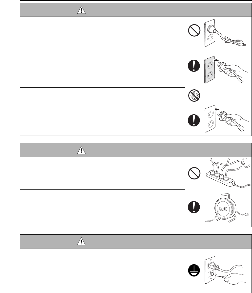
SAFETY AND IMPORTANT WARNING ITEMS
S-4
• Do not bundle or tie the power cord.
Overheating may occur there, leading to a risk of fire.
• Check whether dust is collected around the power plug and wall outlet.
Using the power plug and wall outlet without removing dust may result in
fire.
• Do not insert the power plug into the wall outlet with a wet hand.
The risk of electric shock exists.
• When unplugging the power cord, grasp the plug, not the cable.
The cable may be broken, leading to a risk of fire and electric shock.
WARNING: Wiring
• Never use multi-plug adapters to plug multiple power cords in the same out-
let.
If used, the risk of fire exists.
• When an extension cord is required, use a specified one.
Current that can flow in the extension cord is limited, so using a too long
extension cord may result in fire.
Do not use an extension cable reel with the cable taken up. Fire may
result.
WARNING: Ground Lead
• Check whether the copier is grounded properly.
If current leakage occurs in an ungrounded copier, you may suffer electric
shock while operating the copier. Connect the ground lead to one of the
following points:
a. Ground terminal of wall outlet
b. Ground terminal for which Class D work has been done
WARNING: Power Plug and Cord
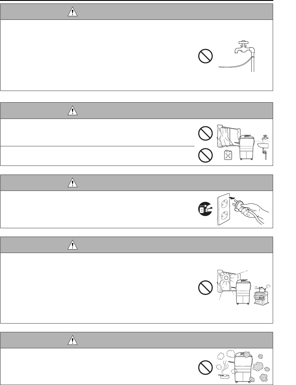
SAFETY AND IMPORTANT WARNING ITEMS
S-5
2.Installation Requirements
• Pay attention to the point to which the ground lead is connected.
Connecting the ground lead to an improper point such as the points listed
below results in a risk of explosion and electric shock:
a. Gas pipe (A risk of explosion or fire exists.)
b. Lightning rod (A risk of electric shock or fire exists.)
c. Telephone line ground (A risk of electric shock or fire exists in the case
of lightning.)
d. Water pipe or faucet (It may include a plastic portion.)
WARNING: Prohibited Installation Place
• Do not place the copier near flammable materials such as curtains or volatile
materials that may catch fire.
A risk of fire exists.
• Do not place the copier in a place exposed to water such as rain water.
A risk of fire and electric shock exists.
WARNING: Nonoperational Handling
• When the copier is not used over an extended period of time (holidays, etc.),
switch it off and unplug the power cord.
Dust collected around the power plug and outlet may cause fire.
CAUTION: Temperature and Humidity
• Do not place the copier in a place exposed to direct sunlight or near a heat
source such as a heater.
A risk of degradation in copier performance or deformation exists.
Do not place the copier in a place exposed to cool wind.
Recommended temperature and humidity are as follows:
Temperature: 10°C to 30°C
Humidity: 10% to 80% (no dew condensation)
Avoid other environments as much as possible.
CAUTION: Ventilation
• Do not place the copier in a place where there is much dust, cigarette
smoke, or ammonia gas.
Place the copier in a well ventilated place to prevent machine problems
and image faults.
WARNING: Ground Lead

SAFETY AND IMPORTANT WARNING ITEMS
S-6
3
• The copier generates ozone gas during operation, but it is not sufficient to be
harmful to the human body.
If a bad smell of ozone is present in the following cases, ventilate the
room.
a. When the copier is used in a poorly ventilated room
b. When taking a lot of copies
c. When using multiple copiers at the same time
CAUTION: Vibration
• When installing the copier, read the Installation Guide thoroughly. Be sure to
install the copier in a level and sturdy place.
Constant vibration will cause problems.
• Be sure to lock the caster stoppers.
In the case of an earthquake and so on, the copier may slide, leading to a
injury.
CAUTION: Inspection before Servicing
• Before conducting an inspection, read all relevant documentation (service
manual, technical notices, etc.) and proceed with the inspection following the
prescribed procedure in safety clothes, using only the prescribed tools. Do
not make any adjustment not described in the documentation.
If the prescribed procedure or tool is not used, the copier may break and a
risk of injury or fire exists.
• Before conducting an inspection, be sure to disconnect the power plugs from
the copier and options.
When the power plug is inserted in the wall outlet, some units are still pow-
ered even if the POWER switch is turned OFF. A risk of electric shock
exists.
• The area around the fixing unit is hot.
You may get burnt.
DANGER: Work Performed with the Copier Powered
• Take every care when making adjustments or performing an operation check
with the copier powered.
If you make adjustments or perform an operation check with the external
cover detached, you may touch live or high-voltage parts or you may be
caught in moving gears or the timing belt, leading to a risk of injury.
CAUTION: Ventilation

SAFETY AND IMPORTANT WARNING ITEMS
S-7
• Take every care when servicing with the external cover detached.
High-voltage exists around the drum unit. A risk of electric shock exists.
WARNING: Safety Checkpoints
• Check the exterior and frame for edges, burrs, and other damages.
The user or CE may be injured.
• Do not allow any metal parts such as clips, staples, and screws to fall into the
copier.
They can short internal circuits and cause electric shock or fire.
• Check wiring for squeezing and any other damage.
Current can leak, leading to a risk of electric shock or fire.
• When disconnecting connectors, grasp the connector, not the cable.
(Specifically, connectors of the AC line and high-voltage parts)
Current can leak, leading to a risk of electric shock or fire.
• Carefully remove all toner remnants and dust from electrical parts and elec-
trode units such as a charging corona unit.
Current can leak, leading to a risk of copier trouble or fire.
• Check high-voltage cables and sheaths for any damage.
Current can leak, leading to a risk of electric shock or fire.
• Check electrode units such as a charging corona unit for deterioration and
sign of leakage.
Current can leak, leading to a risk of trouble or fire.
• Before disassembling or adjusting the write unit incorporating a laser, make
sure that the power cord has been disconnected.
The laser light can enter your eye, leading to a risk of loss of eyesight.
• Do not remove the cover of the write unit. Do not supply power with the write
unit shifted from the specified mounting position.
The laser light can enter your eye, leading to a risk of loss of eyesight.
• When replacing a lithium battery, replace it with a new lithium battery speci-
fied in the Parts Guide Manual. Dispose of the used lithium battery using the
method specified by local authority.
Improper replacement can cause explosion.
DANGER: Work Performed with the Copier Powered

SAFETY AND IMPORTANT WARNING ITEMS
S-8
WARNING: Safety Checkpoints
• After replacing a part to which AC voltage is applied (e.g., optical lamp and
fixing lamp), be sure to check the installation state.
A risk of fire exists.
• Check the interlock switch and actuator for loosening and check whether the
interlock functions properly.
If the interlock does not function, you may receive an electric shock or be
injured when you insert your hand in the copier (e.g., for clearing paper
jam).
• Make sure the wiring cannot come into contact with sharp edges, burrs, or
other pointed parts.
Current can leak, leading to a risk of electric shock or fire.
• Make sure that all screws, components, wiring, connectors, etc. that were
removed for safety check and maintenance have been reinstalled in the orig-
inal location. (Pay special attention to forgotten connectors, pinched cables,
forgotten screws, etc.)
A risk of copier trouble, electric shock, and fire exists.
DANGER: HANDLING OF SERVICE MATERIALS
• Toner and developer are not harmful substances, but care must be taken not
to breathe excessive amounts or let the substances come into contact with
eyes, etc. It may be stimulative.
If the substances get in the eye, rinse with plenty of water immediately.
When symptoms are noticeable, consult a physician.
• Never throw the used cartridge and toner into fire.
You may be burned due to dust explosion.

SAFETY AND IMPORTANT WARNING ITEMS
S-9
1
[3] MEASURES TO TAKE IN CASE OF AN ACCIDENT
1. If an accident has occurred, the distributor who has been notified first must immediately take emergency
measures to provide relief to affected persons and to prevent further damage.
2. If a report of a serious accident has been received from a customer, an on-site evaluation must be carried
out quickly and KMBT must be notified.
3. To determine the cause of the accident, conditions and materials must be recorded through direct on-site
checks, in accordance with instructions issued by KMBT.
4. For reports and measures concerning serious accidents, follow the regulations given in “Serious Accident
Report/Follow-up Procedures”.
[4] CONCLUSION
1. Safety of users and customer engineers depends highly on accurate maintenance and administration.
Therefore, safety can be maintained by the appropriate daily service work conducted by the customer
engineer.
2. When performing service, each copier on the site must be tested for safety. The customer engineer must
verify the safety of parts and ensure appropriate management of the equipment.
DANGER : HANDLING OF SERVICE MATERIALS
• Unplug the power cord from the wall outlet.
Drum cleaner (isopropyl alcohol) and roller cleaner (acetone-based) are
highly flammable and must be handled with care. A risk of fire exists.
• Do not replace the cover or turn the copier ON before any solvent remnants
on the cleaned parts have fully evaporated.
A risk of fire exists.
• Use only a small amount of cleaner at a time and take care not to spill any
liquid. If this happens, immediately wipe it off.
A risk of fire exists.
• When using any solvent, ventilate the room well.
Breathing large quantities of organic solvents can lead to discomfort.

SAFETY AND IMPORTANT WARNING ITEMS
S-10
The Center for Devices and Radiological Health (CDRH) of the U.S. Food and Drug Administration implemented
regulations for laser products manufactured since August 1, 1976. Compliance is mandatory for products mar-
keted in the United States.
This copier is certified as a “Class 1” laser product under the U.S.
Department of Health and Human Services (DHHS) Radiation Performance Standard according to the Radiation
Control for Health and Safety Act of 1968. Since radiation emitted inside this copier is completely confined within
protective housings and external covers, the laser beam cannot escape during any phase of normal user opera-
tion.
SAFETY INFORMATION
IMPORTANT INFORMATION

SAFETY AND IMPORTANT WARNING ITEMS
S-11
This machine is provided with the following safety cir-
cuits to prevent machine faults from resulting in seri-
ous accidents.
[1] Overall protection circuit
[2] L2 and L3 (fixing heater lamp/1, /2) overheat-
ing prevention circuit
These safety circuits are described below to provide
the service engineer with a renewed awareness of
them in order to prevent servicing errors that may
impair their functions.
[1] Overall protection circuit
1. Protection by CBR1 and CBR2 (circuit
breaker/1, /2)
CBR1 and CBR2 interrupt the AC line instanta-
neously when an excessive current flows due
to a short in the AC line.
CAUTION:
The CBR1 and CBR2 functions must not
be deactivated under any circumstances.
[2] L2 and L3 (fixing heater lamp/1, /2)
overheating prevention circuit
1. Protection by software
The output voltage from TH1, TH2 (fixing tem-
perature sensor/1, /2) is read by the CPU. If
this voltage is abnormal, L2 (fixing heater
lamp/1), L3 (fixing heater lamp/2) and RL1
(main relay) are turned OFF.
CAUTION:
The RL1 function must not be deactivated
under any circumstances.
SAFETY CIRCUITS
DCPS
CBR1
CBR2
DCPS
CB
L3
L2
AC driver
section
RL1
FCB
Control
section
TH1 TH2
RL1 TS

SAFETY AND IMPORTANT WARNING ITEMS
S-12
3
2. Protection by the hardware circuit
The output voltages from TH1, TH2 (fixing tem-
perature sensor/1, /2) are compared with the
abnormality judgment reference value in the
comparator circuit. If the output voltage from
TH1 or TH2 exceeds the reference value, L2
(fixing heater lamp/1), L3 (fixing heater lamp/2)
and RL1 (main relay) are turned OFF in hard-
ware means.
CAUTION:
Periodically check the TH1, TH2 face
contacting the roller, and replace TH2 if
any abnormality is detected.
The RL1 function must not be deactivated
under any circumstances.
3. Protection by TS (thermostat)
When the fixing heat roller exceeds the speci-
fied value, TSs (thermostats) are turned OFF,
thus interrupting the power to L2 (fixing heater
lamp/1), and L3 (fixing heater lamp/2) directly.
CAUTION:
Do not use any other electrical conductor
in place of TS1 and TS2.

SAFETY AND IMPORTANT WARNING ITEMS
S-13 3
Caution labels shown below are attached in some areas on/in the machine.
When accessing these areas for maintenance, repair, or adjustment, special care should be taken to avoid burns
and electric shock.
[1] Main body
1. Right side
<7145>
CAUTION
INDICATION OF WARNING ON THE MACHINE
You may be burned or injured if you touch any area that you are advised by any caution label to keep your-
self away from.
Do not remove caution labels. If any caution label has come off or soiled and therefore the caution cannot
be read, contact our Service Office.
7322sf001e
CAUTION
The fixing unit is very hot.
To avoid getting burned
DO NOT TOUCH.
CAUTION
This area generates
high voltage.
If touched, electrical
shock may occur.
DO NOT TOUCH! CAUTION
The roller shaft on the inside
of the cover is very hot.
To avoid getting burned DO
NOT TOUCH.
If the cover comes off, return
it to its original position.
(Inside of the main
body right side door)
(Inside of the main
body front door)

SAFETY AND IMPORTANT WARNING ITEMS
S-14
3
<7235/7228/7222>
CAUTION
You may be burned or injured if you touch any area that you are advised by any caution label to keep your-
self away from.
Do not remove caution labels. If any caution label has come off or soiled and therefore the caution cannot
be read, contact our Service Office.
7322sf002e
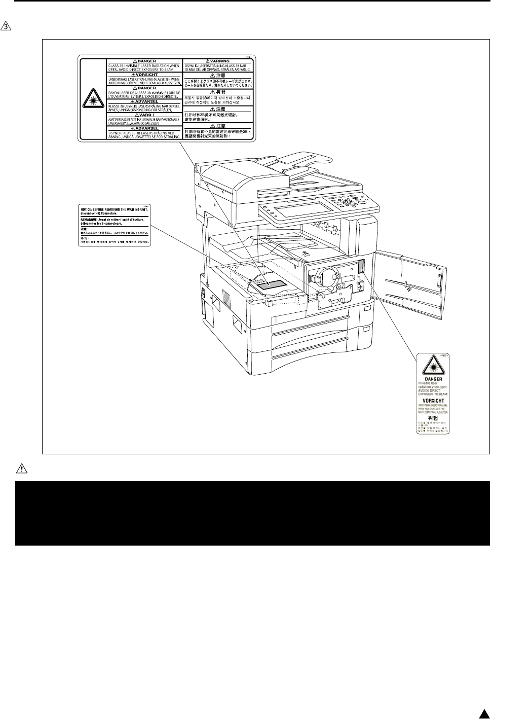
SAFETY AND IMPORTANT WARNING ITEMS
S-15 3
2. Front side
<7145>
CAUTION
You may be burned or injured if you touch any area that you are advised by any caution label to keep your-
self away from.
Do not remove caution labels. If any caution label has come off or soiled and therefore the caution cannot
be read, contact our Service Office.
7322sf003e

SAFETY AND IMPORTANT WARNING ITEMS
S-16
3
<7235/7228/7222>
CAUTION
You may be burned or injured if you touch any area that you are advised by any caution label to keep your-
self away from.
Do not remove caution labels. If any caution label has come off or soiled and therefore the caution cannot
be read, contact our Service Office.
7322sf004e

SAFETY AND IMPORTANT WARNING ITEMS
S-17 3
3. Rear/Left side (7235/7228/7222 only)
CAUTION
You may be burned or injured if you touch any area that you are advised by any caution label to keep your-
self away from.
Do not remove caution labels. If any caution label has come off or soiled and therefore the caution cannot
be read, contact our Service Office.
7322sf005e
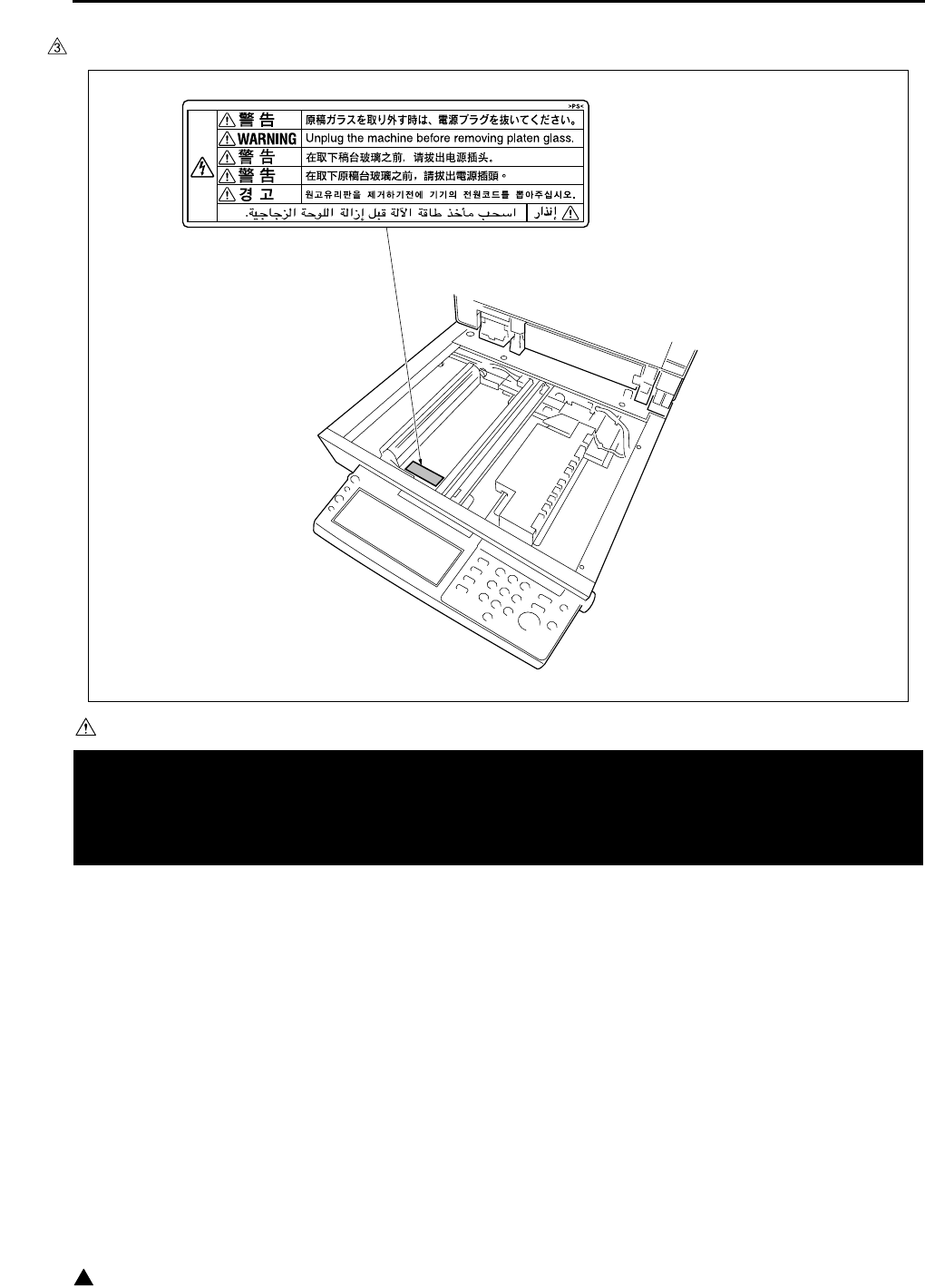
SAFETY AND IMPORTANT WARNING ITEMS
S-18
3
4. Scanner section
<7145>
CAUTION
You may be burned or injured if you touch any area that you are advised by any caution label to keep your-
self away from.
Do not remove caution labels. If any caution label has come off or soiled and therefore the caution cannot
be read, contact our Service Office.
7322sf006

SAFETY AND IMPORTANT WARNING ITEMS
S-19 3
<7235/7228/7222>
CAUTION
You may be burned or injured if you touch any area that you are advised by any caution label to keep your-
self away from.
Do not remove caution labels. If any caution label has come off or soiled and therefore the caution cannot
be read, contact our Service Office.
7322sf007e
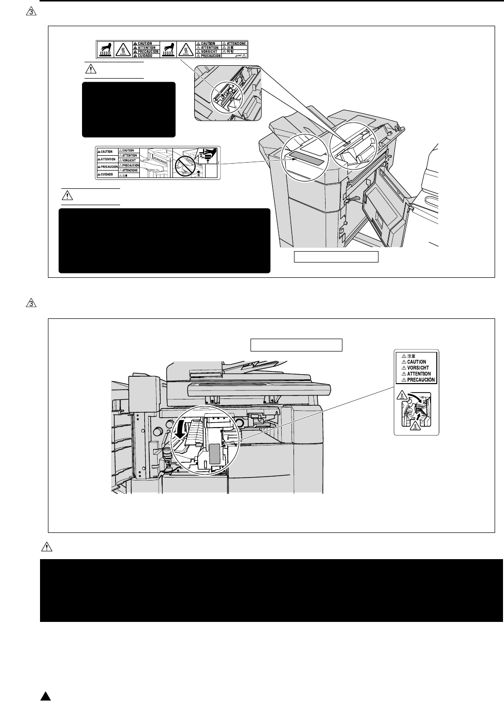
SAFETY AND IMPORTANT WARNING ITEMS
S-20
3
[2] FS-113
[3] FS-114
CAUTION
You may be burned or injured if you touch any area that you are advised by any caution label to keep your-
self away from.
Do not remove caution labels. If any caution label has come off or soiled and therefore the caution cannot
be read, contact our Service Office.
7322sf009
CAUTION
This area is very hot.
To avoid getting
burned DO NOT
TOUCH.
CAUTION
To avoid injury, DO NOT put your hand on the top
of the printed sheets. Be sure to hold both sides
of the printed sheets when removing them, and
DO NOT leave your hand on the printed sheets
while the primary (main) tray goes up.
(Inside of the Finisher)
FS-113 Finisher
7322sf010
FS-114 Finisher

I ADJUSTMENT
HOW TO USE THE ADJUSTMENT SECTION
1-1
IADJUSTMENT
1. HOW TO USE THE
ADJUSTMENT SECTION
1.1 Composition
This section details adjusting items and procedures.
A. Checking before starting work
Use this section for making adjustments and as
a checklist before implementing corrective
measures in the field.
1. Does the power supply meet the requirements?
2. Is the power supply properly grounded?
3. Is the machine sharing its power source with
another high current consumption machine that
draws large currents intermittently? (e.g. an ele-
vator, air conditioner, or other source of electri-
cal consumption)
4. Is the installation environment suitable?
• The machine must be installed in a wellventi-
lated place free from high temperature, high
humidity and direct sunlight.
• The machine must be installed on a level
floor.
5. Does the cause of a defective image lie in the
original itself?
6. Is the density adjusting control at the proper
position?
7. Are the platen glass and the slit glass clean?
8. Is the correct paper being used for the copy?
9. Are the copying materials and parts replaced
when they reach the end of their usable life?
(developer, drum, cleaning blade, etc.)
10. Is there toner in the toner bottle?
B. Checkpoints when conducting on-site ser-
vice
Be sure to pay due attention to the following
when repairing the machine.
1. Only one side of the AC power line is discon-
nected when the main power of this machine is
turned off. Always unplug the machine before
beginning work. If absolutely necessary to work
with the power on, exercise care to avoid being
caught in the scanning rear of the exposure unit.
2. Special care should be taken when handling the
fixing unit since it operates at extremely high
temperatures.
3. The developing unit is surrounded by a strong
magnetic field. Keep watches and metering
equipment away from it.
4. Avoid scarring the drum with tools or similar
objects.
5. Do not touch IC pins with your bare hands.
2. ADJUSTMENTS WHEN
REPLACING PARTS
Adjustments (including checks) and settings are not
only required when a defective copy image occurs,
but also after replacing or reinstalling certain parts.
[How to use the tables]
The following items are used in the tables through-
out this section.
1. Mode
Indicates the adjustment mode.
“25” : 25 mode
“36” : 36 mode
“47” : 47 mode
2. Symbols used in the tables
, ................. : Indicates there is a pri-
ority sequence for
adjustments (including
checks) and settings.
{ (Empty circle) : Indicates adjustments
(including checks) and
settings that can be car-
ried out independently.
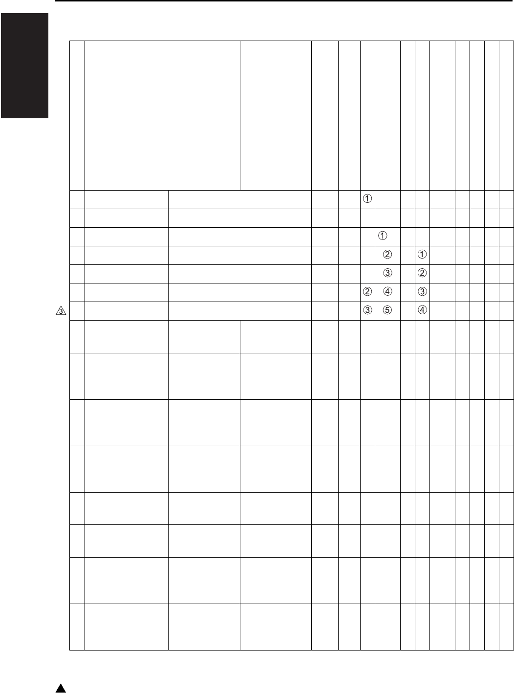
I ADJUSTMENT
LIST OF ADJUSTMENT ITEMS
1-2
3
3. LIST OF ADJUSTMENT ITEMS
Adjustment classification Adjustment
items
Mode
Page
Drum
Developer
Fixing unit-related parts
Write unit
Parameter memory board
Paper feeding-related rubber rollers
RADF
RADF slit glass
E-RDH
1 PM counter resetting 25 1-30 {{
2 PM cycle set 25 1-30 {
3
Process adjustment
L detection adjustment 36 1-46 *1{*2
4
Process adjustment
Toner density adjustment 36 1-46 {
5
Process adjustment
Dot diameter adjustment 36 1-47 {
6
Process adjustment
LD1 offset adjustment 36 1-47 {
7
Process adjustment
LD2 offset adjustment (7145) 36 1-48 {
8 Image adjustment Magnification
adjustment
Vertical magnifi-
cation of printer 36 1-49 {{{
9 Image adjustment Magnification
adjustment
Vertical magnifi-
cation of scan-
ner (platen)
36 1-51 {{{
10 Image adjustment Magnification
adjustment
Vertical magnifi-
cation of scan-
ner (RADF)
36 1-52 {{ {
11 Image adjustment Magnification
adjustment
Horizontal mag-
nification of
scanner
36 1-51 {{
12 Image adjustment Timing adjust-
ment
Main body
related 36 1-52 {{{
13 Image adjustment Timing adjust-
ment
RADF 36 1-53 {{ {
14 Image adjustment Timing adjust-
ment
Paper feed loop
amount adjust-
ment
36 1-54 {
15 Image adjustment Timing adjust-
ment
Leading edge
original erasure
adjustment
36 1-55 {{

I ADJUSTMENT
LIST OF ADJUSTMENT ITEMS
1-3 3
16 Image adjustment Timing
adjustment
Image read point
adjustment 36 1-58 {{
17 Image adjustment Centering
adjustment
Main body related
Centering
adjustment
36 1-56 {{
18 Image adjustment Centering
adjustment
DBLT centering
adjustment 36 1-56 {{
19 Image adjustment Centering
adjustment
RADF centering
adjustment 36 1-58 {{ {
20 Image adjustment RADF
adjustment
RADF scanner
density
adjustment
36 1-65 {{{
21
Drum count resetting
Drum count resetting 25/36 1-40 {
22 Fixing unit related
counter resetting
Fixing unit related
counter resetting 25/36 1-68 {
23 E-RDH memory
check
E-RDH memory check 47 1-88 {
*1 After replacing the developer, be sure that you do not make any copies until you have first carried out L
detection adjustment.
*2 When PRMB (Parameter memory board) is replaced, remember to replaced the developer before con-
ducting the L deection adjustment.
Note:
• When replacing a board due to the SCB (System control board) being damaged, the PRMB (Parameter
memory board) that was installed on the damaged SCB should be used as a rule on the new SCB.
The use of a new PRMB should be limited only when it is considered that the PRMB is also damaged.
On this occasion, adjustment data have not been input into the new PRMB and it is necessary to imple-
ment all of the adjustment items. In order to make the new PRMB effective, the 47 mode - 92 (output)
should be carried out before implementation of the adjustment items.
• When the adjustment items have been implemented, the 47 mode - 96 (output) should be also executed.
The adjustment data are backed up by implementing the 47-96 mode.
For the original PRMB installed on the damaged SCB, the 47-92 mode is protected against inadvertent
execution. For details of the cancellation of protection, contact the service manager of the authorized dis-
tributor.
Adjustment classification Adjustment
items
Mode
Page
Drum
Developer
Fixing unit-related parts
Write unit
Parameter memory board
Paper feeding-related rubber rollers
RADF
RADF slit glass
E-RDH

2
I ADJUSTMENT
CE PASSWORD SETTING
1-4
4. CE PASSWORD SETTING
Important:
• In order to prevent the malicious CE to access
data and to change settings of the machine,
ensure to change the CE password.
On key operator mode, if the enhanced security is
enabled, CE password must be input to verify the
CE to access the following service modes.
“36 mode”
“25 mode”
“47 mode”
Register a CE password by the following procedure.
A. Procedure
1. While the SW1 (main power switch) is ON, turn
OFF SW2 (sub power switch)
2. Turn the SW2 ON while pressing 2 and 5 of the
copy quantity setting buttons
CE password input request screen appears.
3. Enter default password “92729272”.
On the LCD, basic screen for 25 mode
appears.
4. Press [5. Password setting] key.
Password setup screen appears.
5. Press [4. CE Password setting] key.
CE password input screen appears.
6. Enter new 8-digit CE password then press [Set]
key.
7. OFF/ON sub-switch to complete password input
procedure and to exit from 25 mode.
Note:
• Only alphanumerical keys can be used for the
password. Continuous single alphanumeric can-
not be used for the password.
• In order to change the registered password, in the
above step 3, enter current password and con-
tinue following steps.
• Do not use name, your birthday or employee
code number as the password since other people
can easily guess them.
• CE should not inform other people of the pass-
word.
5. MODE CHANGE MENU
5.1 Setting Method
The following modes can be selected on the mode
change menu screen without turning OFF/ON the
power supply:
“1 Basic screen”
“2 36 mode”
“3 25 mode”
“4 Key operation mode”
“5 47 mode”
“6 Exit”
A. Procedure
1. Turn on SW1 (main power switch) and SW2
(sub power switch).
2. Keep pressing the ∗ button until the message
“Enter password for mode selection” appears.
3. Input 9272 as the password and press the
[START] key. (The password is fixed and cannot
be changed.)
4. Press the key of the mode to be selected on the
screen.
If enhanced security is enabled, enter CE pass-
word to access to “25 mode”, “36 mode” and
“47 mode”. Enter Key operator password to
access [Key operator mode].
5. To return to the “Mode Change Menu screen”,
keep pressing the ∗ button until the “Mode
Change Menu screen” appears.
6. When the adjustment ends, press [6. Exit] key
and the basic screen will appear.

I ADJUSTMENT
CHECKING BY THE COUNTER KEY FUNCTION
1-5
6. CHECKING BY THE
COUNTER KEY FUNCTION
The counter key function enables to display of the
following parameters by using the counter button:
“1 Total count”
“2 Total count start date”
“3 PM count/PM count limit”
“4 PM count start date”
“5 Fax send paper count”
“6 Fax receive paper count”
“7 Printer count”
“8 Scanner count”
“9 Drum count”
“10 Developing count”
“11 Fixing unit count”
6.1 Checking Method of the
Counter Key Function
A. Procedure
1. Turn on SW1 (main power switch) and SW2
(sub power switch).
2. Press the counter button.
3. The “Counter confirmation screen” appears, and
the total count value appears. The counter that
appears differs depending upon the installed
option.
4. If you press the ! button on the “Counter confir-
mation screen”, service-related counters that
indicate the PM count, and so on, appear.
5. To output the count value list, press the [PRINT]
key.
6. Press the [OK] key or the stop button to return to
the basic screen.
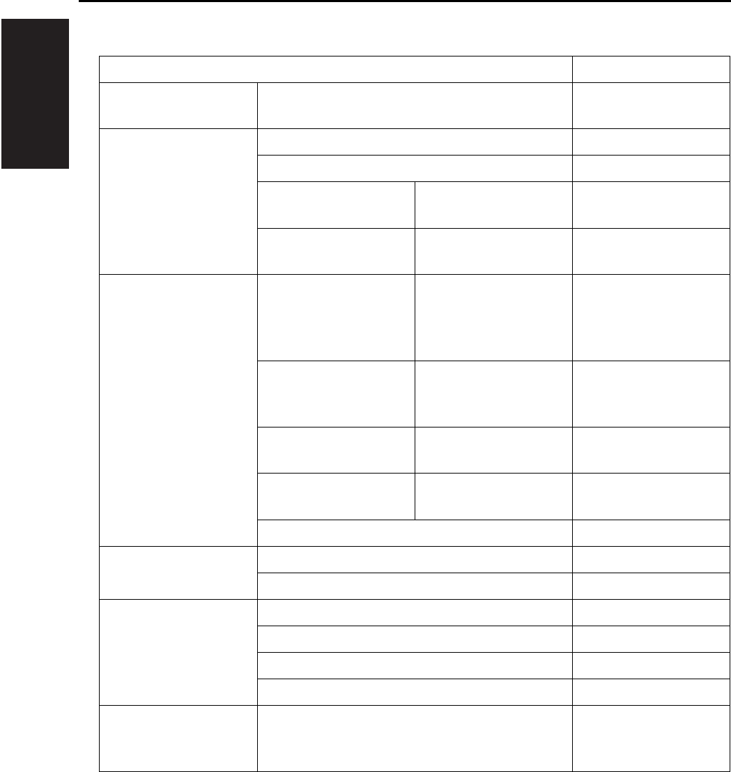
I ADJUSTMENT
25 MODE
1-6
7. 25 MODE
Adjustment item menu Remarks
1. Software DIPSW
setting
See the “List of soft-
ware DIPSW”.
2. PM COUNT/CYCLE
1. PM COUNT reset
2. PM CYCLE set
3. Counter clear 1. Drum related
counter
3. Counter clear 2. Fixing related
counter
3. Collecting data 1. Count data
collection
Data Collection 1
Copy count of each
paper size
RADF paper passage count
1. Count data
collection
Data Collection 2
JAM occurrence
count by each point
1. Count data
collection
Data Collection 3
Copy count of each mode
1. Count data
collection
Data Collection 4
SC count : F code
2. Periodic data collection starts
4. Parts counter 1. Count of parts (Fixed)
2. Count of parts (Named)
5. Password setting 1. Key operator password setting 8 digits
2. User account (EKC) master key code setting 8 digits
3. Weekly timer master key code setting 4 digits
4. CE password setting 8 digits
6. Service TEL No.
setting
Telephone & Fax. No.
of service center set-
ting.

I ADJUSTMENT
25 MODE
1-7 3
.
7. Serial number
setting
1. Main body Sets up the serial
number display and
the destination.
2. Optional tray
3. LCT
4. Finisher
5. Fax
6. Printer
7. FL-102/FL-103
8. FS-114 punch unit
9. FS-114 saddle unit
10.RADF (7235/7228/7222)
8. Indication of ROM
version
Display each version
of ROM.
9. KRDS setting See the KRDS man-
ual provided sepa-
rately.
10. ISW Rewrites the con-
tents of the flash
ROM of each board.
11. Indication of Root
counter
Displays the root coun-
ter (total counter).
12. Setting date Sets the starting date
of the total counter.
13. Tray size setting Set the paper size of
LT-203.
Adjustment item menu Remarks
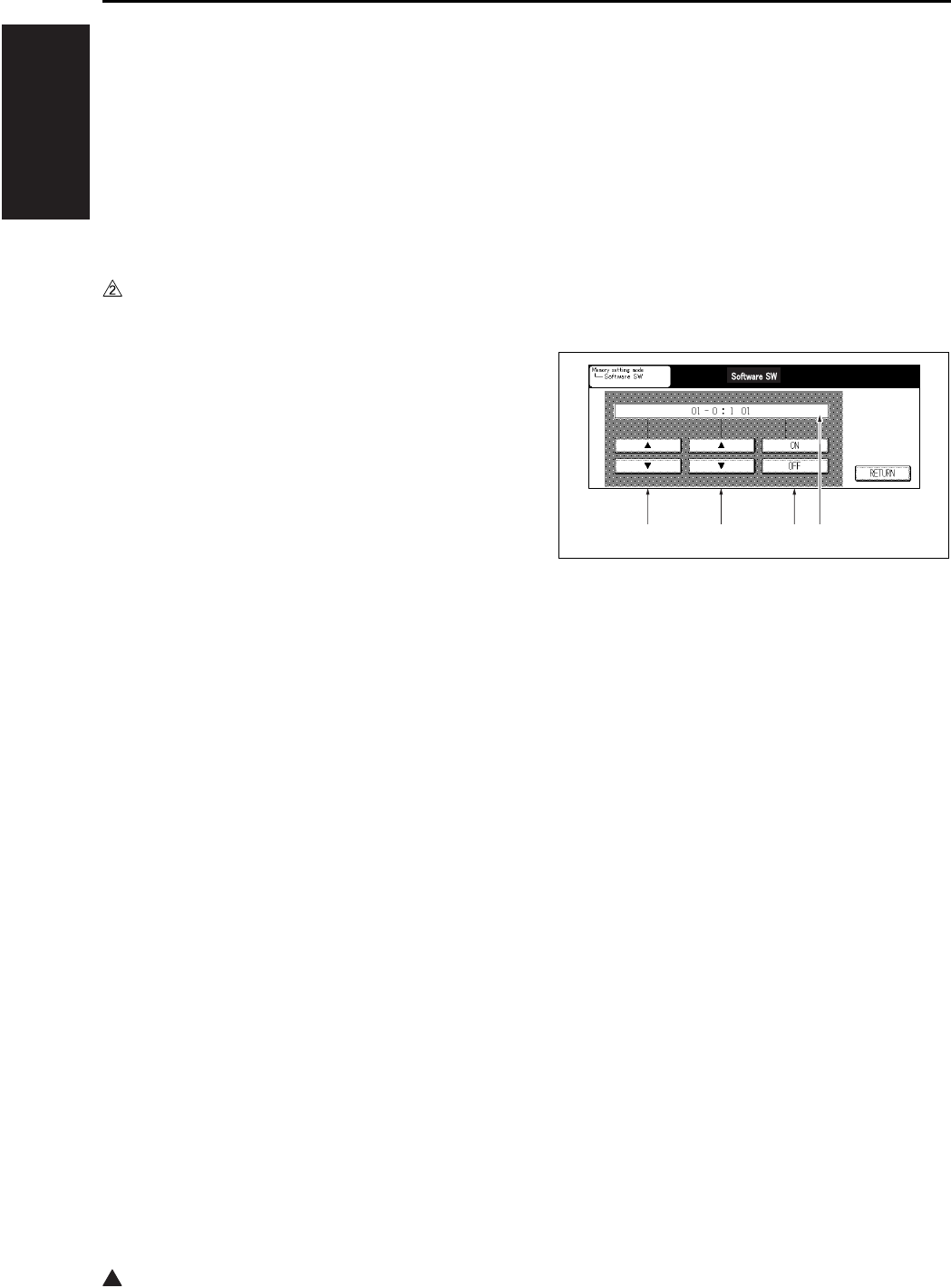
2
I ADJUSTMENT
25 MODE
1-8
7.1 Setting Method
A special operating mode called “25 Mode” has
been provided with this machine. This mode
enables rewriting of the non-volatile storage and
specify other various settings.
A. Procedure
1. Turn OFF the SW2 (sub power switch) when the
SW1 (main power switch) remains ON.
2. Turn the SW2 ON while pressing 2 and 5 of the
copy quantity setting buttons.
If enhanced security is enabled, CE password
input request screen appears. Input the CE
password.
25 mode menu screen appears. At this moment,
the machine turns to 25 mode and the normal
copy operation is disabled.
3. Press the desired item key on the LCD screen.
Each setting screen will appear.
4. Enter data in each selected screen.
5. Press the [RETURN] key to check the data that
has been entered.
6. Turn the SW2 off to cancel the 25 mode.
7. New data will be effective after restarting.
7.2 Setting Software DIPSW
A. Setting method
This setting specifies the software DIPSW on
the software SW setting screen.
Note:
• The bit of the DIP switch is written in the non-vol-
atile memory every time it is changed.
B. Meaning of the values displayed on the
screen
C. Procedure
1. Enter the 25 Mode.
2. “25 mode menu screen”
Press the [Software SW] key.
3. “Software setting screen”
Select DIP switch number.
Use the arrow key on the left.
4. Select bit number of the DIP switch.
Use the arrow key at the center.
5. Select ON (=1) or OFF (=0) of the DIP switch.
Use [ON] or [OFF] key.
[ON] : Set bit.
[OFF] : Clear bit.
6. Press the [RETURN] key to return to the “25
mode menu screen”.
• For each switch function, see “List of software
DIPSW”.
[1] DIPSW number
[2] Bit number (0 to 7)
[3] Bit data : 1:ON, 0:OFF
[4] 8-bit switch values in indicated in hexadec-
imals from 00 to FF.
[1] [2] [3] [4]

I ADJUSTMENT
25 MODE
1-9 3
List of software DIP SW
Note:
• Be sure not to change bits with no particular reference made of the function.
DIPSW No. Bit Functions 0 1 Default values
Japan Inch Metric
DIPSW1 0 Operation when key counter
is removed
Ignore Instantaneous
stop Jam
011
1 A3 (11 x 17) counting
method
Count as 1 Count as 2 0 0 0
2— ——000
3 Selection of maximum num-
ber of copies that can be sta-
pled by FS-112/113
*1*1000
4000
5— ——000
6— ——000
7 FS-112/114 limit on number
of stapled sets
None *000
DIPSW2 0 Toner replenish stop timing 1 Decide with
DIPSW 3-2
Stop after paper
exited
000
1— ——000
2— ——111
3— ——111
4— ——000
5
1-shot message display at auto-
matic staple mode clearing
Yes No 1 1 1
6— ——111
7 Prohibition of non-image
area erases, repeat (auto)
and original position correc-
tion
No Yes 0 0 0
DIPSW3 0 Use F4 size for Latin Amer-
ica destination
No Yes 0 0 0
1 SC latch (F34/F35/F36) Unlatched Latched 0 0 0
2 Toner replenish stop timing 2 When copying
ends
Interval between
copy set
000
* FS-112: Message is displayed after stopping temporarily at 25 copies.
FS-114: Message is displayed after stopping temporarily at 20 copies.

I ADJUSTMENT
25 MODE
1-10
3
DIPSW3 3 Return to EKC screen after
copying reservation
No Yes 0 0 0
4— ——111
5— ——000
6— ——000
7— ——000
DIPSW4 0 Toner level detection
(“Supply toner” indication)
*2*2000
1000
2 Condition for stopping copy-
ing after toner supply display
*3*3111
3111
4 Non-display of advance/
delete buttons for job list
Yes No 0 0 0
5 Job stop when there is no
toner left.
No Yes 1 1 1
6
Copy reservation allowed (cor-
responding to coin vendor)
Can reserve
copying
Cannot reverse
copying
000
7— ——000
DIPSW5 0 — — — 0 1 0
1— ——001
2— ——000
3— ——000
4— ——000
5 Toner consumption reduction
SW
*5*5000
6000
7— ——000
DIPSW6 0 — — — 0 0 0
1 K size selection SW for Tai-
wan destination
Metric sizes K sizes
available
000
2
K size selection SW for Taiwan
destination (By pass feed)
Metric sizes K sizes
available
000
3— ——000
DIPSW No. Bit Functions 0 1 Default values
Japan Inch Metric

I ADJUSTMENT
25 MODE
1-11
DIPSW6 4
Timing for the polygon motor to
stop/start to rotate at low speed
*6*6000
5111
6 Setting for the polygon motor
to stop/rotate at low speed
*7*7111
7000
DIPSW7 0 Selection of automatic era-
sure outside original
*8*8111
1 Automatic restart after feed-
ing paper (Other than Inch)
*9*9000
2 Automatic conversion of
paper size detected by APS
(8.5 x 11/A4)
*10 *10 1 0 0
3 Nonstandard-size notifica-
tion for platen APS A4
(Japan, Metric)/8.5x11 (Inch)
*11 *11 0 0 0
4 Nonstandard-size notifica-
tion for platen APS B6
(Japan)/A5 (Metric)/5.5 x 8.5
(Inch)
*11 *11 0 0 0
5 Password that requires 25/
36/47 mode (9272)
Not required Required 0 0 0
6 Selection of A series size
(Metric only)
No Yes 0 0 0
7— ——000
DIPSW8 0 — — — 1 0 0
1 Changing of key operator
fixed magnification setting
Permit Prohibit 1 0 0
2 Disabling copying when PM
count reached
Permit Prohibit 0 0 0
3— ——000
4 Priority tray when APS is
released
*12 *12 0 0 0
5000
6000
7 For checking the collected
data 2 to 4 in the 25 mode
Display
restricted
Display not
restricted
000
DIPSW No. Bit Functions 0 1 Default values
Japan Inch Metric

I ADJUSTMENT
25 MODE
1-12
DIPSW9 0 Selection of copy quantity
limit
*13 *13 0 0 0
1000
2000
3000
4— ——000
5— ——000
6 Switching of message *14 *14 0 0 0
7000
DIPSW10 0 Setting for summer time *15 *15 0 0 0
1111
2111
3000
4 Selection of magnification
mode when APS function is
cancelled
Display auto 1.00 0 0 0
5— ——000
6 Icon display in the LCD mes-
sage display section (toner
shortage, PM)
No Yes 1 0 0
7 Displaying of JAM code No Yes 0 0 0
DIPSW11 0 Release of the applied func-
tion when the RADF is open
No Yes 0 0 0
1— ——000
2— ——000
3— ——000
4— ——000
5— ——000
6— ——000
7— ——000
DIPSW No. Bit Functions 0 1 Default values
Japan Inch Metric

I ADJUSTMENT
25 MODE
1-13
DIPSW12 0 — — — 0 0 0
1— ——000
2— ——000
3 Setting of PM count at which
copying is inhibited
*16 *16 0 0 0
4000
5000
6 KRDS connection recogni-
tion
Not recognize Recognize 0 0 0
7
F/E code screen switchover
(except for F34, F35 and F36)
No Switched
(all in F code)
000
DIPSW13 0 — — — 0 0 0
1— ——000
2— ——000
3 Selection of filter for jagged
edges on slanting lines
ON OFF 0 0 0
4— ——000
5— ——000
6 Judging level of the out-of-
original auto erasure mode
*17 *17 1 1 1
7000
DIPSW14 0
Operation when stapling is not
possible (Other than B6R, post
card nonstandard)
*
*18 *18 0 1 0
1010
2— ——010
3— ——010
4 Operation when one position
stapling is not available*
*19 *19 0 0 0
5000
6 Operation when two position
stapling is not available*
*20 *20 0 0 0
7000
* Common to FS-112/113
DIPSW No. Bit Functions 0 1 Default values
Japan Inch Metric

I ADJUSTMENT
25 MODE
1-14
3
DIPSW15 0 — — — 0 0 0
1— ——000
2— ——000
3— ——000
4— ——000
5— ——000
6
Stopping due to overloading
when the FNS is not connected
(when exiting 100 sheets)
Not stop Stop 0 0 0
7
Stopping due to overloading when
the FNS, IT is not connected (when
exiting 400 sheets)
Decided on
DIPSW15-6
Stop 1 1 1
DIPSW16 0 Fixing temperature at low
power mode
*21 *21 0 1 1
1*a0 0
2 Operation of internal heater Always ON Heater off while
in off mode
111
3 Copying before execution of
the L detection
Permit Prohibit 1 1 1
4— ——000
5— ——000
6 Control of dot diameter
adjustment
*22 *22 1 1 1
7*b*b*b
DIPSW17 0 F4 size setting *23 *23 0 0 0
1000
2000
3
HOST printing cannot be performed
when a key counter is installed
Printing takes
place
Printer abort
processing
000
4— ——000
5 Shift from bypass feed in
ATS mode is inhibited
Shift inhibited Shift possible 0 0 0
6— ——000
*a Default value of the 7145 is “0”. Default value of the 7235/7228/7222 is “1”.
*b Default value of the 7145 is “0”. Default value of the 7235/7228/7222 is “1”.
DIPSW No. Bit Functions 0 1 Default values
Japan Inch Metric

I ADJUSTMENT
25 MODE
1-15 3
DIPSW17 7 Separation claw operation
OFF mode (for machines
destined for China)
Normal OFF 0 0 0
DIPSW18 0 Tray 1 (main body upper
stage), separation of defec-
tive part
Normal Not allowed to
use
000
1 Tray 2 (main body lower
stage), separation of defec-
tive part
Normal Not allowed to
use
000
2— ——000
3— ——000
4 Tray 3 (DB upper stage),
separation of defective part
Normal Not allowed to
use
000
5 Tray 4 (DB lower stage),
separation of defective part
Normal Not allowed to
use
000
6 Tray 5 (LT), separation of
defective part
Normal Not allowed to
use
000
7 DB is isolated Normal Not allowed to
use
000
DIPSW19 0 Separation of defective part
of printer controller
Normal Not allowed to
use
000
1 Separation of defective part
of FAX board
Normal Not allowed to
use
000
2— ——000
3 Separation of defective part
of HDD
Normal Not allowed to
use
000
4 Separation of defective part
of ADU
Normal Not allowed to
use
000
5 Separation of defective part
of scanner
Normal Not allowed to
use
000
6— ——000
7 Separation of defective part
of RADF
Normal Not allowed to
use
000
DIPSW No. Bit Functions 0 1 Default values
Japan Inch Metric

I ADJUSTMENT
25 MODE
1-16
3
DIPSW20 0 Separation of defective part
of Network
Normal Not allowed to
use
000
1 Separation of defective part
of IEEE1284
Normal Not allowed to
use
000
2 Separation of defective part
of USB
Normal Not allowed to
use
000
3— ——000
4 Separation of defective part
of FNS
Normal Not allowed to
use (Offset not
allowed to use)*
000
5 Separation of defective part
of the saddle
Normal Not allowed to
use
000
6— ——000
7— ——000
DIPSW21 0 Platen size recognition
selector switch 1 for Latin
America (Inch only)
8.5 x 11 A4 0 0 0
1 Platen size recognition
selector switch 2 for Latin
America (Inch only)
8.5 x 11R A4R 0 0 0
2 Platen size recognition
selector switch 3 for Latin
America (Inch only)
8.5 x 14 F4 0 0 0
3 Notice of nonstandard small
platen size (Inch only)
Notice of
noticed size
Notice as non-
standard size
000
4 Job suspension/end at pull-
ing out key counter
*24 *24 0 0 0
5 Notice of small size of platen
mode (8.5x11/A4 or smaller)
Notice size
detected by
APS
Notice size as
A4 (Japan, Met-
ric) or 8.5x11
(Inch)
010
6 Switching of the count-up
function
*25 *25 0 0 0
7 When using an EKC, the
password screen appears at
the end of each job
No Yes 0 0 0
* The saddle is also detached.
DIPSW No. Bit Functions 0 1 Default values
Japan Inch Metric

I ADJUSTMENT
25 MODE
1-17 3
DIPSW22 0 — — — 1 1 1
1 Nonstandard size becomes
effective at automatic platen
start
*26 *26 0 0 0
2— ——000
3— ——000
4 Indication of total count start
day on counter key mode
screen
No Yes 0 0 0
5— ——000
6— ——000
7— ——111
DIPSW23 0 Automatic changeover to
Tray 1 when FNS tray is full*
No Yes 1 1 1
1 Automatic changeover to
Tray 2 when FNS tray is full*
No Yes 1 1 1
2 Automatic changeover to
Tray 3 when FNS tray is full*
No Yes 1 1 1
3 Automatic changeover to
Tray 4 when FNS tray is full*
No Yes 1 1 1
4 100 sheets are exited when
FNS is not stapled, and tray
is detected full*
No Yes 0 0 0
5 100 sheets are exited when
FNS is stapled, and tray is
detected full*
No Yes 1 1 1
6— ——000
7 Machine stops when fixing
web count reaches to the
limit
No Yes 0 0 0
* FS-112 only (7145)
DIPSW No. Bit Functions 0 1 Default values
Japan Inch Metric

I ADJUSTMENT
25 MODE
1-18
3
DIPSW24 0 — — — 0 0 0
1— ——111
2 Automatic change of printer
paper size
*27 *27 0 0 0
3000
4— ——010
5— ——001
6 Punching of mixed size print
job
Release punch
automatically
Not release punch
and continue
000
7 Job stop changeover without
print process stop
*29 *29 0 0 0
DIPSW25 0 Automatic changeover to
tray 1 when the IT tray is full
No Yes 0 0 0
1 Automatic changeover to
tray 2 when the IT tray is full
No Yes 0 0 0
2— ——000
3 Switching of TSL control Normal on/off All off 0 0 0
4— ——000
5 For postcard-to-postcard
copying, rotation takes place
even when APS/AMS is not
used
No Yes 0 0 0
6 180 degree rotation takes
place even when there are
no staples
No Yes 0 0 0
7 FAX transmission 8K/16K for
machines destined for Tai-
wan
Image is trans-
mitted in
reduced form
Image is trans-
mitted with both
edges erased
000
DIPSW26 0 — — — 0 0 0
1— ——000
2— ——111
3 Image position reference
use for bypass feed copying
on non-standard size paper
Center Rear side of
transfer paper
000
4 Printer EKC mismatch print
operation
Permit Prohibit 0 0 0
5— ——000
DIPSW No. Bit Functions 0 1 Default values
Japan Inch Metric

I ADJUSTMENT
25 MODE
1-19 3
DIPSW26 6
The timer for canceling a job that
was interrupted due to removal
of the key counter is valid
Disabled Enabled 0 0 0
7 Scanner function Yes No 0 0 0
DIPSW27 0 Automatic copying reserva-
tion function
*30 *30 0 0 0
1 Paper exit function with face
up in the double sided copy
mode (corresponding to let-
ter head paper)
Not provided Provided 0 0 0
2 Permission SW for copying
double sided special paper
Permit Prohibit 0 0 0
3— ——000
4 Image rotation control when
using scanner
Only those
smaller than A4/
letter rotate
Those larger
than A4/letter
also rotate
000
5 Density setting when the
printer toner save function is
selected
*31 *31 0 0 0
6000
7000
DIPSW28 0 Leading edge position
adjustment at image rotation
*37 *37 0 0 0
1000
2000
3000
4 Image leading edge adjust-
ment in platen memory copy
*38 *38 0 0 0
5000
6000
7000
DIPSW29 0 Selection of the transfer/sep-
aration output of user paper
(tray)
*32 *32 0 0 0
1000
2111
3 TSL control of user paper
(tray)
*33 *33 0 0 0
4000
5— ——000
6— ——111
DIPSW No. Bit Functions 0 1 Default values
Japan Inch Metric

I ADJUSTMENT
25 MODE
1-20
3
DIPSW29 7 Operation of the rear separa-
tion claw while in single-side
printing
Not provided Provided 0 0 0
DIPSW30 0 Selection of the transfer/sep-
aration output of user paper
(by-pass)
*34 *34 0 0 0
1000
2000
3 TSL control of user paper
(by-pass)
*35 *35 0 0 0
4000
5— ——000
6— ——000
7— ——000
DIPSW31 0 Automatic power on by
RADF operation during the
power save mode
*36 *36 1 1 1
1 Use of E-mail Permit Prohibit 0 0 0
2 Use of scan to FTP Permit Prohibit 0 0 0
3 Use of BOX Permit Prohibit 0 0 0
4— ——000
5— ——000
6 SMB function setting No function
provided
Function
provided
111
7 8.5 x 14 is detected for F4
size
F4 8.5 x 14 0 0 0
DIPSW32 0 Mode intended for auto-
matic deletion of document
Except files
received by PC-Fax
Delete all 0 0 0
1 Konica Minolta Scan Distrib-
utor setting
No function
provided
Function
provided
000
2 LDAP function setting No function
provided
Function
provided
111
3— ——000
4
TiFF encoding system used when
Scan To E-mail is employed
MMR MH 0 0 0
5— ——111
6— ——000
7 Job list name switch file name user name 0 0 0
DIPSW No. Bit Functions 0 1 Default values
Japan Inch Metric
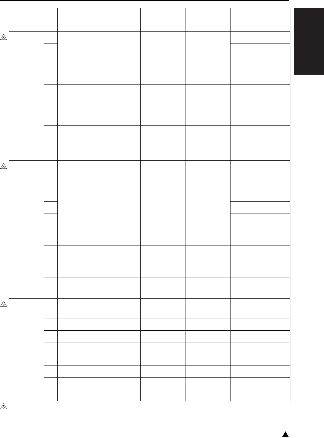
I ADJUSTMENT
25 MODE
1-21 3
DIPSW33 0 Number of punch hole *39 *39 0 0 0
1000
2 Notice of the paper feed tray
when a coin bender is being
used with APS prohibited
Invalid Valid 0 0 0
3 Change-over of the display
of FAX transmitting address
Invalid Valid 0 0 0
4 Change-over of the display
of BOX related list password
“*” Displayed Displayed
normally
000
5— ——000
6 KRDS/RDmode change (7145) KRDS RDmode 0 0 0
7 Mixplex function setting Valid Invalid 0 0 0
DIPSW34 0
System OFF setting when the
system is shut off or SW2 (sub-
power) is turned off
Not set Set 0*a0
*a0
*a
1 FS-114 paper exit tray position *40 *40 0 0 0
2000
3000
4
Printing starts when paper is
provided in the FS-114 saddle
Permit Prohibit 0 0 0
5 Correspondence to Open-
Print
Not corresponding
Corresponding 0 0 0
6 USB Print
Not corresponding
Corresponding 1 1 1
7 Overlay void setting
(7235/7228/7222 only)
Not set Set 0 0 0
DIPSW35 0 Paper exit to entire A5R fin-
isher tray
Prohibit Permit 0 0 0
1— ——000
2— ——000
3— ——000
4— ——000
5— ——000
6— ——000
7— ——000
*a In the case of the 7235/7228/7222, default value is “1”.
DIPSW No. Bit Functions 0 1 Default values
Japan Inch Metric

I ADJUSTMENT
25 MODE
1-22
3
DIPSW40 0 Use of SNMP Permit Prohibit 0 0 0
1— ——111
2— ——000
3— ——000
4— ——000
5— ——000
6— ——000
7— ——000
DIPSW No. Bit Functions 0 1 Default values
Japan Inch Metric
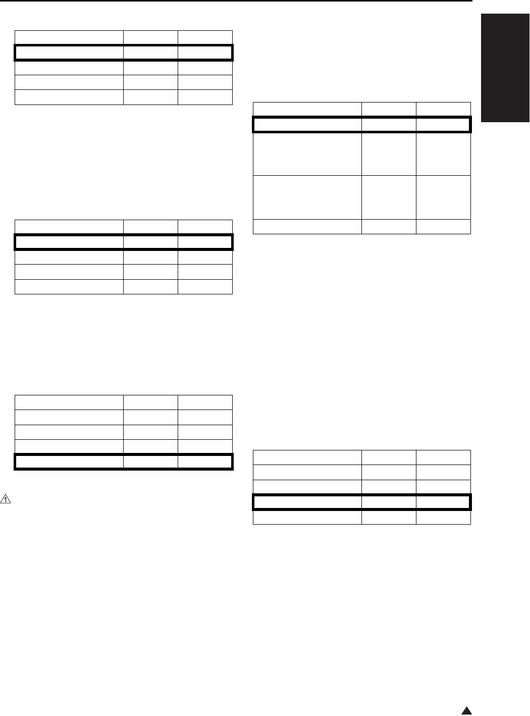
I ADJUSTMENT
25 MODE
1-23
1
*1 FS-112 stapling upper limit
*2 Toner level detection (toner supply display)
After the TLD (Toner level sensor) detects the
no toner condition for more than a specified
period of time, this sets a timing for displaying
the message “Please supply toner”.
*3 Condition for stopping copying after toner sup-
ply display
After displaying a message set in DIPSW4-0/-
1, the count up to which the copy is prohibited
is set.
*5 SW for decreased toner consumption
Decreasing the developing bias, charging grid
potential by 50V (20 step) in this setting allows
the consumption of toner to be reduced.
Increasing the potential by 50V (20 step)
allows the image density to increase a little.
*6 Timing for the polygon motor to stop/start a
low speed rotation
When the setting of the polygon motor is
made for stopping or a low speed rotation, the
motor is shifted into a low speed rotation or
stopping after the elapse of time specified by
this DIPSW. The elapsed time starts either at
one of the following:
• When the warm-up is completed.
• When the final operation of the operation keys
(except the start key)/RADF/tray while in idling.
• When the output of a copy or print job is com-
pleted.
Mode 1-4 1-3
50 sheets 0 0
45 sheets 0 1
40 sheets 1 0
35 sheets 1 1
Mode 4-1 4-0
0 effective copies 0 0
100 effective copies 0 1
200 effective copies 1 0
500 effective copies 1 1
Mode 4-3 4-2
100 effective copies 0 0
400 effective copies 0 1
700 effective copies 1 0
1000 effective copies 1 1
Mode 5-6 5-5
No adjustment 0 0
Toner consumption
increased (image den-
sity increased)
01
Toner consumption
decreased (image den-
sity decreased )
10
No adjustment 1 1
Mode 6-5 6-4
15 seconds 0 0
30 seconds 0 1
60 seconds 1 0
120 seconds 1 1
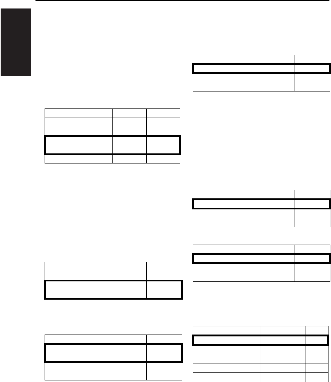
I ADJUSTMENT
25 MODE
1-24
*7 Setting of the polygon motor for stopping or
low speed rotation
In order to reduce the sound of rotation of the
polygon motor while in idling, it is possible to
switch the rotation of the polygon motor either
to a low speed rotation or stopping. The timing
for the switching is set based on *6 Timing for
the polygon motor to stop/start a low speed
rotation. When the polygon motor is stopped
or rotating at low speed, the time required for
the first copy being made is increased.
*8 Out-of-original auto erasure
When the AMS has been released due to the
original size being not the same as that of the
transfer paper size, this setting is used in the
platen copy to decide whether the out-of-origi-
nal area is erased or not. This is the same
function as the memory switch function in the
key operator mode. (Switching is not available
in the RADF copy mode.)
*9 Automatic re-starting after paper supply
(excluding inch system)
*10 Automatic conversion of the APS detected
paper size (8.5 x 11/A4)
The paper size detected by the APS is auto-
matically converted according to the standard
shown below before being copied.
*11 Switching of non-standard size notice of
platen APSA4 (Japan/Metric), 8.5 x 11 (inch)
When the original size is detected as a non-
standard size, the switching is made to decide
a copying method: a copy is made forcibly into
the following size or it is made in the size
selected as a non-standard size.
When both the DIPSW 7-3 and 7-4 are 1, the
DIPSW7-4 has preference over 7-3.
*12 Priority tray when APS is released
This setting sets the tray selection used when
APS is set OFF from key-operator mode.
Mode 6-7 6-6
No preliminary rotation
(high speed)
00
Preliminary rotation
(low speed)
01
Stopping 1 0
Mode 7-0
Out-of-original auto erasure 0
Out-of-original erasure only while in
APS/AMS
1
Mode 7-1
Re-starting by turning on the START
button
0
Re-starting by setting the tray (auto-
matic)
1
Mode 7-2
No automatic conversion 0
A4 → 8.5 x 11 (Inch)
8.5 x 11 → A4 (Japan, Metric)
1
Mode 7-3
Copied in the size selected 0
Copied forcibly as A4 (Japan, Metric)
/8.5 x 11 (Inch)
1
Mode 7-4
Copied in the size selected 0
Copied forcibly as B6 (Japan)
/A5 (Metric)/5.5 x 8.5 (Inch)
1
Mode 8-6 8-5 8-4
No priority 0 0 0
Main-body upper tray 0 0 1
Main-body lower tray 0 1 0
DB upper tray 0 1 1
DB lower tray 1 0 0
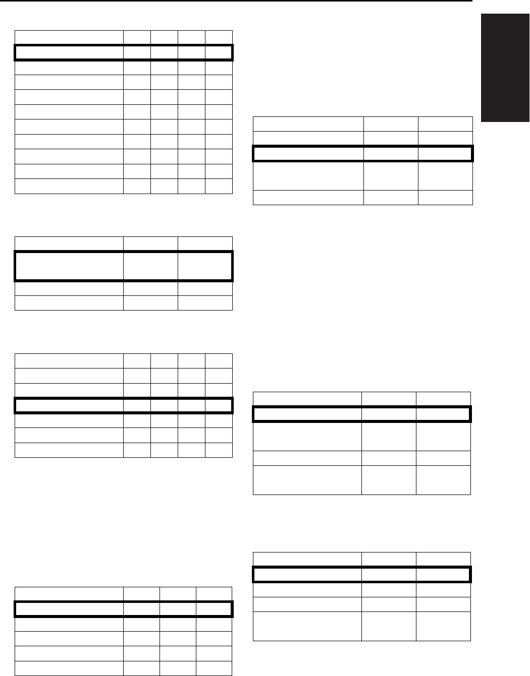
I ADJUSTMENT
25 MODE
1-25
*13 Copy quantity limit
*14 Switching of message
*15 Summer time setting
*16 Setting of the number of copies until the copy-
ing operation is prohibited when PM is
attained
If the setting of the copy prohibition when
DIPSW8-2 reaches PM is “1”, the copying
operation is stopped after the following PM
count is reached.
*17 Judging level in the out-of-original auto era-
sure mode
This setting is for the application function of
the out-of-original auto erasure mode. When
the out-of-original auto erasure is set to “auto-
matic” in the key operator mode, a threshold
value is set for detection of the original area.
*18 Operation if stapling is not possible
The positioning of staples is made against the
image of an original. Since stapling is
restricted only to the front or rear of the lead-
ing edge (the main body side of the paper
exited) of the transfer paper, or to both of
these two positions, stapling may be some-
times unavailable (when stapling is not
allowed) depending on the position specified.
This SW is used to set the operation when
stapling is not allowed.
*19 Operation when one position stapling is not
available
Mode 9-3 9-2 9-1 9-0
No limit 0 0 0 0
1 sheet 0 0 0 1
3 sheets 0 0 1 0
5 sheets 0 0 1 1
9 sheets 0 1 0 0
10 sheets 0 1 0 1
20 sheets 0 1 1 0
30 sheets 0 1 1 1
50 sheets 1 0 0 0
99 sheets 1 0 0 1
Mode 9-7 9-6
Please insert key
counter
00
Please insert copy card 0 1
Please insert coin 1 0
Mode 10-3 10-2 10-1 10-0
0 minute 0 0 0 0
30 minutes 0 0 1 1
60 minutes 0 1 1 0
90 minutes 1 0 0 1
120 minutes 1 1 0 0
150 minutes 1 1 1 1
Mode 12-5 12-4 12-3
1000 copies 0 0 0
2000 copies 0 0 1
3000 copies 0 1 0
4000 copies 0 1 1
5000 copies 1 0 0
Mode 13-7 13-6
Thick original 0 0
Normal original 0 1
Corresponding to
hybrid lights
10
—11
Mode 14-1 14-0
Auto cancel 0 0
Auto switching to 1-
position stapling
01
Inhibit 1 0
Forced 2-position sta-
pling mode operation
11
Mode 14-5 14-4
Auto cancel 0 0
Auto cancel 0 1
Inhibit 1 0
Forced 1-position sta-
pling mode operation
11
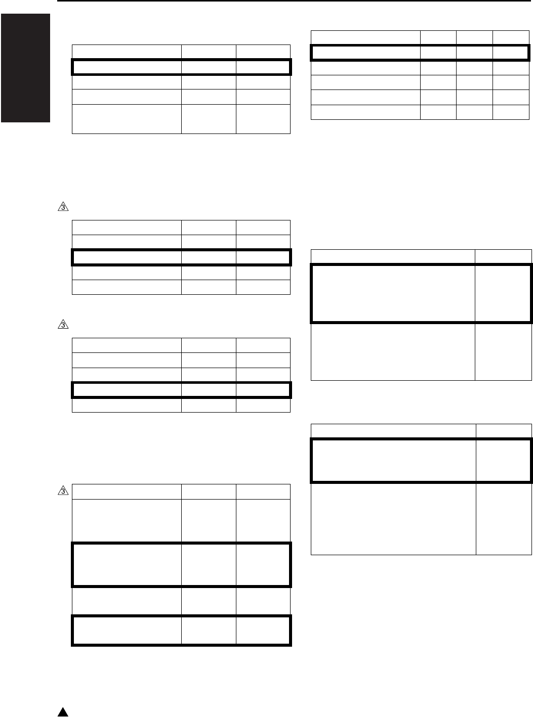
I ADJUSTMENT
25 MODE
1-26
3
*20 Operation when two position stapling is not
available
*21 Fixing temperature at low power mode
Set the fixing temperature while in the low
power mode.
In the case of the 7145
In the case of the 7235/7228/7222
*22 Dot diameter adjustment control
In this setting, the SW is used to change the
timing for the dot diameter adjustment.
*23 F4 size setting
*24 Job interruption/termination operation when
the key counter is being drawn out
This is to set the operation of the copier when
outputting a print job.
The details of the operation can be changed
by the combination of this setting and the
DIPSW1:0 setting.
*25 Switching of the count-up function
Mode 14-7 14-6
Auto cancel 0 0
Auto cancel 0 1
Inhibit 1 0
Forced 2-position sta-
pling mode operation
11
Mode 16-1 16-0
155°C 0 0
120°C 0 1
85°C 1 0
85°C 1 1
Mode 16-1 16-0
70°C 0 0
120°C 0 1
120°C 1 0
70°C 1 1
Mode 16-7 16-6
The power is off for
more than 8 hours with
humidity over 60%
00
The power is off for
more than 8 hours
(7145)
01
At all times (Every time
SW2 is turned on)
10
Non
(7235/7228/7222)
11
Mode 17-2 17-1 17-0
8.5 x 13 0 0 0
8.25 x 13 0 0 1
8.125 x 13 0 1 0
8 x 13 0 1 1
8.5 x 13.5 1 0 0
Mode 21-4
DIPSW1-0:0 Terminate by stopping
paper feed
DIPSW1-0:1 Clear jamming imme-
diately
0
DIPSW1-0:0 Interrupt by stopping
paper feed
DIPSW1-0:1 Clear jamming imme-
diately
1
Mode 21-6
Normal operation
Counting up for both the total
counter and the key counter
0
• While in copying, both the total
counter and the key counter count
up
• In the printer/FAX mode, only the
total counter counts up
1
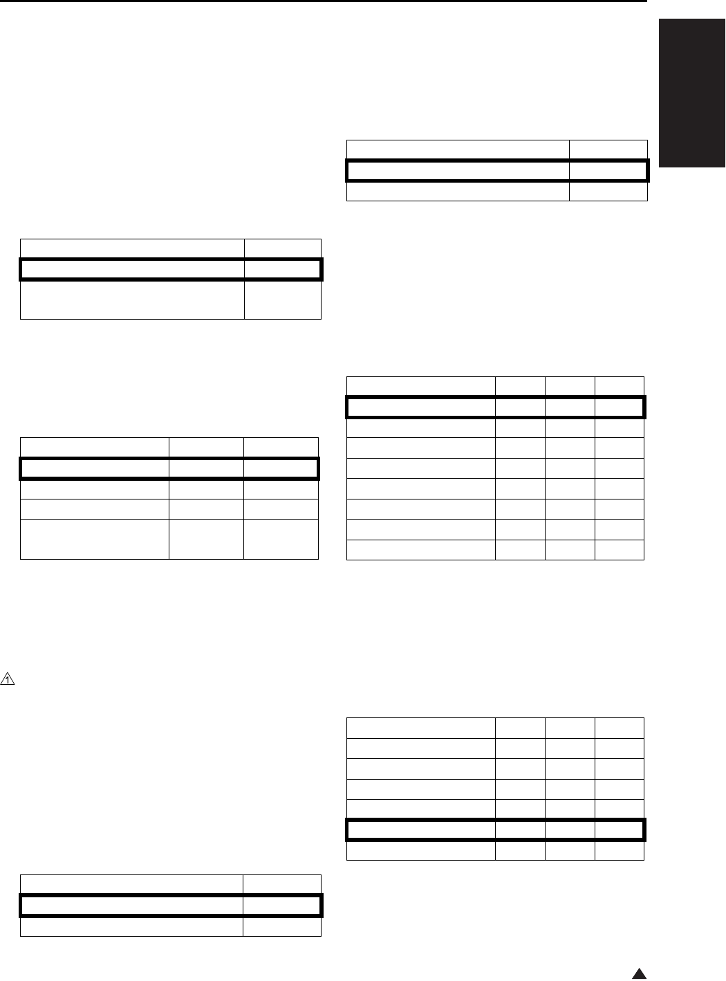
I ADJUSTMENT
25 MODE
1-27
1
*26 Automatic feed of non-standard size originals
in the platen auto start mode
The setting of the automatic selection of auto-
start is available for the memory switch setting
in the key operator mode. When this setting is
in the following condition, a setting can be
made to decide if the paper is automatically
fed from the bypass tray.
• The setting of the automatic selection of auto-
start is on with the original size (platen) detected
as non-standard.
*27 Printer paper size automatic conversion
The paper size specified by the print job is
automatically changed and output according
to the following standard.
*29 Switching of the job stop with no process stop
The SW is used to decide if a process stop is
made at the breaks between continuous two
or more jobs reserved.
*30 Automatic copy reservation function
When this setting is “1”, the copy reservation
screen automatically appears after the end of
the original read operation. Also, the job set-
tings are the same as the settings for the pre-
vious job.
*31 Density setting when the toner save function
is selected in the printer driver screen
When “Toner saving mode” is on in the printer
driver, the print density is set in the range
shown below.
This setting is effective only for the PCL and
PS versions.
*32 Selection of the transfer/separation output of
the user paper (tray)
This SW is used to set the transfer/separation
output which is applicable when the specified
paper is selected in the “Paper type setting” in
the key operator mode.
Mode 22-1
Auto start does not take place 0
Auto start takes place when the
bypass tray is selected
1
Mode 24-2 24-3
No conversion 0 0
Inch → Metric 0 1
Metric → Inch 1 0
Non (not allowed to
select)
11
Mode 24-7
No process stop 0
Process stop 1
Mode 27-0
Do not use 0
Use 1
Mode 27-7 27-6 27-5
Standard 0 0 0
-4 (Lighter) 0 0 1
-3 0 1 0
-2 0 1 1
-1 1 0 0
+1 1 0 1
+2 1 1 0
+3 (Darker) 1 1 1
Mode 29-2 29-1 29-0
Plain paper (Japan) 0 0 0
Plain paper (Inch) 0 0 1
Plain paper (Metric) 0 1 0
Thick paper 0 1 1
Thin paper 1 0 0
Recycled paper 1 0 1
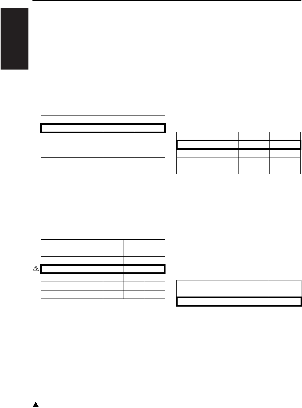
I ADJUSTMENT
25 MODE
1-28
3
*33 TSL control of user paper (tray)
This SW is used to set the TSL control which
is applicable when the specified paper is
selected in the “Paper type setting” in the key
operator mode.
When this SW is used to select the “Switched
according to the environment”, the switching
is made between “Normal control” and “All off”
according to the environment.
• “Switched according to the environment” per-
forms the TSL control according to the humidity
detected by the main body HUM1 (Humidity sen-
sor).
*34 Selection of the transfer/separation output of
user paper (bypass feed)
When selecting the bypass tray on the copy
basic screen, this SW is used to set the trans-
fer/separation output which is applicable when
selecting the user specified paper for “Special
paper setting” or the specified paper for
“Paper type setting” in the key operator mode.
*35 TSL control of user paper (bypass feed)
When selecting the bypass tray on the copy
basic screen, this SW is used to set the TSL
control which is applicable when selecting the
user paper for “Special paper setting” or the
specified paper for “Paper type setting” in the
key operator mode.
When this SW is used to select the “Switched
according to the environment”, the switching
is made between “Normal control” and “All off”
according to the environment.
• “Switched according to the environment” per-
forms the TSL controle according to the humidity
detected by the main body HUM1 (Humidity sen-
sor).
*36 Automatic power on by the RADF operation
during the power save mode
In this setting, when the following operation is
made during the power save mode, the power
is automatically turned on.
• When the original is set in RADF (when the
PS301 (No original sensor) is turned off).
• When the platen/RADF is opened (when PS15
(APS timing sensor) is turned off).
• When the platen/RADF is closed (when PS15
(APS timing sensor) is turned on).
Mode 29-4 29-3
Normal control 0 0
All off 0 1
Switched according to
the environment
10
Mode 30-2 30-1 30-0
Plain paper (Japan) 0 0 0
Plain paper (Inch) 0 0 1
Plain paper (Metric) 0 1 0
Thick paper 0 1 1
Thin paper 1 0 0
Recycled paper 1 0 1
Mode 30-4 30-3
Normal control 0 0
All off 0 1
Switched according to
the environment
10
Mode 31-0
Disabled 0
Enabled 1
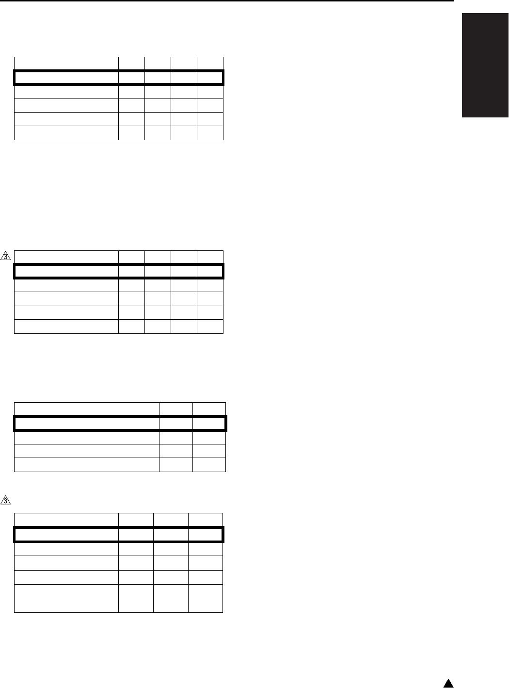
I ADJUSTMENT
25 MODE
1-29 3
*37 While rotating image during copying 1-2
mode, leading edge of the 2nd side shifts 3 to
4mm. This dipswitch is to adjust that shift.
*38 In platen copy mode, the paper exit direction
is opposite between normal copy and memory
copy. Then the image position is not the
same.
This amount of gaps is adjusted by this
dipswitch.
*39 When using FS-113 (FS-114), number of
punch holes can be set independently from
engine specifications.
*40 FS-114 paper exit tray position
Mode 28-3 28-2 28-1 28-0
+0mm 0000
+0.5mm 0001
-0.5mm 1 0 0 1
+3.5mm 0111
-3.5mm 1 1 1 1
Mode 28-7 28-6 28-5 28-4
+0mm 0000
+0.5mm 0001
-0.5mm 1 0 0 1
+3.5mm 0111
-3.5mm 1 1 1 1
Mode 33-1 33-0
Default 0 0
2-hole only 0 1
2-hole or 3-hole is selectable 1 0
4-hole only 1 1
Mode 34-3 34-2 34-1
Undefined 0 0 0
Tray 1 001
Tray 2 010
Tray 3 011
Folding/Stitch-and-fold
tray
100

I ADJUSTMENT
25 MODE
1-30
3
7.3 PM Count Setting
This function resets the PM count and sets the PM
cycle. Care should be taken to reset the PM count
properly. The PM count/cycle menu includes the fol-
lowing:
[1. PM count resetting]
[2. PM cycle setting]
[3. Counter clear]
7.3.1 PM count reset
Select whether to reset the count in the PM count
reset screen.
A. Procedure
1. Enter the 25 Mode.
2. “25 mode menu screen”
Press the [2. PM COUNT] key.
3. “PM Count/Cycle Menu screen”
Press the [1. PM count reset] key.
4. “PM Count Reset screen”
Press the [YES] key.
The PM count is reset.
Press the [NO] or [RETURN] key.
The PM count is not reset and returns to the PM
count/cycle menu screen.
7.3.2 Entering PM count start date
When resetting the PM count, it is necessary to
input the start date, and the screen below will
appear automatically.
A. Procedure
1. “PM Count Starting Date Input screen”
Enter a PM count start date from the numeric
keys.
2. Press the [SET] key to enter the data that has
been entered.
3. Press the [RETURN] key to return to the PM
count/cycle menu screen.
Note:
• When pressing the [RETURN] key without press-
ing the [SET] key, the PM count start date is not
changed. It is necessary to reset the count again
for inputting the count.
7.3.3 Setting of PM cycle
Set PM Cycle as follows:
A. Procedure
1. Enter the 25 Mode.
2. “25 mode menu screen”
Press the [2. PM COUNT] key.
3. “PM Count/Cycle Menu screen”
Press the [2. PM CYCLE Set] key.
4. “PM Cycle set screen”
Enter PM cycle from the numeric keys. Enter
upper 3-digit (hundred thousand, ten thousand,
thousand) only.
5. Press the [SET] key to enter a PM cycle that has
been entered.
6. Press the [RETURN] key to return to the PM
count/cycle menu screen.
7.3.4 Counter clear
Reference:
• The operation here is the same as [8. Counter
clear] of the “36 mode menu screen”.
The counter must be cleared whenever the drum or
fixing parts/unit is replaced.
Select the [2. PM Count] and press the [3. Counter
clear] key from the “25 mode menu screen” to dis-
play the counter clear screen.
Following menu options are available from this
screen.
• Drum related counter (Drum counter, Drum drive
counter).
• Fixing related counter (Fixing web counter).
A. Procedure
1. Enter the 25 Mode.
2. “25 mode menu screen”
Press the [2. PM Count] key.

I ADJUSTMENT
25 MODE
1-31 3
3. “PM count/cycle setting screen”
Press the [3. Counter clear] key.
4. “Counter clear screen”
Press the key corresponding to the item to be
cleared.
5. Message in the message display area will con-
firm if you really want to clear the item. Press
the [YES] key. When the item is cleared, the
“Counter clear screen” will be restored.
6. When clearing another counter, repeat above
steps 3 and 4.
7. Press the [RETURN] key twice to return to the
“25 mode menu screen”.
7.4 Data Collection
This function enables viewing of the various data
recorded in the machine. Also, it is possible for the
collected data to be checked by KRDS and man-
agement listing. The data collection menu includes
the following:
• Count data collection
• Area data collection start (Date count data)
A. Data that can be checked
Note:
• When the DIPSW8-7 is set to 0, the checking of
the collected data is limited only to No. 1.
B. Checking method of the collected data
(1) Procedure
1. Enter the 25 Mode.
2. “25 mode menu screen”
Press the [Data collection] key.
3. “Data collection menu screen”
Press the [Count data] key.
4. “Data collection screen”
Change the data number with the arrow key.
Pressing [NEXT] key enables display of next
data collection screen.
5. Press the [RETURN] key to return to the data
collection menu screen.
• The data is displayed at the line 2 in the mes-
sage display area as “Data number (No.): Count
value (00000000)”.
• Press and hold the arrow key to display the next
items continuously.
Note:
• In order to check the collected data 2 to 4, be
sure to make preparations given in “Collected
data list” in advance.
No. Classification Pre-peration
1 Copy count of each
paper size
—
RADF paper pas-
sage count
2 Count of JAM occur-
rence by each point
Enter the 25 mode
↓
Select
[1. Software SW]
↓
Set the address to
8-7:1 (Note)
3 Copy count of each
mode
4 Count of SC occur-
rence

I ADJUSTMENT
25 MODE
1-32
C. Data collection details
(1) Data collection 1
a. Copy count by each size
b. Scanner and counting of the number of FAX scans
c. Count RADF original feed quantities
Classification Size No. Paper size for destination KRDS (B1,
B6, B7, B8)Japan Metric Inch
Copy count of
each paper size
0 A3 A3 11 x 17 01
1 B4 B4 8.5 x 14 02
2 A4/A4R A4/A4R 8.5 x 11/8.5 x 11R 03
3 B5/B5R B5/B5R 5.5 x 8.5 04
4A5 A5 — 05
5B6 F4 — 06
6 8.5 x 14 — — 07
7 8.5 x 11/8.5 x 11R — A4/A4R 08
8 Metric Metric Inch 09
Special Special Special
9 Postcard — — 0A
Maximum count number : 99,999,999
Classification Size No. Feed mode KRDS (BA)
Count of the No. of
scan image planes
10 Other than 11 x 17, 8.5 x 14, A3 and B4 01
11 11 x 17, 8.5 x 14, A3 and B4 00
Maximum count number : 99,999,999
Classification Size No. Feed mode KRDS (F0)
RADF paper
passage count
15 ADF mode original feed counter 00
16 RADF mode original feed counter 01
17 ADF mixed original mode original feed counter 07
18 RADF mixed original mode original feed counter 08
Maximum count number : 99,999,999

I ADJUSTMENT
25 MODE
1-33 3
(2) Data collection 2
a. Jam occurrence count by factor
(3) Data collection 3
a. Copy count of each mode
No. Jam Point KRDS (J0)
00 10-0 By-pass 00
01 11-0 Upper tray 01
02 12-0 Lower tray 02
03 13-0 DB upper tray 03
04 14-0 DB lower tray 04
05 16-1 Paper feed jam 05
06 15-0 LT tray 06
07 16-2 LT tray 07
08 — — 08
09 30-0 Conveyance jam 09
10 31-0 Conveyance jam 0A
11 — — 0B
12 — — 0C
13 32-0
Fixing unit conveyance jam
0D
14 — — 0E
15 — — 0F
16 75-10 IT-101 10
17 75-11 11
18 — — 12
19 97-1 ADU conveyance jam 13
20 97-2 14
21 92-0 15
22 75-12 IT-101 16
23 75-13 17
24 61-1 DF-318/320 18
25 61-2 19
26 — — 1A
27 62-1 DF-318/320 1B
28 62-2 1C
29 62-3 1D
30 62-4 1E
31 62-5 1F
32 — — 20
33 63-1 DF-318/320 21
34 63-2 22
35 63-3 23
36 63-4 24
37 — — 25
38 — — 26
39 — — 27
40 — — 28
41 — — 29
42 72-16 FS-112/113 2A
43 72-17 2B
44 72-18 FS-113 2C
45 72-19 FS-112 2D
46 72-21 FS-112/113 2E
47 72-23 FS-112 2F
48 72-81 FS-112/113 30
49 72-82 FS-113 31
50 72-83 32
51 72-25 FS-114 33
52 72-43 34
53 72-84 35
54 72-85 36
55 — — 37
:
79 — — 4F
80 — — 50
Maximum count number : 999,999
No. Contents
KRDS (F1)
00 Platen single side → single side 00
01 — 01
02 RADF double side → single side 02
03 RADF double side → double side 03
04 RADF single side → single side 04
05 RADF single side → double side 05
06 Finisher (Staple mode) 06
07 Finisher (Sort mode) 07
08 Finisher (Group mode) 08
09 Finisher (Number of stapling) 09
10 Life-size 0A
11 Fixed ratio E3(1.41/2.00) 0B
12 Fixed ratio E2(1.22/1.55) 0C
13 Fixed ratio E1(1.15/1.29) 0D
14 Fixed ratio R1(0.86/0.77) 0E
15 Fixed ratio R2(0.82/0.65) 0F
16 Fixed ratio R3(0.71/0.50) 10
17 User set magnification 11
18 Zoom 12
19 Maximum zoom 13
20 Minimum zoom 14
21 AMS mode 15
22 APS mode 16
23 AE mode 17
24 Interrupt mode 18
No. Jam Point KRDS (J0)

I ADJUSTMENT
25 MODE
1-34
3
25 By-pass feed mode 19
26 Book copy mode 1A
27 Frame erase mode 1B
28 Fold erase mode 1C
29 Image shift mode 1D
30 Reduction image shift mode 1E
31 — 1F
32 — 20
33 Number of paper feed quantities
at intersheet mode
21
34 — 22
35 Number of feed in the OHP mode
(blank paper interleave)
23
36 Number of paper feed quantities
at mixed original mode
24
37
Access number of the JOB memory call
mode (Number of pressing the
∗
button)
25
38 Number of times the auto low
power mode is used
26
39 Number of starting copy with
copy quantity is set to 1
27
40
Number of starting copy with copy
quantity is set between 2 and 5
28
41
Number of starting copy with copy
quantity is set between 6 and 10
29
42
Number of starting copy with copy
quantity is set to 11 or above
2A
43 Number of starting copy in inter-
sheet mode
2B
44 — 2C
45 Photo mode 2D
46 Passage count in the ADF thick
paper mode
2E
47 Verti./Horiz. zoom mode 2F
48 Memory copy mode 30
49 Proof copy mode 31
50 Text/Photo mode 32
51 Text mode 33
52 User set density mode 34
53 Number of feed in the OHP mode
(copy interleave)
35
54 — 36
55 — 37
56 Cover insertion mode 38
57 Chapter mode 39
58 2 in 1, 4 in 1, 8 in 1 mode 3A
No. Contents
KRDS (F1)
59 Repeat mode 3B
60 Reverse image mode 3C
61 Non-image area erase mode 3D
62 Increase contrast mode 3E
63 Auto layout mode 3F
64 — 40
65 Number of copies in rotation 41
66
Copy quantity of paper feed from tray 1
42
67
Copy quantity of paper feed from tray 2
43
68
Copy quantity of paper feed from tray 3
44
69
Copy quantity of paper feed from tray 4
45
70 — 46
71 — 47
72
Finisher, Number of stapling (front)
48
73
Finisher, Number of stapling (rear)
49
74 Booklet mode copying count 4A
75 OHP mode (without doubled
sheet) copying count
4B
76 Z-fold mode copying count 4C
77 Copy quantity in the non-stan-
dard size mode
4D
78
Stamping/overlay mode copying count
4E
79 Flip side 2 mode copying count 4F
80
Number of copies in the punch mode
50
81 — 51
82 Number of copies in the thick
paper 1 copy mode
52
83 Number of copies in the thick
paper 2 copy mode
53
84 Number of copies in the plain
paper mode
54
85 Number of copies in the thin
paper mode
55
86 Number of copies in the recycled
paper mode
56
87 Number of copies in the user
specified paper mode
57
Maximum count number : 99,999,999
No. Contents
KRDS (F1)

I ADJUSTMENT
25 MODE
1-35 3
(4) Data collection 4
a. Count number of SC occurrence
No. Error code
(decimal number)
Classification KRDS
Main code
Sub code
001 10-1 Communication error E0 00
002 10-2 01
003 — — 02
004 18-1 Paper feed tray error 03
005 18-2 04
006 18-3 05
007 18-4 06
008 26-1 L detection error 07
009 28-1 High voltage power
error
08
010 28-2 09
011 28-3 0A
012 34-1
High fixing temperature
abnormality
0B
013 34-2 0C
014 35-1 Low fixing tempera-
ture abnormality
0D
015 35-2 0E
016 35-3 0F
017 35-4 10
018 35-5 11
019 35-6 Low fixing tempera-
ture abnormality
E0 12
020 35-7 13
021 35-8 14
022 35-9 15
023 35-10 16
024 36-1 Fixing sensor error 17
025 36-2 18
026 36-3 19
027 — 1A
028 40-1 Scanning system
error
1B
029 40-9 1C
030 41-1 1D
031 46-1 Image processing
system error
1E
032 46-8 1F
033 46-10 20
034 46-11 21
035 — — 22
036 49-4 Image processing
system error
23
037 49-6 24
038 51-4 Motor speed error 25
039 51-5 26
040 51-6 27
041 52-1 Fan lock error 28
042 52-2 29
043 E56-1 Image control
communication error
E1 00
044 E56-2 01
045 E56-3 02
046 E56-4 03
047 E56-5 04
048 E56-6 Operation control
section system error
05
049 E56-7 06
050 E56-8 07
051 E56-9 08
052 E56-10 09
053 — — E0 2A
054 60-1 RADF error 2B
055 60-9 2C
056 60-11 2D
057 67-3 2E
058 70-1 Finisher error 2F
059 70-9 30
060 70-11 31
061 77-2 32
062 77-3 33
063 77-5 Finisher error E0 34
064 77-6 35
065 77-11 36
066 77-16 37
067 80-1 Parameter memory
board abnormality
38
068 80-2 39
069 80-3 3A
070 80-4 3B
071 80-5 3C
072 81-1 Flash ROM error 3D
073 81-2 3E
074 81-3 3F
075 E88-1 Image processing
system error
E1 0A
076 E89-1
System control board
communication error
0B
077 E89-2 0C
078 E89-3 0D
079 E89-4 0E
080 E89-5 0F
081 E89-6 10
082 E87-1
Print controller error
11
083 52-5 Fan lock error E0 40
084 86-2 Fax board error 41
085 86-3 42
No. Error code
(decimal number)
Classification KRDS
Main code
Sub code
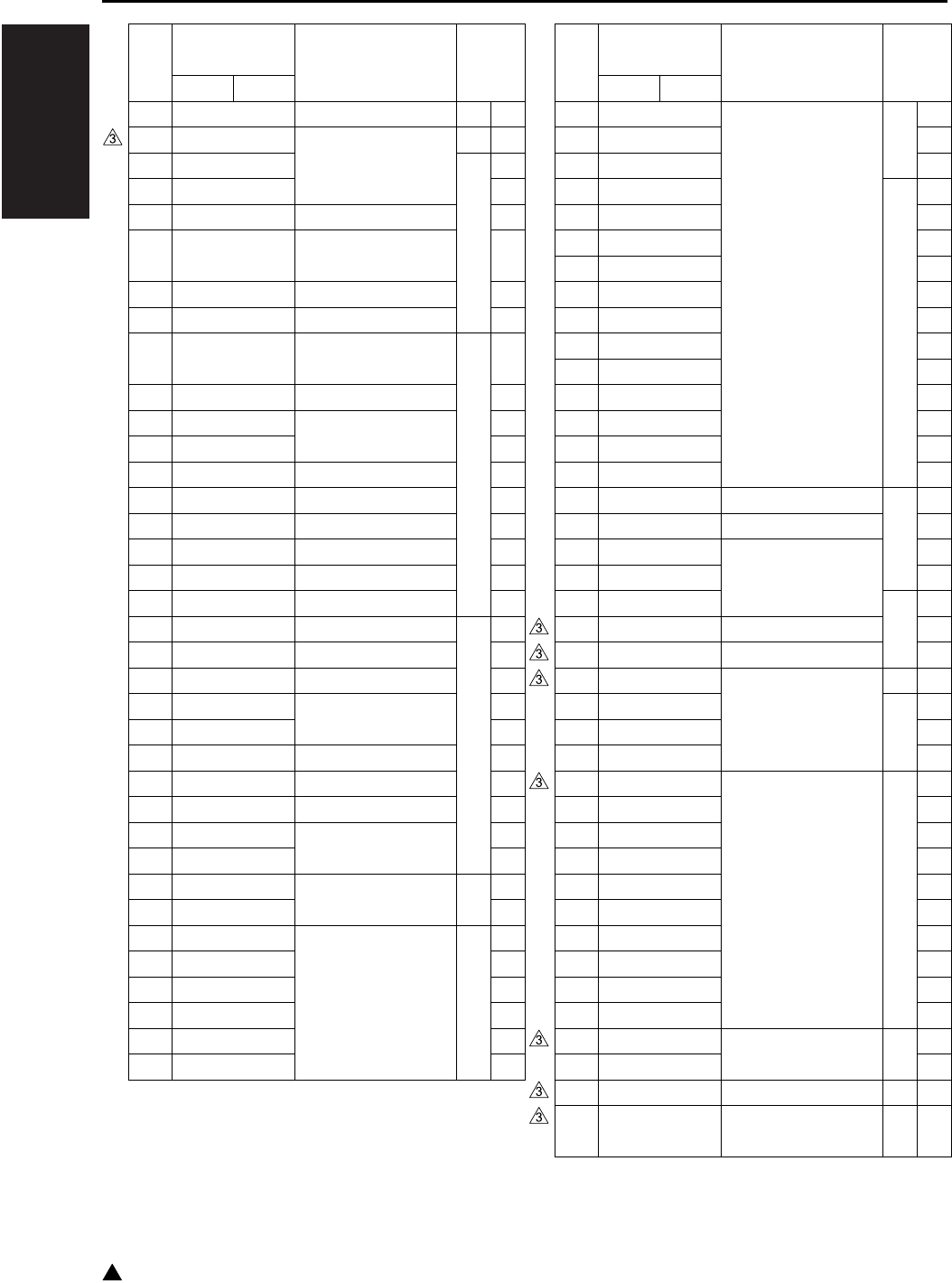
I ADJUSTMENT
25 MODE
1-36
3
086 E86-04 Fax board error E1 12
087 E86-06 Fax error (System
control board side)
E0 43
088 E86-88 E1 13
089 E86-89 14
090 — — 15
091 E86-91 Fax error (System
control board side)
16
092 — — 17
093 E86-20
Fax error (Fax board side)
18
094 22-1 Machine internal
temperature
E0 44
095 23-1 Drum periphery 45
096 26-2 L detection 46
097 26-3 47
098 28-4 — 48
099 43-1
Scanning system error
49
100 52-3 Fan lock error 4A
101 36-4
Broken fixing sensor
4B
102 52-6 Fan lock error 4C
103 87-2 Print controller error 4D
104 87-3 Print controller error E0 4E
105 — — 4F
106 52-4 Fan lock error 50
107 86-7 Fax board error 51
108 86-8 52
109 18-5 Paper feed tray error 53
110 26-4
High voltage power error
54
111 51-2 Motor speed error 55
112 52-7 Fan lock error 56
113 52-8 57
114 E56-12
System control board
communication error
E1 19
115 E56-13 1A
116 77-1 Finisher error E0 58
117 77-4 59
118 77-12 5A
119 77-17 5B
120 77-54 5C
121 77-55 5D
No. Error code
(decimal number)
Classification KRDS
Main code
Sub code
122 85-1 Network system
abnormality
E0 5E
123 85-2 5F
124 85-3 60
125 E85-11 E1 1B
126 E85-12 1C
127 E85-13 1D
128 E85-14 1E
129 E85-15 1F
130 E85-16 20
131 E85-17 21
132 E85-18 22
133 E85-20 23
134 E85-21 24
135 E85-22 25
136 E85-23 26
137 52-9 Fan lock error E0 61
138 81-4 Flash ROM error 62
139 82-1
Document manager error
63
140 82-2 64
141 E82-10 E1 27
142 E89-80 CPU hang up-1 28
143 E89-81 CPU hang up-2 29
144 82-3 I-FAX system error E0 65
145 E82-50 E1 2A
146 E82-51 2B
147 E82-52 2C
148 77-13 Finisher error E0 66
149 77-14 67
150 77-22 68
151 77-23 69
152 77-24 6A
153 77-25 6B
154 77-26 6C
155 77-27 6D
156 77-28 6E
157 77-29 6F
158 E85-24 Network system
abnormality
E1 2D
159 E85-25 2E
160 52-10 Fan lock error E0 70
161 E85-30 Network system
abnormality
E1 2F
Maximum count number : 9,999
No. Error code
(decimal number)
Classification KRDS
Main code
Sub code

I ADJUSTMENT
25 MODE
1-37 3
D. Starting periodic date collection
Reset the periodic data from the setting peri-
odic collection start date. Make a date that this
operation is performed as a new periodic col-
lection start date.
The periodic data can be checked with the
KRDS/RDmode (7145) and management list.
(1) Procedure
1. Enter the 25 mode.
2. “25 mode menu screen”
Press the [3. Collecting data] key.
3. “Data collection menu screen”
Press the [2. Starting periodic data collection]
key.
4. “Starting periodic data collection screen”
Press the [YES] key to start the periodic data
collection.
Press the [NO] or [RETURN] key, then data col-
lection start date is not reset and returns to the
data colleciton menu screen.
7.5 Copy Count for Each Part to
be Replaced
Perform the copy count display, count clear, limit
value setting and arbitrarily parts to be replaced set-
ting to the data of the parts to be replaced (fixed/
arbitrarily).
Each count value can be check with the manage-
ment list of 36 Mode and the KRDS/RDmode
(7145). The following are included in the part
counter menu:
• Copy Count for each fixed replacement part
• Copy Count for each arbitrarily replacement part
7.5.1 Copy count by parts to be replaced (fixed)
Set the parts name of the fixed parts to be replaced
(fixed), parts No. and copy count display, and count
reset.
A. Procedure
1. Enter the 25 Mode.
2. “25 mode menu screen”
Press the [4. Parts counter] key.
3. “Parts counter menu screen”
Press the [1. Count of parts (Fixed)] key.
4. “Copy count screen by parts to be replaced
(fixed)”
Press the arrow keys to select the data.
5. Press the [Count reset] key.
6. “Count reset screen by parts to be replaced
(fixed)”
Press the [YES] key to clear the copy count.
Press the [NO] or [RETURN] key, then the copy
count is not reset and returns to the copy count
screen by parts to be replaced.

I ADJUSTMENT
25 MODE
1-38
3
B. List of parts to be replaced (fixed)
No. Unit Parts name
KRDS
(Z1)
01 DC (includ-
ing charging
corona unit)
Drum 00
02 Cleaning blade
assembly
01
03 Drum unit 02
04 Transfer/
separation
corona
Transfer/separation
corona unit
03
05
Developing unit
Developer 04
06 Developing unit 05
07 Main body Ozone filter 06
41 Suction filter/A 27
42 Filter cover assembly 28
08 Main body
paper feed
unit
(Tray 1) Paper feed
rubber
07
09 (Tray 1) Feed ubber 08
10 (Tray 1) Double feed
prevention rubber
09
11 (Tray 2) Paper feed
rubber
0A
12 (Tray 2) Feed ubber 0B
13 (Tray 2) Double feed
prevention rubber
0C
14 DB-211/411 (Tray 3) Paper feed
rubber
0D
15 (Tray 3) Feed ubber 0E
16 (Tray 3) Double feed
prevention rubber
0F
17 DB-211 (Tray 4) Paper feed
rubber
10
18 (Tray 4) Feed ubber 11
19 (Tray 4) Double feed
prevention rubber
12
20 By-pass
feed unit
Double feed preven-
tion roller
13
21 Paper feed roller 14
22 Feed roller 15
23 Fixing unit Fixing heat roller 16
24 Fixing pressure roller 17
25
Fixing cleaner assembly
18
26
Heat insulating sleeve/A
19
27
Heat insulating sleeve/B
1A
28 Fixing idler gear/B 2
29 — 1C
30 Fixing claw 1D
31 Fixing roller holder/U 1E
32 Fixing roller holder/L 1F
33 Fixing sensor 20
34 Fuse mounting plate
assembly
21
35 Fixing heater lamp/1 22
36 Fixing heater lamp/2 23
37 DF-318/320 Paper feed roller 24
38 Feed roller 2C
39 Double feed preven-
tion roller
25
40 FS-112 Paper exit roller/A 26
43 LT-203 Paper feed rubber 29
44 Feed rubber 2A
45 Double feed preven-
tion rubber
2B
No. Unit Parts name
KRDS
(Z1)

I ADJUSTMENT
25 MODE
1-39
7.5.2 Copy count by parts to be replaced
(Named; arbitrarily)
Set the limit value for the parts to be replaced, parts
No., parts name setting, copy count display and
count reset.
A. Copy count display and count reset by parts
to be replaced
(1) Procedure
1. Enter the 25 Mode.
2. “25 mode menu screen”
Press the [4. Parts counter ] key.
3. “Parts counter menu screen”
Press the [2. Count of parts (Named)] key.
4. “Copy count screen by parts to be replaced
(named)”
Press the arrow key to select the data to be set
or changed.
5. The following items can be set below:
• “COUNT RESET” : To clear the copy count.
• “LIMIT SET” : To enter the limit value (6-digit).
• “P/N SET” : To enter the parts number (9-digit).
• “Parts name” : To enter the parts name.
6. Press the [RETURN] key, then return to the
“Copy screen by parts to be replaced”.
B. List of parts to be replaced (arbitrarily)
No. Count timing
KRDS
(G0)
00
When copy count (at the paper exit is completed)
00
01
When copy count (at the paper exit is completed)
01
02
When copy count (at the paper exit is completed)
02
03
When copy count (at the paper exit is completed)
03
04
When copy count (at the paper exit is completed)
04
05
When copy count (at the paper exit is completed)
05
06
When copy count (at the paper exit is completed)
06
07
When copy count (at the paper exit is completed)
07
08
When copy count (at the paper exit is completed)
08
09
When copy count (at the paper exit is completed)
09
10
When copy count (at the paper exit is completed)
0A
11
When copy count (at the paper exit is completed)
0B
12
When copy count (at the paper exit is completed)
0C
13
When copy count (at the paper exit is completed)
0D
14
When copy count (at the paper exit is completed)
0E
15
When copy count (at the paper exit is completed)
0F
16
When copy count (at the paper exit is completed)
10
17
When copy count (at the paper exit is completed)
11
18
When copy count (at the paper exit is completed)
12
19 When paper is fed from LT-203 13
20 When paper is fed from by-pass tray 14
21 When paper is fed from tray 1 15
22 When paper is fed from tray 2 16
23 When paper is fed from tray 3 17
24 When paper is fed from tray 4 18
25 When paper is fed from ADU 19
26 When paper is exited from main body 1A
27
When RADF is read (1 count each for front and back)
1B
28
When RADF is read (1 count each for front and back)
1C
29
When RADF is read (1 count each for front and back)
1D

I ADJUSTMENT
25 MODE
1-40
C. Count resetting method
(1) Procedure
1. Enter the 25 Mode.
2. “25 mode menu screen”
Press the [4. Parts counter ] key.
3. “Parts counter menu screen”
Press the [2. Count of parts (Named)] key.
4. “Copy count screen by parts to be replaced
(named)”
Press the arrow keys to select the data.
5. Press the [COUNT RESET] key.
6. “Count reset screen by parts to be replaced
(named)”
Press the [YES] key to clear the copy count that
has been selected.
Press the [NO] or [RETURN] key, then the copy
count is not reset and returns to the “Copy count
screen by parts to be replaced (named)”.
D. Count limit setting method
Enter the new limit value from the numeric keys
on the screen.
(1) Procedure
1. Enter the 25 Mode.
2. “25 mode menu screen”
Press the [4. Parts counter ] key.
3. “Parts counter menu screen”
Press the [2. Count of parts (Named)] key.
4. “Copy count screen by parts to be replaced
(named)”
Press the arrow key to select the data to be set
or changed.
5. Press the [LIMIT SET] key.
6. “Copy count limit setting screen by parts to be
replaced (named)”
Enter new value using the numeric keys.
7. Press the [SET] key to enter the limit value that
has been entered.
8. Press the [RETURN] key to return to the copy
count screen by parts to be replaced (named).
Note:
• When pressing the [RETURN] key without press-
ing the [SET] key, the setting is complete without
changing a new limit value and returns to the
copy count screen by parts to be replaced
(Named).
Reference:
• The right side of the limit value will be marked “∗”
if the copy count exceeds its limit value.
E. Parts No. setting
Enter the new parts No. (9-digit) from the
numeric keys and alphabet keys on the screen.
(1) Procedure
1. Enter the 25 Mode.
2. “25 mode menu screen”
Press the [4. Parts counter ] key.
3. “Parts counter menu screen”
Press the [2. Count of parts (Named)] key.
4. “Copy count screen by parts to be replaced
(named)”
Press the arrow key to select the data to be set
or changed.
5. Press the [P/N SET] key.
6. “Part No. setting screen by parts to be replaced
(named)”
Enter new parts No. using the numeric and
alphabet keys.
7. Press the [SET] key to enter the limit value that
has been entered.
8. Press the [RETURN] key to return to the copy
count screen by parts to be replaced (named).
Note:
• When pressing the [RETURN] key without press-
ing the [SET] key, the setting is complete without
changing a new parts No. and returns to the copy
count screen by parts to be replaced (Named).

I ADJUSTMENT
25 MODE
1-41 3
F. Parts name setting
Enter the new parts name from the keys on the
screen.
There are three screen in the input screen and
are changed with the arrow key:
• Alphabet (a capital letter), numeric number
• Alphabet (a small letter), numeric number
• Symbol, numeric number
The key arrangement can be changed by press-
ing the [Keyboard] key in the alphanumeric
(uppercase letter/lowercase letter), symbol and
data input screen.
(1) Procedure
1. Enter the 25 Mode.
2. “25 mode menu screen”
Press the [4. Parts counter ] key.
3. “Parts counter menu screen”
Press the [2. Count of parts (Named)] key.
4. “Copy count screen by parts to be replaced
(named)”
Press the arrow key to select the data to be set
or changed.
5. Press the [P/N SET] key.
6. “Parts name setting screen by parts to be
replaced (named)”
Enter new parts name using the keys on the
screen.
7. Press the [OK] key to enter the parts name that
has been entered and return to the copy count
screen by parts to be replaced (Named).
Note:
• When pressing the [CANCEL] key without press-
ing the [OK] key, the setting is completed without
setting a parts name and returns to the copy
count screen by parts to be replaced (Named).
7.6 Password Setting
The following passwords are set.
• Key operator password (8-digits): Password to
enter key operator mode when security
enhancement is enabled.
• User account (EKC) master key code (8 digits):
An EKC master key code that is required when
entering various EKC setting modes.
• Weekly timer password (4 digits): A weekly timer
password that is required when entering various
weekly timer setting modes.
• CE password (8-digits): Password for CE to
access service modes when security enhance-
ment is enabled.
A. Procedure
1. Enter the 25 Mode.
2. Press the [5. Password setting] key.
3. “Password setting menu screen”
Press the key of an item that you want to set.
• [Key Operator Password (8 digits)]
• [User account (EKC) master key code (8 digits)]
• [Weekly timer Password (4 digits)]
• [CE Password (8 digits)]
4. Input a new password through the numeric keys
and press the [SET] key to update the pass-
word.
When the following keys are set for the pass-
word, each mode can be used without a pass-
word.
• “0000” : Weekly timer Password
• “00000000”: User account (EKC) master key
code
5. Repeat the procedures 3 and 4 to set pass-
words for other items.
6. Press the [RETURN] key to return to the pass-
word setting menu screen.
Note:
• When pressing the [RETURN] key without press-
ing the [SET] key, the setting is complete. How-
ever the new password will not be entered and
the password setting menu screen will return.
• Do not use name, your birthday or employee
code number as the password since other people
can easily guess them.

I ADJUSTMENT
25 MODE
1-42
3
• The administrator should not inform other people
of the password.
7.7 Setting Phone Number of the
Service Center
This function displays the telephone and fax num-
bers (Max. 21 digits) of the service center which is
indicated on the screen if a service call is required.
This function is not related to KRDS/RDmode
(7145) functions. It is designed only for indicating
the data on the screen.
A. Procedure
1. Enter the 25 Mode.
2. “25 mode menu screen”
Press the [6. Service TEL No.] key.
3. “Service center number setting screen”
Press either of the [TEL] or [FAX] key which you
want to set.
4. Input the telephone number or fax number
through the numeric keys and press the [SET]
key to update the telephone number or fax num-
ber.
5. When setting both the telephone number and
the fax number, repeat the procedures 3 and 4
above.
6. Press the [RETURN] key to return to the “25
mode menu screen”.
Note:
• When pressing the [RETURN] key without press-
ing the [SET] key, the setting is complete. How-
ever the new phone number will not be entered
and the “25 mode menu screen” will return.
7.8 Setting the Serial Number/
the Destination
7.8.1 Setting the serial number
This function is used to display, set and change the
serial number of the main body and optional units.
The serial numbers can be read from KRDS/
RDmode (7145).
A. Procedure
1. Enter the 25 Mode.
2. “25 mode menu screen”
Press the [7. Serial number] key.
3. “Serial number setting menu screen”
From among the keys, press the key of an item
you want to change.
4. “Serial number setting screen”
Enter the 9-digit serial number from the alpha-
bet and numeric keys on the screen and then
press the [SET] key to enter the number that
has been entered.
Reference:
• Characters input are entered at the least signifi-
cant digit and displayed while shifting from right to
left.
5. Repeat the procedures 3 and 4 to set the serial
numbers of other items.
6. Press the [RETURN] key to return to the “Serial
number setting menu screen”.
Note:
• When pressing the [RETURN] key without press-
ing the [SET] key, the setting is complete. How-
ever the new serial number will not be entered
and the “Serial number setting menu screen” will
return.

I ADJUSTMENT
25 MODE
1-43
7.8.2 Setting the destination
To change the destination setting, press the [Desti-
nation] key on the serial number setup menu. The
procedure is as follows.
A. Procedure
1. Enter the 25 Mode.
2. “25 mode menu screen”
Press the [7. Serial No.] key.
3. “Serial number setting screen”
Press the [Destination] key.
4. “Destination setting screen”
Use the arrow key to select the destination.
5. Press the [OK] key to register the setting.
Note:
• If you press [CANCEL] key, the copier will retain
the previous destination setting and return you to
the “Serial number setting screen”.
6. Press the [RETURN] key to return to the “25
mode menu screen”.
Destination codes
7.9 Displaying the ROM Version
Display ROM version mounted to the machine.
A. Procedure
1. Enter the 25 Mode.
2. “25 mode menu screen”
Press the [ROM version] key.
3. “ROM version display screen”
• System control
• Image control
• Panel control
• Optical control
• Various options
If any option is not installed, its relevant position
remains blank.
4. Press the [RETURN] key to return to the “25
mode menu screen”.
7.10 KRDS Setting
See the “Manual for KRDS”.
7.11 ISW Setting
See the chapter “ISW”.
7.12 Root Counter Display
The root counter (total counter can be checked in
25 mode on the root counter display.
A. Procedure
1. Enter the 25 Mode.
2. “25 mode menu screen”
Press the [11. Root counter] key.
3. “Root counter display screen”
Values of the root counter (total counter) are dis-
played.
4. Press the [RETURN] key to return to the “25
mode screen”.
Code Destination Code Destination
JP Japan IE Ireland
CA Canada FI Finland
US U.S.A SE Sweden
KR Korea NO Norway
SG Singapore AT Austria
MY Malaysia BE Belgium
CN China NL Netherlands
SA Saudi Arabia CH Switzerland
TW Taiwan FR France
ZA South Africa GB Great Britain
PL Poland DE German
PT Portugal EU Europe
ES Spain NZ New Zealand
IT Italy AU Australia
DK Denmark

I ADJUSTMENT
25 MODE
1-44
7.13 Setting Date
Set the total count start day.
A. Procedure
1. Enter the 25 Mode.
2. “25 mode menu screen”
Press the [12.Setting date] key.
3. “Setting date screen”
Using the numeric keys, enter the year, month
and day in that sequence.
4. Press the [OK] key to return to the “25 mode
screen”.
Note:
• Ends when the [CANCEL] key is pressed without
amending the entered date, and returns to the “25
mode menu screen”.
7.14 Tray Size Setting
This setting is made when changing the paper size
of the option tray (LT-203). The paper size that can
be selected is only A4 and 8.5 x 11.
A. Procedure
1. Enter the 25 mode.
2. “25 mode menu screen”
Press the [13. Tray size setting] key.
3. “Tray size setting screen”
Press the arrow key to change the paper size of
the LT-203.
4. Press the [RETURN] key to return to the “25
mode menu screen”.

I ADJUSTMENT
36 MODE
1-45 3
8. 36 MODE
8.1 Setting Method
A special operating mode called “36 Mode” has
been provided with this machine. This mode
enables adjustment of the various parts.
A. Procedure
1. Turn the SW2 (sub power switch) OFF when the
SW1 (main power switch) remains ON.
2. Turn the SW2 ON while pressing 3 and 6 of the
copy quantity setting buttons.
If security enhancement is enabled, the CE
password input request screen appears. In put
CE password.
36 mode menu screen appears. At this moment,
the machine turns to 36 mode and normal copy
operation is disabled.
3. Press the desired item key on the LCD screen.
Each setting screen will appear.
4. Enter data in each setting screen.
5. Press the [RETURN] key to check the data that
has been entered.
6. Turn the SW2 OFF to cancel the 36 mode.
7. New data will be effective after restarting.
Note:
• If FNS is not installed, the [FNS adj.] key is netted
and neither key can be selected.
8.2 Process Adjustment
Adjust the L detection, various high voltages, devel-
oper toner density, dot diameter, and the laser off-
set.
A. Procedure
1. Select [1. Process adjustment] in the 36 mode
menu screen and display the “Process adjust-
ment menu screen”.
2. The following items are shown on the “Process
adjustment menu screen”.
• Charging voltage value adjustment
• Transfer current adjustment
• Separation (AC) voltage adjustment
• Separation (DC) voltage value adjustment
• Charging grid voltage adjustment
• Developing bias adjustment
• L detection adjustment
• Automatic toner supply
• Toner density adjustment
• Dot diameter adjustment
• LD1 offset adjustment
• LD2 offset adjustment (7145 only)
• LD1 bias adjustment
• LD2 bias adjustment (7145 only)
3. Press the arrow key until the item you want to
adjust appears. The adjustment screen of the
selected item is displayed.
4. Press the [Preceding screen] of each process
adjustment screen to return to “Process adjust-
ment menu screen”.
(1) Process adjustment—Charging voltage value
adjustment
• Charging voltage value adjustment is inhibited in
the field.
(2) Process adjustment—Transfer current adjust-
ment
• Transfer current adjustment is inhibited in the
field.
(3) Process adjustment—Separation (AC) voltage
adjustment
• Separation (AC) voltage adjustment is inhibited
in the field.
(4) Process adjustment—Separation (DC) voltage
value adjustment
• Separation (DC) voltage value adjustment is
inhibited in the field.
(5) Process adjustment—Charging grid voltage
adjustment
• Charging grid voltage adjustment is inhibited in
the field.
(6) Process adjustment—Developing bias adjust-
ment
• Developing bias adjustment is inhibited in the
field.
(7) Process adjustment—L detection adjustment
• See “L detection adjustment”.
(8) Process adjustment—Automatic toner supply
• Normally carried out automatically, and the pro-
cess adjustment - automatic toner supply is not
made in the field.

I ADJUSTMENT
36 MODE
1-46
3
(9) Process adjustment—Toner density adjustment
• See “Toner density adjustment”.
(10) Process adjustment—Dot diameter adjustment
• See “Dot diameter adjustment”.
(11) Process adjustment—LD1 offset adjustment
• See “LD1 offset adjustment”.
(12) Process adjustment—LD2 offset adjustment
(7145 only)
• See “LD2 offset adjustment”.
(13) Process adjustment—LD1 bias adjustment
• The LD1 bias adjustment is not made in the field.
(14) Process adjustment—LD2 bias adjustment
(7145 only)
• The LD2 bias adjustment is not made in the field.
8.3 L Detection Adjustment
This adjustment be made immediately after replace-
ment of the developer (before any copies are made
with the new developer). Developing counter is
automatically reset.
Note:
• After replacing the developer, do not make copies
until you have performed L detection adjustment.
A. Procedure
1. Enter the 36 mode.
2. “36 mode menu screen”
Press the [1. Process adjustment] key.
3. “Process adjustment screen”
Press the arrow key until the “L detection adjust-
ment value”. appears in the message display area.
4. “L detection adjustment screen”
Press the [START] key, then confirm that [OK] is
displayed at “Result” and the L detection data value.
5. Press the [RETURN] key to return to the “36
mode menu screen”.
Note:
• If an OK indication does not appear after the
developer has been agitated, it means that an L
detection adjustment error has occurred. In this
case, an error code will appear in the “Result” dis-
play area. For the meaning of error codes, refer to
the “L detection error code list” of “List of error
codes”.
8.4 Toner Density Adjustment
The developer toner density can be increased or
decreased by making this adjustment.
Major cases in which this adjustment is used:
• When the image fogging has occurred due to the
increased density in the developer toner density.
(In this case, reduce the toner density.)
Preparation: The drum cartridge must be set in
advance.
A. Procedure
1. Enter the 36 mode.
2. “36 mode menu screen”
Press the [1. Process adjustment] key.
3. Press the arrow key repeatedly until the “Toner
density adjustment” is displayed in the message
column.
4. “Toner density adjustment screen”
Select the set value [-2] to [+2], and press the
[START] key.
• Set value: -2 (toner density decreased) to +2
(toner density increased)
• When [Current set value] → [New set value] =
the same, return the toner density to the normal
level.
• When [Current set value] → [New set value] = +
(plus), increase the transient level of the toner
density.
• When [Current set value] → [New set value] = -
(minus), decrease the transient level of the toner
density.
According to the value set, the toner density is
automatically adjusted. When the adjustment is
terminated in about 250 seconds.
5. Press the [RETURN] key to return to the “36
mode menu screen”.
Note:
• When an error code is displayed while in the
toner density adjustment, conduct the toner den-
sity adjustment again after checking the expected
defective parts on the error code list.
F26-3: TDS (Toner density sensor output abnor-
mality)
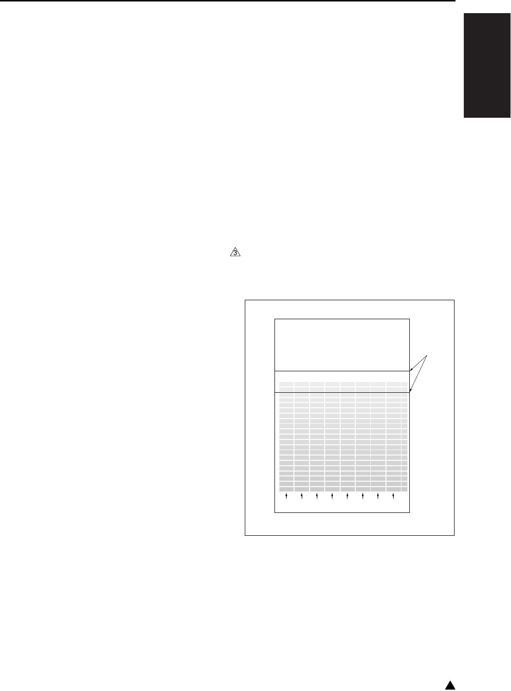
I ADJUSTMENT
36 MODE
1-47 3
8.5 Dot Diameter Adjustment
The MPC value can be corrected to change the
image density (dot diameter) by entering a setting.
(Common to copier/printer/fax)
Major cases in which this adjustment is used:
• When you want to change the image density.
• When changing the write unit or TCSB (toner
control sensor board), or when cleaning the
dust-proof glass.
Preparation: The drum cartridge must be set in
advance.
A. Procedure
1. Enter the 36 mode.
2. “36 mode menu screen”
Press the [1. Process adjustment] key.
3. Press the arrow key repeatedly until the “Dot
diameter adjustment” is displayed in the mes-
sage column.
4. “Dot diameter adjustment screen”
Select the set value [-3] to [+3], and press the
[START] key.
According to the value set, the dot diameter is
automatically adjusted.
• Set value: -3 (toward the lighter) to +3 (toward
the darker)
5. Press the [RETURN] key to return to the “36
mode menu screen”.
Note:
• When the adjustment is made toward the darker,
the dot diameter becomes thick and the toner
consumption is increased.
8.6 LD1 Offset Adjustment
The write position of the LD1 laser is adjusted.
This adjustment must be made when replacing the
write unit, drum and/or the developer.
Preparation: The drum cartridge must be set in
advance. The developing unit must be filled with
developer. The L detection adjustment, toner den-
sity adjustment and the dot diameter adjustment
must be completed.
A. Procedure
1. Enter the 36 mode.
2. “36 mode menu screen”
Press the [1. Process adjustment] key.
3. Press the arrow key repeatedly until the “LD1
offset adjustment” is displayed in the message
column.
4. “LD1 offset adjustment screen”
Press the [COPY] key.
5. Select A3 or 11 x 17 size paper, then press the
START button to print the test pattern.
6. Check the test pattern.
Specification: Check to see if the LD1 laser out-
put patterns are uniform as shown in the draw-
ing below and the starting points of the low
density section are matched between the refer-
ence lines.
* Since a single beam is employed for 7235/
7228/7222, the pattern shown as LD2 in the
illustration below is also output by LD1.
7. If it is not within specification, press the # button
while holding down the ∗ button.
8. “LD1 offset adjustment screen”
Input the offset value through the numeric keys
and press the [SET] key.
• Setting range: -128 ~ +127
[1] Reference line
LD1 LD2 LD1 LD2 LD1 LD2 LD1 LD2
[1]
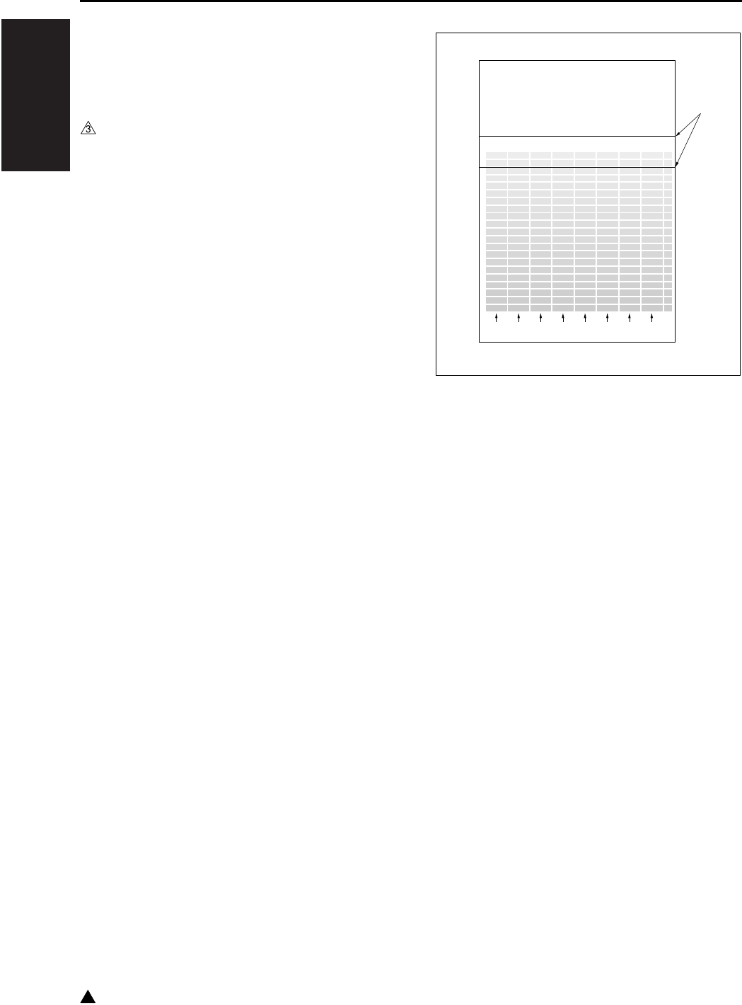
I ADJUSTMENT
36 MODE
1-48
3
9. Repeat the procedures 4 to 7 until the specified
value is attained.
10. Press the [RETURN] key to return to the “36
mode menu screen”.
8.7 LD2 Offset Adjustment
(7145 only)
The write position of the LD2 laser is adjusted.
This adjustment must be made when replacing the
write unit, drum and the developer.
Preparation: The drum cartridge must be set in
advance. The developing unit must be filled with
developer. The L detection adjustment, toner den-
sity adjustment, dot diameter adjustment and the
LD1 offset adjustment must be completed.
A. Procedure
1. Enter the 36 mode.
2. “36 mode menu screen”
Press the [1. Process adjustment] key.
3. Press the [Next item] key repeatedly until the
“LD2 offset adjustment” is displayed in the mes-
sage column.
4. “LD2 offset adjustment screen”
Press the [COPY] key.
5. Select A3 or 11 x 17 size paper, then press the
START button to print the test pattern.
6. Check the test patterns.
Specification: Check to see if the LD2 laser out-
put patterns are uniform as shown in the draw-
ing below and the starting points of the low
density section are matched between the refer-
ence lines.
7. If it is not within specification, press the # button
while holding down the ∗ button.
8. “LD2 offset adjustment screen”
Enter the offset value through the numeric keys
and press the [SET] key.
• Setting range: -128 ~ +127
9. Repeat the procedures 4 to 7 until the specified
value is attained.
10. Press the [RETURN] key to return to the “36
mode menu screen”.
[1] Reference line
LD1 LD2 LD1 LD2 LD1 LD2 LD1 LD2
[1]

I ADJUSTMENT
36 MODE
1-49
8.8 Timing Adjustment
This function adjusts each timing. When timing
adjustment is performed, use A3 or 11 x 17 size
paper.
A. Procedure
1. Select [2. Timing adj.] in the “36 mode menu
screen”.
The “Timing adjustment menu screen” will
appear.
• The following items are included in the timing
adjustment.
“1 Vertical/horizontal magnification adjustment”
“2 Restart timing adjustment”
“3 Paper feed loop amount adjustment”
“4 Leading edge original erasure amount adjust-
ment”
“5 Centering adjustment”
“6 Image read point adjustment”
“7 Restoring standard data”
2. Press the item key to be adjusted. The selected
setting screen will appear.
3. Press the [RETURN] key in each of the timing
adjustment screens to return to the “Timing
adjustment menu screen”.
8.8.1 Vertical/Horizontal magnification adjust-
ment
The vertical and horizontal magnifications of the
printer system and the copy system are adjusted.
A. Procedure
1. Select [2. Timing adj.] in the “36 mode menu
screen”.
The “Timing adjustment menu screen” will
appear.
2. Select the [1. Drum clock adj.] on the “Timing
adjustment menu screen”.
The “Drum clock adjustment (vertical/horizontal
magnification adjustment)” will appear.
3. This adjustment has the following items. These
can be selected by pressing the arrow key:
• Vertical magnification adjustment : Printer
• Vertical magnification adjustment : Printer 2
• Vertical magnification adjustment : Platen
• Horizontal magnification adjustment : Platen
• Vertical magnification adjustment : RADF (single
side, 50%)
• Vertical magnification adjustment : RADF (single
side, 100%)
• Vertical magnification adjustment : RADF (single
side, 200%)
• Vertical magnification adjustment : RADF (single
side, 400%)
• Vertical magnification adjustment : RADF (dou-
ble side, 50%)
• Vertical magnification adjustment : RADF (dou-
ble side, 100%)
• Vertical magnification adjustment : RADF (dou-
ble side, 200%)
• Vertical magnification adjustment : RADF (dou-
ble side, 400%)
4. Enter data from the numeric keys on the screen,
then press the [SET] key to enter the data that
have been entered.
5. Press the [COPY] key to return to the basic
screen, then make a test copy.
6. Press the # button while pressing the ∗ button to
return to the Vertical/Horizontal magnification
adjustment screen.
7. Press the [RETURN] key in the “Vertical and
horizontal magnification adjustment screen” to
return to the “Timing adjustment menu screen”.
(1) Printer vertical magnification adjustment
With the amount of the paper feed loop
adjusted properly between the registration
roller and the fixing roller, the transfer slippage
in the position about 20mm from the trailing
edge of the transfer paper is prevented.
a. Procedure
1. Enter the 36 mode.
2. “36 mode menu screen”
Press the [2. Timing adj.] key.
3. “Timing adjustment menu screen”
Press the [1. Drum clock adj.] key.
4. “Timing adjustment screen”
Press the arrow key until “Vertical magnification-
printer” appears in the message display area.
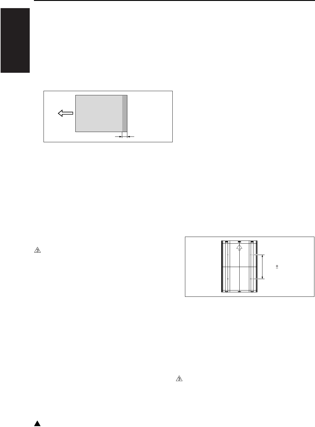
I ADJUSTMENT
36 MODE
1-50
3
5. “Vertical/horizontal magnification (drum clock)
adjustment screen”
Press the [COPY] key.
6. “Basic screen”
Set the copy size to A3 or 11 x 17, and the copy
quantity to 5, then press the START button and
output an test pattern (No. 9).
7. Output five sheets of paper, and check for trans-
fer jitter.
Check the transfer jitter at a point approx. 20mm
from the trailing edge of the paper.
8. If it is not within specification, press the # button
while holding down the ∗ button.
9. “Vertical/horizontal magnification (drum clock)
adjustment screen”
Enter a value through the numeric keys (the
change of a value should be made in two steps)
and press the [SET] key.
• Setting range: -50 (reduction) ~ +50 (enlarge-
ment)
1 step = 0.1%
10. Repeat steps 5 to 9 until the transfer jitter in all
five output sheets disappears.
11. Once you have confirmed that there is no trans-
fer jitter, press the arrow key, then select “Printer
2” to adjust the vertical magnification of “Printer
2”.
(2) Printer 2 vertical magnification adjustment
Adjust the vertical magnification of the printer
system.
Note:
• Ensure that the printer's vertical magnification is
adjusted before going ahead with this adjustment
a. Procedure
1. Enter the 36 mode.
2. “36 mode menu screen”
Press the [2. Timing adj.] key.
3. “Timing adjustment menu screen”
Press the [1. Drum clock adj.] key.
4. “Vertical/horizontal magnification (drum clock)
adjustment screen”
Press the arrow key until “Vertical magnification-
printer 2” appears in the message display area.
5. Press the [COPY] key.
6. “Basic screen”
Select A3 or 11 x 17 size paper, then press the
START button to print the test pattern.
7. Use a ruler to measure the vertical magnifica-
tion.
• Standard value: 0.5% max (life size)
Within ± 1mm with respect to 205.7mm
8. If it is not within specification, press the # button
while holding down the ∗ button.
9. “Vertical/horizontal magnification (drum clock)
adjustment screen”
Enter a value from the numeric keys, then press
the [SET] key.
• Setting range: -50 (reduction) ~ +50 (enlarge-
ment)
1 step = 0.1%
10. Repeat the procedures 5 to 9 until the specified
value is attained.
Approx.20mm
205.7 1
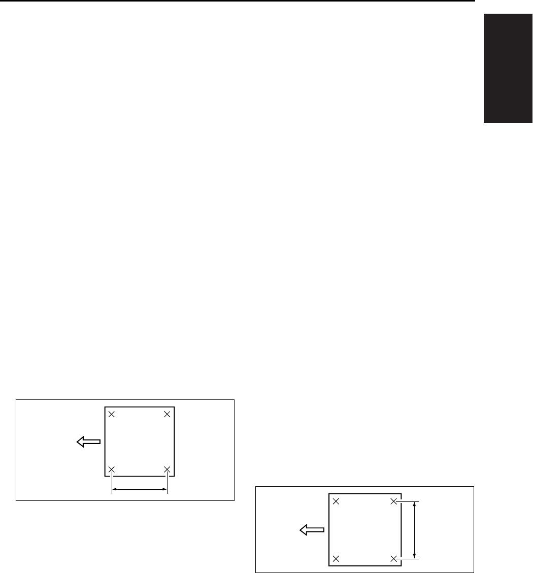
I ADJUSTMENT
36 MODE
1-51
11. Press the [RETURN] key to return to the “Timing
adjustment menu screen”.
(3) Platen vertical magnification adjustment
Adjust the vertical magnification of the scanner
system.
a. Procedure
1. Enter the 36 mode.
2. “36 mode menu screen”
Press the [2. Timing adj.] key.
3. “Timing adjustment menu screen”
Press the [1. Drum clock adj.] key.
4. “Vertical/horizontal magnification (drum clock)
adjustment screen”
Press the arrow key until “Vertical magnification-
platen” appears in the message display area.
5. Press the [COPY] key.
6. “Basic screen”
Set the new test chart on the original glass and
select A3 or 11 x 17 size paper. Then press the
START button.
7. Use a ruler to measure the vertical magnifica-
tion.
• Standard value: ± 0.5% max (life size)
Within ± 1mm with respect to 200mm
8. If it is not within specification, press the # button
while holding down the ∗ button.
9. “Vertical/horizontal magnification (drum clock)
adjustment screen”
Enter a value from the numeric keys, then press
the [SET] key.
• Setting range: -20 (reduction) ~ +20 (enlarge-
ment)
1 step = 0.05%
10. Repeat steps 5 to 9 until the vertical magnifica-
tion becomes the standard value.
11. Press the [RETURN] key to return to the “Timing
adjustment menu screen”.
(4) Platen horizontal magnification adjustment
Adjust the horizontal magnification of the copy
system.
Note:
• The result of the platen horizontal magnification
will be reflected all the images read by scanner
(RADF, platen).
a. Procedure
1. Enter the 36 mode.
2. “36 mode menu screen”
Press the [2. Timing adj.] key.
3. “Timing adjustment menu screen”
Press the [1. Drum clock adj.] key.
4. “Vertical/horizontal magnification (drum clock)
adjustment screen”
Press the arrow key until “Horizontal magnifica-
tion-platen” appears in the message display
area.
5. Press the [COPY] key.
6. “Basic screen”
Set the new test chart on the original glass and
select A3 or 11 x 17 size paper. Then press the
START button.
7. Use a ruler to measure the horizontal magnifica-
tion.
• Standard value: ± 0.5% max (life size)
Within ± 1mm with respect to 200mm
8. Press the # button while pressing the ∗ button to
return to the “Vertical/horizontal magnification
(drum clock) adjustment screen”.
9. “Vertical/horizontal magnification (drum clock)
adjustment screen”
Enter a value from the numeric keys, then press
the [SET] key.
200
200

I ADJUSTMENT
36 MODE
1-52
• Setting range: -10 (reduction) ~ +10 (enlarge-
ment)
1 step = 0.1%
10. Repeat steps 5 to 9 until the horizontal magnifi-
cation becomes the standard value.
11. Press the [RETURN] key to return to the “Timing
adjustment menu screen”.
(5) RADF vertical magnification adjustment
Adjust the vertical magnification while in RADF
copying.
a. Procedure
1. Enter the 36 mode.
2. “36 mode menu screen”
Press the [Timing adj.] key.
3. “Timing adjustment menu screen”
Press the [1. Drum clock adj.] key.
4. “Vertical/Horizontal magnification (drum clock)
adjustment screen”
Press the arrow key to select the magnification
you want to adjust.
The screen changes in the following order: Sin-
gle sided 50% → 100% → 200% → 400% →
Double sided 50% → 100% → 200% → 400%.
5. Press the [COPY] key.
6. Set the ADF adjustment chart on the RADF and
select A3 or 11 x 17 size paper. Then press the
START button.
7. Use a ruler to measure the vertical magnifica-
tion.
• Standard value: ± 0.5% max (life size)
Within ± 1.0mm with respect to 190mm
8. If it is not within specification, press the # button
while holding down the ∗ button.
9. “Vertical/Horizontal magnification (drum clock)
adjustment screen”
Enter a value from the numeric keys, then press
the [SET] key.
• Setting range: -20 (reduction) ~ +20 (enlarge-
ment)
1 step = 0.1%
10. Repeat steps 5 to 9 until the vertical magnifica-
tion becomes the standard value.
11. To adjust another adjustment item, press the
arrow key to select the desired adjustment.
12. Press the [RETURN] key to return to the “Timing
adjustment menu screen”.
8.8.2 Restart timing adjustment
To adjust the restart timing.
A. Procedure
1. Select the [2. Timing adj.] in the “36 mode menu
screen”, then the “Timing adjustment menu
screen” will appear.
2. Select the [2. Restart timing] on the “Timing
adjustment menu screen”. then the “Restart tim-
ing adjustment screen” will appear.
3. Using the arrow key will allow you to select the
following items.
• Restart timing adjustment : Engine (All)
• Restart timing adjustment : Engine (Main body
upper tray)
• Restart timing adjustment : Engine (Main body
lower tray)
• Restart timing adjustment : Engine (DB1)
• Restart timing adjustment : Engine (DB2)
• Restart timing adjustment : Engine (LCT)
• Restart timing adjustment : Engine (Bypass)
• Restart timing adjustment : Engine (ADU)
• Restart timing adjustment : RADF (single side)
• Restart timing adjustment : RADF (double side,
front)
• Restart timing adjustment : RADF (double side,
back)
4. Enter a desired value from the numeric keys on
the screen, then press the [SET] key to validate
your entry.
[1] Vertical magnification
[1]
190

I ADJUSTMENT
36 MODE
1-53
1
5. Turn on the Basic Screen by pressing the
[COPY] key, then make a test copy from the
basic screen.
6. Press the # button while pressing the ∗ button to
return to the “Horizontal/Vertical magnification
adjustment screen”.
7. Press the [RETURN] key in the “Restart timing
adjustment screen” to return to the “Timing
adjustment menu screen”.
(1) Engine restart timing adjustment
a. Procedure
1. Enter the 36 mode.
2. “36 mode menu screen”
Press the [2. Timing adj.] key.
3. “Timing adjustment menu screen”
Press the [2. Restart timing] key.
4. “Restart timing adjustment screen”
Press the arrow key until the desired adjustment
item appears in the message display area.
5. Press the [COPY] key.
6. “Basic screen”
Select a maximum paper size for the tray you
want to adjust and press START to output the
test pattern.
7. Check the restart timing.
• Standard value: ± 2.0mm max.
8. If it is not within specification, press the # button
while holding down the ∗ button.
9. “Restart timing adjustment screen”
Enter a value from the numeric keys, then press
the [SET] key.
• Setting range: -127 (slow) ~ +127 (fast)
1 step = 0.1mm
10. Repeat steps 5 to 9 until the restart timing
becomes the standard value.
11. To adjust another adjustment item, press the
arrow key to select the desired adjustment.
12. Press the [RETURN] key to return to the “Timing
adjustment menu screen”.
(2) RADF restart timing adjustment
Reference:
• The operation described here is the same as the
adjustment in “36 mode menu screen” - [9. RADF
adj.].
a. Procedure
1. Enter the 36 mode.
2. “36 mode menu screen”
Press the [2. Timing adj.] key.
3. “Timing adjustment menu screen”
Press the [2. Restart timing] key.
4. “Restart timing adjustment screen”
Press the arrow key until the desired RADF
adjustment item appears in the message display
area.
5. Press the [COPY] key.
6. “Basic screen”
Set the ADF adjustment chart on the RADF and
select A3 or 11 x 17 size paper. Then press the
START button.
• Adjustment the “RADF double side (second
side)”, then make a test copy in double side →
single side mode and check the restart timing of
2nd output paper.
7. Check the restart timing.
• Standard value: ± 3.0mm max. (life size)
8. If it is not within specification, press the # button
while holding down the ∗ button.
9. “Restart timing adjustment screen”
Enter a value from the numeric keys, then press
the [SET] key.
• Setting range: -50 (slow) ~ +50 (fast)
1 step = 0.1mm
10. Repeat steps 5 to 9 until the restart timing
becomes the standard value.
11. Press the [RETURN] key to return to the timing
adjustment menu screen.

I ADJUSTMENT
36 MODE
1-54
3
8.8.3 Paper feed loop amount adjustment
If a paper is skewed, adjust the amount of the loop
for each tray.
A. Procedure
1. Select the [2. Timing adj.] in the “36 mode menu
screen”, then the “Timing adjustment menu
screen” will appear.
2. Select the [3. Paper loop adj.] on the “36 mode
menu screen”, then the “Paper feed loop
amount adjustment screen” will appear.
3. Using the arrow key will allow you to select the
following items.
• Paper feed loop adjustment : All
• Paper feed loop adjustment : Main body upper
tray
• Paper feed loop adjustment : Main body lower
tray (small size) B5 only
• Paper feed loop adjustment : Main body lower
tray (large size) Other than B5
• Paper feed loop adjustment : DB upper tray
(small size) Other than A3, B4, 11 x 17 and 8.5 x
14.
• Paper feed loop adjustment : DB upper tray
(large size) A3, B4, 11 x 17 and 8.5 x 14
• Paper feed loop adjustment : DB lower tray
(small size) Other than A3 and 11 x 17
• Paper feed loop adjustment : DB lower tray
(large size) A3 and 11 x 17
• Paper feed loop adjustment : LCT
• Paper feed loop adjustment : Bypass (normal
paper)
• Paper feed loop adjustment : Bypass (thick
paper)
• Paper feed loop adjustment : Bypass (post card)
• Paper feed loop adjustment : ADU (excepting
8.5 x 5.5)
• Paper feed loop adjustment : ADU (8.5 x 5.5)
• Paper feed loop adjustment : RADF (single side)
4. Enter a desired value from the numeric keys on
the screen, then press the [SET] key to validate
your entry.
5. Turn on the Basic Screen by pressing the
[COPY] key, then make a test copy from the
basic screen.
6. Press the # button while pressing the ∗ button to
return to the “Paper feed loop quantity adjust-
ment screen”.
7. Press the [RETURN] key in the “Paper feed loop
quantity adjustment screen” to return to the
“Timing adjustment menu screen”.
(1) Paper feed loop adjustment for engine
a. Procedure
1. Enter the 36 mode.
2. “36 mode menu screen”
Press the [2. Timing adj.] key.
3. “Timing adjustment menu screen”
Press the [3. Paper loop adj.] key.
4. “Paper feed loop amount adjustment screen”
Press the arrow key until the desired adjustment
item appears in the message display area.
5. Press the [COPY] key.
6. “Basic screen”
Select a tray and a paper size properly and
press START to output the test pattern.
7. Check the skewing condition.
8. When the paper feed loop quantity is not appro-
priate, press the # button while pressing the ∗
button.
9. “Paper feed loop amount adjustment screen”
Enter a value from the numeric keys, then press
the [SET] key.
• Setting range: -100 ~ +15
1 step = 0.23mm
10. Repeat steps 5 to 9 until the paper feed loop
amount becomes appropriate.
11. Press the [RETURN] key to return to the “Timing
adjustment menu screen”.

I ADJUSTMENT
36 MODE
1-55
1
(2) Paper feed loop adjustment for RADF
Reference:
• The operation described here is the same as the
adjustment in “36 mode menu screen” - [9. RADF
adj.].
a. Procedure
1. Enter the 36 mode.
2. “36 mode menu screen”
Press the [2. Timing adj.] key.
3. “Timing adjustment menu screen”
Press the [3. Paper loop adj.] key.
4. “Paper feed loop amount adjustment screen”
Press the arrow key until “RADF” appears in the
message display area.
5. Press the [COPY] key.
6. “Basic screen”
Set the ADF adjustment chart on the RADF and
select A3 or 11 x 17 size paper. Then press the
START button.
7. Check the condition of skewing in the output
copy.
8. When the paper feed loop quantity is not appro-
priate, press the # button while pressing the ∗
button.
9. “Paper feed loop amount adjustment screen”
Enter a value from the numeric keys, then press
the [SET] key.
• Setting range: -10 (small) ~ +10 (large)
1 step = 0.5mm
10. Repeat steps 5 to 9 until the skewing condition
is correct.
11. Press the [RETURN] key to return to the “Timing
adjustment menu screen”.
8.8.4 Leading edge original erasure adjustment
Adjust the leading edge original erasure (leading
edge blank cut) amount.
Note:
• If you reduce the erasure width, a black line may
appear on the leading edge of the paper when
you make an enlarged copy.
A. Procedure
1. Enter the 36 mode.
2. “36 mode menu screen”
Press the [2. Timing adj.] key.
3. “Timing adjustment menu screen”
Press the [4. Lead edge timing] key.
4. “Leading edge original erasure adjustment
screen”
Press the [COPY] key.
5. “Basic screen”
Place the test chart on the platen glass. Select a
maximum paper size for the tray you want to
adjust and press START.
6. Measure the leading edge original erasure.
• Standard value: Within 3.0mm
7. If it is not within specification, press the # button
while holding down the ∗ button.
8. “Leading edge original erasure adjustment
screen”
Enter a value from the numeric keys, then press
the [SET] key.
• Setting range: -20 (small) ~ +20 (large)
1 step = 0.1mm
9. Repeat steps 4 to 8 until the leading edge origi-
nal erasure amount becomes the standard
value.
10. Press the [RETURN] key to return to the “Timing
adjustment menu screen”.

I ADJUSTMENT
36 MODE
1-56
8.8.5 Centering adjustment
In the centering adjustment, the centering of the
image is adjusted in the direction at a right angle to
the feed direction.
A. Procedure
1. Select the [2. Timing adj.] in the “36 mode menu
screen”, then the “Timing adjustment menu
screen” will appear.
2. Select the [5. Centring adj.] on the “Timing
adjustment menu screen”, then the centering
adjustment screen will appear.
3. Using the arrow key will allow you to select the
following items.
(1) Each of tray adjustments
• Centering adjustment : All
• Centering adjustment : Main body upper tray
(common, small size, large size)
• Centering adjustment : Main body lower tray
(common, small size, large size)
• Centering adjustment : DB upper tray
(common, small size, large size)
• Centering adjustment : DB lower tray
(common, small size, large size)
• Centering adjustment : LCT
• Centering adjustment : ADU
(common, small size, large size)
• Centering adjustment : Bypass
(common, small size, large size)
(2) Platen adjustment
• Centering adjustment : Platen
(3) RADF adjustment
• Centering adjustment : RADF
(single side, double side front, double side back)
4. Enter a desired value from the numeric keys on
the screen, then press the [SET] key to validate
your entry.
5. Turn on the Basic Screen by pressing the
[COPY] key, then make a test copy from the
basic screen.
6. Press the # button while pressing the ∗ button to
return to the centering adjustment screen.
7. Press the [Preceding screen] key in the “Center-
ing adjustment screen” to return to the “Timing
adjustment menu screen”.
(1) Each tray centering adjustment
a. Procedure
1. Enter the 36 mode.
2. “36 mode menu screen”
Press the [2. Timing adj.] key.
3. “Timing adjustment menu screen”
Press the [5. Centring adj.] key.
4. “Centering adjustment screen”
Press the arrow key until the desired tray
appears in the message display area.
5. Press the [COPY] key.
6. “Basic screen”
Select A3 or 11 x 17 size paper, then press the
START button to print the test pattern.
7. Fold the output at the center in the paper feed
direction, and check that the left and right lines
overlap completely.
• Standard value: Within ± 2mm
8. If it is not within specification, press the # button
while holding down the ∗ button.
9. “Centering adjustment screen”
Enter a value from the numeric keys, then press
the [SET] key.
• Setting range: -53 (inward direction of the center
line) ~ +53 (rear direction of the center line)
1 step = 0.09mm
10. Repeat steps 5 to 9 until the miscentering is
within standard value.
Note:
• If it can not be adjusted within the specified
range, see “Other Adjustments”.
11. To adjust another adjustment item, press the
arrow key to select the desired adjustment.
12. Press the [RETURN] key to return to the “Timing
adjustment menu screen”.
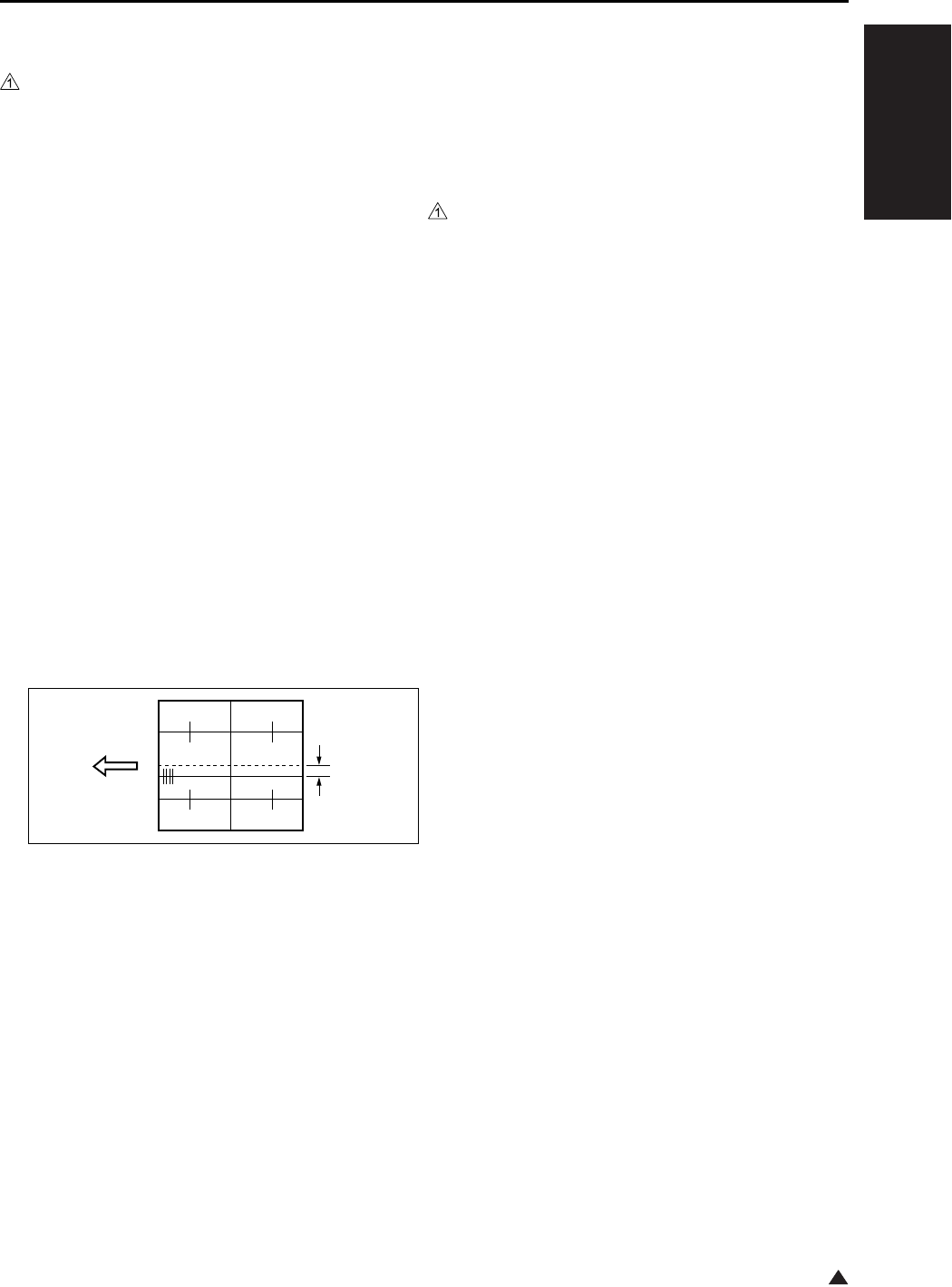
I ADJUSTMENT
36 MODE
1-57
1
(2) ADU centering adjustment
Note:
• Be sure to perform the centering adjustment for
each tray before starting this adjustment.
a. Procedure
1. Enter the 36 mode.
2. “36 mode menu screen”
Press the [2. Timing adj.] key.
3. “Timing adjustment menu screen”
Press the [5. Centring adj.] key.
4. “Centering adjustment screen”
Press the arrow key until “ADU” appears in the
message display area.
5. Press the [COPY] key.
6. “Basic screen”
Select copy mode to single side → double side
mode, then press the START button to print the
test pattern.
7. Fold the output at the center in the paper feed
direction, and check that the left and right lines
overlap completely.
• Standard value: Back : Within ± 3mm
Front and back : Within ± 3mm
8. If it is not within specification, press the # button
while holding down the ∗ button.
9. “Centering adjustment screen”
Enter a value from the numeric keys, then press
the [SET] key.
• Setting range: -53 (inward direction of the center
line) ~ +53 (rear direction of the center line)
1 step = 0.09mm
10. Repeat steps 5 to 9 until the miscentering is
within standard value.
11. To adjust another adjustment item, press the
arrow key to select the desired adjustment.
12. Press the [RETURN] key to return to the “Timing
adjustment menu screen”.
(3) Platen centering adjustment
Note:
• Be sure to perform the centering adjustment for
each tray before starting this adjustment.
a. Procedure
1. Enter the 36 mode.
2. “36 mode menu screen”
Press the [2. Timing adj.] key.
3. “Timing adjustment menu screen”
Press the [5. Centring adj.] key.
4. “Centering adjustment screen”
Press the arrow key until “Platen” appears in the
message display area.
5. Press the [COPY] key.
6. “Basic screen”
Set the new test chart on the original glass and
select A3 or 11 x 17 size paper, then press the
START button.
7. Check the miscentering by comparing the origi-
nal with the copy.
• Standard value: Within ± 2mm
8. If it is not within specification, press the # button
while holding down the ∗ button.
9. “Centering adjustment screen”
Enter a value from the numeric keys, then press
the [SET] key.
• Setting range: -74 (inward direction of the center
line) ~ +74 (rear direction of the center line)
1 step = 0.04mm
10. Repeat steps 5 to 9 until the miscentering is
within standard value.
11. Press the [RETURN] key to return to the “Timing
adjustment menu screen”.
[1] Lengthwise direction
[2] Miscentering amount between first side
and second side
[1]
[2]

I ADJUSTMENT
36 MODE
1-58
1
(4) RADF centering adjustment
Note:
• Be sure to perform the centering adjustment for
each tray before starting this adjustment.
a. Procedure
1. Enter the 36 mode.
2. “36 mode menu screen”
Press the [2. Timing adj.] key.
3. “Timing adjustment menu screen”
Press the [5. Centring adj.] key.
4. “Centering adjustment screen”
Press the arrow key until “RADF” appears in the
message display area.
5. Press the [COPY] key.
6. “Basic screen”
Set the ADF adjustment chart on the RADF and
select A3 or 11 x 17 size paper, then press the
START button.
• Adjust the “RADF (double side (second side))”,
then make a test copy in double side → single
side mode and check the loop amount of 2nd
outputted paper.
7. Check the miscentering by comparing the origi-
nal with the copy.
• Standard value: Within ± 3mm
8. If it is not within specification, press the # button
while holding down the ∗ button.
9. “Centering adjustment screen”
Enter a value from the numeric keys, then press
the [SET] key.
• Setting range: -74 (inward direction of the center
line) ~ +74 (rear direction of the center line)
1 step = 0.04mm
10. Repeat steps 5 to 9 until the miscentering is
within standard value.
11. Press the [RETURN] key to return to the “Timing
adjustment menu screen”.
8.8.6 Image read point adjustment
Adjust the image read point (leading edge timing).
For the image read position adjustment, the follow-
ing two types are available:
• Platen adjustment
• RADF adjustment
Note:
• Be sure to perform the restart timing adjustment
(engine) before starting this adjustment.
• The RADF read position adjustment is inhibited in
the field.
• If you shift this value by a large amount, the
RADF read density may change.
A. Procedure
1. Enter the 36 mode.
2. “36 mode menu screen”
Press the [2. Timing adj.] key.
3. “Timing adjustment menu screen”
Press the [6. Read point adj.] key.
4. “Image read point adjustment screen”
Select the “Platen adjustment”, and press the
[COPY] key.
5. “Basic screen”
Set the new test chart on the original glass and
select A3 or 11 x 17 size paper, then press the
START button.
6. Make a comparison between original image and
test copy image. Then check the image read
point.
• Standard value: 10 ± 1.0mm
7. If it is not within specification, press the # button
while holding down the ∗ button.
8. “Image read point adjustment screen”
Enter a value from the numeric keys, then press
the [SET] key.
• Setting range: -20 (small) ~ +20 (large)
1 step = 0.1mm
9. Repeat steps 5 to 9 until the image read point is
within standard value.
10. Press the [RETURN] key to return to the “Timing
adjustment menu screen”.

I ADJUSTMENT
36 MODE
1-59
8.8.7 Recall standard data
Reset the adjusted set values of timing adjustment
to the standard values (factory default data).
The following are included in the return to standard
data:
• Recall standard data : Vertical/Horizontal magni-
fication adjustment
• Recall standard data : Restart timing adjustment
• Recall standard data : Paper feed loop amount
adjustment
• Recall standard data : Leading edge original era-
sure adjustment
• Recall standard data : Centering adjustment
• Recall standard data : Original read point adjust-
ment
A. Procedure
1. Enter the 36 mode.
2. “36 mode menu screen”
Press the [2. Timing adj.] key.
3. “Timing adjustment menu screen”
Press the [7. Factory default] key.
4. “Resetting standard data screen”
Press the arrow key until the desired item
appears in the message display area.
5. Press the [YES] key to reset the set values to
the standard values that have been selected
and to return to the “Timing adjustment menu
screen”. Press the [NO] or [RETURN] key, then
the set values are not reset and return to the
“Timing adjustment menu screen”.
6. To reset another adjustment item, repeat steps
4 to 5.
7. Press the [RETURN] key to return to the “Timing
adjustment menu screen”.
8.9 Running Test Mode
Conduct a test while in continuous copying opera-
tion.
Select the [3. Running mode] in the “36 mode menu
screen”, then the “Running test mode menu screen”
will appear.
The following items can be selected:
A. Intermittent copy mode
In this mode, after the set number of copy oper-
ations has been completed, the machine goes
into the copy ready status, waits 0.5 sec., then
starts the same operation again.
B. Paperless intermittent copy mode
It makes copies at roughly the same timing as
for a normal copy, without performing paper
detection or jam detection. Also, like running
mode 1, after the set number of copy opera-
tions has been completed, the machine goes
into the copy ready status, waits 0.5 sec., then
starts the same operation again.
C. Paperless mode
It makes copies at roughly the same timing as
for a normal copy, without performing paper
detection or jam dection.
D. Paperless/endless mode
It automatically sets the copy quantity to infinity.
Also, like running mode 3, it makes copies at
roughly the same timing as for a normal copy,
without performing paper detection or jam
detection.
E. Running mode
Running mode consists of paperless/endless
mode plus an operation consisting of an optics
each time scan and an automatic paper feed
tray change.

I ADJUSTMENT
36 MODE
1-60
3
8.9.1 Setting method
A. Procedure
1. Enter the 36 mode.
2. “36 mode menu screen”
Press the [3. Running mode] key.
3. “Running test mode menu screen”
Press the key according to the desired mode.
(Mode 1 to Mode 5)
4. “Basic screen”
Press the START button.
5. After checking the copy operation, press the
Stop button to stop copy operation.
6. Press the # button while pressing the ∗ button to
return to the “Running mode menu screen”.
7. To perform another running test mode, repeat
steps 3 to 6.
8. Press the [RETURN] key to return to “36 mode
menu screen”.
8.10 Test Pattern Output
Output various test patterns and use the results to
detach defective parts.
Select the [4. Test pattern] in the “36 mode menu
screen”, then the test pattern output screen will
appear.
Note:
• For modes not listed specifically on the Service
Manual, output should not be made.
A. Procedure
1. Enter the 36 mode.
2. “36 mode menu screen”
Press the [4. Test pattern] key.
3. “Test pattern output screen”
Enter a pattern number to be output from
numeric key.
4. Press the [COPY] key.
5. “Copy screen”
Select A3 or 11 x 17 and press the start button
to output a test pattern.
6. When you want to output another test pattern,
press the # button while pressing the ∗ button
and repeat the procedures 3 to 5 above.
7. Press the [RETURN] key to return to the “36
mode menu screen”.

I ADJUSTMENT
36 MODE
1-61
No.1 Overall Halftone
[Check Items]
• When the density is set to 70 (halftone)
When there are white stripes, black stripes or uneven density found, check the printer system for any
abnormality.
[Recommended checkpoints]: Developing unit, and cleaning unit
• When the density is set to 0 (white)
When there is image gray back ground, check the printer system for any abnormality.
[Recommended checkpoints]: Charging corona, and high voltage contact
• When the density is set at 255 (black)
When the density is thin, check the printer system for any abnormality.
[Recommended check point]: Write unit
* For information about setting the density, see “7.11 Test pattern density adjustment” below.
Test Pattern
When the density is set to 70 When the density is set to 0 When the density is set to 255
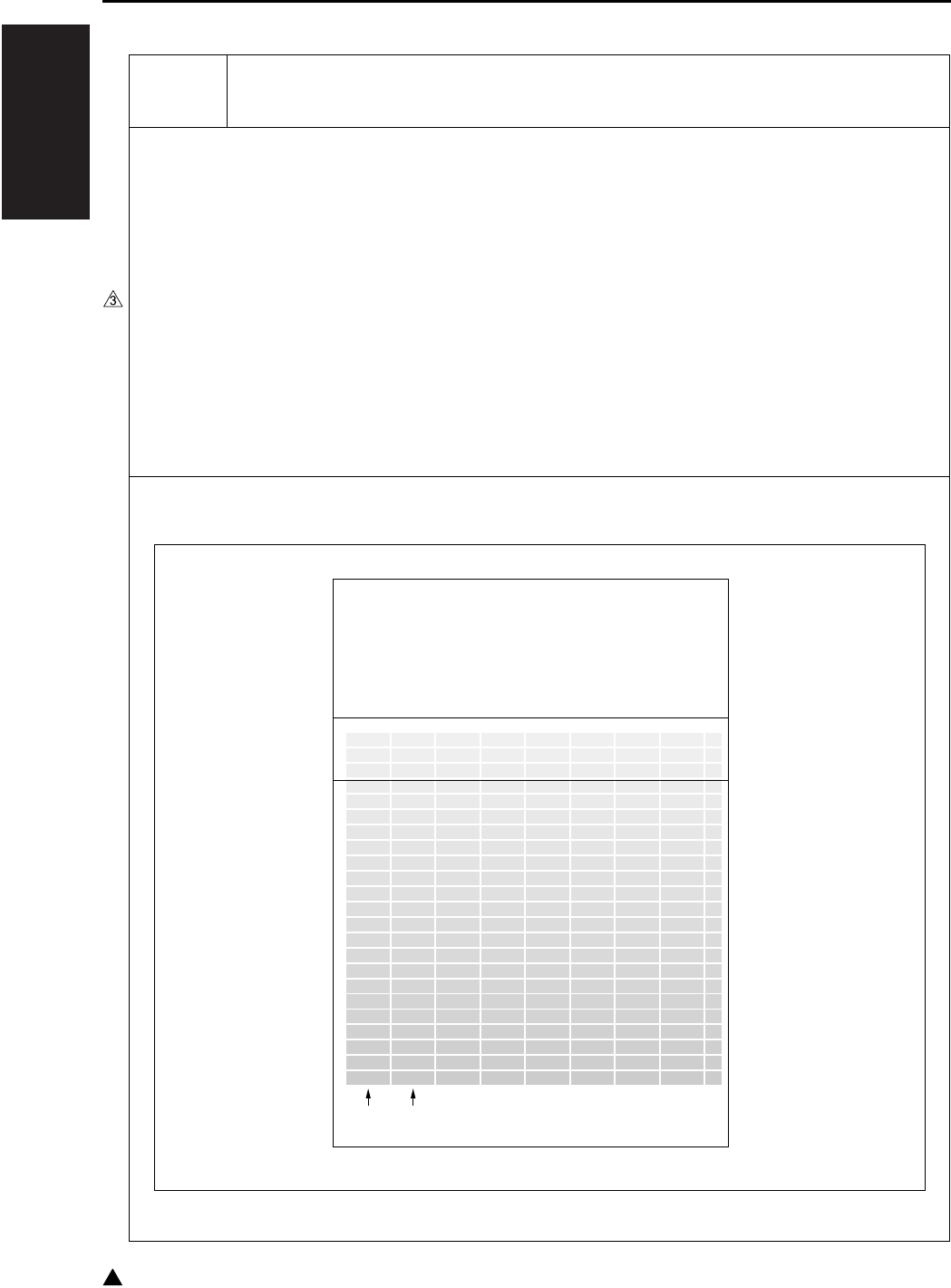
I ADJUSTMENT
36 MODE
1-62
3
No.5 Gradation Pattern
[Check Items]
• Check the pattern to see if the laser output of LD1/LD2 is uniform with the gradation continuously repro-
duced.
[Recommended checkpoints]: Write unit, and LD1/LD2 offset adjustment
*For LD1/LD2 offset adjustment, see “1. Process adjustment”.
*Since a single beam is employed for 7235/7228/7222, the pattern shown as LD2 in the illustration
below is also output by LD1.
Test Pattern
LD1 LD2
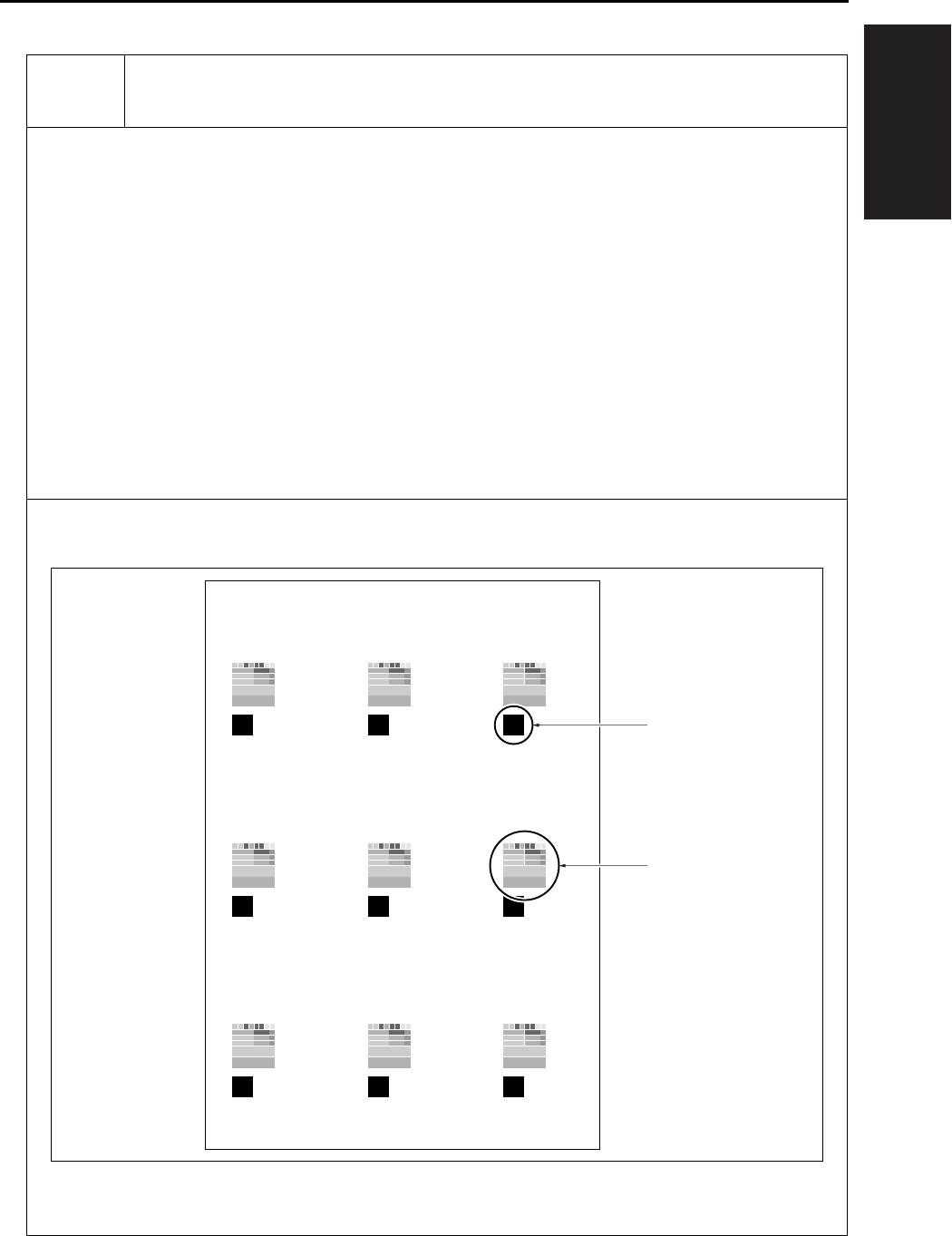
I ADJUSTMENT
36 MODE
1-63
No.11 Beam Check
[Check Items 1]
• For developement and analysis of the write unit
[Check Items 2]
• Check the solid black pattern to see if there is uneven density found in the main scanning and sub-scan-
ning directions.
[Recommended checkpoints]: Charging corona, transfer/separation corona unit, and developing unit
[Check Items 3]
• Check to see if there is any image repelling in the gradation pattern at the leading/trailing edge of the
test pattern in the feed direction.
[Recommended checkpoint]: Transfer/separation corona unit
Test Pattern
[1] Solid black pattern [2] Gradation pattern
[2]
[1]
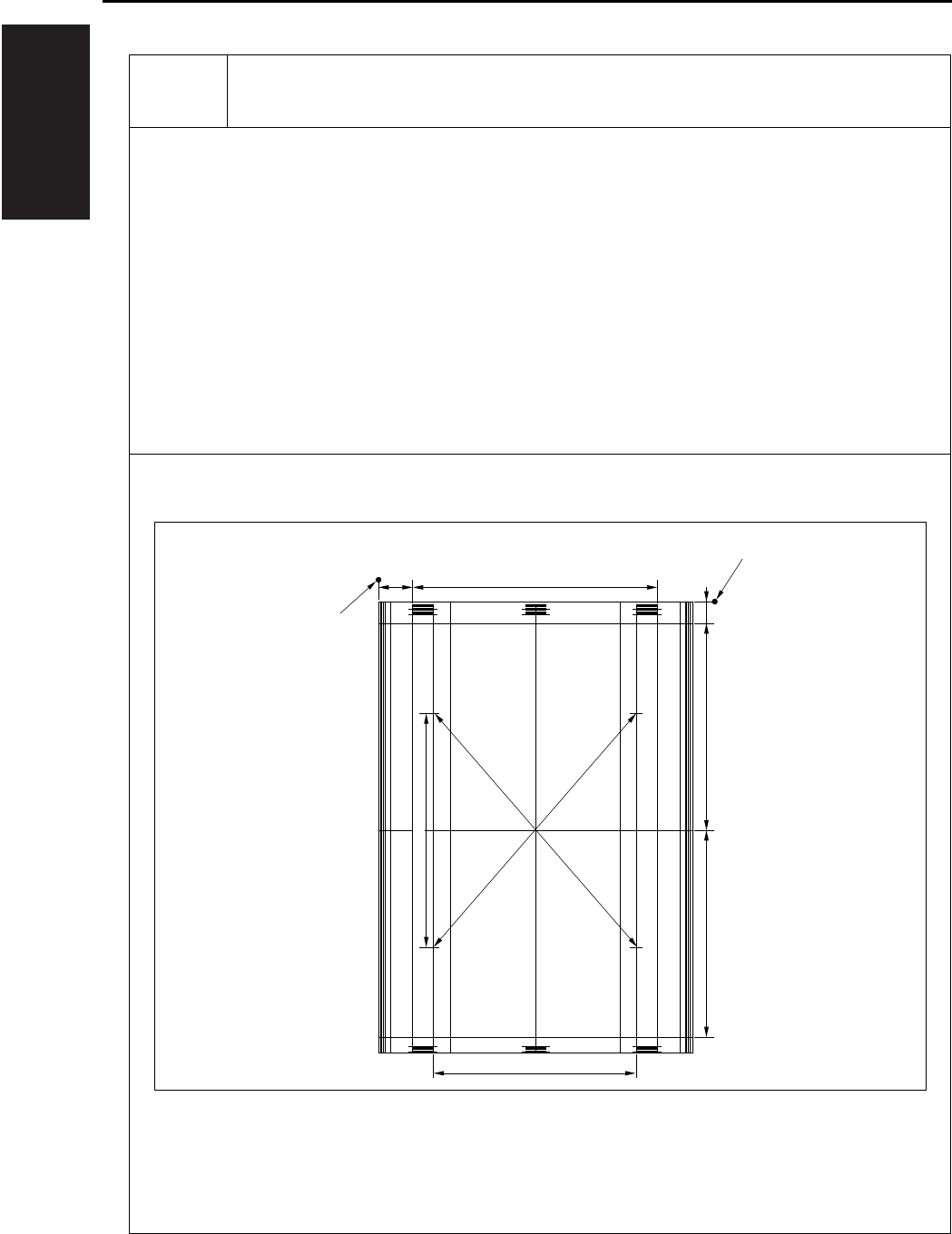
I ADJUSTMENT
36 MODE
1-64
No.16 Linearity Evaluation Pattern
[Check Items]
Judge from this test pattern which of the scanner system and the printer system is abnormal.
Items that can be checked include horizontal magnification, vartical magnification, tilt image, and lead-
ing edge timing of the printer system. If the copy image is defective despite no abnormality being visible
on the test pattern, the scanner system is defective.
Test Pattern
[1] Edge of pager
31mm 237mm
190mm
20mm
190mm190mm
280mm
280mm
205.7mm
[1]
[1]

I ADJUSTMENT
36 MODE
1-65
8.11 Test Pattern Density Adjust-
ment
Density of respective patterns is adjusted in the fol-
lowing procedure.
A. Procedure
1. Enter the 36 mode.
2. “36 mode menu screen”
Press the [5. Density adj.] key.
3. “Print density adjustment menu screen”
Press the [1. Print density adj. (1)] Key.
4. “Print density adjustment screen”
Press the key according to the desired test pat-
tern to be adjusted.
5. Enter a desired density by a numeric value from
the numeric keys, then press the [SET] key.
Input range : 000 (light) to +255 (dark).
6. Press the [COPY] key.
7. “Basic screen”
Press the START button to output a test pattern.
8. Check the density of the output test pattern.
9. Press the # button while pressing the ∗ button to
return to the “Print density adjustment screen”.
10. To adjust another test pattern, repeat steps 4 to
9.
11. Press the [RETURN] key to return to “Print den-
sity adjustment menu screen”.
8.12 Image Quality Adjustment
This function adjusts the image quality adjustment.
The following are shown on the image quality
adjustment menu:
• RADF scan density adj.
• Non-image area erase check.
8.12.1 RADF scanning density adjustment
When the slit glass is replaced, adjust the density
when reading the original with the RADF.
Note:
• The mechanical adjustment, optical adjustment
and electrical adjustment of the scanner are com-
pleted.
• Make sure that the slit glass is cleaned.
• Make sure that the white chart is not dirty or
folded.
A. Procedure
1. Enter the 36 mode.
2. “36 mode menu screen”
Press the [6. Image quality adj] key.
3. “Image quality adjustment screen”
Press the [1. RADF Scan density adj.] key.
4. “RADF Scanning density adjustment screen”
Set the white chart in A4 direction on the RADF.
5. Press the [START] key.
6. Check that “Completed” appears in the mes-
sage display area.
7. If “ERROR” appears in the message display
area, then repeat steps 4 and 5.
Note:
• If “ERROR” is displayed repeatedly, there is a
possibility of a defect in the adjustment of the
scanner machine, optics, or electricrelated parts.
8. Press the [RETURN] key to return to the “Image
quality adjustment screen”.

I ADJUSTMENT
36 MODE
1-66
8.12.2 Non-image area erase check
Carry out a survey of the installation environment
after the machine is newly installed or moved to a
different location.
Preparation:
• Be sure that the RADF is fully open.
• Do not place anything on the platen glass.
• The platen glass must not be dirty.
A. Procedure
1. Enter the 36 mode.
2. “36 mode menu screen”
Press the [6. Image quality adj] key.
3. “Image quality adjustment screen”
Press the [2. Non-image Area Erase check] key.
4. “Non-image area erase check screen”
Press the [START] key.
5. Confirm that “Operation OK” appears on the
message display.
If “Operation NG” appears, carry out non-origi-
nal erasure installation survey once again while
seeing to “Trouble and Remedy” below.
6. Press the [RETURN] key to return to the “Image
quality adjustment screen”.
B. <Trouble and Remedy>
(1) Warning-1
Adjust for Extreme Brightness. In many cases, the
Nonimage-area-erase function will not operate cor-
rectly.
Please confirm “adjustment” - “36 mode” columns of
the Service Manual.
(2) Remedy-1
If you use the non-original erasure function, or copy
originals that have a dark background using the
nonoriginal erasure method, relatively infrequently,
use the machine in its present installation environ-
ment.
If, however, you copy originals that have a dark
background fairly frequently, re-install the machine
in a dark location and facing a direction such that
external light does not get into it, then carry out the
installation survey once again.
(3) Warning-2
A datum with potentioal not to function non-imagea-
rea-erase is found.
Please confirm “adjustment” - “36 mode” columns of
the Service Manual.
(4) Remedy-2
If you use the non-original erasure function rela-
tively infrequently, you can use the machine in its
present installation environment.
If, however, you copy originals that have a dark
background fairly frequently, reinstall the machine in
a dark location and facing a direction such that
external light does not get into it, then carry out the
installation survey once again. In this case, if there
is a bright light source, such as a fluorescent light,
directly above the machine, reconsider the installa-
tion location and direction, or take steps to block off
the light from the light source (by using a cover, for
example), then carry out the installation survey
once again.

I ADJUSTMENT
36 MODE
1-67 3
8.13 List Print
Select the [7. List Print] from the “36 mode menu
screen” to display the list print menu screen.
You can select following menu options from this
screen.
• Test pattern
• Font pattern
• Memory dump list
• Management list
• Adjustment list
• Log list (1)
• Log list (2)
• Analysing list
• E-Mail KRDS com.list
Note:
• Don't try to touch a mode not mentioned.
A. Test pattern
This option is used to output a grid pattern con-
sisted of line width of 2 dots and line-to-line
space of 500 dots. From this pattern, you can
check the write system for normal performance.
B. Font pattern
This option outputs the font list built in the
engine.
C. Memory dump list
This option is used to dump out data (in HEX
and ASCII format) after the address specified in
E-RDH memory (this list is referenced for trou-
bleshooting).
D. Management list
This option outputs the machine status, counter
information and history of jam and so on.
E. Adjustment list
This option outputs a list of current adjusting
values in the 25/36 mode.
F. Log list (1)
The data from the memory is dumped in the
HEX format and the ASCII format. (for analyz-
ing trouble)
Normally not used.
G. Log list (2)
The data from the memory is dumped in the
HEX format and the ASCII format. (for analyz-
ing trouble)
Normally not used.
H. Analysing list
Outputs the necessary list prints together if
trouble occurs in the field. (for analysing trou-
ble)
Normally not used.
(1) Procedure
1. Enter the 36 mode.
2. “36 mode menu screen”
Press the [7. List print] key.
3. “List print menu screen”
Press the key corresponding to the desired
menu option.
4. “List print screen”
When outputting the memory dump list, specify
the start and end addresses.
Note:
• The memory dump list is dump output in both the
HEX and ASCII format.
5. Press the [COPY] key.
6. “Basic screen”
Press the [START] key to output the list.
7. Press the # button while depressing the ∗ button
to return to the list print screen.
8. When outputting another list, repeat above
steps 3 to 7.
9. Press the [RETURN] key to return to the list
print menu screen.
I. E-Mail KRDS com.list
This option outputs the result of the E-mail
KRDS communication.

I ADJUSTMENT
36 MODE
1-68
8.14 Counter Clear
The counter must be cleared whenever the drum or
fixing parts/unit is replaced.
Select the [8. Counter Clear] from the 36 mode
menu screen to display the counter clear screen.
Following menu options are available from this
screen.
• Drum related counter (Drum counter, Drum drive
counter).
• Fixing counter (Fixing web counter).
A. Procedure
1. Enter the 36 mode.
2. “36 mode menu screen”
Press the [8. Counter clear] key.
3. “Counter clear screen”
Press the key corresponding to the item to be
cleared.
4. Message in the message display area will con-
firm if you really want to clear the item. Press
the [YES] key. When the item is cleared, the
“Counter clear screen” will be restored.
5. When clearing another counter, repeat above
steps 3 and 4.
6. Press the [RETURN] key to return to “36 mode
menu screen”.
Reference:
• The operation here is the same as [2. PM count] -
[3. Counter clear] on the “25 mode menu screen”.
8.15 Adjustment of RADF
Adjustments of RADF are performed in the follow-
ing procedures. For the adjustment, A3 or 11 x 17
copy paper should be used.
A. Procedure
1. Select the [9. RADF adj.] from the “36 mode
menu screen” to display the RADF adjustment
menu.
The following are included in the RADF adjust-
ment:
“1 Vertical/horizontal magnification (Drum clock)
adjustment”
“2 Restart timing adjustment”
“3 Paper feed loop amount adjustment”
“4 Centering adjustment”
“5 RADF scanning density adjustment”
2. Press the key corresponding to the desired
item. The screen corresponding to the selected
item will appear.
3. Press the [Preceding screen] key in each of the
RADF adjustment screens to return to the
“RADF adjustment menu screen”.
8.15.1 Vertical magnification adjustment in
RADF system
Adjust the vertical magnification of the RADF.
A. Procedure
1. Select the [9. RADF adj.] from the “36 mode
menu screen” to display the “RADF adjustment
menu”.
2. Select [1. Drum clock adj.] from the “RADF
adjustment menu” and the “Magnification
screen” will appear.
3. Using the arrow key will allow you to select the
following items.
• Vertical magnification adjustment : RADF (single
side, 50%)
• Vertical magnification adjustment : RADF (single
side, 100%)
• Vertical magnification adjustment : RADF (single
side, 200%)
• Vertical magnification adjustment : RADF (single
side, 400%)

I ADJUSTMENT
36 MODE
1-69
• Vertical magnification adjustment : RADF (dou-
ble side, 50%)
• Vertical magnification adjustment : RADF (dou-
ble side, 100%)
• Vertical magnification adjustment : RADF (dou-
ble side, 200%)
• Vertical magnification adjustment : RADF (dou-
ble side, 400%)
4. Enter a desired value from the numeric keys on
the screen, then press the [SET] key to validate
your entry.
5. Turn on the Basic Screen by pressing the
[COPY] key, then make a test copy from the
basic screen.
6. Press the # button while depressing the ∗ button
to return to the “Magnification adjustment
screen”.
7. Press the [Preceding screen] key in the “Verti-
cal/horizontal magnification adjustment screen”
to return to the “RADF adjustment menu
screen”.
B. Vertical magnification adjustment in RADF
system
Adjust the vertical magnification while in RADF
copying.
a. Procedure
1. Enter the 36 mode.
2. “36 mode menu screen”
Press the [9. RADF adj.] key.
3. “RADF adjustment menu screen”
Press the [1. Drum clock adj.] key.
4. “Vertical/Horizontal magnification (drum clock)
adjustment screen”
Press the arrow key to select the magnification
you want to adjust.
The screen changes in the following order: Sin-
gle sided 50% → 100% → 200% → 400% →
Double sided 50% → 100% → 200% → 400%.
5. Press the [COPY] key.
6. Set the ADF adjustment chart on the RADF and
select A3 or 11 x 17 size paper. Then press the
START button.
7. Use a ruler to measure the vertical magnifica-
tion.
• Standard value: ± 0.5% max (life size)
Within ± 1.0mm with respect to 190mm
8. If it is not within specification, press the # button
while holding down the ∗ button.
9. “Vertical/Horizontal magnification (drum clock)
adjustment screen”
Enter a value from the numeric keys, then press
the [SET] key.
• Setting range: -20 (reduction) ~ +20 (enlarge-
ment)
1 step = 0.1%
10. Repeat steps 5 to 9 until the vertical magnifica-
tion becomes the standard value.
11. To adjust another adjustment item, press the
arrow key to select the desired adjustment.
12. Press the [RETURN] key to return to the “RADF
adjustment menu screen”.
8.15.2 Adjustment of restart timing
Use the following procedure to adjust the RADF
restart timing.
A. Procedure
1. Select the [9. RADF adj.] from the “36 mode
menu screen” to display the “RADF adjustment
menu”.
2. Select [2. Restart timing] from the “RADF
adjustment menu” and the “Re-start timing
adjustment screen” will appear.
[1] Vertical magnification
[1]
190

I ADJUSTMENT
36 MODE
1-70
1
3. Using the arrow key will allow you to select the
following items.
• Restart timing adjustment : RADF (single side)
• Restart timing adjustment : RADF (double side,
front)
• Restart timing adjustment : RADF (double side,
back)
4. Enter a desired value from the numeric keys on
the screen, then press the [SET] key to validate
your entry.
5. Turn on the Basic Screen by pressing the
[COPY] key, then make a test copy from the
basic screen.
6. Check the restart timing.
Standard value: -3.0mm maximum (Life size).
7. If it is not within specification, press the # button
while depressing the ∗ button
8. “Restart timing adjustment screen”
Enter the value from the numeric keys, then
press the [SET] key.
• Setting range: -50 (delays the timing) ~
+50 (advances the timing)
1 step = 0.1mm
9. Repeat steps 5 to 9 until the re-start timing
meets the standard value.
10. Press the [RETURN] key in the “Restart timing
adjustment screen” to return to the “RADF
adjustment menu screen”.
8.15.3 Paper feed loop adjustment
Reference:
• The operation described here is the same as the
adjustment in “36 mode menu screen” -[2. Timing
adjustment].
Adjust the paper feed loop quantity while in RADF
copying.
A. Procedure
1. Enter the 36 mode.
2. “36 mode menu screen”
Press the [9. RADF adj.] key.
3. “RADF adjustment menu screen”
Press the [3. Paper Loop adj.] key.
4. “Paper feed loop amount adjustment screen”
Press the [COPY] key.
5. “Basic screen”
Set the ADF adjustment chart on the RADF and
select A3 or 11 x 17 size paper. Then press the
START button.
6. Check paper feed loop volume.
7. When the paper feed loop quantity is not appro-
priate, press the # button while pressing the ∗
button.
8. “Paper feed loop amount adjustment screen”
Enter a value from the numeric keys, then press
the [SET] key.
• Setting range: -10 (decrease) ~ 00 (standard) ~
+10 (increase)
1 step = 0.5mm
9. Repeat above steps 4 to 8 until an appropriate
paper feed loop volume is obtained.
10. Press the [RETURN] key to return to the “RADF
adjustment menu screen”.
8.15.4 Centering adjustment
Reference:
• The operation described here is the same as the
adjustment in “36 mode menu screen” -[2. Timing
adjustment].
Adjust the centering of the image in the direction at
a right angle to the original feed direction of the
RADF. For adjustment items, the following three
items can be selected:
• Centering adjustment : RADF (single side)
• Centering adjustment : RADF (double side, front)
• Centering adjustment : RADF (double side,
back)
A. Procedure
1. Enter the 36 mode.
2. “36 mode menu screen”
Press the [9. RADF adj.] key.
3. “RADF adjustment menu screen”
Press the [4. Centring adj.] key.
4. “Centering adjustment screen”
Press the arrow key until the desired item
appears in the message display area.
5. Press the [COPY] key.

I ADJUSTMENT
36 MODE
1-71
6. “Basic screen”
Set the ADF adjustment chart on the RADF and
select A3 or 11 x 17 size paper, then press the
START button.
• When the RADF (double side, back) is selected,
make copies from double side → single side
mode, and use the second for the adjustment.
7. Check the miscentering by comparing the origi-
nal with the copy.
• Standard value: Within ± 3mm
8. If it is not within specification, press the # button
while holding down the ∗ button.
9. “Centering adjustment screen”
Enter a value from the numeric keys, then press
the [SET] key.
• Setting range: -74 (inward direction of the center
line) ~ +74 (rear direction of the center line)
1 step = 0.04mm
10. Repeat steps 5 to 9 until the miscentering is
within standard value.
11. Press the [RETURN] key to return to the “RADF
adjustment menu screen”.
8.15.5 RADF scanning density adjustment
Whenever the slit glass is replaced, its density in
reading an original must be adjusted in the following
manner.
Note:
• Before starting this operation, every adjustment
must be completed for the scanner's mechanical,
optical and electric system.
• Make sure that the slit glass must be cleaned.
• Make sure that the white chart is not stained or
folded.
A. Procedure
1. Enter the 36 mode.
2. “36 mode menu screen”
Press the [9. RADF adj.] key.
3. “RADF adjustment menu screen”
Press the [5. RADF Scan density adj.] key.
4. “RADF scanner density adjustment screen”
Set the white chart in A4 direction on the RADF.
5. Press the [START] key.
6. Make sure that the message “Completed” is
indicated in the message display area.
7. If the message “ERROR” appears in the mes-
sage display area, repeat above steps 4 and 5.
Note:
• If “ERROR” is displayed repeatedly, there is a
possibility of a defect in the adjustment of the
scanner machine, optics, or electricrelated parts.
8. Press the [RETURN] key to return to the “RADF
adjustment menu screen”.
8.15.6 RADF image read point adjustment
Adjust the original read position while in RADF
copying.
Note:
• The RADF read position adjustment is inhibited in
the field.
8.16 FNS Adjustment
(FS-112 only)
Adjust the alignment plate position of the finisher.
When the sheets of paper exited from the finisher
are uneven, adjust the corresponding paper size.
A. Procedure
1. Enter the 36 mode.
2. “36 mode menu screen”
Press the [10. FNS adj.] key.
3. “FNS adjustment menu screen”
Press [1. FNS alignment plate position adjust-
ment (rear)] or [2. FNS alignment plate position
adjustment (front)].
4. “FNS matching plate position adjustment
screen”
Press the arrow key until the target paper size of
the adjustment is displayed.
5. Press the [Copy screen] key to display the basic
screen. Set the output setting to the group mode
and press the [OK] key.
Conduct the test copy on the paper size in
which irregularity occurs.

I ADJUSTMENT
36 MODE
1-72
3
6. Check the positions of the alignment plate and
the paper from the paper exit side.
7. When irregularity still recurs, press the # button
while pressing the ∗ button.
8. “FNS matching plate position adjustment
screen”
Enter an adjusting value from the numeric keys,
then press the [SET] key.
• Setting range: -10 ~ +10
1 step = 0.2mm
9. To adjustment of another paper size, select it
from the arrow keys, then repeat steps 4 to 7.
10. Press the [RETURN] key to return to the “FNS
adjustment menu screen”.
8.17 FNS Adjustment
(FS-114 only)
Perform each finisher adjustment.
8.17.1 Fold & Stitch position adjustment
(SK-114)
Adjust the fold & stitch position of the saddle kit.
It is adjusted when the stapling unit 1 or 2 is
replaced, when the staple position is not correct,
and when the staple tile adjustment is performed.
A. Procedure
1. Enter the 36 mode.
2. “36 mode menu screen”
Press any key to return again to “36 mode menu
screen”. Only through this operation, [10. FNS
adj.] is made effective.
Press the [10. FNS adj.] key.
3. On the “FNS adj. menu screen”,
select [1. Fold&Stitch posit adj.].
4. On the “Fold & Stitch posit adj. screen”,
select the paper size you want to adjust by
using the arrow keys.
5. Set five A4 originals in the ADF.
6. Press the [Copy screen] key to output a
fold&stitch sample.
7. Fold the output sample along its crease.
8. Check the distance between the fold and staple
positions.
• Standard A, B: 0 ± 1.5mm
9. If it is not within the standard, press # button
while pressing ∗ button.
10. On the “Fold & Stitch position adj. screen”,
enter a numeric value using the numeric key-
pad. Then, press [SET] key.
• Setting range: -10 ~ +10
1 step = 0.5mm
• In case of A: set a plus value
• In case of B: set a minus value
11. Repeat the steps 4 through 9 until the
fold&stitch position comes within the standard
range.
12. Press [RETURN] and go back to the “FNS adj.
menu screen”.
A
4511D528AA
Fold
Exit direction
4511D527AA
B
Fold
Exit direction
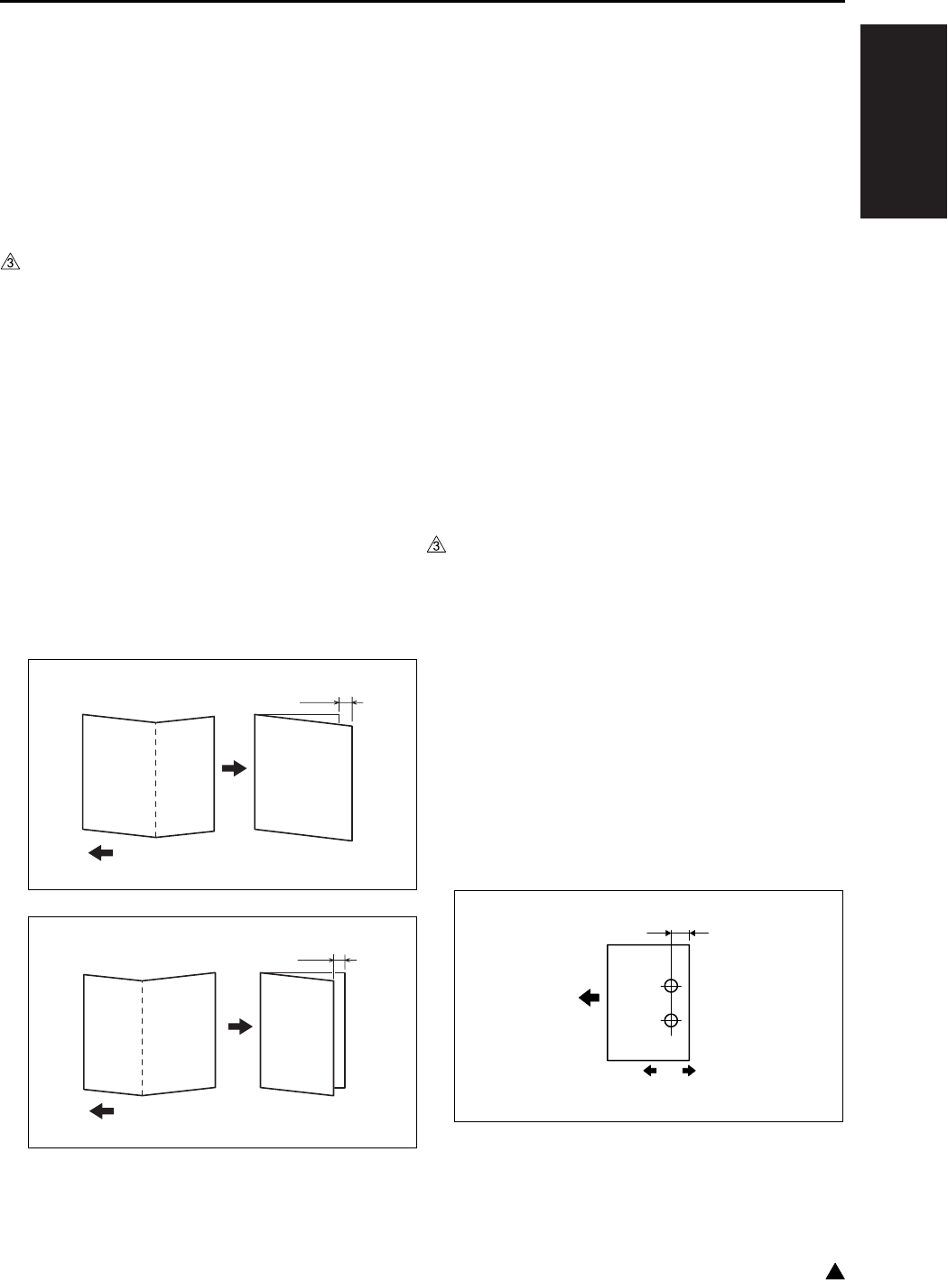
I ADJUSTMENT
36 MODE
1-73 3
8.17.2 Fold position adjustment (SK-114)
Adjust the fold position of the saddle kit.
It is adjusted when the fold unit is replaced, when
the fold position is incorrect, and when the folding
tilt adjustment is performed.
A. Procedure
1. Enter the 36 mode.
2. “36 mode menu screen”
Press any key to return again to “36 mode menu
screen”. Only through this operation, [10. FNS
adj.] is made effective.
Press the [10. FNS adj.] key.
3. On the “FNS adj. menu screen”,
select [2. Fold position adj.].
4. On the “Fold position adj. screen”, select the
paper size you want to adjust by using the arrow
keys.
5. Press the [Copy screen] key to output a fold
sample.
6. Fold the output sample along its crease.
7. Check the misalignment.
• Standard A, B: 0 ± 1.5mm
8. If it is not within the standard, press # button
while pressing ∗ button.
9. On the “Fold position adj. screen”,
enter a numeric value using the numeric key-
pad. Then, press [SET] key.
• Setting range: -10 ~ +10
1 step = 0.5mm
• In case of A: set a plus value
• In case of B: set a minus value
10. Repeat the steps 4 through 8 until the fold posi-
tion comes within the standard range.
11. Press [RETURN] and go back to the “FNS adj.
menu screen”.
8.17.3 Punch position adjustment (PK-114)
Adjust the hole positions of the punch kit.
A. Procedure
1. Enter the 36 mode.
2. “36 mode menu screen”
Press any key to return again to “36 mode menu
screen”. Only through this operation, [10. FNS
adj.] is made effective.
Press the [10. FNS adj.] key.
3. On the “FNS adj. menu screen”,
select [3. Punch position adj.].
4. Press the [Copy screen] key to output a
punched sample.
5. Check the hole positions on the sample.
• Standard A: 13 ± 3mm (2 holes)
9.5 ± 3mm (2 holes and 3 holes)
11 ± 3mm (4 holes)
4511D525AA
A
Exit direction
4511D526AA
B
Exit direction
A
[1] [2]
7145fs1040
Exit direction

I ADJUSTMENT
36 MODE
1-74
3
6. If it is not within the standard, press # button
while pressing ∗ button.
7. On the “Punch position adj. screen”,
enter a numeric value using the numeric key-
pad. Then, press [SET] key.
• Setting range: -10 ~ +10
1 step = 0.5mm
• To shift in [1] direction: set a plus value
• To shift in [2] direction: set a minus value
8. Repeat the steps 4 through 7 until the punch
positions come within the standard range.
9. Press [RETURN] and go back to the “FNS adj.
menu screen”.
8.17.4 Punch loop adjustment (PK-114)
Adjust the loop amount of the punch kit.
It is adjusted when the punch holes are tilted, or
when paper frequently jams in punch mode.
A. Procedure
1. Enter the 36 mode.
2. “36 mode menu screen”
Press any key to return again to “36 mode menu
screen”. Only through this operation, [10. FNS
adj.] is made effective.
Press the [10. FNS adj.] key.
3. On the “FNS adj. menu screen”,
select [4. Punch loop adj.].
4. On the “Punch loop adj. screen”, select the
paper size you want to adjust by using the arrow
keys.
5. Press the [Copy screen] key to output a
punched sample.
6. Check the tilt of holes on the sample.
7. If the holes are tilted, press # button while
pressing ∗ button.
8. On the “Punch loop adj. screen”,
enter a numeric value using the numeric key-
pad. Then, press [SET] key.
• Setting range: -4 ~ +4
1 step = 1.0mm
A
[1] [2]
7145fs1041
A
[1] [2]
7145fs1042
A
[1] [2]
7145fs1043
[2][1] 7145fs1044
[2][1] 7145fs1045

I ADJUSTMENT
36 MODE
1-75 3
• When the punch part JAM occurs frequently: set
a minus value
• When inclination is in a punch hole: set a plus
value (In both the cases of [1] and [2], it sets to
plus side.)
9. Repeat the steps 4 through 7 until there is no tilt.
10. Press [RETURN] and go back to the “FNS adj.
menu screen”.
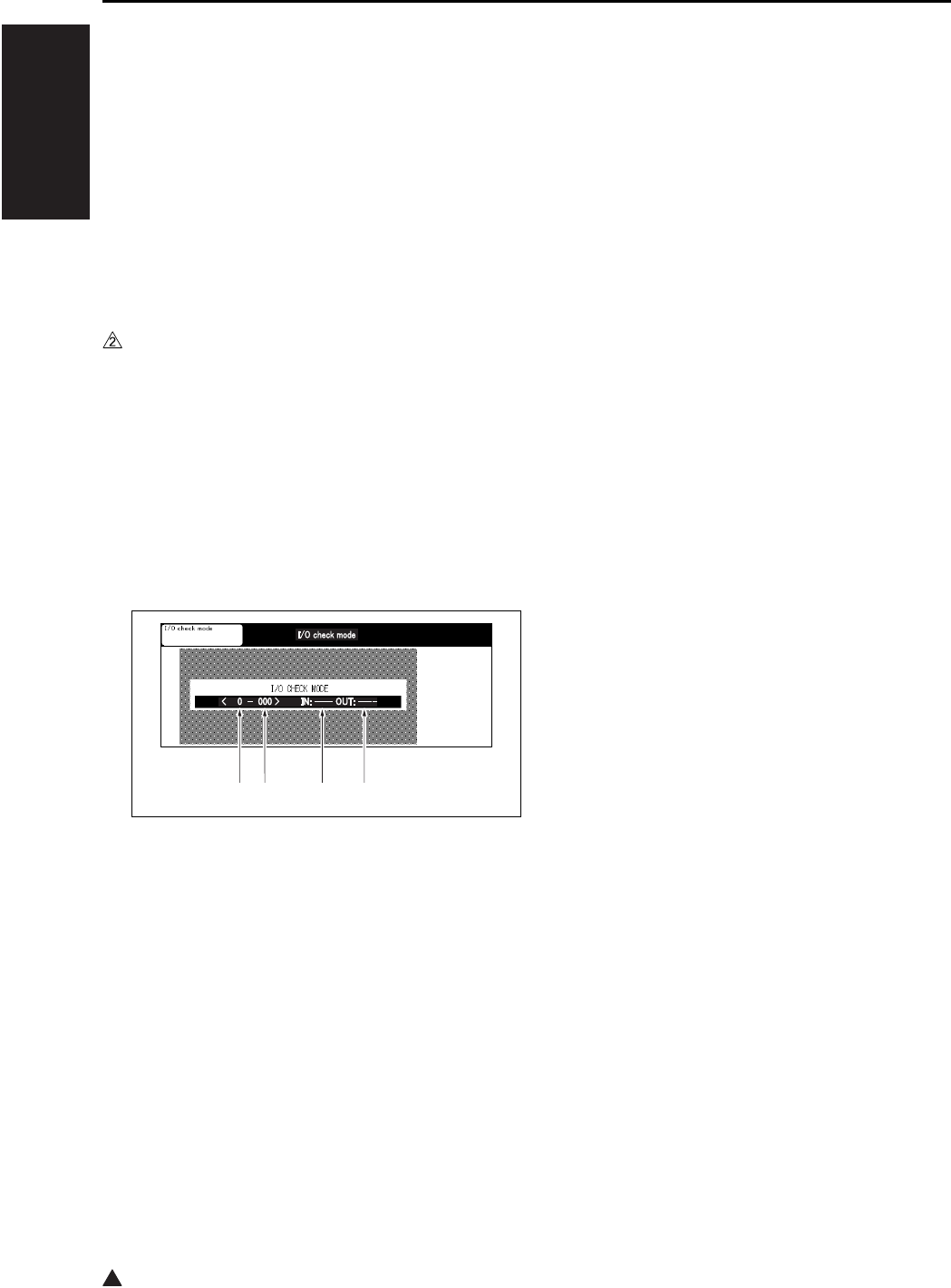
2
I ADJUSTMENT
47 MODE
1-76
9. 47 MODE
9.1 47 Mode Setting Method
A. 47 Mode
This mode provides self-diagnostic functions (input/
output check function) to check and adjustment the
various signals and loads.
B. Operation method (to start 47 mode)
(1) 47 Mode startup
a. Turn the SW2 (Sub power switch) OFF.
b. Turn the SW2 ON while pressing 4 and 7 of the
copy quantity setting buttons.
If security enhancement is enabled, input CE
password.
c. The moment “I/O check mode” is displayed in
the message display area at the center of the
screen, check to see if the 47 mode is acti-
vated.
“47 mode menu screen”
(2) Input check method
a. Using the numeric keys, enter the code input
for the desired signal (sensor, etc.) to check.
b. When using the multi mode, press the ∗ button
and enter the multi code according to the
desired input check item (signal) with the
numeric keys.
c. Procedure
1. Enter the 47 mode.
2. “47 mode menu screen”
Using the numeric keys, enter the input check
code. *1
3. When using the multi mode, press the ∗ button.
4. Using the numeric keys, enter the multi code.*1
5. Input check result will appear in the input check
result display area.
6. To check other signal input check, repeat steps
2 to 5.
*1 See “[5] Input check list”.
(3) Output check method
a. Enter the output code (see the input/output
check code) of the operating load you want to
check with the number of sheets setting button.
b. When using the multi mode, press the ∗ button
and enter the multi code according to the
desired output check item (load).
c. Press the [START] key to perform the output
check.
d. To end the output check, press the [STOP] key.
e. Procedure
1. Enter the 47 mode.
2. “47 mode menu screen”
Using the numeric keys, enter the output check
code.*2
3. When using the multi mode, press the ∗ button.
4. Using the numeric keys, enter the multi code.*2
5. Press the [START] key to perform the output
check.
6. To end the output check, press the [STOP] key.
7. To make another output check, repeat steps 2 to
6.
*2 See “[6] Output check list”.
(4) Exiting the 47 mode
To end the 47 mode, turn the SW2 OFF.
[1] Input/Output check code
[2] Multi code
[3] Input check
[4] Output check
[1] [2] [3] [4]

I ADJUSTMENT
47 MODE
1-77
1
9.2 RADF Original Size Detection
This adjustment is done when RADF fails to cor-
rectly detect size of an original.
A. Procedure
1. Enter the 47 mode.
2. “47 mode menu screen”
Press “69” by means of the numeric keys.
Check that “069-000” appears in the message
display area.
3. Set the original guide plate to the minimum size
(width) position, then press the [START] key.
4. To end the output check, press the [STOP] key.
5. Press the ∗ button.
6. Enter “1” from the the numeric keys.
Make sure that “069-001” is indicated in the
message display area.
7. Set the original guide plate to the maximum size
(width) position, then press the [START] key.
8. To end the output check, press the [STOP] key.
9. To end the 47 mode, turn the SW2 OFF.
9.3 Bypass Size Detection
Adjustment
Perform this adjustment if paper size detection at
the bypass feed tray does not function correctly.
A. Procedure
1. Enter the 47 mode.
2. “47 mode menu screen”
Press “28” by means of the numeric keys.
Check that “028-000” appears in the message
display area.
3. Set a sheet of A4R paper in the bypass tray.
4. Press the ∗ button.
5. Press [1] by means of the numeric keys.
Check that “028-001” appears in the message
display area.
6. Press the [START] key.
7. Press the [STOP] key.
8. Set a sheet of A4 paper in the bypass tray.
9. Press the ∗ button.
10. Press “2” by means of the numeric keys.
Check that “028-002” appears in the message
display area.
11. Press the [START] key.
12. To end the output check, press the [STOP] key.
13. Set a sheet of B6R paper in the Bypass tray.
14. Press the button.
15. Press [3] by means of the numeric keys.
Check that “028-003” appears in the message
display area.
16. Press the [START] key.
17. Press the [STOP] key.
18. To end the 47 mode, turn the SW2 OFF.
9.4 Action for Mounting When
Reinstalling the HDD
Removing the HDD for analysis of an abnormality
and then reinstalling it after turning on and off the
power may result in no recognition of the HDD. To
avoid a condition like this, conduct this setting.
A. Procedure
1. Enter the 47 mode.
2. “47 mode setting screen”
Press the No. of sheets setting button to enter
“15”. Check to see if “015-000” is displayed in
the message display column.
3. Press the ∗ button.
4. Press the No. of sheets setting button to enter
“97”.
Check to see if “015-097” is displayed in the
message display column.
5. Press the [START] key.
6. Press the [STOP] key to terminate the setting.
7. To end the 47 mode, turn the SW2 OFF.
Note:
• When the data is in nonconformity, an error may
occur. In that case, execute the format (key oper-
ator mode).
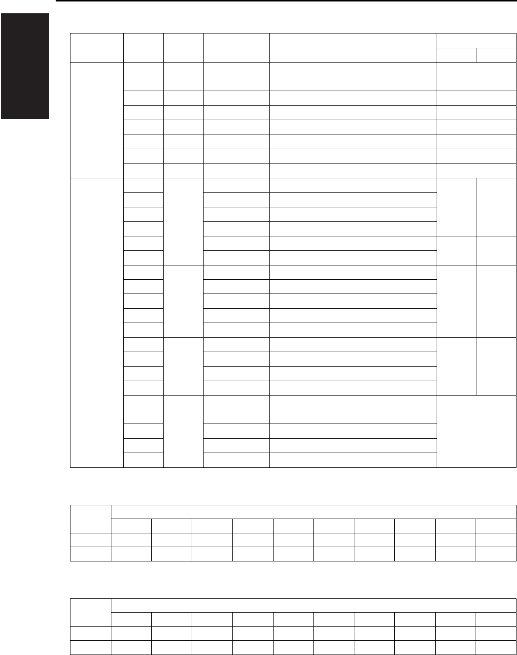
I ADJUSTMENT
47 MODE
1-78
9.5 Input Check List
*1 Paper size signal (Inch)
*1 Paper size signal (Metric)
Classification
Symbol Code Multi code Name Display
ON OFF
Analog
signal
TSCB 00 — Toner control sensor board
(Drum temperature)
0 to 255
TSCB 01 — Toner control sensor board 0 to 255
TSCB 02 — Toner control sensor board 0 to 255
TH1 03 — Fxing temperature sensor/1 0 to 255
TH2 04 — Fxing temperature sensor/2 0 to 255
TDS 05 — Toner temperature sensor 0 to 255
HUM1 06 — Humidity sensor 0 to 255
Paper feed PS8 10 1 No paper sensor/U Paper No paper
PS11 2 No paper sensor/L
PS103 3 No paper sensor/3
PS108 4 No paper sensor/4
PS13 5 Bypass tray no paper sensor No paper Paper
PS153 6 No paper sensor (LT-203)
PS7 12 1 Upper limit sensor/U Upper
limit
Not at
upper
limit
PS10 2 Upper limit sensor/L
PS102 3 Tray upper limit sensor/3
PS107 4 Tray upper limit sensor/4
PS152 6 Tray upper limit sensor (LT-203)
PS9 13 1 Tray set sensor/U Yes No
PS12 2 Tray set sensor/L
PS101 3 Tray sensor/3
PS106 4 Tray sensor/4
— 16 1 Main body upper tray paper size sig-
nal
0 to 9*1
— 2 Main body lower tray paper size signal
PSDTB/3 3 Paper size detection signal board/3
PSDTB/4 4 Paper size detection signal board/4
Tray Symbol displayed
1234567890
1 B5 B4 A5R A4 A4R F4 5.5 x 8.5 8.5 x 11
8.5 x 11R
8.5 x 14
2,3,4 A5R A4 A4R A3 F4 5.5 x 8.5 8.5 x 11 8.5 x 11R
8.5 x 14
11 x 17
Tray Symbol displayed
1234567890
1 B5 B4 A5R A4 A4R F4 5.5 x 8.5 8.5 x 11
8.5 x 11R
8.5 x 14
2,3,4 B5 B4 A5R A4 A4R A3 F4 8.5 x 11
8.5 x 11R
11 x 17

I ADJUSTMENT
47 MODE
1-79 3
*1 Paper size signal (Common)
*2 The results can be displayed by pressing the start button → the stop button in this order.
Tray Symbol displayed
1234567890
LCT(3) A4 A4R 8.5 x 11
8.5 x 11R
B5R B5 A4 A4R 8.5 x 11
8.5 x 11R
Classification
Symbol Code Multi code Name Display
ON OFF
Paper feed •
Conveyance
PS1 20 1 Registration sensor Paper No paper
PS104 2 Paper feed sensor/U (DB upper tray)
PS105 3 Paper feed sensor/L (DB lower tray)
PS21 4
(7145/7235/7228)
Timing sensor/U (Main body upper tray
)
PS22 5
(7145/7235/7228)
Timing sensor/L (Main body lower tray
)
PS155 6 Paper feed sensor (LT-203)
SW151 7 Interlock switch (LT-203) Open Close
PS2 22 1 Fixing exit sensor Paper No paper
SW3 23 1 Interlock switch Open Close
VR1 28 1 Bypass tray paper size sensor VR 0 to 255
Scanner — 38 1 Measured LD alarm value (LD1) 0 to 255
—2
(7145)
Measured LD alarm value (LD2) 0 to 255
——
(7235/7228/7222)
Measured LD alarm value 0 to 255*2
PS14 40 1
(7145)
Scanner home position sensor Other
than H.P.
H.P.
PS15 2 APS timing sensor Open Close
PS17 3 APS sensor
Original is
provided
No
original
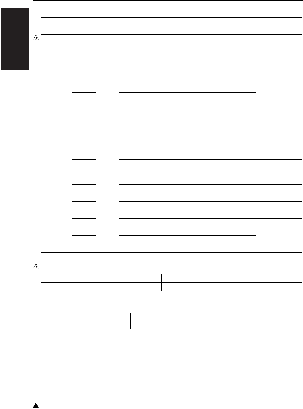
I ADJUSTMENT
47 MODE
1-80
3
*3 Judging code of the Main type (7235/7228/7222)
*4 Judging code of the DB type
Classification
Symbol Code Multi code Name Display
ON OFF
Intrinsic
functions
— 50 1 Check of DB serial communications
(7145)
Check of DF serial communications
(7235/7228/7222)
0001
Normal
0000
Abnormal
or not
connected
— 2 Check of FNS serial communications
— 3 Check of scanner serial communica-
tions
—4
(7235/7228/7222)
Check of Main drive board serial com-
munications
51 1 Judging of the main body type — (7145)
0096 to 0098*3
(7235/7228/7222)
— 2 Judging of the DB type 0 to 6*4
TLD 57 1 Toner level detector sensor Not
provided
Provided
PS5 2 Toner bottle sensor Provided Not
provided
RADF PS301 60 1 No original sensor Paper No paper
PS304 2 Cover open/close sensor Open Close
PS303 3 DF open/close sensor Open Close
PS308 4 Original registration sensor No paper Paper
PS309 5 Original conveyance sensor
PS302 6 Original exit sensor Paper No paper
PS305 7 Original size sensor/1
PS306 8 Original size sensor/2
VR301 9 Original size VR 0 to 255
Display 0096 0097 0098
Judging type 7222 7228 7235
Display 0 2 3 5 6
Judging type Not connected DB-211 DB-411 DB-211 + LT-203 DB-411 + LT-203
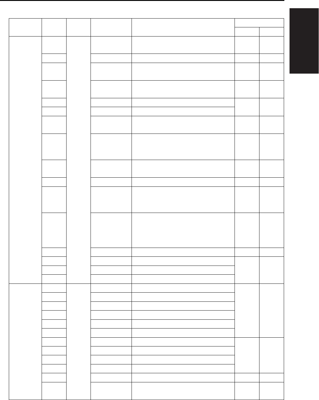
I ADJUSTMENT
47 MODE
1-81
Classification
Symbol Code Multi code Name Display
ON OFF
FS-112 PS701 70 1 Pressure sensor (Level) No
pressure
Pressure
applied
PS705 2 Shutter sensor ON OFF
PS701 3 Pressure sensor (HP) No
pressure
Pressure
applied
PS704 4 Paper exit full sensor Other
than full
Full
PS703 8 Exit sensor Paper No paper
PS702 9 FNS entrance censor
PS712 10 Stapler HP sensor Other
than H.P.
H.P.
PS713 12 Staple detection sensor No
staples
provided
Staples
provided
PS714 14 Stapler ready sensor Stapler
not ready
Stapler
ready
— 16 24V detect 0V 24V
PS711 17 Tray upper limit sensor Upper
limit
Not at
upper
limit
PS706 18 Tray lower limit sensor Lower
limit
Other
than
lower
limit
PS707 19 No paper sensor Paper No paper
PS708 20 Stapler unit HP sensor H.P. Other
than H.P.
PS709 21 Alignment HP sensor/R
PS710 22 Alignment HP sensor/F
FS-113 PC1 70 1 1st tray exit sensor Paper No paper
PC3 2 Stacking sensor
PC4 3 Upper path sensor
PC2 4 Lower path sensor
PC6 5 1st tray full detection sensor
PC7 6 Elevate tray full detection sensor
PC9 7 Alignment HP sensor H.P. Other
than H.P.
PC14 8 Staple home sensor
PC12 9 Stacking roller home sensor
PC13 10 Paper exit roller home sensor
PC5 11 Process tray paper detection sensor Paper No paper
— 12 Stapler 1 home sensor H.P. Other
than H.P.
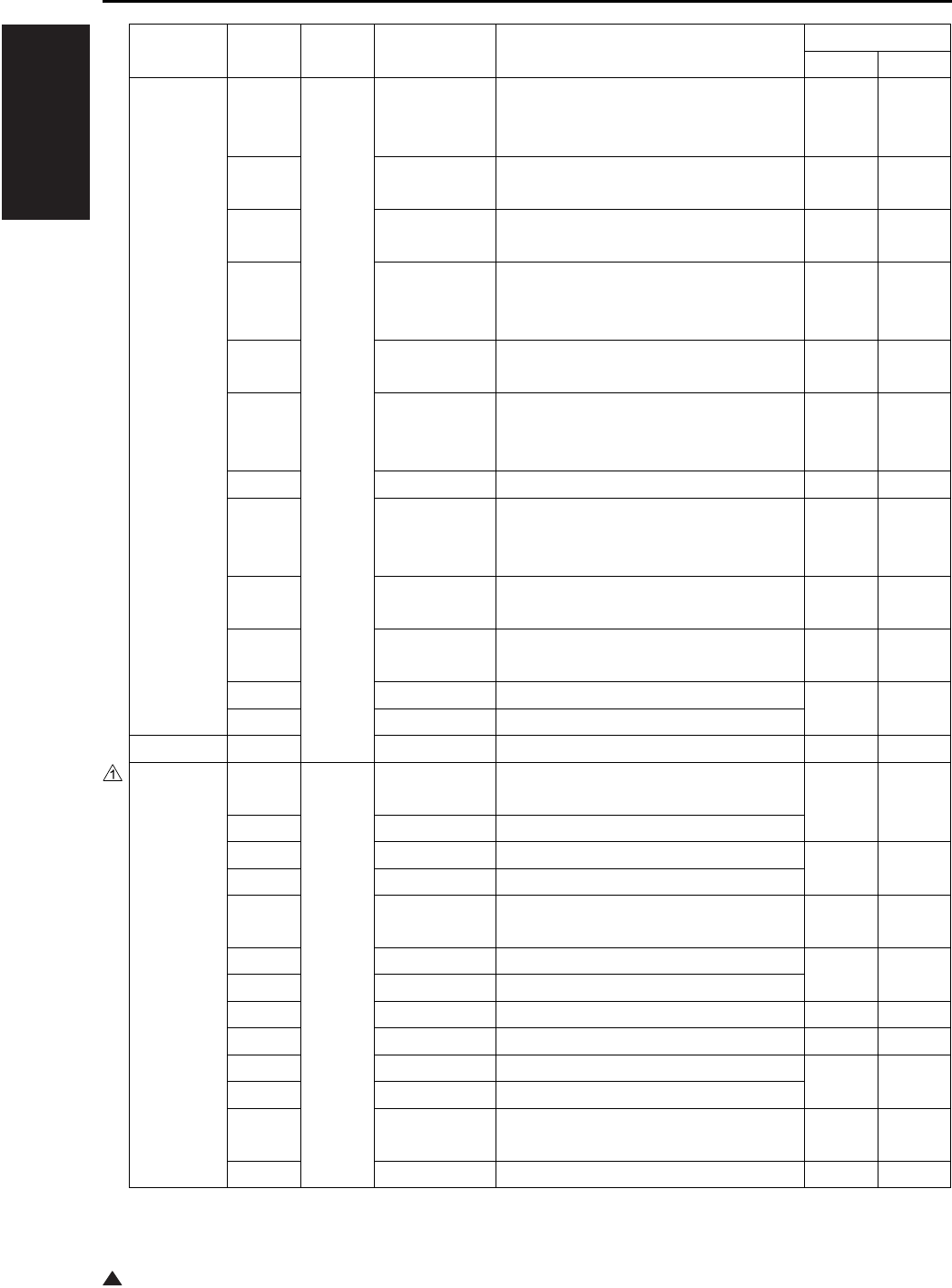
I ADJUSTMENT
47 MODE
1-82
1
FS-113 — 70 13 Staple empty detection sensor 1 No
staples
provided
Staples
provided
— 14 Self-priming sensor 1 Stapler
ready
Stapler
not ready
— 15 Stapler 2 home sensor H.P. Other
than H.P.
— 16 Staple empty sensor 2 No
staples
provided
Staples
provided
— 17 Self-priming sensor 2 Stapler
ready
Stapler
not ready
PWB-F 18 Elevate tray top face sensor Upper
limit
Not at
upper
limit
PC8 19 Elevate tray paper extractor sensor ON OFF
S2, S3 20 Elevate tray upper limit/lower limit
switch
Upper
limit
Not at
upper
limit
PC10 21 Shift home sensor H.P. Other
than H.P.
S4 22 Punch 2-hole/3-hole detection sensor
(inch system only)
2 holes 3 holes
PC15 23 Punch motor pulse sensor ON OFF
PC11 24 Shift motor pulse sensor
RU-101 PS2 27 Passage sensor Paper No paper
FS-114 PC4-FN 70 1 Entrance sensor Paper
exists
No paper
PC5-FN 2 Transport sensor
PC6-FN 3 Alignment home position sensor 1 Home
position
Except home
position
PC7-FN 4 Alignment home position sensor 2
S3-FN 5 Elevate tray upper/lower limit SW Upper
limit
Except
upper limit
S2-FN 6 Shutter detection SW Close Open
S1-FN 7 Front cover open/close detection SW
— 9 Pulse sensor Shade Transmit
PC23-SK 10 In & out guide home position sensor Shade Transmit
PC14-FN 11 Elevator tray lower limit sensor Shade Transmit
PC15-FN 12 Top face detection sensor
— 13 BK-114 detection
Equipped
Not
equipped
PC3-FN 14 Elevator tray position detect sensor Shade Transmit
Classification
Symbol Code Multi code Name Display
ON OFF

I ADJUSTMENT
47 MODE
1-83
FS-114 PC16-FN 70 15 Shutter home position sensor Home
position
Except home
position
PC11-FN 17 Exit paddle home position sensor
PC12-FN 18 Exit roller home position sensor
PC8-FN 19 Storage tray paper detect sensor
Paper exists
No paper
PC10-FN 20 Staple home position sensor Shade Transmit
— 21 Self-priming sensor
— 22 Staple empty detection sensor
— 23 Staple home sensor
— 25 Punch position sensor 1 Transmit Shade
— 26 Punch position sensor 2
PC1-PK 27 Punch trash full sensor Shade Transmit
PC22-SK 28 Crease roller home position sensor Home
position
Except home
position
S4-FN 29 Transport jam detection SW Close Open
PC26-SK 30 Layable guide home sensor Shade Transmit
PC20-SK 31 Saddle exit sensor
Paper exists
No paper
PC21-SK 32 Saddle tray empty sensor
— 33 Saddle staple home position sensor 1 Shade Transmit
— 34 Saddle self-priming sensor 1
—35
Saddle staple empty detection sensor 1
— 36 Saddle staple home position sensor 2
— 37 Saddle self priming sensor 2
—38
Saddle staple empty detection sensor 2
S4-SK 39 Saddle interlock switch Open Close
PC18-SK 40 Saddle exit roller home position sensor
Except home
position
Home
position
ADU PS4 80 — ADU sensor Open Close
Classification
Symbol Code Multi code Name Display
ON OFF

I ADJUSTMENT
47 MODE
1-84
3
9.6 Output Check List
Classification
Symbol Code Multi code Name
Cannot be set or
changed in the field
High volt-
age/image
L1 00 — Exposure lamp
M4 01 — Toner supply motor 1
M3 01
(7145)
— Developing motor
M1 01 — Main motor
SD9 01 — Toner solenoid
HV 02 — Charging X
03 — Transfer X
04 — Separation (AC) X
05 — Transfer + Separation (AC + DC) X
06 — Separation (DC) X
07 — Grid X
08 — Dmax/γ LED X
10
(7145)
— Guide plate X
11 — Bias (7145)
Bias + Guide plate (7235/7228/7222)
X
PRMB 15 1 Service counter clear (Clears service
related counter values from the PRMB
(Parameter memory board))
2
Reuse counter clear (prohibited in the field)
X
10 EKC data block clear
11 Job memory data block clear
12 Arbitrary replacement parts data block
clear
13
Coded dialing data block clear (for Fax)
14 One touch data block clear (for Fax)
15 Group data block clear (for Fax)
16 Fax file format (for Fax)
17 FL related non-volatile data initialization
(for Fax)
18 E-Mail address list clear
19 FTP address list clear
20 Box No. list clear
21 E-Mail Subject list clear
22 E-Mail Body list clear
23 Initialization of scanner file name
24 Initialization of copier file name
25 Initialization of SMB data
26 Initialization of LDAP data
90 Setting of system/copier and initialization
of memory switch
97 HDD mounting measure

I ADJUSTMENT
47 MODE
1-85 3
High volt-
age/image
PRMB 15 98 Initialize KRDS non volatile area
99 Initial generation of document folder
Paper feed SD1 20 1 1st paper feed solenoid/U
SD2 2 1st paper feed solenoid/L
SD3 3 Bypass solenoid
SD101 4 Paper feed solenoid/U
SD102 5 Paper feed solenoid/L
SD151 6 LT Paper feed solenoid
M9 21 1 Paper feed motor
M100 2 DB Paper feed motor
M150 3 LT Paper feed motor
M9, MC1,
MC2
4 Paper feed motor, registration clutch,
loop clutch
M7 23 1 Tray motor/U
M8 2 Tray motor/L
M101 3 Tray up motor/3
M102 4 Tray up motor/4
M151 5 Tray up motor
MC1 25 — Registration clutch
MC2 26 — Loop clutch
—28 1
Bypass size adjustment (A4R in width)
— 2 Bypass size adjustment (A4 in width)
—3
Bypass size adjustment (B6R in width)
SD7 29 — Separation claw solenoid
Scanner M2 31 1 Scanner motor
M5, FM7
(7235)
32 1 Polygon motor (steady rotation) *1
M5, FM7
(7235)
2 Polygon motor (Pre-rotation) *1
M2,L1 34 — Shading correction operation
LD 36 — Laser PWM (0 to 255)
LD,M5 37 — Conpel to laser ON
LD,M5 38 — LD alarm measurement
L1 39 — Platen still APS
Main body M11 40 — Fixing motor
M1 41 1 Main motor (sequential)
M1 2 Main motor (motor alone)
FM3 42 1 Internal dehumidifying fan/1
FM4 2 Internal cooling fan/1
*1 7235 only, FM7 (Polygon cooling fan) also rotates at the same time.
Classification
Symbol Code Multi code Name
Cannot be set or
changed in the field
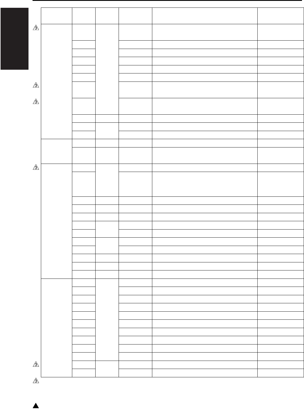
I ADJUSTMENT
47 MODE
1-86
3
Main body FM2 42 3
(7145/7235)
Fixing cooling fan
FM1 4 DC power supply cooling fan
FM5 5 Developing suction fan
FM6 6 Internal dehumidifying fan/2
FM3,FM6
7 Internal dehumidifying fan/1, 2
FM301 8 Cooling fan
FM7 9
(7145)
Internal cooling fan/2 (low speed)
FM7 10
(7145)
Internal cooling fan/2 (high speed)
TC 43 — Total counter
L2 45 1 Fixing heater lamp/1
L3 2 Fixing heater lamp/2
Operation
panel
OB 48 — All LED ON
OB 49 — Operation panel check (Checking for
LCD, keys, and buzzer)
Intrinsic
functions
M3 50 0 Developing motor (motor alone)
M3 (7145) 1 to 255 Developing motor (sequential)
• Use the multicode “1 to 255” to set the
No. of rotations.
PCL 51 — Pre-charging exposure lamp
TSL 52 — Transfer synchronization lamp
SD4 53 — Cleaning web solenoid
M4 55 1 Toner supply motor 1
M4, SD9 2 Toner supply motor 1, Toner solenoid
M10 56 1 Toner supply motor 2 (CW)
M10 2 Toner supply motor 2 (CCW)
TLD 57 — Toner level sensor
SD9 58 — Toner supply solenoid
— 59 — 24V power source remote
RADF M301 60 1 Original feed motor (CW)
M301 2 Original feed motor (CCW)
M303 3 Original reversal motor (CW)
M303 4 Original reversal motor (CCW)
M302 5
Original conveyance motor (CCW/50%)
M302 6
Original conveyance motor (CCW/100%)
M302 7
Original conveyance motor (CCW/400%)
SD302 8 Rollar pressure solenoid
SD301 9 Paper exit solenoid
SD303 10 Stamp solenoid
VR301 69* 0 Original size adjustment (small size)
VR301 1 Original size adjustment (large size)
* Be sure to execute the operation without fail when DF-320 is installed.
Classification
Symbol Code Multi code Name
Cannot be set or
changed in the field
I ADJUSTMENT
47 MODE
1-87 3
FS-112 M701 70 1 FNS conveyance motor
M702 2 Paper exit motor (forward rotation)
M702 3 Paper exit motor (reverse rotation)
M707 4 Pressure motor (forward rotation)
M707 5 Pressure motor (reverse rotation)
M706 6 Tray up motor(raise)
M706 7 Tray up motor (lower)
M705 8 Stapler shift motor, (initialize) (A4/F)
M705 9 Stapler shift motor, (initialize)(A4/R)
M703,M704
10 Alignment motor/R,F (initialize)
M703,M704
11 Alignment motor/R,F (A4 size position)
M703,M704
12 Alignment motor/R,F (rocking)
M708 13 Stapler motor
FS-114 M1-FN
M2-FN
M3-FN
70 1 Exit motor
Transport motor
Entrance motor
M4-FN
M5-FN
3 Alignment motor 1
Alignment motor 2
M11-FN 5 Elevator motor (up)
M11-FN 6 Elevator motor (down)
M12-FN 7 Shutter opening motor
M6-FN 11 Exit open/close motor
M9-SK 12 Saddle exit open/close motor
M7-FN 17 Stapling unit moving motor
M10-SK 23 Crease motor
SL1-FN 53 Storage paddle solenoid
SL2-FN 54 Exit paddle solenoid
— 78 Punch motor
— 79 Punch motor
IT SD8 75 1 IT gate solenoid
ADU M6 80 1 Forward rotation (7145: 230mm/sec,
7235: 180mm/sec, 7228/7222: 140mm/
sec)
M6 2 Forward rotation (600mm/sec)
M6 3 Reverse rotation (7145: 230mm/sec,
7235: 180mm/sec, 7228/7222: 140mm/
sec)
M6 4 Reverse rotation (600mm/sec)
SD5 83 — ADU gate solenoid
Classification
Symbol Code Multi code Name
Cannot be set or
changed in the field
I ADJUSTMENT
47 MODE
1-88
3
Others — 90 — PM counter clear
—91 0
Process counter clear (prohibited in the field)
X
—1
Drum counter clear (prohibited in the field)
X
— 92 — PRMB (Parameter memory board) initiali-
zation
(Process initial set/prohibited in the field)
X
— 93 — Initial settings
— 95 — Automatic adjustment of L detection ref-
erence value
(prohibited in the field)
X
— 96 — Process delivery completing setting (pro-
hibited in the field)
X
— 97 — Light distribution check
— 98 — After completion of process shipment,
temporary initialization of the PRMB
(Parameter memory board)
X
— 119 — Network initialization
— 121 —
Initialize fax-related nonvolatile memory
— 197 — E-RDH (DRAM) capacity display
— 198 — E-RDH (DRAM) capacity check
— 999 — Checking of status control board (prohib-
ited in the field)
X
Classification
Symbol Code Multi code Name
Cannot be set or
changed in the field
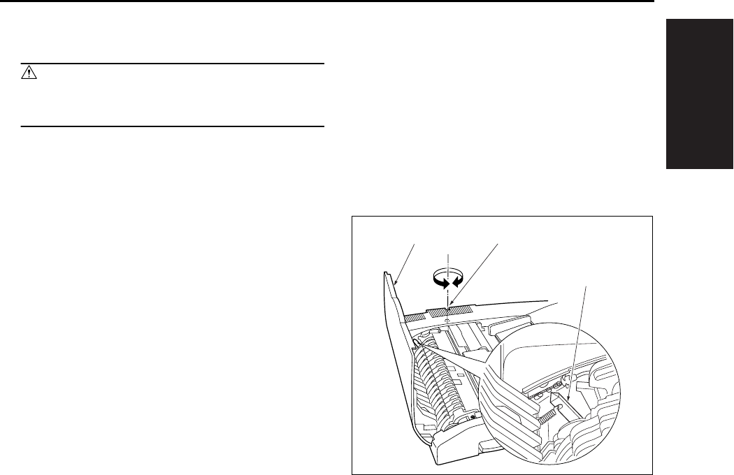
I ADJUSTMENT
OTHER ADJUSTMENTS
1-89
10. OTHER ADJUSTMENTS
Caution:
• Be sure the power cord has been unplugged
from the wall outlet.
10.1 RADF Height Adjustment
A. Procedure
1. Close the RADF.
2. Open the open/close cover [1], then turn the
RADF height adjustment screw [2] until the
RADF height adjust pointer [3] comes to center
of the scale divisions.
[1] [2]
[3]
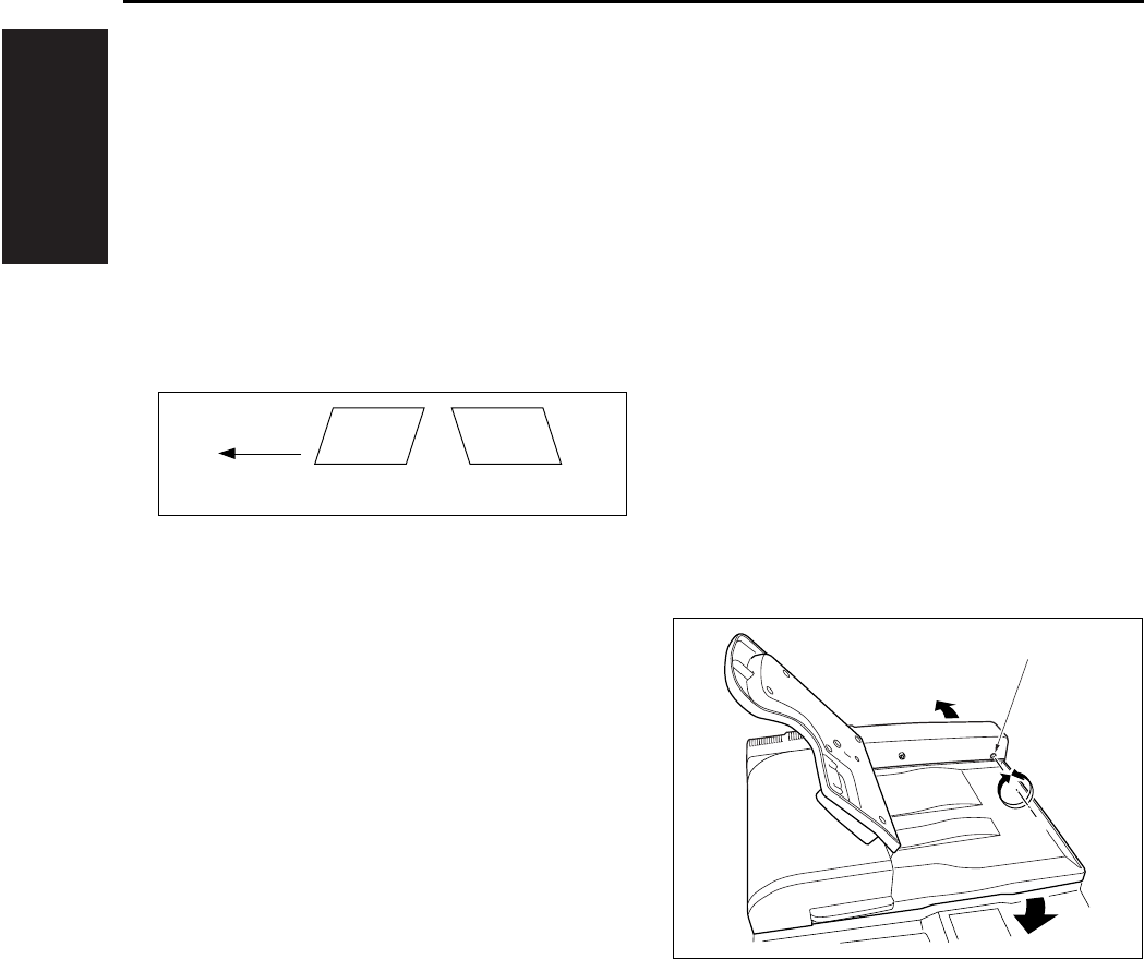
I ADJUSTMENT
OTHER ADJUSTMENTS
1-90
10.2 RADF Distortion Adjustment
Adjust the amount of distortion of a copy in the fol-
lowing procedures.
A. Procedure
1. Set a A3 paper on the tray of the main body.
2. Set the ADF adjustment chart on the RADF,
then make a copy.
3. Check the amount of distortion in the copy.
Standard value: ± 0.3% less.
4. When the distortion is larger than the tolerance,
adjust it using the skew adjustment screw [1].
• A: Turn the dskew adjustment screw [1] clock-
wise.
• B: Turn the skew adjustment screw [1] counter-
clockwise.
5. Repeat above steps 2 to 4 until the standard
value for distortion is met.
[1] Paper feed direction
A B
[1]
[1]
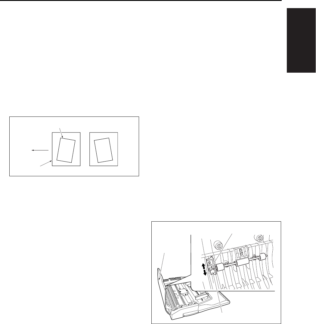
I ADJUSTMENT
OTHER ADJUSTMENTS
1-91
10.3 RADF Original Skew Adjust-
ment (Front Side)
When the front side of the originals are fed being
skewed, adjust the registration pully bracket.
A. Procedure
1. In the single sided → single sided copy mode,
set the adjustment chart to the RADF for copy-
ing.
2. Check the original skew pattern.
Standard value: Within ± 0.5%
3. When the skew is not up to the standard, open
the open/close cover [1], loosen the screw [3]
and adjust the position of the registration pulley
bracket[2].
• A: Move the registration pully bracket [2] down
[4].
• B: Move the registration pully bracket [2] up [5].
4. Repeat above steps 1 to 3 until the standard
value for the skewed original is within standard
value.
[1] Image
[2] Paper
[3] Paper feed direction
[1]
[2]
[3]
AB
[1]
[2]
[5]
[4]
[3]

I ADJUSTMENT
OTHER ADJUSTMENTS
1-92
10.4 RADF Original Skew Adjust-
ment (Back Side)
When the back side of the original is supplied on a
skew, adjust the clearance of the guide plate.
A. Procedure
1. In the double sided → single sided copy mode,
set the adjustment chart to the RADF for copy-
ing.
2. Check the original skew pattern.
Standard value: Within ± 0.5%
[1] Image
[2] Paper
[3] Paper feed direction
[1]
[2]
[3]
AB
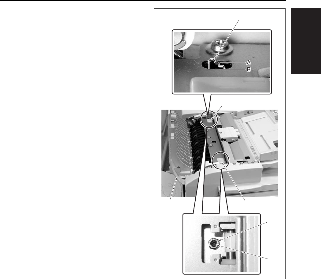
I ADJUSTMENT
OTHER ADJUSTMENTS
1-93
3. When the skew is not up to the standards, open
the open/close cover [1] and remove the 2 cov-
ers [2].
4. Loosen the hexagon nut [3], and rotate the set
screw[4] to adjust the clearance of the guide
plate.
• A: Loosen the hexagon nut [3] at the rear and
rotate the set screw [4] clockwise.
• B: Loosen the hexagon nut [3] at the front and
rotate the set screw [4] clockwise.
Note:
• Since there is the possibility of jamming, be sure
not make the clearance of the guide plate nar-
rower than the standard value. (Be sure not to
tighten the hexagon nut [3].)
• The reference value of the clearance of the guide
plate should be determined based on the position
where the difference in level [A] of the second
stage of the clearance reference block [5]
becomes flush with the metal frame surface [B].
5. Repeat the steps 1 to 4 until the original skew
gets within the standard value.
[1] [2]
[2]
[3]
[4]
[5]
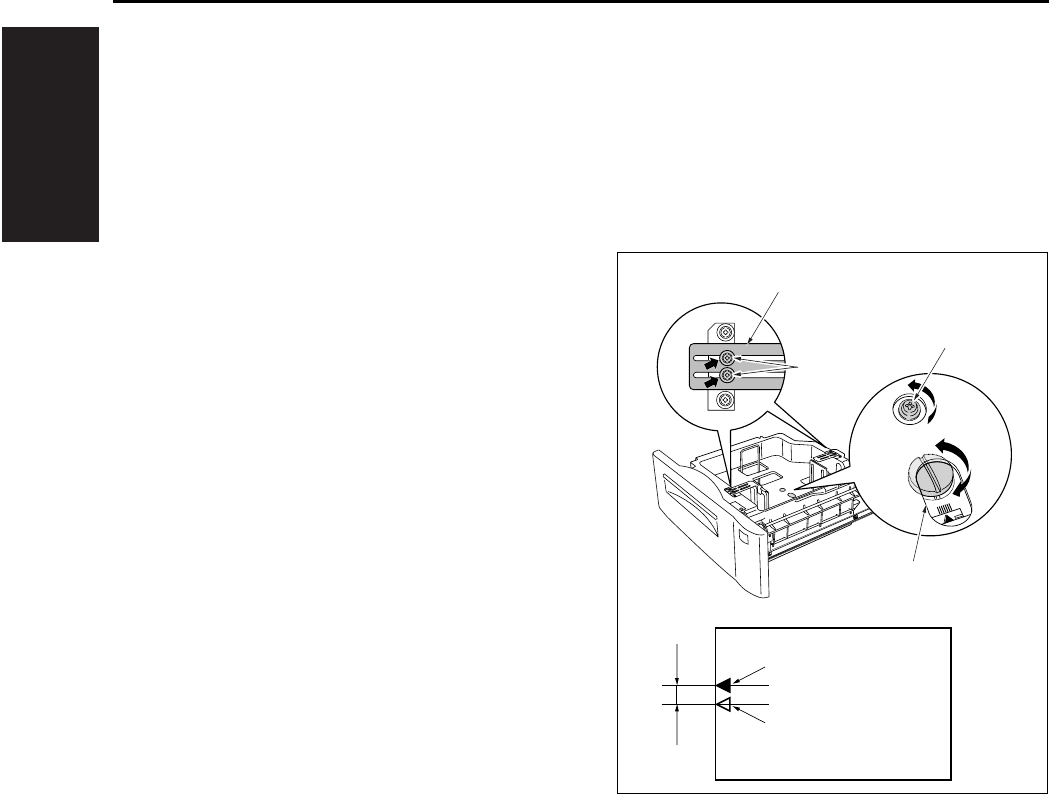
I ADJUSTMENT
OTHER ADJUSTMENTS
1-94
10.5 DB-411 Paper-Centering
Adjustment
Make a copy of the test chart, then perform neces-
sary adjustment until the standard value for the
paper centering is fit.
A. Procedure
1. Loosen a screw [1] on the side guide situated at
bottom of the paper feed tray. And also loosen
the 2 screws [3] on the reinforcing plates (front/
back) [2] situated at top of the tray.
2. Rotate the adjusting cam [4], move the side
guide back and forth and adjust it so that the
centering of the image center [6] to the paper
center [5] becomes within the specified value
(within 3mm).
3. When the adjustment is complete, tighten the
screws provided for the side guide and reinforc-
ing plates.
Note:
• If paper miscentering occurs, move the side guide
forwards and backwards, and adjust the gap for
the paper in use to between 1.0 and 1.5mm.
(The gap must be set so that the tray meets both
the lower limit position and the upper limit posi-
tion.)
[2]
[3]
[1]
[4]
[7]
[6]
[5]
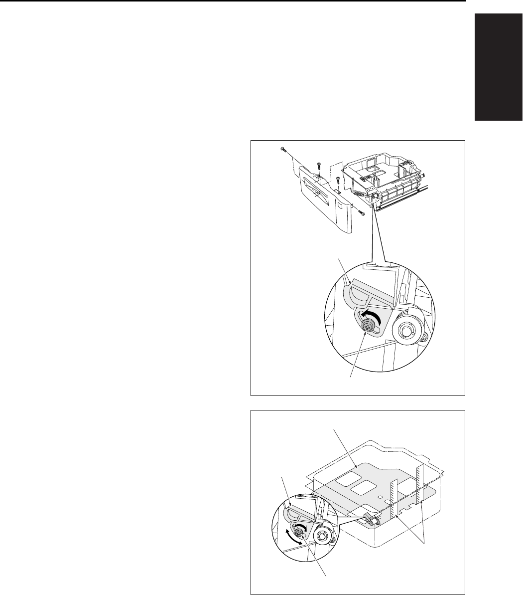
I ADJUSTMENT
OTHER ADJUSTMENTS
1-95
10.6 DB-411 Tray Tilt Adjustment
Normal paper feed can't be expected if the tray is
tilted. In such case, adjust the tray and paper feed
roller shaft so that they may be parallel in each
other. Whenever the wire is replaced, this adjust-
ment must be implemented.
A. Procedure
1. Remove the front cover of the tray.
2. Loosen a screw [2] of the wire adjustment part
[1] situated in front side of the tray.
3. Position in front and in rear the 2 metal scales
[2] in the tray [1] as shown in the drawing.
4. Move the wire adjustment part [3] until the dis-
tance from top of the side plate to the tray [1] top
face is equal in both the front and back sides.
5. When the adjustment is complete, tighten the
screw [4] for the wire adjustment part [3].
[1]
[2]
[1]
[2]
[3]
[4]
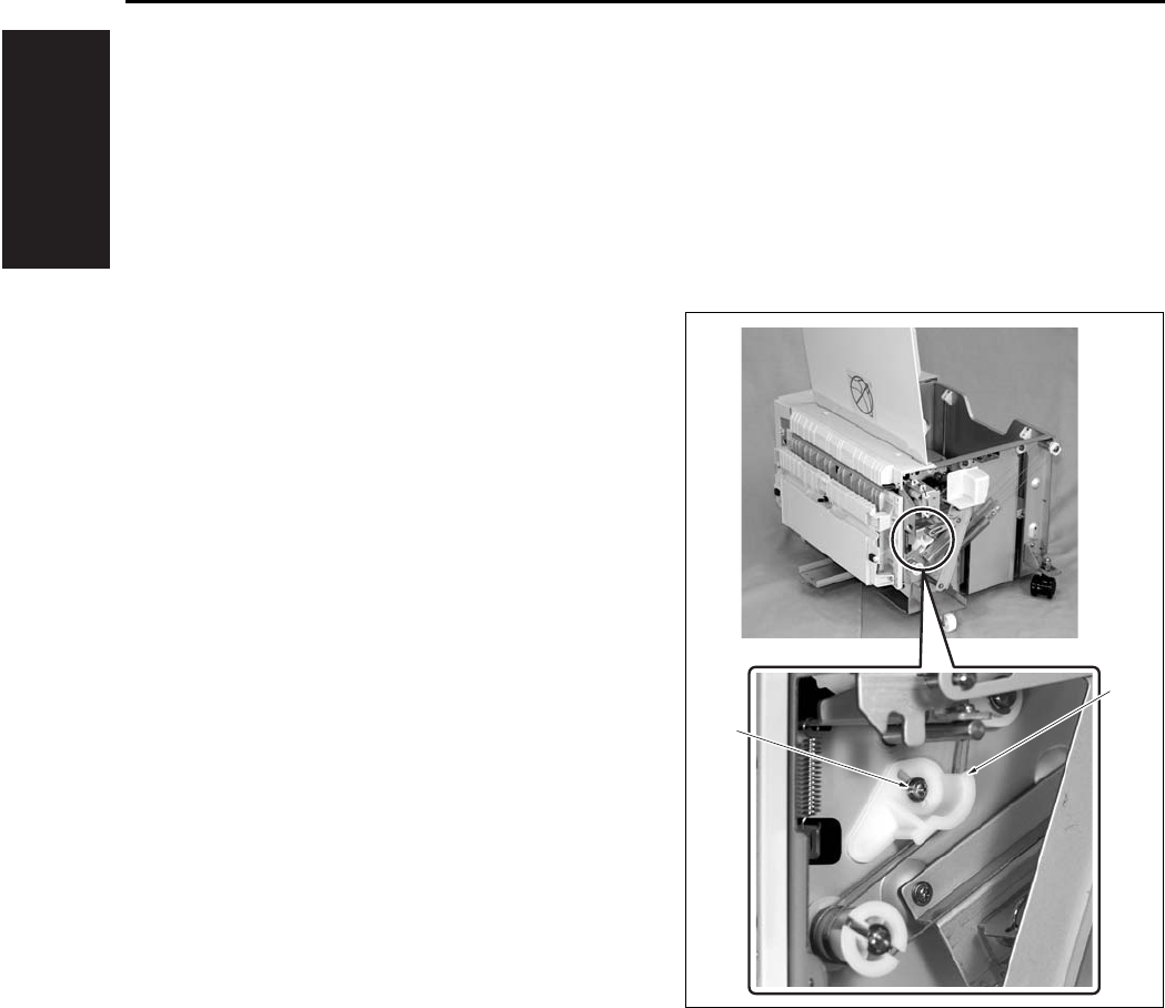
I ADJUSTMENT
OTHER ADJUSTMENTS
1-96
10.7 LT Tray Tilt Adjustment
Normal paper feed can't be expected if the tray is
tilted. In such case, adjust the tray and paper feed
roller shaft so that they may be parallel in each
other. Whenever the wire is replaced, this adjust-
ment must be implemented.
A. Procedure
1. Remove the LT from the main body.
2. Open the top cover and remove the right cover
and the front cover.
3. Loosen a screw [2] of the wire adjustment part
[1] situated in front.
[1]
[2]
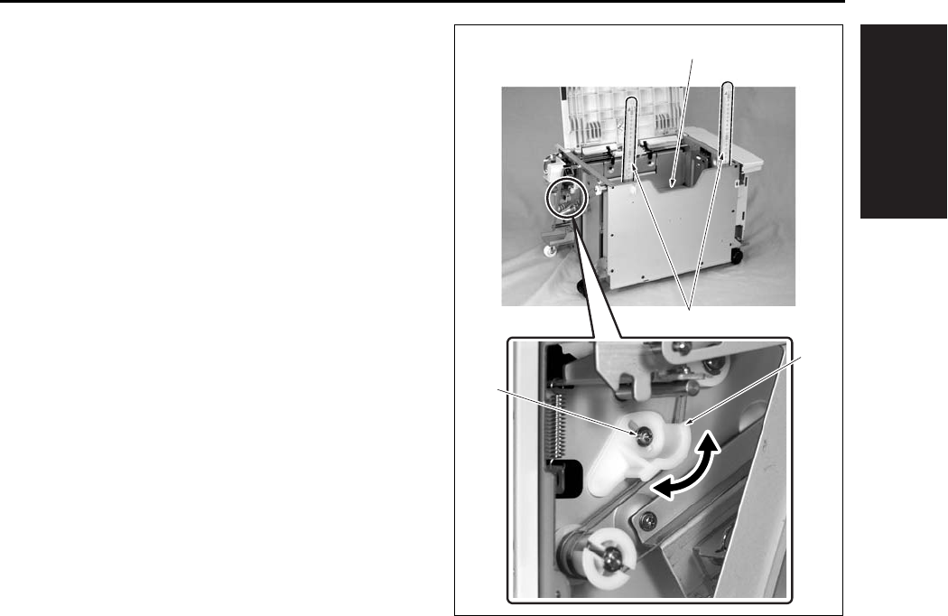
I ADJUSTMENT
OTHER ADJUSTMENTS
1-97
4. Position in front and in rear the 2 metal scales
[2] in the tray [1] as shown in the drawing.
5. Move the wire adjustment part [3] until the dis-
tance from top of the side plate to the tray [1] top
face is equal in both the front and back sides.
6. When the adjustment is complete, tighten the
screw [4] for the wire adjustment part [3].
[3]
[2]
[1]
[4]
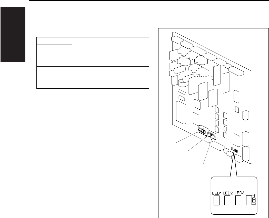
I ADJUSTMENT
OTHER ADJUSTMENTS
1-98
10.8 FS-113 Output Check Mode
A. Switches on PWB
S1 Used to run the Test Mode opera-
tion.S2
S3 DIP switch used to set the Test
Mode operation.
LED1~4 Turn ON or OFF, or blink to indi-
cate a specific condition during
Test Mode operations.
S1
S2
S3

I ADJUSTMENT
OTHER ADJUSTMENTS
1-99
B. Test Mode
(1) Test Mode Setting Procedure
a. Procedure
1. Turn OFF SW2 (Sub power switch) of the
copier.
2. Flip keys of the DIP switch into the ON or OFF
position as necessary. (See Table below.)
3. Turn ON SW2 (Sub power switch) of the copier.
4. This sets the Finisher into the corresponding
Test Mode operation.
b. Resetting Procedure
• Flip all keys of the DIP switch to their respective
initial positions (OFF positions) and turn OFF,
then ON, SW2 (Sub power switch) of the copier.
(2) Test Mode Operations
Test Mode
Operation
DIP Switch (S3) LED
12341234
Online {{{z
1st Tray exit ON z{{{
Elevator Tray
exit ON {z{{
Finisher Tray
exit ON ON zz{{
Shifting
operation ON ON z{z{
Aligning Plate
operation ON ON {z z{
Stapling Unit
CD movement ON ON ON zzz{
Exit Roller/
Rolls spacing ON {{{z
Storage Roller/
Rolls spacing ON ON z{{z
Elevator Tray
operation ON ON {z{z
Hole Punch
operation ON ON ON zz{z
Hole position
selection ON ON {{ z z
Sensor test ON ON ON Indicates sen-
sor state
z: Blinking {: OFF

I ADJUSTMENT
OTHER ADJUSTMENTS
1-100
(3) Operation in Each Test Mode Operation
a. 1st Tray Exit
b. Elevator Tray Exit
c. Finisher Tray Exit
d. Shifting Operation
Motors and solenoids: Energized
[Entrance Motor (M1), Upper Entrance Motor
(M4), Upper/Lower Entrance Switching Sole-
noid (SL1), 1st Tray Entrance Selecting Sole-
noid (SL2)]
Motors and solenoids: Deenergized
[Entrance Motor (M1), Upper Entrance Motor
(M4), Upper/Lower Entrance Switching Sole-
noid (SL1), 1st Tray Entrance Selecting Sole-
noid (SL2)]
S1: ON
S2: ON
S1: ON
S2: OFF
Motors: Energized
[Entrance Motor (M1), Upper Entrance Motor
(M4), Lower Entrance Motor (M2), Exit Motor
(M3)]
Motors: Deenergized
[Entrance Motor (M1), Upper Entrance Motor
(M4), Lower Entrance Motor (M2), Exit Motor
(M3)]
S1: ON
S2: OFF
Motors and solenoids: Energized
[Entrance Motor (M1), Upper Entrance Motor
(M4), Lower Entrance Motor (M2), Exit Motor
(M3), Upper/Lower Entrance Switching Sole-
noid (SL1)]
Motors and solenoids: Deenergized
[Entrance Motor (M1), Upper Entrance Motor
(M4), Lower Entrance Motor (M2), Exit Motor
(M3), Upper/Lower Entrance Switching Sole-
noid (SL1)]
S1: ON
S2: ON
The Elevator Tray shifts to the front.
The Elevator Tray shifts to the rear.

I ADJUSTMENT
OTHER ADJUSTMENTS
1-101
e. Aligning Plate Operation
f. Stapling Unit CD Movement
g. Exit Roller/Rolls Spacing
h. Storage Roller/Rolls Spacing
S1: ON
S1: ON
At the home position
At a position to align A4 paper
S1: ON
At a position to align 8.5 x 11R paper
S1: ON
At a position to align 8.5 x 11 paper
S1: ON
At a position to align A4R paper
S1: ON
S1: ON
At home position
At a position for A4 corner stapling
S1: ON
At a position for A4R corner stapling
S1: ON
At home position
S1: ON
S2: ON
Pressed
Separated
S1: ON
S2: ON
Pressed
Separated
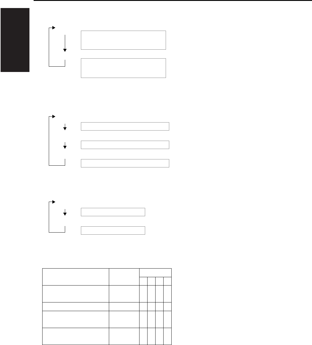
I ADJUSTMENT
OTHER ADJUSTMENTS
1-102
i. Elevator Tray Operation
j. Hole Punch Operation
k. Hole Position Selection U.S.A. and Canada
l. Sensor Test
Sensor State LED
1234
Elevator Tray Upper Limit
Sensor PQ (PWB-D)
Unblocked {{{z
Storage Sensor (PC3) Blocked {{z{
Lower Entrance Sensor
(PC2) Blocked {z{{
Upper Entrance Sensor
(PC4) Blocked z{{{
z: ON {: OFF
S1: ON
S2: ON
Goes up until the Elevator Tray Upper Limit
Sensor PQ
(PWB-D) is blocked.
Goes down until the Elevator Tray Upper Limit
Sensor PQ
(PWB-D) is unblocked.
S1: ON
S1: ON
The Punch Motor (M11) is energized.
The electromagnetic spring clutch is energized.
S2: ON
The Punch Motor (M11) is deenergized.
S1: ON
S2: ON
2-hole position
3-hole position
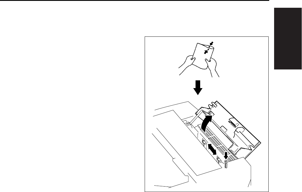
I ADJUSTMENT
OTHER ADJUSTMENTS
1-103
10.9 Lengthwise Position Adjustment
of Punch Hole of FS-113
A. Procedure
1. Set the copier into the Hole Punch mode and
make a 1-sided copy from a 1-sided original.
2. Fold the copy in half and check to see if the
holes are aligned
(deviation should be within 2mm).
3. If the holes are misaligned, loosen the screw
that secure the Punch Unit and slide the Punch
Unit as necessary.
4. Make a copy again and check for correct hole
positions.
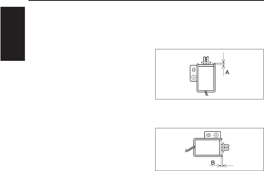
I ADJUSTMENT
OTHER ADJUSTMENTS
1-104
10.10 Adjustment of FS-113 Sole-
noids
A. Adjustment of the Upper/Lower Entrance
Switching Solenoid (SL1)
(1) Procedure
1. Loosen one screw that secures the solenoid in
position.
2. Move the solenoid up or down and, when
dimension A measures 4.4mm, tighten the
screw.
B. Adjustment of the 1st Tray Entrance Select-
ing Solenoid (SL2)
(1) Procedure
1. Loosen one screw that secures the solenoid in
position.
2. Move the solenoid to the right or left and, when
dimension B measures 3.6mm, tighten the
screw.
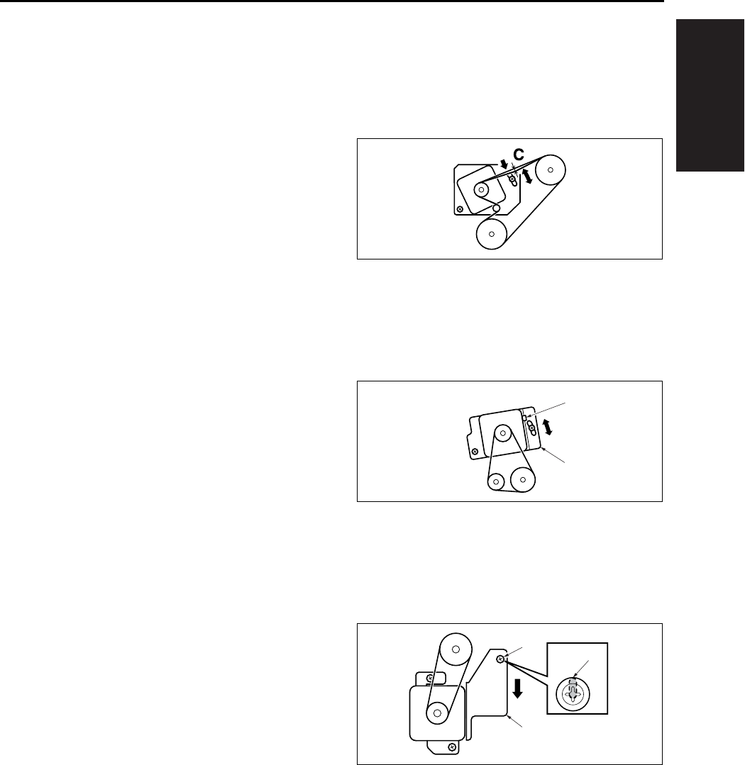
I ADJUSTMENT
OTHER ADJUSTMENTS
1-105
10.11 FS-113 Timing Belt Tension
Adjustment
A. Adjustment of the Upper Entrance Motor
(M4) Timing Belt
(1) Procedure
1. Loosen 2 screws.
2. Use a spring balance to apply pressure at C and
tighten the 2 screws at the position where the
tension becomes 200 ± 100gf when the belt
deflects 4mm.
B. Adjustment of the Lower Entrance Motor
(M2) Timing Belt
(1) Procedure
1. Loosen 2 screws.
2. Use a spring balance to pull the square hole [2]
given in the lower entrance motor mounting
bracket with a force of 800 ± 50gf and tighten
the 2 screws.
C. Adjustment of the Exit Motor (M3) Timing
Belt
(1) Procedure
1. Loosen 3 screws.
2. Tighten the 3 screws at the position [3] where
the external form of the screw [1] coincides with
that of the oblong hole in the exit motor mount-
ing bracket [3].
[1]
[2]
[1]
[2]
[3]
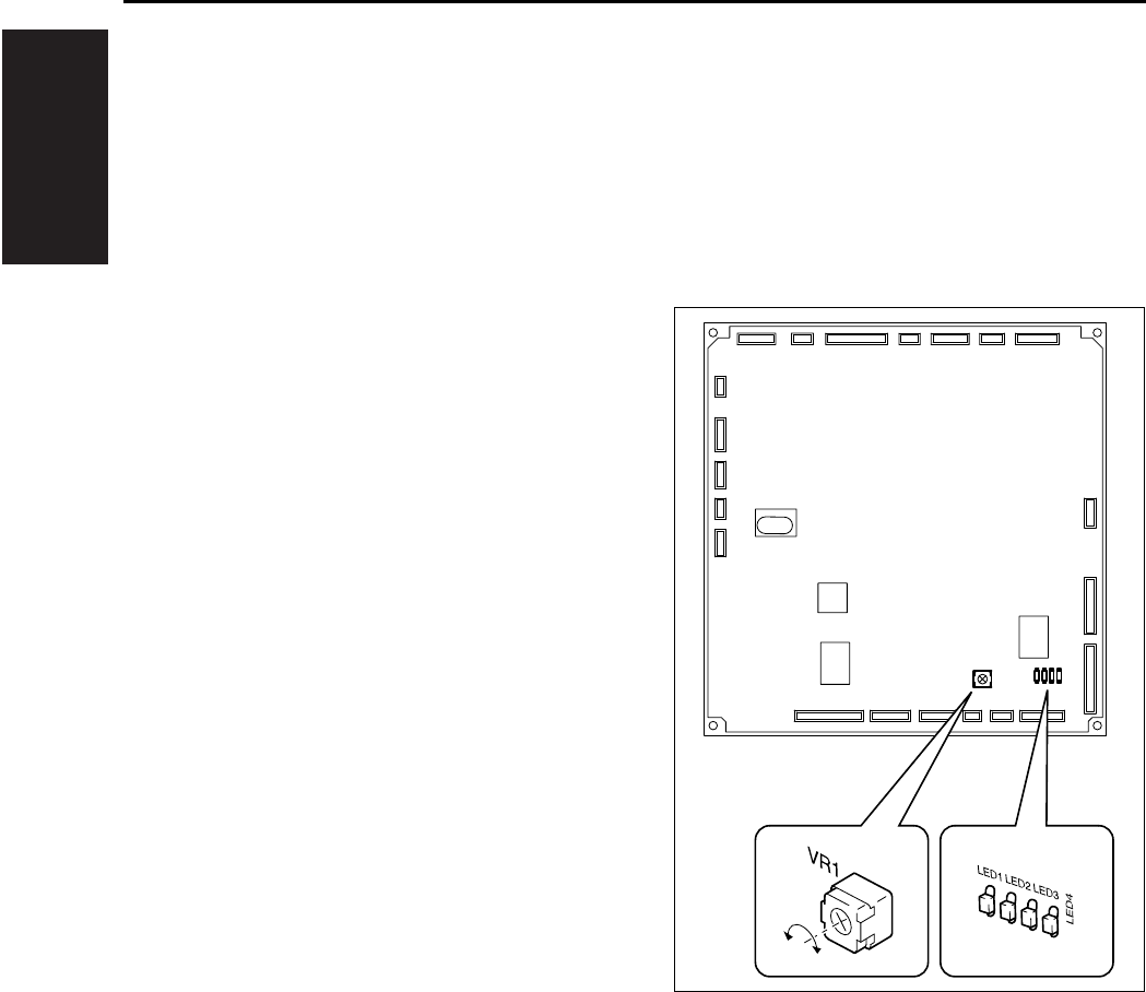
I ADJUSTMENT
OTHER ADJUSTMENTS
1-106
10.12 FS-113 Adjustment of the
Elevator Tray Upper Limit
Sensor
• This adjustment must be made when the Control
Board (PWB-A) or the Elevate Tray Top Face
Sensor (PWB-C, D) is replaced with a new one.
A. Procedure
1. Set up the sensor test mode.
2. Turn VR1 on PWB-A fully counterclockwise.
3. Using a sheet of paper, block the Elevator Tray
Upper Limit Sensor LED (PWB-C).
4. Check that LED4 on PWB-A turns OFF. If it
stays ON, slowly turn VR1 clockwise and stop
turning it as soon as the LED turns OFF.
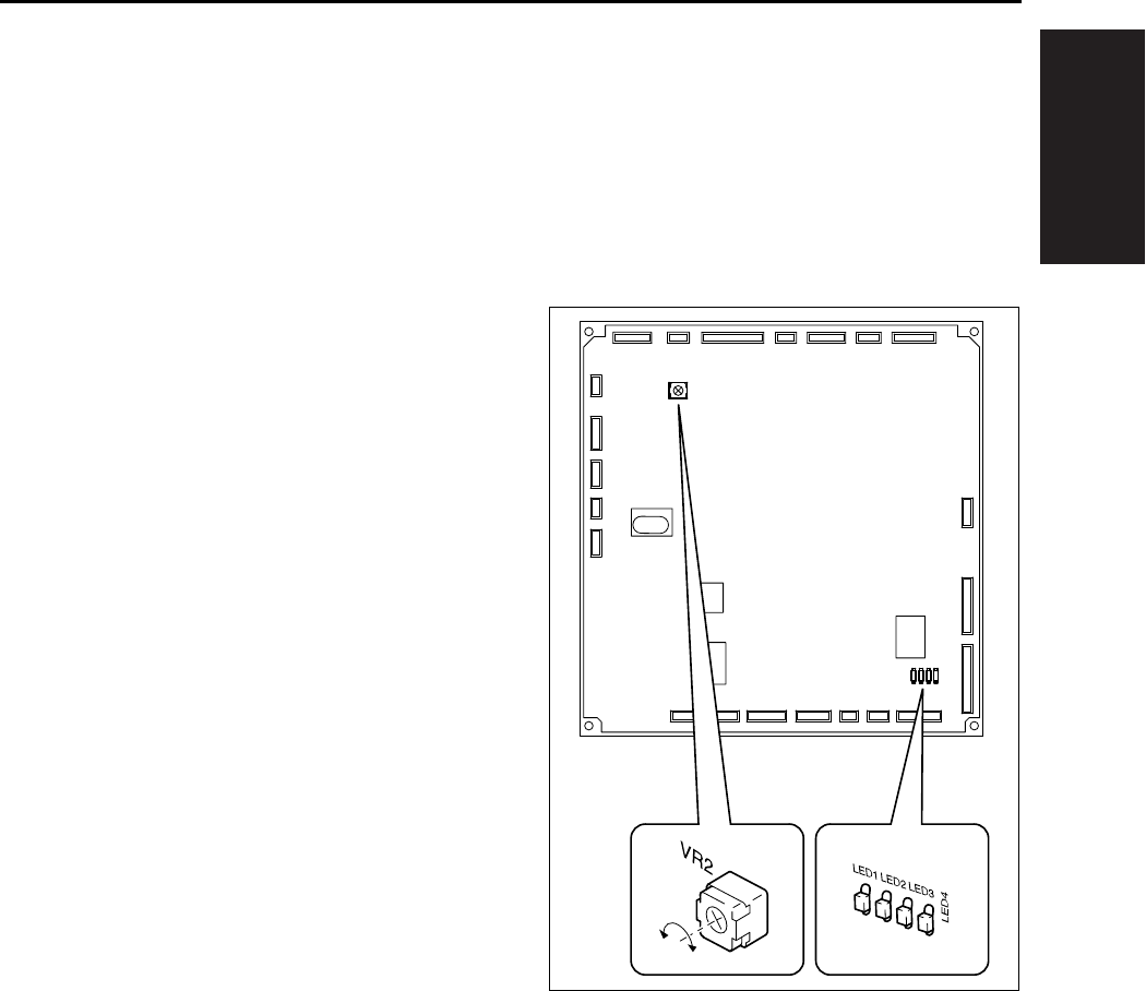
I ADJUSTMENT
OTHER ADJUSTMENTS
1-107
10.13 Adjustment of FS-113 Eleva-
tor Tray Overload Detection
Level
• This adjustment must be made when the Control
Board (PWB-A) or the Elevator Motor (M7) is
replaced with a new one.
A. Procedure
1. Set the “Elevator Tray operation” function of the
Test Mode.
2. Turn VR2 on PWB-A fully counterclockwise.
3. Using a sheet of paper, block the Elevator Tray
Upper Limit Sensor LED (PWB-C). Then using
the “Elevator Tray operation” function, lower the
Elevator Tray.
4. Place 1,500 sheets of A3 (20lbs) or 3,000
sheets of A4 (20lbs) paper on the Elevator Tray.
5. Using the “Elevator Tray operation” function,
raise the Elevator Tray.
6. While the Elevator Tray is going up, turn VR2 on
PWB-A clockwise and, when LED3 on PWB-A
turns from a steady light to off, stop turning VR2.

I ADJUSTMENT
OTHER ADJUSTMENTS
1-108
1
10.14 Staple Position Adjustment
of FS-114
• It is replaced when the stapler is replaced or
when the staple position is not correct.
A. Procedure
1. Set the staple mode and make a copy.
2. Check the staple position of the paper.
• 1-Point Tilted Staple
Paper Width 279 to 297mm: 45° tilt
B5, B4: 30° tilt
• 1-Point Parallel Staple
Paper Width 182 to 216mm
Measurement
position
Specification Adjustment range
A, D 4.4 ± 3mm —
B, C 12.1 ± 4mm +1mm to -2mm
Measurement
position
Specification Adjustment range
A 4.9 ± 3mm —
B 16.2 ± 4mm +1mm to -2mm
C 10.1 ± 4mm +1mm to -2mm
D 6.5 ± 3mm —
Measurement
position
Specification Adjustment range
A 4.5 ± 3mm —
B 6.0 ± 4mm +1mm to -2mm
A
B
C
D
4349D503AA
A
B
4349D504AA
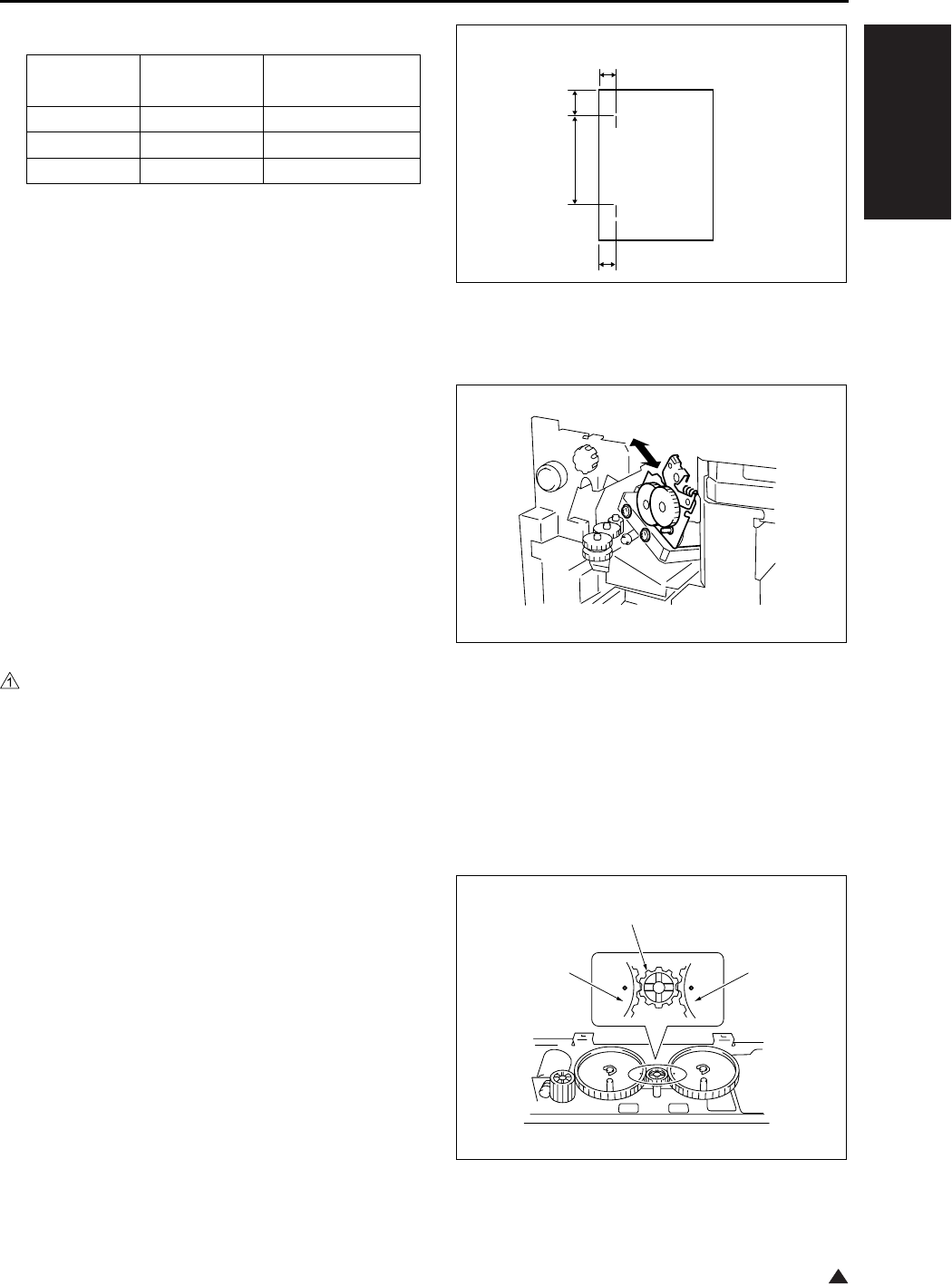
I ADJUSTMENT
OTHER ADJUSTMENTS
1-109
1
• 2-Point Staple
Y = (paper width-x-11) / 2
X = A3, A4: 137
B4, B5: 114
A4R: 190
B5R: 162
Substitute above into the equation.
3. If the staple position is misaligned, remove one
screw and the cover.
4. Loosen two adjustment screws and move the
Stapler Unit in the direction of the arrow to make
the adjustment.
5. Make another copy and check the staple posi-
tion.
10.15 Adjustment of the Installa-
tion Position of the Shutter
Drive Gear of FS-114
• When the gear/1, 2 or 3 is replaced, or the gear/
1, 2 or 3 is removed.
A. Procedure
1. Set three gears.
Note:
• Set the gears so that the marks on Gears 1 and 3
are aligned with the rib of Gear 2 as shown on the
right.
Measurement
position
Specification Adjustment range
C, F 6.0 ± 4mm +1mm to -2mm
DY ± 4mm—
EX ± 4mm—
4349D505AA
C
D
E
F
4349D513AA
4349D502AA
Gear 1
Gear 2
Gear 3
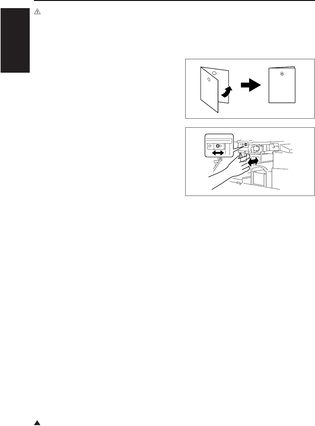
I ADJUSTMENT
OTHER ADJUSTMENTS
1-110
1
10.16 Punch Hole Deviance Adjust-
ment of FS-114 (PK-114)
• When the punch kit is replaced or removed.
A. Procedure
1. Set the copier into the Hole Punch mode and
make a 1-sided copy from a 1-sided original.
2. Fold the output paper in half and check whether
the punch hole positions are aligned.
Specification: Within 2mm
3. If the punch hole position is misaligned, remove
two screws and the cover.
4. Loosen one adjustment screw and move the
Punch Unit forward or backward to make the
adjustment.
5. Make another copy and check the punch hole
position.
4349D501AA
4512U025AB

I ADJUSTMENT
OTHER ADJUSTMENTS
1-111
1
10.17 Fold Angle Adjustment of
SK-114
• It is performed when the fold unit is replaced or a
tilt occurs in paper folding.
A. Procedure
1. Enter the Crease mode and make a copy. (A3
Size)
2. Fold the output paper and half and check
whether section A of the paper is aligned.
Specification: 0 ± 1.5mm
3. If the fold position is slanted as shown on the
left, make the following adjustment.
4. Open the Front Door, loosen one adjustment
screw, and move the Crease Unit to the left to
make the adjustment.
* If the fold position is slanted opposite to the
figure of step 3, move the Crease Unit to the
right to make the adjustment.
5. Make another copy and check the fold position.
A
4511D529AA
Center
Fold
4511D530AA
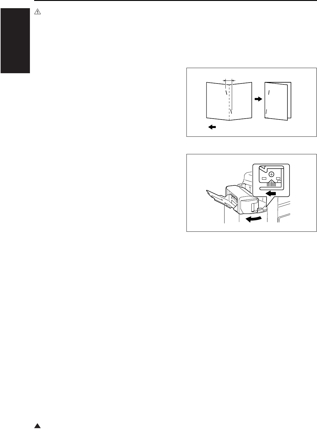
I ADJUSTMENT
OTHER ADJUSTMENTS
1-112
1
10.18 Staple Angle Adjustment of
SK-114
• It is performed when the staple unit 1 or 2 is
replaced or a tilt occurs in center staple position.
A. Procedure
1. Set five A4 originals in the ADF.
2. Set to 2-point Staple and Crease mode and
make a copy. Check whether the staple position
is aligned correctly.
Specification: 0 ± 1.5mm
3. If the staple position is slanted as shown on the
figure, make the following adjustment.
4. Release the lock release lever of the Saddle
Unit.
5. Loosen one adjustment screw and move the
lock lever to the left to make the adjustment.
* If the staple position is slanted opposite to the
figure of step 3, move the lock lever to the
right to make the adjustment.
6. Make another copy and check the staple posi-
tion.
A
4511D531AA
Exit direction
4511D532AA

II ISW
DESCRIPTION OF THE ISW
2-1 3
II ISW
1. DESCRIPTION OF THE ISW
The ISW (In-System Writer) is an operation by
which the control program, that is stored in the flash
ROM incorporated into a variety of control boards in
the digital copier, is rewritten with the board inte-
grated into the main body of the copier. Executing
the ISW allows you to renew the version of the con-
trol program without changing the board or to install
the latest program while changing the board.
As a tool to execute the ISW, you can use the [ISW
Trns (PC software)] by which rewriting is made with
a personal computer (PC) connected to the digital
copier.
This tools allow direct rewriting of the control pro-
gram in the flash ROM included in the copier main
body by connecting the ISW connector of the copier
main body.
The method of carrying out the necessary setup
work on the main body for executing ISW is
described here. For the operation of the “ISW Trns,”
see the “ISW (In-System Writer) Service Manual.”
Note:
• When using the USB, be sure to turn on the USB
radio button in the [Setting (S)] - [Communication
setting (C)] of the ISWTrns and press the OK but-
ton.
• For the ISW method of this machine, only the
ISW Trns is available.
2. SETUP
A. Board used for the ISW
The following boards are available for rewriting
a program using the ISW in this machine.
• SCB (System control board)
• CB (Main body control board)
• FNSCB (FNS control board) : FS-112
• PWB-A FN (Main control board) : FS-114
• FAX control
• For the printer controller, see the Service Manual
of IP.
For boards other than the above, the ROM is
required to be changed.
B. Data flow
There are 2 types of data flows for the ISW as
shown below:
•PC→SCB→CB→FNSCB/PWB-A FN
•PC→SCB→FAX
Important:
• When the overall control program has not been
written into the SCB (System control board), it is
not possible to rewrite programs for other boards.
C. Checking before transfer
Before executing the ISW, be sure to check to
see if the transfer case and the transfer mode
to be used are correct.
(1) When the overall control program has not
been installed
When the overall control program has not been
installed, the LCD screen is not displayed and
data cannot be written in the 25 mode.
Transfer case: When the SCB (System control
board) is being replaced.
Transfer mode:When the power is on. (When
the data LED indicator lamp is
on → The ISW is waiting for
transfer. When the lamp is
flashing → The ISW is receiving
data.)
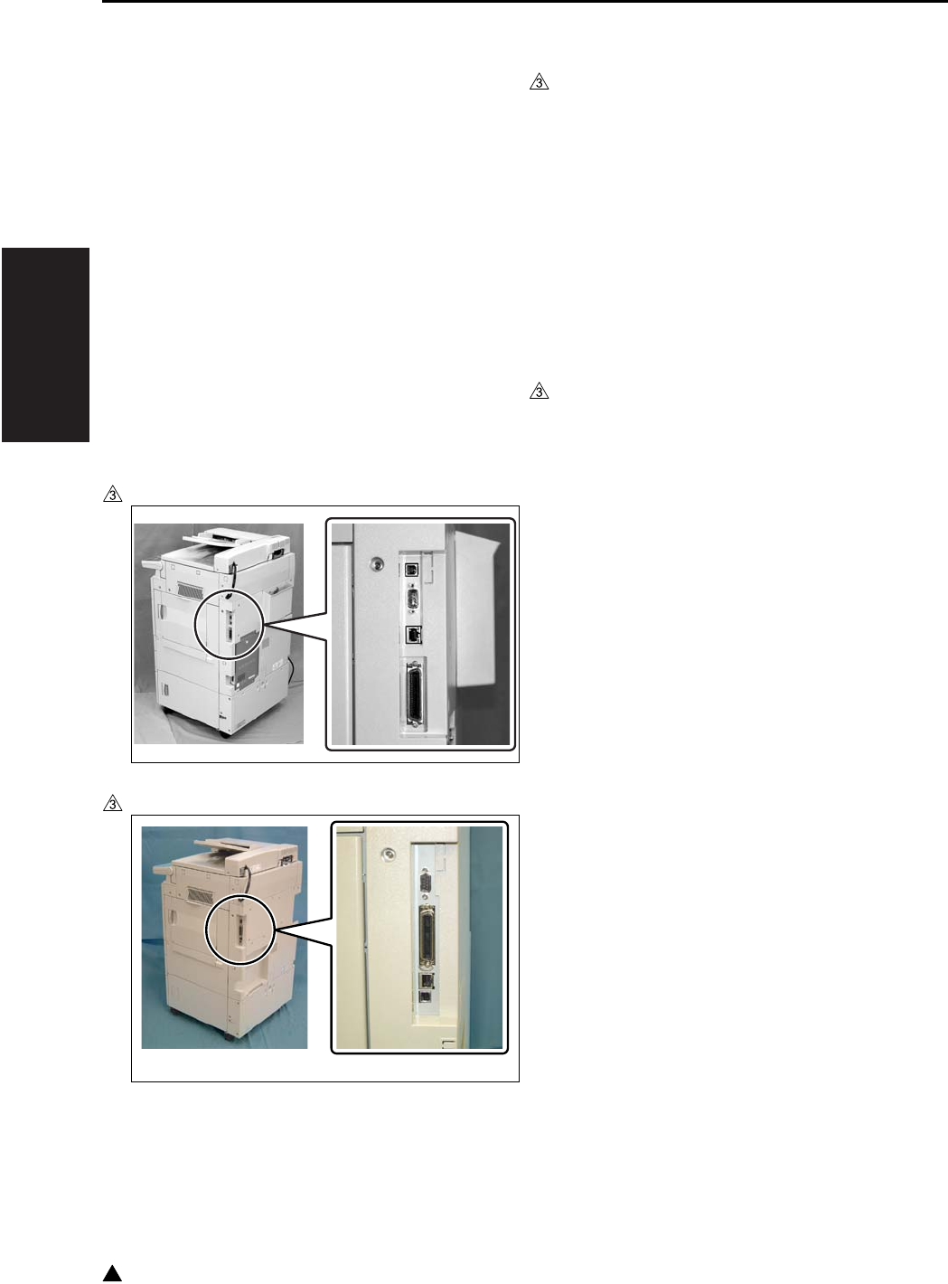
II ISW
SETUP
2-2
3
(2) When the overall control program has been
installed
When the overall control program has been
installed, it is possible to write data in the 25
mode.
Transfer case: Version up, when boards other
than the SCB (System control
board) are being replaced.
Transfer mode:25 mode
D. ISW connectors
The ISW connectors are provided on the right
side of the main body, and each of the connec-
tors is covered with a cap or seal. Be sure to
remove this cap or seal while in use.
The following two types of IF are available:
• USB (B type)
• IEEE1284 (Nibble/ECP/compatible mode)
In the case of the 7145
In the case of the 7235/7228/7222
E. Preparation of the copying machine for ISW
transfer
When the copier and the PC are USB con-
nected for the first time, it is necessary to install
the USB driver into the PC. (It is not required,
however, to install the USB driver on and after
the second connection.)
For details of the installation procedure of the
USB driver, see “3. USB ISW.”
Before operating the ISW, maintain the copier
in ISW mode.
(1) When the overall control program has been
installed
a. Procedure
1. Enter the 25 mode.
2. “25 mode menu screen”
Press the [10.ISW] key.
3. “ISW menu screen”
Select the ROM where the ROM data to be
rewritten.
[START] key is displayed.
4. “Program rewrite screen”
Press the [START] key.
Note:
• This step is to be used only when carrying out the
ISW to make a USB connection. When a connec-
tion method other than the above is used, pro-
ceed to Step 6.
5. “Program rewrite screen”
After confirming that a message “Reading pro-
gram data” is to be displayed, disconnect once
the USB cable that has been connected to the
copier and then reconnect it again.
Note:
• The step is to be used only when carrying out the
ISW to make a USB connection. When a connec-
tion method other than the above is used, pro-
ceed to Step 6.
6. “Program rewrite screen”
Pressing [START] key, cause the machine to be
data waiting condition.
7322fs2001

II ISW
SETUP
2-3 3
Note:
• When the ISW is carried out to make a USB con-
nection, this step should be omitted.
7. Execute the operation according to the proce-
dures specified in the “ISW (In-System Writer)
Service Manual.”
8. In about 60 seconds after the data transfer from
the PC has been completed, the ISW data is
written from the system memory in the SCB
(System control board) into the flash ROM in
which data is stored.
Note:
• When Steps 4 and 5 are not carried out to make a
USB connection, the USB port is not opened and
the data cannot be sent from the PC. When the
normal operation of the ISW is not available, start
all over again from Step 1 after turning the SW1
(main switch) OFF and ON.
• Be sure not turn off the power to the copying
machine while the ISW data is being written.
9. When data has been written into the flash ROM,
the system is restarted to display the “25 mode
menu screen.”
(2) When the overall control program is not
installed
1. Turn on the SW1 (Main power switch) and the
SW2 (Sub-power switch).
2. Check to see if the data LED indicator lamp is
on. In this condition, the ISW is placed in waiting
for transfer.
Check to see if the data LED is flashing while
the ISW data is being received.
3. The procedure after this is the same as the
steps above for “(1) When the overall control
program has been installed”.
F. Data transfer error
When a transfer error occurs, an error mark is
displayed in the message area on the LCD dis-
play.
If an error occurs, see the section “Error han-
dling” in the separate “ISW Service Manual”
and perform the appropriate countermeasures.
After the countermeasures are completed, per-
form the re-write operation again from the
beginning.
(1) ISW for image control/FNS control/FAX con-
trol
a. Procedure
1. Enter the 25 mode.
2. “25 mode menu screen”
Press the [10. ISW] key.
3. “ISW menu screen”
Select a ROM the data of which is rewritten. The
[START] key is displayed.
4. “Program rewrite screen”
Press the [START] key.
Note:
• This step is to be used only when carrying out the
ISW to make a USB connection. When a connec-
tion method other than the above is used, pro-
ceed to Step 6.
5. “Program rewrite screen”
After confirming that a message “Reading pro-
gram data” is to be displayed, connect the USB
cable.
Note:
• The step is to be used only when carrying out the
ISW to make a USB connection. When a connec-
tion method other than the above is used, pro-
ceed to Step 6.
6. “Program rewrite screen”
Press the [START] key to put the ISW into the
state of waiting for transfer.

II ISW
SETUP
2-4
3
Note:
• When the ISW is carried out to make a USB con-
nection, this step should be omitted.
7. Execute the operation according to the proce-
dure given in the ISW (In-system Writer) Service
Manual.
8. In about 100 seconds after completion of the
transfer of data from the PC, the ISW data is
written into the flash ROM in the ISW-intended
board.
Note:
• When Steps 4 and 5 are not carried out to make a
USB connection, the USB port is not opened and
the data cannot be sent from the PC. When the
normal operation of the ISW is not available, start
all over again from Step 1 after turning the SW1
(main switch) OFF and ON.
• Do not turn off the power to the copying machine
while the ISW data is being written.
9. When the data has been written into the flash
ROM, a message “Completed successfully” is
displayed.
10. Press the [RETURN] key twice to return to the
“25 mode menu screen”.
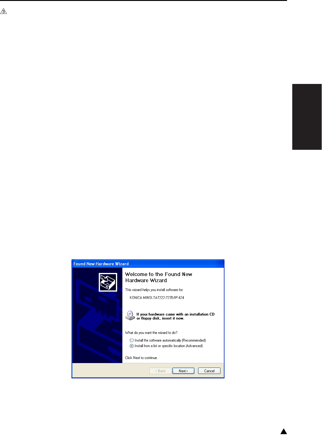
II ISW
USB ISW
2-5 3
3. USB ISW
The ISW RNs tool for transfer can be installed in the PC by using the setup disk. However, the USB driver
(KCAUSB.SYS) is required to be installed by the plug-and-play of the Windows after connecting the PC and
the copier with the USB cable.
The installation of the USB driver is required only when the PC is connected to the copier for the first time.
(No installation is required on and after the second connection.)
A. Preparation for the installation of the USB driver
1. Enter the 25 mode.
2. “25 mode menu screen”
Press the [10.ISW] key.
3. “ISW menu screen”
Select the ROM where the ROM data to be rewritten.
[START] key is displayed.
4. “Program rewrite screen”
Pressing [START] key causes the machine to be data waiting condition.
5. Connect the USB connector.
• The “Welcome to the Found New Hardware Wizard” display is shown.
(The succeeding steps of the “B. USB driver installation procedure (Windows 2000/XP)”).
B. USB driver installation procedure (Windows 2000/XP)
When the PC and the copier are connected with the USB cable, the USB driver is automatically installed by
the plug-and-play.
However, this may cause the USB driver (USBPRINT.SYS) of the Windows to be installed. Accordingly, the
USB driver should be set by following the procedure given below:
1. Select “Install from a list or specific location [Advanced]” in the display shown below, and then click
[Next].
2. Select “Display a list of the known drivers for this device so that I can choose a specific driver” in the
“Install Hardware Device Drivers” screen, and then click [Next].
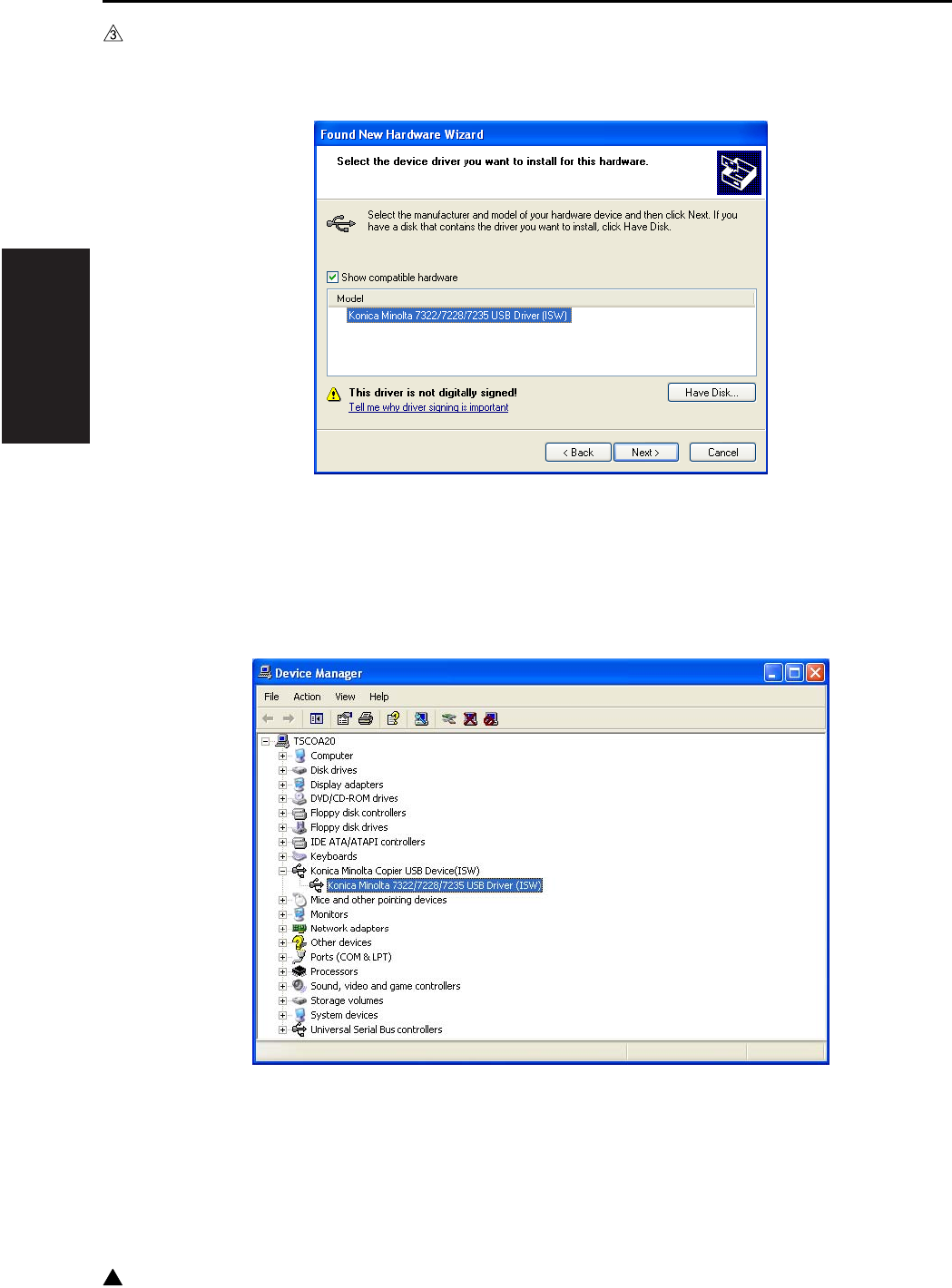
II ISW
USB ISW
2-6
3
3. Select the USB driver in the driver selection screen, and then click [Next] for installation.
• In the case of the 7145 : Konica Minolta 7145 USB Driver (ISW)
• In the case of the 7235/7228/7222 : Konica Minolta 7222/7228/7235 USB Driver (ISW)
4. When the “Completing the Upgrade Device Driver Wizard” screen is displayed, click [Finish] to finish the
installation.
5. In the “Device Manager” screen, check to see if the installation of the USB driver is carried out correctly.
• In the case of the 7145 : Konica Minolta 7145 USB Driver (ISW)
• In the case of the 7235/7228/7222 : Konica Minolta 7222/7228/7235 USB Driver (ISW)

III SERVICE
SERVICE SCHEDULE
3-1 3
III SERVICE
1. SERVICE SCHEDULE
1.1 Service Schedule
1.1.1 7145
Service item x 10,000 copies
12 24 36 48 60 72 84 96 108 120 132 144 156 168 180
Main
body
Maintenance
Every 120,000
copies
zzzzzzzzzzzzzz
Periodic check (I)
Every 240,000
copies
zzzzzzz
Periodic check (II)
Every 360,000
copies
zzzz
Periodic check (III)
Every 480,000
copies
zzz
Periodic check (IV)
Every 720,000 cop-
ies
zz
DF-318
Maintenance
Every 120,000
copies
zzzzzzzzzzzzzz
Periodic check (I)
Every 960,000
copies
z
Periodic check (II)
Every 1,200,000
copies
z
DB-411
Maintenance
Every 120,000
copies
zzzzzzzzzzzzzz
Periodic check (I)
Every 240,000
copies
zzzzzzz
DB-211
Maintenance
Every 120,000
copies
zzzzzzzzzzzzzz
Periodic check (I)
Every 480,000
copies
zzz

III SERVICE
SERVICE SCHEDULE
3-2
3
1.1.2 7235
LT-203
Maintenance
Every 120,000
copies
zzzzzzzzzzzzzz
Periodic check (I)
Every 240,000
copies
zzzzzzz
FS-112
Maintenance
Every 120,000
copies
zzzzzzzzzzzzzz
Periodic check (I)
Every 600,000
copies
zz
FS-113+RU-101
Maintenance
Every 120,000
copies
zzzzzzzzzzzzzz
FS-114/PK-114
SK-114/BK-114
Maintenance
Every 120,000
copies
zzzzzzzzzzzzzz
Service item x 10,000 copies
12 24 36 48 60 72 84 96 108 120 132 144 156 168 180
Service item x 10,000 copies
10 20 30 40 50 60 70 80 90 100 110 120
Main
body
Maintenance
Every 100,000
copies
zzzzzzzzzzz
Periodic check (I)
Every 200,000
copies
zzzzz
Periodic check (II)
Every 300,000
copies
zzz
Periodic check (III)
Every 400,000
copies
zz
Periodic check (IV)
Every 600,000 cop-
ies
z
DF-320
Maintenance
Every 100,000
copies
zzzzzzzzzzz
Periodic check (I)
Every 1,000,000
copies
z
DB-411
Maintenance
Every 100,000
copies
zzzzzzzzzzz
Periodic check (I)
Every 200,000
copies
zzzzz
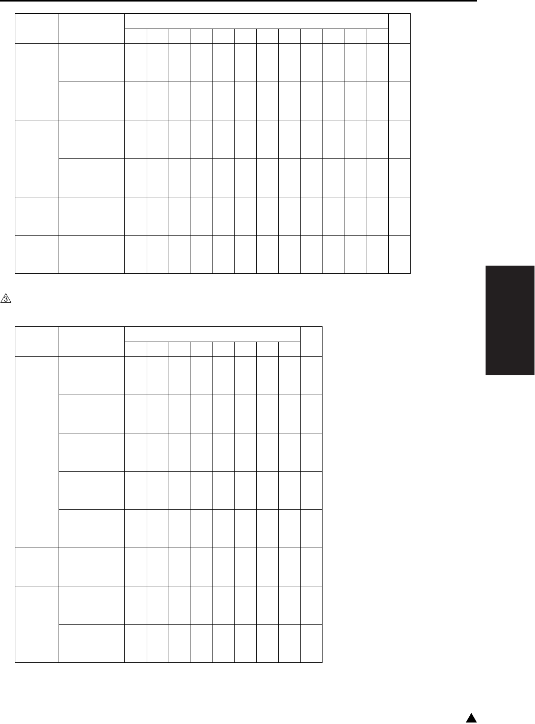
III SERVICE
SERVICE SCHEDULE
3-3 3
1.1.3 7228/7222
DB-211
Maintenance
Every 100,000
copies
zzzzzzzzzzz
Periodic check (I)
Every 400,000
copies
zz
LT-203
Maintenance
Every 100,000
copies
zzzzzzzzzzz
Periodic check (I)
Every 400,000
copies
zz
FS-113+RU-101
Maintenance
Every 100,000
copies
zzzzzzzzzzz
FS-114/PK-114
SK-114/BK-114
Maintenance
Every 100,000
copies
zzzzzzzzzzz
Service item x 10,000 copies
10 20 30 40 50 60 70 80 90 100 110 120
Service item x 10,000 copies
10 20 30 40 50 60 70 80
Main
body
Maintenance
Every 100,000
copies
zzzzzzz
Periodic check (I)
Every 200,000
copies
zzz
Periodic check (II)
Every 300,000
copies
zz
Periodic check (III)
Every 400,000
copies
z
Periodic check (IV)
Every 600,000 cop-
ies
z
DF-320
Maintenance
Every 100,000
copies
zzzzzzz
DB-411
Maintenance
Every 100,000
copies
zzzzzzz
Periodic check (I)
Every 200,000
copies
zzz
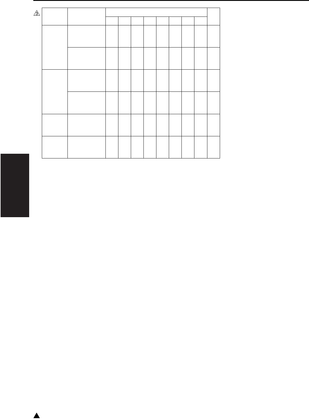
III SERVICE
SERVICE SCHEDULE
3-4
3
DB-211
Maintenance
Every 100,000
copies
zzzzzzz
Periodic check (I)
Every 400,000
copies
z
LT-203
Maintenance
Every 100,000
copies
zzzzzzz
Periodic check (I)
Every 400,000
copies
z
FS-113+RU-101
Maintenance
Every 100,000
copies
zzzzzzz
FS-114/PK-114
SK-114/BK-114
Maintenance
Every 100,000
copies
zzzzzzz
Service item x 10,000 copies
10 20 30 40 50 60 70 80

III SERVICE
SERVICE SCHEDULE
3-5 3
1.2 Maintenance Items
1.2.1 7145
Every 120,000 copies/prints
No.
Classification
Service item Quantity Implementation classification Materials•Tools
used
Cleaning Check
Lubrication
Replacement
1
Preparations
(1) Image check z
(2) Exterior z
2 Fixing unit (1) Removal of fixing unit
3 Main body (1) Suction filter/A 1 z
(2) Filter cover assembly 1 z
(3) Cooling fan/1 (FM4)
Cooling fan/2 (FM7)
Inlet filter
Developing suction/F, /R
zz
Blower brush
4 Read unit (1) Platen glass
(include the slit glass) zDrum cleaner/
Cleaning pad
(2) No. 1 to No. 3 mirrors zDrum cleaner/
Cleaning pad
5 Paper
feed unit
(1) Paper feed roller zDrum cleaner/
Cleaning pad
(2) Feed roller zDrum cleaner/
Cleaning pad
(3) Double feed
prevention roller zDrum cleaner/
Cleaning pad
(4) Paper dust removing
brush zBlower brush/
Cleaning pad
6 Bypass
feed unit
(1) Double feed preven-
tion roller zDrum cleaner/
Cleaning pad
(2) Paper feed roller zDrum cleaner/
Cleaning pad
(3) Feed roller zDrum cleaner/
Cleaning pad
7 Fixing unit (1) Fixing claw zDrum cleaner/
Cleaning pad
(2) Fixing sensor zDrum cleaner/
Cleaning pad
(3) Fixing thermostat zDrum cleaner/
Cleaning pad
(4) Fixing heat roller 1 z
(5) Fixing press roller 1 z
(6)
Heat insulating sleeve/A
2zz
Solvest 240 or
Multemp FF-RM
(7)
Heat insulating sleeve/B
1z
(8) Fixing idling gear/B 1 zz
Drum cleaner/
Cleaning pad
(9) Install of fixing unit

III SERVICE
SERVICE SCHEDULE
3-6
3
1.2.2 7235/7228/7222
Every 100,000 copies/prints
8
Final check
(1) Loading of toner car-
tridge z
(2) Check of W.U.T z
(3) Check of image
adjustment z
(4)
Check of copy samples
z
(5) 25 mode PM counter
resetting z
(6)
Peripheral and exterior
of the machine
zDrum cleaner/
Cleaning pad
Note:
• The inlet filters for the FM4/FM7 may get soiled depending on the location in which the machine is placed.
Be sure to clean it when the filter is found clogged with dust while in inspection.
When cleaning is not made properly, toner packing may result due to a temperature rise inside the
machine.
No.
Classification
Service item Quantity Implementation classification Materials•Tools
used
Cleaning Check
Lubrication
Replacement
No.
Classification
Service item Quantity Implementation classification Materials•Tools
used
Cleaning Check
Lubrication
Replacement
1
Preparations
(1) Image check z
(2) Exterior z
2 Main body (1) Suction filter/A 1 z
(2) Filter cover assembly 1 z
(3) Cooling fan/1 (FM4)
Inlet filter zz Blower brush
(4)
Developing suction/F, /R
z
3 Read unit (1) Platen glass
(include the slit glass) zDrum cleaner/
Cleaning pad
(2) No. 1 to No. 3 mirrors zDrum cleaner/
Cleaning pad
4 Paper
feed unit
(1) Paper feed roller zDrum cleaner/
Cleaning pad
(2) Feed roller zDrum cleaner/
Cleaning pad
(3) Double feed
prevention roller zDrum cleaner/
Cleaning pad
(4) Paper dust removing
brush zBlower brush/
Cleaning pad
5 Bypass
feed unit
(1) Double feed preven-
tion roller zDrum cleaner/
Cleaning pad
(2) Paper feed roller zDrum cleaner/
Cleaning pad
(3) Feed roller zDrum cleaner/
Cleaning pad
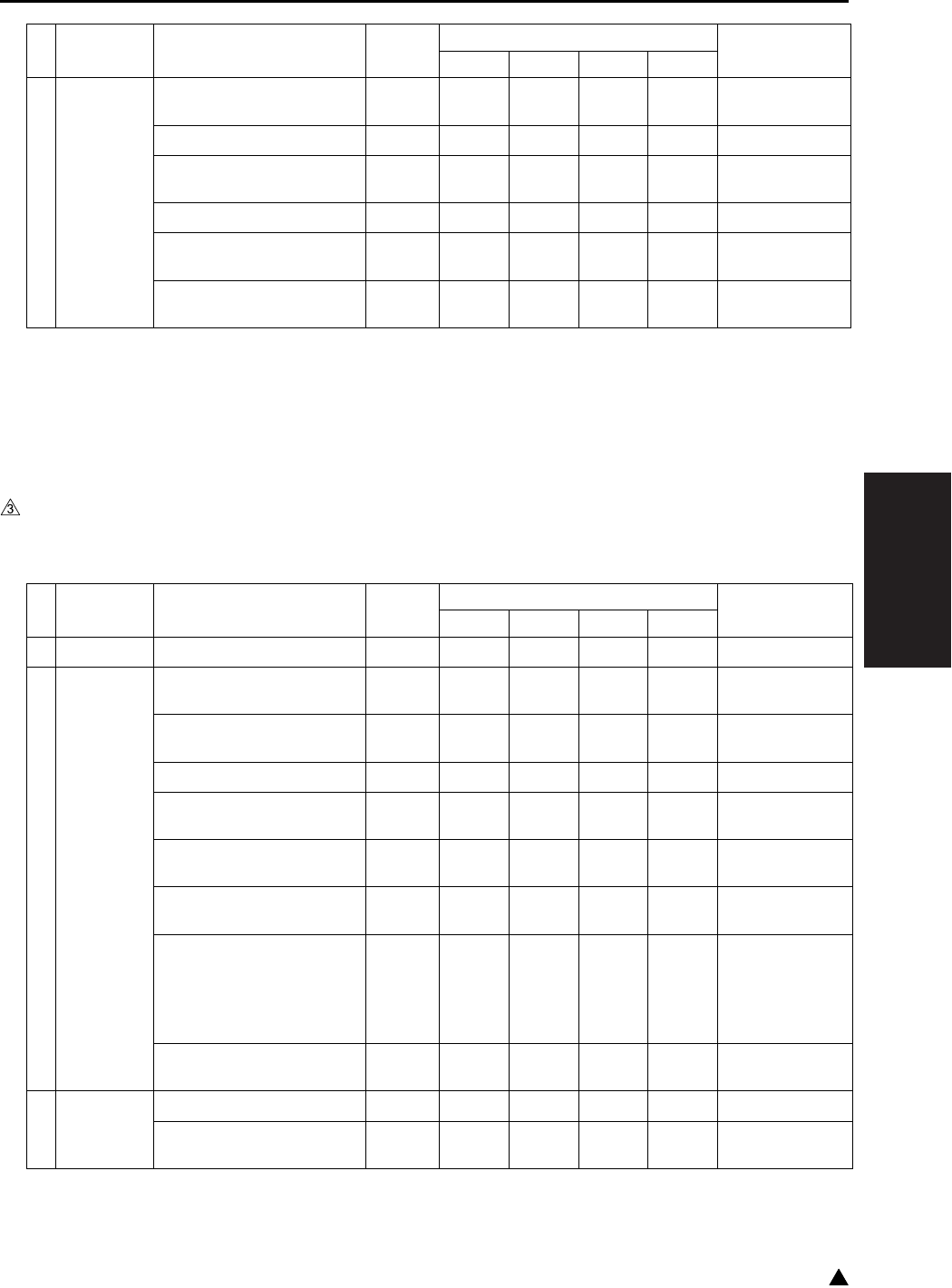
III SERVICE
SERVICE SCHEDULE
3-7 3
1.2.3 DF-318/320
Every 120,000 copies/prints (7145)
Every 100,000 copies/prints (7235/7228/7222)
6
Final check
(1) Loading of toner car-
tridge z
(2) Check of W.U.T z
(3) Check of image
adjustment z
(4)
Check of copy samples
z
(5) 25 mode PM counter
resetting z
(6)
Peripheral and exterior
of the machine
zDrum cleaner/
Cleaning pad
Note:
• The inlet filters for the FM4 may get soiled depending on the location in which the machine is placed. Be
sure to clean it when the filter is found clogged with dust while in inspection.
When cleaning is not made properly, toner packing may result due to a temperature rise inside the
machine.
No.
Classification
Service item Quantity Implementation classification Materials•Tools
used
Cleaning Check
Lubrication
Replacement
No.
Classification
Service item Quantity Implementation classification Materials•Tools
used
Cleaning Check
Lubrication
Replacement
1
Preparations
(1) Paper through check z
2
Paper feed
section
(1) Original registration
sensor zBlower brush
(2) Original conveyance
sensor zBlower brush
(3)
Original size sensor/1, /2
zBlower brush
(4) Paper feed roller zDrum cleaner/
Cleaning pad
(5) Feed roller zDrum cleaner/
Cleaning pad
(6)
Double feed prevention
roller
zDrum cleaner/
Cleaning pad
(7) Read roller
z
Water/
Cleaning pad
Note:
• Do not use
alcohol.
(8) Paper dust removing
brush zBlower brush
3
Final check
(1) Paper through check z
(2) Exterior cleaning zDrum cleaner/
Cleaning pad

III SERVICE
SERVICE SCHEDULE
3-8
3
1.2.4 DB-211/411
Every 120,000 copies/prints (7145)
Every 100,000 copies/prints (7235/7228/7222)
1.2.5 LT-203
Every 120,000 copies/prints (7145)
Every 100,000 copies/prints (7235/7228/7222)
1.2.6 FS-112
Every 120,000 copies/prints (7145 only)
No.
Classification
Service item Quantity Implementation classification Materials•Tools
used
Cleaning Check
Lubrication
Replacement
1
Preparations
(1) Paper through check z
2
Paper feed
section
(1) Paper feed roller zDrum cleaner/
Cleaning pad
(2) Feed roller zDrum cleaner/
Cleaning pad
(3) Double feed
prevention roller zDrum cleaner/
Cleaning pad
3
Final check
(1) Paper through check z
(2) Exterior cleaning zDrum cleaner/
Cleaning pad
No.
Classification
Service item Quantity Implementation classification Materials•Tools
used
Cleaning Check
Lubrication
Replacement
1
Preparations
(1) Paper through check z
2
Conveyance
section
(1) Conveyance drive
roller/A zDrum cleaner/
Cleaning pad
(2) Paper exit drive roller zDrum cleaner/
Cleaning pad
3
Final check
(1) Paper through check z
(2) Exterior cleaning zDrum cleaner/
Cleaning pad

III SERVICE
SERVICE SCHEDULE
3-9 3
1.2.7 FS-113/RU-101
Every 120,000 copies/prints (7145)
Every 100,000 copies/prints (7235/7228/7222)
1.2.8 FS-114
Every 120,000 copies/prints (7145)
Every 100,000 copies/prints (7235/7228/7222)
1.2.9 PK-114
Every 120,000 copies/prints (7145)
Every 100,000 copies/prints (7235/7228/7222)
No.
Classification
Service item Quantity Implementation classification Materials•Tools
used
Cleaning Check
Lubrication
Replacement
1
Preparations
(1) Paper through check z
2 FS-113 (1) Each of conveyance
rollers zDrum cleaner/
Cleaning pad
(2) Paddle zDrum cleaner/
Cleaning pad
(3) Punch scraps box
section zCleaning pad
3 RU-101 (1) Each of conveyance
rollers z
(2) Exterior z
4
Final check
(1) Paper through check z
(2) Exterior cleaning zDrum cleaner/
Cleaning pad
No.
Classification
Service item Quantity Implementation classification Materials•Tools
used
Cleaning Check
Lubrication
Replacement
1
Preparations
(1) Paper through check z
2
Conveyance
section
(2) Each of conveyance
rollers zDrum cleaner/
Cleaning pad
3
Alignment
section
(1) Paddle zDrum cleaner/
Cleaning pad
4
Final check
(1) Paper through check z
(2) Exterior cleaning zDrum cleaner/
Cleaning pad
No.
Classification
Service item Quantity Implementation classification Materials•Tools
used
Cleaning Check
Lubrication
Replacement
1
Conveyance
section
(1) Each of conveyance
rollers zDrum cleaner/
Cleaning pad
2
Punch
scraps box
(2) Cleaning the punch
scraps box z

III SERVICE
SERVICE SCHEDULE
3-10
3
1.2.10 SK-114
Every 120,000 copies/prints (7145)
Every 100,000 copies/prints (7235/7228/7222)
1.2.11 BK-114
Every 120,000 copies/prints (7145)
Every 100,000 copies/prints (7235/7228/7222)
No.
Classification
Service item Quantity Implementation classification Materials•Tools
used
Cleaning Check
Lubrication
Replacement
1
Conveyance
section
(1) Each of conveyance
rollers zDrum cleaner/
Cleaning pad
2Exterior
section
(2) Exterior cleaning zDrum cleaner/
Cleaning pad
No.
Classification
Service item Quantity Implementation classification Materials•Tools
used
Cleaning Check
Lubrication
Replacement
1 Tray (1) Tray stack surface zDrum cleaner/
Cleaning pad
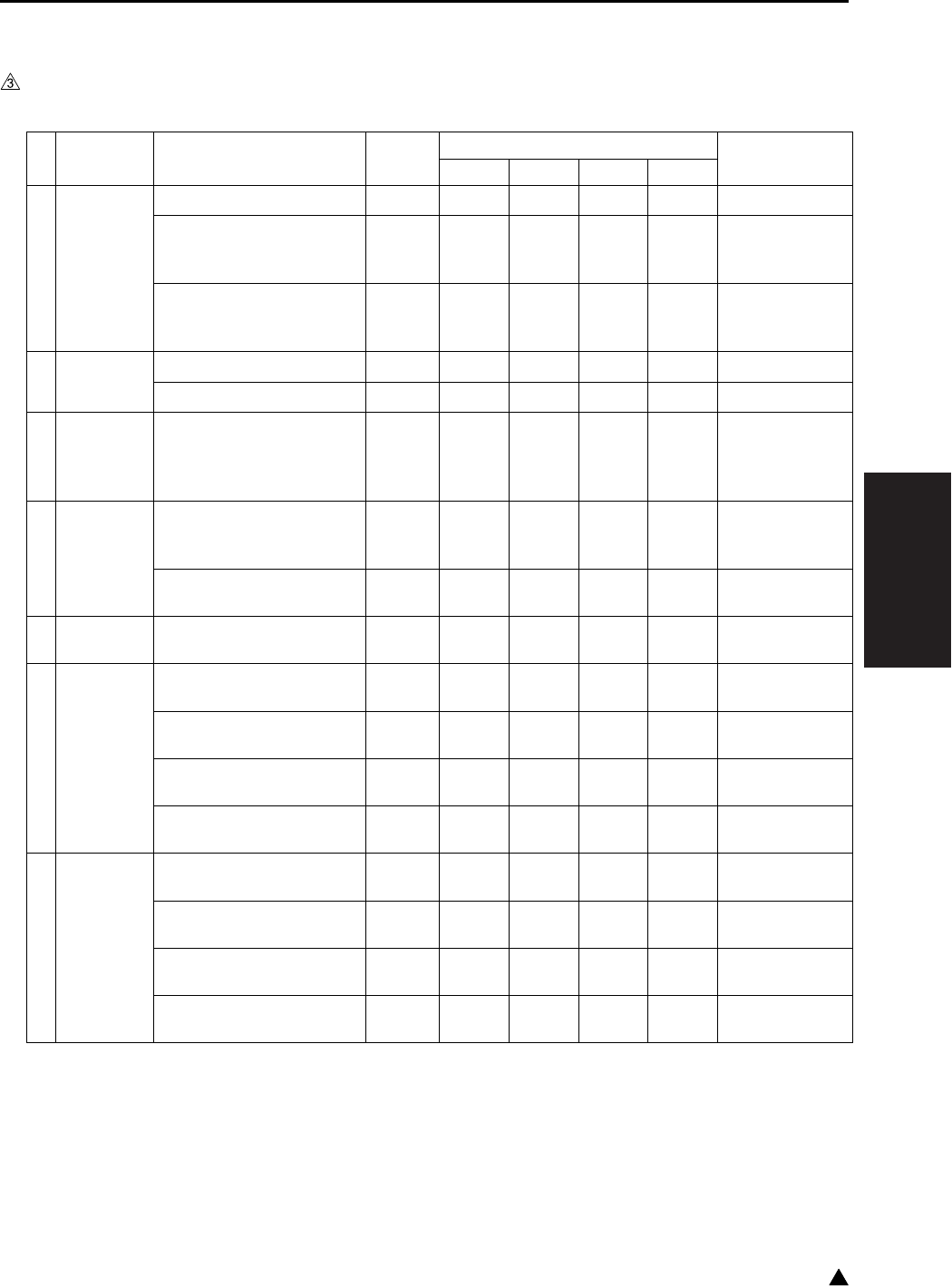
III SERVICE
SERVICE SCHEDULE
3-11 3
1.3 Periodic Check Items
1.3.1 7145
A. Periodic check (I) (Every 240,000 copies/prints)
No.
Classification
Service item Quantity Implementation classification Materials•Tools
used
Cleaning Check
Lubrication
Replacement
1 Drum unit (1) Drum 1 zSetting powder
(2) Cleaning blade
assembly
26TA-209∗
1
z
(3) 25 mode or 36 mode
Photosensitive
counter reset
z
2
Charging
corona unit
(1) Charging corona wire zCotton swab
(2) Changing control plate zCleaning pad
3
Transfer/
separation
corona unit
(1) Discharge wire
z
Cotton swab
(2 pcs.: 1 for
each of transfer
and separation)
4
Develop-
ing unit
(1) Developer
Developing unit
installing
1
z
(2) 36 mode L detection
adjustment z
5 Main body (1) Ozone filter
40LA1017∗1z
6 Fixing unit (1)
Fixing cleaner assembly
40LA-540∗1z
(2) Fixing claw
26NA5427∗6z
(3) Fixing bearing /U
26NA5371∗2z
(4) Fixing bearing /L
26NA5359∗2z
7
Final check
(1) 25 mode or 36 mode
Fixing counter reset z
(2) 36 mode LD1 offset
adjustment z
(3) 36 mode LD2 offset
adjustment z
(4) Check of image
adjustment z
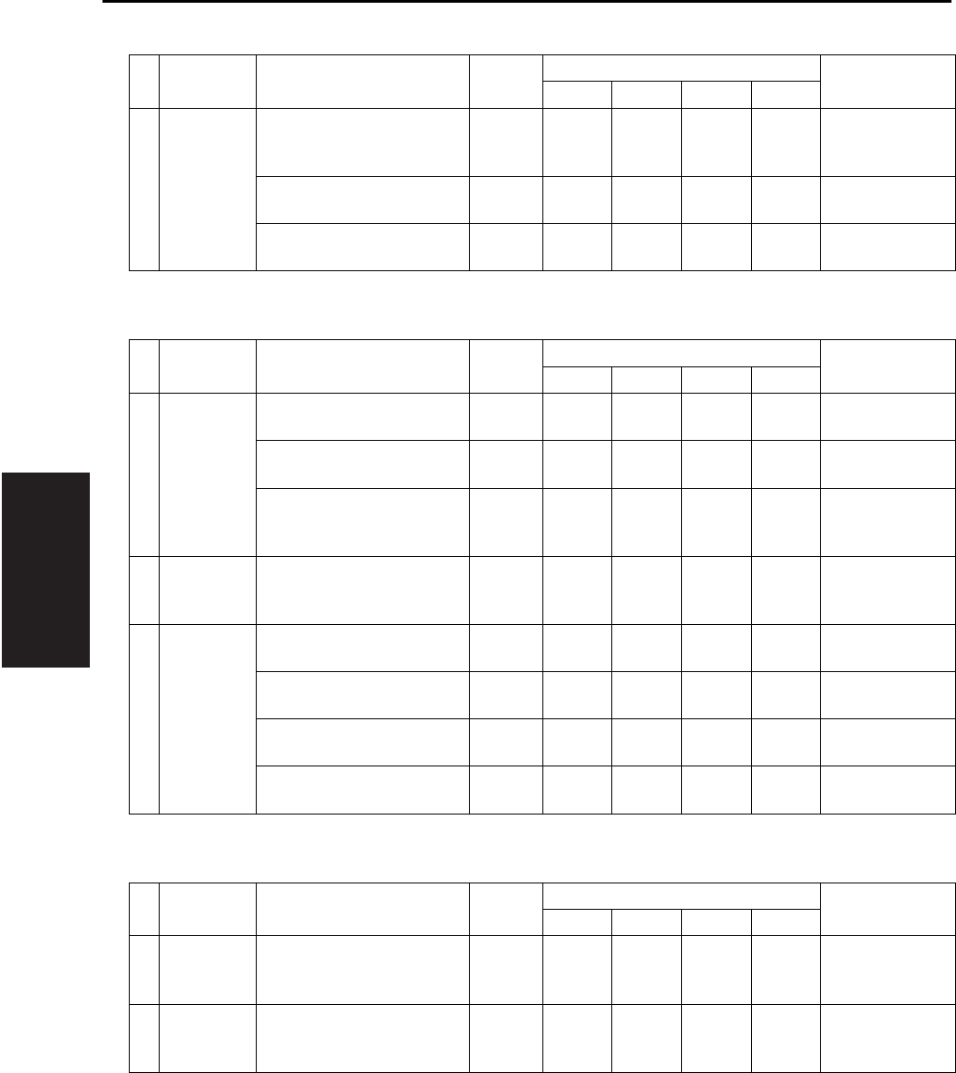
III SERVICE
SERVICE SCHEDULE
3-12
B. Periodic check (II) (Every 360,000 copies/prints)
C. Periodic check (III) (Every 480,000 copies/prints)
D. Periodic check (IV) (Every 720,000 copies/prints)
No.
Classification
Service item Quantity Implementation classification Materials•Tools
used
Cleaning Check
Lubrication
Replacement
1 Bypass
feed
(Paper feed
section)
(1) Double feed
prevention roller
40AA-406∗
1
z
Actual durable
count : 100,000
(2) Paper feed roller
26NA-428∗1zActual durable
count : 100,000
(3) Feed roller
40AA-425∗1zActual durable
count : 100,000
No.
Classification
Service item Quantity Implementation classification Materials•Tools
used
Cleaning Check
Lubrication
Replacement
1
Main body
paper feed unit
(1) Paper feed rubber
40LA4009∗2zActual durable
count : 200,000
(2) Feed rubber
26NA4011∗2zActual durable
count : 200,000
(3) Double feed
prevention rubber
26NA4012∗
2
z
Actual durable
count : 200,000
2
Transfer/
separation
corona unit
(1) Transfer corona unit
40LA-260∗1
z
3 Fixing unit (1)
Fixing sensor assembly
40LA-534∗1z
(2) Fuse mounting plate
SP00-0110
1z
(3) Fixing heater lamp/1
40LA8302∗1z
(4) Fixing heater lamp/2
40LA8303∗1z
No.
Classification
Service item Quantity Implementation classification Materials•Tools
used
Cleaning Check
Lubrication
Replacement
1
Develop-
ing unit
(1) Developing unit (Unit
without developer)
40LA-300∗
1
z
2 Drum unit (1) Drum unit (Unit with-
out drum)
40LA-990∗
1
z

III SERVICE
SERVICE SCHEDULE
3-13 3
1.3.2 7235/7228/7222
A. Periodic check (I) (Every 200,000 copies/prints)
No.
Classification
Service item Quantity Implementation classification Materials•Tools
used
Cleaning Check
Lubrication
Replacement
1 Drum unit (1) Drum 1 zSetting powder
(2) Cleaning blade
assembly
26TA-209∗
1
z
(3) 25 mode or 36 mode
Photosensitive
counter reset
z
2
Charging
corona unit
(1) Charging corona wire zCotton swab
(2) Changing control plate zCleaning pad
3
Transfer/
separation
corona unit
(1) Discharge wire
z
Cotton swab
(2 pcs.: 1 for
each of transfer
and separation)
4
Develop-
ing unit
(1) Developer
Developing unit
installing
1
z
(2) 36 mode L detection
adjustment z
5 Main body (1) Ozone filter
40LA1017∗1z
6 Fixing unit (1) Fixing heat roller
26NA5303∗1z
(2) Fixing pressure roller
27LA5304∗
1z
(3)
Fixing cleaner assembly
27LA-540*
1z
(4)
Heat insulating sleeve /A
26NA5372∗
2
zz
Solvest 240 or
Multemp FF-
RM
(5)
Heat insulating sleeve /B
26NA5373∗
1z
(6) Fixing claw
27NA5427∗
6z
(7) Fixing bearing /U
26NA5371∗
2z
(8) Fixing bearing /L
26NA5359∗
2z
(9) Fixing idling gear /B
27NA5394∗
1zz
Drum cleaner/
Cleaning pad
(10)Fixing sensor zDrum cleaner/
Cleaning pad
(11)Fixing thermostat zDrum cleaner/
Cleaning pad

III SERVICE
SERVICE SCHEDULE
3-14
3
B. Periodic check (II) (Every 300,000 copies/prints)
C. Periodic check (III) (Every 400,000 copies/prints)
7
Final check
(1) 25 mode or 36 mode
Fixing counter reset z
(2) 36 mode LD1 offset
adjustment z
(3) Check of image
adjustment z
No.
Classification
Service item Quantity Implementation classification Materials•Tools
used
Cleaning Check
Lubrication
Replacement
No.
Classification
Service item Quantity Implementation classification Materials•Tools
used
Cleaning Check
Lubrication
Replacement
1 Bypass
feed
(Paper feed
section)
(1) Double feed
prevention roller
40AA-406∗
1
z
Actual durable
count : 100,000
(2) Paper feed roller
26NA-428∗1zActual durable
count : 100,000
(3) Feed roller
40AA-425∗1zActual durable
count : 100,000
No.
Classification
Service item Quantity Implementation classification Materials•Tools
used
Cleaning Check
Lubrication
Replacement
1
Main body
paper feed unit
(1) Paper feed rubber
40LA4009∗2zActual durable
count : 200,000
(2) Feed rubber
26NA4011∗2zActual durable
count : 200,000
(3) Double feed
prevention rubber
26NA4012∗
2
z
Actual durable
count : 200,000
2
Transfer/
separation
corona unit
(1) Transfer corona unit
40LA-260∗1
z
3 Fixing unit (1)
Fixing sensor assembly
26WA-534∗1z
(2) Fuse mounting plate
SP00-0110
1z

III SERVICE
SERVICE SCHEDULE
3-15 3
D. Periodic check (IV) (Every 600,000 copies/prints)
1.3.3 DF-318
A. Periodic check (I) (Every 960,000 copies/prints)
B. Periodic check (II) (Every 1,200,000 copies/prints)
1.3.4 DF-320
A. Periodic check (I) (Every 1,000,000 copies/prints)
No.
Classification
Service item Quantity Implementation classification Materials•Tools
used
Cleaning Check
Lubrication
Replacement
1
Develop-
ing unit
(1) Developing unit (Unit
without developer)
27LA-300∗
1
z
2 Drum unit (1) Drum unit
(Unit without drum)
27LA-200∗
1
z
No.
Classification
Service item Quantity Implementation classification Materials•Tools
used
Cleaning Check
Lubrication
Replacement
1
Paper feed
section
(1) Feed rubber
12QV4034∗1zActual durable
count : 250,000
(2) Double feed
prevention roller
13GL-405∗
1
z
Actual durable
count : 250,000
No.
Classification
Service item Quantity Implementation classification Materials•Tools
used
Cleaning Check
Lubrication
Replacement
1
Paper feed
section
(1) Paper feed roller
13GL4011∗1zActual durable
count : 300,000
No.
Classification
Service item Quantity Implementation classification Materials•Tools
used
Cleaning Check
Lubrication
Replacement
1
Paper feed
section
(1) Paper feed roller
13GL4011∗
1z
(2) Feed rubber
12QV4034∗
1z
(3) Double feed
prevention roller
13GL-405∗
1
z
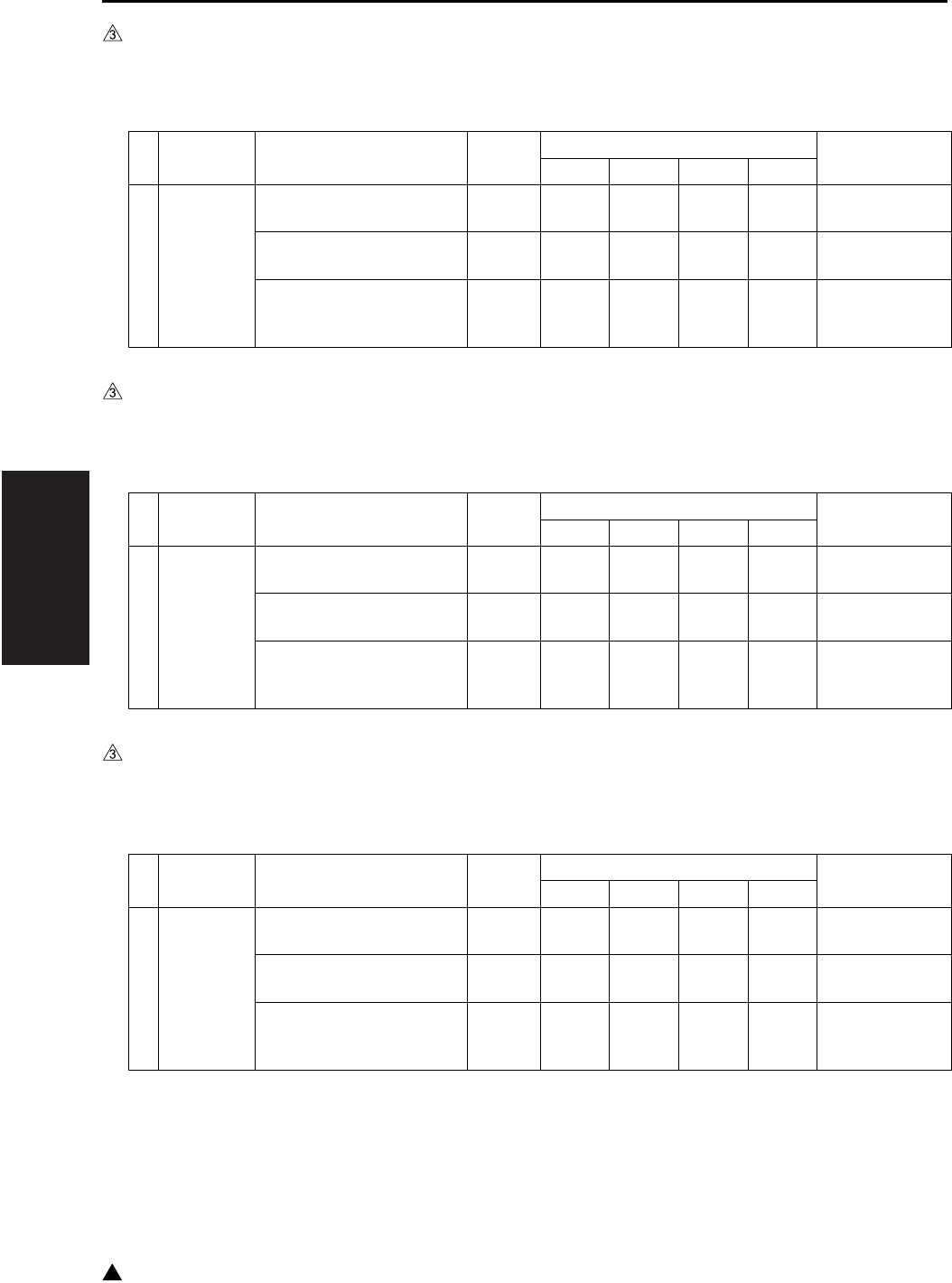
III SERVICE
SERVICE SCHEDULE
3-16
3
1.3.5 DB-211
A. Periodic check (I)
Every 480,000 copies/prints (7145)
Every 400,000 copies/prints (7235/7228/7222)
1.3.6 DB-411
A. Periodic check (I)
Every 240,000 copies/prints (7145)
Every 200,000 copies/prints (7235/7228/7222)
1.3.7 LT-203
A. Periodic check (I)
Every 240,000 copies/prints (7145)
Every 400,000 copies/prints (7235/7228/7222)
No.
Classification
Service item Quantity Implementation classification Materials•Tools
used
Cleaning Check
Lubrication
Replacement
1
Paper feed
section
(1) Paper feed rubber
40LA4009∗2zActual durable
count : 200,000
(2) Feed rubber
26NA4011∗2zActual durable
count : 200,000
(3) Double feed
prevention rubber
26NA4012∗
2
z
Actual durable
count : 200,000
No.
Classification
Service item Quantity Implementation classification Materials•Tools
used
Cleaning Check
Lubrication
Replacement
1
Paper feed
section
(1) Paper feed rubber
40LA4009∗1zActual durable
count : 200,000
(2) Feed rubber
26NA4011∗1zActual durable
count : 200,000
(3) Double feed
prevention rubber
26NA4012∗
1
z
Actual durable
count : 200,000

III SERVICE
SERVICE SCHEDULE
3-17 3
1.3.8 FS-112
A. Periodic check (I)
Every 600,000 copies/prints
No.
Classification
Service item Quantity Implementation classification Materials•Tools
used
Cleaning Check
Lubrication
Replacement
1
Exit section
(1) Paper exit roller /A
13GQ4519∗1zActual durable
count : 600,000

III SERVICE
SERVICE SCHEDULE
3-18
3
1.4 Replacement Parts List
No. Unit Parts name Parts No. Quantity Actual durable
count
01 DC (including changing
corona unit)
Drum — 1 240,000
(7145)
200,000
(7235/7228/7222)
02 Cleaning blade assembly 26TA-209∗1 240,000
(7145)
200,000
(7235/7228/7222)
03 Drum unit 40LA-990∗
(7145)
27LA-200∗
(7235/7228/7222)
1 720,000
(7145)
600,000
(7235/7228/7222)
04 Transfer/separation
corona
Transfer/separation corona
unit
40LA-260∗1 480,000
(7145)
400,000
(7235/7228/7222)
05 Developing unit Developer — 1 240,000
(7145)
200,000
(7235/7228/7222)
06 Developing unit 40LA-300∗
(7145)
27LA-300∗
(7235/7228/7222)
1 720,000
(7145)
600,000
(7235/7228/7222)
07 Main body Ozone filter 40LA1017∗1 240,000
(7145)
200,000
(7235/7228/7222)
41 Suction filter /A 40LA-318∗1 120,000
(7145)
100,000
(7235/7228/7222)
42 Filter cover assembly 40LA-314∗1 120,000
(7145)
100,000
(7235/7228/7222)
08 Main body paper feed
unit
(Tray 1) Paper feed rubber 40LA4009∗1 200,000
09 (Tray 1) Feed rubber 26NA4011∗1 200,000
10 (Tray 1) Double feed preven-
tion rubber
26NA4012∗1 200,000
11 (Tray 2) Paper feed rubber 40LA4009∗1 200,000
12 (Tray 2) Feed rubber 26NA4011∗1 200,000
13 (Tray 2) Double feed preven-
tion rubber
26NA4012∗1 200,000

III SERVICE
SERVICE SCHEDULE
3-19 3
14 DB-211/411
(Tray 3) Paper feed rubber
40LA4009∗1 200,000
15 (Tray 3) Feed rubber 26NA4011∗1 200,000
16 (Tray 3) Double feed preven-
tion rubber
26NA4012∗1 200,000
17 DB-211 (Tray 4) Paper feed rubber 40LA4009∗1 200,000
18 (Tray 4) Feed rubber 26NA4011∗1 200,000
19 (Tray 4) Double feed preven-
tion rubber
26NA4012∗1 200,000
20 By-pass feed unit Double feed prevention roller 40AA-406∗1 100,000
21 Paper feed roller 26NA-428∗1 100,000
22 Feed roller 40AA-425∗1 100,000
23 Fixing unit Fixing heat roller 40LA5303∗
(7145)
26NA5303∗
(7235/7228/7222)
1 120,000
(7145)
200,000
(7235/7228/7222)
24 Fixing pressure roller 40LA5304∗
(7145)
27LA5304∗
(7235/7228/7222)
1 120,000
(7145)
200,000
(7235/7228/7222)
25 Fixing cleaner assembly 40LA-540∗
(7145)
27LA-540∗
(7235/7228/7222)
1 240,000
(7145)
200,000
(7235/7228/7222)
26 Heat insulating sleeve/A 26NA5372∗2 120,000
(7145)
200,000
(7235/7228/7222)
27 Heat insulating sleeve/B 26NA5373∗1 120,000
(7145)
200,000
(7235/7228/7222)
28 Fixing idling gear/B 40LA5394∗
(7145)
27LA5394∗
(7235/7228/7222)
1 120,000
(7145)
200,000
(7235/7228/7222)
30 Fixing claw 26NA5427∗
(7145)
27LA5427∗
(7235/7228/7222)
6 240,000
(7145)
200,000
(7235/7228/7222)
31 Fixing bearing/U 26NA5371∗ 2 240,000
(7145)
200,000
(7235/7228/7222)
No. Unit Parts name Parts No. Quantity Actual durable
count

III SERVICE
SERVICE SCHEDULE
3-20
3
1.5 Important Maintenance Parts
• The important parts specified by Konica Minolta
in order to maintain safety of the products are
referred to as “important maintenance parts”.
The important maintenance parts for this
machine are as described below:
Note:
• “SP” is indicated in front of the parts number of
the important maintenance part. Exercise care
when installing the parts according to “III. Direc-
tions for disassembly and assembly” in this man-
ual.
32 Fixing unit Fixing bearing/L 26NA5359∗2 240,000
(7145)
200,000
(7235/7228/7222)
33 Fixing sensor assembly 40LA-534∗
(7145)
26WA-534∗
(7235/7228/7222)
1 480,000
(7145)
400,000
(7235/7228/7222)
34 Fuse holder SP00-0110 1 480,000
(7145)
400,000
(7235/7228/7222)
35 Fixing heater lamp/1 (7145) 40LA8302∗1 480,000
36 Fixing heater lamp/2 (7145) 40LA8303∗1 480,000
37 DF-318/320 Paper feed roller 13GL4011∗1 300,000
38 Feed rubber 12QV4034∗1 250,000
39 Double feed prevention roller 13GL-405∗1 250,000
40 FS-112 Paper exit roller/A (7145) 13GQ4519∗1 600,000
43 LT-203 Paper feed rubber 40LA4009∗ 1 200,000
44 Feed rubber 40LA4011∗1 200,000
45 Double feed prevention rubber 26NA4012∗1 200,000
No. Unit Parts name Parts No. Quantity Actual durable
count
No. Unit Parts name Parts No.
Quantity
1
Fixing unit Fuse mounting
plate assembly
SP00-0110
1

III SERVICE
1 PM PARTS KIT
3-21 3
2. 1 PM PARTS KIT
7145
120,000 copies/kit
7235/7228/7222
200,000 copies/kit
Name Parts No. Quantity
Fixing heat roller 40LA5303∗1
Fixing press roller 40LA5304∗1
Heat insulating sleeve/A 26NA5372∗2
Heat insulating sleeve/B 26NA5373∗1
Fixing idling gear/B 40LA5394∗1
Suction filter/A 40LA-318∗1
Filter cover assembly 40LA-314∗1
Dust bag — 1
Cleaning pad (10 pcs.) — 1
Cotton swabs (4 pcs.) — 1
Name Parts No. Quantity
Cleaning blade assembly 26TA-209∗ 1
Ozone filter 40LA1017∗ 1
Fixing heat roller 26NA5303∗ 1
Fixing pressure roller 27LA5304∗ 1
Fixing cleaner assembly 27LA-540∗ 1
Heat insulating sleeve/A 26NA5372∗ 2
Heat insulating sleeve/B 26NA5373∗ 1
Fixing claw 27LA5427∗ 6
Fixing bearing/U 26NA5371∗ 2
Fixing bearing/L 26NA5359∗ 2
Fixing idling gear /B 27LA5394∗ 1
Suction filter/A 40LA-318∗ 2
Filter cover assembly 40LA-314∗ 2
Dust bag — 2
Cleaning pad (10 pcs.) — 2
Cotton swabs (4 pcs.) — 2

III SERVICE
SERVICE MATERIALS LIST
3-22
3
3. SERVICE MATERIALS LIST
Material No. Name Shape Remark
00V-16-0 Drum cleaner 200ml
000V-19-0 Setting powder 25g
000V-18-1 Cleaning pad 10pcs/1pack
00GR00260 Multemp FF-RM 25g
00GR00210 Solvest 240 Multemp FF-RM
recommended

III SERVICE
CE TOOLS LIST
3-23 3
4. CE TOOLS LIST
Tool No. Name Shape Quantity Remark
26NA21340
Drum rotation material
1 Mounted on the drum
unit.
26NAJG011 Mirror positioning jig 2
00VD-5000 New pyramid chart 1
120A9711∗Adjustment chart 1 For DF adjustment
DF-320 is contained in
the same package.
120A9712∗White chart 1 For DF adjustment
DF-320 is contained in
the same package.
00VC-2-00 Drum cover 1
00VD-1000 Blower brush 1
00VE-1003 Tester 1
14GS46310 Stapler unit position-
ing jig
1 For SK-114 staple adjust-
ment

III SERVICE
CE TOOLS LIST
3-24
Blank page
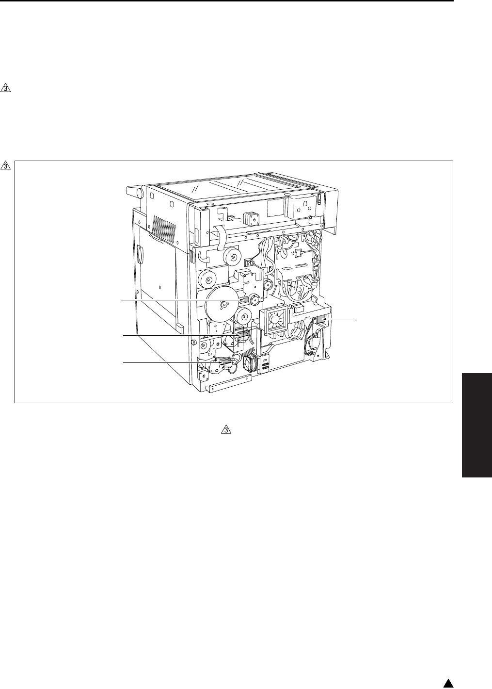
PARTS LAYOUT DRAWING
4-1
IV DIAGRAMS
3
IV DIAGRAMS
1. PARTS LAYOUT DRAWING
1.1 Main Body Parts Layout Drawing
A. Switches and sensors
(1) Main body rear side
[1] TLD (Toner level sensor) [3] PS12 (Tray set sensor/L)
[2] PS9 (Tray set sensor/U) [4] SW1 (Main power switch)
7322fs4011
[1]
[2]
[4]
[3]
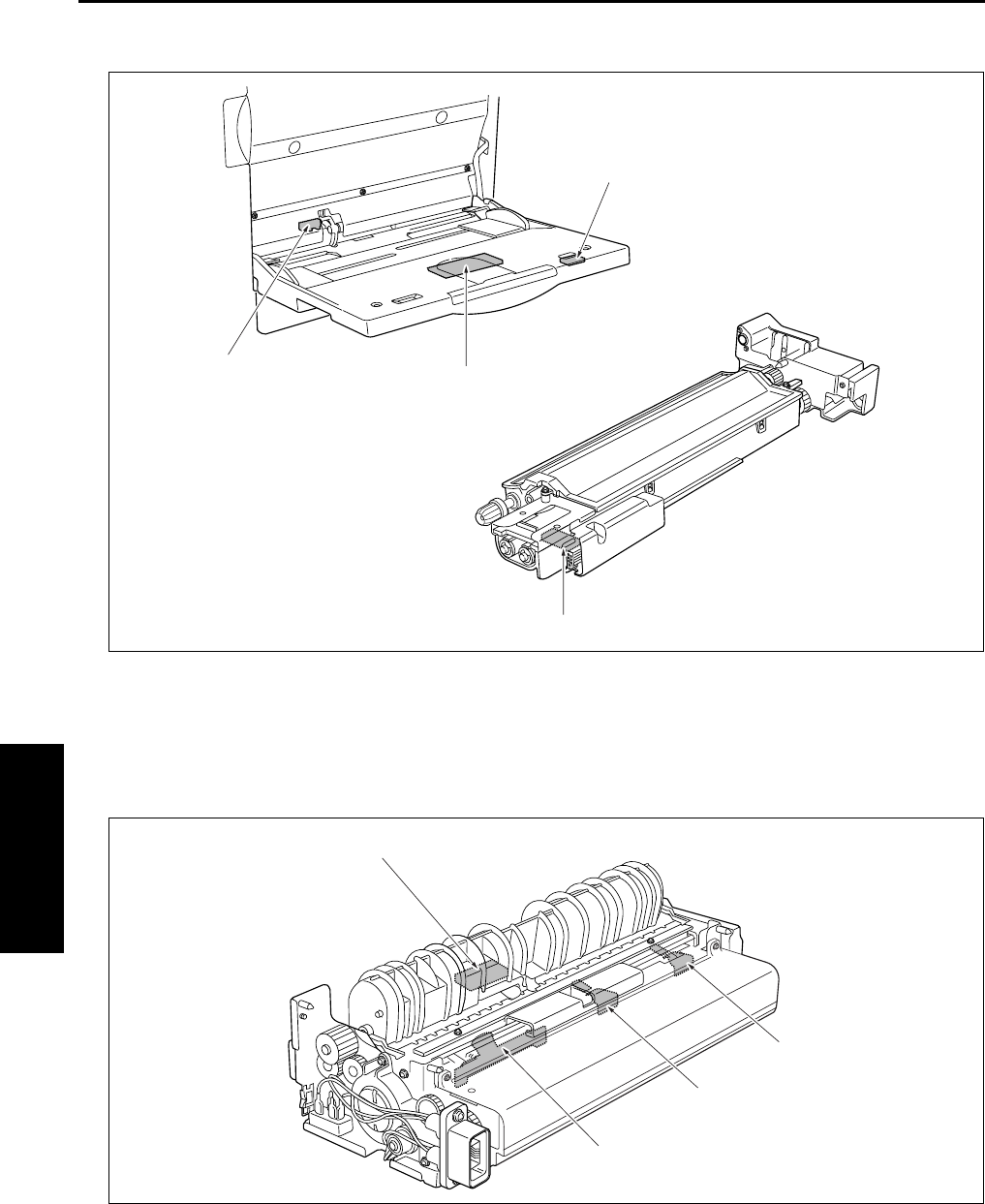
PARTS LAYOUT DRAWING
4-2
IV DIAGRAMS
(2) Bypass tray/Developing unit
(3) Fixing unit
[1] TDS (Toner density sensor) [3] PS13 (Bypass tray no paper sensor)
[2] VR1 (Bypass tray paper size sensor VR) [4] PS20 (Bypass tray paper size sensor)
[1] TH2 (Fxing temperature sensor/2) [3] TS (Thermostat)
[2] TH1 (Fxing temperature sensor/1) [4] PS2 (Fixing exit sensor)
[1]
[4]
[2]
[3]
[1]
[2]
[3]
[4]
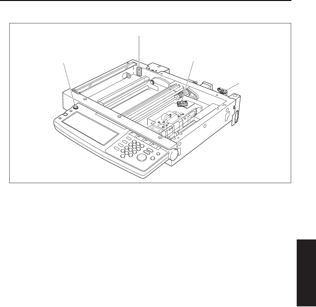
PARTS LAYOUT DRAWING
4-3
IV DIAGRAMS
(4) Scanner section/Operation section
[1] SW2 (Sub power switch) [3] PS17 (APS sensor)
[2] PS14 (Scanner home position sensor) [4] PS15 (APS timing sensor)
[2]
[3]
[1]
[4]
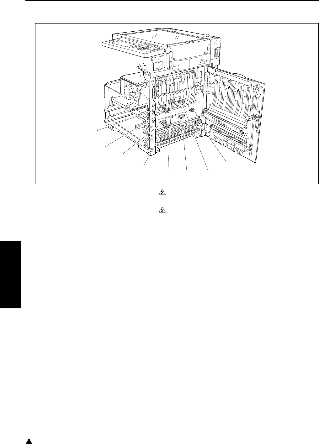
PARTS LAYOUT DRAWING
4-4
IV DIAGRAMS
3
(5) Main body right side (Paper feed section/ADU)
[1] PS4 (ADU sensor) [5] PS22 (Timing sensor/L) (7145/7235/7228 only)
[2] PS8 (No paper sensor/U) [6] PS10 (Upper limit sensor/L)
[3] PS11 (No paper sensor/L) [7] PS21 (Timing sensor/U) (7145/7235/7228 only)
[4] PS1 (Registration sensor) [8] PS7 (Upper limit sensor/U)
[1]
[2]
[3]
[4]
[5]
[6]
[7]
[8]
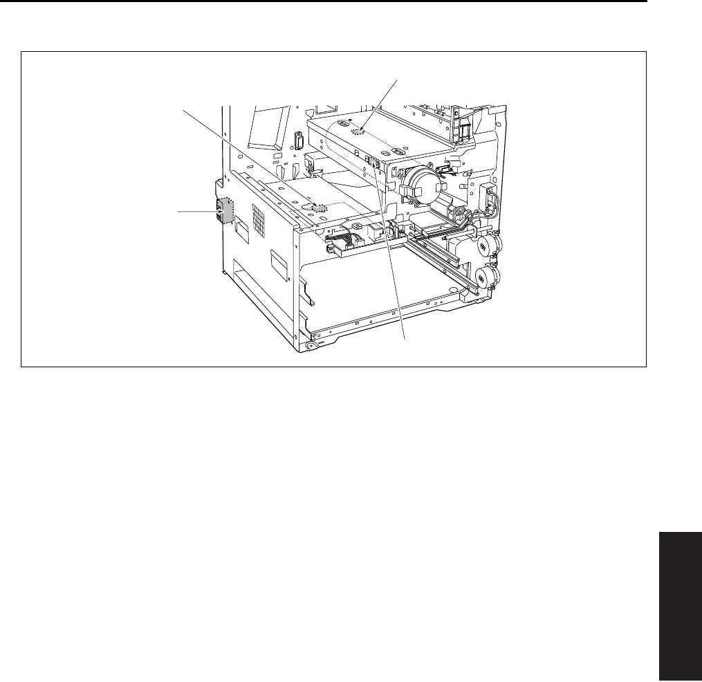
PARTS LAYOUT DRAWING
4-5
IV DIAGRAMS
(6) Main body front side/Main body left side
[1] SW3 (Interlock switch) [3] HUM1 (Humidity sensor)
[2] SW1 (Main power switch) [4] PS5 (Toner bottle sensor)
[1]
[2]
[3]
[4]
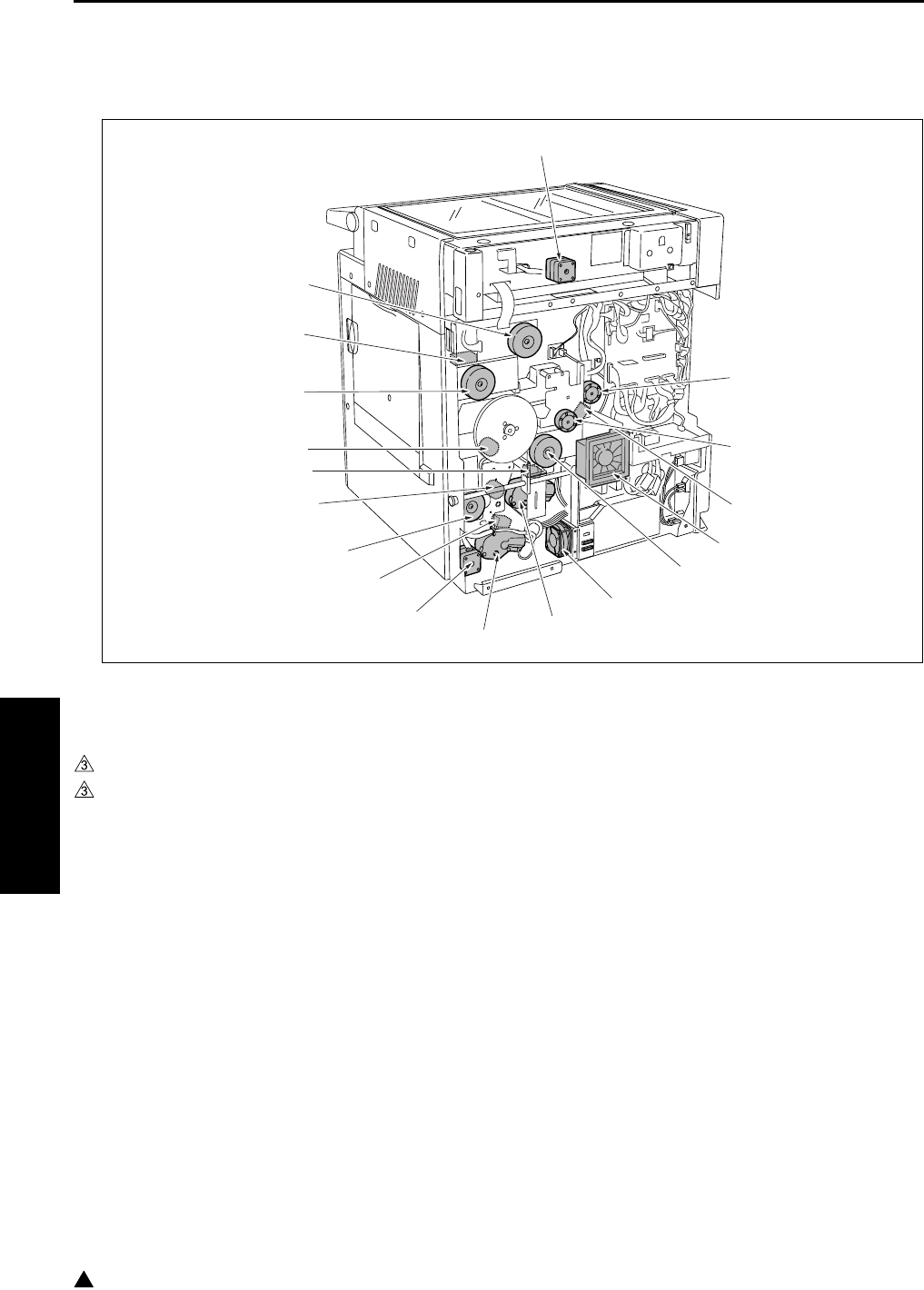
PARTS LAYOUT DRAWING
4-6
IV DIAGRAMS
3
B. Loads
(1) Main body rear side
[1] M4 (Toner supply motor 1) [10] SD2 (1st paper feed solenoid/L)
[2] M10 (Toner supply motor 2) [11] M9 (Paper feed motor)
[3] SD9 (Toner solenoid) [12] MC2 (Loop clutch)
[4] FM7 (Internal cooling fan/2) (7145 only) [13] SD1 (1st paper feed solenoid/U)
[5] M3 (Developing motor) (7145 only) [14] MC1 (Registration clutch)
[6] FM1 (DC power supply cooling fan) [15] M1 (Main motor)
[7] M7 (Tray motor/U) [16] SD5 (ADU gate solenoid)
[8] M8 (Tray motor/L) [17] M11 (Fixing motor)
[9] M6 (ADU motor) [18] M2 (Scanner motor)
[1]
[2]
[3]
[4]
[5]
[6]
[7]
[8]
[9]
[10]
[11]
[12]
[13]
[14]
[15]
[16]
[17]
[18]

PARTS LAYOUT DRAWING
4-7
IV DIAGRAMS
(2) Main body right side (Paper feed section/ADU)
(3) Write unit
[1] FM3 (Internal dehumidifying fan/1) [4] TSL (Transfer synchronization lamp)
[2] SD4 (Cleaning web solenoid) [5] FM6 (Internal dehumidifying fan/2)
[3] SD3 (Bypass feed solenoid)
[1] M5 (Polygon motor)
[1]
[5]
[2]
[3]
[4]
[1]
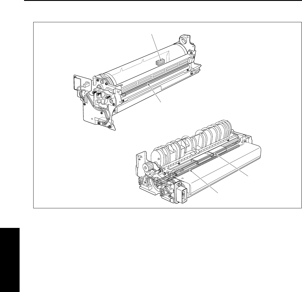
PARTS LAYOUT DRAWING
4-8
IV DIAGRAMS
(4) Drum unit/Fixing unit
[1] L2 (Fixing heater lamp/1) [3] PCL (Pre-charging exposure lamp)
[2] L3 (Fixing heater lamp/2) [4] SD7 (Separation claw solenoid)
[1]
[2]
[3]
[4]
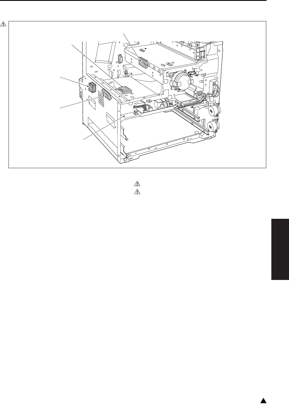
PARTS LAYOUT DRAWING
4-9
IV DIAGRAMS
3
(5) Operation section/Scanner section
[1] PTC (Heater) : Option of the service parts
setting
[3]
[4]
FM5 (Developing suction fan)
FM7 (Polygon cooling fan) (7235 only)
[2] FM4 (Internal cooling fan/1) [5] FM2 (Fixing cooling fan) (7145/7235 only)
7322fs4001
[1]
[2]
[3]
[4]
[5]
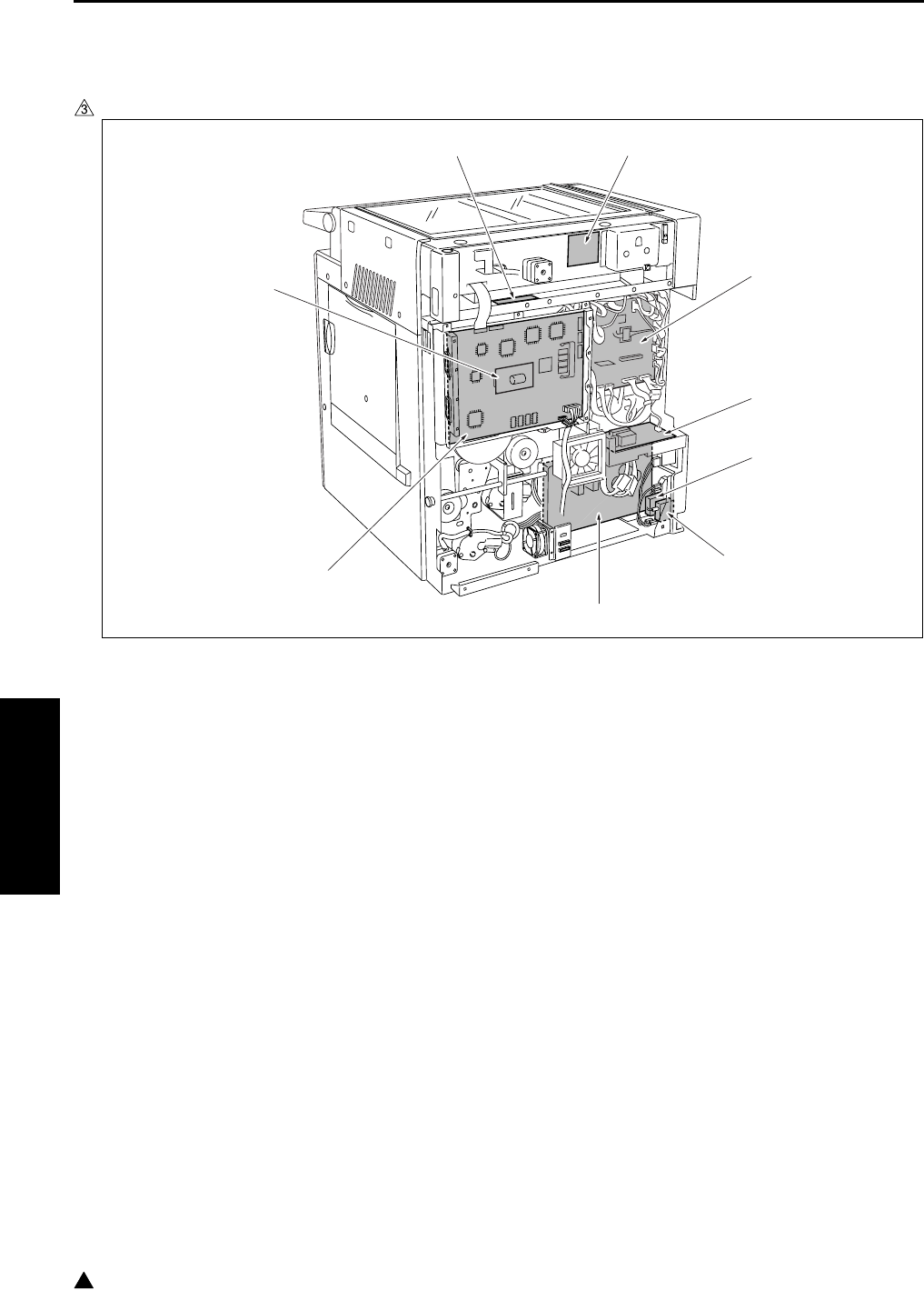
PARTS LAYOUT DRAWING
4-10
IV DIAGRAMS
3
C. PCBs and others
(1) Main body rear side
In the case of the 7145
[1] CB (Main body control board) [6] SCB (System control board)
[2] FCB (Fixing control board) : only 220V system [7] PRMB (Parameter memory board)
[3] CBR2 (Circuit breaker/2) [8] INV1 (Exposure lamp inverter)
[4] CBR1 (Circuit breaker/1) [9] SCDB (Scanner drive board)
[5] DCPS (DC power supply)
[1]
[2]
[3]
[4]
[5]
[6]
[7]
[8] [9]
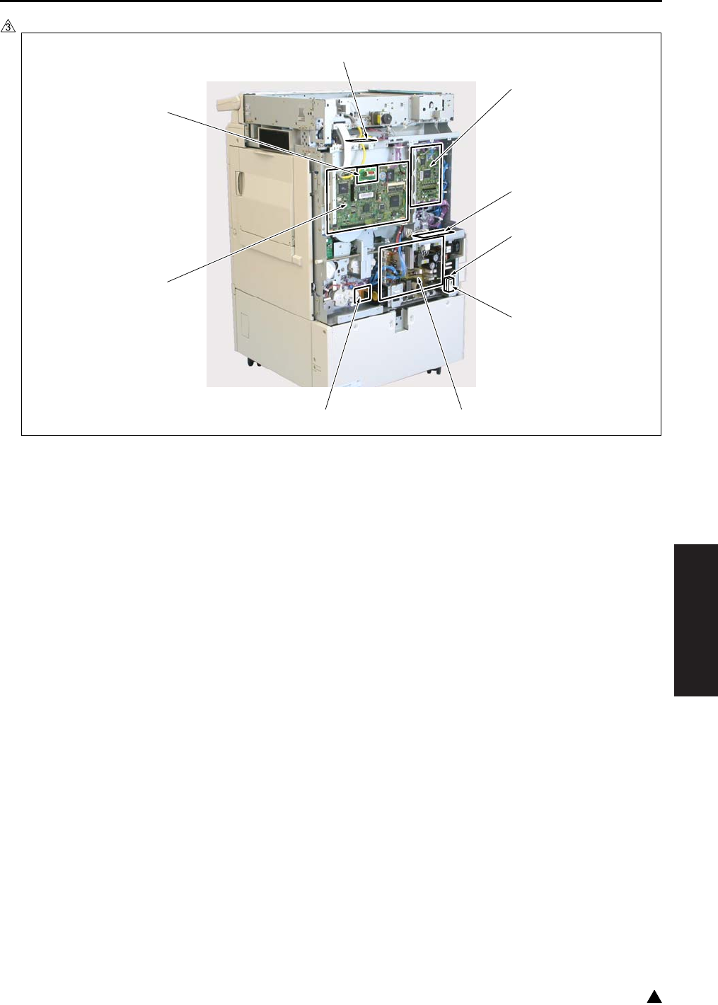
PARTS LAYOUT DRAWING
4-11
IV DIAGRAMS
3
In the case of the 7235/7228/7222
[1] CB (Main body control board) [6] ADUDB (ADU drive board)
[2] FCB (Fixing control board) [7] SCB (System control board)
[3] CBR1 (Circuit breaker/1) [8] PRMB (Parameter memory board)
[4] CBR2 (Circuit breaker/2) [9] INV1 (Exposure lamp inverter)
[5] DCPS (DC power supply)
7322fs4002e
[1]
[2]
[5][6]
[9]
[8]
[7]
[3]
[4]
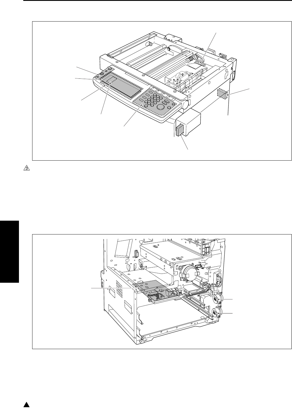
PARTS LAYOUT DRAWING
4-12
IV DIAGRAMS
3
(2) Operation section/Scanner section
(3) Main body front side
[1] TC (Total counter)
(7145 is provided as standard equipment)
[5]
[6]
LCDB (Display board)
PAKB (Panel key board)
[2] KC (Key counter) [7] PSW2B (Power SW2 board)
[3] OB (Operation board) [8] L1INVB (Exposure lamp power supply board)
[4] INV2 (Display inverter)
[1] PFDB/U (Paper feed detection board/U) [3] HV (High voltage power)
[2] PFDB/L (Paper feed detection board/L)
[1]
[2]
[3]
[4]
[5]
[6]
[7]
[8]
[3]
[1]
[2]
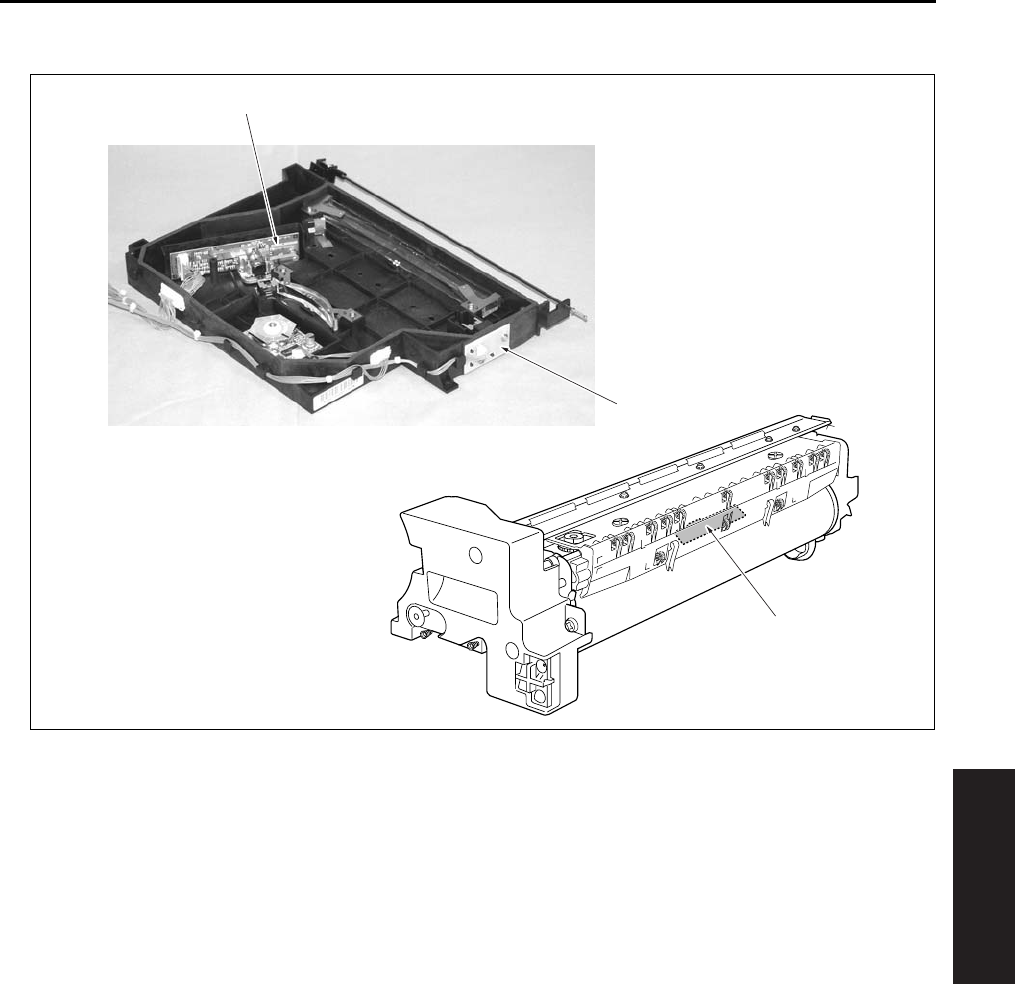
PARTS LAYOUT DRAWING
4-13
IV DIAGRAMS
(4) Write unit/Drum unit
[1] TCSB (Toner control sensor board) [3] LDB (LD drive board)
[2] INDEX (Index sensor board)
[3]
[2]
[1]
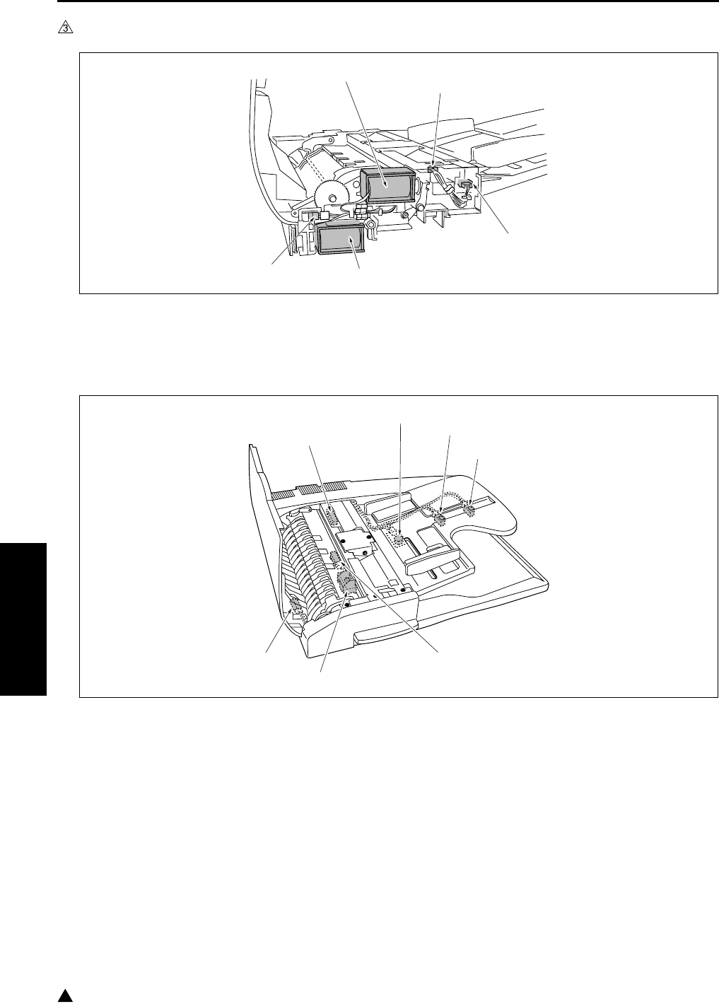
PARTS LAYOUT DRAWING
4-14
IV DIAGRAMS
3
1.2 DF-318/320 Parts Layout Drawing
[1] PS301 (Original no paper sensor) [4] SD302 (Roller pressure solenoid)
[2] SD301 (Paper exit solenoid) [5] PS304 (Cover open/close sensor)
[3] PS303 (DF open/close sensor)
[1] PS308 (Original registration sensor) [5] VR301 (Original size VR)
[2] SD303 (Stamp solenoid) [6] PS305 (Original size sensor/1)
[3] PS309 (Original conveyance sensor) [7] PS306 (Original size sensor/2)
[4] PS302 (Original exit sensor)
[1]
[2]
[3]
[4]
[5]
[1]
[3]
[2]
[4]
[5]
[6]
[7]
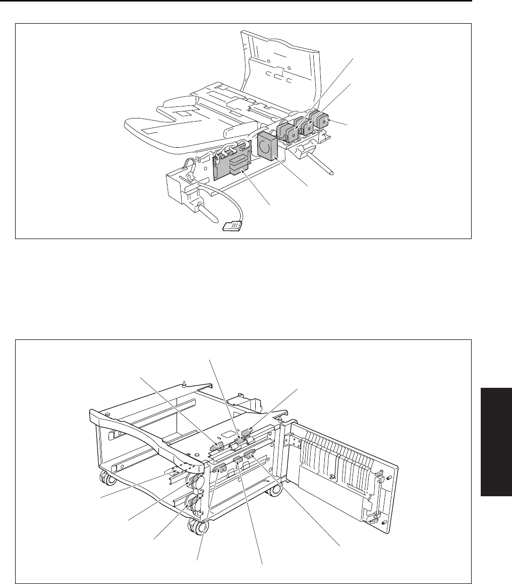
PARTS LAYOUT DRAWING
4-15
IV DIAGRAMS
1.3 DB-211 Parts Layout Drawing
[1] M301 (Original feed motor) [4] FM301 (Cooling fan)
[2] M303 (Original reverse motor) [5] DFDB (DF drive board)
[3] M302 (Original conveyance motor)
[1] PS103 (No paper senso /3) [6] PSDTB/3 (Paper size detection board/3)
[2]
[3]
PS108 (No paper sensor/4)
PS105 (Paper feed sensor/L)
[7] HTR100 (Heater) : Option of the service
parts setting
[4] PS107 (Tray upper limit sensor/4) [8] PS102 (Tray upper limit sensor/3)
[5] PSDTB/4 (Paper size detection board/4) [9] PS104 (Paper feed sensor/U)
[1]
[2]
[3]
[4]
[5]
[2]
[3]
[4]
[5]
[6]
[7]
[8]
[9]
[1]
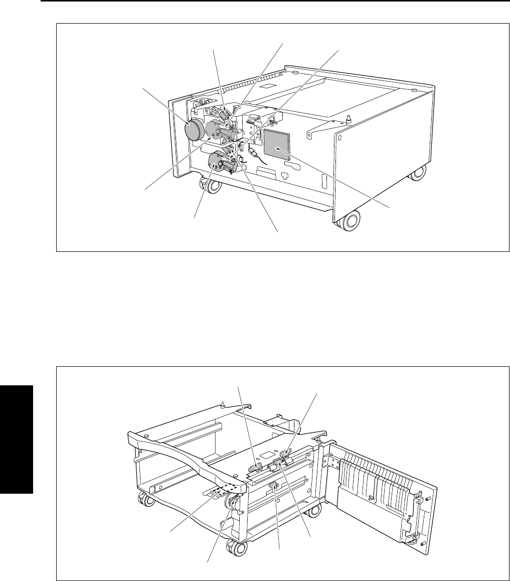
PARTS LAYOUT DRAWING
4-16
IV DIAGRAMS
1.4 DB-411 Parts Layout Drawing
[1] PS106 (Tray sensor/4) [5] M101 (Tray up drive motor/3)
[2] DBDB (DB drive board) [6] M100 (DB feed motor)
[3] SD102 (Paper feed solenoid/L) [7] SD101 (Paper feed solenoid/U)
[4] M102 (Tray up drive motor/4) [8] PS101 (Tray sensor/3)
[1] PS103 (No paper sensor/3) [4] PSDTB/3 (Paper size detection board/3)
[2]
[3]
PS104 (Paper feed sensor/U)
PS105 (Paper feed sensor/L)
[5] HTR100 (Heater) : Option of the service
parts setting
[6] PS102 (Tray upper limit sensor/3)
[2]
[3]
[4]
[5]
[6]
[7] [8] [1]
[2]
[3]
[4]
[5]
[6] [1]
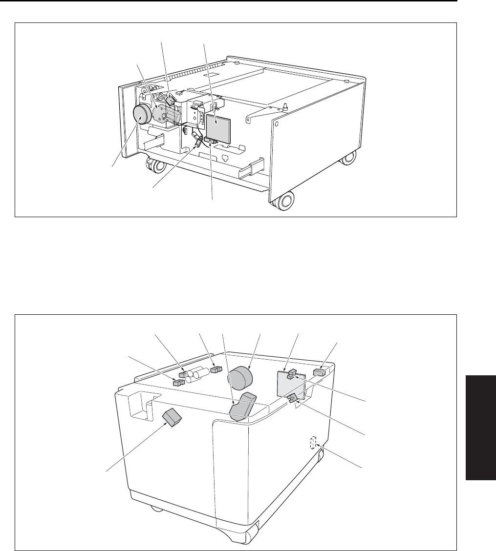
PARTS LAYOUT DRAWING
4-17
IV DIAGRAMS
1.5 LT-203 Parts Layout Drawing
[1] PS109 (Remaining paper sensor) [4] M101 (Tray up drive motor/3)
[2] PS101 (Tray sensor/3) [5] SD101 (Paper feed solenoid/U)
[3] M100 (DB feed motor) [6] DBDB (DB drive board)
[1] LTDB (LT drive board) [6] SD151 (LT paper feed solenoid)
[2] SW151 (Interlock switch) [7] PS153 (No paper sensor)
[3] PS154 (Remaining paper sensor/1) [8] PS155 (Paper feed sensor)
[4] PS151 (Remaining paper sensor/2) [9] PS152 (Tray upper limit sensor)
[5] HTR150 (Heater) : Option of the service
parts setting
[10]
[11]
M151 (Tray up drive motor)
M150 (LT paper feed motor)
[1]
[2]
[3]
[4]
[5] [6]
[1]
[2]
[3]
[4]
[5]
[6]
[7]
[8] [9] [10] [11]
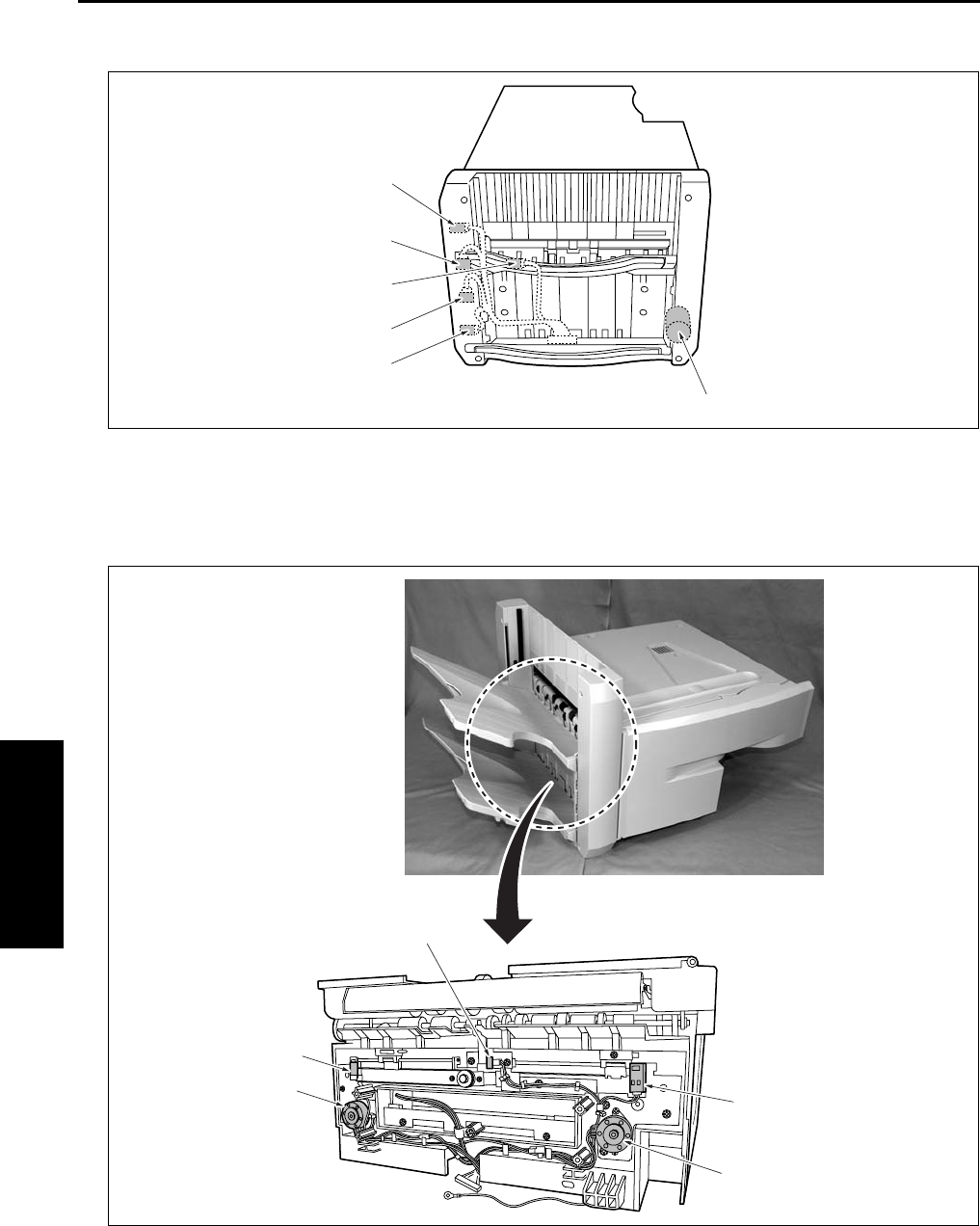
PARTS LAYOUT DRAWING
4-18
IV DIAGRAMS
1.6 FS-112 Parts Layout Drawing
[1] M706 (Tray up/down motor) [4] PS703 (Paper exit sensor)
[2] PS706 (Tray lower limit sensor) [5] PS704 (Paper exit full sensor)
[3] PS716 (Tray count sensor) [6] PS711 (Tray upper limit sensor)
[1] PS710 (Alignment HP sensor /F) [4] PS709 (Alignment HP sensor /R)
[2] M704 (Alignment motor /F) [5] PS707 (No paper sensor)
[3] M703 (Alignment motor /R)
[1]
[2]
[3]
[4]
[5]
[6]
[1]
[2]
[3]
[4]
[5]
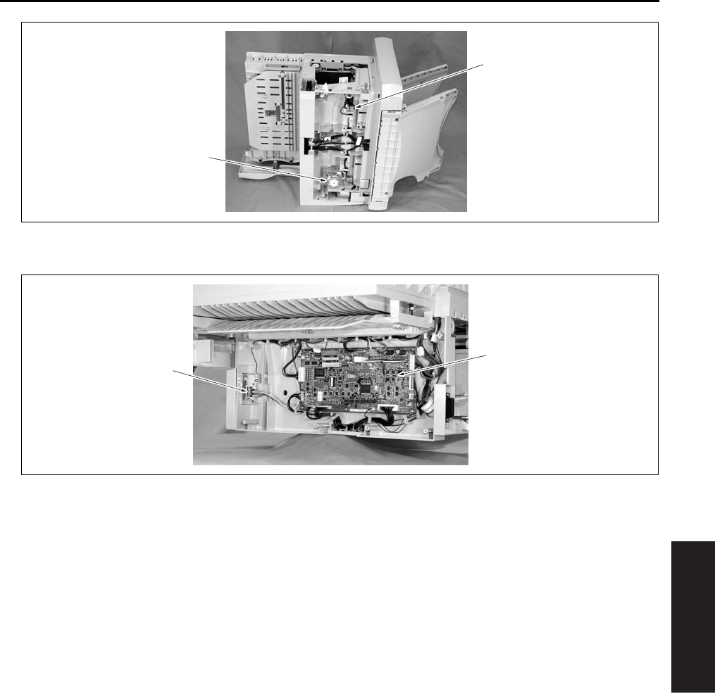
PARTS LAYOUT DRAWING
4-19
IV DIAGRAMS
[1] PS708 (Stapler unit HP sensor) [2] M705 (Stapler movement motor)
[1] MS701 (Front door switch) [2] FNSCS (FNS control board)
[1]
[2]
[2]
[1]
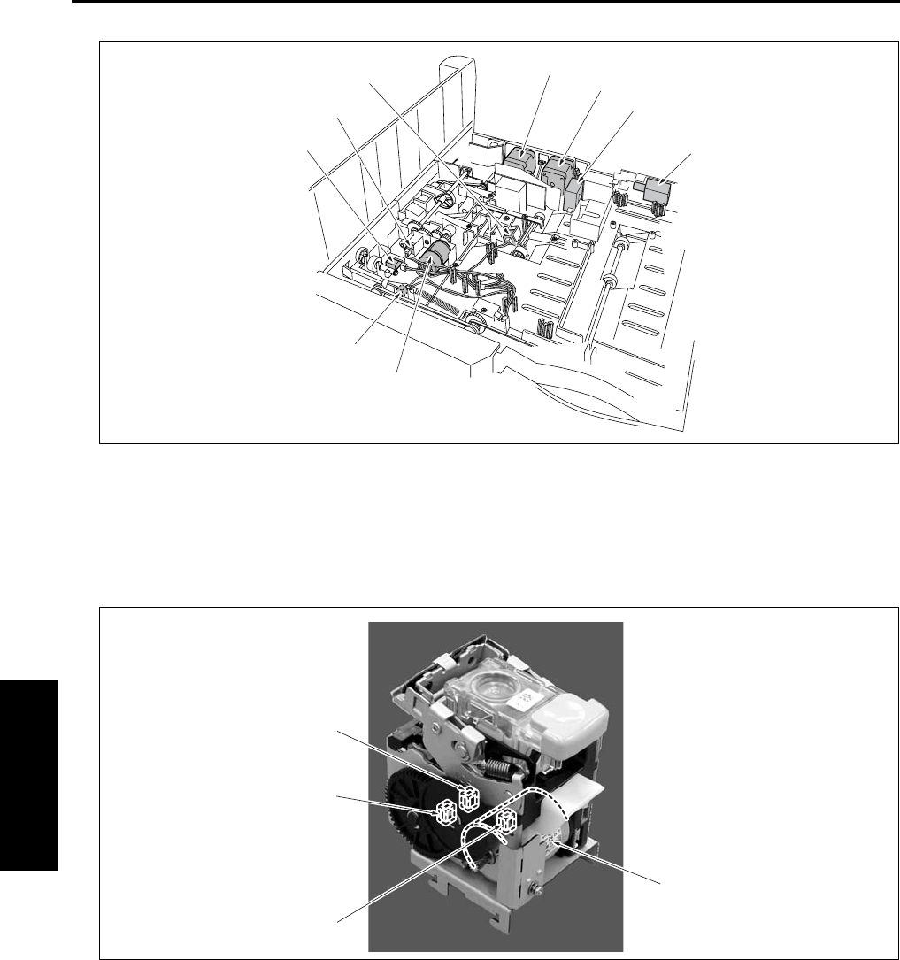
PARTS LAYOUT DRAWING
4-20
IV DIAGRAMS
[1] M707 (Paper pressure motor) [6] M702 (Paper exit motor)
[2] MS702 (Shutter switch) [7] M701 (FNS conveyance motor)
[3] PS705 (Shutter sensor) [8] FM701 (Cooling fan)
[4] PS701 (Paper pressure sensor) [9] SD701 (Roller release solenoid)
[5] PS702 (FNS entrance sensor)
[1] M708 (Stapler motor) [3] PS712 (Stapler HP sensor)
[2] PS713 (Staple detection sensor ) [4] PS714 (Stapler ready sensor)
[9]
[1]
[2]
[3]
[4]
[5] [6]
[7]
[8]
[1]
[2]
[3]
[4]
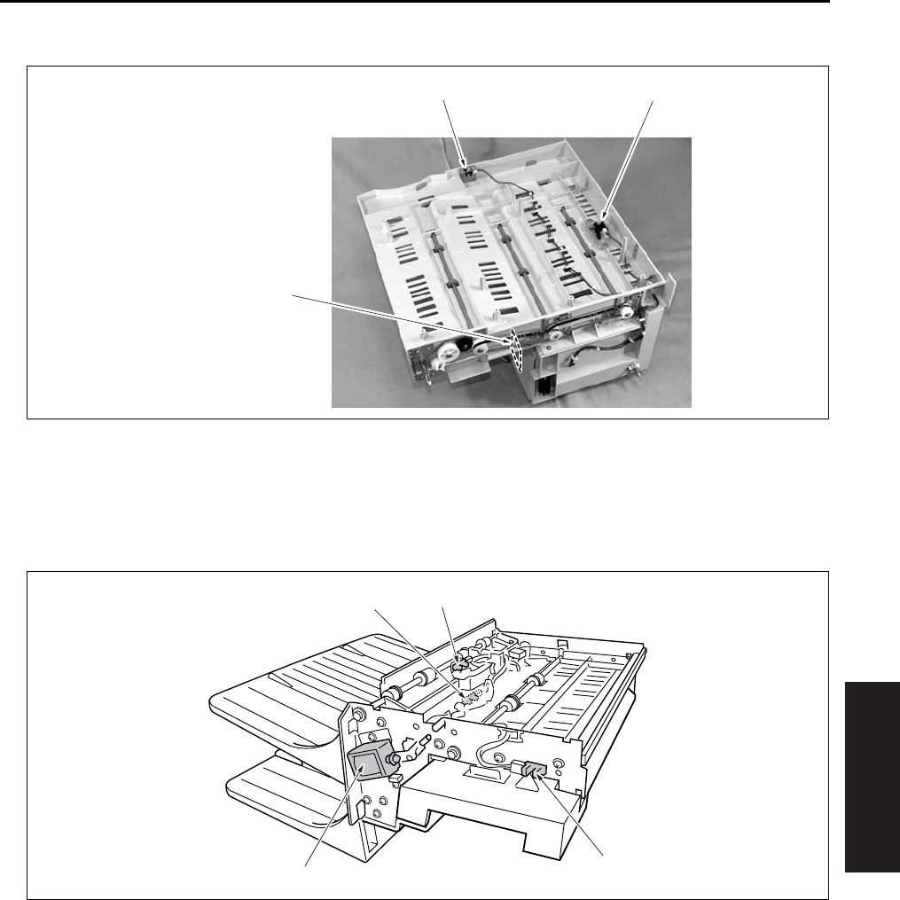
PARTS LAYOUT DRAWING
4-21
IV DIAGRAMS
1.7 RU-101 Parts Layout Drawing
1.8 IT-101 Parts Layout Drawing
[1] PS1 (Front door sensor) [3] FUB (Fuse board)
[2] PS2 (Paper exit sensor)
[1] PS25 (IT door sensor) [3] PS24 (IT paper exit sensor /L)
[2] SD8 (Gate solenoid) [4] PS23 (IT paper exit sensor /U)
[2][1]
[3]
[1]
[2]
[3] [4]

CONNECTOR LAYOUT DRAWING
4-22
IV DIAGRAMS
3
2. CONNECTOR LAYOUT DRAWING
2.1 Main Body Connector Layout Drawing
A. Main body control board
In the case of the 7145
29 (W: 32 pin)
38 (W: 9 pin)
35 (W: 5 pin)
27 (W: 8 pin)
20 (W: 4 pin)
21 (W: 6 pin)
22 (W: 5 pin)
40 (W: 4 pin)
15 (W: 24 pin)39 (W: 4 pin)
25 (W: 36 pin)26 (W: 34 pin)
19 (W: 9 pin)
2 (BK: 68 pin)
24 (W: 40 pin)
42 (W: 8 pin)
1 (W: 8 pin)
18 (W: 14 pin)
16 (W: 15 pin)
28 (W: 22 pin)
23 (GY: 22 pin)
37 (W: 8 pin)
36 (W: 10 pin)
41 (W: 11 pin)
17 (W: 36 pin)
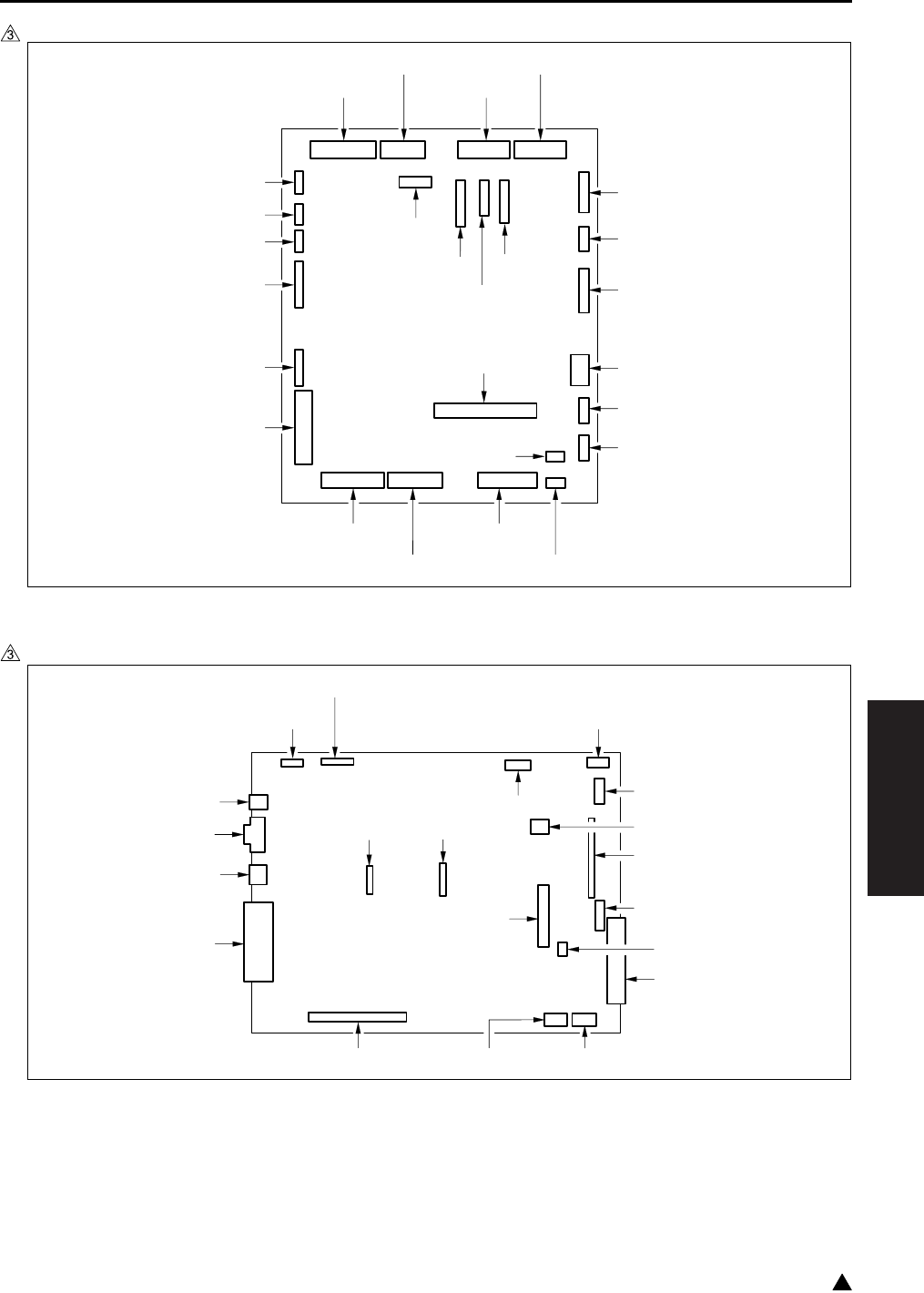
CONNECTOR LAYOUT DRAWING
4-23
IV DIAGRAMS
3
In the case of the 7235/7228/7222
B. System control board
In the case of the 7145
7322fs4003
29 (W: 30 pin)
38 (W: 9 pin)
35 (W: 5 pin)
27 (W: 8 pin)
20 (W: 4 pin)
21 (W: 6 pin)
22 (W: 5 pin)
14 (W: 4 pin)15 (W: 30 pin)
25 (W: 34 pin)26 (W: 36 pin)
15 (W: 30 pin)
24 (W: 38 pin)
90 (W: 8 pin)
42 (W: 8 pin)
18 (W: 14 pin)
33 (W: 4 pin)
32 (W: 3 pin)
19 (W: 3 pin)
28 (W: 22 pin)
23 (GY: 22 pin)
37 (W: 8 pin)
36 (W: 10 pin)
31 (W: 11 pin)
16 (W: 9 pin)
17 (W: 36 pin)
7145fs4033
34 (W: 24 pin) 431 (W: 5 pin)
500 (W: 4 pin)
33 (BK: 24 pin)32 (BK: 20 pin)
44 (W: 22 pin)
31 (W: 7 pin)37 (BK: 120 pin)
432 (W: 24 pin)
35 (W: 144 pin)
47 (W: 2 pin)
42 (W: 9 pin)
38 (BK: 100 pin)
502 (W: 3 pin)
40 (W: 36 pin)
41 (W: 8 pin)
39 (W: 9 pin)
45 (W: 4 pin)
501 (BK: 44 pin)
46 (W: 50 pin)
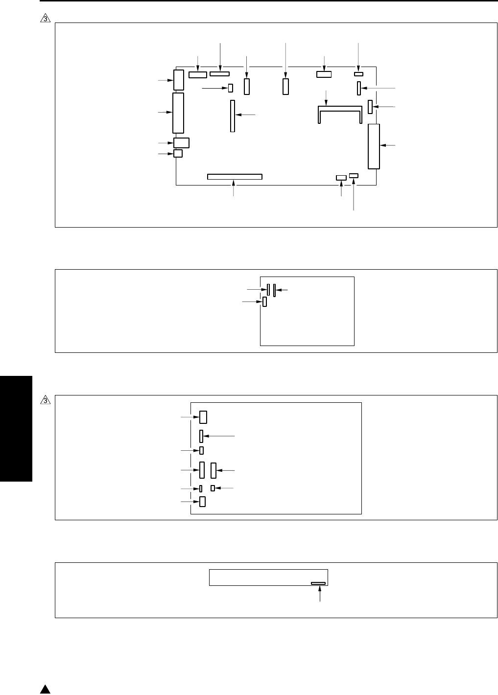
CONNECTOR LAYOUT DRAWING
4-24
IV DIAGRAMS
3
In the case of the 7235/7228/7222
C. High voltage power
D. DC power supply
E. A/D conversion board
7322fs4004
52 (W: 28 pin)
431 (W: 5 pin)
500 (W: 4 pin)
58 (W: 20 pin)
59 (GY: 24 pin)
502
(W: 3 pin)
44 (W: 22 pin)
53 (W: 144 pin)
43 (W: 6 pin)
432 (W: 12 pin)
56 (BK: 100 pin)
42 (W: 9 pin)
48 (W: 4 pin)
41 (W: 8 pin)
40 (W: 36 pin)
57 (W: 9 pin)
501 (BK: 44 pin)
55 (BK: 120 pin)
46 (W: 50 pin)
70 (W: 9 pin)
72 (W: 3 pin)
71 (W: 12 pin)
7322fs4005e
1 (W: 5 pin)
2 (W: 7 pin) (7145)
2 (W: 6 pin) (7235/7228/7222)
3 (W: 5 pin)
7 (W: 26 pin)
8 (W: 4 pin)
5 (W: 4 pin)
6 (W: 20 pin)
10 (W: 3 pin)
60 (W: 50 pin)

CONNECTOR LAYOUT DRAWING
4-25
IV DIAGRAMS
3
F. Scanner drive board (7145 only)
G. Operation board
H. LD drive board
I. Index sensor board
J. Toner control sensor board
64 (W: 9 pin)
61 (W: 15 pin)
60 (W: 5 pin)
63 (W: 4 pin)62 (W: 3 pin)
7322fs4006e
80 (W: 24 pin) (7145)
80 (W: 28 pin) (7235/7228/7222)
89 (W: 8 pin)
84 (W: 13 pin)
83 (W: 4 pin)
86 (W: 14 pin)
7322fs4007e
50 (W: 24 pin) (7145)
50 (W: 12 pin) (7235/7228/7222)
51 (W: 5 pin)
1 (W: 7 pin)
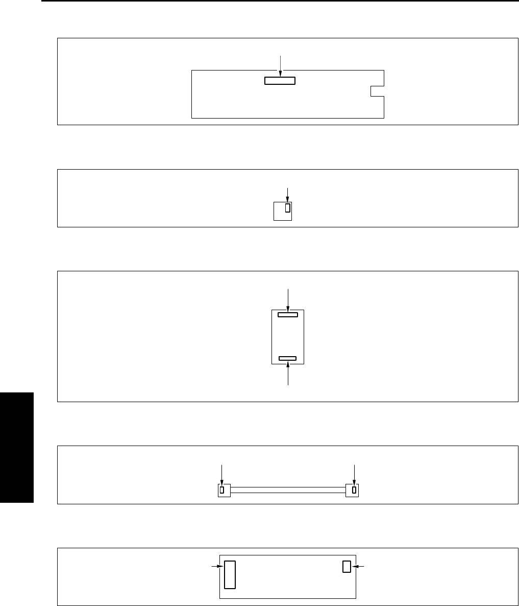
CONNECTOR LAYOUT DRAWING
4-26
IV DIAGRAMS
K. Power SW2 board
L. Paper size detection board /U, /L
M. Parameter memory board
N. Exposure lamp power supply board
O. Display inverter
1 (W: 8 pin)
1 (W: 5 pin)
2 (BK: 24 pin)
1 (BK: 20 pin)
97 (W: 2 pin) 96 (W: 2 pin)
77 (W: 4 pin) 71 (W: 3 pin)

CONNECTOR LAYOUT DRAWING
4-27
IV DIAGRAMS
3
P. Exposure lamp inverter
Q. ADU drive board (Except the 7145)
R. Fixing control board (Metric size only)
931 (W: 4 pin) 930 (W: 3 pin)
7322fs4008
70 (W: 9 pin)71 (W: 6 pin)
99 (W: 4 pin)
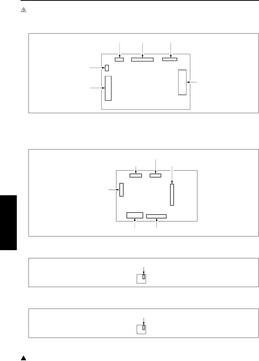
CONNECTOR LAYOUT DRAWING
4-28
IV DIAGRAMS
3
2.2 DF-318/320 Connector Layout Drawing
A. DF drive board
2.3 DB-211 Connector Layout Drawing
A. DB drive board
B. Paper size detection board /3
C. Paper size detection board /4
214 (W: 28 pin)
212 (W: 7 pin)215 (W: 18 pin)216 (W: 6 pin)
213 (W: 3 pin)
211 (W: 36 pin)
100 (6 pin)
102 (11 pin)
103 (24 pin) 104 (18 pin)
101 (9 pin)
106 (19 pin)
1 (5 pin)
1 (5 pin)
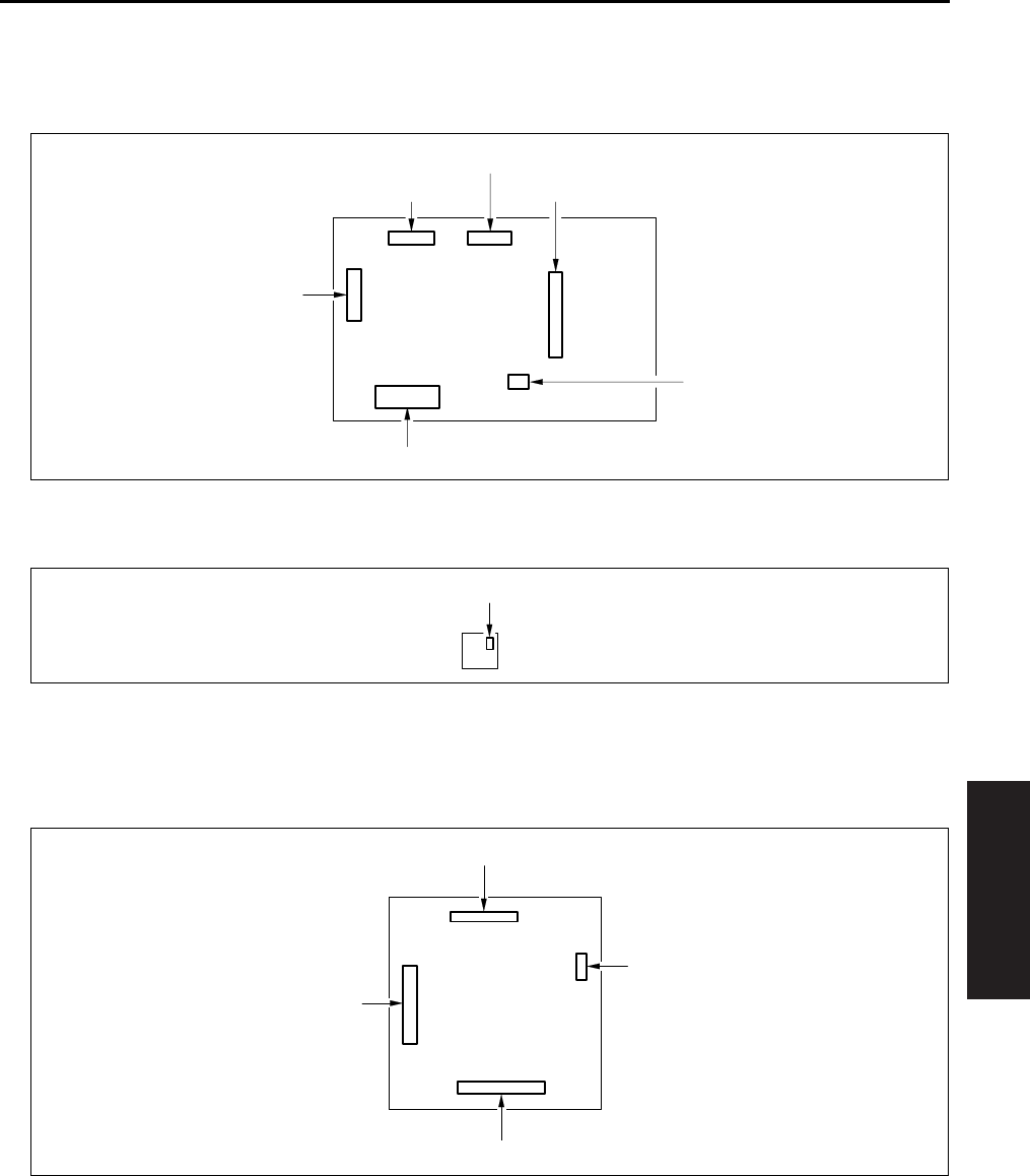
CONNECTOR LAYOUT DRAWING
4-29
IV DIAGRAMS
2.4 DB-411 Connector Layout Drawing
A. DB drive board
B. Paper size detection board /3
2.5 LT-203 Connector Layout Drawing
A. LT drive board
100 (6 pin)
102 (11 pin)
103 (24 pin)
105 (3 pin)
101 (9 pin)
106 (19 pin)
1 (5 pin)
112 (11 pin)
110 (19 pin)
114 (3 pin)
113 (17 pin)
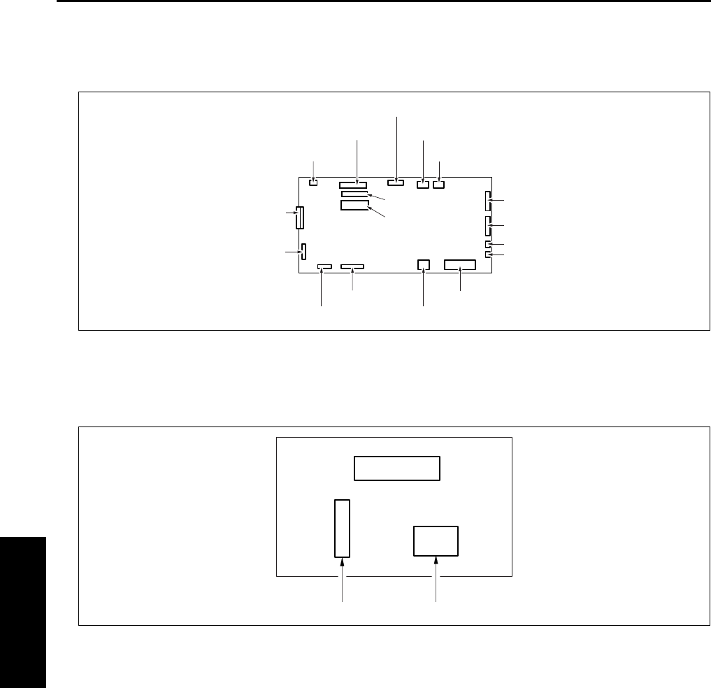
CONNECTOR LAYOUT DRAWING
4-30
IV DIAGRAMS
2.6 FS-112 Connector Layout Drawing
A. FNS control board
2.7 RU-101 Connector Layout Drawing
A. Fuse board
704 (12 pin)
702 (11 pin)
713 (3 pin)
710 (2 pin)
708 (8 pin)
709 (12 pin)
707 (30 pin)
705 (W: 6 pin) 717 (2 pin)
703 (12 pin)
706 (2 pin)
714 (15 pin)
716 (36 pin)
FNS CB
715 (30 pin)
701 (10 pin)
712(2 pin)
711 (2 pin)
3 (W: 6 pin) 4 (W: 2 pin)
F1

JAM CODE LIST
4-31
IV DIAGRAMS
3
3. JAM CODE LIST
Classification
Jam
Code
Causes Resulting
operation
Correction
Bypass
J10
During operation
PS1 (Registration sensor) failed to turn ON
within a predetermined time after SD3
(Bypass solenoid) ON.
If copying is in
progress at
time of jam, the
copier com-
pletes ejection
and then stops.
Take out the paper
from the bypass
tray, and remove
any jammed paper.
Upper
tray
J11 PS1 (Registration sensor) failed to turn ON
within a predetermined time after SD1 (First
paper feed solenoid/U) ON.
Open the ADU door,
remove any jammed
paper. Pull out the
tray, and remove
any jammed paper.
Lower
tray
J12 PS1 (Registration sensor) failed to turn ON
within a predetermined time after SD2 (First
paper feed solenoid/L) ON.
DB tray
J13 PS104 (First paper feed sensor/U) failed to
turn ON within a predetermined time after
SD101 (Paper feed solenoid/U) ON.
Open the DB con-
veyance door,
remove any jammed
paperr. Pull out the
tray, and remove
any jammed paper.
J14 PS105 (First paper feed sensor/L) failed to
turn ON within a predetermined time after
SD102 (Paper feed solenoid/L) ON.
LT-203 J15 PS155 (Paper feed sensor) failed to turn ON
within a predetermined time after SD151 (LT
paper feed solenoid) ON.
Open the LT top
cover, remove any
jammed paper.
DB tray
J16-1 The PS1 (Registration sensor) is not turned
ON in the specified period of time after either
of the PS104 (Paper feed sensor/U), the
PS105 (Paper feed sensor/L) and the PS155
(Paper feed sensor) is turned ON and then
turned OFF.
Open the ADU door,
remove any jammed
paper.
LT-203 J16-2 PS104 (Paper feed sensor/U) or PS105
(Paper feed sensor/L) failed to turn ON
within a predetermined time after SD151 (LT
paper feed solenoid) ON.
Open the LT top
cover, remove any
jammed paper.
Others J20-2 ADU door open jam
SW3 (Interlock switch) went OFF during
copying/printing.
Printer section
stops immedi-
ately.
Remove jammed
paper according to
message.
Others
FS-112
J20-3 FNS front door open jam
MS701 (Front door) went OFF during copy-
ing/printing or, came off from the main body.
Others
FS-113
J20-3 FNS upper front cover open jam
PC17 (Front door detection sensor) went
OFF during copying/printing or, came off
from the main body.
Others
FS-114
J20-3 FNS front door open jam
The S1-FN (Front cover open/close detec-
tion SW) turned OFF while in copying/print-
ing.

JAM CODE LIST
4-32
IV DIAGRAMS
3
Others J20-4
During operation
When an emergency stop instruction is
received from the system while in the system
emergency stop jam print job.
Printer section
stops immedi-
ately.
Remove jammed
paper according to
message.
Others
RU-101
J20-5 RU-101 front door open jam
PS1 (Front door sensor) went OFF during
copying/printing.
Others
FS-112
J20-6 FNS shutter switch operation jam
MS702 (Shutter) went ON during copying/
printing.
Others
FS-114
J20-6 Intermediate transport guide open jam
The S4-FN (Intermediate jam guide detec-
tion SW) turned OFF while in copying/print-
ing.
Shutter open jam
The S2-FN (Shutter detection SW) turned
OFF while in copying/printing.
Others
FS-113
J20-7 Top cover open jam
PC18 (Top cover detection sensor) went
OFF during copying/printing.
Others
SK-114
J20-7 SK-114 open jam
The S4-SK (Saddle safety switch) turned
OFF while in copying/printing.
Others
FS-113
J20-8 Connecting connector coming off jam
The FS-113 connecting connector comes off
from the main body during copying/printing.
Conveyance
J30 PS1 (Registration sensor) failed to turn ON
within a predetermined time after MC1 (Reg-
istration clutch) ON.
Open the ADU door,
remove any jammed
paper.
J31 PS2 (Fixing exit sensor) failed to turn ON
within a predetermined time after MC1 (Reg-
istration clutch) ON.
Fixing/
Exit
J32 The PS2 (Fixing exit sensor) is not turned
OFF in the specified period of time (by paper
sizes) after it is turned ON.
Others J50-1 Failed to receive print request from system
within a predetermined time after PS1 (Reg-
istration sensor) ON.
The main body
stop immedi-
ately.
J50-2 “Valid” signal failed to turn ON within a pre-
determined time after start of printing.
J50-3 MC1 (Registration clutch) failed to turn ON
within a predetermined time after start of
printing.
Classification
Jam
Code
Causes Resulting
operation
Correction

JAM CODE LIST
4-33
IV DIAGRAMS
3
DF-318/
320
J61-1
During operation
The PS304 (Cover open/close sensor) is
turned OFF while in operation.
The RADF
stops immedi-
ately.
Open the open/
close cover, remove
any jammed paper.
Remove any
jammed paper from
the main body’s
conveyance sec-
tion.
J61-2 The PS303 (DF open/close sensor) is turned
OFF while in operation.
J62-1 Original did not feed.
J62-2 PS309 (Original conveyance sensor) failed
to turn ON within a predetermined time after
start of refeed for single sided original.
J62-3 PS309 (Original conveyance sensor) failed
to turn ON within a predetermined time after
start of reverse refeed for double sided origi-
nal.
J62-4 PS309 (Original conveyance sensor) did not
go OFF within the specified period after it
went ON, during original exit.
J62-5 PS309 (Original conveyance sensor) did not
go OFF within the specified period after it
went ON, during original reversal.
J63-1 PS302 (Original exit sensor) did not go ON
during original exit.
J63-2 PS302 (Original exit sensor) did not go OFF
within the specified period after it went ON,
during original exit.
J63-3 PS308 (Original registration sensor) failed to
turn OFF within a predetermined time after
start of refeed for single sided original.
J63-4 PS309 (Original conveyance sensor) failed
to turn OFF within a predetermined time after
start of reverse refeed for double sided origi-
nal.
J65-1
When idling
PS308 (Original registration sensor) ON dur-
ing idling state.
—Open the open/
close cover, remove
any jammed paper.
J65-2 PS309 (Original conveyance sensor) ON
during idling state.
Open the open/
close cover and the
reverse guide and
remove jammed
paper, if any.
J65-3 PS308 (Original registration sensor), PS309
(Original conveyance sensor) ON during
idling state.
J65-8 PS302 (Original exit sensor) ON during idling
state.
J65-9 PS308 (Original registration sensor), PS302
(Original exit sensor) ON during idling state.
J65-10
PS309 (Original conveyance sensor), PS302
(Original exit sensor) ON during idling state.
Classification
Jam
Code
Causes Resulting
operation
Correction

JAM CODE LIST
4-34
IV DIAGRAMS
3
DF-318/
320
J65-11
When idling
PS308 (Original registration sensor), PS309
(Original conveyance sensor), PS302 (Origi-
nal exit sensor) ON during idling state.
—Open the open/
close cover and the
reverse guide and
remove jammed
paper, if any.
FS-112 J72-1 PS702 (FNS entrance sensor) ON during
idling state.
Remove jammed
paper, if any, from
the FNS/main body.
FS-113
RU-101
J72-1 The PS2 (Passage sensor) of RU-101 is
turned ON while in idling.
Remove jammed
paper, if any, from
the FNS/RU/main
body.
FS-114 J72-1 PC4-FN (Entrance sensor) is ON during
idling.
Remove jammed
paper, if any, from
the FNS/main body.FS-112 J72-2 PS707 (No paper sensor) ON during idling
state.
FS-113 J72-2 While in idling, either of the PC4 (Upper path
sensor), the PC2 (Lower path sensor), PC3
(Storage sensor), PC5 (Process tray paper
exit sensor) and the PC1 (1st tray exit sen-
sor) is ON.
Remove jammed
paper, if any, from
the FNS/main body.
FS-114 J72-2 PC5-FN (Transport sensor) is ON during
idling.
J72-3 PC8-FN (Storage tray detecting sensor) is
ON during idling.
SK-114 J72-4 PC20-SK (Saddle exit sensor) is ON during
idling.
Remove jam paper
from SK/FNS if any.
FS-112
J72-16
During operation
PS702 (FNS entrance sensor) failed to turn
ON within a predetermined time after PS2
(Fixing exit sensor) ON.
The FNS/main
body stop
immediately.
Remove jammed
paper, if any, from
the FNS/main body.
FS-113
RU-101
J72-16
After the PS2 (Fixing exit sensor) is turned
ON, the PS2 (Passage sensor) of RU-101 is
not turned ON.
Remove jammed
paper, if any, from
the FNS/RU/main
body.
FS-114
J72-16
PC4-FN (Entrance sensor) does not ON
after specified time from PS2 (fixing exit sen-
sor) ON.
Open front door and
remove jammed
paper if any.
FS-112
J72-17
PS707 (No paper sensor) failed to turn ON
within a predetermined time after PS702
(FNS entrance sensor) ON. (Straight, sort/
group mode for other than small size)
Remove jammed
paper, if any, from
the FNS/the main
body.
Classification
Jam
Code
Causes Resulting
operation
Correction

JAM CODE LIST
4-35
IV DIAGRAMS
1
FS-113
J72-17
During operation
• The PS2 (Passage sensor) of RU-101 is
not turned OFF.
• After the PS2 of RU-101 is turned ON,
the PC1 (1st tray exit sensor) is not
turned ON. (Sort/Group)
• After the PS2 of RU-101 is turned ON,
the PC4 (Upper path sensor) is not
turned ON. (Staple)
• After the PS2 of RU-101 is turned ON,
the PC2 (Lower path sensor) is not
turned ON. (Staple/Sort/Group)
• The PC4 is not turned OFF after it is
turned ON. (Staple)
• The PC2 is not turned OFF after it is
turned ON. (Staple/Sort/Group)
• After the PC4 is turned ON, the PC3
(Storage sensor) is not turned ON. (Sta-
ple)
• After the PC2 is turned ON, the PC3 is
not turned OFF. (Staple/Sort/Group)
The FNS/main
body stop
immediately.
Pull out the FNS
from the main body,
and remove
jammed paper, if
any, from the FNS/
main body.
FS-114
J72-17
PC4-FN (Entrance sensor) does not OFF
after specified time from ON.
Open front door and
remove jammed
paper if any.PC5-FN (Transport sensor) does not ON
after specified time from PC4-FN (Entrance
sensor) ON.
FS-113
J72-18
• After the PC1 (1st tray exit sensor) is
turned ON, it is not turned OFF.
• After the PC3 (Storage sensor) is turned
ON, it is not turned OFF.
Pull out the FNS
from the main body,
and remove
jammed paper, if
any, from the FNS/
main body.
FS-114
J72-18
PC5-FN (Transport sensor) does not OFF
after specified time from ON.
Open front door and
remove jammed
paper if any.
FS-112
J72-19
PS702 (FNS entrance sensor) failed to turn
OFF within a predetermined time after turn-
ing ON. (Staple, sort/group)
Remove jammed
paper, if any, from
the FNS/main body.
J72-21
PS707 (No paper sensor) failed to turn OFF
within a predetermined time after PS703
(Paper exit sensor) turning ON. (Small size
staple, sort/group)
Classification
Jam
Code
Causes Resulting
operation
Correction

JAM CODE LIST
4-36
IV DIAGRAMS
3
FS-113
J72-21
During operation
While exiting paper after completion of sta-
pling, the PC5 (Process tray paper detection
sensor) is not turned OFF after it is turned
ON.
The FNS/main
body stop
immediately.
Pull out the FNS
from the main body,
and remove
jammed paper, if
any, from the FNS/
main body.
FS-114
SK-114
J72-21
After specified time from stapling, PC8-FN
(Strorage tray paper detect sensor) or
PC20-SK (Saddle exit sensor) of SK-114
does not ON.
Remove jammed
paper, if any, from
the FNS/main body.
FS-112
J72-23
PS707 (No paper sensor) failed to turn OFF
within a predetermined time after PS703
(Paper exit sensor) turning ON. (Straight)
FS-114
SK-114
J72-25
PC22-SK (Crease roller home position sen-
sor) does not ON within specified time.
Open front door and
remove jammed
paper if any.FS-114
PK-114
J72-43
M1-PK (Punch motor) does not OFF after
specified time from ON.
FS-112
J72-81
Staple jam M708 (Stapler motor) failed to
turn OFF within a predetermined time after
turning ON. (Forward operation not com-
pleted.)
Remove the
jammed staple.
FS-113
J72-81
After the staple motor 1 starts forward rota-
tion, the PC14 (Staple home sensor) is not
turned ON in the specified period of time.
Then, the staple motor 1 starts backward
rotation and the PC14 is turned ON in the
specified period of time.
The FNS/main
body stop
immediately.
Pull out the FNS
from the main body,
and remove
jammed staples, if
any.
FS-114
J72-81
Staple home position sensor does not ON
after specified time from staple motor for-
ward rotation.
Remove jammed
staple, if any.
FS-113
J72-82
After the staple motor 2 starts forward rota-
tion, the PC14 (Staple home sensor) is not
turned ON in the specified period of time.
Then, the staple motor 2 starts backward
rotation and the PC14 is turned ON in the
specified period of time.
Pull out the FNS
from the main body,
and remove
jammed staples, if
any.
J72-83
After the staple motors 1 and 2 start forward
rotation, the PC14 (Staple home sensor) is
not turned ON in the specified period of time.
Then, the staple motors 1 and 2 start back-
ward rotation and the PC14 is turned ON in
the specified period of time.
Classification
Jam
Code
Causes Resulting
operation
Correction

JAM CODE LIST
4-37
IV DIAGRAMS
1
SK-114
J72-84
During operation
Saddle staple home position sensor 1 does
not ON within specified time from saddle sta-
ple motor 1 forward rotation.
The FNS/main
body stop
immediately.
Remove jammed
staple, if any.
J72-85
Saddle staple home position sensor 2 does
not ON within specified time from saddle sta-
ple motor 2.
IT-101 J75-1
When idling
PS23 (IT exit sensor/U) or PS24 (IT exit sen-
sor /L) went ON during idling.
—Open the IT cover,
remove any jammed
paper.
J75-10
During operation
PS23 (IT exit sensor/U) failed to turn ON
within a predetermined time after PS2 (Fix-
ing exit sensor) turning ON.
Printer section
stops immedi-
ately.
J75-11
PS24 (IT exit sensor/L) failed to turn ON
within a predetermined time after PS2 (Fix-
ing exit sensor) turning ON.
J75-12
PS2 (Fixing exit) failed to turn OFF within a
predetermined time after PS23 (IT exit sen-
sor /U) or PS24 (IT exit sensor/L) turning
ON.
J75-13
The IT door open jam
PS25 (IT door sensor) went OFF during
copying/printing.
Paper
feed
J81
When idling
PS1 (Registration sensor) ON during idling
state.
—Open the ADU door,
remove any jammed
paper.
J82 PS105 (Paper feed sensor/L) ON during
idling state.
Open the DB con-
veyance door,
remove jammed
paper. If paper is
jammed in the main
body: open the ADU
door, remove the
jammed paper.
J83 PS155 (Paper feed sensor) ON during idling
state.
Open the LT top
cover, remove any
jammed paper.
Paper
exit
J90 PS2 (Fixing exit sensor) ON during idling
state.
Open the ADU door,
remove any jammed
paper.
Classification
Jam
Code
Causes Resulting
operation
Correction

JAM CODE LIST
4-38
IV DIAGRAMS
ADU
conveyance
J92
During operation
PS1 (Registration sensor) failed to turn ON
within a predetermined time after start of
ADU reversal.
Printer section
stops immedi-
ately.
Open the ADU door,
remove any jammed
paper.
J97-1 PS4 (ADU sensor) failed to turn ON within a
predetermined time after PS2 (Fixing exit
sensor) ON.
J97-2 PS4 (ADU sensor) failed to turn OFF within a
predetermined time after turning ON.
J100
When idling
PS4 (ADU sensor) ON during idling state. —
Classification
Jam
Code
Causes Resulting
operation
Correction

ERROR CODE LIST
4-39
IV DIAGRAMS
3
4. ERROR CODE LIST
4.1 Error Code List
Classification
Warning
code
Causes Resulting
operation
Estimated abnormal parts
Main body
Communication
abnormalities
F10-1 Communication error at CB (Main
body control board)
Failure in serial communication
between the SCB (System control
board) and CB (Main body control
board).
The main
body stops
immediately,
and the RL1
(Main) turn
OFF.
CB (Main body control board)
SCB (System control board)
F10-2 Communication error at CB (Main
body control board)
Serial communication error to the
sub CPU in the CB, receiving
command error, and platen oper-
ation sequence error.
CB (Main body control board)
F10-3 Communication error between
the CB (Main body control board)
and DBDB (DB drive board).
CB (Main body control board)
DBDB (DB drive board)
F10-4 Sub-CPU A/D conversion error
Two consecutive failures to
respond to CB (Main body control
board) A/D conversion request.
CB (Main body control board)
Paper feed
tray abnor-
malities
F18-1 Error in main body upper tray up
PS10 (Upper limit sensor/L) failed
to turn ON within a predetermined
time after M7 (Tray motor /U) ON.
CB (Main body control board)
M7 (Tray motor/U)
PS7 (Upper limit sensor/U)
F18-2 Error in main body lower tray up
PS10 (Upper limit sensor/L) failed
to turn ON within a predetermined
time after M8 (Tray motor/L) ON.
CB (Main body control board)
M8 (Tray motor/L)
PS10 (Upper limit sensor/L)
F18-3 Error in DB upper tray up
PS102 (Tray upper limit sensor/3)
failed to turn ON within a prede-
termined time after M101 (Tray
up drive motor/3) ON.
DBDB (DB drive board)
M101 (Tray up drive motor/3)
PS102 (Tray upper limit sen-
sor/3)
Main body
Paper feed
tray abnor-
malities
F18-4 Error in DB lower tray/LCT tray up
PS107 (Tray upper limit sensor/4)
failed to turn ON within a prede-
termined time after M102 (Tray
up drive motor/4) ON.
The main
body stops
immediately,
and the RL1
(Main) turn
OFF.
DBDB (DB drive board)
M102 (Tray up drive motor/4)
PS107 (Tray upper limit sen-
sor/4)
F18-5 Error in LT tray up
PS152 (Tray upper limit sensor)
failed to turn ON within a prede-
termined time after M151 (Tray
up drive motor) ON.
LTDB (LT drive board)
M151 (Tray up drive motor)
PS152 (Tray upper limit sen-
sor)

ERROR CODE LIST
4-40
IV DIAGRAMS
3
Drum-area
abnormalities
F22-1 Internal overheating
The temperature at the outside of
the drum reached or exceeded
136°F.
TCSB (Toner control sensor board)
FM4 (Internal cooling fan/1)
FM7 (Internal cooling fan/2)
(7145 only)
F23-1 PCL connector detached
When the PCL was being turned
ON prior to the start of initial
charging, a PCL abnormality was
detected 15 times in a row at the
specified intervals after the speci-
fied period of time.
PCL (Pre-charging exposure
lamp) connector
CB (Main body control board)
High
voltage
power
error
F26-1 L detection data error
When the L detection output is
greater than 3.0V.
TDS (Toner density sensor)
CB (Main body control board)
F26-2 Abnormal output from TDS (Toner
density sensor)
Maximum TDS output voltage
failed to exceed 1.0V.
F26-3 Abnormal output from TDS (Toner
density sensor)
TDS output ripple voltage failed
to reach 0.5V
F26-4 Toner density abnormality
If L detection power exceeds
2.6V prior to toner out detection
by the TLD (Toner level sensor),
the automatic toner supply fea-
ture should restore the toner den-
sity. This error occurs if this
feature fails to restore the density.
TLD (Toner level sensor)
Toner supply unit
Load the toner bottle again
Main body
High
voltage
power
error
F28-1 Charging abnormality
When the EM signal (charge_em
1) is detected 5 times at the spec-
ified intervals.
If any copying
operation is
being made,
stop the main
body after
completion of
paper exit.
Turn the RL1
(Main) off.
Charging corona
HV (High voltage power)
CB (Main body control board)
F28-2 Transfer lightning abnormality
When the EM signal (trans_em) is
detected 3 times at the specified
intervals, this phenomenon
occurs 5 times in 1 job.
The main
body stops
immediately,
and the RL1
(Main) turn
OFF.
Transfer corona section
HV (High voltage power)
CB (Main body control board)
Classification
Warning
code
Causes Resulting
operation
Estimated abnormal parts
ERROR CODE LIST
4-41
IV DIAGRAMS
F28-3 Separation lightning abnormality
When the EM signal
(separate_em) is detected 3
times at the specified intervals,
this phenomenon occurs 5 times
in 1 job.
The main
body stops
immediately,
and the RL1
(Main) turn
OFF.
Separation corona
HV (High voltage power)
CB (Main body control board)
High fixing
temperature
abnormalities
F34-1 High fixing temperature abnor-
mality (TH1)
The TH1 (Fixing temperature
sensor/1) detects a temperature
over 457°F continuously for a
specified period of time.
The main
body stops
immediately,
and the RL1
(Main) turn
OFF. Accep-
tance of all
keys is dis-
abled.
TH1 (Fxing temperature sensor/1)
TH2 (Fxing temperature sensor/2)
L2 (Fixing heater lamp/1)
L3 (Fixing heater lamp/2)
CB (Main body control board)
DCPS (DC power supply)
WARNING
• When F34-∗∗, F35-∗∗ or
F36-∗∗ (fixing tempera-
ture related abnormality)
occurs, be sure to repair a
defective part before set-
ting the 25 DIPSW 3-1 to 0.
If the 25 DIPSW 3-1 is set
to 0 without repairing a
defective part, this may
cause a fire.
F34-2 High fixing temperature abnor-
mality (TH2)
The TH2 (Fixing temperature
sensor/2) detects a temperature
over 457°F continuously for a
specified period of time.
Low fixing
temperature
abnormalities
F35-1 Low fixing temperature abnormal-
ity (L2 burnt out)
When turning on electricity to the
L2 (Fixing heater lamp/1) for
more than the specified period of
time while in idling.
Classification
Warning
code
Causes Resulting
operation
Estimated abnormal parts

ERROR CODE LIST
4-42
IV DIAGRAMS
3
Main body
Low fixing
tempera-
ture abnor-
malities
F35-2 Low fixing temperature abnormal-
ity (L2 burnt out)
In other than warming-up, the
TH1 (Fixing temperature sensor/
1) elapses for more than the
specified period of time in a tem-
perature below 329°F (7145)/
320°F (except the 7145).
The main
body stops
immediately,
and the RL1
(Main) turn
OFF. Accep-
tance of all
keys is dis-
abled.
TH1 (Fxing temperature sensor/1)
TH2 (Fxing temperature sensor/2)
L2 (Fixing heater lamp/1)
L3 (Fixing heater lamp/2)
CB (Main body control board)
DCPS (DC power supply)
WARNING
• When F34-∗∗, F35-∗∗ or
F36-∗∗ (fixing tempera-
ture related abnormality)
occurs, be sure to repair a
defective part before set-
ting the 25 DIPSW 3-1 to 0.
If the 25 DIPSW 3-1 is set
to 0 without repairing a
defective part, this may
cause a fire.
F35-3 TH1 (Fxing temperature sensor/
1) low temperature abnormality
• In warming up, when the tem-
perature detected by the TH1
at the start of turning on elec-
tricity to the L2 (Fixing heater
lamp/1) is below 320°F
(7145)/302°F (except the
7145), the difference between
the TH1 temperature at the
time of turning on electricity to
the L2 and the TH1 tempera-
ture after the elapse of the
specified period of time does
not reach the specified value.
• When the temperature
detected by the TH1 at the
start of turning on electricity to
the L2 is above 320°F (7145)/
302°F (except the 7145), the
TH1 temperature does not
reach the warming-up com-
pletion temperature in the
specified period of time after
the start of turning on electric-
ity to the L2.
F35-4 Low fixing temperature abnormal-
ity (L3 burnt out)
When turning on electricity to the
L3 (Fixing heater lamp/2) for a
specified period of time during in
idling.
Classification
Warning
code
Causes Resulting
operation
Estimated abnormal parts

ERROR CODE LIST
4-43
IV DIAGRAMS
3
Main body
Low fixing
temperature
abnormalities
F35-5 Low fixing temperature abnormal-
ity (L3 burnt out)
In other than warming up, the
TH2 (Fixing temperature sensor/
2) elapses for more than the
specified period of time in a tem-
perature below 329°F (7145)/
320°F (except the 7145).
The main
body stops
immediately,
and the RL1
(Main) turn
OFF. Accep-
tance of all
keys is dis-
abled.
TH1 (Fxing temperature sensor/1)
TH2 (Fxing temperature sensor/2)
L2 (Fixing heater lamp/1)
L3 (Fixing heater lamp/2)
CB (Main body control board)
DCPS (DC power supply)
WARNING
• When F34-∗∗, F35-∗∗ or
F36-∗∗ (fixing tempera-
ture related abnormality)
occurs, be sure to repair a
defective part before set-
ting the 25 DIPSW 3-1 to 0.
If the 25 DIPSW 3-1 is set
to 0 without repairing a
defective part, this may
cause a fire.
F35-6 TH2 (Fxing temperature sensor/
2) low temperature abnormality
• In warming up, when the tem-
perature detected by the TH2
at the start of turning on elec-
tricity to the L3 (Fixing heater
lamp /2) is below 320°F
(7145)/302°F (except the
7145), the difference between
the TH2 temperature at the
start of turning on electricity to
the L3 and the TH2 tempera-
ture after the elapse of the
specified period of time does
not reach the specified value.
• When the temperature
detected by the TH2 at the
start of turning on electricity to
the L3 (Fixing heater lamp/2)
is above 320°F (7145)/302°F
(except the 7145), the TH2
temperature does not reach
the warming-up completion
temperature in the specified
period of time after the start of
turning on electricity to the L3.
F35-7 Fixing heat roller wrapping jam
failure (TH1)
While in copying, the TH1 (Fixing
temperature sensor/1) detects a
condition in which the tempera-
ture is lower than the specified
one as compared with the tem-
perature taken the specified
period of time previously.
Classification
Warning
code
Causes Resulting
operation
Estimated abnormal parts

ERROR CODE LIST
4-44
IV DIAGRAMS
3
Main body
Low fixing
temperature
abnormalities
F35-8 Fixing heat roller wrapping jam
failure (TH2)
While in copying, the TH2 (Fixing
temperature sensor/2) detects a
condition in which the tempera-
ture is lower than the specified
one as compared with the tem-
perature taken the specified
period of time previously.
The main
body stops
immediately,
and the RL1
(Main) turn
OFF. Accep-
tance of all
keys is dis-
abled.
TH1 (Fxing temperature sensor/1)
TH2 (Fxing temperature sensor/2)
L2 (Fixing heater lamp/1)
L3 (Fixing heater lamp/2)
CB (Main body control board)
DCPS (DC power supply)
WARNING
• When F34-∗∗, F35-∗∗ or
F36-∗∗ (fixing tempera-
ture related abnormality)
occurs, be sure to repair a
defective part before set-
ting the 25 DIPSW 3-1 to 0.
If the 25 DIPSW 3-1 is set
to 0 without repairing a
defective part, this may
cause a fire.
F35-9 TH1 (Fxing temperature sensor/
1) contact failure
In warming up, when the temper-
ature detected by the TH2 (Fixing
temperature sensor/2) reaches
the Ready temperature earlier
than the temperature detected by
the TH1, the temperature
detected by the TH1 does not
reach the Ready temperature in
the specified period of time after
the temperature detected by the
TH2 reaches the Ready tempera-
ture.
F35-10 TH2 (Fxing temperature sensor/
2) contact failure
In warming up, when the temper-
ature detected by the TH1 (Fixing
temperature sensor/1) reaches
the Ready temperature earlier
than the temperature detected by
the TH2, the temperature
detected by the TH2 does not
reach the Ready temperature in
the specified period of time after
the temperature detected by the
TH1 reaches the Ready tempera-
ture.
Sub CPU fix-
ing sensor
abnormalities
F36-1 TH1 (Fxing temperature sensor/
1) high temperature abnormality
(Sub CPU detection)
In the sub CPU, the TH1 detects
a temperature above 457°F for
the specified period of time.
Classification
Warning
code
Causes Resulting
operation
Estimated abnormal parts

ERROR CODE LIST
4-45
IV DIAGRAMS
3
Main body
Sub CPU fix-
ing sensor
abnormalities
F36-2 TH1 (Fxing temperature sensor/
1)open abnormality
(Sub CPU detection)
In the sub CPU, the TH1 detects
a temperature from 18°F to -4°F
continuously for the specified
period of time.
The main
body stops
immediately,
and the RL1
(Main) turn
OFF. Accep-
tance of all
keys is dis-
abled.
TH1 (Fxing temperature sensor/1)
TH2 (Fxing temperature sensor/2)
L2 (Fixing heater lamp/1)
L3 (Fixing heater lamp/2)
CB (Main body control board)
DCPS (DC power supply)
WARNING
• When F34-∗∗, F35-∗∗ or
F36-∗∗ (fixing tempera-
ture related abnormality)
occurs, be sure to repair a
defective part before set-
ting the 25 DIPSW 3-1 to 0.
If the 25 DIPSW 3-1 is set
to 0 without repairing a
defective part, this may
cause a fire.
F36-3 TH2 (Fxing temperature sensor/
2) high temperature abnormality
(Sub CPU detection)
In the sub CPU, the TH2 detects
a temperature above 457°F for
the specified period of time.
F36-4 TH2 (Fxing temperature sensor/
2) open abnormality
(Sub CPU detection)
In the sub CPU, the TH2 detects
a temperature from 18°F to -4°F
continuously for the specified
period of time.
Scanner
abnormalities
F41-1 M2 (Scanner motor) drive abnor-
mality
Occurs at exposure unit initial
search or at return scan if PS14
(Scanner home position sensor)
fails to turn ON within a predeter-
mined time.
Scanner stops
immediately.
M2 (Scanner motor)
SCDB (Scanner drive board)
(7145 only)
CB (Main body control board)
F43-1 L1 (Exposure lamp) abnormality
After the L1 is turned ON, an L1
abnormality signal is detected
continuously after the elapse of
the specified period of time.
L1 (Exposure lamp)
Image
control abnor-
malities
F46-1 Laser driver abnormality
Caused by overcurrent in laser
output.
The main
body stops
immediately,
and the RL1
(Main) turn
OFF.
Laser diode
LDB (LD drive board)
F46-8 Laser index abnormality
Occurs if index period is different
from expected value.
INDEX (Index sensor board)
M5 (Polygon motor)
SCB (System control board)
Laser route
F46-10 AOC abnormality
AOC counter overflow
Scanner stops
immediately.
ADB (A/D conversion board)
L1 (Exposure lamp)
INV1 (Exposure lamp inverter)
SCB (System control board)
Exposure unit stop position
F46-11 AGC abnormality
AGC counter overflow
Classification
Warning
code
Causes Resulting
operation
Estimated abnormal parts

ERROR CODE LIST
4-46
IV DIAGRAMS
3
Main body
Image
control abnor-
malities
F49-4 INDEX (Index sensor board) con-
nection abnormality
The main
body stops
immediately,
and the RL1
(Main) turn
OFF.
INDEX (Index sensor board)
SCB (System control board)
F49-6 ADB (A/D conversion board) con-
nection abnormality
Scanner stops
immediately.
CCD on ADB (A/D conversion
board)
SCB (System control board)
Flex wiring harness
Motor speed
abnormalities
F51-2 M11 (Fixing motor) speed abnor-
mality
Motor lock detection (LOCK) sig-
nal has been detected 5 times at
the specified intervals.
The main
body stops
immediately,
and the RL1
(Main) turn
OFF.
M11 (Fixing motor)
CB (Main body control board)
F51-4
(7145)
M3 (Developing motor) speed
abnormality
Motor lock detection (LD) signal
has been detected 5 times at the
specified intervals.
M3 (Developing motor)
CB (Main body control board)
F51-5
(7145)
M1 (Main motor) speed abnor-
mality
Motor lock detection (LOCK) sig-
nal has been detected 5 times at
the specified intervals.
M1 (Main motor)
CB (Main body control board)
F51-6 M5 (Polygon motor) speed abnor-
mality
M5 was not locked 7 sec. after
starting to run.
M5 (Polygon motor)
CB (Main body control board)
Fan lock
abnormalities
F52-1 FM3 (Internal dehumidifying fan)
abnormality
When the motor lock signal (EM)
was detected at the specified
cycle with [H] detected continu-
ously, the fan has been judged
abnormal in the succeeding two
retries.
FM3 (Internal dehumidifying fan/1)
CB (Main body control board)
Classification
Warning
code
Causes Resulting
operation
Estimated abnormal parts

ERROR CODE LIST
4-47
IV DIAGRAMS
3
Main body
Fan lock
abnormalities
F52-2
(7145/
7235)
FM2 (Fixing cooling fan/1) abnor-
mality
When the motor lock signal
(LOCK) was detected at the
specified cycle with [H] detected
continuously, the cooler has been
judged abnormal at the succeed-
ing two retries.
The main
body stops
immediately,
and the RL1
(Main) turn
OFF.
FM2 (Fixing cooling fan)
CB (Main body control board)
F52-3 FM4 (Internal cooling) abnormal-
ity
When the motor lock signal (EM)
was detected at the specified
cycle with [H] detected continu-
ously, the fan has been judged
abnormal at the succeeding two
retries.
FM4 (Internal cooling fan/1)
CB (Main body control board)
F52-4 FM5 (Developing suction fan)
abnormality
When the motor lock signal (EM)
was detected at the specified
cycle with [H] detected continu-
ously, the fan has been judged
abnormal at the succeeding two
retries.
FM5 (Developing suction fan)
CB (Main body control board)
F52-5 FM6 (Internal dehumidifying fan/
2) abnormality
When the motor lock signal (EM)
was detected at the specified
cycle with [H] detected continu-
ously, the fan has been judged
abnormal at the succeeding two
retries.
FM6 (Internal dehumidifying fan/2)
CB (Main body control board)
F52-6 Printer controller cooling fan
abnormality
When an error status signal was
sent from the printer controller.
Printer controller
F52-7 FM301 (Cooling fan) abnormality
When the motor lock signal (EM)
was detected at the specified
cycle with [H] detected continu-
ously, the fan has been judged
abnormal at the succeeding two
retries.
FM301 (Cooling fan)
CB (Main body control board)
Classification
Warning
code
Causes Resulting
operation
Estimated abnormal parts

ERROR CODE LIST
4-48
IV DIAGRAMS
3
Main body
Fan lock
abnormalities
F52-8
(7145)
FM7 (Internal cooling fan/2)
abnormality
When the motor lock signal (EM)
was detected at the specified
cycle with [H] detected continu-
ously, the fan has been judged
abnormal at the two succeeding
retries.
The main
body stops
immediately,
and the RL1
(Main) turn
OFF.
FM7 (Internal cooling fan/2)
CB (Main body control board)
F52-9 HD-103 cooling fan abnormality
When a lock signal was detected
while in the HDD operation.
HD-103 Cooling fan
SCB (System control board)
F52-10
(7235)
FM7 Polygon cooling fan abnormality
When motor lock signal (EM) was
detected at the specified cycle
with [H] also detected continu-
ously, the fan was judged to be
abnormal after being twice
retried.
FM7 (Polygon cooling fan)
CB (Main body control board)
Image control
communication
abnormalities
E56-1 Communication abnormality
between system-control of the
SCB (System control board) and
engine-control of the CB (Main
body control board).
Occurs if SCB fails to responds
when SW2 (Sub power switch)
turns ON.
Engine power
supply OFF
SCB (System control board)
CB (Main body control board)
E56-2 Communication abnormality
between system-control of the
SCB (System control board) and
engine-control of the CB (Main
body control board).
While on standby, the process
Ready signal has not been
detected for the specified period
of time.
E56-3 Communication abnormality
between system-control of the
SCB (System control board) and
engine-control of the CB (Main
body control board).
While on standby, the scanner
Ready signal has not been
detected for the specified period
of time.
Classification
Warning
code
Causes Resulting
operation
Estimated abnormal parts

ERROR CODE LIST
4-49
IV DIAGRAMS
3
Main body
Image control
communication
abnormalities
E56-4 Communication abnormality
between system-control of the
SCB (System control board) and
engine-control of the CB (Main
body control board).
While on standby, the FNS
Ready signal has not been
detected for the specified period
of time.
Engine power
supply OFF
SCB (System control board)
FNSCB (FNS control board)
CB (Main body control board)
E56-5 Communication abnormality
between system-control of the
SCB (System control board) and
engine-control of the CB (Main
body control board).
Platen-original size notification
timeout.
SCB (System control board)
CB (Main body control board)
Operations
unit control
abnormalities
E56-6 Operation status error
Memory access error at copy
insertion.
SCB (System control board)
E56-7 Operation management error
Control error at panel manager
E56-8 Operation drawing error 1
Screen-data drawing mismatch
E56-9 Operation drawing error 2
Drawing-component data error
E56-10 Operation panel communication
abnormality
Communication error with the
operating section CPU
SCB (System control board)
OB (Operation board)
Image control
communication
abnormalities
E56-11
(Except
the 7145)
Machine type judgement abnormality
The type information of the SCB
(System control board) is different
from the type information of the
CB (Main body control board).
SCB program
E56-12 Communication abnormality
between system-control of the
SCB (System control board) and
engine-control of the CB (Main
body control board). There is no
response from the engine after a
signal is sent for periodic commu-
nication.
SCB (System control board)
CB (Main body control board)
Classification
Warning
code
Causes Resulting
operation
Estimated abnormal parts

ERROR CODE LIST
4-50
IV DIAGRAMS
3
Main body
Image control
communication
abnormalities
E56-13 Communication abnormality
between system-control of the
SCB (System control board) and
engine-control of the CB (Main
body control board). The destina-
tion value RAM area on the
engine side is unjustly rewritten.
Engine power
supply OFF
SCB (System control board)
CB (Main body control board)
FNS
FNS
communication
abnormalities
(FS-112/113/
114)
F70-1 FNS communication abnormality
Failure in serial communication
between the CB (Main body con-
trol board) and FNSCB (FNS con-
trol board).
The main
body stops
immediately,
and the RL1
(Main) turn
OFF.
CB (Main body control board)
FNSCB (FNS control board)
FS-112 F70-11 FS-112 flash-ROM abnormality
Detected checksum error in FNS
flash ROM.
FNSCB (FNS control board)
FS-113 F77-1 M8 (Shift motor) drive abnormal-
ity
• When starting to return to the
home position, the PC10
(Shift home sensor) is not
turned ON in the specified
period of time after the M8 is
turned ON.
• When starting to move to the
shift position, the PC10 is not
turned OFF in the specified
period of time after the M8 is
turned ON.
M8 (Shift motor)
PC10 (Shift home sensor)
PC11 (Shift motor pulse sensor)
PWB-A (Control board)
FS-112 F77-2 • The PS711 (Tray upper limit
sensor) is not turned ON in
the specified period of time
after the paper extractor
starts to go up.
• While in copying, the PS711
is not turned ON in the speci-
fied period of time after the
M706 starts to go up.
• Paper is not detected even
after the paper detection
operation is made 3 times.
M706 (Tray up drive motor)
FNSCB (FNS control board)
PS711 (Tray upper limit sensor)
PS706 (Tray lower limit sensor)
Classification
Warning
code
Causes Resulting
operation
Estimated abnormal parts

ERROR CODE LIST
4-51
IV DIAGRAMS
1
FNS
FS-113 F77-2 M7 (Elevator motor) drive abnor-
mality
• While the elevate tray is going
up, the PWB-F (Elevate tray
top face sensor) is not turned
OFF in the specified period of
time after the M7 is turned
ON.
• While the elevate tray is going
down, the M7 is locked.
• The S2 (Elevate tray upper
limit switch) or the S3 (Ele-
vate tray lower limit switch) is
turned ON in the specified
period of time after the ele-
vate tray starts to drive.
The main
body stops
immediately,
and the RL1
(Main) turn
OFF.
M7 (Elevator motor)
PWB-A (Control board)
PWB-F (Elevate tray top face
sensor)
S2 (Elevate tray upper limit switch)
S3 (Elevate tray lower limit switch)
FS-114 F77-2 M11-FN (Elevator motor) drive
failure
• During tray ascending, PC14-
FN (Top face detection sen-
sor) does not ON after speci-
fied time from M11-FN ON.
• During tray descending, it
does not reach the target
position within specified time.
• During tray descending, M11-
FN is locked.
M11-FN (Elevator motor)
PWB-A FN (Control board)
PC15-FN (Top face detection
sensor)
FS-112 F77-3 M704 (Alignment motor /F) drive
abnormality
• The PS710 (Alignment HP
sensor/F) cannot be attained
in the specified period of time
after the start of the alignment
plate HP search.
• The PS710 cannot be passed
through in the specified
period of time after the align-
ment plate starts to move to
the size position.
M704 (Alignment motor/F)
PS710 (Alignment plate HP
sensor/F)
FNSCB (FNS control board)
Sensor wiring harness/2
Motor wiring harness/2
Classification
Warning
code
Causes Resulting
operation
Estimated abnormal parts

ERROR CODE LIST
4-52
IV DIAGRAMS
1
FNS
FS-113 F77-3 M5 (Alignment motor ) drive
abnormality
• While in search of the home
position, the PC9 (Alignment
home sensor) is not turned
ON in the specified period of
time after the M5 is turned
ON.
• When the alignment operation
starts, the PC9 is not turned
OFF in the specified period of
time after the M5 is turned
ON.
The main
body stops
immediately,
and the RL1
(Main) turn
OFF.
M5 (Alignment motor)
PWB-A (Control board)
PC9 (Alignment home sensor)
FS-114 F77-3 M4-FN (Alignment motor 1) driv-
ing failure
• PC6-FN (Alignment home
position sensor 1) does not
ON within specified time from
start of alignment plate HP
searching.
• PC6-FN does not OFF within
specified time from start of
alignment plate home position
search.
M4-FN (Alignment motor 1)
PWB-A FN (Control board)
PC6-FN (Alignment home
position sensor 1)
FS-113 F77-4 M13 (Paper exit roller separation
motor) drive abnormality
• When the pressure position
drive starts, the PC13 (Paper
exit roller home sensor) is not
turned ON in the specified
period of time after the M13 is
turned ON.
• When the separation position
drive starts, the PC13 is not
turned OFF in the specified
period of time after the M13 is
turned ON.
M13 (Paper exit roller separa-
tion motor)
PWB-A (Control board)
PC13 (Paper exit roller home sensor)
Classification
Warning
code
Causes Resulting
operation
Estimated abnormal parts

ERROR CODE LIST
4-53
IV DIAGRAMS
1
FNS
FS-114 F77-4 M6-FN (Exit open/close motor)
drive failure
• After starting pressing posi-
tion driving, PC12-FN (Exit
roller home position sensor)
does not ON within specified
time from M6-FN ON.
• After starting separation posi-
tion driving, PC12-FN does
not OFF within specified time
from M6-FN ON.
The main
body stops
immediately,
and the RL1
(Main) turn
OFF.
PWB-A FN (Control board)
M6-FN (Exit open/close motor)
PC12-FN (Exit roller home
position sensor)
FS-112 F77-5 M707 (Paper pressure motor)
drive abnormality
The M707 does not make a turn
in the specified period of time
after it starts to operate.
M707 (Paper pressure motor)
FNSCB (FNS control board)
Sensor wiring harness/1
FS-113 F77-5 M12 (Storage roller separation
motor) drive abnormality
• When the pressure position
drive starts, the PC12 (Stor-
age roller home sensor) is not
truned on in the specified
period of time after the M12 is
turned ON.
• When the separation position
drive starts, the PC12 is not
turned ON in the specified
period of time after the M12 is
turned ON.
M12 (Storage roller separation motor)
PWB-A (Control board)
PC12 (Storage roller home sensor)
FS-112 F77-6 M705 (Stapler movement motor)
abnormality
• The PS708 (Stapler unit HP
sensor) is not turned ON in
the specified period of time
after the start of the home
position search.
• The PS708 is not turned OFF
in the specified period of time
after the start of the move-
ment to the 2-staple standby
position.
FNSCB (FNS control board)
M705 (Stapler movement motor)
PS708 (Stapler unit HP sensor)
Sensor wiring harness/2
Motor wiring harness/1
Classification
Warning
code
Causes Resulting
operation
Estimated abnormal parts

ERROR CODE LIST
4-54
IV DIAGRAMS
1
FNS
FS-113 F77-6 M6 (Staple movement motor)
drive abnormality
• The PC14 (Staple home sen-
sor) is not turned ON in the
specified period of time after
the M13 is turned ON.
• The home position cannot be
passed through in the speci-
fied period of time after the
start of the movement to the
1-staple position.
The main
body stops
immediately,
and the RL1
(Main) turn
OFF.
PWB-A (Control board)
M6 (Staple movement motor)
PC14 (Staple home sensor)
FS-114 F77-6 M7-FN (Stapling unit moving
motor) driving failure
• PC10-FN (Staple home posi-
tion sensor) does not ON
within specified time from
starting of HP search.
• PC10-FN does not OFF when
starting to move to 1-position
stapling position.
M7-FN (Stapling unit moving
motor)
PWB-A FN (Control board)
PC10-FN (Staple home posi-
tion sensor)
FS-112 F77-11 Stapler reversal abnormality
The PS712 (Stapler HP sensor)
cannot be attained in the speci-
fied period of time after the start
of the reverse rotation of the
M708 (Staple motor).
FNSCB (FNS control board)
M708 (Staple motor)
PS712 (Stapler HP sensor)
FS-113 F77-11 Stapler /F drive abnormality
• The home position cannot be
passed through in the speci-
fied period of time after the
start of the staple 2/F drive.
• While in the staple 2/F drive,
the home position cannot be
attained in the specified
period of time after the home
position is turned OFF.
• The home position cannot be
attained in the specified
period of time after the start of
the reverse drive of the staple
2/F.
PWB-A (Control board)
Staple motor 2
Classification
Warning
code
Causes Resulting
operation
Estimated abnormal parts

ERROR CODE LIST
4-55
IV DIAGRAMS
1
FNS
FS-113 F77-12 Stapler /R drive abnormality
• The home position cannot be
passed through in the speci-
fied period of time after the
start of the staple1/R drive.
• While in the staple1/F drive,
the home position cannot be
attained in the specified
period of time after the home
position is turned OFF.
• The home position cannot be
attained in the specified
period of time after the start of
the reverse drive of the
staple1/F.
The main
body stops
immediately,
and the RL1
(Main) turn
OFF.
PWB-A (Control board)
Staple motor 1
FS-114 F77-12 Stapler drive failure
• Staple motor does not move
from home position within
specified time from start of
staple driving.
• Staple motor does not reach
the home position within
specified time from start of
staple reverse driving.
PWB-A FN (Control board)
Staple motor
F77-13 Saddle staple 1 drive failure
• During driving of saddle sta-
ple motor 1, saddle staple
does not move from home
position within specified time.
• During reverse driving of sad-
dle staple motor 1, it does not
reach the home position
within specified time.
PWB-C SK (Control board)
Saddle staple motor 1
F77-14 Saddle staple 2 drive failure
• During saddle staple motor 2
driving, it does not move from
home position.
• During reverse driving of sad-
dle staple motor 2, it does not
reach the home position
within specified time.
PWB-C SK (Control board)
Saddle staple motor 2
Classification
Warning
code
Causes Resulting
operation
Estimated abnormal parts

ERROR CODE LIST
4-56
IV DIAGRAMS
1
FNS
FS-112 F77-16 M703 (Alignment motor/R) abnor-
mality
• The PS709 (Alignment HP
sensor/R) cannot be attained
in the specified period of time
after the start of the alignment
plate HP search.
• The PS709 cannot be passed
through in the specified
period of time after the align-
ment plate starts to move to
the size position.
The main
body stops
immediately,
and the RL1
(Main) turn
OFF.
M703 (Alignment motor/R)
PS709 (Alignment HP sensor/R)
FNSCB (FNS control board)
Sensor wiring harness/2
Motor wiring harness/1
F77-18 FM701 (Cooling fan) drive abnor-
mality
The 701 detects lock for more
than the specified period of time
from the start of operation to the
close of operation.
FM701 (Cooling fan)
FNSCB (FNS control board)
Motor wiring harness/2
FS-114 F77-22 M13-SK (In & out guide motor)
failure
• During M13-SK driving (pro-
trudes), PC23-SK (In & out
guide home position sensor)
does not OFF within specified
time.
• During M13-SK driving (mov-
ing aside), PC23-SK does not
ON within specified time.ve to
the size position.
PWB-C SK (Control board)
M13-SK (In & out guide motor)
PC23-SK (In & out guide
home position sensor)
F77-23 M14-SK (Layable guide motor)
failure
• After M14-SK (Layable guide
motor) starts moving to the
home position, PC26-SK
(Layable guide home position
sensor) does not ON within
specified time from M14-SK
ON.
• After starting of movable
guide, PC26-SK (Layable
guide home sensor) does not
OFF within specified time
from M14-SK ON.
PWB-C SK (Control board)
M14-SK (Layable guide motor)
PC26-SK (Layable guide
home position sensor)
Classification
Warning
code
Causes Resulting
operation
Estimated abnormal parts

ERROR CODE LIST
4-57
IV DIAGRAMS
1
FNS
FS-114 F77-24 Saddle exit roller drive failure
• PC18-SK (Saddle exit open/
close motor) does not ON
within specified time from
press-operation starting of
M9-SK (Saddle exit open/
close motor) .
• PC18-SK does not OFF
within specified time from M9-
SK separation operation start-
ing.
The main
body stops
immediately,
and the RL1
(Main) turn
OFF.
PWB-C SK (Control board)
M9-SK (Saddle exit open/
close motor)
PC18-SK (Saddle exit roller
home position sensor)
F77-25 M10-SK (Crease motor ) drive
failure
During M10-SK driving, PC22-SK
(Crease roller home position sen-
sor) does not ON within specified
time.
PWB-C SK (Control board)
M10-SK (Crease motor)
PC22-SK (Crease roller home
position sensor)
F77-26 M8-SK (Saddle exit motor) drive
failure
• Lock signal ON is continu-
ously detected for the speci-
fied period within specified
time from M8-SK drive start.
• Lock signal OFF is continu-
ously detected for the speci-
fied period within specified
time from stopping of M8-SK
drive signal.
PWB-C SK (Control board)
M8-SK (Saddle exit motor)
F77-27 Shutter drive failure
• During M6-FN (Exit open/
close motor) driving (closing
shutter), PC16-FN (Shutter
home position sensor) does
not ON within specified time.
• During M6-FN driving (open-
ing shutter) PC16-FN does
not OFF within specified time.
6-FN (Exit open/close motor)
PWB-A FN (Control board)
PC16-FN (Shutter home posi-
tion sensor)
Classification
Warning
code
Causes Resulting
operation
Estimated abnormal parts

ERROR CODE LIST
4-58
IV DIAGRAMS
3
FNS
FS-114 F77-28 M5-FN (Alignment motor 2) driv-
ing failure
• PC7-FN (Alignment home
position sensor 2) does not
ON within specified time from
starting of alignment plate
home position search.
• PC7-FN does not OFF within
specified time from starting of
alignment plate HP search.
The main
body stops
immediately,
and the RL1
(Main) turn
OFF.
M5-FN (Alignment motor 2)
PWB-A FN (Control board)
PC7-FN (Alignment home
position sensor 2)
F77-29 SL2-FN (Exit paddle solenoid)
driving failure
• PC11-FN (Exit paddle home
position sensor) does not ON
within specified time from
SL2-FN ON (paddle move
aside).
• PC11-FN does not OFF within
specified time from SL2-FN
ON (during pressing paper).
L2-FN (Exit paddle solenoid)
PWB-A FN (Control board)
PC11-FN (Exit paddle home
position sensor)
FS-113 F77-53
M11 (Punch motor) drive abnormality
The PC15 (Punch motor pulse
sensor) does not turn OFF the
specified period of time after the
M11 turns on.
M11 (Punch motor)
PC15 (Punch motor pulse sensor)
F77-54 M14 (Punch movement motor)
drive abnormality (inch system
only)
• When starting the punch 2-
hole position switch drive, the
S4 (punch hole position
switch) is not turned ON in the
specified period of time after
the M14 is turned ON.
• When starting the punch 3-
hole position switch drive, the
S4 is not turned OFF in the
specified period of time after
the M14 is turned ON.
PWB-A FN (Control board)
Punch motor
Punch position sensor 1
Punch position sensor 2
FS-114 F77-55 Punch motor drive failure
During driving punch motor,
punch position sensor 1,2 do not
OFF within specified time.
PWB-A (Control board)
M14 (Punch movement motor)
S4 (Punch hole position switch)
Classification
Warning
code
Causes Resulting
operation
Estimated abnormal parts

ERROR CODE LIST
4-59
IV DIAGRAMS
3
Main body
Nonvolatile
memory
abnormalities
F80-1 Nonvolatile memory abnormality
*1
Stop immedi-
ately
PRMB (Parameter memory board)
F80-2 Nonvolatile memory abnormality
*1
SCB (System control board)
F80-3 Nonvolatile memory abnormality
*1
PRMB (Parameter memory board)
SCB (System control board)
F80-4 Nonvolatile memory abnormality
*1
PRMB (Parameter memory board)
F80-5 Nonvolatile memory abnormality
*1
SCB (System control board)
Flash ROM
abnormalities
F81-1 Flash ROM abnormality
Detected checksum error in SCB
(System control board)’s
FlashROM.
Engine power
supply OFF
SCB program
F81-2 Software abnormality
CB (Main body control board) and
SCB (System control board) have
non-matching software device
types.
CB program
SCB program
OS
error
F81-4 An OS error occurs in the image
control unit in the SCB (System
control board).
SCB (System control board)
HDD
HDD initiali-
zation abnor-
mality
F82-1 A physical abnormality occurs in
the HDD and a checksum abnor-
mality in the DRAM occur.
SCB (System control board)
HDD (Hard disk)
HDD abnor-
malities
F82-2 Document manager initialization
abnormality
HDD (Hard disk)
Reformatting of the HDD
HDD
error
F82-3 I-FAX report initializing error HDD (Hard disk)
HDD reformat
CB (Main control board)
Main body
Access
abnormalities
E82-10 Document manager access
abnormality (overall)
The count of E82-11 to E82-17 is
an overall count for E82-10.
SCB (System control board)
E82-11 Document manager access
abnormality
VxWorks error
E82-12 Document manager access
abnormality
Job control access error
E82-13 Document manager access
abnormality
Image conversion job access
error
Classification
Warning
code
Causes Resulting
operation
Estimated abnormal parts

ERROR CODE LIST
4-60
IV DIAGRAMS
1
Main body
Access
abnormalities
E82-14 Document manager access
abnormality
Fax communication job access
error
Engine power
supply OFF
SCB (System control board)
E82-15 Document manager access
abnormality
Net communication job access
error
E82-16 Document manager access
abnormality
File storage job access error
E82-17 Document manager access
abnormality
Print job access error
E82-18 Document manager access error
FaxFile document conversion job
access error
HDD
error
E82-50 I-FAX report initializing error
Access
error
E82-51 I-FAX report access error (overall)
Job control access error 1.
* In the count, E82-52 count is
also included.
E82-52 I-FAX report access error
Job control access error 2
Network
Network
abnormalities
F85-1 Network device abnormality
NetworkDriver has not been reg-
istered for some reason (includ-
ing hardware factors).
Copier/Fax can be used.
Stop the Net-
work I/O
SCB (System control board)
NetWork section
F85-2 IEEE1284 device abnormality
IEEE1284 (Parallel) Driver has
not been registered for some rea-
sons (including hardware factors).
Copier/Fax can be used.
Stop the
IEEE1284
(Parallel) I/O
SCB (System control board)
IEEE1284 (Parallel) section
F85-3 USB device abnormality
USBDriver has not been regis-
tered for some reasons (including
hardware factors).
Copier/Fax can be used.
Stop the
USBI/O
SCB (System control board)
USB section
E85-11 Network protocol stack initializa-
tion abnormality
The resetting of the Network pro-
tocol stack has been failed.
Stop the Net-
work function
SCB (System control board)
NetWork section
Classification
Warning
code
Causes Resulting
operation
Estimated abnormal parts

ERROR CODE LIST
4-61
IV DIAGRAMS
3
Network
Network
abnormalities
E85-12 Network reset abnormality
The resetting of the Network pro-
tocol stack has been failed.
Stop the Net-
work function
SCB (System control board)
NetWork section
E85-13
Network print operation abnormality
Software abnormality in the Net-
work print JOB sequence.
Stop the Net-
work print
function
SCB (System control board)
JOB, NetWork section
E85-14
Network print operation abnormality
Software abnormality when
receiving a Network print signal.
E85-15
Network print operation abnormality
Software abnormality when
receiving a Network print (Apple-
Talk) signal.
E85-17
Network scan operation abnormality
Software abnormality in the Net-
work scan JOB sequence.
Stop the Net-
work scan
function
E85-18
Network scan operation abnormality
Software abnormality when send-
ing a Network scan signal.
SCB (System control board)
NetWork section
E85-20 MIB module abnormality
MIB software abnormality
Stop the MIB
function
E85-21 IPP module abnormality
IPP software abnormality
Stop the IPP
function
E85-22 FTP server module abnormality
FTP server software abnormality
Stop the FTP
server function
E85-23 WebTool module abnormality
WebTool software abnormality
Stop the WebTool
function
E85-24 eKRDS transmission operation
abnormality
Software abnormality while in
transmission operation
Network
eKRDS Send-
ing function
stop
E85-25 eKRDS reception operation
abnormality
Software abnormality while in
reception operation
Network
eKRDS
Receiving
function stop
E85-30 LDAP module abnormality
• No memory obtainable.
• Improper operation on MIO
LDAP.
LDAP function
stop
HDD
HDD abnor-
mality
E86-6
(7145)
FAX file initialization abnormality Stop the HDD
function
HDD (Hard disk)
Reformatting of the HDD
Classification
Warning
code
Causes Resulting
operation
Estimated abnormal parts

ERROR CODE LIST
4-62
IV DIAGRAMS
IP
Printer board
abnormalities
F87-1 Printer controller not identified.
Printer controller did not respond.
Copier/Fax can be used.
Printer cannot
be used.
Printer controller
F87-2 Printer controller abnormality
Error F87-1 occurred 3 times in
succession.
Engine power
supply OFF
F87-3
Printer controller HDD abnormality
HDD cannot be accessed.
Main body
System control
communication
abnormalities
E88-1 Image abnormality
Abnormality detected in image
processing at system control
side.
If any copying
operation is
being made,
stop the main
body after
completion of
paper exit.
Turn the RL1
(Main) off.
SCB (System control board)
E89-1 Copy sequence abnormality
Abnormality in job object pointer.
(Could not get page-control
object for some reason.)
Engine power
supply OFF
SCB (System control board)
Engine section
E89-2 Copy sequence abnormality
Abnormality in memory copy
sequence. (Cause unknown)
E89-3 Copy sequence abnormality
Abnormality in through copy
sequence (FCOT). (Cause
unknown)
E89-4 Copy sequence abnormality
Memory scanner did not com-
plete stop. (Notification of stop
completion not received from
engine.)
E89-5 Copy sequence abnormality
Memory printer did not complete
stop. (Notification of stop comple-
tion not received from engine.)
E89-6 SW2 (Sub power switch) OFF
processing wait timeout
Engine power
supply OFF
All indicators
on the opera-
tion panel
light.
SCB (System control board)
Classification
Warning
code
Causes Resulting
operation
Estimated abnormal parts

ERROR CODE LIST
4-63
IV DIAGRAMS
Main body
System control
communication
abnormalities
E89-11 Carriage return not possible error
Abnormality when setting a timer
(Count is made at E89-6.)
Engine power
supply OFF
SCB (System control board)
E89-12 Carriage return not possible error
Abnormality when canceling a
timer
(Count is made at E89-6.)
E89-21 Carriage return not possible error
Operation abnormality when
copying interrupt.
(Printer user job)
(Count is made at E89-6.)
E89-22 Carriage return not possible error
Operation abnormality when
copying interrupt.
(Printer job 0)
(Count is made at E89-6.)
E89-23 Carriage return not possible error
Operation abnormality when
copying interrupt.
(Printer job 1)
(Count is made at E89-6.)
E89-24 Carriage return not possible error
Operation abnormality when
copying interrupt.
(FCOT printer user job)
(Count is made at E89-6.)
E89-25 Carriage return not possible error
Operation abnormality when
copying interrupt.
(FCOT user job)
(Count is made at E89-6.)
E89-26 Carriage return not possible error
Operation abnormality when
copying interrupt.
(Copy print job)
(Count is made at E89-6.)
E89-27 Carriage return not possible error
Operation abnormality when
copying interrupt.
(Copy print job 0)
(Count is made at E89-6.)
Classification
Warning
code
Causes Resulting
operation
Estimated abnormal parts

ERROR CODE LIST
4-64
IV DIAGRAMS
Main body
System control
communication
abnormalities
E89-28 Carriage return not possible error
Operation abnormality when
copying interrupt.
(Copy print job 1)
(Count is made at E89-6.)
Engine power
supply OFF
SCB (System control board)
E89-31 Abnormality when deleting task 0
due to the generation of queue 1
not possible.
E89-32 Abnormality when deleting queue
0 due to the generation of queue
1 not possible.
E89-33 Abnormality when deleting queue
n due to the generation of task n
not possible.
E89-34 Abnormality when deleting task 0
due to the generation of task 1
not possible.
E89-35 Abnormality when deleting queue
0 due to the generation of task 1
not possible.
E89-36 Abnormality when starting task n
E89-37 Abnormality when deleting task n
E89-38
Abnormality when deleting queue n
E89-41 Scheduling abnormality (queue
operation abnormality) when FAX
print cannot be started due to
memory shortage.
E89-42 Scheduling abnormality (mes-
sage transmission error) when
FAX print cannot be started due
to memory shortage.
E89-43 Printer scheduling abnormality
(message transmission error) due
to memory being full.
E89-51 Operation abnormality when
copying interrupt (scanner scan
user job)
E89-52 Operation abnormality when
copying interrupt (scanner mixed
scan job 0)
E89-53 Operation abnormality when
copying interrupt (scanner Z-fold-
ing scan job 0)
Classification
Warning
code
Causes Resulting
operation
Estimated abnormal parts

ERROR CODE LIST
4-65
IV DIAGRAMS
Main body
System control
communication
abnormalities
E89-54 Operation abnormality when
copying interrupt (scanner normal
scan job 0)
Engine power
supply OFF
SCB (System control board)
E89-55 Operation abnormality when
copying interrupt (scanner scan
job 1)
E89-56 Operation abnormality when
copying interrupt (FAX scan user
job)
E89-57 Operation abnormality when copy-
ing interrupt (FAX mixed scan job
0)
E89-58 Operation abnormality when copy-
ing interrupt (FAX Z-folding scan
job 0)
E89-59 Operation abnormality when copy-
ing interrupt (FAX normal scan job
0)
E89-60 Operation abnormality when copy-
ing interrupt (FAX scan job 1)
E89-61 Operation abnormality when copy-
ing interrupt (FCOT scan user job)
E89-62 Operation abnormality when copy-
ing interrupt (FCOT scan job)
E89-63 Operation abnormality when copy-
ing interrupt (copy scan user job)
E89-64 Operation abnormality when copy-
ing interrupt (copy mixed scan job
0)
E89-65 Operation abnormality when copy-
ing interrupt (copy Z-folding scan
job 0)
E89-66 Operation abnormality when copy-
ing interrupt (copy normal scan job
0)
E89-67 Operation abnormality when copy-
ing interrupt (copy scan job 1)
E89-80 Suspend occurence
CPU hang up due to software bug
E89-81 Exception occurence
CPU hang up due to software bug
Classification
Warning
code
Causes Resulting
operation
Estimated abnormal parts

ERROR CODE LIST
4-66
IV DIAGRAMS
3
*1 Parameter memory board abnormality display priority. For these error codes, the priority for display has
been specified. When two or more errors occur at the same time, they are displayed in the following
order:
1.F80-4
2.F80-5
3.F80-3
4.F80-1
5.F80-2
Note:
• For FAX related error codes, see “FK/FL Service Manual”.

ERROR CODE LIST
4-67
IV DIAGRAMS
3
Classification
Warning
code
Causes Resulting
operation
Estimated abnormal parts
Network
Network
abnormalities
N14 I-FAX reception abnormality
• An attached file other than
TIFF has been received.
• An attached file has been
received in a wrong format. Or,
an attached file in a coding for-
mat that is not supported has
been received.
• The number of attached files
has been in excess of the
upper limit of 10 files.
• The number of pages of the
mails received has been in
excess of the upper limit of
1000 pages.
Stop the I-FAX
function
SCB (System control board)
Network section
JOB
N14-00 eKRDS reception abnormality
When an time-out condition occurs
while an E-Mail is being received.
(In this case, the mail is deleted
from the mail box.)
Do not stop the
functions
N14-02 eKRDS reception abnormality
When the format of an E-Mail
received is found illegal due to the
cause other than the number of
attached files being in excess of its
upper limit.
N14-04 eKRDS reception abnormality
When the number of attached files
in the E-Mail received is in excess
of the upper limit of 255.
(Since a wrong mail has been
received, the mail is deleted from
the mail box.)
N24 DNS error
The LDAP server address was
specified incorrectly.
Stop the LDAP
function
SCB (System control board)
Network section
N25 Connection error
The connection from the LDAP
server was rejected.
N26 Connection error
The LDAP server is correspond-
ing to any version other than 3.0.

ERROR CODE LIST
4-68
IV DIAGRAMS
3
Network
Network
abnormalities
N27 Connection error
The LDAP server does not support
the SASL authorization system.
Stop the LDAP
function
SCB (System control board)
Network section
N28 LDAP connection error
The MIO does not support the
SASL authorization system which
has been supported by the server.
N29 LDAP connection error
The log-in name or password is
incorrect.
Stop the Net-
work scan
(SMB) function
N30
Network scan operation abnormality
The protocol is not initialized.
N31
Network scan operation abnormality
The connection has been cut off
while in authorization.
N32
Network scan operation abnormality
The host name is incorrect.
N33
Network scan operation abnormality
The user name or user password
is incorrect.
N34
Network scan operation abnormality
The folder name is incorrect.
N35
Network scan operation abnormality
The log-in failed due to the SMB
protocol error other than N30 to
N34.
N36
Network scan operation abnormality
The file name is incorrect.
N37
Network scan operation abnormality
The file or folder attribute is erro-
neous.
N38
Network scan operation abnormality
The medium of the transfer
address is erroneous.
N39
Network scan operation abnormality
Resetting was made while in trans-
fer.
N40
Network scan operation abnormality
Shortage of the buffer.
N41
Network scan operation abnormality
The MIO is busy.
N42
Network scan operation abnormality
The server has no free space.
Classification
Warning
code
Causes Resulting
operation
Estimated abnormal parts

ERROR CODE LIST
4-69
IV DIAGRAMS
3
Network
Network
abnormalities
N43
Network scan operation abnormality
The connection was cut off while in
transfer.
Stop the Net-
work scan
(SMB) function
SCB (System control board)
Network section
N44
Network scan operation abnormality
The server has run out of free
space while in transfer.
N45
Network scan operation abnormality
An error occurred with the file sys-
tem of the server while in transfer.
N50
Network scan operation abnormality
The SMTP server address is not
set.
Stop the Net-
work scan func-
tion (E-Mail)
N52
Network scan operation abnormality
The protocol has not been initial-
ized.
N53
Network scan operation abnormality
The Network connection route is
abnormal.
SCB (System control board)
Network cable
N54
Network scan operation abnormality
• The server is not started.
• The port number is wrong.
• An erroneous POP server
authentication has been made
for “POP before SMTP.”
• The SMTP server connection
is abnormal.
• There is not sufficient free
space left in the SMTP server.
SCB (System control board)
Network section
N55
Network scan operation abnormality
The connection is abnormal.
SCB (System control board)
Network cable
N56
Network scan operation abnormality
The communication time has run
out.
N57
Network scan operation abnormality
• The POP reception is being
made in the same account.
• There is not sufficient free
space left in the SMTP server.
SCB (System control board)
Network section
JOB
N58
Network scan operation abnormality
The network connection route is
abnormal.
TCP/IP setting is disable.
SCB (System control board)
Network cable
N59
Network scan operation abnormality
The SMTP server connection is
abnormal.
SCB (System control board)
Network section
Classification
Warning
code
Causes Resulting
operation
Estimated abnormal parts

ERROR CODE LIST
4-70
IV DIAGRAMS
3
Network
Network
abnormalities
N60
Network scan operation abnormality
• The SMTP server connection
is abnormal.
• The length of time set for “POP
before SMTP” is longer than
the retention time approved for
the POP server.
Stop the Net-
work scan func-
tion (E-Mail)
SCB (System control board)
Network section
N61
Network scan operation abnormality
• An attached file in excess of
the maximum size for the
SMTP server has been sent.
• The SMTP server was down
while an attached file was
being sent.
N62
Network scan operation abnormality
• A reset operation has been
made while in the network
scan operation.
JOB
N63
Network scan operation abnormality
• The size of an attached file is
in excess of the maximum size
for the SMTP server.
• There is not sufficient free
space left in the SMTP server.
SCB (System control board)
Network section
N64
Network scan operation abnormality
Shortage of the buffer.
N65
Network scan operation abnormality
The EPNET Mail has been in con-
tention with other mails for send-
ing.
N66
Network scan operation abnormality
The “From” address has been
specified in the domain that is not
allowed for the SMTP server.
N70 LDAP connection error
The MIO has not completed the
preceding transaction.
Stop the LDAP
function
N71 LDAP connection/search error
A request for cancel has been
issued by the client.
N72 LDAP search error
The route of retrieval has been
incorrectly specified.
Classification
Warning
code
Causes Resulting
operation
Estimated abnormal parts

ERROR CODE LIST
4-71
IV DIAGRAMS
3
Network
Network
abnormalities
N73 LDAP search error
The results of retrieval are in
excess of the maximum number.
Stop the LDAP
function
SCB (System control board)
Network section
N74 LDAP search error
The LDAP server has been set the
Referral setting and cannot access
to the reference data.
N75 LDAP connection/search error
A time-out occurred due to the
LDAP server being not found.
N76 LDAP connection error
Cannot connect to the LDAP
server. (At serch operation)
N77 LDAP parameter abnormality
No bind can be made successfully
due to parameter abnormality.
N80
Network scan operation abnormality
• The IP address of the FTP
parameter is abnormal.
• The length of the file name is in
excess of the upper limit of 32
bytes.
• The descriptor is illegal.
Stop the Net-
work scan func-
tion (FTP)
N81
Network scan operation abnormality
• The server is not started.
• The port number is wrong.
• The IP address is wrong.
• The proxy server connection is
abnormal.
SCB (System control board)
Network section
Network cable
N82
Network scan operation abnormality
• The FTP server was down
while data was being sent.
SCB (System control board)
Network section
N83
Network scan operation abnormality
The network connection route is
abnormal.
SCB (System control board)
Network section
Network cable
N84
Network scan operation abnormality
The log-in name and the password
are illegal.
SCB (System control board)
Network section
N86
Network scan operation abnormality
• The network connection route
is abnormal.
• The server supporting the
“Passive” mode has not been
set to “Passive.”
Stop the Net-
work scan func-
tion (FTP)
SCB (System control board)
Network section
Network cable
Classification
Warning
code
Causes Resulting
operation
Estimated abnormal parts

ERROR CODE LIST
4-72
IV DIAGRAMS
3
Network
Network
abnormalities
N87
Network scan operation abnormality
• The FTP server directory is
abnormal.
• The same file as the sending
file has been open on the FTP
server.
Stop the Net-
work scan func-
tion (FTP)
SCB (System control board)
Network section
N88
Network scan operation abnormality
The reset operation was made
while in the network scan opera-
tion.
N89
Network scan operation abnormality
There is not sufficient free space
left in the FTP server.
N91
Network scan operation abnormality
Shortage of the buffer.
N92
Network scan operation abnormality
The network is in the busy condi-
tion.
Classification
Warning
code
Causes Resulting
operation
Estimated abnormal parts

ERROR CODE LIST
4-73
IV DIAGRAMS
3
4.2 About Abnormal Units Isolation
As for the abnormalities listed below, the device can be used temporarily by separating the defective unit.
Pressing the auto reset key while an error code appears and turning ON/OFF the SW2 (Sub power switch)
allows you to detach the defective unit as a software and use other functions. However, when the SW2 is
turned ON or OFF without removing the cause of trouble, the abnormality will be detected again with an
error code displayed. (Function effective for once only)
Error code Error Unit to be cut off Remarks
18-1 Error in main body upper
tray up
Main body upper tray Tray can not be selected.
18-2 Error in main body lower
tray up
Main body lower tray Tray can not be selected.
18-3 Error in DB upper tray up DB upper tray Tray can not be selected.
18-4 Error in DB lower tray/LCT
tray up
DB lower tray/LCT tray Tray can not be selected.
18-5 Error in LT tray up LT tray Tray can not be selected.
70-1, 70-9 FNS abnormality FNS FNS can not be used; FNS
must be removed.
70-11 FNS abnormality FNS FNS can not be used; FNS
must be removed. (FS-112)
77-2 Tray up/down drive abnor-
mality
FNS FNS can not be used; FNS
must be removed. (FS-112)
77-5 Pressure motor drive
abnormality
FNS FNS can not be used; FNS
must be removed. (FS-112)
77-17 Fan motor drive abnormal-
ity
FNS FNS can not be used; FNS
must be removed.
77-3, 77-16 Error in FNS alignment
plate
FNS stack section Only straight exit remains avail-
able. (FS-112)
77-6, 77-11 FNS stapler error FNS stack section Only straight exit remains avail-
able. (FS-112)
77-3, 77-6,
77-12, 77-28
Staple drive abnormality FNS The selection of the staple, sort
or saddle mode (stitch-and-fold)
is not available. (FS-114)
77-13, 77-14,
77-22, 77-23,
77-26
Saddle drive abnormality SK The selection of the saddle
mode (stitch-and-fold) is not
available. (SK-114)
82-2 Document manager initial-
ization abnormality
HDD Copying, printing (except a per-
sonal letter) remain enabled.
82-3 I-FAX report initialization
abnormality
HDD Copying, printing (except a per-
sonal letter) remain enabled.
85-1 Network device abnormal-
ity
Network Copying and faxing remain
enabled.
85-2 IEEE1284 device abnor-
mality
IEEE1284 Copying and faxing remain
enabled.
85-3 USB device abnormality USB Copying and faxing remain
enabled.
ERROR CODE LIST
4-74
IV DIAGRAMS
3
4.3 L Detection Error Code List
4.4 Network Section Status Indication
For the SCB (System control board), there are two orange and green status indicator LED’s. The table
below shows the status indicated by these two LED’s.
86-2, 86-3 FAX board error FAX Copying and printing remain
enabled.
86-6 FAX file initialization
abnormality
HDD Copying, printing (except a per-
sonal letter) remain enabled.
86-7, 86-8 FL-102/FL-103 board
error
FL-102/FL-103 Copy, FAX (1 line) and printer
can be used.
87-2, 87-3 Printer board abnormali-
ties
Printer Copying and faxing remain
enabled.
Code Cause Clearance method Suspected defective part
0003 The TDS (Toner density sensor) output
ripple at the end of L detection was 0.5V
or less.
SW2 (Sub power
switch)
OFF/ON
• Developing unit con-
nector
•TDS
• CB (Main body con-
trol board)
0004 The TDS output ripple while the devel-
oper is being agitated during L detection
adjustment was 0.02V or less (there is
almost no change in output).
SW2
OFF/ON
• M1 (Main motor)
• Developing agitator
screw
• Developing unit con-
nector
•TDS
•CB
0005 TDS control voltage cannot be adjusted
to within the range 5.76~7.46V.
SW2
OFF/ON2
• Developer
•TDS
•CB
0006 TCSB (Toner control sensor board) out-
put signal D/A conversion error
SW2
OFF/ON
•CB
•TSCB
ON/OFF of LED Status of network section
Green LED flashin Data being sent and received
Orange LED on Network speed at 100 Mb/s
Orange LED off Network speed at 10 Mb/s
Error code Error Unit to be cut off Remarks
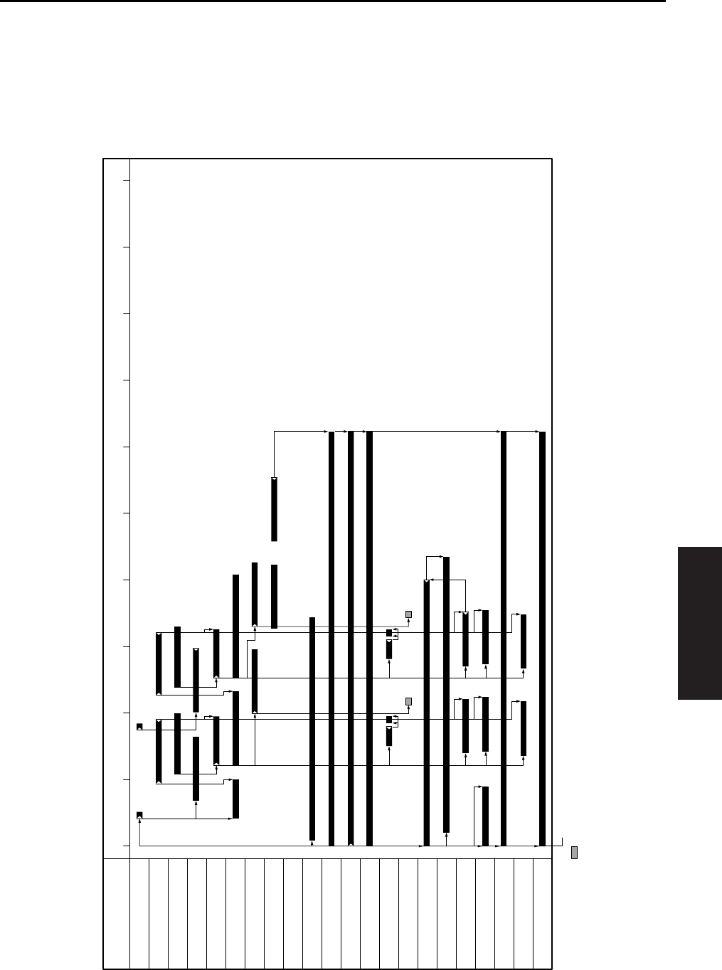
TIMING CHART
4-75
IV DIAGRAMS
5. TIMING CHART
5.1 7145 Timing Chart
A. 8.5x11, life size, 2 copies, feed from tray 1
012345678910
Item
Time (sec)
SD1 (1st paper feed solenoid /U)
PS1 (Registration sensor)
V-Valid
PS21 (Timing sensor /U)
MC1 (Registration clutch)
MC2 (Loop clutch)
PS2 (Fixing exit sensor)
PS23 (IT exit sensor /U)
M9 (Paper feed motor)
M11 (Fixing motor)
M1 (Main motor)
M3 (Developing motor)
SD7 (Separation claw solenoid)
SD4 (Cleaning web solenoid)
HV (Charging corona)
HV (Developing bias)
HV (Transfer corona section)
HV (Separation corona)
PCL (Pre-charging exposure lamp)
TSL (Transfer synchronization lamp)
HV (Paper entrance guide plate)
START button ON
: Does not come ON for some copy counts.
M3 (Developing motor)
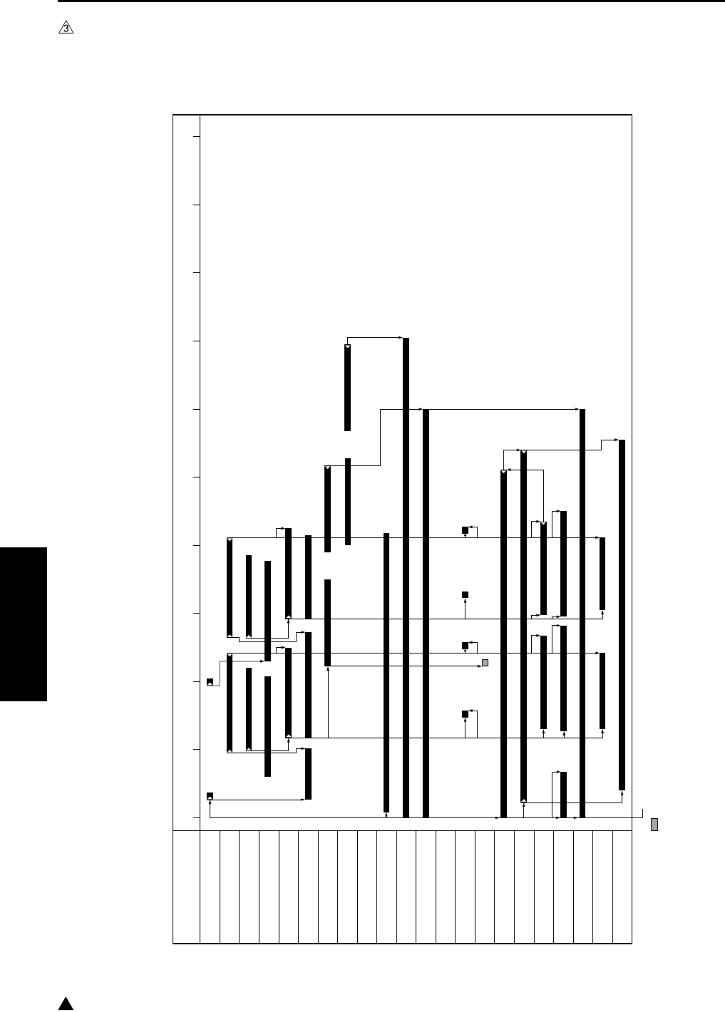
TIMING CHART
4-76
IV DIAGRAMS
3
5.2 7235/7228/7222 Timing Chart
A. 8.5x11, life size, 2 copies, feed from tray 1
Note:
• This timing chart shows the case of 7235.
7322fs4009
012345678910
Item
Time (sec)
SD1 (1st paper feed solenoid /U)
PS1 (Registration sensor)
V-Valid
PS21 (Timing sensor /U)
MC1 (Registration clutch)
MC2 (Loop clutch)
PS2 (Fixing exit sensor)
PS23 (IT exit sensor /U)
M9 (Paper feed motor)
M11 (Fixing motor)
M1 (Main motor)
SD7 (Separation claw solenoid)
SD4 (Cleaning web solenoid)
HV (Charging corona)
HV (Developing bias)
HV (Transfer corona section)
HV (Separation corona)
PCL (Pre-charging exposure lamp)
TSL (Transfer synchronization lamp)
HV (Paper entrance guide plate)
START button ON
: Does not come ON for some copy counts.
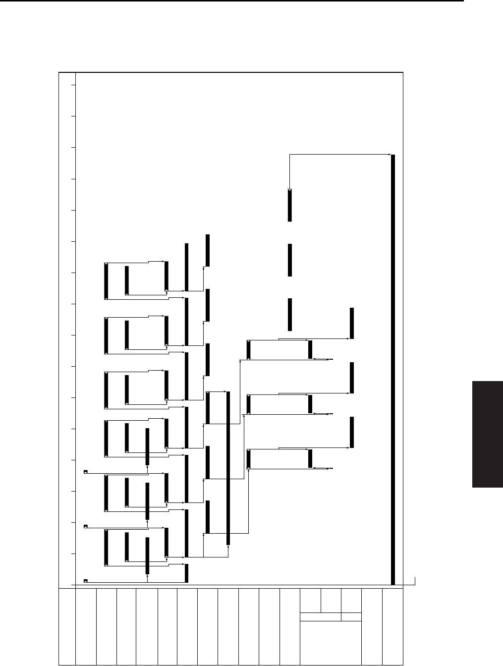
TIMING CHART
4-77
IV DIAGRAMS
5.3 7145 ADU Timing Chart
A. 8.5x11, life size, 3 copies, feed from tray 1
R
600mm/s
F
230mm/s
230mm/s
01234567 9101112131415168
Item
Time (sec)
SD1 (1st paper feed solenoid /U)
PS1 (Registration sensor)
V-Valid
PS21 (Timing sensor /U)
MC1 (Registration clutch)
MC2 (Loop clutch)
PS2 (Fixing exit sensor)
SD5 (ADU gate solenoid)
PS4 (ADU sensor)
PS24 (IT exit sensor /L)
M1 (Main motor)
START button ON
M6 (ADU motor)
600mm/s
230mm/s
230mm/s
F
R
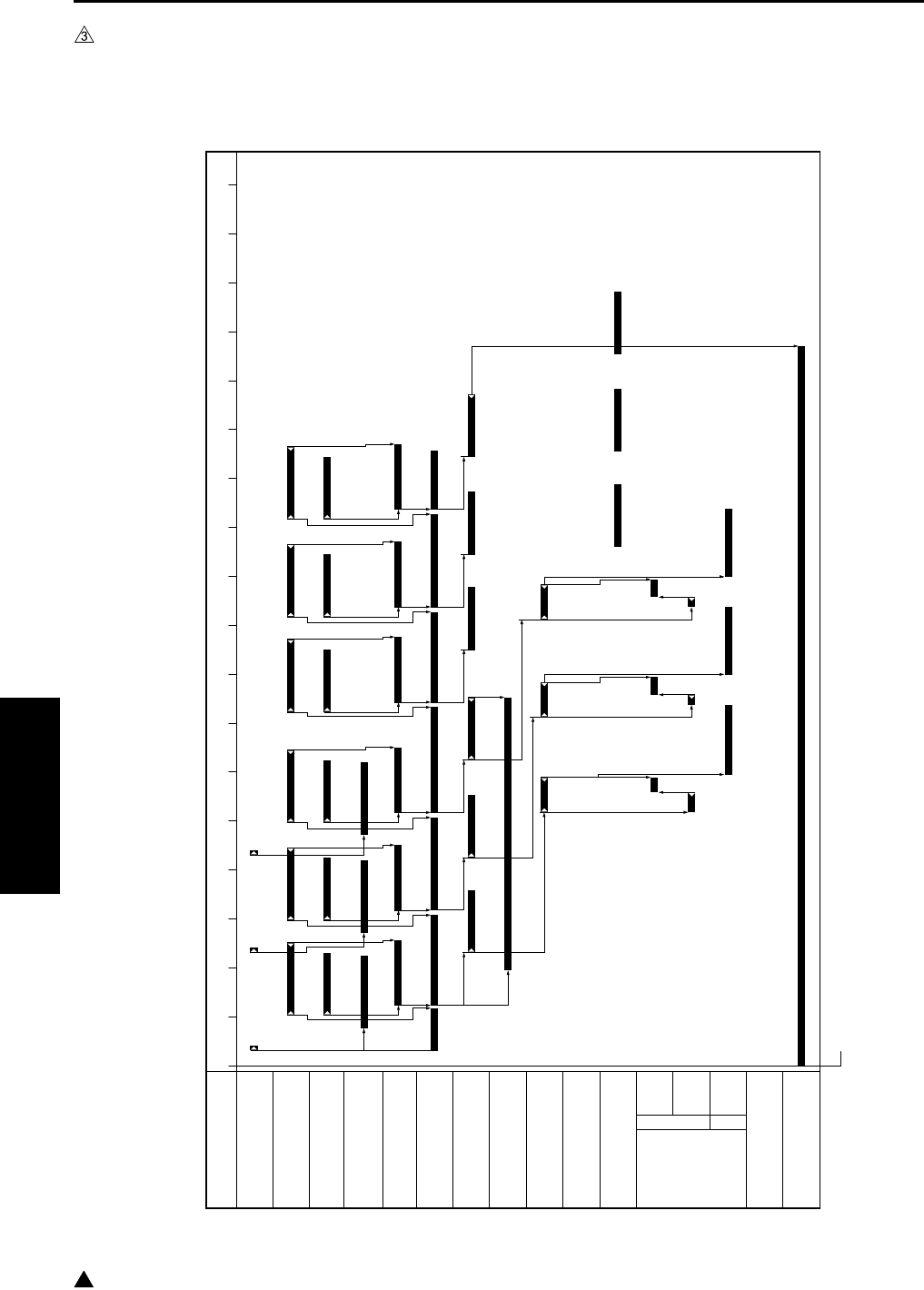
TIMING CHART
4-78
IV DIAGRAMS
3
5.4 7235/7228/7222 ADU Timing Chart
A. 8.5x11, life size, 3 copies, feed from tray 1
Note:
• This timing chart shows the case of 7235.
7322fs4010
0 1 2 3 4 5 6 7 8 9 10 11 12 13 14 15 16 17 18
Item
Time (sec)
SD1 (1st paper feed solenoid /U)
PS1 (Registration sensor)
V-Valid
PS21
(Timing sensor /U)
MC1 (Registration clutch)
MC2 (Loop clutch)
PS2 (Fixing exit sensor)
SD5
(ADU gate solenoid)
PS4 (ADU sensor)
PS24 (IT exit sensor /L)
M1 (Main motor)
START button ON
M6
(ADU motor)
600mm/s
165mm/s*
165mm/s*
F
R
* 165mm/s (7235)
140mm/s (7228/7222
)
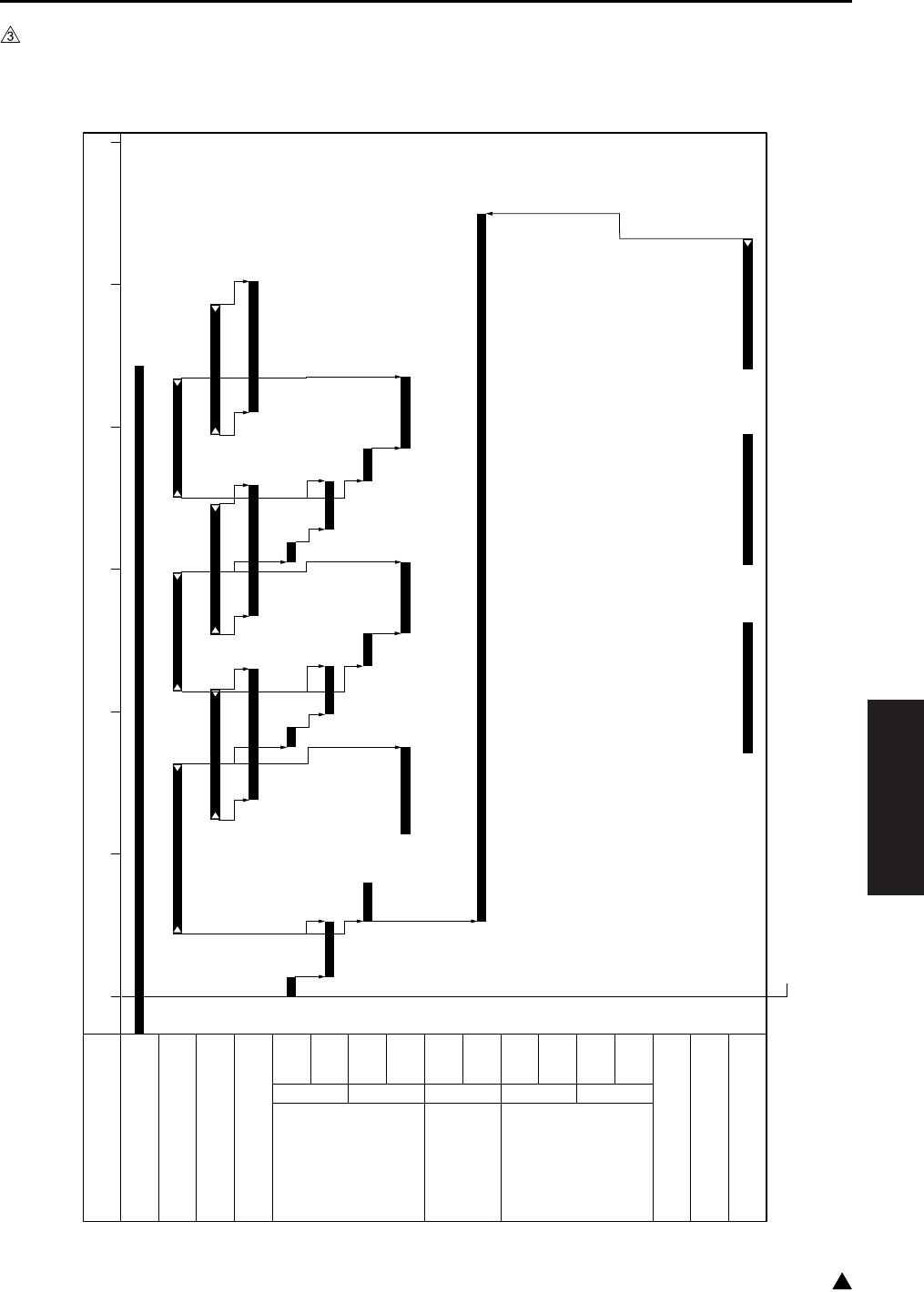
TIMING CHART
4-79
IV DIAGRAMS
3
5.5 DF-318/DF-320 Timing Chart
A. 8.5x11, life size, single side original, 3 sheets
0123456
Item
Time (sec)
PS301 (No original sensor)
PS308 (Original registration sensor)
PS309 (Original conveyance sensor)
Valid (Scan)
M301
(Original feed motor)
100mm/s
250mm/s
460mm/s
F
R
230mm/s
M302 (Original con-
veyance motor)
460mm/s
230mm/s
F
M303
(Original reversal motor)
230mm/s
460mm/s
460mm/s
F
R
230mm/s
SD302 (Roller pressure solenoid)
SD301 (Paper exit solenoid)
PS302 (Original exit sensor)
START button ON
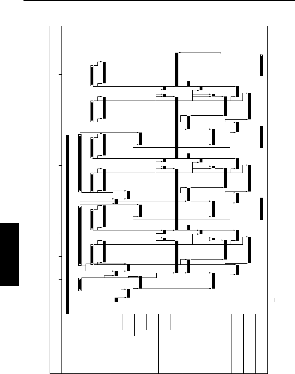
TIMING CHART
4-80
IV DIAGRAMS
B. 8.5x11, life size, double side originals, 3 sheets
0246810135791112
Item
Time (sec)
PS301 (No original sensor)
PS308 (Original registration sensor)
PS309 (Original conveyance sensor)
Valid (Scan)
M301
(Original feed motor)
100mm/s
250mm/s
460mm/s
F
R
230mm/s
M302 (Original con-
veyance motor)
460mm/s
230mm/s
F
M303
(Original reversal motor)
230mm/s
460mm/s
460mm/s
F
R
230mm/s
SD302 (Roller pressure solenoid)
SD301 (Paper exit solenoid)
PS302 (Original exit sensor)
START button ON

TIMING CHART
4-81
IV DIAGRAMS
3
5.6 DB-211/DB-411 Timing Chart
A. 8.5x11, single side, 3 copies, feed from tray 3
Note:
• This timing chart shows the case of 7145.
0123 5674
Item
Time (sec)
M9 (Paper feed motor)
M100 (DB Paper feed motor)
SD101 (Paper feed solenoid/U)
PS1 (Registration sensor)
V-Valid
MC1 (Registration clutch)
MC2 (Loop clutch)
PS104 (Paper feed sensor /U)
PS2 (Fixing exit sensor)
START button ON

TIMING CHART
4-82
IV DIAGRAMS
3
5.7 LT-203 Timing Chart
A. 8.5x1, single side, 3 copies
Note:
• This timing chart shows the case of 7145.
0123 56 874
Item
Time (sec)
M9 (Paper feed motor)
M100 (DB Paper feed motor)
M150 (LT paper feed motor)
SD151 (LT paper feed solenoid)
PS1 (Registration sensor)
V-Valid
MC1 (Registration clutch)
MC2 (Loop clutch)
PS155 (Paper feed sensor)
PS104 (Paper feed sensor /U)
PS2 (Fixing exit sensor)
START button ON
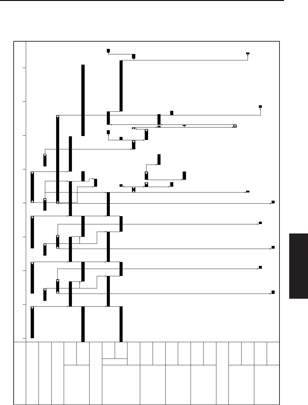
TIMING CHART
4-83
IV DIAGRAMS
5.8 FS-112 Timing Chart
A. 8.5x11, sort mode, 2 originals, 2 sets setting
024681357
Time (sec)
PS2(Main body fixing exit sensor)
PS702 (FNS entrance sensor)
PS703 (Paper exit sensor)
M702
(Paper exit motor)
600mm/s
230mm/s
F
R
SD701 (Roller release solenoid)
M701
(FNS conveyance motor)
600mm/s
230mm/s
M703
(Alignment motor /R)
Alignment/Shift
Open
M704
(Alignment motor /F)
Alignment
Shift/Open
M705
(Stapler movement motor)
F
R
M708 (Stapler motor)
M707
(Paper pressure motor)
Pressure
Release
M706
(Tray up/down motor)
Raise
Lower
Item
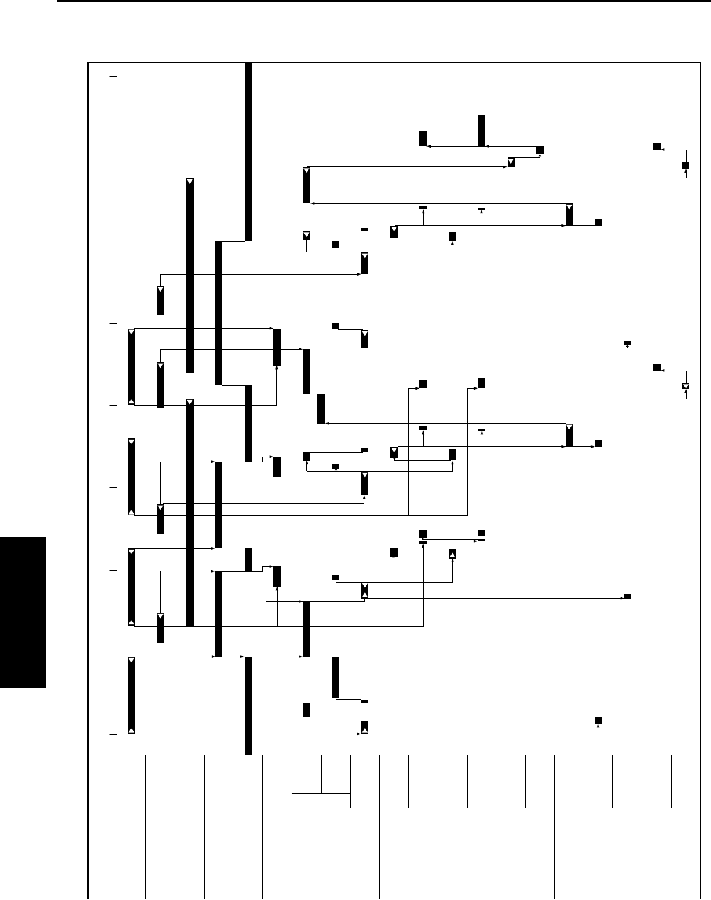
TIMING CHART
4-84
IV DIAGRAMS
B. 8.5x11, staple mode, 2 originals, 1 position, 2 sets setting
024681357
Item
Time (sec)
PS2(Main body fixing exit sensor)
PS702 (FNS entrance sensor)
PS703 (Paper exit sensor)
M702
(Paper exit motor)
600mm/s
230mm/s
F
R
SD701 (Roller release solenoid)
M701
(FNS conveyance motor)
600mm/s
230mm/s
M703
(Alignment motor /R)
Alignment/Shift
Open
M704
(Alignment motor /F)
Alignment
Shift/Open
M705
(Stapler movement motor)
F
R
M708 (Stapler motor)
M707
(Paper pressure motor)
Pressure
Release
M706
(Tray up/down motor)
Raise
Lower
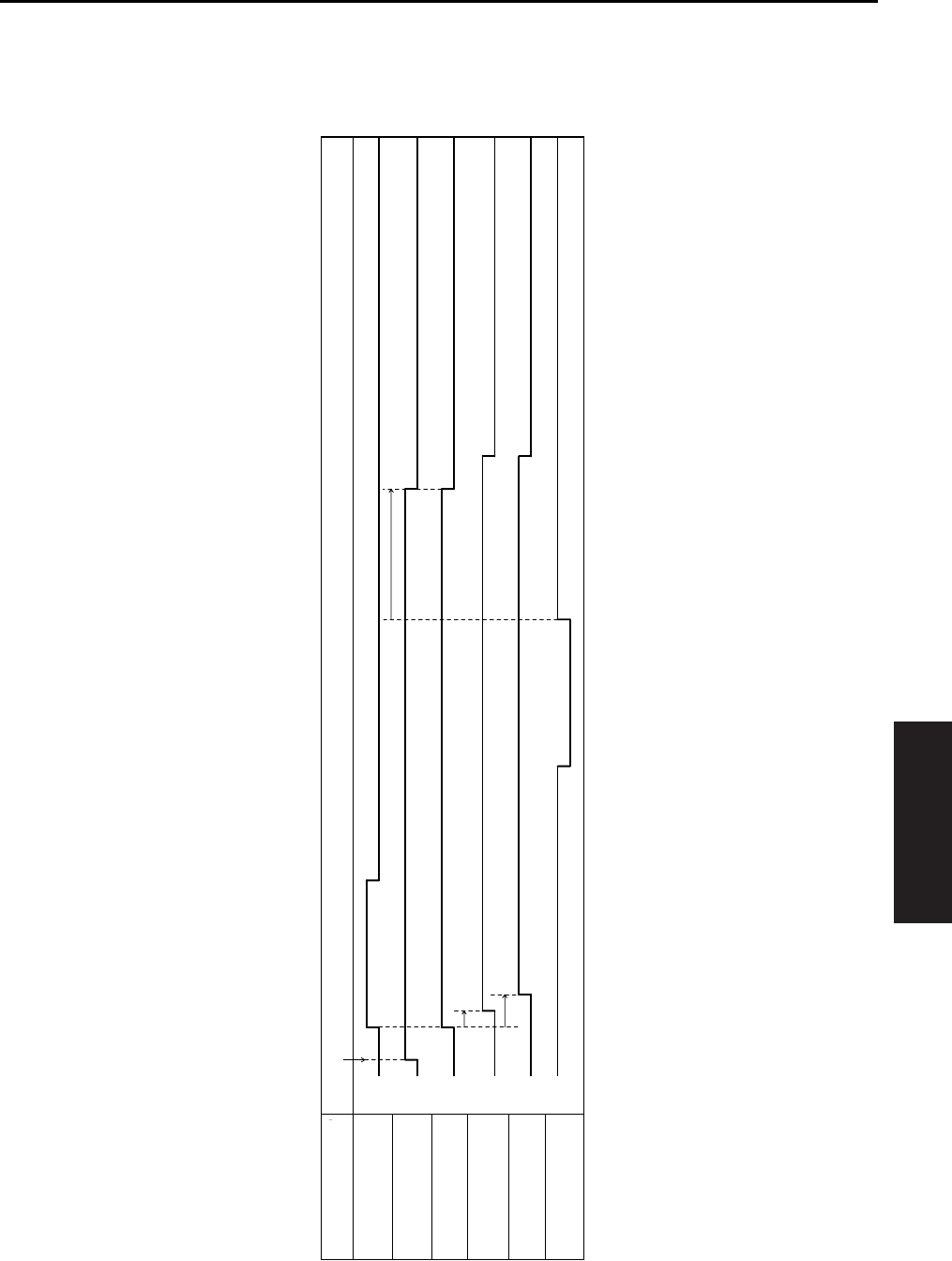
TIMING CHART
4-85
IV DIAGRAMS
5.9 FS-113 Timing Chart
A. Non-sort, 1 original, 1 copy setting
L
H
ON
OFF
ON
OFF
ON
OFF
ON
OFF
L
H
PS2 (Fixing exit sensor)
M1 (Entrance motor)
M4 (Upper entrance motor)
SL1 (Upper/lower entrance
switching solenoid)
SL2 (1st tray entrance
selecting solenoid)
PC1 (1st tray exit sensor)
Item FNS movement starting signal ON
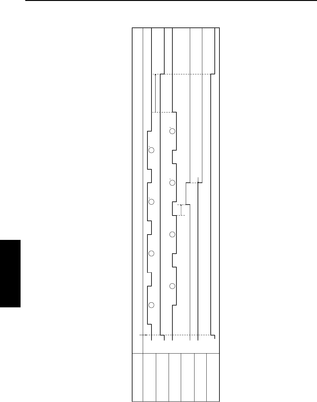
TIMING CHART
4-86
IV DIAGRAMS
B. Sort, 2 originals, 2 sets setting
1
1
1
1
2
2
2
2
L
H
ON
OFF
L
H
ON
OFF
H
L
PS2 (Fixing exit sensor)
M1 (Entrance motor)
PC3 (Storage sensor)
M8 (Shift motor)
PC10 (Shift home position sensor)
M3 (Exit motor)
Item FNS movement starting signal ON
Shift position
Forward
rotation
Stop
Backward
rotation
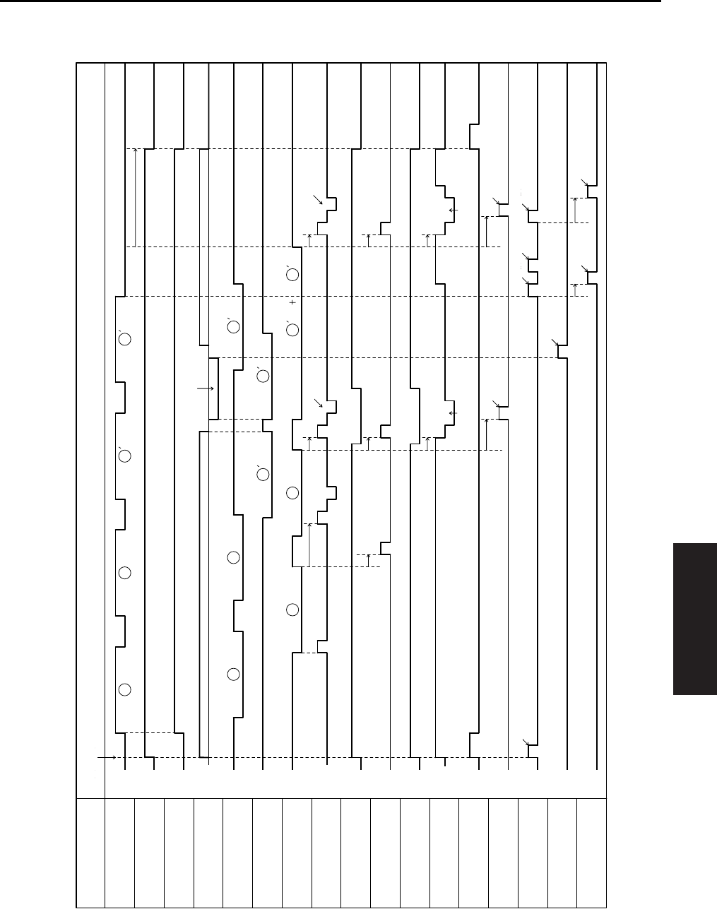
TIMING CHART
4-87
IV DIAGRAMS
C. Rear corner stapling, 8.5x11R, 2 originals, 2 sets setting
1 1
1
1 1
1 1
2 2
2
2
2
2
L
H
L
H
L
H
ON
OFF
ON
OFF
ON
OFF
ON
OFF
ON
OFF
ON
OFF
ON
OFF
ON
OFF
ON
OFF
ON
OFF
H
L
PS2 (Fixing exit sensor)
M1 (Entrance motor)
M4 (Upper entrance motor)
M2 (Lower entrance motor)
PC4 (Upper entrance sensor)
PC2 (Lower entrance sensor)
FNS movement starting signal ON
PC3 (Storage sensor)
M5 (CD aligning motor)
M15 (Upper paddle motor)
SL3 (Upper paddle solenoid)
M9 (Lower paddle motor)
M3 (Exit motor)
M6 (Stapling unit moving motor)
Stapling motor1
M13 (Exit roller/rolls spacing motor)
M12 (Storage roller/
rolls spacing motor)
M8 (Shift motor)
Item
Spacing
Forward
rotation
Stop
Backward
rotation
Forward
rotation
Stop
Backward
rotation
Forward
rotation
Stop
Backward
rotation
Switchback
Aligning Aligning
Transport to finisher trayTransport to finisher tray
Stapling Stapling
Pressure Spacing Pressure
Shift
Shift
Spacing
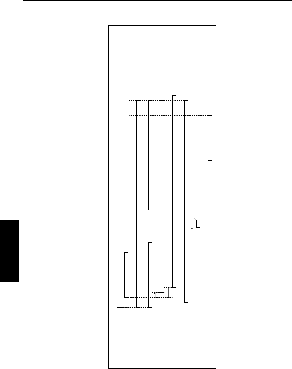
TIMING CHART
4-88
IV DIAGRAMS
D. Non-sort, hole punch, 1 original, 1 copy setting
L
H
L
H
ON
OFF
ON
OFF
ON
OFF
ON
OFF
ON
OFF
ON
OFF
PS2 (Fixing exit sensor)
M1 (Entrance motor)
M4 (Upper entrance motor)
SL1 (Upper/lower entrance
switching solenoid)
SL2 (1st tray entrance
selecting solenoid)
M11 (Punch motor)
Item FNS movement starting signal ON
Punch clutch
PC1 (1st tray exit sensor)
Punching movement

TIMING CHART
4-89
IV DIAGRAMS
1
5.10 FS-114 Timing Chart
A. Non-sort, 8.5x11, 1 copy setting
4349T506BA
ON
OFF
Transport sensor
(PC5-FN)
Forward
Stop
Entrance motor
(M3-FN)
High
Low
Stop
Transport motor
(M2-FN)
Forward
Stop
Exit motor
(M1-FN)
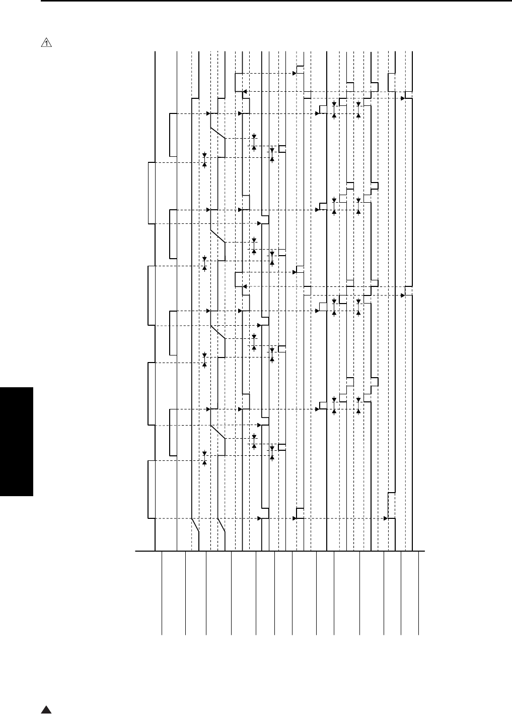
TIMING CHART
4-90
IV DIAGRAMS
1
B. 1 staple, 2 holes, 8.5x11, 2 originals, 2 sets setting
4349T505BA
Punch sensor ON
OFF
Storage tray detecting sensor
(PC8-FN)
ON
OFF
Entrance motor
(M3-FN)
Forward
Stop
Transport motor
(M2-FN)
High
Low
Stop
Exit motor
(M1-FN)
Forward
Stop
Backward
Registration clutch
(CL1-FN)
ON
OFF
Punch drive motor Forward
Stop
Exit open/close motor
(M6-FN)
Forward (Retraction)
Stop
Backward (Pressure)
Storage paddle solenoid
(SL1-FN)
ON
OFF
Alignment motor 1
(M4-FN)
Forward
Stop
Backward
Alignment motor 2
(M5-FN)
Forward
Stop
Backward
Stapling unit moving moto
r
(M7-FN)
Forward
Stop
Stapler motor Forward
Stop
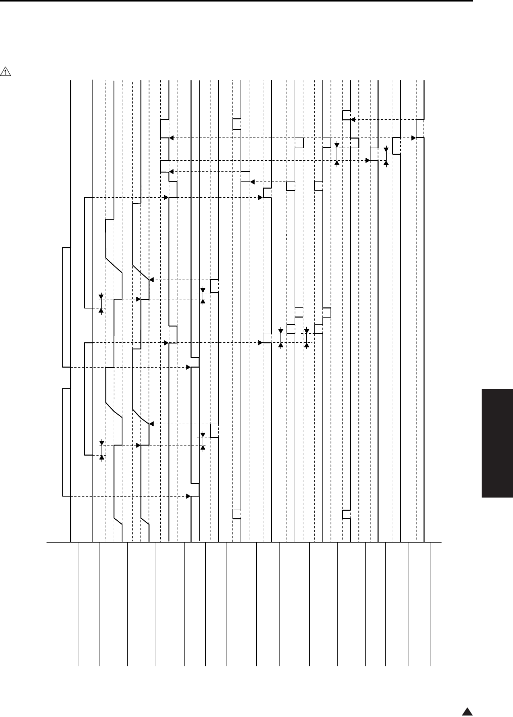
TIMING CHART
4-91
IV DIAGRAMS
1
5.11 SK-114 Timing Chart
A. Booklet-binding, 2-point stapling, 8.5x11R, 2 originals, 1 set setting
4511T504BA
Punch sensor ON
OFF
Storage tray detecting sensor
(PC8-FN)
ON
OFF
Transport motor
(M2-FN)
High
Low
Stop
Exit motor
(M1-FN)
Forward
Stop
Backward
Registration clutch
(CL1-FN)
ON
OFF
Crease motor
(M10-SK)
Forward
Stop
Exit open/close motor
(M6-FN)
Forward
Stop
Backward
Entrance motor
(M3-FN)
High
Low
Stop
Storage paddle solenoi
d
(SL1-FN)
ON
OFF
Alignment motor 1
(M4-FN)
Forward
Stop
Backward
Alignment motor 2
(M4-FN)
Forward
Stop
Backward
Saddle exit open/close motor
(M9-SK)
Forward
Stop
Backward
Stapler motor 1
Forward
Stop
Stapler motor 2
Forward
Stop
Saddle exit motor
(M8-SK)
Forward
Stop
1st Document 2nd Document

TIMING CHART
4-92
IV DIAGRAMS
Blank page
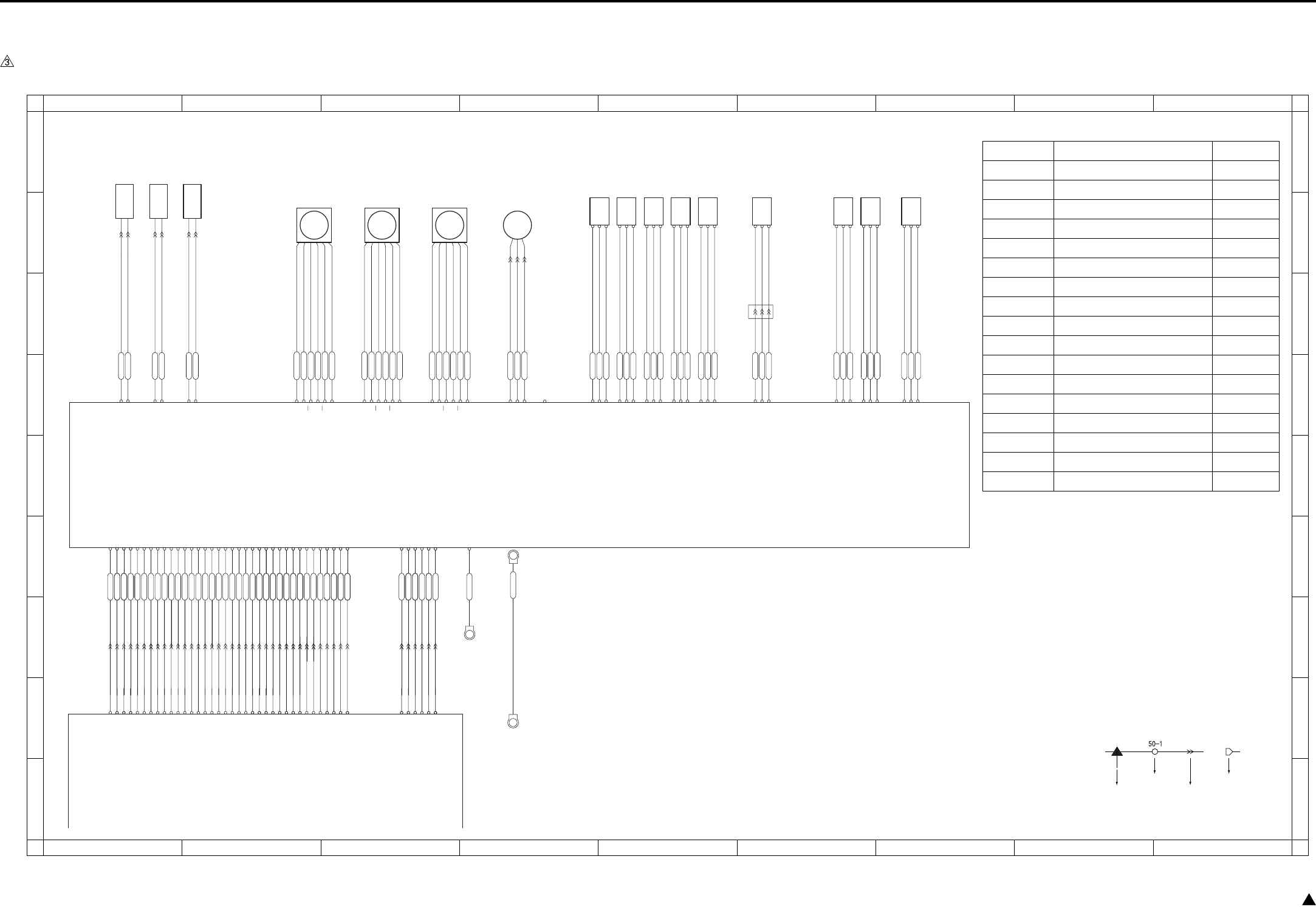
OVERALL WIRING DIAGRAM
4-93 3
6. OVERALL WIRING DIAGRAM
6.1 DF-318/320 Overall Wiring Diagram
CN245-3
CN245-2
CN245-1
CN232-1
CN232-2
CN231-1
CN231-2
CN246-3
CN246-2
CN246-1
CN253-3
CN253-2
CN253-1
CN201-A14
CN201-B 6
CN201-B 7
CN201-B 8
CN201-B15
CN201-B16
CN201-B17
CN201-B18
CN201-A 1
CN201-A 2
CN201-A 3
CN201-A 4
CN201-A 5
CN201-A 6
CN201-A 7
CN201-A 8
CN201-A 9
CN201-A10
CN201-A11
CN201-A12
CN201-A13
PS306
PS305
CN243-3
CN243-2
CN243-1
CN242-3
CN242-2
CN242-1
PS301
PS302
PS303
CN241-3
CN241-2
CN241-1
CN249-1
CN249-2
CN249-3
CN202-3
CN202-2
CN202-1
CN248-3
CN248-2
CN248-1
PS304
PS308
PS309
CN244-3
CN244-2
CN244-1
CN202-1
CN202-3
CN202-2
SD302
SD301
CN233-1
SD303
CN233-2
VR301
CN201-B11
CN201-B12
CN201-B13
CN201-B14
CN201-B10
CN201-B 9
CN200- 6
CN200- 2
CN200- 4
CN200- 5
CN201-A15
CN201-B 3
CN201-B 4
CN201-A17
CN201-A16
CN201-B 2
CN201-B 1
CN65- 6 24V
CN65- 5 24V
CN17-B11 M303 CLOCK
CN17-B13 M303 F/R
CN17-A 5 M301 RST
CN17-A 3 M301 F/R
CN17-B17 M302 CLOCK
CN17-A 1 M301 CLOCK
CN17-A14 VR301
CN17-A13 PS305
CN17-A12 PS304
CN17-A11 PS303
CN17-A10 PS302
CN17-A 9 PS301
CN17-A 8 SD301 CONT
CN17-A 7 SGND
CN17-A 4 M301 LOCK
CN17-A 2 SGND
CN17-B16 SGND
CN17-B15 M302 LOCK
CN17-B 6 PS306
CN17-B14 M303 LOCK
CN17-B12 SGND
CN17-B10 SGND
CN17-B 9 SD302 DRIVE
CN17-B 8 PS309
CN17-B 7 PS308
CN201-B 8
CN201-B 7
CN201-B 6
CN201-B 5
CN201-B 9
CN201-B10
CN201-B11
CN201-B 4
CN201-A 4
CN201-B 3
CN201-B 2
CN201-B 1
CN201-A17
CN201-A16
CN201-A15
CN201-A14
CN201-A13
CN201-A12
CN201-A11
CN201-A10
CN201-A 9
CN201-A 8
CN201-A 7
CN201-A 6
CN201-A 5
CN201-B12
CN201-B13
CN201-B15
CN201-A 1
CN201-A 2
CN201-A 3
CN201-B16
CN201-B17
CN17-B 4 M303 V0
CN17-B 3 M302 V1
CN17-B 2 M302 V0
CN17-B 1 M301 V0
CN65- 1 SGND
CN65- 2 5V
CN65- 4 PGND
CN65- 3 PGND
Original conveyance
sensor
Original size VR
Original size
sensor/1
Original size
sensor/2
No original sensor
Original exit sensor
DF open/close
sensor
Cover open/close
sensor
Original registration
sensor
Roller pressure
solenoid
Exit solenoid
CN214-A 2 24V
CN214-A 5 DRIVE
CN214-A 3 24V
CN214-A 6 DRIVE
CN214-A 1 24V
CN214-A 4 DRIVE
CN215- 3 5V
CN215- 2 PS
CN215- 1 SGND
CN215- 6 5V
CN215- 5 PS
CN215- 4 SGND
CN215- 9 5V
CN215- 8 PS
CN215- 7 SGND
CN215- 12 5V
CN215- 11 PS
CN215- 10 SGND
CN215- 15 5V
CN215- 14 PS
CN215- 13 SGND
CN215- 16 5V
CN215- 17 PS
CN215- 18 SGND
CN216- 6 5V
CN216- 5 PS
CN216- 4 SGND
CN216- 3 5V
CN216- 2 PS
CN216- 1 SGND
CN213- 1 5V
CN213- 2 VR
CN213- 3 SGND
CN212- 1 24V
CN212- 2 24V
CN212- 3 PGND
CN212- 4 PGND
CN200- 3
CN212- 5 5V
CN200- 1 CN212- 6 SGND
CN212- 7 FG ND
CN211-A 5 VR301
CN211-A 6 PS305
CN211-A 7 PS304
CN211-A 8 PS303
CN211-A 9 PS302
CN211-A10 PS301
CN211-A11 SD301 CONT
CN211-A12 SGND
CN211-A18 M301 CLOCK
CN211-A16 M301 F/R
CN211-A17 SGND
CN211-A15 M301 LOCK
CN211-A14 M301 RST
CN211-B 4 M302 LOCK
CN211-B11 PS309
CN211-B12 PS308
CN211-A 4 SD303
CN211-A 2 FM301 LOCK
CN211-B10 SD302 DRIVE
CN17-A17 FM301
CN17-A16 FM301
CN17-A15 SD303
CN201-B18
CN201-A18
CN17-A18 5V
CN201-A18
CN17-B 5 M303 V1 CN201-B14 CN201-B 5
CN17-B18 SGND
CN211-B18 M301 V0
CN211-B17 M302 V0
CN211-B16 M302 V1
CN211-B15 M303 V0
CN211-B14 M303 V1
CN211-B13 PS306
CN211-B 9 SGND
CN211-B 8 M303 CLOCK
CN211-B 7 SGND
CN211-B 6 M303 F/R
CN211-B 5 M303 LOCK
CN211-B 3 SGND
CN211-B 2 M302 CLOCK
CN211-B 1 SGND
CN211-A 1 5V
Stamp solenoid
CN17-A 6 M301 RTN CN211-A13 M301 RTN
CN211-A 3 FM301 ON
M301
CN221-2
CN221-5
CN221-1
CN221-3
CN221-6
CN221-4
M302
CN222-2
CN222-5
CN222-1
CN222-3
CN222-6
CN222-4
M303
CN223-2
CN223-5
CN223-1
CN223-3
CN223-6
CN223-4
Original feed motor
Original conveyance
motor
Original reverse motor
CN214-B 5 24V
CN214-B 6 24V
CN214-B 1 B
CN214-B 2 B
CN214-B 3 A
CN214-B 4 A
CN214-B 7 24V
CN214-B 8 24V
CN214-A11 B
CN214-A12 B
CN214-A13 A
CN214-A14 A
CN214-B 9 24V
CN214-B10 24V
CN214-A 7 B
CN214-A 8 B
CN214-A 9 A
CN214-A10 A
FM301
CN224-3
CN224-2
CN224-1 Cooling fan
CN214-B12 DRIVE
CN214-B13 LOCK
CN214-B14 PGND
N.C
CB(MAIN BODY)
DFDB
1
A
B
C
D
E
F
G
H
I
A
B
C
D
E
F
G
H
I
23456789
123456789
Symbol
Crimp
Connector Faston
Relay connector
Symbol Part name Location
DFDB DF drive board 1-D
M301 Original feed motor 2-B
M302 Original conveyance motor 3-B
M303 Original reverse motor 3-B
FM301 Cooling fan 4-B
SD301 Exit solenoid 1-A
SD302 Roller pressure solenoid 1-A
SD303 Stamp solenoid 2-A
PS301 No original sensor 4-B
PS302 Original exit sensor 5-B
PS303 DF open/close sensor 5-B
PS304 Cover open/close sensor 5-B
PS305 Original size sensor/1 6-B
PS306 Original size sensor/2 6-B
PS308 Original registration sensor 5-B
PS309 Original conveyance sensor 6-B
VR301 Original size VR 7-B
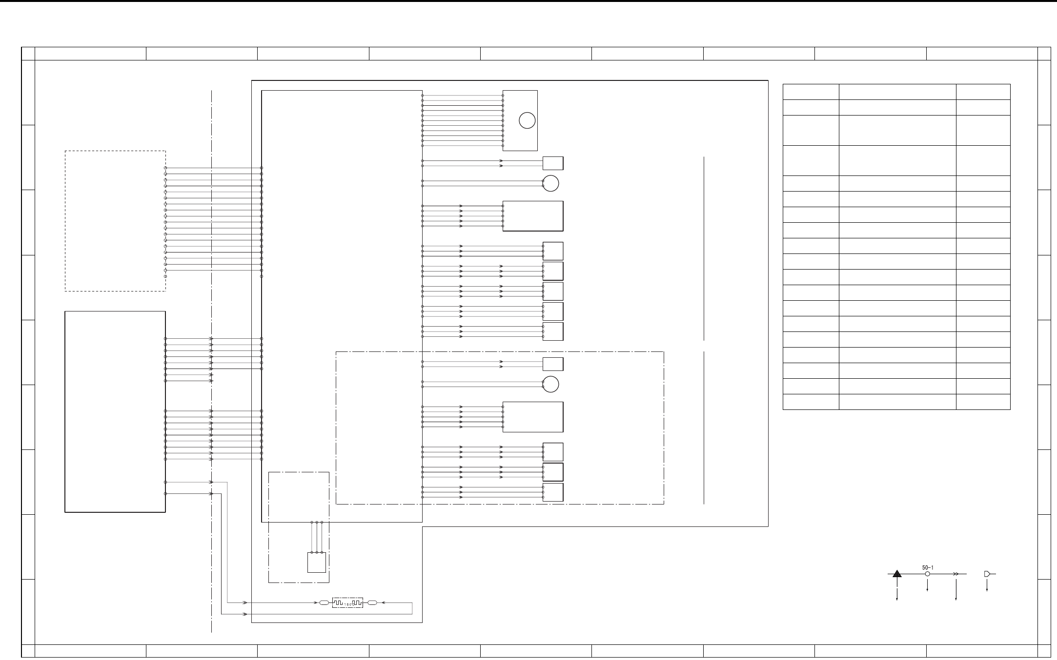
OVERALL WIRING DIAGRAM
4-94
6.2 DB-211/411 Overall Wiring Diagram
PTC
HTR 100
Internal heater
24V2 7-5 100-1 24V2
100-2 24V2
100-5 5V
100-3 PGND
100-4 PGND
100-6 SGND
J60:5 -
J60:6 -
J60:3 -
J60:4 -
J60:7 -
J60:8 -
J60:9 -
J60:10-
3
4
7
8
9
10
6
5
24V2 7-6
PGND 7-7
PGND 7-8
RL PW 7-25
RL PG 7-26
5V2 7-10
SGND 7-14
19- 9
19- 8
19- 7
19- 6
19- 5
19- 4
19- 3
19- 2
19- 1 J61: 9 -
J61: 8 -
J61: 7 -
J61: 6 -
J61: 5 -
1
2
3
4
5
J61: 4 -
J61: 3 -
J61: 2 -
J61: 1 -
6
7
8
9 101- 2 LCT.EXIT
101- 3 DB.EXIT
101- 1 DB.RST
101- 4 DB.TXD
101- 5 GND
101- 6 DB.CTS
101- 7 DB.RXD
101- 8 GND
101- 9 DB.RTS
J80:1-
J80:2-
1
2 J120-2J120-1
J60:1 -
J60:2 -
1
2
24V1 7-1
PGND 7-3
DB-411
Only
MAIN BODY
Remaining
paper sensor
PS
109
119-3
-1
-2
105-1 SGND
105-3 5V
105-2 SET
102-6 NC
102-11 5V
102-3 PGND
102-4 PGND
102-10 SGND
110-11
-10
-9
-8
-7
-6
-5
-4
-3
-2
-1
102-5 NC
102-9 ON2
102-8 CLOCK
102-7 F/R DB paper feed motor
102-1 24V2
102-2 24V2
SD
101
103-A1 24V2 113: 1 - 2
1113: 2 -
103-A2 DRIVE Paper feed solenoid/U
111- 2
111- 1
M101
M100
PSDTB/3
PSDTB/4
103-A4 24V2 Tray up drive motor/3
103-A3 DRIVE
PS
105
J64: 2- 7
6J64: 3-
J64: 1- 8
117- 3
- 2
- 1
103-A10 SGND
103-A12 5V
103-A11 PS Paper feed sensor/L
PS
102
J63: 5- 2
1J63: 6-
J63: 4- 3
114- 3
- 2
- 1
J69: 6-
J69: 5- 2
1
J69: 4- 3 Tray upper limit sensor/3
103-B1 SGND
103-B3 5V
103-B2 PS
PS
103
J63: 2-
4J63: 3-
J63: 1- 6
115- 3
- 2
- 1
J69: 3-
J69: 2- 5
4
J69: 1- 6
5 No paper sensor/3
103-B4 SGND
103-B6 5V
103-B5 PS
PS
104
J68: 2- 2
1J68: 3-
J68: 1- 3
116- 3
- 2
- 1 Paper feed sensor/U
103-B7 SGND
103-B9 5V
103-B8 PS
PS
101
J66: 2- 2
1J66: 3-
J66: 1- 3
112- 3
- 2
- 1 Tray sensor/3
103-B10 SGND
103-B12 5V
103-B11 PS
SD
102
104-1 24V2 123: 1 - 2
1123: 2 -
104-2 DRIVE Paper feed solenoid/L
121- 2
121- 1
M102
104-4 24V2 Tray up drive motor/4
104-3 DRIVE
PS
107
J65: 5- 7
6J65: 6-
J65: 4- 8
124- 3
- 2
- 1
J70: 6-
J70: 5- 2
1
J70: 4- 3 Tray upper limit sensor/4
104-10 SGND
104-12 5V
104-11 PS
PS
108
J65: 2-
J65: 3-
J65: 1-
125- 3
- 2
- 1
J70: 3-
J70: 2- 5
4
J70: 1- 6
10 No paper sensor/4
9
11
103-13 SGND
104-15 5V
104-14 PS
PS
106
J67: 2- 2
1J67: 3-
J67: 1- 3
122- 3
- 2
- 1 Tray sensor/4
104-16 SGND
104-18 5V
104-17 PS
118- 5
- 4
- 3
- 2
- 1
103-A5 SIZE.D
103-A7 SIZE.B
103-A6 SIZE.C
103-A8 SIZE.A
103-A9 SELECT
J64: 8- 1
2J64: 7-
J64: 6-
J64: 5-
J64: 4- 5
4
3 Paper size detection board
126- 5
- 4
- 3
- 2
- 1
104-5 SIZE.D
104-7 SIZE.B
104-6 SIZE.C
104-8 SIZE.A
104-9 SELECT
J65:11- 1
2J65:10-
J65: 9-
J65: 8-
J65: 7- 5
4
3 Paper size detection board
TRAY4
DB-211
only
TRAY3
PS152 110- 7
PS153 110- 6
PS154 110- 5
PS151 110- 4
LCT_TYPE 110- 3
106-18 5V 110- 2
PS155 110- 8
SD151 DRIVE 110- 9
M150 CONT 110-10
M150 CLOCK 110-11
M150 F/R 110-12
LT CLOSE 110-13
M151 DRIVE 110-14
PGND 110-15
PGND 110-16
24V2 110-17
24V2 110-18
24V2 110-19
LT-203
106- 1 24V2
106- 2 24V2
106- 3 24V2
106- 4 PGND
106- 7 LT CLOSE
106-10 M150 CONT
106-11 SD151 DRIVE
106-12 PS155
106-13 PS152
106-14 PS153
106-15 PS154
106-19 SGND
SGND 110- 1
106-18 5V
106-17 LCT_TYPE
106-16 PS151
106- 9 M150 CLOCK
106- 8 M150 F/R
106- 6 M151 DRIVE
106- 5 PGND
DBDB
1
A
B
C
D
E
F
G
H
I
A
B
C
D
E
F
G
H
I
23456789
123456789
Symbol
Crimp
Connector Faston
Relay connector
Symbol Part name Location
LT-203 LT-203 1-B
PSDTB/3 Paper size detection
board /3
5-C
PSDTB/4 Paper size detection
board /4
5-F
M100 DB paper feed motor 5-A
M101 Tray up drive motor /3 5-B
M102 Tray up drive motor /4 5-E
SD101 Paper feed solenoid /U 5-B
SD102 Paper feed solenoid /L 5-E
PS101 Tray sensor /3 5-E
PS102 Tray upper limit sensor /3 5-D
PS103 No paper sensor /3 5-D
PS104 Paper feed sensor /U 5-D
PS105 Paper feed sensor /L 5-C
PS106 Tray sensor /4 5-G
PS107 Tray upper limit sensor /4 5-F
PS108 No paper sensor /4 5-G
PS109 Remaining paper sensor 3-H
HTR100 Internal heater 3-I

OVERALL WIRING DIAGRAM
4-95
6.3 LT-203 Overall Wiring Diagram
PTC
Internal heater
HTR 150
(LD)
112-12 5V
112-6 PGND
112-8 F/R
112-11 SGND
120-11
-10
-9
-8
-7
-6
-5
-4
-3
-2
-1
112-9 CLOCK
112-10 CONT
(H/L)
112-4 24V2
112-5 24V2
112-7 PGND
M150
LT paper feed motor
(CN113:miniCT)
121- 1
121- 2
M151
112-1 24V
112-2 DRIVE
112-3 PGND
Tray up drive motor
1
2
J121-2
J121-1
1
2
DB-211
DB-411
DBDB
LTDB
J80 :1 -
J80 :2 -
J120 :2 -
MAIN BODY
DCPS
DB
PTC HEATER
J120 :1 -
SD
151
2
1
113- 2 DRIVE J84: 1 -
J84: 2 -
2
1J82: 5-
J82: 4- LT paper feed solenoid
113- 1 24V2
106-10 M150 CONT
106-11 SD151 DRIVE
106-12 PS155
106-13 PS152
106-16 PS151
106-15 PS154
106-14 PS153
106- 4 PGND
106- 2 24V2
106- 1 24V2
106- 9 M150 CLOCK
106- 5 PGND
106-19 SGND
106-18 5V
106-17 SGND
106- 8 M150 F/R
106- 7 LT CLOSE
106- 6 M151 DRIVE
106- 3 24V2
110- 7 PS152
110- 4 PS151
110- 6 PS153
110-16 PGND
110-18 24V2
110-19 24V2
110- 5 PS154
110-10 M150 CONT
110-11 M150 CLOCK
110-15 PGND
110- 1 SGND
110- 2 5V
110- 8 PS155
110- 9 SD151 DRIVE
110-12 M150 F/R
110-13 LT CLOSE
110-14 M151 DRIVE
110-17 24V2
110- 3 SGND
PS
154
126- 3
- 2
- 1 Remaining paper sensor/1
113-13 PS
113-12 SGND
113-14 5V
PS
151
122- 3
- 2
- 1 Remaining paper sensor/2
113-16 PS
113-17 5V
113-15 SGND
113- 4 PS
113- 3 SGND
113- 5 5V
J82: 3-
J82: 2-
J82: 1-
PS
155
127- 3
- 2
- 1 Paper feed sensor
3
4
5
No paper sensor
5
4
6
PS
153
124- 3
- 2
- 1
113-10 PS J83: 1-
J83: 2-
J83: 3-
113- 9 SGND
113-11 5V
PS
152
125- 3
- 2
- 1
1
2
3 Tray upper limit sensor
J83: 6-
J83: 5-
J83: 4-
113- 7 PS
113- 6 SGND
113- 8 5V
MS151
Interlock switch
114-1 24V
114-2 PGND
114-3 24V2 FT102(4pin)
FT101(1pin)
NC (2pin)
1
A
B
C
D
E
F
G
H
I
A
B
C
D
E
F
G
H
I
23456789
123456789
Symbol
Crimp
Connetcor Faston
Relay connector
Symbol Part name Location
DB-211 DB-211 1-B
DB-411 DB-411 1-B
M150 LT paper feed motor 6-C
M151 Tray up drive motor 6-B
SD151 LT paper feed sole-
noid
6-D
PS151 Remaining paper
sensor /2
6-F
PS152 Tray upper limit
sensor
6-E
PS153 No paper sensor 6-E
PS154 Remaining paper
sensor /1
6-F
PS155 Paper feed sensor 6-D
MS151 Interlock switch 6-A
HTR150 Internal heater 4-G

OVERALL WIRING DIAGRAM
4-96
Blank page
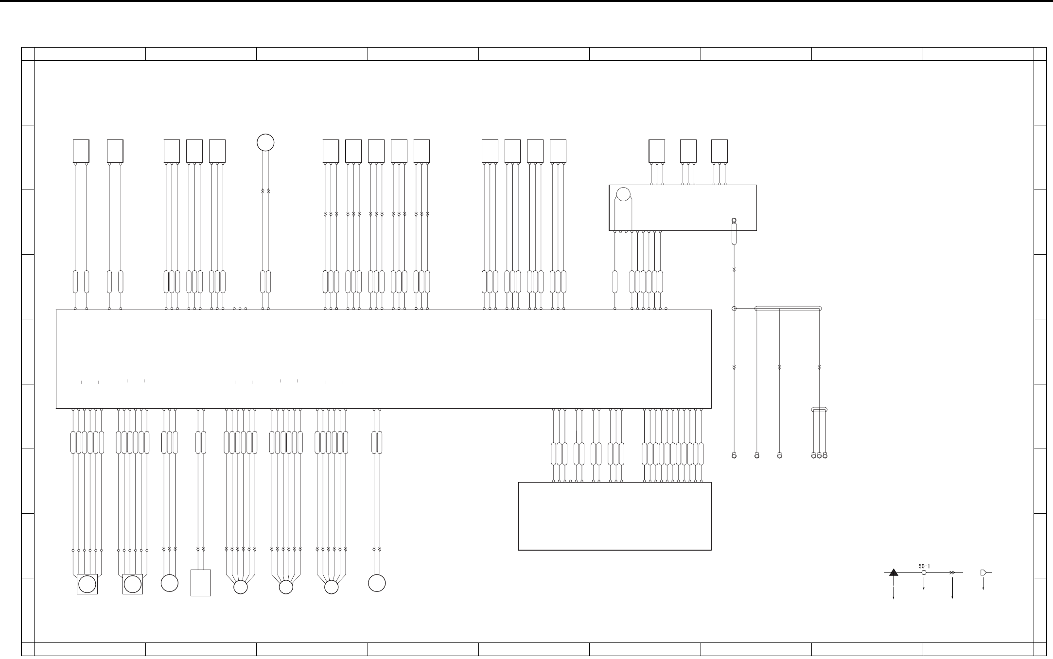
OVERALL WIRING DIAGRAM
4-97
6.4 FS-112 Overall Wiring Diagram
MS702 Shutter switch
CN701-1 24V
CN701-2 24V
CN701-3 24V
CN701-4 5V
CN701-5 5V
CN701-6 SGND
CN701-7 SGND
CN701-8 PGND
CN701-9 PGND
CN701-10 PGND
CN702-11 SGND
CN702-10 SGND
CN702-9 MACK/FSCTS
CN702-8 SGND
CN702-7 SREQ/NC
CN702-6 MRXD/FSSIN
CN702-5 SGND
CN702-4 SACK/FSRTS
CN702-3 MREQ/NC
CN702-2 SGND
CN702-1 MTXD/FSOUT
CN300-A10 24V
CN300-A9 24V
CN300-A8 24V
CN300-A11 NC
CN300-A4 5V
CN300-A3 5V
CN300-A2 SGND
CN300-A1 SGND
CN300-A7 PGND
CN300-A6 PGND
CN300-A5 PGND
CN300-B1 SGND
CN300-B2 SGND
CN300-B3 MACK/FSCTS
CN300-B4 SGND
CN300-B5 SREQ/NC
CN300-B6 MRXD/FSSIN
CN300-B7 SGND
CN300-B8 SACK/FSRTS
CN300-B9 MREQ/NC
CN300-B10 SGND
CN300-B11 MTXD/FSOUT
CN703-8 B
CN703-6 A
CN703-5 A
CN703-7 B
CN703-1 24V3
CN703-2 24V3
CN723-6
CN723-2
CN723-3
CN723-5
CN723-1
CN723-4
CN703-11 B
CN703-12 B
CN703-9 A
CN703-10 A
CN703-3 24V4
CN703-4 24V4
CN724-1
CN724-5
CN724-3
CN724-2
CN724-6
CN724-4
CN705-6 B
CN705-2 24V4
CN705-3 A
CN705-4 A
CN705-1 24V4
CN705-5 B
CN725-4
CN725-6
CN725-2
CN725-3
CN725-5
CN725-1
CN704-7 B
CN704-5 A
CN704-6 A
CN704-8 B
CN704-1 24V1
CN704-2 24V1
M701
FNS
conveyance
motor
CN704-9 A
CN704-11 B
CN704-12 B
CN704-10 A
CN704-3 24V2
CN704-4 24V2
CN746-2
CN746-3
CN746-1
CN713-1 LOCK
CN713-3 PGND
CN713-2 24V
Paper exit
motor M702
CN721-9
CN721-7
CN721-5
CN721-3
CN721-1
CN721-11
CN722-5
CN722-3
CN722-1
CN722-11
CN722-9
CN722-7
FM701
Cooling motor
CN710-2 DRIVE2
CN710-1 DRIVE1
1
2
M706
Tray up/down
motor
Pressure motor
M707
CN730-1
CN730-2
Alignment
motor/R
M703
Alignment
motor/F
M704
Stapler
movement
motor
M705
CN734-1
CN734-2
CN734-3
Tray upper limit sensor
PS711
Paper exit sensor
PS703
Paper exit full sensor
PS704
Tray count sensor
PS716
Tray lower limit sensor
PS706
CN716-2 PGND
CN716-1 DRIVE
CN762-1
CN762-2
Roller
release
solenoid
SD701
CN707-A2 PS
CN707-A1 SGND
CN707-A3 5V
CN707-A4 SGND
CN707-A5 PS
CN707-A6 5V
CN707-A7 SGND
CN707-A8 PS
CN707-A9 5V
CN707-A10 SGND
CN707-A11 PS
CN707-A12 5V
CN707-A15 5V
CN707-A14 PS
CN707-A13 SGND
CN756-2
CN756-1
CN756-3
CN756-4
CN756-6
CN756-5
CN756-9
CN756-8
CN756-7
CN756-13
CN756-14
CN756-15
CN756-11
CN756-12
CN756-10
CN733-1
CN733-2
CN733-3
CN732-3
CN732-2
CN732-1
CN734-3
CN734-2
CN734-1
PS705 Shutter sensor
PS701 Pressure sensor
FNS entrance sensor
PS702
CN706-1 DRIVE1
CN706-2 DRIVE2
CN709-1 NC
CN709-2 PSNC
CN709-3 NC
CN709-4 SGND
CN709-5 PS
CN709-6 5V
CN709-12 5V
CN709-11 PS
CN709-10 SGND
CN709-9 5V
CN709-8 PS
CN709-7 SGND
CN726-2
CN726-1
CN737-1
CN737-2
CN737-3
CN744-3
CN744-2
CN744-1
CN735-3
CN735-2
CN735-1
CN736-1
CN736-2
CN736-3
CN707-B15 NC
CN707-B14 NC
CN707-B13 NC
CN707-B12 5V
CN707-B11 PS
CN707-B10 SGND
CN707-B9 5V
CN707-B8 PS
CN707-B7 SGND
CN707-B6 5V
CN707-B5 PS
CN707-B4 SGND
CN707-B3 5V
CN707-B2 PS
CN707-B1 SGND
CN741-1
CN741-2
CN741-3
CN740-1
CN740-2
CN740-3
CN738-1
CN738-2
CN738-3
CN739-1
CN739-2
CN739-3
Alignment HP sensor/F
PS710
PS714
Alignment HP sensor/R
PS709
No paper sensor
Stapler ready sensor
Stapler detection sensor
Stapler HP sensor
Stapler motor
PS707
Stapler unit HP sensor
PS708
CN708-3 NC
CN708-4 5V
CN708-5 PS712 PS
CN708-6 PS713 PS
CN708-7 PS714 PS
CN708-8 SGND
SGND
5V
PS
PS713
SGND
5V
PS
PS712
SGND
5V
PS
CN761-2
CN761-3
CN761-4
CN761-1
CN745-5
CN745-4
CN745-2
CN745-3
CN745-1
CN708-1 DRIVE1
CN708-2 DRIVE2
M708
MTR+
MTR+
MTR-
MTR-
VCC
GND
READY
LS
HD
CN751-2
CN751-1
CN712-1 24V IN
CN712-2 24V OUT
CN711-2 24V OUT2
CN711-1 24V IN2
Front door switch
MS701
2
1
2
165
166
164
1
2
3
1
CN753-2
CN753-1
CN752-3
CN752-2
CN752-1
CN754-1
CN754-2 2
1
FNSCB
MAIN BODY
1
A
B
C
D
E
F
G
H
I
A
B
C
D
E
F
G
H
I
23456789
123456789
Symbol
Crimp
Connetcor Faston
Relay connector

OVERALL WIRING DIAGRAM
4-98
Symbol Part name Location
FNSCB FNS control board 1-D
M701 FNS conveyance motor 1-H
M702 Paper exit motor 1-H
M703 Alignment motor /R 2-I
M704 Alignment motor /F 3-I
M705 Stapler movement motor 3-I
M706 Tray up/down motor 4-I
M707 Pressure motor 3-B
M708 Stapler motor 6-C
FM701 Cooling motor 2-I
SD701 Roller release solenoid 2-H
MS701 Front door switch 1-B
MS702 Shutter switch 1-B
PS701 Pressure sensor 2-B
PS702 FNS entrance sensor 2-B
PS703 Paper exit sensor 3-B
PS704 Paper exit full sensor 4-B
PS705 Shutter sensor 2-B
PS706 Tray lower limit sensor 4-B
PS707 No paper sensor 5-B
PS708 Stapler unit HP sensor 5-B
PS709 Alighnment HP sensor /R 5-B
PS710 Alighnment HP sensor /F 5-B
PS711 Tray upper limit sensor 3-B
PS712 Stapler HP sensor 6-B
PS713 Staple detection sensor 6-B
PS714 Stapler ready sensor 7-B
PS716 Tray count sensor 4-B
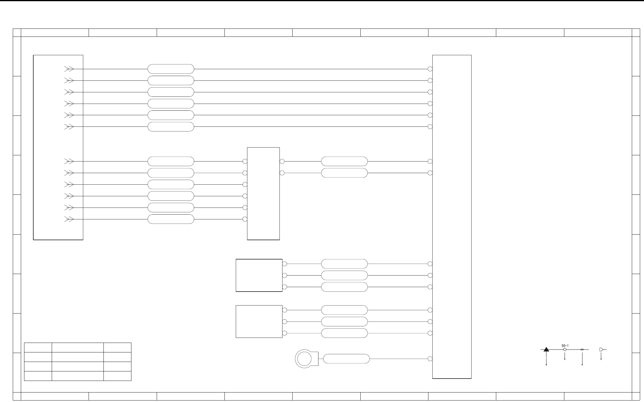
OVERALL WIRING DIAGRAM
4-99
6.5 RU-101 Overall Wiring Diagram
PS2
FUB
FS-113
MAIN BODY
PS1
Passage sensor
Front door sensor
CN1-1
CN1-2
CN4-1
CN4-2
CN1-3
CN200A-7
CN200A-6
CN200A-5
CN200C-3
CN200C-2
CN200B-6
CN200B-7
CN200B-4
CN200B-2
CN200B-5
CN200B-3
CN3-2
CN3-1
CN3-4
CN3-3
CN3-6
CN3-5
CN300-A9
CN300-A10
CN300-A7
CN300-A8
CN300-A5
CN300-A6
DC24V
DC24V
GND
DC24V
GND
GND
CN300-B10
CN300-B11
CN300-B6
CN300-B8
CN300-B3
CN300-B4
CN200A-4
CN200A-3
CN200A-2
CN200C-1
DC5V
PS2 ON
GND
DC24V
GND
GND
MTXD
MRXD
MRTS
MRTS
GND
DC5V
PS1 ON
GND
CN2-1
CN2-2
CN2-3
1
A
B
C
D
E
F
G
H
I
A
B
C
D
E
F
G
H
I
23456789
123456789
Symbol Part name Location
FUB Fuse board 4-C
PS1 Front door sensor 4-F
PS2 Passage sensor 4-G
Symbol
Crimp
Connetcor Faston
Relay connector

OVERALL WIRING DIAGRAM
4-100
Blank page
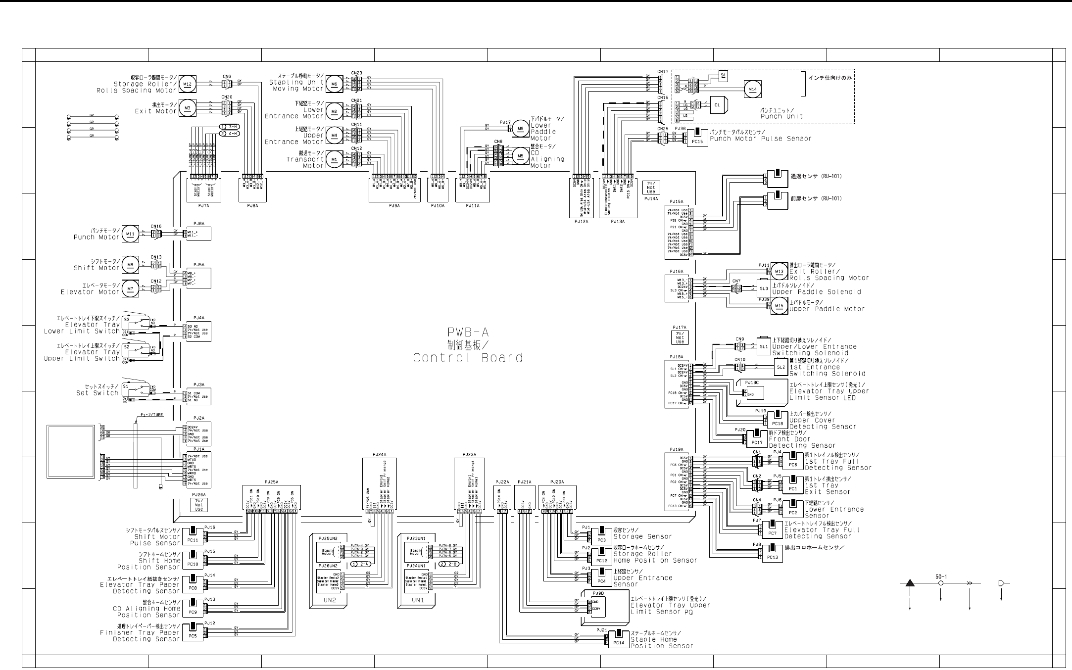
OVERALL WIRING DIAGRAM
4-101
6.6 FS-113 Overall Wiring Diagram
CN200C
CN201B
PS1
PS2
Exit Roll Home
Position Sensor
Passage Sensor (RU-101)
Front Door Sensor (RU-101)
PWB-C
PWB-D
RU-101
W
W
W
W
B
B
Hole Punch Position Switch
Hole Punch
Selector Motor
PWB-E_GL
PWB-E_GL
PWD-F
PWD-F_GL
PWD-F
PWD-F_GL
Only for inch
destination
1
A
B
C
D
E
F
G
H
I
A
B
C
D
E
F
G
H
I
23456789
123456789
Symbol
Crimp
Connetcor Faston
Relay connector

OVERALL WIRING DIAGRAM
4-102
Symbol Part name Location
RU-101 RU-101 1-F
M1 Transport motor 3-B
M2 Lower entrance motor 3-A
M3 Exit motor 2-A
M4 Upper entrance motor 3-B
M5 CD aligning motor 5-B
M6 Stapling unit moving sensor 3-A
M7 Elevator motor 1-D
M8 Shift motor 1-C
M9 Lower paddle motor 5-A
M11 Punch motor 1-C
M12 Storage roller/rolls spacing motor 2-A
M13 Exit roller/rolls spacing motor 7-D
M14 Hole punch selector motor 7-A
M15 Upper paddle motor 7-D
CL Punch clutch 6-A
SL1 Upper/Lower entrance switching solenoid 7-E
SL2 1st entrance switching solenoid 7-E
SL3 Upper paddle solenoid 7-D
S1 Set switch 1-E
S2 Elevator tray upper limit switch 1-E
S3 Elevator tray lower limit switch 1-D
S4 Hole punch position switch 7-A
PC1 1st tray exit sensor 7-G
PC2 Lower entrance sensor 7-G
PC3 Storage sensor 5-H
PC4 Upper entrance sensor 5-H
PC5 Finisher tray paper detecting sensor 2-I
PC6 1st tray full detecting sensor 7-F
PC7 Elevator tray full detecting sensor 7-H
PC8 Elevator tray paper detecting sensor 2-H
PC9 CD aligning home position sensor 2-I
PC10 Shift home position sensor 2-H
PC11 Shift motor pulse sensor 2-H
PC12 Storage roller home position sensor 5-H
PC13 Exit roll home position sensor 7-H
PC14 Staple home position sensor 6-I
PC15 Punch motor pulse sensor 6-B
PC17 Front door detecting sensor 7-F
PC18 Upper cover detecting sensor 7-F
PS1 Front door sensor (RU-101) 7-B
PS2 Passage sensor (RU-101) 7-B
PWB-C Elevator tray upper limit sensor LED 7-E
PWB-D Elevator tray upper limit sensor PQ 5-I
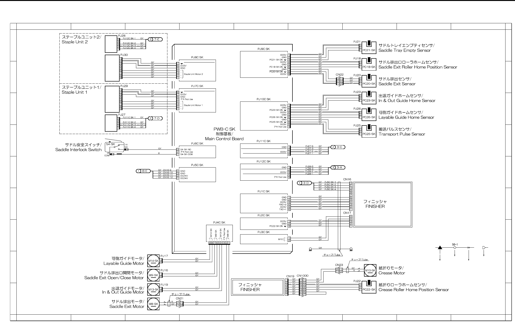
OVERALL WIRING DIAGRAM
4-103
6.7 SK-114 Overall Wiring Diagram
1
A
B
C
D
E
F
G
H
I
A
B
C
D
E
F
G
H
I
23456789
123456789
FS-114
FS-114
FS-114
FS-114
Saddle Stapler 2 Needle Empty Detect Sensor
Saddle Stapler 2 Self Priming Detect Sensor
Saddle Stapler 1 Needle Empty Detect Sensor
Staple Home Position Sensor 1
Staple Home Position Sensor 2
Saddle Stapler 1 Self Priming Detect Sensor
Symbol
Crimp
Connector Faston
Relay connector

OVERALL WIRING DIAGRAM
4-104
Symbol Part name Location
FS-114 FS-114 4-H, 7-E
M8-SK Saddle exit motor 3-I
M9-SK Saddle exit open/close motor 3-H
M10-SK Crease motor 7-G
M13-SK In & out guide motor 3-H
M14-SK Layable guide motor 3-G
PC18-SK Saddle exit roller home position sensor 7-A
PC20-SK Saddle exit sensor 7-B
PC21-SK Saddle tray empty sensor 7-A
PC22-SK Crease roller home position sensor 7-H
PC23-SK In & out guide home position sensor 7-B
PC25-SK Transport pulse sensor 7-C
PC26-SK Layable guide home sensor 7-C
S4-SK Saddle interlock switch 2-D
PWB-C SK Main control board 3-A
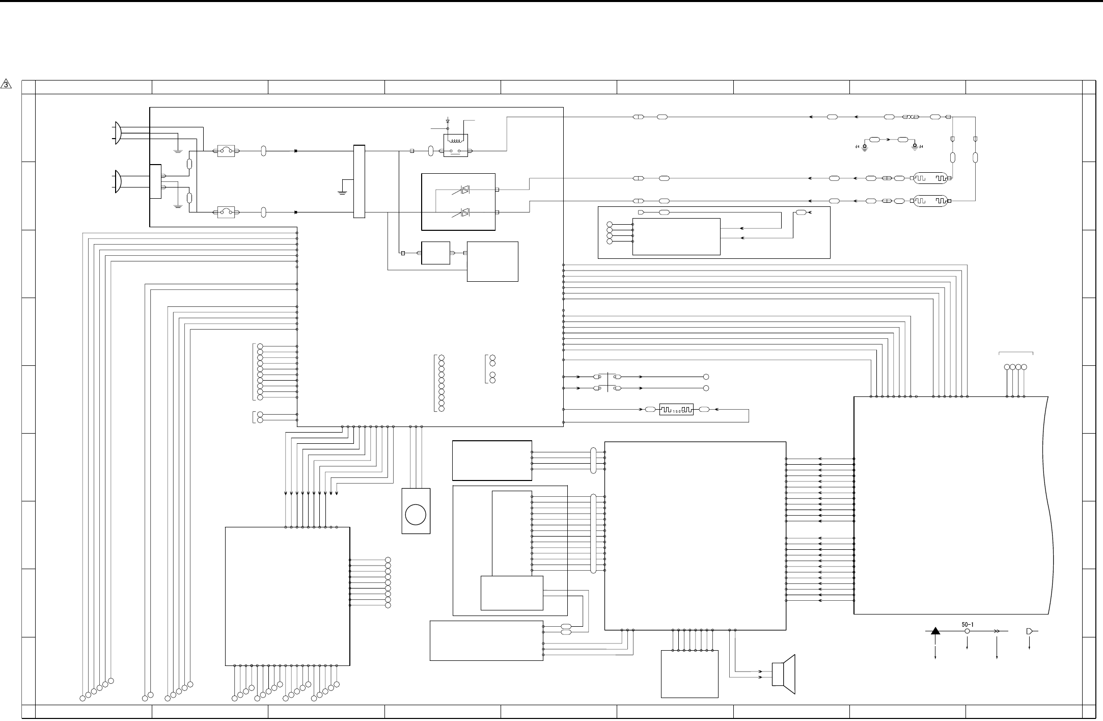
APPENDIX
Appendix-1
7. APPENDIX
7.1 7145 Overall Wiring Diagram (1/4)
1
A
B
C
D
E
F
G
H
I
A
B
C
D
E
F
G
H
I
23456789
123456789
AC(H)
FT3
FT4
FT5
FT6
BT1
NF
BT3
CBR 1
CBR 2
Circuit breaker/1
JAPAN AC100V 50/60Hz
EUROPE 200-240V 50Hz
USA 120V 60Hz
Circuit breaker/2
AC(N)
BT2
FT2
FT1
INLET
DCPS
PLUG
OB
SCB 1/3
PLUG
J:40LA8861
12V 42- 9
SGND 42- 8
-12V 42- 7
SGND 42- 6
12V 42- 5
SGND 42- 4
SGND 42- 3
5V 42- 2
5V 42- 1
-12V 31- 7
SGND 31- 6
12V 31- 5
NMI 31- 4
24V 31- 3
5VV 31- 2
N.C 31- 1
SGND 500- 4
SGND 500- 3
5V 500- 2
5V 500- 1
26 25 24 23
PTC
935-2935-1
PTC heater
24V 8-2
PGND 8-4
SWD24V
Interlock switch
SWD24V
31
30
SW3
J24-1A #250
J24-2A #250 J24-2B #250
J24-1B #250
24V 5-1
24V 5-2
J23-2
J23-1
J23-4
J23-3
Speaker
for DCPS
83- 1 X2
- 2 Y2
- 3 X1
- 4 Y1
PAKB
- 3 DIN
- 4 LP
- 9 D0
-10 D1
-11 D2
-12 D3
-13 VEE
86-14 VLCD
- 5 XSCL
- 1 DISPOFF
- 2 N.C
INV2
LCDB
BL
88- 3
- 2
- 1
89-1 FL HOT
-4 FL GND
84-3 5V
84-5 INV ON(PWM)
84-4 SGND
- 8 VEE(24V)
- 7 VSS(GND)
- 6 VDD(5V)
85 - 5
85 - 1
85 - 2
85 - 3
84-1 SGND
84-2 MONIT
84-9 SCAN6
84-10 RTN3
PSW2B
/SW2
85 - 4
84-6 VR L
84-8 VR H
85 - 8
85 - 7
85 - 6
84-7 VR SIG
84-12 SGND
84-13 SW2
84-11 5V
FCB
34-A8 SGND
34-A9 OPRTS
34-A10 OPRXD
34-B1 UD2
34-B7 OPRST
34-A3 UD1
34-A4 XSCL
34-B3 UD0
34-A1 UD3
34-A2 SGND
34-A5 SGND
34-A6 YD
34-A7 OPTXD
34-A11 SGND
34-A12 OPCTS
34-B2 SGND
34-B4 LP
34-B5 SGND
34-B6 LCDENB
34-B8 SGND
34-B9 OPINT
34-B10 MONIT
34-B11 5V
34-B12 5V
80-A12
80-A11
80-A10
80- A9
80- A8
80- A7
80- A5
80- A4
80- A3
80- A2
80- A1
80-B12
80-B11
80-B10
80- B9
80- B8
80- B7
80- B5
80- B4
80- B3
80- B2
80- B1
80- A6
80- B6
J38-A1 -A12
J38-A2 -A11
J38-A3 -A10
J38-A4 -A9
J38-A5 -A8
J38-A6 -A7
J38-A7 -A6
J38-A8 -A5
J38-A9 -A4
J38-A10 -A3
J38-A11 -A2
J38-A12 -A1
J38-B1 -B12
J38-B2 -B11
J38-B3 -B10
J38-B4 -B9
J38-B5 -B8
J38-B6 -B7
J38-B7 -B6
J38-B8 -B5
J38-B9 -B4
J38-B10 -B3
J38-B11 -B2
J38-B12 -B1
BT6
DC PSY
24V
5V
+12V
-12V
SW1
BT7
Main power switch
Noise filter
N.C 2-7
5V 2-6
24V 2-5
NMI 2-4
12V 2-3
SGND 2-2
-12V 2-1
12V 7-17
SGND 7-24
5V 7-9
5V 7-11
SGND 7-13
SGND 7-15
SGND 7-21
-12V 7-23
CN99-4 SGND
CN99-3 SGND
CN99-2 L3 CONT
BT2
BT1
CN99-1 5V
FT23
FT26
FT25
Thermostat
FT20 FT21
L2
TS
J13-1
RT3
RT4
CN9-1
CN9-2
J21-01
J21-02
FT28
FT27
L3
CN9-3
J21-03
FT24
FT22
J13-4
J13-3
J13-2
CN9-3
J21-03
J24: 2 - 2
J24: 1 - 1
Fixing heater
lamp/1
Fixing heater
lamp/2
24V(C)
FT7 FT8
RL1 POWER
RL1 CNT
MAIN RL
AC(H)
AC(H)
FT9 FT10
AC(N)
AC DRIVE
BT5
L2 DRIVE
L3 DRIVE
BT4
CR001
CR002
12V 7-19
6-2 24V
6-4 24V
6-6 24V
8-1 24V
1
2
3
4
5
6
7
8
9
10
11
12
for
BIAS
6-20 SGND
6-18 SGND
6-16 5V
6-14 5V
6-12 PGND
6-10 PGND
6-8 PGND
8-3 PGND
7-2 24V
7-4 PGND
7-12 5V
7-16 SGND
7-22 SGND
7-18 12V
7-20 SGND
for CB
50
51
52
53
for SCDB
DF-318
6-1 24V
6-3 24V
6-5 24V
13
14
15
16
17
18
19
20
21
22
6-7 PGND
6-9 PGND
6-11 PGND
6-13 5V
6-15 5V
6-17 SGND
6-19 SGND
for FNS
1-1 5V
1-2 5V
23
24
25
1-4 SGND
for OPTION
1-5 SGND
26
1-3 N.C
J60: 1 - 1
J60: 2 - 2
7-1 24V
7-5 24V
7-6 24V
J60: 3 - 3
J60: 4 - 4
J60: 7 - 7
J60: 8 - 8
J60: 9 - 9
J60:10 - 10
7-3 PGND
7-7 PGND
7-8 PGND
7-10 5V
7-14 SGND
- 6
- 5
7-25 RL PWR
7-26 RL PGND
36
37
38
39
40
32
33
34
35
DB-211
DB-411
FM1
DCPS cooling fan
10-1 DRIVE
10-2 EM
10-3 PGND
514: 1 - 2
514: 2 - 1
5-4 PGND
5-3 PGND
3-4 24V EM
3-5 FM1 EM
3-3 L3 CONT
3-2 L2 CONT
3-1 RL CONT
EUROPE Only
106- 1 24V2
106- 2 24V2
106- 3 24V2
106- 4 PGND
106- 7 LT CLOSE
106-10 M150 CONT
106-11 SD151 DRIVE
106-12 PS155
106-13 PS152
106-14 PS153
106-15 PS154
106-19 SGND
106-18 5V
106-17 LCT_TYPE
106-16 PS151
106- 9 M150 CLOCK
106- 8 M150 F/R
106- 6 M151 DRIVE
106- 5 PGND
77 78 79 80 81 82 83
71 72 73 74 75 76
98 99
100 101 102
93 94 95 96 97
88 89 90 91 92
84 85 86 87
Symbol
Crimp
Connector Faston
Relay connector
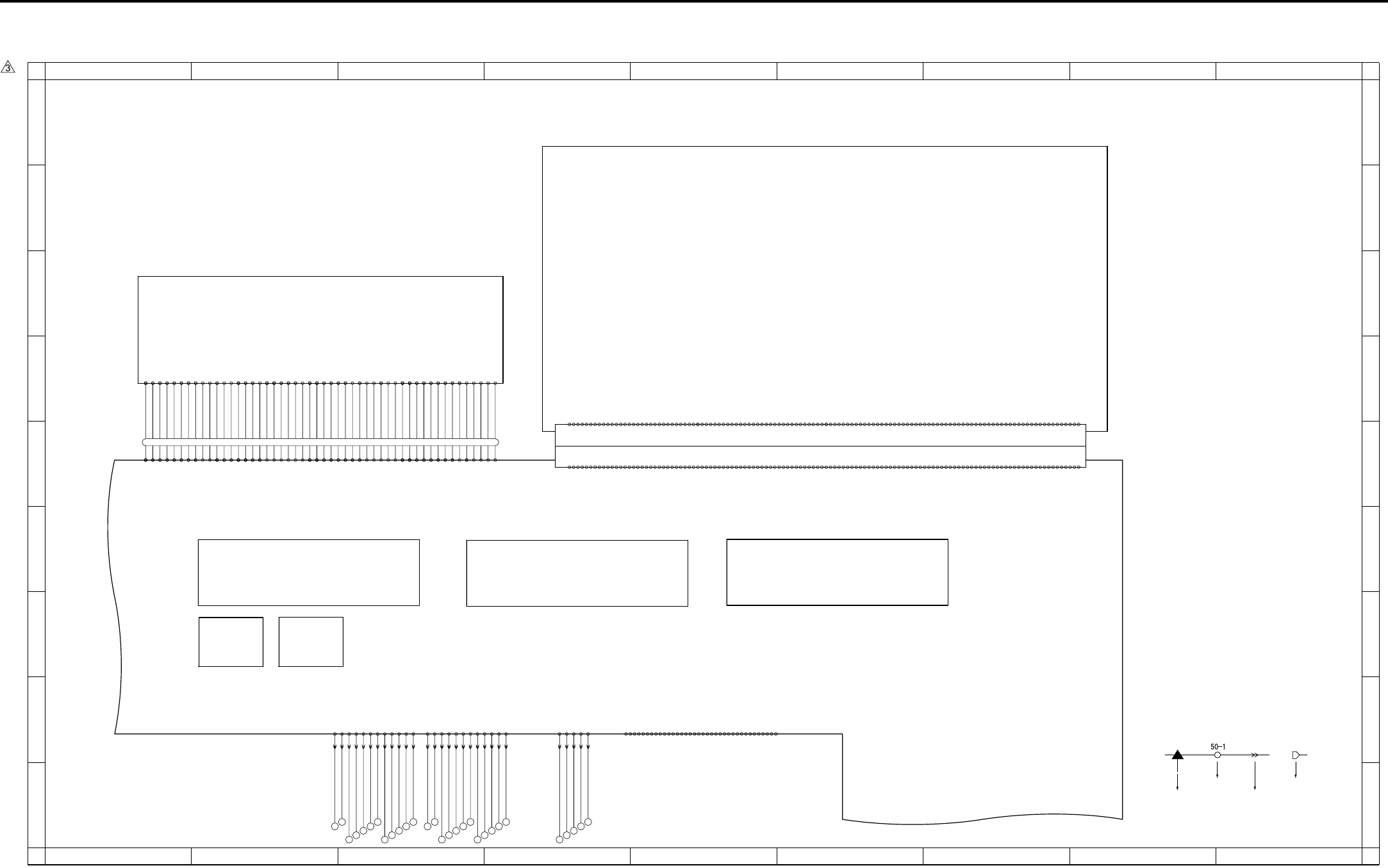
APPENDIX
Appendix-2
7.2 7145 Overall Wiring Diagram (2/4)
1
A
B
C
D
E
F
G
H
I
A
B
C
D
E
F
G
H
I
23456789
123456789
SCB 2/3
CN35
CN501 CN32,33
CN47
FANBattery
CN502
HD-103 Type A DIMM PRMB
-A11 DRAM_D24
-A13 DRAM_D22
-A16 DRAM_D19
-A17 DRAM_D18
-A18 DRAM_D17
-A24 DRAM_D12
-A25 DRAM_D11
-A27 DRAM_D9
-A44 XFAX_RST
-A 5 DRAM_D30
400-A 1 SGND
-A 6 DRAM_D29
-A19 DRAM_D16
-A28 DRAM_D8
-A33 DRAM_D3
-A35 DRAM_D1
-A36 DRAM_D0
-A50 XIOSEL2
CN37 Board to Board Connector
-B13 EXOUT_D6
-B16 EXOUT_D3
-B17 EXOUT_D2
-B18 EXOUT_D1
-B24 EXIN_D3
-B25 EXIN_D4
-B27 EXIN_D6
-B39 MONITOR
-B 1 SGND
-B 8 XAHA1_INT
-B 9 XEXIN_ACK
-B19 EXOUT_D0
-B28 EXIN_D7
-B40 XRC_INT
-B51 L_A1
-B56 L_A6
-A 3 SGND
-A 2 BCLOCK12
-A 4 DRAM_D31
-A 7 DRAM_D28
-A 8 DRAM_D27
-A 9 DRAM_D26
-A10 DRAM_D25
-A12 DRAM_D23
-A14 DRAM_D21
-A15 DRAM_D20
-A20 5V
-A21 DRAM_D15
-A22 DRAM_D14
-A23 DRAM_D13
-A26 DRAM_D10
-A29 DRAM_D7
-A30 DRAM_D6
-A31 DRAM_D5
-A32 DRAM_D4
-A34 DRAM_D2
-A37 5V
-A38 SGND
-A39 VBAT
-A40 XWAIT
-A41 5V
-A42 5V
-A43 DR_CKE
-A45 XIRST
-A46 XICS5
-A47 XICS7
-A48 XIRD
-A49 XMWR
-A51 L_A20
-A52 L_A19
-A53 L_A18
-A54 L_A17
-A55 L_A16
-A56 L_A15
-A57 L_A14
-A58 L_A13
-A59 L_A12
-A60 L_A11
-B 2 BCLOCK5
-B 3 SGND
-B 5 XFAX_COACK
-B 4 XFAX_CIACK
-B 6 XFAX_DIACK
-B 7 XFAX_DOACK
-B10 XEXOUT_ACK
-B11 -12V
-B12 EXOUT_D7
-B14 EXOUT_D5
-B15 EXOUT_D4
-B20 5V
-B21 EXIN_D0
-B22 EXIN_D1
-B23 EXIN_D2
-B26 EXIN_D5
-B29 XFAX_DRIVE
-B30 XEXOUT_REQ
-B31 XEXIN_REQ
-B32 XICS6
-B33 XFAX_DOREQ
-B34 XFAX_DIREQ
-B35 XFAX_COREQ
-B36 XFAX_CIREQ
-B37 5V
-B38 SGND
-B41 12V
-B42 PDA7
-B43 PDA6
-B44 PDA5
-B45 PDA4
-B46 PDA3
-B47 PDA2
-B48 PDA1
-B49 PDA0
-B50 L_A0
-B52 L_A2
-B53 L_A3
-B54 L_A4
-B55 L_A5
-B57 L_A7
-B58 L_A8
-B59 L_A9
-B60 L_A10
FK-102/FL-102
-13 SLCT
-15 N.C
-16 SGND
-17 SGND
-19 SGND
-20 SGND
-19 SGND
-22 SGND
-10 ACK
-11 BUSY
-28 SGND
-29 SGND
-31 INT
-33 SGND
-34 N.C
-35 N.C
-27 SGND
-23 SGND
-24 SGND
-25 SGND
-26 SGND
40- 1 STROBE
- 2 DATA0
- 3 DATA1
- 4 DATA2
- 5 DATA3
- 6 DATA4
- 7 DATA5
- 8 DATA6
- 9 DATA7
-12 PE
-32 FAULT
-14 AUTOFD
-18 N.C
-30 HLOGIC
-36 SELECTIN
432-B2 DACLK
432-B1 LOAD
432-B3 DI
432-B8 SGND
J53:B11 - B2
J53:B10 - B3
J53: B9 - B4
J53: B8 - B5
J53: B7 - B6
J53: B6 - B7
J53: B5 - B8
J53: B4 - B9
J53: B2 - B11
J53: B1 - B12
J53: A4 - A9
432-A5 SGND
432-A8 +5VRN
432-A10 -VIDEO2
432-A12 SGND
J53:A12 - A1
J53:A11 - A2
J53:A10 - A3
J53: A9 - A4
J53: A8 - A5
J53: A7 - A6
J53: A6 - A7
J53: A5 - A8
J53: A3 - A10
J53: A2 - A11
J53:B12 - B1
432-A1 /ENB1
J53: A1 - A12
J53: B3 - B10
432-A4 /S/H1
432-A2 /ALM1
432-A3 /BIAS
432-A6 LD+5V
432-A7 LD+5V
432-A9 SGND
432-A11 +VIDEO2
432-B4 SGND
432-B5 /ALM2
432-B6 /S/H2
432-B7 /ALM_RST
432-B9 SGND
432-B10 -VIDEO1
432-B11 +VIDEO1
432-B12 SGND
J52: 1 - 5
J52: 2 - 4
J52: 3 - 3
J52: 4 - 2
J52: 5 - 1
431- 4 SGND
431- 2 SGND
431- 1 /INDPR
431- 3 /INDEX
431- 5 5V
-39 APR
-48 12V
-43 5V
ADB
-31 +AD_D1
-14 SGND
-18 SGND
-20 SCLOCK
-12 +RCK
60- 1 SGND
- 3 CLAMP
- 5 BCLAMP
-13 -RCK
-15 SGND
-19 SCLOCK
-22 SDI
-23 SDO
-26 -AD_D0
-42 5V
-44 5V
-47 12V
-49 12V
46-37
46-38
46-39
46-41
46-42
46-31
46-27
46-14
46-15
46-16
46-18
46-19
46-20
46-22
46-23
46-21
46-17
46- 1
46- 2
46- 3
46- 5
46- 6
46- 7
46- 9
46-10
46-11
46-13
46-12
46- 8
46- 4
46-43
46-45
46-46
46-47
46-49
46-50
46-48
46-44
46-40
46-24
46-25
46-26
46-28
46-29
46-30
46-32
46-33
46-34
46-36
46-35
- 2 TG
- 4 ACLAMP
- 6 SGND
- 7 SGND
- 8 +TCK
- 9 -TCK
-10 SGND
-11 SGND
-16 +IN_CLOCK
-17 -IN_CLOCK
-21 *SEN
-24 SGND
-25 SGND
-27 +AD_D0
-28 SGND
-29 SGND
-30 -AD_D1
-32 SGND
-33 SGND
-34 -OUT_CLOCK
-35 +OUT_CLOCK
-36 SGND
-37 SGND
-38 ADRST
-40 SGND
-41 5V
-46 12V
-45 SGND
-50 SGND
127 128 129 130 131
122 123 124 125 126
115 116
117 118 119 120 121
110 111 112 113 114
103 104
105 106 107 108 109
Symbol
Crimp
Connector Faston
Relay connector
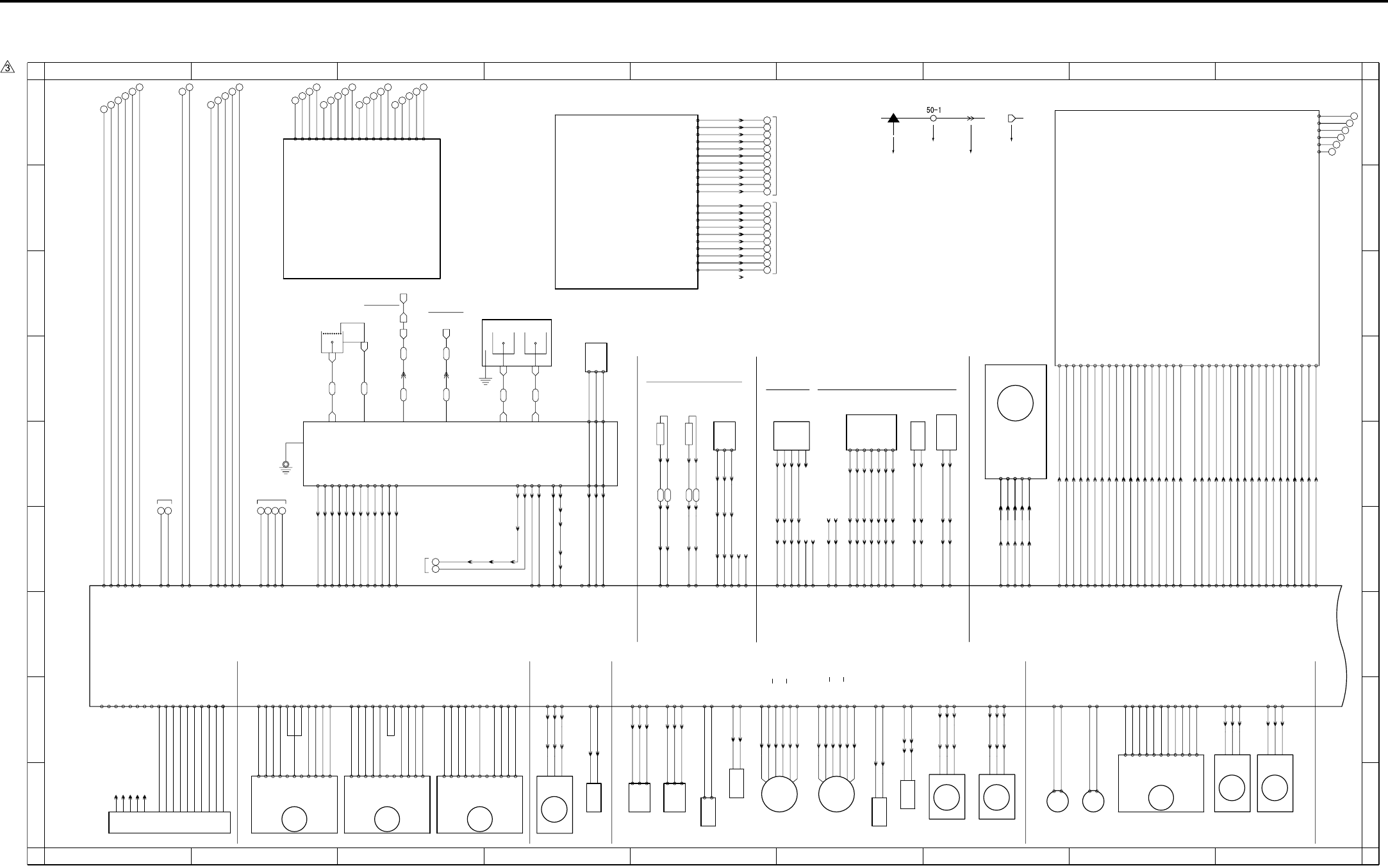
APPENDIX
Appendix-3
7.3 7145 Overall Wiring Diagram (3/4)
1
A
B
C
D
E
F
G
H
I
A
B
C
D
E
F
G
H
I
23456789
123456789
FUSING UNIT
Fixing
temperature
sensor/1
Fixing
temperature
sensor/2
951-1
PS 2
-3
-2
Fixing exit sensor
J13:A4 - A1
J13:A3 - A2
J13:A2 - A3
J13:A1 - A4
J12: 9 - 1
J12: 8 - 2
J12: 7 - 3
J12: 6 - 4
J13:B4 - B1
J13:B3 - B2
J13:B2 - B3
J12: 5 - 5
J12: 4 - 6
J12: 3 - 7
TH1 ANG 18- 6
SGND 18- 7
TH2 ANG 18- 8
SGND 18-10
PS 18-11
SGND 18- 9
980:1 - 1
980:2 - 2
980:3 - 3
980:4 - 4
J18: 1 - 3
J18: 2 - 2
J18: 3 - 1
N.C 18-14
N.C 18-13
J12: 2 - 8
J12: 1 - 9
5V 18-12
TH1 TH2
35-1
35-2
35-4
35-3
-10 PGND
COPY VENDER
35-5
-8 /CPF0
-9 /CPF1
-4 VEN.RXD
-3 VEN.CTS
-6 VEN.RTS
37-1 VEN.TXD
36-1 /M1
-2 /PF
-3 /PS0
-4 /PS1
-5 /PS2
-6 /PS3
-7 /SIDE
-2 PGND
-5 N.C
-7 PGND
-8 5V
FM2
J28: 3 - 1
J28: 2 - 2
J28: 1 - 3
911: 3 - 1
911: 2 - 2
911: 1 - 3
Fixing cooling fan
18- 4 LOCK
18- 5 PGND
18- 3 DRIVE
26-A16 SGND
M3
26-A17 5V
26-A11 N.C
26-A10 PGND
26-A9 PGND
26-A8 24V
26-A7 24V
26-A15 CONT
26-A14 CLOCK
26-A12 LD
26-A13 N.C
Developing motor
CB 1/2
24V 21- 6
PGND 21- 5
5V 21- 4
SGND 21- 3
SGND 21- 2
12V 21- 1
M1
23-A1 24V
23-A11 5V
23-A8 CLOCK
23-A9 CONT
23-A6 LOCK
23-A2 24V
Main motor
23-A10 SGND
23-A4 PGND
23-A3 PGND
23-A7 SGND
-3
29-B14 SGND
TLD
Toner level
sensor
984-1
-2
J05:3 - 1
J05:2 - 2
J05:1 - 3
29-B16 5V
29-B15 TLD ANG
Toner supply
motor/2
915:6 - 1
915:5 - 2
915:4 - 3
915:3 - 4
915:2 - 5
915:1 - 6
M10
29-A14 B
29-A13 B
29-A16 24V
29-A11 A
29-A12 A
29-A15 24V
954-1
-2
-3
29-B12 PS
Toner bottle
sensor
PS 5
J06:3 - 1
J06:2 - 2
J06:1 - 3
29-B13 5V
29-B11 SGND
904-1
-2
-3
M 5
Polygon motor
-4
-5
J51:1 - 5
J51:2 - 4
J51:3 - 3
J51:4 - 2
J51:5 - 1
CLOCK 22-5
LOCK 22-4
DRIVE 22-3
PGND 22-2
24V 22-1
J54:1 - 5
J54:2 - 4
J54:3 - 3
J54:4 - 2
J54:5 - 1
SD4
Cleaning web
solenoid
925:2 - 1
925:1 - 2
J29:2 - 1
J29:1 - 2
29-A7 DRIVE
29-A8 24V
SD5
926:2 - 1
1 - 2
ADU gate
solenoid
29-B8 24V
29-B7 DRIVE
-2
-1
92-7
-6
-5
-4
-3
Toner control
sensor board
Toner density sensor
5V 26-B7
J15: 5 - 9
J15: 6 - 8
J15: 7 - 7
J15: 8 - 6
J15: 9 - 5
J15:11 - 3
J15:10 - 4
J16-2
J16-3
J16-4
J16-5
J16-6
J16-7
J16-8 J11: 1 - 7
J11: 2 - 6
J11: 3 - 5
J11: 4 - 4
J11: 5 - 3
J11: 7 - 1
J11: 6 - 2
TNRIF 26-B10
TNOUT1 26-B11
TNOUT2 26-B12
SGND 26-B13
12V 26-B9
DRUM.TH 26-B8
PCL
Pre-
charging
lamp
J15: 2 - 12
J15: 1 - 13
DRIVE 26-B17
24V 26-B16
J16-12
J16-18
932:2 - 1
932:1 - 2
SD7
Separation
claw
solenoid
928:2 - 1
928:1 - 2
J15: 4 - 10
J15: 3 - 11
24V 26-B15
DRIVE 26-B14
J16-15
J16-16
983-1
-2
-4
J17-2
J17-3
-5
J17-5
J17-9 -3
TDS TCSB
CONT 25-A1
12V 25-A2
TDS ANG 25-A3
SGND 25-A4
J14: 5 - 2
J14: 6 - 1
J14: 4 - 3
J14: 3 - 4
N.C 25-A5
N.C 25-A6
J14: 2
J14: 1
J16-20
to BIAS
72- 5
CHARGER
Separation Transfer
GRID
HV
J16-11
72- 1
FT36 FT37
FT38 FT39
FT34
FT31 FT32 FT33
FT30
FT40
FT35
to GUIDE
PLATE
M8
907-1
-2
Tray
motor/L
26-B4 24V
26-B3 DRIVE
M7
Tray
motor/U
906-1
-2
26-B2 24V
26-B1 DRIVE
SGND 27- 6
HUM1 ANG 27- 7
5V 27- 8
J09-9
J09-8
J09-7 70- 3
70- 2
70- 1
73- 3
73- 2
73- 1
N.C 27- 5
910: 3 - 1
910: 2 - 2
910: 1 - 3
FM4
26-A2 EM
26-A3 PGND
26-A1 DRIVE
Internal cooling
fan/1
Registration clutch
MC1
920: 2 - 1
920: 1 - 2
29-A9 24V
29-A10 DRIVE
DF-318
24V
24V
5V
SGND
PGND
PGND
110-19
110-18
110-17
110-16
110-15
110-14
110-13
110-12
110-11
110- 9
110- 8
110- 7
110- 6
110- 5
110- 4
110- 3
110- 2
110- 1
110-10
300:A10- A10
300:A9 - A9
300:A8 - A8
300:A7 - A7
300:A6 - A6
300:A5 - A5
300:A4 - A4
300:A3 - A3
300:A2 - A2
300:A1 - A1
300:A11- A11
13
14
15
16
17
18
19
20
21
22
24V
24V
24V
PGND
PGND
PGND
5V
5V
SGND
SGND
for DCPS
61
62
63
64
65
66
67
68
69
70
SGND
FS SIN
SGND
SGND
60
FS CTS
SGND
N.C
FS RTS
N.C
SGND
FS SOUT
300:B11- B11
300:B10- B10
300:B9 - B9
300:B8 - B8
300:B7 - B7
300:B6 - B6
300:B5 - B5
300:B4 - B4
300:B3 - B3
300:B2 - B2
300:B1 - B1
for ENGINE
FS-112
FS-113
FS-114
N.C 26-B5
N.C 26-B6
J15:12 - 2
J15:13 - 1 J16-13
J16-14
70- 7
24V
PGND
70- 9
70- 8
B.SIG 27- 2
B.CONT 27- 1
for
DCPS
24V 27- 4
PGND 27- 3
70- 5
70- 4
70- 6
12
11
J25-4
J17-8 J17-11J25-2
J09-6
J09-5
J09-4
J09-3
J09-2
J09-1
J17-12J17-7
J25-5J25-1
SDC.SIG 15-A2
S.FB 15-A1
71- 1
71- 2
71- 3
71- 4
71- 7
71- 9
71-10
71-11
71-12
71- 8
71- 6
71- 5
J10:12 - 1
J10:11 - 2
J10:10 - 3
J10: 9 - 4
J10: 8 - 5
J10: 7 - 6
J10: 6 - 7
J10: 5 - 8
J10: 4 - 9
J10: 3 - 10
J10: 2 - 11
J10: 1 - 12
SAC.SIG 15-A3
S.CONT 15-A4
T.FB 15-A5
T.SIG 15-A6
T.CONT 15-A7
G.CONT 15-A8
C.FB 15-A9
GRID.SIG 15-A10
CHG.SIG 15-A11
C.CONT 15-A12
M9
23-B11 24V
23-B1 5V
23-B3 CONT
23-B10 24V
23-B4 CLOCK
23-B5 F/R
Paper feed motor
M11
Fixing motor
41-1 24V
41-2 24V
41-8 CLOCK
41-9 CONT
41-11 5V
41-6 LOCK
S.G -2
CONT -3
CLK -4
LD -6
H/L -7
P.G -8
P.G -9
24V -11
CW/CCW-5
24V -10
5V -1
S.G -2
CONT -3
CLK -4
LD -6
H/L -7
P.G -8
P.G -9
24V -11
CW/CCW-5
24V -10
5V -1
S.G -2
CONT -3
CLK -4
LD -6
H/L -7
P.G -8
P.G -9
24V -11
CW/CCW-5
24V -10
5V -1
41-7 N.C
41-5 N.C
23-B2 SGND
23-B6 SGND
23-B8 PGND
23-B9 PGND
41-10 SGND
41-4 PGND
41-3 PGND
5V -1
S.G -2
CONT -3
CLK -4
CW/CCW-5
LD -6
H/L -7
P.G -8
P.G -9
24V -10
24V -11
DEV UNIT DRUM CARTRIGE
FM3
912: 3 - 1
912: 2 - 2
912: 1 - 3
Internal
dehumidifying
fan/1
29-A2 EM
J38: 3 - 4
J38: 2 - 5
29-A1 DRIVE
29-A3 PGND
J38: 1 - 6
Toner supply
motor/1
M4
903:6 - 1
903:5 - 2
903:4 - 3
903:3 - 4
903:2 - 5
903:1 - 6
29-B1 A
29-B6 24V
29-B2 A
29-B5 24V
29-B3 B
29-B4 B
913: 3 - 1
913: 2 - 2
913: 1 - 3
FM5
Developing
suction fan
26-A5 EM
26-A6 PGND
26-A4 DRIVE
914: 3 - 1
914: 2 - 2
914: 1 - 3
Internal
dehumidifying
fan/2
FM6
29-A5 EM
J38: 6 - 1
J38: 5 - 2
J38: 4 - 3
29-A6 PGND
29-A4 DRIVE
68-A9
68-A7
68-A10
M301 F/R 17-A3
M301 EM 17-A4
M301 RST 17-A5
M301 RTN 17-A6
SD301 DRIVE 17-A8
SGND 17-A7
PS301 17-A9
PS304 17-A12
PS305 17-A13
SD302 DRIVE 17-B9
PS306 17-B6
PS308 17-B7
PS309 17-B8
M303 F/R 17-B13
M303 EM 17-B14
M301 CLOCK 17-A1
SGND 17-A2
PS302 17-A10
PS303 17-A11
M303 V0 17-B4
M303 V1 17-B5
M302 V0 17-B2
M302 V1 17-B3
68-A6
68-A11
68-A12
68-A13
68-A14
68-A15
68-A16
68-A17
68-A18
68-B16
68-B17
M301 V0 17-B1
VR301 17-A14 68-A5
201:A5 - A14
201:A6 - A13
201:A7 - A12
201:A8 - A11
201:A18- A1
201:A17- A2
201:A16- A3
201:A15- A4
201:A14- A5
201:A13- A6
201:A12- A7
201:A11- A8
201:A10- A9
201:A9 - A10
201:B5 - B14
201:B6 - B13
201:B7 - B12
201:B8 - B11
201:B10- B9
201:B9 - B10
201:B11- B8
201:B12- B7
201:B13- B6
201:B14- B5
201:B15- B4
201:B16- B3
201:B17- B2
201:B18- B1
M302 EM 17-B15
SGND 17-B16
M302 CLOCK 17-B17 68-B2
68-B3
68-B4
201:B2 - B17
201:B3 - B16
201:B4 - B15
68-A4
SD303 CONT 17-A15
FM301 CONT 17-A16
FM301 EM 17-A17
201:A2 - A17
201:A3 - A16
201:A4 - A15
SGND 17-B10
M303 CLOCK 17-B11
SGND 17-B12
68-A2
68-A3
68-B5
68-B6
68-B7
68-B8
68-B9
68-B10
68-B11
68-B12
68-B13
68-B15
68-B18
SGND 17-B18
201:B1 - B18
201:A1 - A18
5V 17-A18 68-A1
68-B1
68-B14
68-A8
Humidity sensor
982-1
-2
-3
HUM1
SD9
929:2 - 1
929:1 - 2
18- 2 24V
18- 1 DRIVE
Toner
solenoid
986-2
986-1
TC
Total counter
29-B9 24V
29-B10 DRIVE
24V 20- 1
24V 20- 2
PGND 20- 3
PGND 20- 4
3130
for SW3 EUROPE only
for FCB
50 51 52 53
FM1 EM 25-A7
24V EM 25-A8
L3 CONT 25-A9
L2 CONT 25-A10
RL CONT 25-A11
L3 CONT 40- 3
SGND 40- 1
SGND 40- 2
5V 40- 4
LT-203
77 78
79 80 81 82 83
71 72 73 74 75 76
84 85 86 87
98 99
100 101 102
93 94 95 96 97
88 89 90 91 92
132
133
134
135
136
137
Symbol
Crimp
Connector Faston
Relay connector
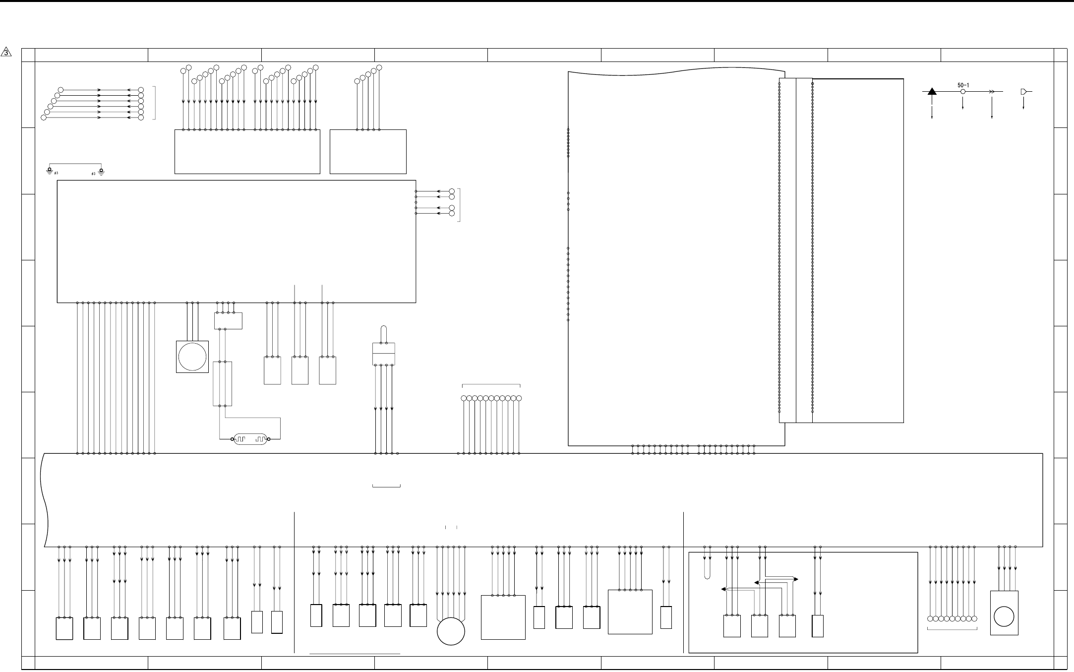
APPENDIX
Appendix-4
7.4 7145 Overall Wiring Diagram (4/4)
1
A
B
C
D
E
F
G
H
I
A
B
C
D
E
F
G
H
I
23456789
123456789
TSL
Transfer
synchro-
nization
lamp
933:2 - 1
1 - 2
J02: 2 - 6
J02: 1 - 7
24-A15 DRIVE
24-A15 SGND
CB 2/2
SCB 3/3
USB
LAN
- 3 TXD
39- 1 DCD
- 2 RXD
- 4 DTR
- 5 GND
- 6 DSR
- 7 RTS
- 8 CTS
KRDS I/F
- 9 RI
BYPASS TRAY
966-3
-2
-1
PS17
APS sensor
64-2 PS
64-1 5V
64-3 SGND
64-4 SGND
64-6 5V
964-3
-2
-1
PS15
APS timing
sensor
64-5 PS
64-7 SGND
64-9 5V
963-3
-2
-1
Scanner home
position sensor
PS14
64-8 PS
M2
-2 V
Scanner motor
62-1 U
-3 W
931-4
-3
930-1 L.V.
-3 H.V.
Exposure lamp
INV1
L1
63-1 24V
-1
63-2 L1 CONT
63-3 L1 EM
63-4 PGND
96-1
96-3
97-3
97-1
-2
PGND 60- 2
N.C 60- 3
5V 60- 4
SGND 60- 5
J20: 2 - 9
J20: 4 - 7
J20: 7 - 4 4
7
9
1
for DCPS
24V 60- 1
2
3
5
6
8
10
for DCPS
J20:10 - 1
SD2
1st paper
feed
solenoid/L
923: 2 - 1
923: 1 - 2
25-A14 24V
25-A15 DRIVE
959-1
-3
-2
Upper limit
sensor/L
J03:11 - 1
J03:10 - 2
J03: 9 - 3
PS 10
24-A13 5V
24-A11 SGND
(J03:CT)
24-A12 PS
960-1
-3
-2
No paper
sensor/U
J03: 8 - 4
J03: 7 - 5
J03: 6 - 6
PS 11
24-A10 5V
24-A8 SGND
24-A9 PS
Tray set
sensor/L
961-1
-2
-3
PS 12
25-B15 5V
25-B13 SGND
J32:3 - 1
J32:2 - 2
J32:1 - 3
25-B14 PS
956-1
-3
-2
Upper limit
sensor
J01: 3 - 7
J01: 2 - 8
J01: 1 - 9
25-B5 PS
PS 7
25-B6 5V
25-B4 SGND
957-1
-3
-2
No paper
sensor
J01: 6 - 4
J01: 5 - 5
J01: 4 - 6
25-B8 PS
PS 8
25-B7 SGND
25-B9 5V
Tray set
sensor/U
958-1
-2
-3
25-B17 PS
PS 9
25-B16 SGND
25-B18 5V
J31:3 - 1
J31:2 - 2
J31:1 - 3
25-B11 PS
Registration
sensor
J01:9 - 1
J01:8 - 2
J01:7 - 3
25-B12 5V
25-B10 SGND
950-1
-2
-3
PS 1
J33:3 - 1
J33:2 - 2
J33:1 - 3
910: 4 - 1
910: 3 - 2
910: 2 - 3
FM7
Internal cooling fan/2
910: 1 - 4
39-1 DRIVE
39-2 EM
39-4 SGND
39-3 H/L
MC2
Loop clutch
921: 2 - 1
921: 1 - 2
24-A1 24V
24-A2 DRIVE
SD3
By-pass
paper feed
solenoid
24-B20 24V
924: 2 - 1
924: 1 - 2
J04:11 - 1
J04:10 - 2
24-B19 DRIVE
By-pass
no paper
sensor
24-B11 PS
J04: 3 - 9
PS13
962-1
-2
-3
24-B12 5V
24-B10 SGND
J04: 2 - 10
J04: 1 - 11
M6
905: 6 - 1
905: 5 - 2
905: 4 - 3
905: 3 - 4
905: 2 - 5
905: 1 - 6
24-B1 A
24-B6 24V
24-B2 A
24-B5 24V
24-B3 B
24-B4 B
ADU motor
24-B8 PS
ADU sensor
-3
-2
953-1
PS 4
24-B9 5V
24-B7 SGND
J30:3 - 1
J30:2 - 2
J30:1 - 3
RT3
RT3
200: 1 - 1
200: 2 - 2
200: 3 - 3
200: 4 - 4
200: 5 - 5
200: 6 - 6 20: 9 - 2
20: 8 - 3
20: 6 - 5
20: 5 - 6
20: 3 - 8
20: 1 - 10
50-B12
-B11
-B10
- B9
- B8
- B7
- B6
- B4
- B3
- B2
- B5
J50: B1 - B12
J50: B2 - B11
J50: B4 - B9
J50: B5 - B8
J50: B6 - B7
J50: B7 - B6
J50: B8 - B5
J50: B9 - B4
J50:B10 - B3
J50:B11 - B2
LDB
-A11
-A10
- A9
- A8
- A7
- A6
- A5
- A3
- A2
- A1
- A4
J50: A4 - A9
J50:A12 - A1
J50:A11 - A2
J50:A10 - A3
J50: A9 - A4
J50: A8 - A5
J50: A7 - A6
J50: A6 - A7
J50: A5 - A8
J50: A3 - A10
J50: A2 - A11
- B1 J50:B12 - B1
50-A12 J50: A1 - A12
J50: B3 - B10
45-1 VDD
45-4 SGND
45-2 -Data
45-3 +Data
41-1 TX+
41-2 TX-
41-3 RX+
41-4 N.C
41-5 N.C
41-6 RX-
41-7 N.C
41-8 N.C
41-9 FG
41-11 VDD1
41-10 FG
41-11 LED1
41-11 VDD2
41-11 LED2
-2
-3
-4
-5
51-1
INDEX
(CN51
44-A3
44-A4
44-A8
44-A11
44-A1
44-A2
44-A5
44-A6
44-A7
44-A9
44-A10
44-B1
B VV 28-A1
TONYY 28-A2
P VV 28-A3
S VV 28-A4
SGND 28-A6
EE VV 28-A5
EG TRS 28-A7
EG TXD 28-A8
EG CTS 28-A9
EG RXD 28-A10
SGND 28-A11
DDF VV 28-B11
N.C 28-B10
EG INT 28-B5
EG RST 28-B4
PS301 28-B6
APS TIM 28-B7
44-B4
44-B7
44-B8
SGND 28-B1
5V SYS 28-B2
SGND 28-B3 44-B9
44-B11
FIX OK 28-B9
SGND 28-B8
44-B10
44-B6
44-B5
44-B3
44-B2
SCDB
-B33 PCI_C_BE0
-B12 PCI_AD29
-B16 PCI_C_BE3
-B20 PCI_AD18
-B26 PCI_C_BE1
-B31 PCI_AD8
-A20 PCI_AD17
-A21 PCI_C_BE2
-A26 PCI_AD15
38-B 1 XFAN
-B 2 FANHI
-B 9 XPCI_REQ0
-B19 PCI_AD20
CN38 Board to Board Connector(100pin)
-A24 XPCI_DEVSEL
38-A 1 XFAN_LK
-A 2 SGND
-A 4 SGND
-A 6 SGND
-A 7 SGND
-A 8 SGND
-A13 SGND
-A18 SGND
-A27 SGND
-A32 SGND
-A37 SGND
-A38 SGND
-A44 SGND
-A46 SGND
-A48 SGND
-A49 SGND
-A14 26/ISEL6
-A19 PCI_AD19
-A22 PCI_IRDY
-A23 SGND
-A25 PAR
-A28 PCI_AD13
-A29 PCI_AD11
-A30 PCI_AD9
-A31 PCI_AD7
-A33 PCI_AD6
-A34 PCI_AD4
-A35 PCI_AD2
-A36 PCI_AD0
-A39 5V
-A40 5V
-A41 5V
-A42 5V
-A43 5V
-A45 -12V
-A47 12V
-A50 12V
-B 4 SGND
-B 5 SGND
-B 6 SGND
-B 8 SGND
-B13 SGND
-B18 SGND
-B23 SGND
-B27 SGND
-B32 SGND
-B37 SGND
-B38 SGND
-B44 SGND
-B46 SGND
-B48 SGND
-B49 SGND
-B 7 BCLOCK3
-B11 PCI_AD31
-B14 PCI_AD27
-B15 PCI_AD25
-B17 PCI_AD22
-B21 PCI_AD16
-B22 XPCI_FRAME
-B24 XPCI_TRDY
-B25 XPCI_STOP
-B28 PCI_AD14
-B29 PCI_AD12
-B30 PCI_AD10
-B34 PCI_AD5
-B35 PCI_AD3
-B36 PCI_AD1
-B39 5V
-B40 5V
-B41 5V
-B42 5V
-B43 5V
-B45 -12V
-B47 12V
-B50 12V
-A 3 NC
-A 5 /RST
-A 9 /GNT2
-A10 NC
-A11 PCI_AD30
-A12 PCI_AD28
-A15 PCI_AD24
-A16 PCI_AD23
-A17 PCI_AD21
-B 3 N.C
-B10 N.C
for DB UNIT
J61 : 1 - 9
J61 : 2 - 8
J61 : 3 - 7
J61 : 4 - 6
J61 : 5 - 5
J61 : 6 - 4
J61 : 7 - 3
J61 : 8 - 2
J61 : 9 - 1
32 33 34 35 36 37 38 39 40
19- 1 DB_RTS
19- 4 DB_CTS
19- 2 SGND
19- 3 DB_RXD
19- 5 SGND
19- 6 DB_TXD
19- 7 DB_EXIT
19- 8 LCT_EXIT
19- 9 DB_RST
L1INVB
24-B17 PS
J04: 9 - 3
J04: 8 - 4
J04: 7 - 5
PS20
969-1
-2
-3
24-B18 5V
24-B16 SGND
By-pass
tray paper
size sensor
J08: 6 - 1
J08: 5 - 2
J08: 4 - 3
J04: 6 - 6
J04: 5 - 7
J04: 4 - 8
VR1
98 -3
-2
-1
By-pass
tray paper
size VR
24-B15 SGND
24-B13 5V
J08: 3 - 4
J08: 2 - 5
J08: 1 - 6
24-B14 VR
25-A17 PS
J41:1 - 3
J41:2 - 2
J41:3 - 1
25-A16 5V
25-A18 SGND
971-1
-2
-3
PS22
Timing
sensor/L
25-B2 PS
J40:1 - 3
J40:2 - 2
J40:3 - 1
25-B1 5V
25-B3 SGND
970-1
-2
-3
PS21
Timing
sensor/U
IP-432
DRIVE 35- 4
SGND 35- 5
SGND 35- 3
SIG 35- 2
24V 35- 1
985A-3
-1
-2
-4
CN985A
CN985B
985B-1
985B-2
Key counter
KC
(Option)
J26: 2 - 3
J26: 4 - 1
J26: 1 - 4
J26: 3 - 2
For Finisher
J42:2 - 2
J42:3 - 3
972-1
-2
-3
PS23
IT exit
sensor/U
J42:5 - 5
J42:6 - 6
974-1
-2
-3
PS25
IT door
sensor
38- 1 PS
38- 2 SGND
38- 8 SGND
J42:10- 10
J42:11- 11
J42:4 - 4
38- 3 5V
(CE1)
(CE1)
973-1
-2
-3
PS24
IT exit
sensor/L
(CE1)
38- 5 SGND
IT-101
SD8
939: 1 - 2
939: 2 - 1
J42:8 - 8
J42:9 - 9
Gate solenoid
38- 6 24V
38- 9 IT.SET
38- 4 PS
38- 7 DRIVE
1st paper
feed
solenoid/U
SD1
922: 2 - 1
922: 1 - 2
25-A13 24V
25-A12 DRIVE
SGND 16-10
5V 16-11
PS17 16-12
PS15 16-13
PS14 16-14
M2 DRIVE 16- 5
M2 EM2 16- 4
M2 V0 16- 6
M2 V1 16- 7
61-11
61-12
M2 CLOCK 16- 1
SGND 16- 2
M2 EM1 16- 3
L1 CONT 16- 8
L1 EM 16- 9
61- 4
61- 7
61- 8
61- 9
61-10
61-13
61-14
61-15
61- 6
61- 5
61- 3
61- 2
5V 16-15 61- 1
FS TXD 15-B1
SGND 15-B2
FS RTS 15-B4
FS RXD 15-B6
SGND 15-B5
SGND 15-B8
FS CTS 15-B9
70 69 68 67 66 65 64 63 62 61 60
SGND 15-B10
SGND 15-B11
N.C 15-B12
N.C 15-B3
N.C 15-B7
90-1
-2
-4
-3
-5
PFDB/U
J02: 7 - 1
J02: 6 - 2
J02: 5 - 3
24-A16 SIZE.UP.D
24-A17 SIZE.UP.C
24-A18 SIZE.UP.B
24-A19 SIZE.UP.A
J02: 3 - 5
J02: 4 - 4
24-A20 SGND
91-1
-2
-4
-3
-5
PFDB/L
J03: 5 - 7
J03: 4 - 8
J03: 3 - 9
J03: 2 - 10
J03: 1 - 11
24-A6 SIZE.LOW.A
24-A5 SIZE.LOW.B
24-A4 SIZE.LOW.C
24-A3 SIZE.LOW.D
24-A7 SGND
for KC
132
133
134
135
136
137
127 128 129 130 131
122 123 124 125 126
115 116
117 118 119 120 121
110 111 112 113 114
103 104
105 106 107 108 109
Symbol
Crimp
Connector Faston
Relay connector

APPENDIX
Appendix-5
Symbol Part name Location Symbol Part name Location Symbol Part name Location
COPY VENDER COPY VENDER Appendix-3 1-I M2 Scanner motor Appendix-4 2-E PS24 IT exit sensor /L Appendix-4 7-I
DB-211 DB-211 Appendix-1 2-G M3 Developing motor Appendix-3 8-I PS25 IT door sensor Appendix-4 7-I
DB-411 DB-411 Appendix-1 2-G M4 Toner supply motor /1 Appendix-3 5-I TH1 Fixing temperature sensor /1 Appendix-3 5-E
DIMM DIMM Appendix-2 3-F M5 Polygon motor Appendix-3 7-D TH2 Fixing temperature sensor /2 Appendix-3 5-E
FK-102/FL-102 FK-102/FL-102 Appendix-2 4-A M6 ADU motor Appendix-4 4-I HUM1 Humidity sensor Appendix-3 4-D
FS-112 FS-112 Appendix-3 4-A M7 Tray motor /U Appendix-3 8-I TDS Toner density sensor Appendix-3 5-E
FS-113 FS-113 Appendix-3 4-A M8 Tray motor /L Appendix-3 7-I TLD Toner level sensor Appendix-3 5-I
HD-103 Type A HD-105 Appendix-2 2-F M9 Paper feed motor Appendix-3 3-I TS Thermostat Appendix-1 8-A
IP-432 IP-432 Appendix-4 7-A M10 Toner supply motor /2 Appendix-3 6-I SW1 Main power switch Appendix-1 4-C
IT-101 IT-101 Appendix-4 6-H M11 Fixing motor Appendix-3 3-I SW2 Sub power switch Appendix-1 6-I
KC Key counter Appendix-4 3-E FM1 DCPS cooling fan Appendix-1 4-F SW3 Interlock switch Appendix-1 5-E
LT-203 LT-203 Appendix-3 2-A FM2 Fixing cooling fan Appendix-3 4-I VR1 By-pass tray paper size VR Appendix-4 3-I
TC Total counter Appendix-3 5-I FM3 Internal dehumidifying fan /1 Appendix-3 7-I PTC PTC heater Appendix-1 6-E
DF-318 DF-318 Appendix-3 7-A FM4 Internal cooling fan /1 Appendix-3 9-I BATTERY Battery Appendix-2 2-G
ADB A/D conversion board Appendix-2 1-C FM5 Developing suction fan Appendix-3 9-I
CB Main control board Appendix-3 1-F FM6 Internal dehumidifying fan /2 Appendix-3 7-I
FCB Fixing control board Appendix-1 6-B FM7 Internal cooling fan /2 Appendix-4 9-I
INDEX Index sensor board Appendix-4 3-B MC1 Registration clutch Appendix-3 6-I
L1INVB Exposure lamp power supply board Appendix-4 2-E MC2 Loop clutch Appendix-4 6-I
LCDB Display board Appendix-1 4-F SD1 1st paper feed solenoid /U Appendix-4 3-I
LDB LD drive board Appendix-4 2-B SD2 1st paper feed solenoid /L Appendix-4 2-I
OB Operation board Appendix-1 5-F SD3 By-pass paper feed solenoid Appendix-4 3-I
PAKB Panel key board Appendix-1 4-F SD4 Cleaning web solenoid Appendix-3 6-I
PFDB/L Paper feed detection board /L Appendix-4 5-I SD5 ADU gate solenoid Appendix-3 5-I
PFDB/U Paper feed detection board /U Appendix-4 4-I SD7 Separation claw solenoid Appendix-3 6-E
PRMB Parameter memory board Appendix-2 5-F SD8 Gate solenoid Appendix-4 7-I
PSW2B Power SW2 board Appendix-1 6-I SD9 Toner solenoid Appendix-3 4-I
SCB System control board Appendix-1 8-E PS1 Registration sensor Appendix-4 1-I
SCDB Scanner drive board Appendix-4 1-B PS2 Fixing exit sensor Appendix-3 5-E
TCSB Toner control sensor board Appendix-3 6-D PS4 ADU sensor Appendix-4 4-I
DCPS DC power supply unit Appendix-1 1-A PS5 Toner bottle sensor Appendix-3 5-I
HV High voltage unit Appendix-3 2-E PS7 Upper limit sensor /U Appendix-4 2-I
INV1 Exposure lamp inverter Appendix-4 2-D PS8 No paper sensor /U Appendix-4 1-I
INV2 Display inverter Appendix-1 4-H PS9 Tray set sensor /U Appendix-4 1-I
CBR1 Circuit breaker /1 Appendix-1 2-A PS10 Upper limit sensor /L Appendix-4 5-I
CBR2 Circuit breaker /2 Appendix-1 2-B PS11 No paper sensor /L Appendix-4 5-I
NF Noise filter Appendix-1 3-A PS12 Tray set sensor /L Appendix-4 1-I
L1 Exposure lamp Appendix-4 2-F PS13 By-pass no paper sensor Appendix-4 4-I
L2 Fixing heater lamp /1 Appendix-1 8-B PS14 Scanner home position sensor Appendix-4 3-E
L3 Fixing heater lamp /2 Appendix-1 8-B PS15 APS timing sensor Appendix-4 3-E
PCL Pre-charging lamp Appendix-3 7-D PS17 APS sensor Appendix-4 3-E
TSL Transfer synchronization lamp Appendix-4 5-I PS20 By-pass tray paper size sensor Appendix-4 3-I
LCD LCD Appendix-1 4-F PS21 Timing sensor /U Appendix-4 2-I
BL Back light Appendix-1 4-H PS22 Timing sensor /L Appendix-4 2-I
M1 Main motor Appendix-3 2-I PS23 IT exit sensor /U Appendix-4 7-I
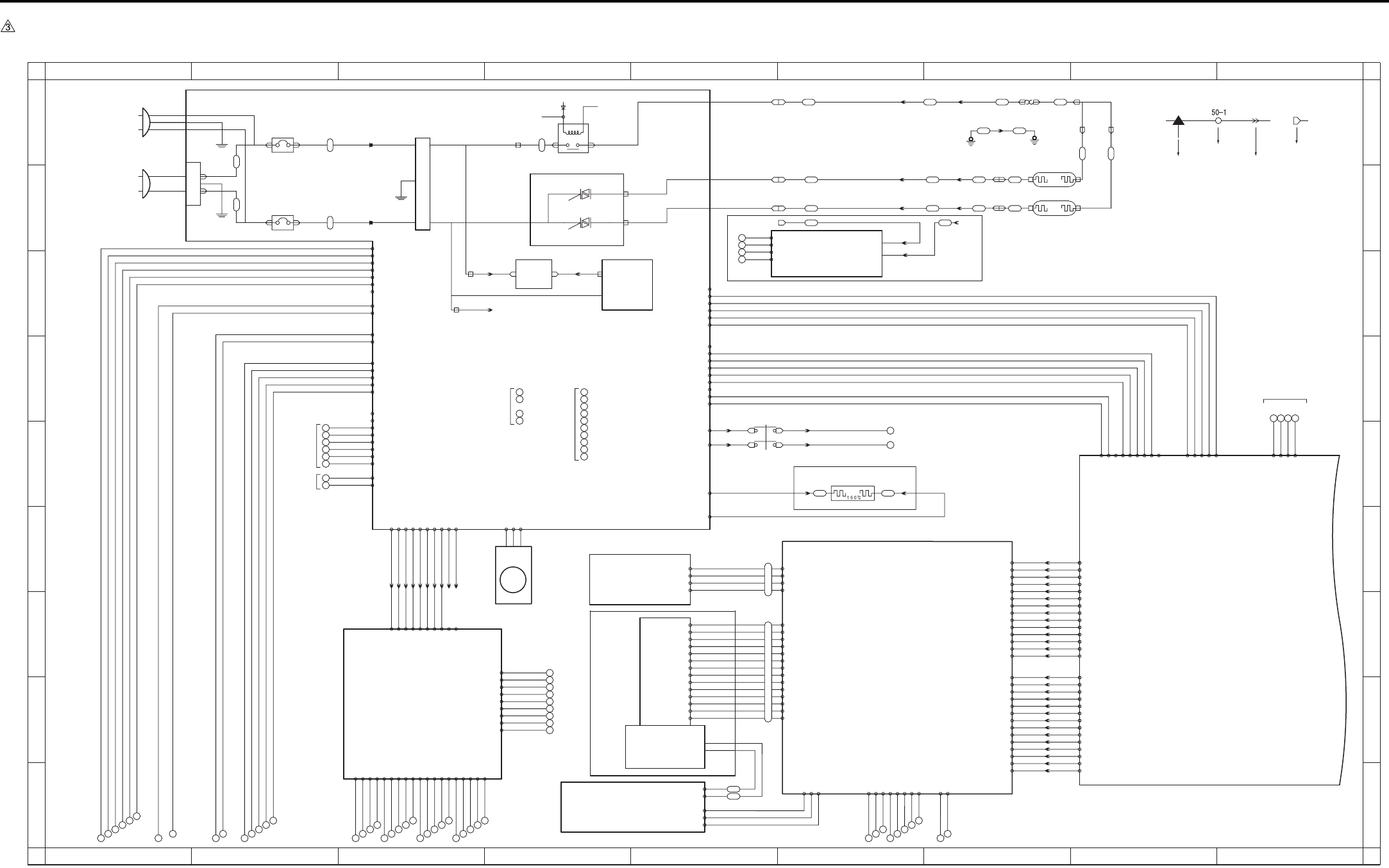
APPENDIX
Appendix-6
7.5 7235/7228/7222 Overall Wiring Diagram (1/4)
1
A
B
C
D
E
F
G
H
I
A
B
C
D
E
F
G
H
I
23456789
123456789
77 78 79 80 81 82 83
71 72 73 74 75 76
98 99
100 101 102
93 94
95 96 97
88 89
90 91 92
84 85
86 87
110 111 112
113 114
103 104
105 106 107
108 109
SWD24V
SWD24V
J24-1A
J24-2A J24-2B
J24-1B
24V 5-1
24V 5-2
LCDB
24V
5V
+12V
-12V
3-4 24V EM
3-5 FM1 EM
3-3 L3 CONT
3-2 L2 CONT
3-1 RL CONT
FT3
FT4
FT5
FT6
FT2
FT1
INLET
26 25 24 23
31
30
CN9-1
CN9-2
CN9-3
CN9-3
24V(C)
13
14
15
16
17
18
19
20
21
22
23
24
25
26
52-A8 SGND
52-A9 OPRTS
52-A10 OPRXD
52-B1 UD2
52-A3 UD1
52-A4 XSCL
52-B3 UD0
52-A1 UD3
52-A2 SGND
52-A5 SGND
52-A6 YD
52-A7 OPTXD
52-A11 SGND
52-A12 OPCTS
52-B2 SGND
52-B4 LP
52-B5 SGND
52-B6 LCDENB
52-B8 SGND
52-B9 OPINT
52-B10 MONIT
52-B11 5V
52-B12 5V
80-A12
80-A11
80-A10
80- A9
80- A8
80- A7
80- A5
80- A4
80- A3
80- A2
80- A1
80-B12
80-B11
80-B10
80- B9
80- B8
80- B7
80- B5
80- B4
80- B3
80- B2
80- B1
80- A6
80- B6
J38-A1 -A14
J38-A2 -A13
J38-A3 -A12
J38-A4 -A11
J38-A5 -A10
J38-A6 -A9
J38-A7 -A8
J38-A8 -A7
J38-A9 -A6
J38-A10 -A5
J38-A11 -A4
J38-A12 -A3
J38-B1 -B14
J38-B2 -B13
J38-B3 -B12
J38-B4 -B11
J38-B5 -B10
J38-B6 -B9
J38-B7 -B8
J38-B8 -B7
J38-B9 -B6
J38-B10 -B5
J38-B11 -B4
J38-B12 -B3
52-A13 DF INT
52-A14 APS INT
52-B7 POWER DOWN
52-B13 SYS STOP
52-B14 MODE
80-B13
80-A13
80-A14
80-B14
J38-B14 -B1
J38-B13 -B2
J38-A14 -A1
J38-A13 -A2
DC PSY
FT23
FT26
FT25
FT20 FT21
L2
J13-1
RT3
Ø4
RT4
Ø4
J21-01
J21-02
FT28
FT27 L3
J21-03
FT24
FT22
J13-4
J13-3
J13-2
J21-03
J24: 2 - 2
J24: 1 - 1
CN11-1
CN11-2
CN11-3
AC DRIVE
BT5
BT4
CR001
CR002
10-1 DRIVE
10-2 EM
10-3 PGND
AC(H)
BT1 BT3
CBR 1
CBR 2
AC(N)
BT2
PLUG
PLUG
53
52
51
50
for DCPS
PTC
935-2935-1
OPTIONAL
J23-2
J23-1
J23-4
J23-3
83- 1 X2
- 2 Y2
- 3 X1
- 4 Y1
84-3 5V
84-5 INV ON(PWM)
84-4 SGND
84-1 SGND
84-2 MONIT
84-9 SCAN6
84-10 RTN3
84-6 VR L
84-8 VR H
84-7 VR SIG
84-12 SGND
84-13 SW2
84-11 5V
FT7 FT8
RL1 POWER
RL1 CNT
MAIN RL
AC(H)
AC(H)
FT9 FT10
AC(N)
L2 DRIVE
L3 DRIVE
6-4 24V
6-6 24V
8-1 24V
2
3
5
6
8
10
11
12
for
BIAS
6-20 SGND
6-16 5V
6-12 PGND
6-10 PGND
8-3 PGND
for
DF320
6-18 N.C
6-14 N.C
J60: 1 - 1
J60: 2 - 2 7-1 24V
7-5 24V
J60: 3 - 3
J60: 4 - 4
J60: 7 - 7
J60: 8 - 8
J60: 9 - 9
J60:10 - 10
7-3 PGND
7-7 PGND
7-10 5V
7-14 SGND
- 6
- 5 7-25 RL PWR
7-26 RL PGND
7-6 24V
7-8 PGND
DB-211
DB-411
7-2 24V
7-4 PGND
7-12 5V
7-16 SGND
7-22 SGND
7-18 12V
7-20 SGND
6-2 24V
6-8 PGND
5-4 PGND
5-3 PGND
106- 4 PGND
106- 1 24V
106- 2 24V
106- 8 M150 F/R
106- 9 M150 CLOCK
106-13 PS152
106-14 PS153
106-15 PS154
106- 3 24V
106- 7 LT CLOSE
106-10 M150 CONT
106-11 SD151 DRIVE
106-12 PS155
106-16 PS151
106-18 5V
106-19 SGND
106- 5 PGND
106- 6 M151 DRIVE
106-17 LCT TYPE
CN99-3 SGND
CN99-2 L3 CONT
CN99-1 5V BT1
BT2
CN99-4 SGND
12V 42- 9
SGND 42- 8
N.C 42- 7
SGND 42- 6
12V 42- 5
SGND 42- 4
SGND 42- 3
5V 42- 2
5V 42- 1
SGND 43- 6
12V 43- 5
NMI 43- 4
24V EM 43- 3
5V EM 43- 2
SGND 500- 1
SGND 500- 2
5V 500- 3
5V 500- 4
N.C 43- 1
BT6
BT7
BT8
N.C 2-6
5V EM 2-5
24V EM 2-4
NMI 2-3
12V 2-2
SGND 2-1
12V 7-17
SGND 7-24
N.C 7-9
5V 7-11
SGND 7-13
SGND 7-15
SGND 7-21
N.C 7-23
12V 7-19
6-1 24V
6-3 24V
6-5 24V
6-7 PGND
6-9 PGND
6-11 PGND
6-13 5V
6-15 5V
6-17 SGND
6-19 SGND
for FNS
36
37
38
39
40
32
33
34
35
1-1 5V
1-2 5V
1-4 SGND
for OPTION
1-5 SGND
1-3 N.C
- 3 DIN
- 4 LP
- 9 D0
-10 D1
-11 D2
-12 D3
-13 VEE
86-14 VLCD
- 5 XSCL
- 1 DISPOFF
- 2 N.C
- 8 VEE(24V)
- 7 VSS(GND)
- 6 VDD(5V)
88- 3
- 2
- 1
89-1 FL HOT
-4 FL GND
24V 8-2
PGND 8-4
FM1
SCB 1/3
OB
PAKB
INV2
DCPS
DCPS cooling fan
for CB
PTC heater
SW1
NF
Noise filter
Circuit breaker/1
Circuit breaker/2
JAPAN AC100V 50/60Hz
EUROPE 200-240V 50Hz
USA 120V 60Hz
BL
FCB
Fixing heater
lamp/1
Fixing heater
lamp/2
Interlock switch
SW3
EUROPE Only
TS
Thermostat
Main power switch
Symbol
Crimp
Connector Faston
Relay connector
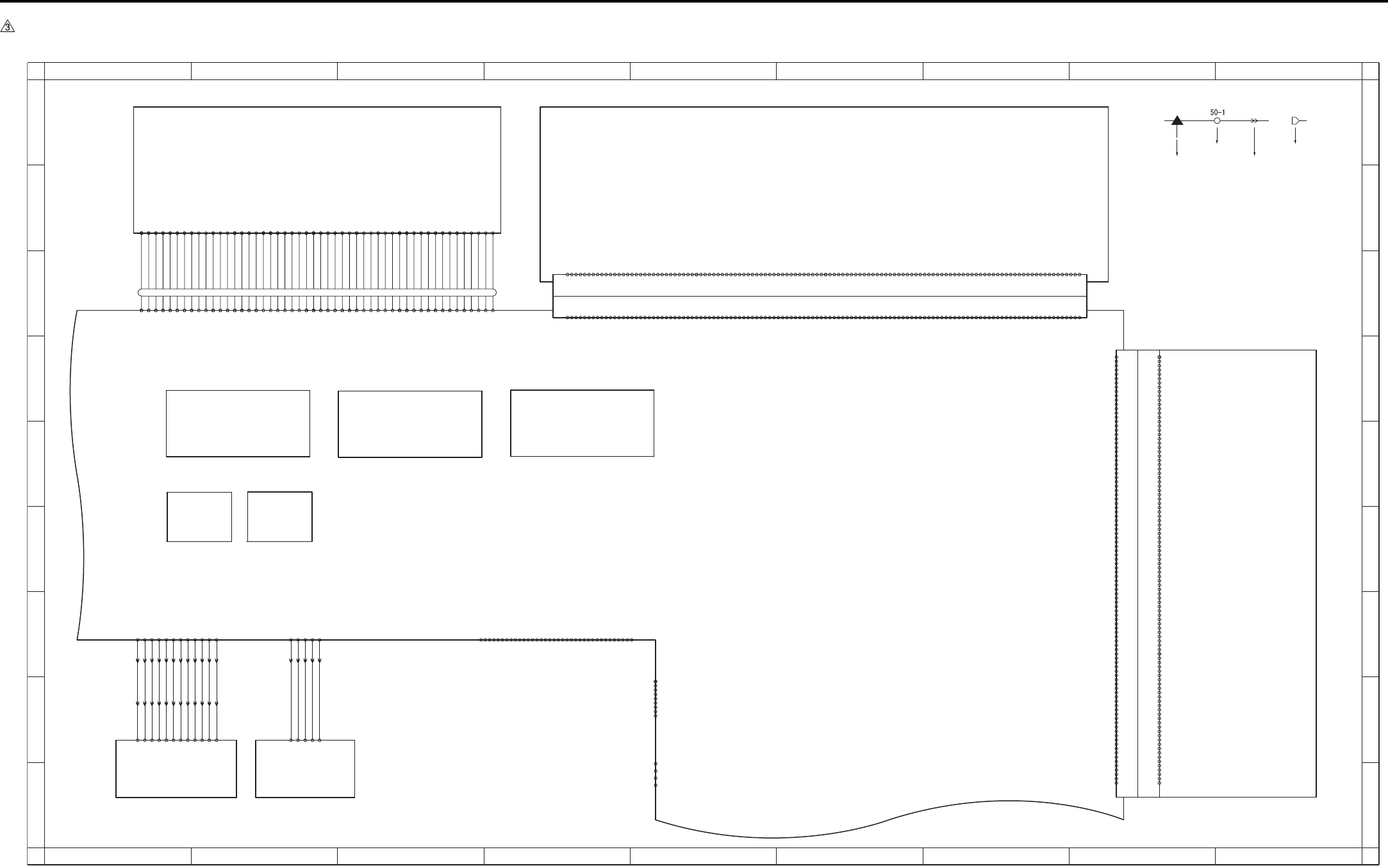
APPENDIX
Appendix-7
7.6 7235/7228/7222 Overall Wiring Diagram (2/4)
1
A
B
C
D
E
F
G
H
I
A
B
C
D
E
F
G
H
I
23456789
123456789
FK-103/FL-103
CN53 CN58,59
DIMM
CN501
HD-103 Type A
CN47
FAN
CN502
-A11 DRAM_D24
-A13 DRAM_D22
-A16 DRAM_D19
-A17 DRAM_D18
-A18 DRAM_D17
-A24 DRAM_D12
-A25 DRAM_D11
-A27 DRAM_D9
-A44 XFAX_RST
-A 5 DRAM_D30
400-A 1 SGND
-A 6 DRAM_D29
-A19 DRAM_D16
-A28 DRAM_D8
-A33 DRAM_D3
-A35 DRAM_D1
-A36 DRAM_D0
-A50 XIOSEL2
CN55 Board to Board Connector
-B13 EXOUT_D6
-B16 EXOUT_D3
-B17 EXOUT_D2
-B18 EXOUT_D1
-B24 EXIN_D3
-B25 EXIN_D4
-B27 EXIN_D6
-B39 MONITOR
-B 1 SGND
-B 8 XAHA1_INT
-B 9 XEXIN_ACK
-B19 EXOUT_D0
-B28 EXIN_D7
-B40 XRC_INT
-B51 L_A1
-B56 L_A6
-A 3 SGND
-A 2 BCLK12
-A 4 DRAM_D31
-A 7 DRAM_D28
-A 8 DRAM_D27
-A 9 DRAM_D26
-A10 DRAM_D25
-A12 DRAM_D23
-A14 DRAM_D21
-A15 DRAM_D20
-A20 5V
-A21 DRAM_D15
-A22 DRAM_D14
-A23 DRAM_D13
-A26 DRAM_D10
-A29 DRAM_D7
-A30 DRAM_D6
-A31 DRAM_D5
-A32 DRAM_D4
-A34 DRAM_D2
-A37 5V
-A38 SGND
-A39 VBAT
-A40 XWAIT
-A41 5V
-A42 5V
-A43 DR_CKE
-A45 XIRST
-A46 XICS5
-A47 XICS7
-A48 XIRD
-A49 XMWR
-A51 L_A20
-A52 L_A19
-A53 L_A18
-A54 L_A17
-A55 L_A16
-A56 L_A15
-A57 L_A14
-A58 L_A13
-A59 L_A12
-A60 L_A11
-B 2 BCLK5
-B 3 GND
-B 5 XFAX_COACK
-B 4 XFAX_CIACK
-B 6 XFAX_DIACK
-B 7 XFAX_DOACK
-B10 XEXOUT_ACK
-B11 -12V
-B12 EXOUT_D7
-B14 EXOUT_D5
-B15 EXOUT_D4
-B20 5V
-B21 EXIN_D0
-B22 EXIN_D1
-B23 EXIN_D2
-B26 EXIN_D5
-B29 XFAX_DRIVE
-B30 XEXOUT_REQ
-B31 XEXIN_REQ
-B32 XICS6
-B33 XFAX_DOREQ
-B34 XFAX_DIREQ
-B35 XFAX_COREQ
-B36 XFAX_CIREQ
-B37 5V
-B38 SGND
-B41 12V
-B42 PDA7
-B43 PDA6
-B44 PDA5
-B45 PDA4
-B46 PDA3
-B47 PDA2
-B48 PDA1
-B49 PDA0
-B50 L_A0
-B52 L_A2
-B53 L_A3
-B54 L_A4
-B55 L_A5
-B57 L_A7
-B58 L_A8
-B59 L_A9
-B60 L_A10
-39 APR
-48 12V
-43 5V
-31 +AD_D1
-14 SGND
-18 SGND
-20 SCLOCK
-12 +RCK
60- 1 SGND
- 3 CLAMP
- 5 BCLAMP
-13 -RCK
-15 SGND
-19 SCLOCK
-22 SDI
-23 SDO
-26 -AD_D0
-42 5V
-44 5V
-47 12V
-49 12V
- 2 TG
- 4 ACLAMP
- 6 SGND
- 7 SGMD
- 8 +TCK
- 9 -TCK
-10 SGND
-11 SGND
-16 +IN CLOCK
-17 -IN CLOCK
-21 *SEN
-24 SGND
-25 SGND
-27 +AD_D0
-28 SGND
-29 SGND
-30 -AD_D1
-32 SGND
-33 SGND
-34 -OUT_CLOCK
-35 +OUT_CLOCK
-36 SGND
-37 SGND
-38 ADRST
-40 SGND
-41 5V
-46 12V
-45 SGND
-50 SGND
-B33 PCI_C_BE0
-B12 PCI_AD29
-B16 PCI_C_BE3
-B20 PCI_AD18
-B26 PCI_C_BE1
-B31 PCI_AD8
-A20 PCI_AD17
-A21 PCI_C_BE2
-A26 PCI_AD15
56-B 1 XFAN
-B 2 FANHI
-B 9 XPCI_REQ0
-B19 PCI_AD20
CN56 Board to Board Connector(100pin)
-A24 XPCI_DEVSEL
56-A 1 XFAN_LK
-A 2 SGND
-A 4 SGND
-A 6 SGND
-A 7 SGND
-A 8 SGND
-A13 SGND
-A18 SGND
-A27 SGND
-A32 SGND
-A37 SGND
-A38 SGND
-A44 SGND
-A46 SGND
-A48 SGND
-A49 SGND
-A14 26/ISEL6
-A19 PCI_AD19
-A22 PCI_IRDY
-A23 SGND
-A25 PAR
-A28 PCI_AD13
-A29 PCI_AD11
-A30 PCI_AD9
-A31 PCI_AD7
-A33 PCI_AD6
-A34 PCI_AD4
-A35 PCI_AD2
-A36 PCI_AD0
-A39 5V
-A40 5V
-A41 5V
-A42 5V
-A43 5V
-A45 -12V
-A47 12V
-A50 12V
-B 4 SGND
-B 5 SGND
-B 6 SGND
-B 8 SGND
-B13 SGND
-B18 SGND
-B23 SGND
-B27 SGND
-B32 SGND
-B37 SGND
-B38 SGND
-B44 SGND
-B46 SGND
-B48 SGND
-B49 SGND
-B 7 BCLK3
-B11 PCI_AD31
-B14 PCI_AD27
-B15 PCI_AD25
-B17 PCI_AD22
-B21 PCI_AD16
-B22 XPCI_FRAME
-B24 XPCI_TRDY
-B25 XPCI_STOP
-B28 PCI_AD14
-B29 PCI_AD12
-B30 PCI_AD10
-B34 PCI_AD5
-B35 PCI_AD3
-B36 PCI_AD1
-B39 5V
-B40 5V
-B41 5V
-B42 5V
-B43 5V
-B45 -12V
-B47 12V
-B50 12V
-A 3 N.C
-A 5 /RST
-A 9 /GNT2
-A10 N.C
-A11 PCI_AD30
-A12 PCI_AD28
-A15 PCI_AD24
-A16 PCI_AD23
-A17 PCI_AD21
-B 3 N.C
-B10 N.C
-13 SLCT
-15 N.C
-16 SGND
-17 SGND
-19 SGND
-20 SGND
-19 SGND
-22 SGND
-10 ACK
-11 BUSY
-28 SGND
-29 SGND
-31 INT
-33 SGND
-34 N.C
-35 N.C
-27 SGND
-23 SGND
-24 SGND
-25 SGND
-26 SGND
40- 1 STROBE
- 2 DATA0
- 3 DATA1
- 4 DATA2
- 5 DATA3
- 6 DATA4
- 7 DATA5
- 8 DATA6
- 9 DATA7
-12 PE
-32 FAULT
-14 AUTOFD
-18 N.C
-30 HLOGIC
-36 SELECTIN
USB
- 3 TXD
57- 1 DCD
- 2 RXD
- 4 DTR
- 5 GND
- 6 DSR
- 7 RTS
- 8 CTS
KRDS I/F
- 9 RI
J52: 1 - 5
J52: 2 - 4
J52: 3 - 3
J52: 4 - 2
J52: 5 - 1
IP-424
48-1 VDD
48-4 GND
48-2 -Data
48-3 +Data
50-12
-11
-10
- 9
- 8
- 7
- 6
- 4
- 3
- 2
- 1
- 5
432-10 /S/H
432- 9 /ENB
432- 8 VIDEO+
432- 6 /ALM
432- 5 /RESET
432-11 SGND
432- 7 VIDEO-
432- 4 DACLK
432-12 LD 5V
432- 3 DI
432- 2 LOAD
432- 1 LPR 5V
J53:10 - 3
J53: 9 - 4
J53: 1 - 12
J53:12 - 1
J53:11 - 2
J53: 2 - 11
J53: 3 - 10
J53: 4 - 9
J53: 5 - 8
J53: 6 - 7
J53: 7 - 6
J53: 8 - 5
J50:10 - 3
J50: 9 - 4
J50: 1 - 12
J50:12 - 1
J50:11 - 2
J50: 2 - 11
J50: 3 - 10
J50: 4 - 9
J50: 5 - 8
J50: 6 - 7
J50: 7 - 6
J50: 8 - 5
-2
-3
-4
-5
51-1
431- 4 SGND
431- 2 SGND
431- 1 /INDPR
431- 3 /INDEX
431- 5 5V
46-37
46-38
46-39
46-41
46-42
46-31
46-27
46-14
46-15
46-16
46-18
46-19
46-20
46-22
46-23
46-21
46-17
46- 1
46- 2
46- 3
46- 5
46- 6
46- 7
46- 9
46-10
46-11
46-13
46-12
46- 8
46- 4
46-43
46-45
46-46
46-47
46-49
46-50
46-48
46-44
46-40
46-24
46-25
46-26
46-28
46-29
46-30
46-32
46-33
46-34
46-36
46-35
SCB 2/3
Battery
PRMB
ADB
LDB INDEX
Symbol
Crimp
Connector Faston
Relay connector
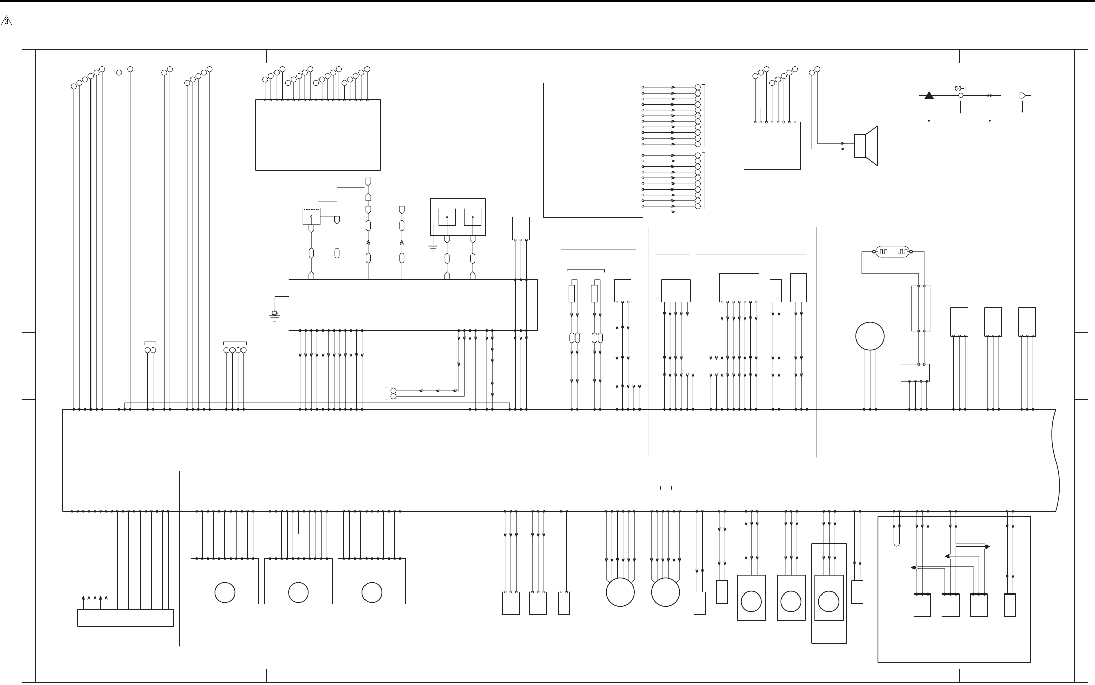
APPENDIX
Appendix-8
7.7 7235/7228/7222 Overall Wiring Diagram (3/4)
1
A
B
C
D
E
F
G
H
I
A
B
C
D
E
F
G
H
I
23456789
123456789
Scanner motor
77 78 79 80
81 82 83
71 72 73 74 75 76 98 99
100 101 102
93 94
95 96 97
88 89
90 91 92
84 85
86 87
110 111 112 113 114
103 104
105 106 107
108 109
FT36 FT37
FT38 FT39
FT34
FT31 FT32 FT33
FT30
FT40
FT35
M9
23-B11 24V
23-B1 5V
23-B3 CONT
23-B10 24V
23-B4 CLOCK
23-B5 F/R
M11
31-8 CLOCK
S.G -2
CONT -3
CLK -4
LD -6
H/L -7
P.G -8
P.G -9
24V -11
CW/CCW-5
24V -10
5V -1
S.G -2
CONT -3
CLK -4
LD -6
H/L -7
P.G -8
P.G -9
24V -11
CW/CCW-5
24V -10
5V -1
23-B2 SGND
23-B6 SGND
23-B8 PGND
23-B9 PGND
31-10 SGND
31-11 5V
31-9 CONT
31-7 N.C
31-6 SGND
31-5 N.C
31-4 PGND
31-3 PGND
31-2 24V
31-1 24V
S.G -2
CONT -3
CLK -4
LD -6
H/L -7
P.G -8
P.G -9
24V -11
CW/CCW-5
24V -10
5V -1
7235 only
RL CONT 25-A11
L2 CONT 25-A10
L3 CONT 25-A9
24V EM 25-A8
FM1 EM 25-A7
FUSING UNIT
951-1
PS 2
-3
-2
J13:A4 - A1
J13:A3 - A2
J13:A2 - A3
J13:A1 - A4
J13:B4 - B1
J13:B3 - B2
J13:B2 - B3
980:1 - 1
980:2 - 2
980:3 - 3
980:4 - 4
J18: 1 - 3
J18: 2 - 2
J18: 3 - 1
TH1 TH2
FM2
J28: 3 - 1
J28: 2 - 2
J28: 1 - 3
911: 3 - 1
911: 2 - 2
911: 1 - 3
M1
-3
TLD
984-1
-2
J05:3 - 1
J05:2 - 2
J05:1 - 3
915:6 - 1
915:5 - 2
915:4 - 3
915:3 - 4
915:2 - 5
915:1 - 6
M10
954-1
-2
-3
PS 5
J06:3 - 1
J06:2 - 2
J06:1 - 3
SD4
925:2 - 1
925:1 - 2
J29:2 - 1
J29:1 - 2
-2
-1
92-7
-6
-5
-4
-3
J15: 5 - 9
J15: 6 - 8
J15: 7 - 7
J15: 8 - 6
J15: 9 - 5
J15:11 - 3
J15:10 - 4
J16-2
J16-3
J16-4
J16-5
J16-6
J16-7
J16-8 J11: 1 - 7
J11: 2 - 6
J11: 3 - 5
J11: 4 - 4
J11: 5 - 3
J11: 7 - 1
J11: 6 - 2
12V 26-B9
DRUM.TH 26-B8
5V 26-B7
TNRIF 26-B10
TNOUT1 26-B11
TNOUT2 26-B12
SGND 26-B13
PCL
J15: 2 - 12
J15: 1 - 13
J16-14
J16-18
932:2 - 1
932:1 - 2
DRIVE 26-B17
24V 26-B16
N.C 26-B18
SD7
928:2 - 1
928:1 - 2
J15: 4 - 10
J15: 3 - 11
J16-15
J16-16
24V 26-B15
DRIVE 26-B14
983-1
-2
-4
J17-2
J17-3
-5
J17-5
J17-9 -3
TDS
J14: 5 - 2
J14: 6 - 1
J14: 4 - 3
J14: 3 - 4
J14: 2
J14: 1
CONT 25-A1
12V 25-A2
TDS ANG 25-A3
SGND 25-A4
N.C 25-A6
N.C 25-A5
PS17
5V 16-7
PS 16-8
SGND 16-9
PS15
SGND 16-4
PS 16-5
5V 16-6
963-3
-2
-1
PS14
SGND 16-1
PS 16-2
5V 16-3
964-3
-2
-1
966-3
-2
-1
M2
V 32-2
W 32-3
U 32-1
931-4
-3
930-1 L.V.
-3 H.V.
L1
-1
96-1
96-3
97-3
97-1
-2
24V 33-1
L1 CONT 33-2
L1 EM 33-3
PGND 33-4
J09-9
J09-8
J09-7 70- 3
70- 2
70- 1
73- 3
73- 2
73- 1
MC1
920: 2 - 1
920: 1 - 2
61
62
63
64
65
66
67
68
69
70
SGND
FS SIN
SGND
SGND
60
FS CTS
SGND
N.C
FS RTS
N.C
SGND
FS SOUT
300:B11- B11
300:B10- B10
300:B9 - B9
300:B8 - B8
300:B7 - B7
300:B6 - B6
300:B5 - B5
300:B4 - B4
300:B3 - B3
300:B2 - B2
300:B1 - B1
for ENGINE
J15:12 - 2
J15:13 - 1 J16-12
J16-14
N.C 26-B6
N.C 26-B5
70- 7
24V
PGND
70- 9
70- 8
70- 5
70- 4
70- 6
J25-4
J17-8 J17-11J25-2
J09-6
J09-5
J09-4
J09-3
J09-2
J09-1
J17-12J17-7
J25-5J25-1
SDC.SIG 15-A2
S.FB 15-A1 J10:12 - 1
J10:11 - 2
J10:10 - 3
J10: 9 - 4
J10: 8 - 5
J10: 7 - 6
J10: 6 - 7
J10: 5 - 8
J10: 4 - 9
J10: 3 - 10
J10: 2 - 11
J10: 1 - 12
SAC.SIG 15-A3
S.CONT 15-A4
T.FB 15-A5
T.SIG 15-A6
T.CONT 15-A7
G.CONT 15-A8
C.FB 15-A9
GRID.SIG 15-A10
CHG.SIG 15-A11
C.CONT 15-A12
DEV UNIT DRUM CARTRIGE
FM3
912: 3 - 1
912: 2 - 2
912: 1 - 3
J38: 3 - 4
J38: 2 - 5
J38: 1 - 6
J42:2 - 2
J42:3 - 3
972-1
-2
-3
PS23
J42:5 - 5
J42:6 - 6
974-1
-2
-3
PS25
J42:10- 10
J42:11- 11
J42:4 - 4
973-1
-2
-3
PS24
IT-101
SD8
939: 1 - 2
939: 2 - 1
J42:8 - 8
J42:9 - 9
M4
903:6 - 1
903:5 - 2
903:4 - 3
903:3 - 4
903:2 - 5
903:1 - 6
914: 3 - 1
914: 2 - 2
914: 1 - 3
FM6
J38: 6 - 1
J38: 5 - 2
J38: 4 - 3
982-1
-2
-3
HUM1
SD9
927:2 - 1
927:1 - 2
986-2
986-1
TC
50 51 52 53
5V 14- 4
L3 CONT 14- 3
SGND 14- 2
SGND 14- 1
J12: 9 - 1
J12: 8 - 2
J12: 7 - 3
J12: 6 - 4
J12: 5 - 5
J12: 4 - 6
J12: 3 - 7
SGND 18- 7
TH2 ANG 18- 8
SGND 18-10
PS 18-11
SGND 18- 9
N.C 18-14
N.C 18-13 J12: 2 - 8
J12: 1 - 9
5V 18-12
TH1 ANG 18- 6
18-4 LOCK
18-5 PGND
18-3 DRIVE
Perdita/Pongo:
Discovery:
23-A1 24V
23-A11 5V
23-A8 CLOCK
23-A9 CONT
23-A6 LOCK
23-A2 24V
23-A10 SGND
23-A4 PGND
23-A3 PGND
23-A7 SGND
29-B14 SGND
29-B16 5V
29-B15 TLD ANG
29-A14 B
29-A13 B
29-A11 A
29-A12 A
29-A16 24V
29-A15 24V
29-B12 PS
29-B13 5V
29-B11 SGND
29-A7 DRIVE
29-A8 24V
J16-20
to BIAS
72- 5
CHARGER
GRID
J16-11
72- 1
to GUIDE
PLATE
29-A10 DRIVE
29-A9 24V
85 - 5
85 - 1
85 - 2
85 - 3
85 - 4
85 - 8
85 - 7
85 - 6
29-A2 EM
29-A1 DRIVE
29-A3 PGND
29-B1 A
29-B2 A
29-B3 B
29-B4 B
29-B6 24V
29-B5 24V
29-A5 EM
29-A6 PGND
29-A4 DRIVE
18-1 DRIVE
18-2 24V
29-B10 DRIVE
29-B9 24V
24V 21- 6
5V 21- 4
SGND 21- 3
SGND 21- 2
12V 21- 1
PGND 21- 5
SGND 27- 6
HUM1 ANG 27- 7
N.C 27- 5
5V 27- 8
300:A10- A10
300:A9 - A9
300:A8 - A8
300:A7 - A7
300:A6 - A6
300:A5 - A5
300:A4 - A4
300:A3 - A3
300:A2 - A2
300:A1 - A1
300:A11- A11
13
14
15
16
17
18
19
20
21
22
24V
24V
24V
PGND
PGND
PGND
5V
5V
SGND
SGND
for DCPS
FS-113
FS-114
B.SIG 27- 2
B.CONT 27- 1
for
DCPS
24V 27- 4
PGND 27- 3
12
11
3130
LT-203
24V 20- 1
24V 20- 2
PGND 20- 3
PGND 20- 4
PGND 19- 3
PGND 19- 2
24V 19- 1
110-19
110-18
110-17
110-16
110-15
110-14
110-13
110-12
110-11
110- 9
110- 8
110- 7
110- 6
110- 5
110- 4
110- 3
110- 2
110- 1
110-10
71- 1
71- 2
71- 3
71- 4
71- 7
71- 9
71-10
71-11
71-12
71- 8
71- 6
71- 5
514: 1 - 2
514: 2 - 1
38- 1 PS
38- 2 SGND
38- 8 SGND
38- 3 5V
38- 5 SGND
38- 9 IT.SET
38- 4 PS
38- 7 DRIVE
38- 6 24V
35-1
35-2
35-4
35-3
-10 PGND
COPY VENDER
35-5
-8 /CPF0
-9 /CPF1
-4 VEN.RXD
-3 VEN.CTS
-6 VEN.RTS
37-1 VEN.TXD
36-1 /M1
-2 /PF
-3 /PS0
-4 /PS1
-5 /PS2
-6 /PS3
-7 /SIDE
-2 PGND
-5 N.C
-7 PGND
-8 5V
CB 1/2
PSW2B
/SW2
Main motor Paper feed motor Fixing motor
Toner level
sensor
Toner bottle
sensor
Total counter
Toner supply
motor/2
Toner supply
motor/1
Cleaning
web
solenoid
Registration
clutch Internal
dehumidifying
fan/1
Internal
dehumidifying
fan/2
IT exit
sensor/U
IT door
sensor
IT exit
sensor/L
Toner
solenoid
Speaker
Toner control
sensor board
Pre-
charging
lamp
Separation
claw
solenoid
TCSB
Toner density sensor
Fixing
temperature
sensor/1
Fixing
temperature
sensor/2
Fixing exit sensor
Separation Transfer
Humidity sensor
for SW3 EUROPE only
for FCB
Exposure lamp
INV1
L1INVB
APS sensor APS timing
sensor
Scanner home
position sensor
Gate
solenoid
Fixing
cooling
fan
HV
Symbol
Crimp
Connector Faston
Relay connector
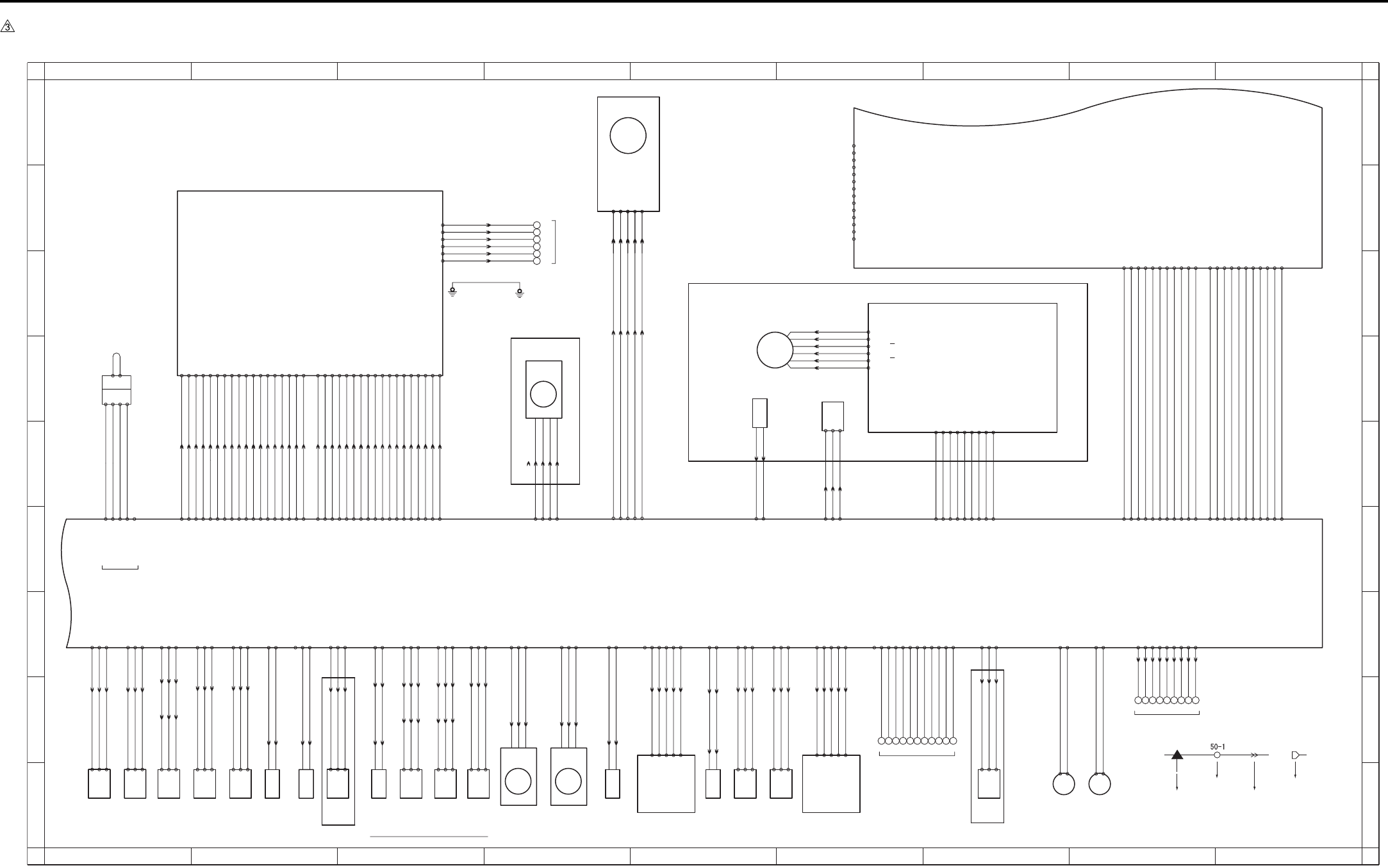
APPENDIX
Appendix-9
7.8 7235/7228/7222 Overall Wiring Diagram (4/4)
1
A
B
C
D
E
F
G
H
I
A
B
C
D
E
F
G
H
I
23456789
123456789
DF-320 AD-307
(JAPAN ONLY)
TSL
Transfer
synchro-
nization
lamp
933:2 - 1
1 - 2
J02: 2 - 6
J02: 1 - 7 24-A13 SGND
24-A12 DRIVE
M8
907-1
-2 26-B1 DRIVE
26-B2 24V
SD2
923: 2 - 1
923: 1 - 2 25-B2 DRIVE
25-B1 24V
959-1
-3
-2
J03:11 - 1
J03:10 - 2
J03: 9 - 3
PS 10
24-A11 5V
24-A9 SGND
24-A10 PS
960-1
-3
-2
J03: 8 - 4
J03: 7 - 5
J03: 6 - 6
PS 11
24-A8 5V
24-A6 SGND
24-A7 PS
961-1
-2
-3
PS 12
25-B14 5V
25-B12 SGND
J32:3 - 1
J32:2 - 2
J32:1 - 3 25-B13 PS
M7
906-1
-2 26-B3 DRIVE
26-B4 24V
956-1
-3
-2
J01: 3 - 7
J01: 2 - 8
J01: 1 - 9 25-B4 PS
PS 7
25-B5 5V
25-B3 SGND
957-1
-3
-2
J01: 6 - 4
J01: 5 - 5
J01: 4 - 6 25-B7 PS
PS 8
25-B6 SGND
25-B8 5V
958-1
-2
-3 25-B16 PS
PS 9
25-B15 SGND
25-B17 5V
J31:3 - 1
J31:2 - 2
J31:1 - 3
25-B10 PS
J01:9 - 1
J01:8 - 2
J01:7 - 3 25-B9 SGND
950-1
-2
-3
PS 1
J33:3 - 1
J33:2 - 2
J33:1 - 3
25-B11 5V
MC2
921: 2 - 1
921: 1 - 2 24-B2 DRIVE
24-B1 24V
SD3
924: 2 - 1
924: 1 - 2
J04:11 - 1
J04:10 - 2 24-B18 DRIVE
BYPASS TRAY
24-B19 24V
24-B10 PS
J04: 3 - 9
PS13
962-1
-2
-3
24-B11 5V
24-B9 SGND
J04: 2 - 10
J04: 1 - 11
M6
905: 6 - 1
905: 5 - 2
905: 4 - 3
905: 3 - 4
905: 2 - 5
905: 1 - 6 71-1 A
71-6 24V
71-5 24V
71-3 B
71-2 A
71-4 B
-3
-2
953-1
PS 4
J30:3 - 1
J30:2 - 2
J30:1 - 3
5V 15-A15
PS 15-A14
SGND 15-A13
for DB UNIT
J61 : 1 - 9
J61 : 2 - 8
J61 : 3 - 7
J61 : 4 - 6
J61 : 5 - 5
J61 : 6 - 4
J61 : 7 - 3
J61 : 8 - 2
J61 : 9 - 1
323334353637383940
26-A1 DB_RTS
26-A4 DB_CTS
26-A2 SGND
26-A3 DB_RXD
26-A5 SGND
26-A6 DB_TXD
26-A9 DB_RST
26-A8 LCT_EXIT
26-A7 DB_EXIT
24-B16 PS
J04: 9 - 3
J04: 8 - 4
J04: 7 - 5
PS20
969-1
-2
-3
24-B17 5V
24-B15 SGND
J08: 6 - 1
J08: 5 - 2
J08: 4 - 3
J04: 6 - 6
J04: 5 - 7
J04: 4 - 8
VR1
98 -3
-2
-1
24-B14 SGND
24-B12 5V
J08: 3 - 4
J08: 2 - 5
J08: 1 - 6 24-B13 VR
25-A13 PS
J41:3 - 1
J41:2 - 2
J41:1 - 3
971-3
-2
-1
PS22
Timming
sensor/L
7235/7228 only 7235/7228 only
25-A14 SGND
25-A12 5V
SD1
922: 2 - 1
922: 1 - 2 25-A15 DRIVE
25-A16 24V
25-A17 N.C
6061626364656667686970
For Finisher
15-B14 SGND
15-B13 SGND
15-B12 FS CTS
15-B11 SGND
15-B8 SGND
15-B7 FS RTS
15-B6 N.C
15-B5 SGND
15-B4 FS TXD
15-B15 N.C
15-B10 N.C
15-B9 FS RXD
90-1
-2
-4
-3
-5
J02: 7 - 1
J02: 6 - 2
J02: 5 - 3
24-A14 SIZE.UP.D
24-A15 SIZE.UP.C
24-A16 SIZE.UP.B
24-A17 SIZE.UP.A
J02: 3 - 5
J02: 4 - 4
24-A18 SGND
24-A19 N.C
91-1
-2
-4
-3
-5
J03: 5 - 7
J03: 4 - 8
J03: 3 - 9
J03: 2 - 10
J03: 1 - 11
24-A4 SIZE.LOW.A
24-A3 SIZE.LOW.B
24-A2 SIZE.LOW.C
24-A1 SIZE.LOW.D
24-A5 SGND
904-1
-2
-3
M 5
-4
-5
J51:1 - 5
J51:2 - 4
J51:3 - 3
J51:4 - 2
J51:5 - 1
CLOCK 22-5
LCCK 22-4
DRIVE 22-3
PGND 22-2
24V 22-1
J54:1 - 5
J54:2 - 4
J54:3 - 3
J54:4 - 2
J54:5 - 1
J54:1 - 4
J54:2 - 3
J54:3 - 2
J54:4 - 1
SD5
926:2 - 1
1 - 2
RT3
Ø3
200: 1 - 1
200: 2 - 2
200: 3 - 3
200: 4 - 4
200: 5 - 5
200: 6 - 6
24V
24V
5V
SGND
PGND
PGND
15-B2 PS
J40:3 - 1
J40:2 - 2
J40:1 - 3
970-3
-2
-1
PS21
Timming
sensor/U
15-B1 5V
15-B3 SGND
985A-3
-1
-2
-4
CN985A
CN985B
985B-1
985B-2
913: 3 - 1
913: 2 - 2
913: 1 - 3
FM5
24-B7 EM
24-B8 PGND
24-B6 DRIVE
68-A9
68-A7
68-A10
68-A6
68-A11
68-A12
68-A13
68-A14
68-A15
68-A16
68-A17
68-A18
68-B16
68-B17
68-A5
68-B2
68-B3
68-B4
68-A4
68-A2
68-A3
68-B5
68-B6
68-B7
68-B8
68-B9
68-B10
68-B11
68-B12
68-B13
68-B15
68-B18
68-A1
68-B1
68-B14
68-A8
910: 3 - 1
910: 2 - 2
910: 1 - 3
FM4
24-B4 EM
24-B5 PGND
24-B3 DRIVE
M6 CONT 26-A16
24V 26-A17
24V 26-A18
5V 26-A13
M6 CLOCK 26-A14
M6 F/R 26-A15
70-7
70-1
70-2
70-4
70-5
SGND 26-A12
SGND 26-A10 70-9
70-8SGND 26-A11
70-3
70-6
EM 39-2
DRIVE 39-1
FM7
SGND 39-4
N.C 39-3
DRIVE 29-B7
24V 29-B8
44-A3
44-A4
44-A8
44-A11
44-A1
44-A2
44-A5
44-A6
44-A7
44-A9
44-A10
44-B1
B VV 28-A1
TONYY 28-A2
P VV 28-A3
S VV 28-A4
SGND 28-A6
EE VV 28-A5
EG RTS 28-A7
EG TXD 28-A8
EG CTS 28-A9
EG RXD 28-A10
SGND 28-A11
DDF VV 28-B11
N.C 28-B10
EG INT 28-B5
EG RST 28-B4
PS301 28-B6
APS TIM 28-B7
44-B4
44-B7
44-B8
SGND 28-B1
5V SYS 28-B2
SGND 28-B3 44-B9
44-B11
FIX OK 28-B9
SGND 28-B8
44-B10
44-B6
44-B5
44-B3
44-B2
M301 F/R 17-A3
M301 EM 17-A4
M301 RST 17-A5
M301 RTN 17-A6
SD301 DRIVE 17-A8
SGND 17-A7
PS301 17-A9
PS304 17-A12
PS305 17-A13
SD302 DRIVE 17-B9
PS306 17-B6
PS308 17-B7
PS309 17-B8
M303 F/R 17-B13
M303 EM 17-B14
M301 CLOCK 17-A1
SGND 17-A2
PS302 17-A10
PS303 17-A11
M303 V0 17-B4
M303 V1 17-B5
M302 V0 17-B2
M302 V1 17-B3
M301 V0 17-B1
VR301 17-A14 201:A5 - A14
201:A6 - A13
201:A7 - A12
201:A8 - A11
201:A18- A1
201:A17- A2
201:A16- A3
201:A15- A4
201:A14- A5
201:A13- A6
201:A12- A7
201:A11- A8
201:A10- A9
201:A9 - A10
201:B5 - B14
201:B6 - B13
201:B7 - B12
201:B8 - B11
201:B10- B9
201:B9 - B10
201:B11- B8
201:B12- B7
201:B13- B6
201:B14- B5
201:B15- B4
201:B16- B3
201:B17- B2
201:B18- B1
M302 EM 17-B15
SGND 17-B16
M302 CLOCK 17-B17 201:B2 - B17
201:B3 - B16
201:B4 - B15
SD303 CONT 17-A15
FM301 CONT 17-A16
FM301 EM 17-A17 201:A2 - A17
201:A3 - A16
201:A4 - A15
SGND 17-B10
M303 CLOCK 17-B11
SGND 17-B12
201:B1 - B18
201:A1 - A18
5V 17-A18
SGND 17-B18
LAN
2
3
5
6
8
10
for DCPS
DRIVE 35- 4
N.C 35- 5
SGND 35- 3
SIG 35- 2
24V 35- 1
41-1 TX+
41-2 TX-
41-3 RX+
41-4 N.C
41-5 N.C
41-6 RX-
41-7 N.C
41-8 N.C
41-9 FG
41-11 VDD1
41-10 FG
41-11 LED1
41-11 VDD2
41-11 LED2
RT3
Ø3
SCB 3/3
for KC CB 2/2
PFDB/U PFDB/L
Tray set
sensor/L
No paper
sensor
Tray set
sensor/U
Registration
sensor
Upper limit
sensor
1st paper
feed
solenoid/L
1st paper
feed
solenoid/U
By-pass
paper feed
solenoid
By-pass
no paper
sensor
By-pass
tray paper
size sensor
By-pass
tray paper
size VR
Loop clutch Upper limit
sensor/L
No paper
sensor/U
Tray
motor/L
Tray
motor/U
Internal cooling
fan/1
Developing
suction fan
ADU sensor
ADU motor
ADU gate
solenoid
Polygon cooling fan
Polygon motor
Key counter
KC
(Option)
ADU is standard equipment for 7235/7228/7222
7235 only
ADUDB
Symbol
Crimp
Connector Faston
Relay connector

APPENDIX
Appendix-10
Symbol Part name Location Symbol Part name Location Symbol Part name Location
COPY VENDER COPY VENDER Appendix-3 1-I M1 Main motor Appendix-3 2-H PS24 IT exit sensor /L Appendix-3 9-H
AD-307 AD-307 Appendix-4 5-C M2 Scanner motor Appendix-3 8-D PS25 IT door sensor Appendix-3 8-H
DB-211 DB-211 Appendix-1 2-G M4 Toner supply motor /1 Appendix-3 5-H TH1 Fixing temperature sensor /1 Appendix-3 5-D
DB-411 DB-411 Appendix-1 2-G M5 Polygon motor Appendix-4 4-A TH2 Fixing temperature sensor /2 Appendix-3 5-D
DF-320 DF-320 Appendix-4 1-B M6 ADU motor Appendix-4 5-D HUM1 Humidity sensor Appendix-3 5-C
DIMM DIMM Appendix-2 3-D M7 Tray motor /U Appendix-4 7-I TDS Toner density sensor Appendix-3 6-D
FK-103/FL-103 FK-103/FL-103 Appendix-2 4-A M8 Tray motor /L Appendix-4 8-I TLD Toner level sensor Appendix-3 5-H
FS-113 FS-113 Appendix-3 5-A M9 Paper feed motor Appendix-3 3-H TS Thermostat Appendix-1 7-A
FS-114 FS-114 Appendix-3 5-A M10 Toner supply motor /2 Appendix-3 6-H SW1 Main power switch Appendix-1 4-C
HD-103 Type A HD-103 Appendix-2 1-D M11 Fixing motor Appendix-4 7-I SW2 Sub power switch Appendix-3 7-A
IP-424 IP-424 Appendix-2 8-D FM1 DCPS cooling fan Appendix-1 4-F SW3 Interlock switch Appendix-1 5-E
IT-101 IT-101 Appendix-3 8-G FM2 Fixing cooling fan Appendix-3 7-H VR1 By-pass tray paper size VR Appendix-4 3-I
KC Key counter Appendix-4 1-D FM3 Internal dehumidifying fan /1 Appendix-3 7-H PTC PTC heater Appendix-1 6-E
LT-203 LT-203 Appendix-3 2-A FM4 Internal cooling fan /1 Appendix-4 4-I BATTERY Battery Appendix-2 1-E
TC Total counter Appendix-3 5-H FM5 Developing suction fan Appendix-4 4-I
ADB A/D conversion board Appendix-2 1-A FM6 Internal dehumidifying fan /2 Appendix-3 7-H
ADUDB ADU drive board Appendix-4 6-C FM7 Polygon cooling fan Appendix-4 4-D
CB Main control board Appendix-3 1-F MC1 Registration clutch Appendix-3 6-H
FCB Fixing control board Appendix-1 5-B MC2 Loop clutch Appendix-4 4-I
INDEX Index sensor board Appendix-2 2-H SD1 1st paper feed solenoid /U Appendix-4 2-I
L1INVB Exposure lamp power supply board Appendix-3 8-D SD2 1st paper feed solenoid /L Appendix-4 2-I
LCDB Display board Appendix-1 5-G SD3 By-pass paper feed solenoid Appendix-4 3-I
LDB LD drive board Appendix-2 1-H SD4 Cleaning web solenoid Appendix-3 6-H
OB Operation board Appendix-1 6-F SD5 ADU gate solenoid Appendix-4 5-D
PAKB Panel key board Appendix-1 4-F SD7 Separation claw solenoid Appendix-3 7-D
PFDB/L Paper feed detection board /L Appendix-4 6-H SD8 Gate solenoid Appendix-3 9-H
PFDB/U Paper feed detection board /U Appendix-4 5-H SD9 Toner solenoid Appendix-3 8-H
PRMB Parameter memory board Appendix-2 4-D PS1 Registration sensor Appendix-4 1-I
PSW2B Power SW2 board Appendix-3 7-A PS2 Fixing exit sensor Appendix-3 6-D
SCB System control board Appendix-1 8-E PS4 ADU sensor Appendix-4 6-D
TCSB Toner control sensor board Appendix-3 6-D PS5 Toner bottle sensor Appendix-3 5-H
DCPS DC power supply unit Appendix-1 1-A PS7 Upper limit sensor /U Appendix-4 2-I
HV High voltage unit Appendix-3 3-D PS8 No paper sensor /L Appendix-4 2-I
INV1 Exposure lamp inverter Appendix-3 8-E PS9 Tray set sensor /U Appendix-4 1-I
INV2 Display inverter Appendix-1 4-I PS10 Upper limit sensor /L Appendix-4 5-I
CBR1 Circuit breaker /1 Appendix-1 2-A PS11 No paper sensor /U Appendix-4 5-I
CBR2 Circuit breaker /2 Appendix-1 2-B PS12 Tray set sensor /L Appendix-4 1-I
NF Noise filter Appendix-1 3-A PS13 By-pass no paper sensor Appendix-4 3-I
L1 Exposure lamp Appendix-3 8-C PS14 Scanner home position sensor Appendix-3 9-D
L2 Fixing heater lamp /1 Appendix-1 7-B PS15 APS timing sensor Appendix-3 9-D
L3 Fixing heater lamp /2 Appendix-1 7-B PS17 APS sensor Appendix-3 8-D
PCL Pre-charging lamp Appendix-3 7-D PS20 By-pass tray paper size sensor Appendix-4 3-I
TSL Transfer synchronization lamp Appendix-4 5-I PS21 Timing sensor /U Appendix-4 7-I
LCD LCD Appendix-1 5-G PS22 Timing sensor /L Appendix-4 2-I
BL Back light Appendix-1 4-H PS23 IT exit sensor /U Appendix-3 8-H

APPENDIX
Appendix-11
7.9 FS-114 Overall Wiring Diagram
1
A
B
C
D
E
F
G
H
I
A
B
C
D
E
F
G
H
I
23456789
123456789
SK-114
SK-114
SK-114
PK-114
Staple Needle Empty Detect Sensor
Staple Home Detect Sensor
Staple Selfpriming Detect Sensor
Punch Unit Setting 1st Detection
GND
Chopper Unit Setting Detection
GND
Punch Unit Setting 2nd Detection
GND
Punch Unit Setting 3rd Detection
GND
Symbol
Crimp
Connector Faston
Relay connector

APPENDIX
Appendix-12
Symbol Part name Location
PK-114 PK-114 1-E
SK-114 SK-114 1-A, 1-D
CL1-FN Registration clutch 7-B
M1-FN Exit motor 7-E
M2-FN Transport motor 7-C
M3-FN Entrance motor 7-C
M4-FN Allignment motor 1 7-G
M5-FN Allignment motor 2 7-F
M6-FN Exit open/close motor 7-B
M7-FN Stapling unit moving motor 7-E
M11-FN Elevator motor 7-G
M12-FN Shutter opening motor 7-G
PC3-FN Elevator tray home position sensor 7-I
PC4-FN Entrance sensor 7-B
PC5-FN Transport sensor 7-A
PC6-FN Alignment home position sensor 1 7-F
PC7-FN Alignment home position sensor 2 7-F
PC8-FN Storage tray detecting sensor 7-E
PC10-FN Staple home position sensor 7-D
PC11-FN Exit paddle home position sensor 7-D
PC12-FN Exit roller home position sensor 7-A
PC14-FN Elevator tray lower limit sensor 7-H
PC15-FN Top face detection sensor 7-I
PC16-FN Shutter home position sensor 7-H
S1-FN Front cover open/close detection SW 2-C
S2-FN Shutter detection SW 7-H
S3-FN Elevate tray upper/lower limit SW 7-G
S4-FN Transport jam detection SW 7-A
SL1-FN Storage paddle solenoid 7-B
SL2-FN Exit paddle solenoid 7-C
M1-PK Punch motor 2-G
PC1-PK Punch trash full sensor 2-E
PC2-PK Punch motor pulse sensor 2-F
PC3-PK Punch positioning sensor 1 2-F
PC4-PK Punch positioning sensor 2 2-F
PWB-A FN Main control board 3-B
PWB-B FN Elevator board 5-H
