Kontron Embedded Technology REVO-V3-12 Notebook PC User Manual Contents
Kontron Embedded Technology Inc Notebook PC Contents
Contents
- 1. User Manual Part 1
- 2. User Manual Part 2
- 3. User Manual Part 3
User Manual Part 3
Power Management Modes
Windows
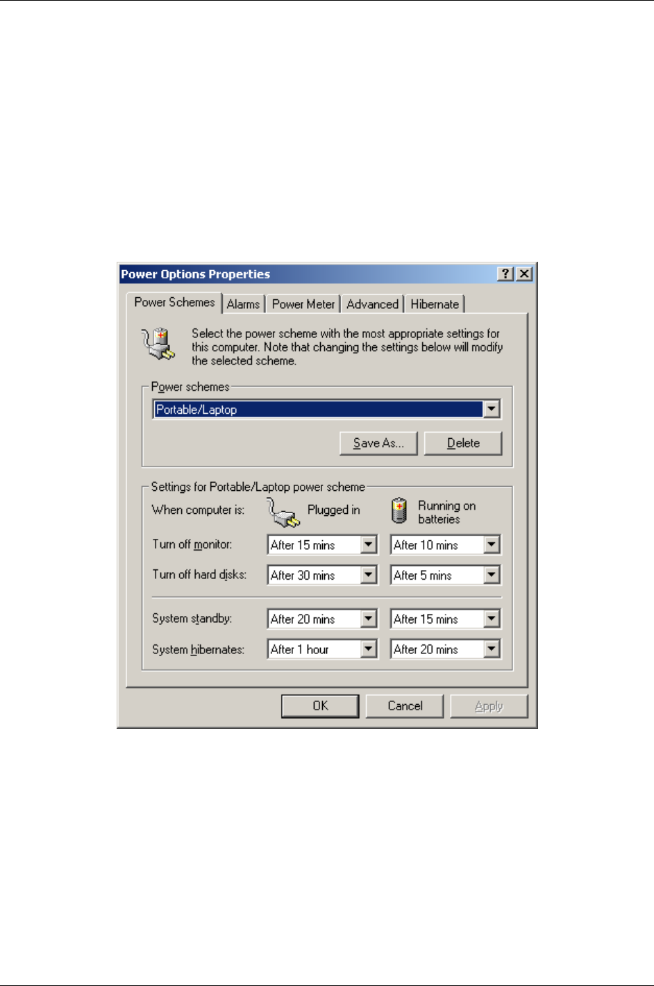
Your ReVolution will manage power consumption while running the Windows operating system, based on the settings
in Windows Control Panel power options. To maximize battery run-time, be aware of the settings affecting power
consumption. In addition to Control Panel power options, the following items can influence battery run time:
• LCD backlight level
• Intel Speed Step mode
• Wireless network settings
Set the power management properties for your application in Windows Power Options.
If you are running an operating system that does not fully support power management (APM or ACPI), such as
Legacy, you can set basic power management features in BIOS setup. Refer to the “Phoenix BIOS Setup” section
in this document for these settings.
34 02/25/03 ReVolution User Manual 1.00

Battery Operations
The right bay battery is the primary battery source and is identified as battery number 1. The left bay battery is the
secondary battery source identified as battery number 2. Using two or more batteries will allow you to swap charged
batteries into the module bays for extended portable operation.
Single battery operation
The ReVolution running on a single battery will deplete battery charge until an alarm level is met then trigger the
action set for that alarm. Set the alarm level and action in Power Options in Windows Control Panel.
Stand-by battery operation
When running the ReVolution with two charged batteries, the secondary battery will be depleted first. The primary
battery will power the ReVolution when the secondary battery is empty, keeping the ReVolution running as a stand-by
battery. Replace the depleted secondary battery with a charged battery to resume powering the ReVolution on the
secondary battery.
Alternate battery operation
Place a battery in either bay and run the ReVolution until a low battery message is displayed. Place a charged battery
in the remaining open bay to continue operation and remove the discharged battery.
ReVolution User Manual 1.00 02/25/03 35
Touchscreen
Your ReVolution is designed with a resistive touch screen that acts as a mouse pointer. Use the provided stylus for
best results.
Stylus
User Settings
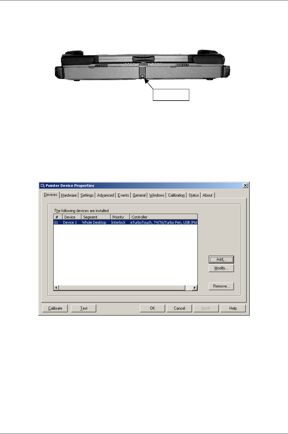
Multiple behavior settings are available for the touchscreen. Your preferences may differ from the default settings for
interacting with screen objects. You can change these settings by:
• Running the touchscreen property sheet from the Start-Programs-UPDD-Settings menu,
• Clicking on “Pointer Device Settings” in the system tray, or
• Running “Pointer Devices” in Windows Control Panel. The following screen will appear.
• Navigate the Settings and Advanced tabs to adjust click responsiveness.
• Select the Events tab to program the mouse event that executes when touching the screen.
• The Windows tab provides double-click settings and a test area to try your new settings.
• Click the Help button if you need more information.
Driver Installation
The driver for your touchscreen is loaded at the factory when you order a Microsoft Windows operating system. If you
need to reload the driver, use the ReVolution Utilities CD included with your unit.
36 02/25/03 ReVolution User Manual 1.00

Calibrate
The ReVolution touchscreen is calibrated at the factory. Run the calibration routine when an alignment problem exists
between the mouse pointer and the stylus contact location on the screen. You can adjust the calibration of the
touchscreen by running the program at Start-Programs-UPDD-Calibrate. Carefully touch the location of the markers
with your stylus to recalibrate the touch screen.
After calibrating the ReVolution touchscreen you can test the alignment by pressing the Test button to view the
tracking accuracy.
ReVolution User Manual 1.00 02/25/03 37

Touch Pad
The built-in touch pad is a PS/2-compatible pointing device that senses movement on its surface; the cursor responds
as you move your finger on the surface of the touch pad. The central location on the palm rest provides optimal
comfort and support.
Touch Pad Basics:
1. Move your finger across the touch pad to move the cursor.
2. Press the left and right buttons located on the bottom edge of the touch pad to select and execute. These two
buttons are similar to the left and right buttons on a mouse. Tapping on the touch pad produces similar results.
Function Left Button Right Button Tap
Execute Click twice quickly Tap twice (at same speed
as double-clicking a mouse
button)
Select Click once Tap once
Drag Click and hold, then use
finger to drag the cursor on
the touch pad
Tap twice (at same speed
as double-clicking a mouse
button), then hold finger to
the touch pad on the
second tap and drag the
cursor.
Access Content Menu Click once
Scroll
Note: Keep your fingers clean and dry when using the touch pad. Also keep the touch pad dry and clean. The touch
pad is sensitive to finger movements. Hence, the lighter the touch, the better the response. Tapping harder will not
increase the touch pad’s responsiveness.
Change the behavior of the touch pad by adjusting the Mouse Properties in the Microsoft Windows Control Panel,
displayed on the following page. For additional touch pad control, load the touch pad driver found on the ReVolution
Utilities CD included with your unit.
38 02/25/03 ReVolution User Manual 1.00
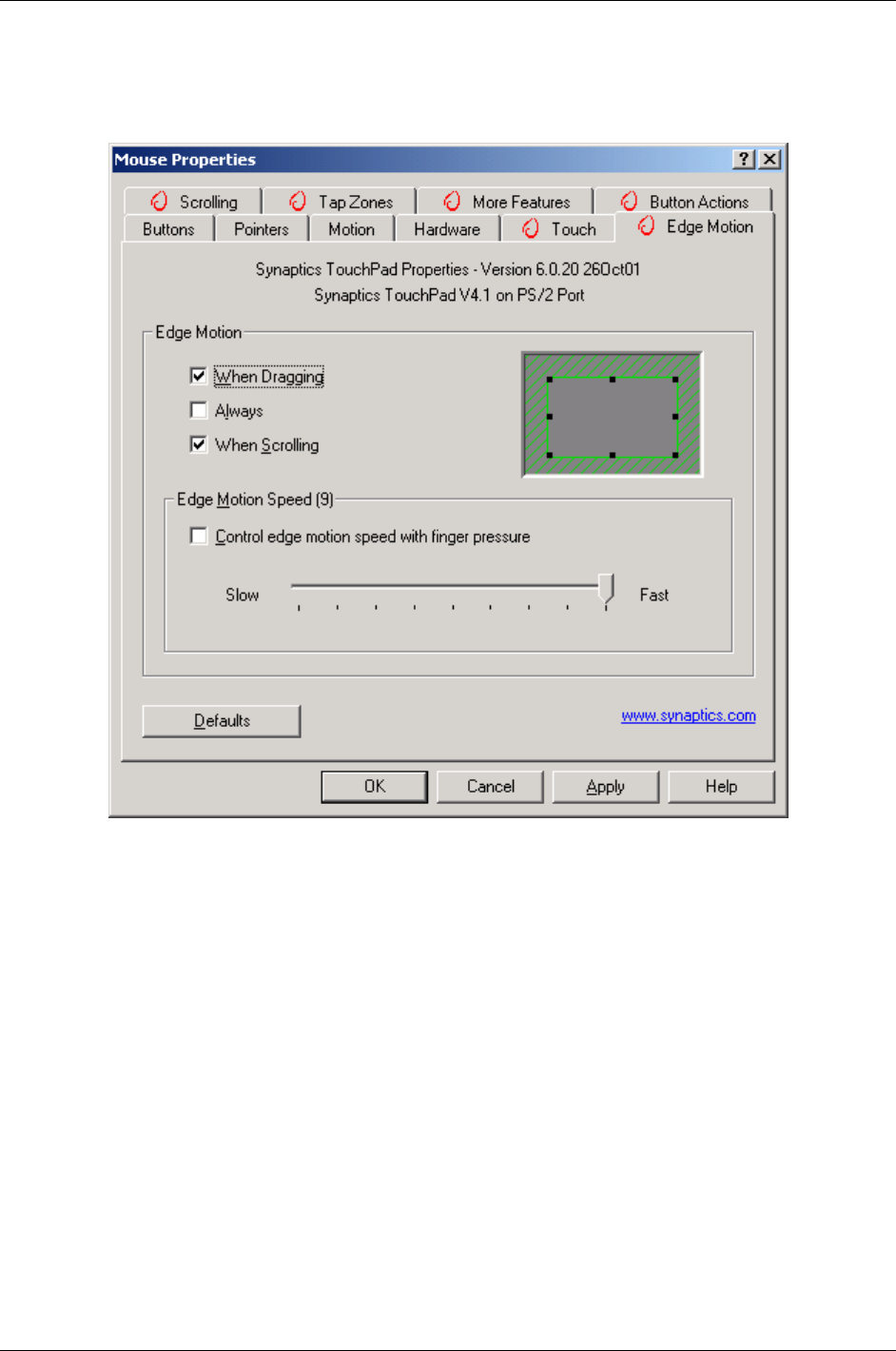
Special touch pad features allow greater control of touch pad usage. Familiarize yourself with these features on this
screen.
USB Ports
Driver Installation
The ReVolution is designed with a USB 2.0 compliant controller that requires an operating system driver to exploit its
capabilities. The driver is preinstalled at the factory and a backup of the driver is on the ReVolution Utilities CD
delivered with your system.
ReVolution User Manual 1.00 02/25/03 39
Video
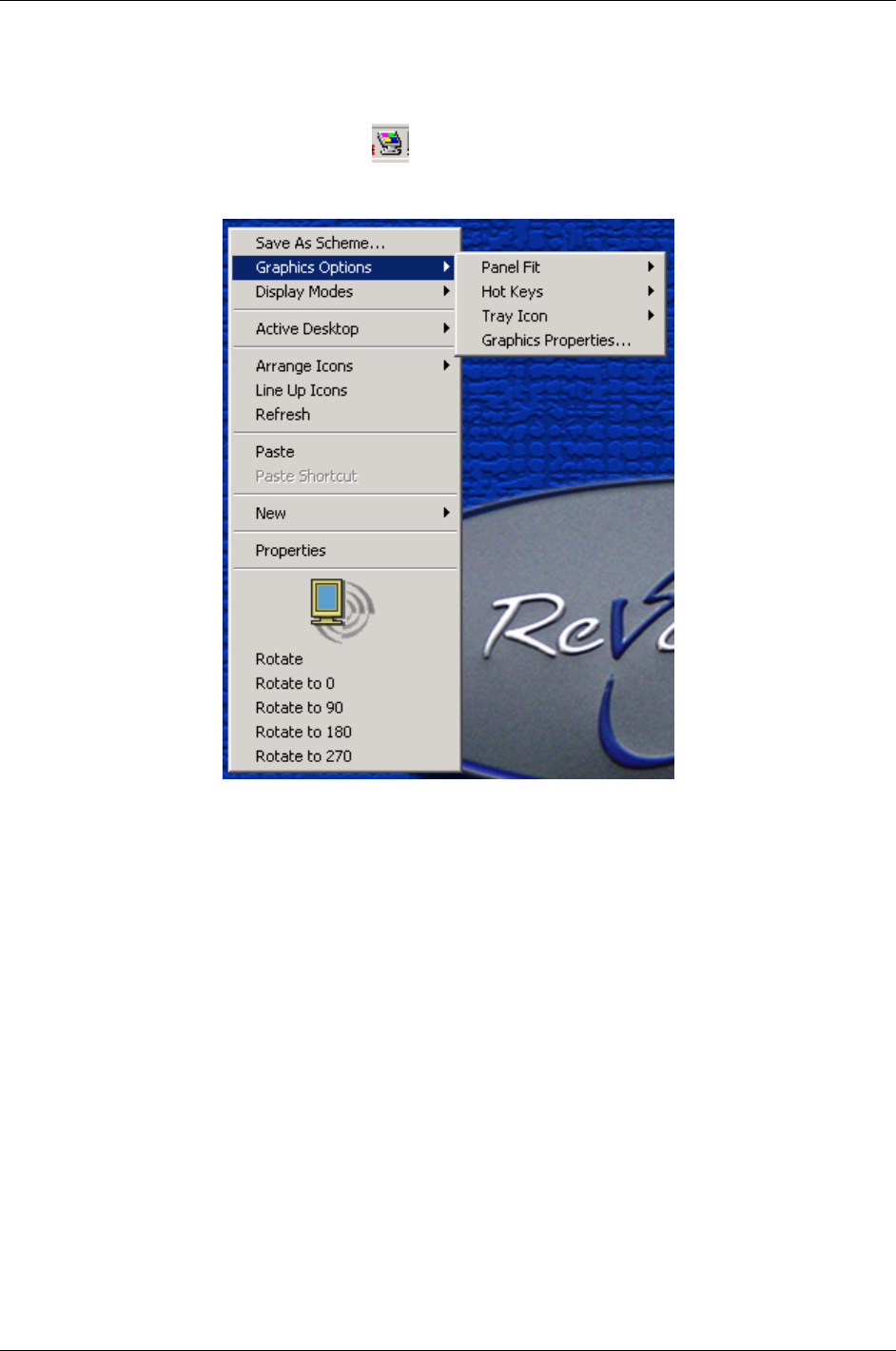
The ReVolution is designed with the Intel i830M grapics and memory ccontroler (GMCH). You can control the video
system through the Microsoft Windows Control Panel. You can also gain quick access to video options by clicking the
Intel Graphics Technology icon in the system tray or by right clicking on the desktop, as follows.
40 02/25/03 ReVolution User Manual 1.00
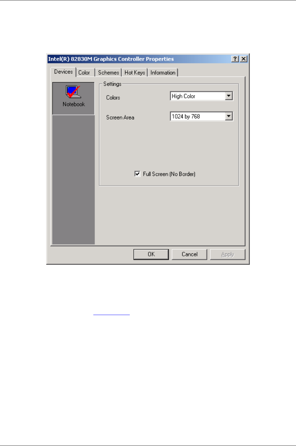
The Graphics Controller property sheet through the Windows Control Panel allows you view and change device color
depth, resolution, color correction, display schemes, and hot keys.
Driver Installation
Browse the ReVolution Utilities CD to locate the video driver installation. Intel frequently updates the graphics drivers
for i830M. Download this driver from www.intel.com.
ReVolution User Manual 1.00 02/25/03 41
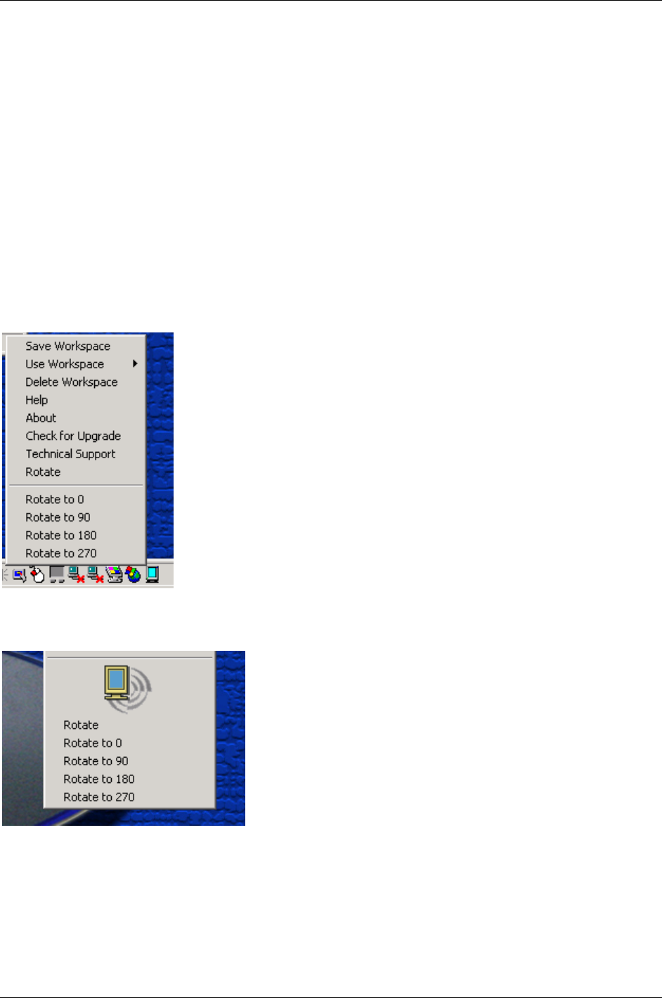
Video Rotation
The ReVolution can change the orientation of the display image in four degrees of rotation. Rotating the screen can
be useful when running the ReVolution in tablet mode, to suit your workspace. The normal orientation when in laptop
mode is zero degrees. You may want to switch to 90 or 270 for a “Portarit” display or simply flip the screen by
setting 180 rotation. There is three ways to change screen rotation. Use the system tray icon, right click on the
desktop, or use the hot keys.
Hot Key Rotation:
To rotate your screen's image press <Control> + <Shift> and hit the <R> key.
Rotate to 0 press <Control> + <Shift> and hit the <0> key.
Rotate to 90 press <Control> + <Shift> and hit the <9> key.
Rotate to 180 press <Control> + <Shift> and hit the <8> key.
Rotate to 270 press <Control> + <Shift> and hit the <7> key.
Task Bar Rotation
Desktop Rotation:
42 02/25/03 ReVolution User Manual 1.00

Wireless - 802.11b (WLAN)
Do not operate the ReVolution in areas sensitive to radio
interference, such as airplanes and hospitals.
There is no means to shut off the Bluetooth and WLAN radios installed in the
system.
The integrated Wireless LAN (WLAN) device in the ReVolution is an 802.11b wireless network card that is attached
to the computer via a mini-PCI slot.
The main characteristics include:
• Operating frequency in the 2.4 GHz band.
• Compliance with WECA Wireless Fidelity (Wi-Fi) testing standard and ability to communicate up the maximum
transfer rate of 11 Mbps.
• Maximum range of about 105 Meters.
This device provides a plug-and-play seamless connectivity to all network resources, and Internet access at up to 11
Mbps. No cables are necessary to run, just an access point. It provides a high-speed connectivity at up to 11 Mbps
over an extended operating range. It automatically falls back to 5.5, 2, and 1 Mbps. It is compliant with IEEE 802.11b
standards which also assures compatibility with other 802.11b compliant devices and networks.
Frequency Range: 2.4 GHz to 2.4835 GHz
Typical outdoor operating range 30 M @ 11 Mbps
50 M @ 5.5 Mbps
100 M @ 2 Mbps
105 M @ 1 Mbps
Modulation Technique: DSSS(Direct Sequence Spread Spectrum) with BPSK
(1Mbps), QPSK (2Mbps), and CKK(5.5 and 11 Mbps)
Channel Support US/Canada: 11 (1 ~ 11)
Major European Country: 13(1 ~ 13)
France: 4(10~13)
Japan: 14(1 ~ 13 or 14th)
Driver
The software for the WLAN allows you to view and set the connection to other 802.11b devices. Run this utility by
navigating to Start-Programs-IEEE 802.11b MiniPCI Utility in Windows 2000 or Windows 98. The following screen will
appear. When running Windows XP go to Device Manager.
ReVolution User Manual 1.00 02/25/03 43
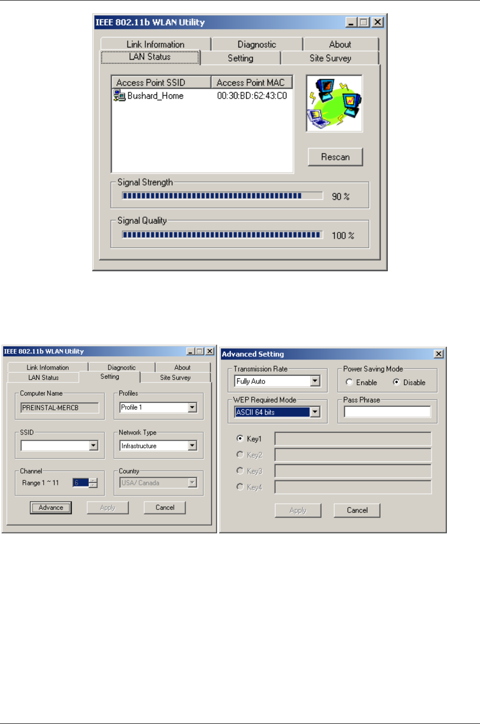
To secure transmissions with an 802.11b device that has WEP enabled, set a pass phrase or key on the Advanced
Setting window.
44 02/25/03 ReVolution User Manual 1.00

Wireless - Bluetooth
Do not operate the ReVolution in areas sensitive to radio
interference, such as airplanes and hospitals. There is no
means to shut off the Bluetooth and WLAN radios installed in the system.
For PAN environments, Bluetooth provides freedom from wired connections. By using this radio-based link,
computers, mobile phones, PDA and other portable handheld devices are able to transmit data to each other or
connect to Internet without a single cable.
While the possibilities are nearly endless for the applications of the technology, some of the current capabilities
include:
• Eliminating the need for wired connections between electronic products and accessories such as a keyboard,
mouse, headsets, printers, other computers;
• Exchanging files, business cards, calendar appointments, etc. with groups of Bluetooth users;
• Transferring and synchronizing files between devices;
• Connecting to localized content services in public areas;
• Functioning as remote controls, keys, tickets and e-cash wallets.
The Bluetooth wireless technology and Wireless LAN (802.11b) are complementary technologies. The Bluetooth
wireless technology is designed to replace cables between cell phones, laptops, and other computing and
communication devices within a 10-meter range. Wireless LAN is wireless Ethernet; it provides an extension or
replacement of wired networks for dozens of computing devices.
Issues do arise with the coexistence of both Bluetooth and Wireless LAN. Any time devices are operated in the same
frequency band, there is the potential for interference which results in a lower bandwidth
This device has a maximum range of about 10 meters, depending on the environment. The maximum data transfer
rate is 1.0Mbps. This is a Class 2 device with a typical Tx power of 0 dBm. The operating frequency range is 2.402
GHz to 2.480 GHz with a channel spacing of 1 MHz.
ReVolution User Manual 1.00 02/25/03 45

Technical Data
ReVolution
Main Specification
Processor Intel Mobile Pentium® III-M 1.06 GHz or higher
Main Battery Lithium Ion battery - 57 Watt, 3.5 hour life (approximate)
BIOS: PhoenixBIOS 4.0, Release 6
RAM: 128 MB SDRAM standard
L2-Cache 512KB
Keyboard: Full-size QWERTY keyboard with 84 keys (USA Standard)
Interfaces: 1x Power Connector with 10-28 VDC, 4.6 Amps
1x Serial Port (COM 1)
2x USB 2.0 Ports
Docking connector
1x RJ11 56K V.90 Modem
1x RJ45 10/100Mbs Ethernet/LAN
Audio phonejacks:
1x MIC-In
1x Line-In
1x Speaker-Out
Integrated: 802.11b WLAN, Bluetooth PAN
Hard Disk
Drives:
40GB primary removable hard drive standard – upgradeable
to 60GB
40GB secondary, optional removable hard drive –
upgradeable to 60MB
Call Technical Support or your Sales Representative for other
available options.
PCMCIA: Card BUS connector provides two open PC Card slots that
accommodate two Type II, or one Type III PCMCIA device.
Graphics
Controller:
Integrated Direct AGP Graphics
Core frequency up to 166 MHz
350 MHz RAM DAC
Video-RAM: 8 to 48 MB of Dynamic Video Memory (shared)
Up to 32 MB with 128 MB RAM; 48 MB with 256 MB RAM
Pointing
Device:
Touch Pad on the keyboard, Touchscreen on the display
Power
specification
10-24 VDC
AC adapter: Input: 90-264 VAC, 50-60 Hz; Output: 12V, 55W
RTC/CMOS
Battery
Rechargeable LIon real-time clock/CMOS battery on main
board. Not user-serviceable.
46 02/25/03 ReVolution User Manual 1.00

Mechanical Specification
Dimensions:
Width
Depth
Height
12.8" (326 mm)
10.25" (261 mm)
2.125" (54 mm)
Weight: 8 lbs. with one battery module installed.
Chassis: Rigid, lightweight magnesium design
Environmental Specifications
Operating temperature –15 C to +50°C
(5 F to 140 °F)
NOTE: Excludes all CD-ROM, DVD and floppy
devices. See device specifications later in
this section.
Storage temperature –20 C to +70 °C
(–4 F to 158 °F )
NOTE: Excludes all CD-ROM, DVD and floppy
devices. See device specifications later in
this section.
Operating humidity 10–88 % relative humidity, non-condensing
Storage humidity 5–95 % relative humidity, non condensing
Shock Mil-Std 810F:
Method: 516.5
Procedures:
I = 40G
IV = 26 drops @ 36”
V = 75G
NOTE: Excludes all CD-ROM, DVD and floppy
devices. See device specifications later in
this section.
Vibration Mil-Std 810F:
Method: 514.5
Procedure I
Category 20 & 24
Blowing Rain IP54/NEMA 3
Sand and Dust NEMA 3
Altitude Operating Up to 15,000 ft. (4,500 m)
Altitude Non-Operating Up to 35,000 ft. (10,668 m)
EMI & Safety FCC Part 15 Class B (ETSI 300 328/1997)
CE Directive Class B (ETSI 301489-17/2002)
UL, EN 60950
ReVolution User Manual 1.00 02/25/03 47

CE-Directives and Standards
CE –Directives
Low Voltage directive
(Electrical Safety) EN 60950
EMC Directive EN 55022
Electrical Safety Standards
U.S.A. UL 60950/2002
Canada CSA 22.2 No. 60950-00
EMC Standards
U.S.A. FCC Part 15.247/2002
48 02/25/03 ReVolution User Manual 1.00

CD-ROM Module
Interface IDE
Temperature range in operation: 5°C to +50°C
in storage: -30°C to +65°C
Humidity 5% - 90% (relative, non-condensing)
Features Read Data 24X CAV max.
Audio Play 8X CAV max.
CD-RW Module
Interface IDE
Temperature range in operation: 5°C to +50°C
in storage: -20°C to +60°C
Humidity 10% - 80% (relative, non-condensing)
Features Write 8X max.
Read 24X max.
DVD Module
Interface IDE
Temperature range in operation: 5°C to +50°C
in storage: -30°C to +65°C
Humidity 5% - 90% (relative, non-condensing)
Features DVD-ROM 24X CAV max.
CD 8X CAV max.
DVD/CD-RW Module
Interface IDE
Temperature range in operation: 5°C to +50°C
in storage: -20°C to +60°C
Humidity 10% - 80% (relative, non-condensing)
Features Read:
DVD-ROM 8X CAV max.
CD-ROM 24X CAV max.
Write:
CD-R 8X CLV
CD-RW 4X CLV
High Speed CD-RW 8X CLV
ReVolution User Manual 1.00 02/25/03 49

Floppy Disk Drive Module
Interface TTL
Temperature range in operation: 5°C to +50°C
in storage: -40°C to +60°C
Humidity 20% - 80% (relative, non-condensing)
FDD: 3.5" 1.44Mb Formatted
Lithium Ion Battery Pack
Interface SMBUS VI.0
Temperature range Operating: 0° to +45°C charging
-20° to +60°C discharging
Service Life 300 Cycles typ.
Typical Capacity 8000mAH@.2C
Nominal Voltage 7.40V
Remaining Capacity LEDs:
Green (Three) 76-100% remaining
Green (Two) 51-75% remaining
Green (One) 26-50% remaining
Red 0-25%
50 02/25/03 ReVolution User Manual 1.00
Technical Appendices
The following tables show the connector pin-out assignments for the external connections of the ReVolution
computer. Active low signals are indicated by a minus sign. Refer to the “ReVolution at a Glance” section for
locations.
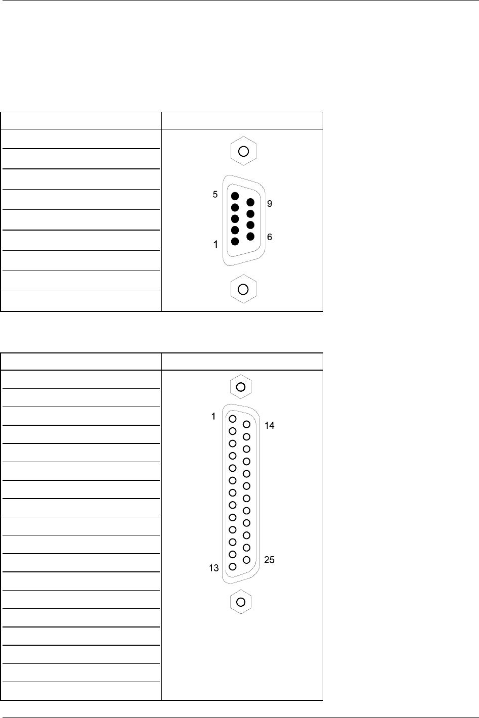
RS232 Serial Port (COM A)
Pin Signal name 9-pin SUB D-plug
1 DCD (Data Carrier Detect)
2 RXD (Receive Data)
3 TXD (Transmit Data)
4 DTR (Data Terminal Ready)
5 GND (Signal Ground)
6 DSR (Data Set Ready)
7 RTS (Request to Send)
8 CTS (Clear to Send)
9 RI (Ring Indicator)
Parallel Port (I/O Stick Option Only)
Pin Signal name 25-pin SUB D-socket
1 –STROBE
2 DATA0
3 DATA1
4 DATA2
5 DATA3
6 DATA4
7 DATA5
8 DATA6
9 DATA7
10 –ACKN
11 BUSY
12 PE
13 SELECT
14 –AUTOFD
15 –ERROR
16 –INIT
17 –SLCTIN
18–25 GND
ReVolution User Manual 1.00 02/25/03 51
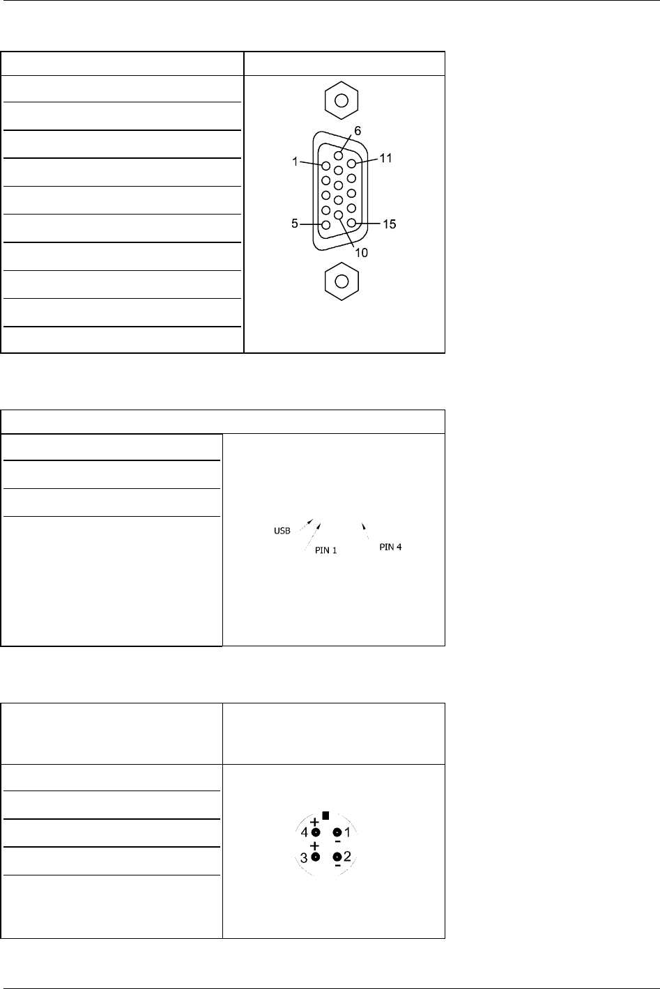
Analog Monitor (VGA-Output, I/O Stick Option Only)
Pin Signal name 15-pin SUB D-socket
1 red
2 green
3 blue
4, 5 4 is NC, 5 is GND
6–8 GND
9 not connected
10–12 10-GND, 11-NC, 12-DDC Data
13 HSYNC
14 VSYNC
15 DDC Clock
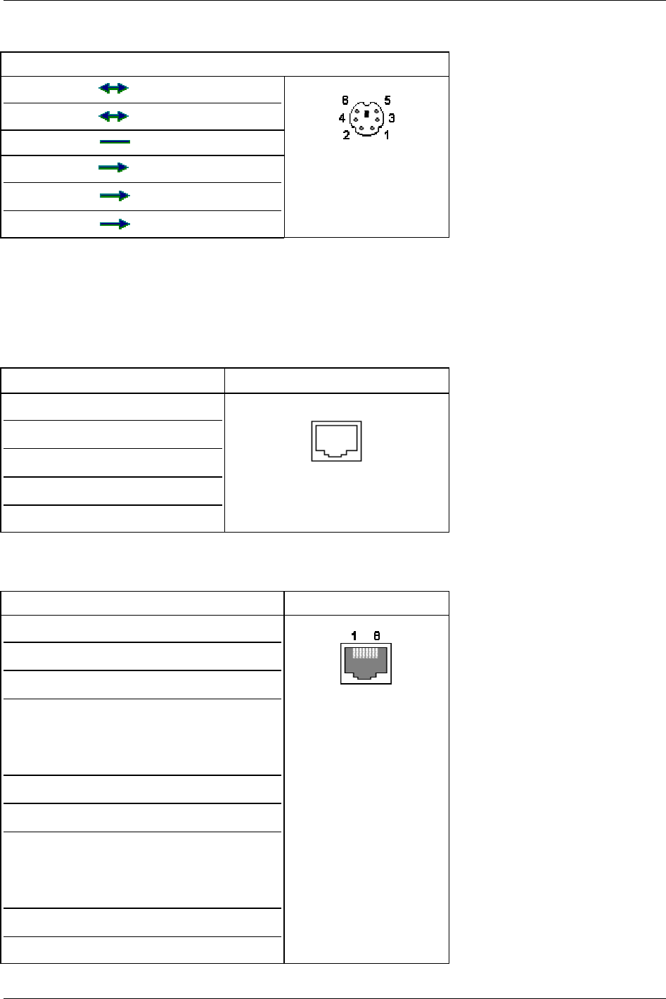
USB 2.0 Ports
Pin Signal name USB
1 +5 Volts
2 P-
3 P+
4 GND
Power Supply Connector
Pin Signal name 4-pin Female socket
(Looking into socket on back
interface panel))
1 Ground
2 Ground
DC Input(+10 to +28 Volts DC)
DC Input(+10 to +28 Volts DC)
3
4
52 02/25/03 ReVolution User Manual 1.00
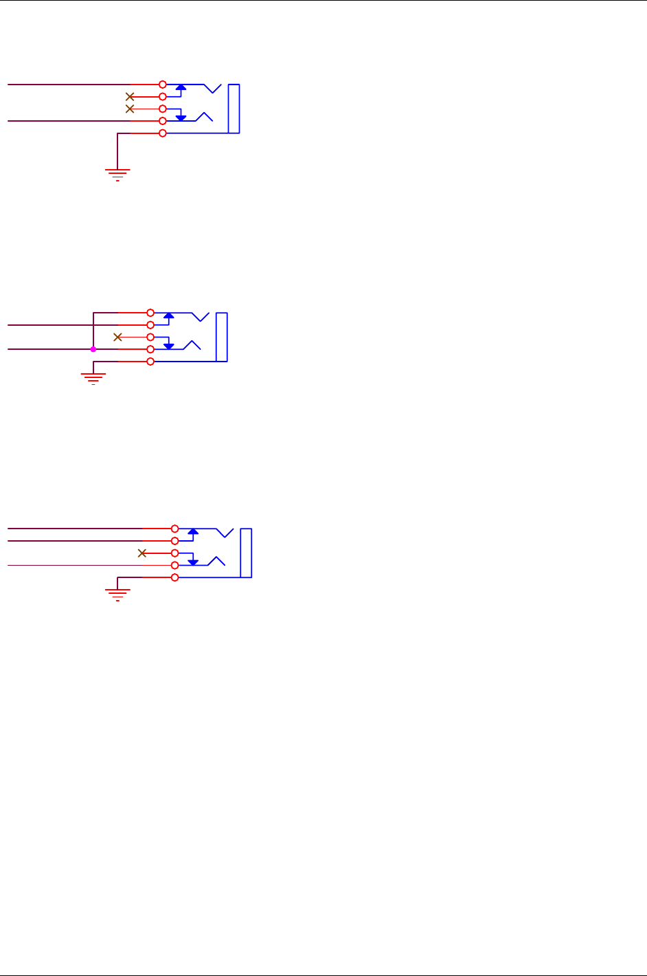
PS/2 Keyboard/Mouse Connector (I/O Stick Option Only)
Pin Name Dir. Description
1 DATA Mouse Data
2 DATA Keyboard Data
3 GND Ground
4 VCC Power , +5 VDC
5 CLK Mouse Clock
6 CLK Keyboard Clock
This illustrates the pin-out of the external PS/2 Keyboard/Mouse connector. This connection is “hot pluggable” and
interchangeable between the external keyboard and the external mouse. Hot pluggable means you may connect
either the external keyboard or external mouse while the computer power is on.
RJ-11 Modem Port
Pin Name
1 Not Connected
2 TIP
3 RING
4 Not Connected
RJ-45 LAN Port
Pin Name Description RJ-45 LAN Port
1 TX+ Transmit Data+
2 TX- Transmit Data-
3 RX+ Receive Data+
4 Not Connected Pin 4 is shorted to Pin
5 then AC coupled to
ground through a 75
Ohm resistor
5 Not Connected See Above
6 RX- Receive Data-
7 Not Connected Pin 7 is shorted to Pin
8 then AC coupled to
ground through a 75
Ohm resistor
8 Not Connected See Above
ReVolution User Manual 1.00 02/25/03 53
Line-In
LINE IN RIGHT
LINE IN LEFT
5
4
3
2
1
AGND_A
AGND_A
AGND_A
MIC-In
MIC
MUTE
5
4
3
2
1
Speakers
MUTE_S
SPEAKER RIGHT
SPEAKER RIGHTSPEAKER RIGHT
5
4
3
2
1
54 02/25/03 ReVolution User Manual 1.00

System Hardware Assignments
The ReVolution, like all computers based on standard IBM-compatible personal computer architecture, contains a set
of user hardware- and software-configurable resources. The system uses some of these resources for various
standard and optional features. The user can modify others.
This section describes the standard system resources, their use and assignment status.
The following table of Interrupt ReQuests (IRQs) are assigned by the BIOS. Plug-and-play operating systems
(Windows 98/2000/XP) may change the IRQ assignments.
Table of IRQ Assignment by BIOS
IRQ Number Use Type Status
0 Timer ISA Permanent Assignment
1 Keyboard ISA Permanent Assignment
2 Programmable Interrupt
Controller
ISA Permanent Assignment
3 COM Port B (2) ISA BIOS enable/disable
4 COM Port A (1) ISA BIOS enable/disable
5 PNP/PCI
6 Floppy Disk ISA Permanent Assignment, if installed
7 LPT1 BIOS Adjustable
8 Real Time Clock ISA Permanent Assignment
9 ACPI EC ISA PNP/PCI Assignment
10 PNP/PCI
11 PNP/PCI
12 Mouse ISA BIOS enable/disable
13 Math Coprocessor ISA Permanent Assignment
14 IDE Controller ISA PCI/PNP assignment
15
DMA Channel Table
DMA Channel Use Status
0 Unused Available To User
1 Unused Available To User
2 Floppy Disk Permanent Assignment
3 ECP Parallel Port BIOS adjustable
4 DMA Controller Permanent Assignment
5 Unused Available To User
6 Unused Available To User
7 Unused Available To User
ReVolution User Manual 1.00 02/25/03 55
Embedded Controller
The Embedded Controller (EC) in the ReVolution supervises its “power state” by monitoring incoming power levels
and temperature, making decisions for safe operation. The EC also interacts with the system BIOS and informs the
APM manager with power-related messages. When a fault condition occurs, the EC will change the power state and
indicate the fault by flashing a series of codes on the power LED:
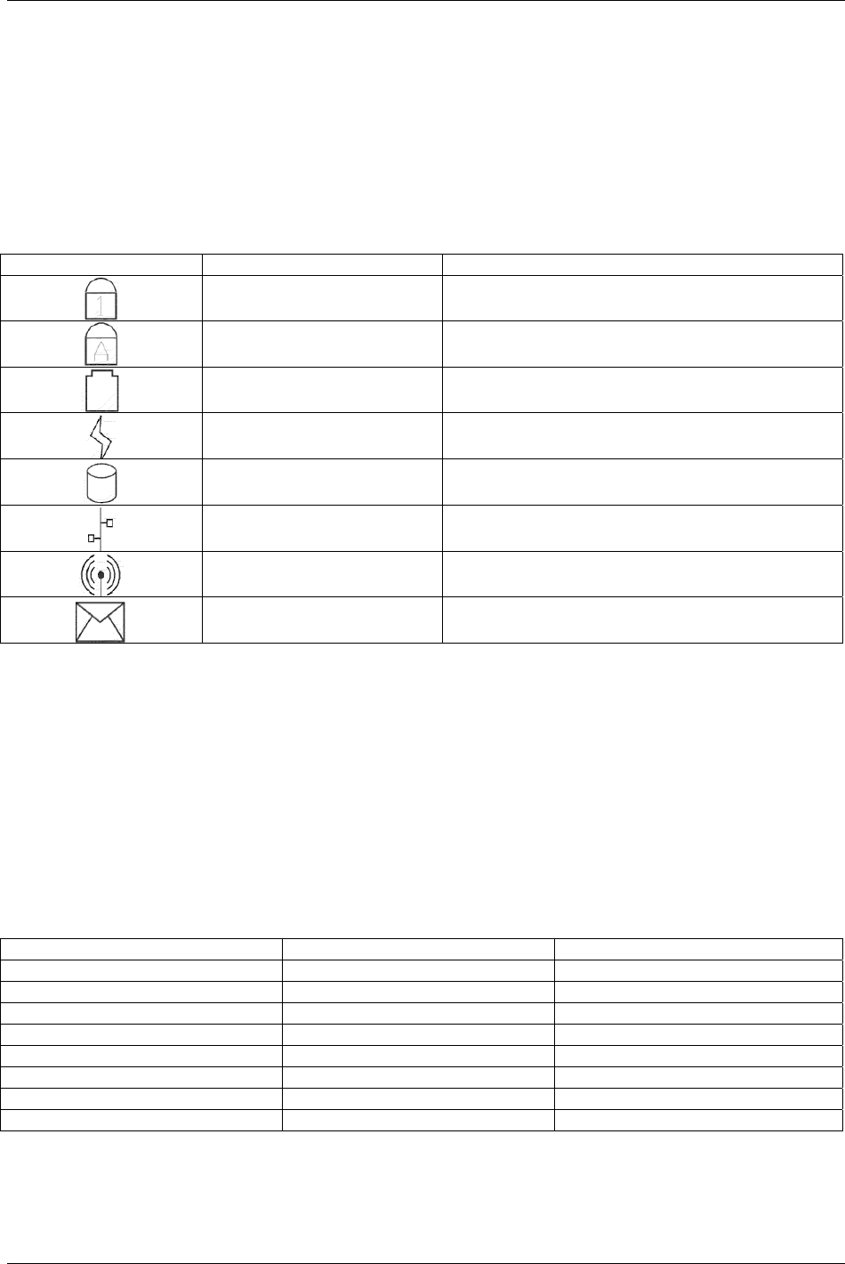
Embedded Controller LEDs
Refer to the “ReVolution at a Glance” section for LED locations.
Symbol Name Purpose
NumLock Indicates NumLock state. LED is on when NumLock
is active.
Caps Lock Indicates capital letter state. LED is on when Caps
Lock is active.
Battery Indicator Indicates battery status
Power Indicates AC power attached
Hard Disk Drive Activity Indicates when hard drive is accessed.
LAN Activity Indicates embedded LAN activity.
Wireless Activity Future Use
Mail Future Use
You must clear the active fault before the EC will continue operation. The EC is continuously on when power is
applied to the ReVolution. It is field-upgradeable.
The EC will perform a power-down override, which forces the ReVolution to turn off, when a user presses the power
on/off button continually for 4 seconds.
Note: The Embedded Controller is active whenever there is a DC power source (external or battery) present, even
with ReVolution power off. If the ReVolution is stored with one battery installed, the EC will discharge a fully charged
battery in approximately 27 days. Kontron recommends that the ReVolution be stored for extended periods with no
battery installed.
Power and Battery Indicators
Power State Power LED Battery Indicator LED
OFF OFF OFF
On, Charging ON Slow Blink
Low Battery OFF Fast Blink
Running on battery OFF ON
Running on AC not charging ON OFF
Battery Malfunction Fast Blink Fast Blink
Sleep mode battery Slow Blink OFF
Sleep mode AC OFF Slow Blink
Slow blink is defined as - 0.5 Hz, 50% duty cycle, i.e. ON for one second, OFF for one second
Fast blink is defined as - 1 Hz, 50 % duty cycle, i.e. On for 500 ms, OFF for 500 ms
56 02/25/03 ReVolution User Manual 1.00

Phoenix BIOS Setup
Use the Phoenix BIOS Setup program for:
• Setting system time and date.
• Installing new drives for hard disks and floppy disks.
• Enhancing system performance by controlling advanced features such as shadow memory and cache
memory.
To start the Phoenix BIOS Setup utility:
1. Turn on or reboot your system.
2. Press the ESC key when ReVolution splash screen appears.
3. PhoenixBIOS displays this message: Press <F2> to enter SETUP
4. Pressing <F2> displays the Main Menu.
Incorrect settings can cause your system to malfunction.
Navigating the Setup Menus
The Menu Bar at the top of the window lists these selections:
Main Use this menu for basic system configuration.
Advanced Use this menu to set the Advanced Features available on your system's chipset.
Security Use this menu to set User and Supervisor Passwords and the Backup and Virus-Check reminders.
Power Use this menu to configure Power-Management features.
Exit Exits the current menu.
Use the left/right arrow keys to make a selection.
Legend Bar
Use the keys listed in the legend bar on the bottom of the screen to make your selections or exit the current menu.
The chart on the following page describes the legend keys and their alternates:
Key Function
<F1> or <Alt-H> General Help window (See below).
<Esc> Exit this menu.
↔ Left or right arrow keys Select a different menu.
↕ Up or down arrow keys Move cursor up and down.
<Tab> or <Shift-Tab> Cycle cursor up and down.
<Home> or <End> Move cursor to top or bottom of window.
<PgUp> or <PgDn> Move cursor to next or previous page.
<F5> or <-> Select the Previous Value for the field.
<F6> or <+> or <Space> Select the Next Value for the field.
<F9> Load the Default Configuration values for this menu.
<F10> Load the Previous Configuration values for this menu.
<Enter> Execute Command or Select P Submenu.
<Alt-R> Refresh screen.
To select an item:
• Use the arrow keys to move the cursor to the field you want.
• Use the plus-and-minus value keys to select a value for that field. The Save Values commands in the Exit Menu
save the values currently displayed in all the menus.
To display a sub menu:
• Use the arrow keys to move the cursor to the sub menu you want.
• Press <Enter>. A pointer (_) marks all sub menus.
ReVolution User Manual 1.00 02/25/03 57

Field Help Window
The Help window on the right side of each menu displays the help text for the currently selected field. It updates as
you move the cursor to each field.
General Help Window
Advanced Hard Disk Features
If Advanced Hard Disk Features are installed, select one of the Master or Slave sub-menus on the Main Menu.
Use the legend keys listed on the bottom to make your selections and exit to the Main Menu.
Use the chart on the following page to configure the hard disk drive with Advanced Hard Disk Features:
58 02/25/03 ReVolution User Manual 1.00

Advanced Hard Disk Features
Feature Options Description
Type None
User
Auto (Default)
IDE Removable
CD-ROM
ATAPI Removable
None = Autotyping is not able to
supply the drive type, or end user has
selected None, disabling any drive
that may be installed.
User = You supply the hard-disk
drive information in the following
fields.
Auto = Autotyping, the drive itself
supplies the information.
IDE Removable = Removable disk
drive
CD-ROM = CD-ROM drive.
ATAPI Removable = Removable
disk drive.
Cylinders 1 to 65,536 Number of cylinders.
Heads 1 to 16 Number of read/write heads.
Sectors
Multi-Sector Transfers
Disabled
Standard
2 sectors
4 sectors
8 sectors
16 sectors
Any selection except Disabled
determines the number of sectors
transferred per block. Standard is 1
sector per block.
LBA Mode Control Enabled
Disabled
Enabling LBA causes Logical Block
Addressing to be used in place of
Cylinders, Heads, & Sectors.
32-Bit I/O
Enabled
Disabled (Default)
This setting enables or disables 32-bit
IDE data transfers.
Transfer Mode
Standard
Fast PIO 1
Fast PIO 2
Fast PIO 3
Fast PIO 4
OR
Standard
Fast DMA A
Fast DMA B
Fast DMA F
Selects the method for transferring
the data between the hard disk and
system memory. The Setup menu
only lists those options supported by
the drive and platform.
Ultra DMA Mode Disabled
Mode 0
Mode 1
Mode 2
Mode 3
Mode 4
Mode 5
Selects the Ultra DMA mode used for
moving data to/from the drive.
Autotype the drive to select the
optimum transfer mode.
ReVolution User Manual 1.00 02/25/03 59

Memory Cache
Enabling cache saves time for the CPU by holding data most recently accessed in regular memory (dynamic RAM or
DRAM) in a special storage area of static RAM (SRAM), which is faster. Before accessing regular memory, the CPU
first accesses the cache. If it does not find the data it is looking for there, it accesses regular memory.
Selecting Memory Cache from the Main Menu displays a menu like the one shown here. The actual features
displayed depend on your system's hardware.
Feature Options Description
Memory Cache Enabled (Default)
Disabled
Sets the state of the memory cache.
Cache System BIOS area Uncached
Write Protect (Default)
Controls caching of BIOS system.
Cache Video BIOS area Uncached
Write Protect (Default)
Controls caching of video BIOS area.
Cache Base 0-512K: Uncached
Write Through
Write Protect
Write Back (Default)
Controls caching of 512k base
memory
Cache Base 512k-640k: Uncached
Write Through
Write Protect
Write Back (Default)
Controls caching of 512k – 640k base
memory
Cache Extended Memory Area: Uncached
Write Through
Write Protect
Write Back (Default)
Controls caching of system memory
above one megabyte
Cache segments, e.g., E800-EFFF Enabled
Disabled (Default)
Write Through
Write Protect
Write Back
Controls caching of individual
segments of memory usually reserved
for shadowing system or option
ROMs
WARNING: Incorrect settings can cause your system to malfunction.
Boot Features Menu
Select Boot from the menu bar on the Main Menu.
Use the legend keys to make your selections and exit to the Main Menu.
Use the following chart to select your boot options.
Feature Options Description
Boot-time Diagnostic Screen: Enabled
Disabled (Default)
Display the diagnostic screen during
boot.
Quickboot Mode: Enabled (Default)
Disabled
Allows the system to skip certain
tests while booting. This will
decrease the time to boot the system.
The BIOS attempts to load the operating system from the disk drives in the sequence selected here. The topmost
item is the first boot device that BIOS will attempt to boot an operating system. If the device is not bootable the BIOS
will move to the next device until a bootable device is found. If no devices are found to be bootable then the BIOS will
post an error message.
60 02/25/03 ReVolution User Manual 1.00

Advanced Menu
Select Advanced from the menu bar on the Main Menu.
Use the legend keys to make your selections and exit to the Main Menu.
Use the following chart to configure the keyboard features:
Feature Options Description
Installed O/S Other
Win95
Win98 (Default)
WinME
Win2000
Select the operating system installed
on your system that you will use most
often.
NOTE: An incorrect setting can
cause some operating systems to
display unexpected behavior.
Reset Configuration Data: No (Default)
Yes
Select “Yes” if you want to clear the
Extended System Configuration Data
(ESCD) area.
Large Disk Access Mode: Other
DOS (Default)
UNIX, Novell Netware, or other
operating systems, select ‘Other’. If
you are installing new software and
the drive fails, change this selection
and try again. Different operating
systems require different
representations of drive geometries.
Local Bus IDE adapter: Disabled (Default)
Primary (Default)
Enable the integrated local bus IDE
adapter
OEM Platform Advanced Menu The items in this menu will allow the
user to:
1) Test Mobile features of the
Almador-m Chipset
2) Alter the Reference board
environment.
Advanced Chipset Control
I/O Device Configuration
Keyboard Features
Legacy USB Support Enabled (Default)
Disabled
Enable support for Legacy Universal
Serial Bus.
OEM Platform Advanced Memory Menu
Feature Options Description
Platform Power Management Sub-
Menu
These items will control the
various CPU and Chipset Power
Management Features of this
platform
ACPI Table/Features Control Sub
Menu
These items will control:
1) Which ACPI Tables will be
include in the RSDT Entry
Table Field.
2) The values stored in specific
ACPI Table Fields.
3) The Enabling of Specific
ACPI Features.
Integrated Devise Control Sub-
Menu
These items determine whether
the integrated PCI Devices will
be enabled in PCI Config. Space
ATA 66/ATA 100 Support Enabled
Disabled
This item allows IDE drives to be
set above ATA 33 if the drive
supports that speed.
ReVolution User Manual 1.00 02/25/03 61

Integrated Device Control Sub-Menu
Feature Options Description
USB – Device 29 Disabled
Enabled (Default)
Enable or Disable all ICH3 USB
1.1 Devices by setting item to the
desired value.
USB – Device 29, Function 1 Disabled
Enabled (Default)
Enable or Disable all ICH3 USB
1.1 Devices by setting item to the
desired value.
USB – Device 29, Function 2 Disabled
Enabled (Default)
Enable or Disable all ICH3 USB
1.1 Devices by setting item to the
desired value.
AC97 – Device 31, Function 5 Disabled
Enabled (Default)
Enable or Disable the AC97 Audio
Device if present. This Setup Item
will have no effect if an AC97
Audio MDC is not present.
Advanced Chipset Control Menu
Feature Options Description
IGD Boot Type VBIOS Default (Default)
CRT
LCD
CRT_LCD
Select the Video Display that the
Internal Graphics Device will
make active during the POST:
1) VBIOS Default
2) CRT
3) LCD
4) CRT_LCD
Selecting “VBIOS Default” will
allow the VBIOS to choose the
Video Display to enable.
IGD – LCD Panel Type 800x600 LVDS
1024x768 LVDS (Default)
Select the LCD Panel used by the
Internal Graphics Device by
selecting the appropriate setup
item. The first item is Panel 1, the
last item is Panel 16. Some
Panels are not numbered due to
size constraints.
NOTE: SVGA screen requires
change to 800x600 LVDS.
Default Primary Video AGP (Default)
PCI
Select PCI to use a PCI video
card for the boot display device.
Select AGP to use an AGP video
card for the boot display device.
Graphics Aperture 32MB
64MB (Default)
128MB
256MB
Select the size of the Graphics
Aperture for the AGP video
device.
Enable Memory Gap Disable (Default)
Extended
Free RAM Address space for use
with an option card starting at
15MB.
62 02/25/03 ReVolution User Manual 1.00

I/O Device Configuration Menu
The CPU communicates with external devices such as printers through devices called Input/Output (I/O) ports such
as serial and parallel ports. These I/O devices require the use of system resources such as I/O addresses and
interrupt lines. If these devices are Plug and Play, either the BIOS can allocate the devices during POST, or the
operating system can do it.
If the I/O devices are not Plug and Play, they may require manually setting them in Setup. On some systems, the
chipset manages the communication devices. Other systems have, instead, a separate I/O chip on the motherboard
for configuring and managing these devices.
Many systems allow you to control the configuration settings for the I/O ports.
Select I/O Device Configuration on the Advanced Menu to display this menu and specify how you want to configure
these I/O Devices:
Use the legend keys to make your selections and exit to the Main Menu.
Use the following chart to configure the Input/Output settings:
Feature Options Description
Serial port A:
Serial port B:
Disabled
Enabled (Default)
Auto
OS Controlled
Disabled turns off the port.
Enabled requires you to enter the base
Input/Output address
and the Interrupt number on the next
line.
Auto makes the BIOS configure the
port automatically during
POST.
OS Controlled lets the PnP Operating
System (such as
Windows 95) configure the port after
POST.
Parallel Port: Disabled
Enabled (Default)
Auto
OS Controlled
Disabled turns off the port.
Enabled requires you to enter the base
Input/Output address
and the Interrupt number below.
Auto makes the BIOS auto configure
the port during POST.
OS Controlled lets the PnP Operating
System (such as
Windows 95) configure the port after
POST.
Mode Output only
Bi-directional
ECP (Default)
EPP & ECP
Output only is standard one-way
protocol for a parallel
device.
Bi-directional uses two-way protocol of
an Extended
Capabilities Port (ECP).
Floppy Disk Controller Disabled
Enabled
Auto (Default)
Enables the on-board legacy diskette
controller.
Disabled turns off all legacy diskette
drives.
Auto select per BIOS or OS
Use this menu to specify how the I/O (Input and Output) ports are configured:
• Manually by you.
• Automatically by the BIOS during POST
• Automatically by a PnP Operating System such as Windows 95 after the Operating System boots.
Warning: If you choose the same I/O address or Interrupt for more than one port, the menu displays an asterisk (*) at
the conflicting settings. It also displays this message at the bottom of the menu:
* Indicates a DMA, Interrupt, I/O, or memory resource conflict with another device.
Resolve the conflict by selecting another settings for the devices.
ReVolution User Manual 1.00 02/25/03 63

Keyboard Features
Select Keyboard from the menu bar on the Main Menu.
Use the legend keys to make your selections and exit to the Main Menu.
Use the following chart to configure the keyboard features:
Feature Options Description
Numlock
Auto
On
Off (Default)
On or Off turns NumLock on or off
at bootup. Auto turns NumLock on if
it finds a numeric key pad.
Key Click
Enabled
Disabled (Default)
Enables key click.
Keyboard auto-repeat rate
2/sec
6/sec
10/sec
13.3/sec
21.8/sec
26.7/sec
30/sec (Default)
Sets the number of times per second
to repeat a keystroke when you hold
the key down.
Keyboard auto-lag delay
¼ sec
½ sec (Default)
¾ sec
1 sec
Sets the delay time after the key is
held down before it begins to repeat
the keystroke.
Security Menu
Select Security from the menu bar on the Main Menu.
Use the legend keys to make your selections and exit to the Main Menu.
Enabling "Supervisor Password" requires a password for entering Setup. The passwords are not case sensitive.
Pressing <Enter> at either Set Supervisor Password or Set User Password displays a dialog box like this:
Set Password
Enter password: [ ]
Confirm password: [ ]
Enter: Accept
Type the password and press <Enter>. Repeat.
Note: In some systems, the User and Supervisor passwords are related; you cannot have a User password without
first creating a Supervisor password. In other systems, you can create and use them independently.
Use the following chart to configure the system-security and anti-virus options.
Feature Options Description
Set Supervisor Password Up to seven alphanumeric
characters
Pressing <Enter> displays dialog box for entering
the supervisor password. In related systems, this
password gives full access to Setup menus.
Set User Password Up to seven alphanumeric
characters
Pressing <Enter> displays the dialog box for entering
the user password. In related systems, this password
gives restricted access to SETUP menus.
Password on Boot Enabled
Disabled
Enabled requires a password on boot. Requires prior
setting of the Supervisor password. If supervisor
password is set and this option disabled, BIOS
assumes user is booting.
Diskette Access Enabled
Disabled
Enabled requires a password to boot from or access
the floppy disk.
64 02/25/03 ReVolution User Manual 1.00

Boot Menu
Select Boot from the menu bar on the Main Menu.
Use this menu to arrange to specify the priority of the devices from which the BIOS will attempt to boot the Operating
System. The BIOS will attempt first to boot from the CD-ROM drive (the only Removable Device listed). Failing that, it
will attempt to boot from the Primary Master hard disk, and so on down the list.
Removable Devices, Hard Drive, and Network Boot are the generic types of devices on your system from which
you can boot an operating system. You may have more than one device of each type. If so, the generic type is
marked with a plus or minus sign. Use the <Enter> key to expand or collapse the devices marked with <+> or <->.
Press <Ctrl+Enter> to expand all such devices.
Note: Floppy drives are not managed on this menu as part of Removable Devices. To change a device’s priority on
the list, first select it with the up-or-down arrows, and move it up or down using the <+> and <-> keys. Pressing <n>
moves a device between the Removable Devices and Hard Drive. Pressing <Shift+1> enables or disables a device.
Feature Options Description
Removable Devices Legacy Floppy Drives Keys used to view or configure
devices
Hard Drive Toshiba MK6412MAT-(PM)
Bootable Add - Cards
CD-ROM Drive
Exit Menu
Select Exit from the menu bar on the Main Menu.
The following sections describe each of the options on this menu. Note that <Esc> does not exit this menu. You must
select one of the items from the menu or menu bar to exit.
Exit Saving Values
After making your selections on the Setup menus, always select either "Exit Saving Value" or "Save Changes." Both
procedures store the selections displayed in the menus in CMOS (short for "battery-backed CMOS RAM") a special
section of memory that stays on after you turn your system off. The next time you boot your computer, the BIOS
configures your system according to the Setup selections stored in CMOS.
After you save your selections, the program displays this message: Values have been saved to CMOS!
Press <space> to continue
If you attempt to exit without saving, the program asks if you want to save before exiting.
During bootup, PhoenixBIOS attempts to load the values saved in CMOS. If those values cause the system boot to
fail, reboot and press <F2> to enter Setup. In Setup, you can get the Default Values (as described below) or try to
change the selections that caused the boot to fail.
Exit Discarding Changes
Use this option to exit Setup without storing in CMOS any new selections you may have made. The selections
previously in effect remain in effect.
ReVolution User Manual 1.00 02/25/03 65

Load Setup Defaults
To display the default values for all the Setup menus, select "Load Setup Defaults" from the Main Menu. The program
displays this message:
ROM Default values have been loaded!
Press <space> to continue
If, during bootup, the BIOS program detects a problem in the integrity of values stored in CMOS, it displays these
messages:
System CMOS checksum bad - run SETUP
Press <F1> to resume, <F2> to Setup
The CMOS values have been corrupted or modified incorrectly, perhaps by an application program that changes data
stored in CMOS. Press <F1> to resume the boot or <F2> to run Setup with the ROM default
values already loaded into the menus. You can make other changes before saving the values to CMOS.
Discard Changes
If, during a Setup Session, you change your mind about changes you have made and have not yet saved the values
to CMOS, you can restore the values you previously saved to CMOS. Selecting “Discard Changes” on the Exit menu
updates all the selections and displays this message:
CMOS values have been loaded!
Press <space> to continue
Save Changes
Selecting “Save Changes” saves all the selections without exiting Setup. You can return to the other menus if you
want to review and change your selections.
66 02/25/03 ReVolution User Manual 1.00

BIOS Messages
The following is a list of the messages that the BIOS can display. Most of them occur during POST. Some of them
display information about a hardware device, e.g., the amount of memory installed. Others may indicate a problem
with a device, such as the way it has been configured.
Following the list are explanations of the messages and remedies for reported problems. *If your system displays one
of the messages marked below with an asterisk (*), write down the message and contact Kontron Technical Support.
If your system fails after you make changes in the Setup menus, reset the computer, enter Setup and install Setup
defaults or correct the error.
0200 Failure Fixed Disk
Fixed disk is not working or not configured properly. Check to see if fixed disk is attached properly. Run Setup.
Find out if the fixed-disk type is correctly identified.
0210 Stuck key
Stuck key on keyboard.
0211 Keyboard error
Keyboard not working.
*0212 Keyboard Controller Failed
Keyboard controller failed test. May require replacing keyboard controller.
0213 Keyboard locked - Unlock key switch
Unlock the system to proceed.
0220 Monitor type does not match CMOS - Run SETUP
Monitor type not correctly identified in Setup
*0230 Shadow Ram Failed at offset: nnnn
Shadow RAM failed at offset nnnn of the 64k block at which the error was detected.
*0231 System RAM Failed at offset: nnnn
System RAM failed at offset nnnn of in the 64k block at which the error was detected.
*0232 Extended RAM Failed at offset: nnnn Extended memory not working or not configured properly
at offset nnnn.
0250 System battery is dead - Replace and run SETUP
The CMOS clock battery indicator shows the battery is dead. Replace the battery and run Setup to reconfigure the
system. Note: ReVolution’s CMOS battery is rechargeable and should never need replacement.
0251 System CMOS checksum bad - Default configuration used
System CMOS has been corrupted or modified incorrectly, perhaps by an application program that changes data
stored in CMOS. The BIOS installed Default Setup Values. If you do not want these values, enter Setup and enter
your own values. If the error persists, check the system battery or contact KMC.
*0260 System timer error
The timer test failed. Requires repair of system board.
*0270 Real time clock error
Real-Time Clock fails BIOS hardware test. May require board repair.
0271 Check date and time settings
BIOS found date or time out of range and reset the Real-Time Clock. May require setting legal date (1991- 2099).
0280 Previous boot incomplete - Default configuration used
ReVolution User Manual 1.00 02/25/03 67

Previous POST did not complete successfully. POST loads default values and offers to run Setup. If the failure was
caused by incorrect values and they are not corrected, the next boot will likely fail. On systems with control of wait
states, improper Setup settings can also terminate POST and cause this error on the next boot. Run Setup and verify
that the waitstate configuration is correct. This error is cleared the next time the system is booted.
0281 Memory Size found by POST differed from CMOS
Memory size found by POST differed from CMOS.
02B0 Diskette drive A error
02B1 Diskette drive B error
Drive A: or B: is present but fails the BIOS POST diskette tests. Check to see that the drive is defined with the
proper diskette type in Setup and that the diskette drive is attached correctly.
02B2 Incorrect Drive A type - run SETUP
Type of floppy drive A: not correctly identified in Setup.
02B3 Incorrect Drive B type - run SETUP
Type of floppy drive B: not correctly identified in Setup.
02D0 System cache error - Cache disabled
RAM cache failed and BIOS disabled the cache. On older boards, check the cache jumpers. You may have to
replace the cache. See your dealer. A disabled cache slows system performance considerably.
02F0: CPU ID:
CPU socket number for Multi-Processor error.
*02F4: EISA CMOS not writeable
ServerBIOS2 test error: Cannot write to EISA CMOS.
*02F5: DMA Test Failed
ServerBIOS2 test error: Cannot write to extended DMA (Direct Memory Access) registers.
*02F6: Software NMI Failed
ServerBIOS2 test error: Cannot generate software NMI (Non-Maskable Interrupt).
*02F7: Fail-Safe Timer NMI Failed
ServerBIOS2 test error: Fail-Safe Timer takes too long.
device Address Conflict
Address conflict for specified device.
Allocation Error for: device
Run ISA or EISA Configuration Utility to resolve resource conflict for the specified device.
CD ROM Drive
CD ROM Drive identified.
Entering SETUP ...
Starting Setup program
*Failing Bits: nnnn
The hex number nnnn is a map of the bits at the RAM address which failed the memory test. Each 1 (one) in the
map indicates a failed bit. See errors 230, 231, or 232 above for offset address of the failure in System, Extended, or
Shadow memory.
Fixed Disk n
Fixed disk n (0-3) identified.
Invalid System Configuration Data
Problem with NVRAM (CMOS) data.
I/O device IRQ conflict
68 02/25/03 ReVolution User Manual 1.00

I/O device IRQ conflict error.
PS/2 Mouse Boot Summary Screen:
PS/2 Mouse installed.
nnnn kB Extended RAM Passed
Where nnnn is the amount of RAM in kilobytes successfully tested.
nnnn Cache SRAM Passed
Where nnnn is the amount of system cache in kilobytes successfully tested.
nnnn kB Shadow RAM Passed
Where nnnn is the amount of shadow RAM in kilobytes successfully tested.
nnnn kB System RAM Passed
Where nnnn is the amount of system RAM in kilobytes successfully tested.
One or more I2O Block Storage Devices were excluded from the Setup Boot Menu
There was not enough room in the IPL table to display all installed I2O block-storage devices.
Operating system not found
Operating system cannot be located on either drive A: or drive C:. Enter Setup and see if fixed disk and drive A: are
properly identified.
*Parity Check 1 nnnn
Parity error found in the system bus. BIOS attempts to locate the address and display it on the screen. If it cannot
locate the address, it displays ????. Parity is a method for checking errors in binary data. A parity error indicates
that some data has been corrupted.
*Parity Check 2 nnnn
Parity error found in the I/O bus. BIOS attempts to locate the address and display it on the screen. If it cannot locate
the address, it displays ????.
Press <F1> to resume, <F2> to Setup, <F3> for previous
Displayed after any recoverable error message. Press <F1> to start the boot process or <F2> to enter Setup and
change the settings. Press <F3> to display the previous screen (usually an initialization error of an Option ROM,
i.e., an add-on card). Write down and follow the information shown on the screen.
Press <F2> to enter Setup
Optional message displayed during POST. Can be turned off in Setup.
PS/2 Mouse:
PS/2 mouse identified.
Run the I2O Configuration Utility
One or more unclaimed block storage devices have the Configuration Request bit set in the LCT. Run an I2O
Configuration Utility (e.g. the SAC utility).
System BIOS shadowed
System BIOS copied to shadow RAM.
UMB upper limit segment address: nnnn
Displays the address nnnn of the upper limit of Upper Memory Blocks, indicating released segments of the BIOS
which can be reclaimed by a virtual memory manager.
Video BIOS shadowed
Video BIOS successfully copied to shadow RAM.
ReVolution User Manual 1.00 02/25/03 69

Test Points and Beep Codes
At the beginning of each POST routine, the BIOS outputs the test point error code to I/O address 80h. Use this code
during trouble shooting to establish at what point the system failed and what routine was being performed. The
following is a list of the checkpoint codes written at the start of each test and the beep codes issued for terminal
errors. Unless otherwise noted, these codes are valid for PhoenixBIOS 4.0 Release 6.x.
70 02/25/03 ReVolution User Manual 1.00
Code Beeps Description
02h Verify Real Mode
03h Disable Non-Maskable Interrupt (NMI)
04h Get CPU type
06h Initialize system hardware
07h Disable shadow and execute code from the ROM.
08h Initialize chipset with initial POST values
09h Set IN POST flag
0Ah Initialize CPU registers
0Bh Enable CPU cache
0Ch Initialize caches to initial POST values
0Eh Initialize I/O component
0Fh Initialize the local bus IDE
10h Initialize Power Management
11h Load alternate registers with initial POST values
12h Restore CPU control word during warm boot
13h Initialize PCI Bus Mastering devices
14h Initialize keyboard controller
16h 1-2-2-3 BIOS ROM checksum
17h Initialize cache before memory Auto size
18h 8254 timer initialization
1Ah 8237 DMA controller initialization
1Ch Reset Programmable Interrupt Controller
20h 1-3-1-1 Test DRAM refresh
22h 1-3-1-3 Test 8742 Keyboard Controller
24h Set ES segment register to 4 GB
28h Auto size DRAM
29h Initialize POST Memory Manager
2Ah Clear 512 kB base RAM
2Ch 1-3-4-1 RAM failure on address line xxxx*
2Eh 1-3-4-3 RAM failure on data bits xxxx* of low byte of memory bus
2Fh Enable cache before system BIOS shadow
32h Test CPU bus-clock frequency
33h Initialize Phoenix Dispatch Manager
36h Warm start shut down
38h Shadow system BIOS ROM
3Ah Auto size cache
3Ch Advanced configuration of chipset registers
3Dh Load alternate registers with CMOS values
41h Initialize extended memory for RomPilot
42h Initialize interrupt vectors
45h POST device initialization
46h 2-1-2-3 Check ROM copyright notice
47h Initialize I20 support
48h Check video configuration against CMOS
49h Initialize PCI bus and devices
4Ah Initialize all video adapters in system
4Bh QuietBoot start (optional)
4Ch Shadow video BIOS ROM
4Eh Display BIOS copyright notice
4Fh Initialize MultiBoot

50h Display CPU type and speed
51h Initialize EISA board
52h Test keyboard
54h Set key click if enabled
55h Enable USB devices
58h 2-2-3-1 Test for unexpected interrupts
59h Initialize POST display service
5Ah Display prompt "Press F2 to enter SETUP"
5Bh Disable CPU cache
5Ch Test RAM between 512 and 640 kB
60h Test extended memory
62h Test extended memory address lines
64h Jump to UserPatch1
66h Configure advanced cache registers
67h Initialize Multi Processor APIC
68h Enable external and CPU caches
69h Setup System Management Mode (SMM) area
6Ah Display external L2 cache size
6Bh Load custom defaults (optional)
6Ch Display shadow-area message
6Eh Display possible high address for UMB recovery
70h Display error messages
72h Check for configuration errors
76h Check for keyboard errors
7Ch Set up hardware interrupt vectors
7Dh Initialize Intelligent System Monitoring
7Eh Initialize coprocessor if present
80h Disable onboard Super I/O ports and IRQs
81h Late POST device initialization
82h Detect and install external RS232 ports
83h Configure non-MCD IDE controllers
84h Detect and install external parallel ports
85h Initialize PC-compatible PnP ISA devices
86h Re-initialize onboard I/O ports.
87h Configure Motherboard Configurable Devices (optional)
88h Initialize BIOS Data Area
89h Enable Non-Maskable Interrupts (NMIs)
8Ah Initialize Extended BIOS Data Area
8Bh Test and initialize PS/2 mouse
8Ch Initialize floppy controller
8Fh Determine number of ATA drives (optional)
90h Initialize hard-disk controllers
91h Initialize local-bus hard-disk controllers
92h Jump to UserPatch2
93h Build MPTABLE for multi-processor boards
95h Install CD ROM for boot
96h Clear huge ES segment register
97h Fix up Multi Processor table
98h 1-2 Search for option ROMs. One long, two short beeps on checksum failure
99h Check for SMART Drive (optional)
9Ah Shadow option ROMs
9Ch Set up Power Management
9Dh Initialize security engine (optional)
9Eh Enable hardware interrupts
9Fh Determine number of ATA and SCSI drives
A0h Set time of day
A2h Check key lock
A4h Initialize typematic rate
ReVolution User Manual 1.00 02/25/03 71

A8h Erase F2 prompt
AAh Scan for F2 key stroke
ACh Enter SETUP
AEh Clear Boot flag
B0h Check for errors
B1h Inform RomPilot about the end of POST.
B2h POST done - prepare to boot operating system
B4h 1 One short beep before boot
B5h Terminate QuietBoot (optional)
B6h Check password (optional)
B7h Initialize ACPI BIOS
B9h Prepare Boot
BAh Initialize SMBIOS
BBh Initialize PnP Option ROMs
BCh Clear parity checkers
BDh Display MultiBoot menu
BEh Clear screen (optional)
BFh Check virus and backup reminders
C0h Try to boot with INT 19
C1h Initialize POST Error Manager (PEM)
C2h Initialize error logging
C3h Initialize error display function
C4h Initialize system error handler
C5h PnPnd dual CMOS (optional)
C6h Initialize note dock (optional)
C7h Initialize note dock late
C8h Force check (optional)
C9h Extended checksum (optional)
CAh Redirect Int 15h to enable remote keyboard
CBh Redirect Int 13h to Memory Technologies Devices such as ROM, RAM, PCMCIA, and
serial disk
CCh Redirect Int 10h to enable remote serial video
CDh Re-map I/O and memory for PCMCIA
CEh Initialize digitizer and display message
D2h Unknown interrupt
The following are for boot block in Flash ROM
E0h Initialize the chipset
E1h Initialize the bridge
E2h Initialize the CPU
E3h Initialize system timer
E4h Initialize system I/O
E5h Check force recovery boot
E6h Checksum BIOS ROM
E7h Go to BIOS
E8h Set Huge Segment
E9h Initialize Multi Processor
EAh Initialize OEM special code
EBh Initialize PIC and DMA
ECh Initialize Memory type
EDh Initialize Memory size
EEh Shadow Boot Block
EFh System memory test
F0h Initialize interrupt vectors
F1h Initialize Run Time Clock
F2h Initialize video
F3h Initialize System Management Manager
F4h Output one beep
F5h Clear Huge Segment
72 02/25/03 ReVolution User Manual 1.00

F6h Boot to Mini DOS
F7h Boot to Full DOS
ReVolution User Manual 1.00 02/25/03 73

Customer Service
This section provides contact information should you need technical support for your system, or need to return
merchandise.
Technical Support
If you should encounter difficulties with your application or with this product, or need guidance on setting up your
system, we are ready to assist you. Please contact our Technical Support department at the following locations:
USA:
Technical Support hours are: 7:00AM to 6:00PM – Monday – Friday
TEL: (888) 343-5396 (Toll free in US and Canada)
(952) 974-7200
FAX: (952) 949-2791
E-mail: support@kontronmobile.com
Europe, Middle East, Africa:
TEL: (+49) 8165-77 112
FAX: (+49) 8165-77 110
E-mail: techsup@kontron.com
Kontron Asia (except China):
TEL: 011-886-2-2910-3532
FAX: 011-886-2-2910-3482
Sales Contact:
E-mail: sales@kontron-asia.com
Technical Support Contact:
E-mail: support@kontron-asia.com
Kontron China:
TEL: +86 21 5426 1660
FAX: +86 21 5426 1650
E-mail: FAE@kontron.com.cn
Technical Support Contact:
E-mail: FAE@kontron.com.cn
When you call, make sure to have the following information on hand:
• unit part number (P/No #),
• serial number (S/No #) of the defective unit (found on the back of the unit).
Then, explain the nature of your problem to the service technician.
If you have any questions about Kontron Mobile Computing, or our products and services, you may reach us at the
aforementioned telephone numbers, by e-mail, or by writing to:
Kontron Mobile Computing Inc.
7631 Anagram Drive
Eden Prairie, MN 55344 USA
74 02/25/03 ReVolution User Manual 1.00

Returning Defective Merchandise
Before returning any merchandise, please follow these instructions:
1. In the USA / North America, contact:
KMC Technical Support
Technical Support hours are: 7:00AM to 6:00PM – Monday – Friday
TEL: (888) 343-5396 (Toll free in US and Canada)
(952) 974-7200
FAX: (952) 949-2791
E-mail: support@kontronmobile.com
In Europe:
Contact our Service Department and request an
RMA # (Return Material Authorization) by:
Fax: (+49) 8165-77 331
E-mail: service@kontron.com
In Asia:
Contact your sales representative and request an
RMA # (Return Material Authorization) by:
FAX: 011-886-2-2910-3482
E-mail: sales@kontron-asia.com
In China:
Contact your sales representative and request an
RMA # (Return Material Authorization) by:
FAX: +86 21 5426 1650
E-mail: FAE@kontron.com.cn
2. Make sure that you receive a RMA # from Kontron-Service before returning any merchandise. Clearly write or
mark this number on the outside of the package you are returning.
3. Include the name and telephone number of a person whom we can contact for further explanations if necessary
when returning goods. Where applicable, always include all duty papers and invoice(s) associated with the
item(s) in question.
4. Ensure that the unit is packed in its original box, if available, or packed to avoid shipping damage.
5. Include a copy of the RMA form and problem description.
ReVolution User Manual 1.00 02/25/03 75

©2002 Kontron Mobile Computing Inc.
Kontron Mobile Computing
7631 Anagram Drive
Eden Prairie, MN 55344-7310 USA