Kontron Embedded Technology REVOLUTION-V5 Notebook PC W/ 802.11 b/g WLAN and Bluetooth Radio User Manual plus UserMan
Kontron Embedded Technology Inc Notebook PC W/ 802.11 b/g WLAN and Bluetooth Radio plus UserMan
UserManual.wiki
>
Kontron Embedded Technology
>
REVOLUTION V5 User Manual
User Manual
Navigation menu
Upload a User Manual
Namespaces
Wiki Guide
HTML
PDF
Info
Views
User Manual
Discussion / Help
Navigation


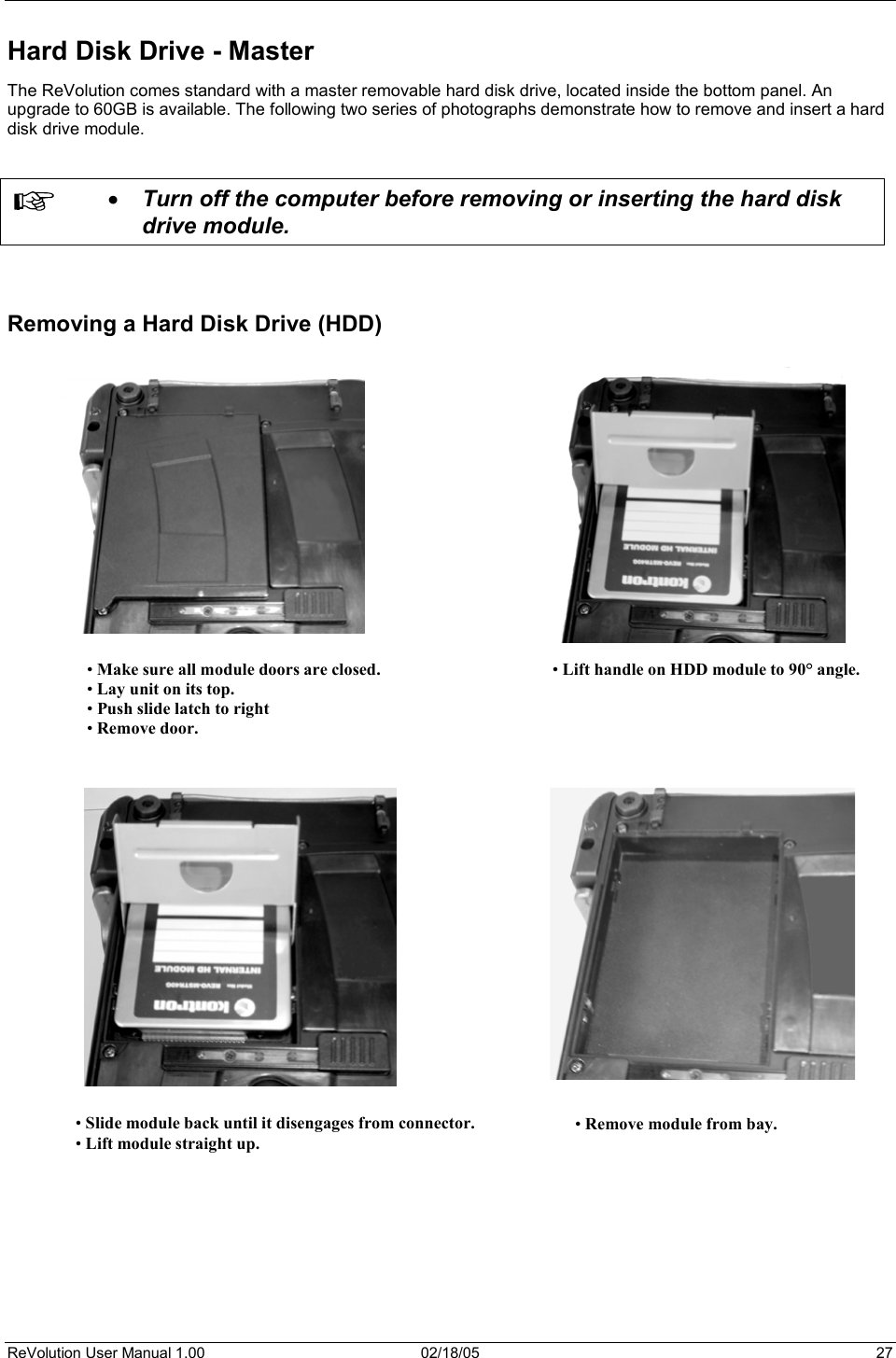
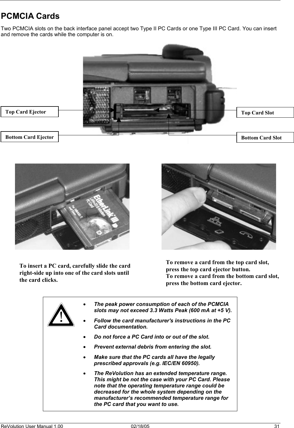
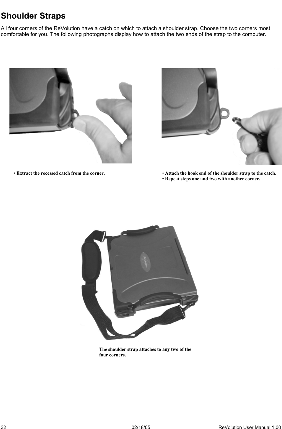
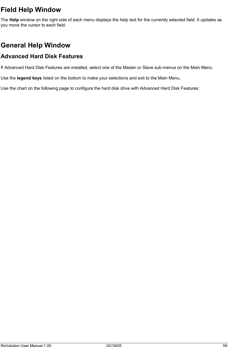
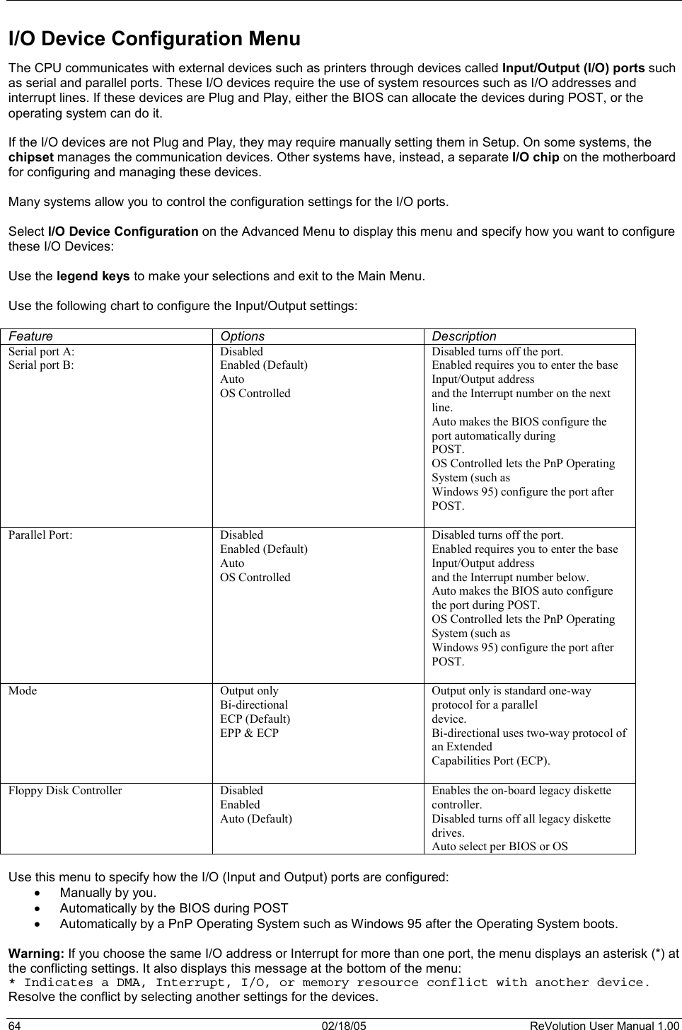
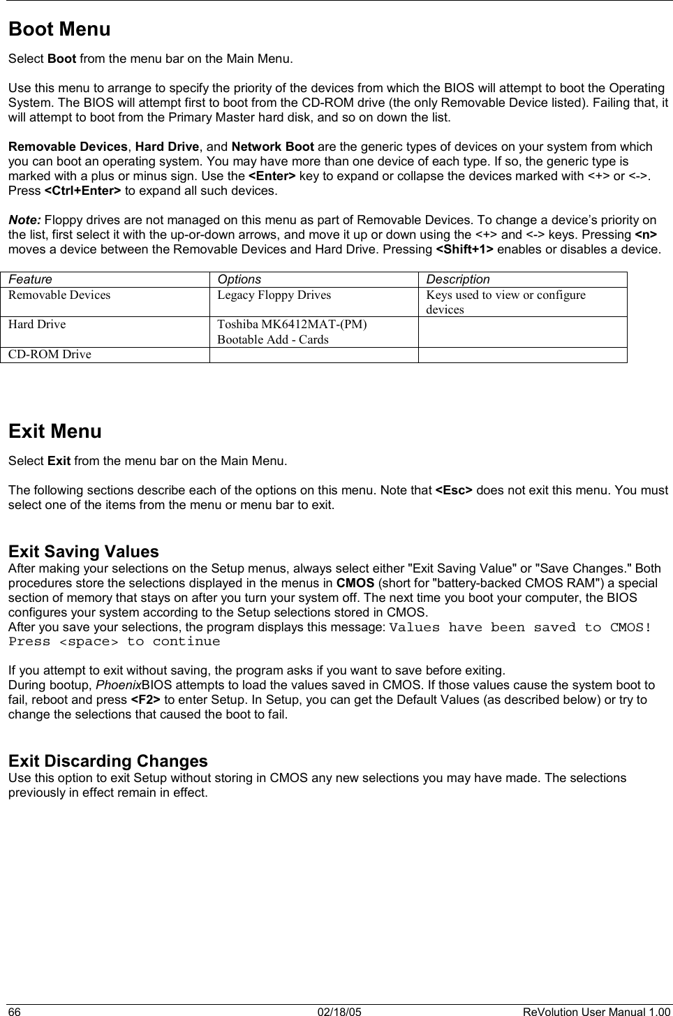
![ReVolution User Manual 1.00 02/18/05 65 Keyboard Features Select Keyboard from the menu bar on the Main Menu. Use the legend keys to make your selections and exit to the Main Menu. Use the following chart to configure the keyboard features: Feature Options Description Numlock Auto OnOff (Default) On or Off turns NumLock on or off at bootup. Auto turns NumLock on if it finds a numeric key pad. Key Click Enabled Disabled (Default) Enables key click.Keyboard auto-repeat rate 2/sec 6/sec 10/sec 13.3/sec 21.8/sec 26.7/sec 30/sec (Default) Sets the number of times per second to repeat a keystroke when you hold the key down.Keyboard auto-lag delay ¼ sec ½ sec (Default) ¾ sec 1 sec Sets the delay time after the key is held down before it begins to repeat the keystroke. Security Menu Select Security from the menu bar on the Main Menu. Use the legend keys to make your selections and exit to the Main Menu. Enabling "Supervisor Password" requires a password for entering Setup. The passwords are not case sensitive. Pressing <Enter> at either Set Supervisor Password or Set User Password displays a dialog box like this: Set Password Enter password: [ ] Confirm password: [ ] Enter: Accept Type the password and press <Enter>. Repeat. Note: In some systems, the User and Supervisor passwords are related; you cannot have a User password without first creating a Supervisor password. In other systems, you can create and use them independently. Use the following chart to configure the system-security and anti-virus options. Feature Options Description Set Supervisor Password Up to seven alphanumeric charactersPressing <Enter> displays dialog box for entering the supervisor password. In related systems, this password gives full access to Setup menus. Set User Password Up to seven alphanumeric charactersPressing <Enter> displays the dialog box for entering the user password. In related systems, this password gives restricted access to SETUP menus.Password on Boot Enabled DisabledEnabled requires a password on boot. Requires prior setting of the Supervisor password. If supervisor password is set and this option disabled, BIOS assumes user is booting. Diskette Access Enabled DisabledEnabled requires a password to boot from or access the floppy disk.](https://usermanual.wiki/Kontron-Embedded-Technology/REVOLUTION-V5/User-Guide-520595-Page-73.png)