Korea Data Systems Co CT1504 15” LCD Monitor User Manual 1 intro1 1904
Korea Data Systems Co Ltd 15” LCD Monitor 1 intro1 1904
UserManual.wiki
>
Korea Data Systems Co
>
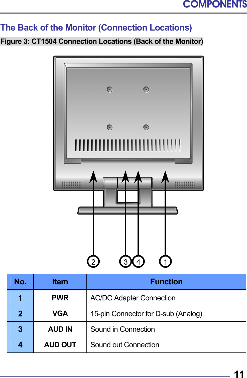
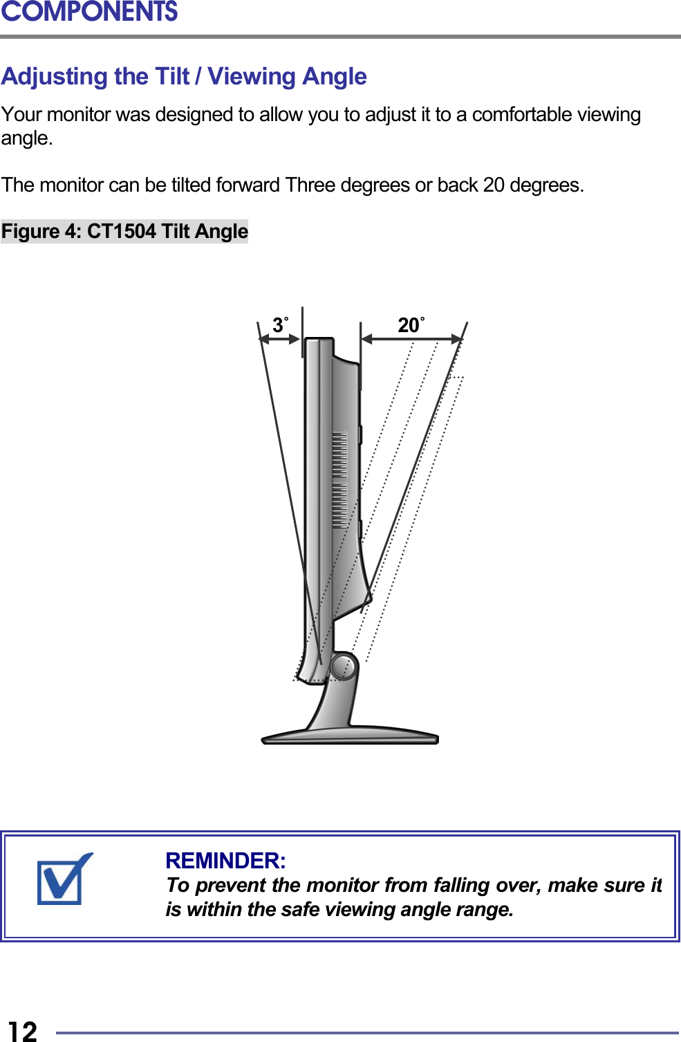
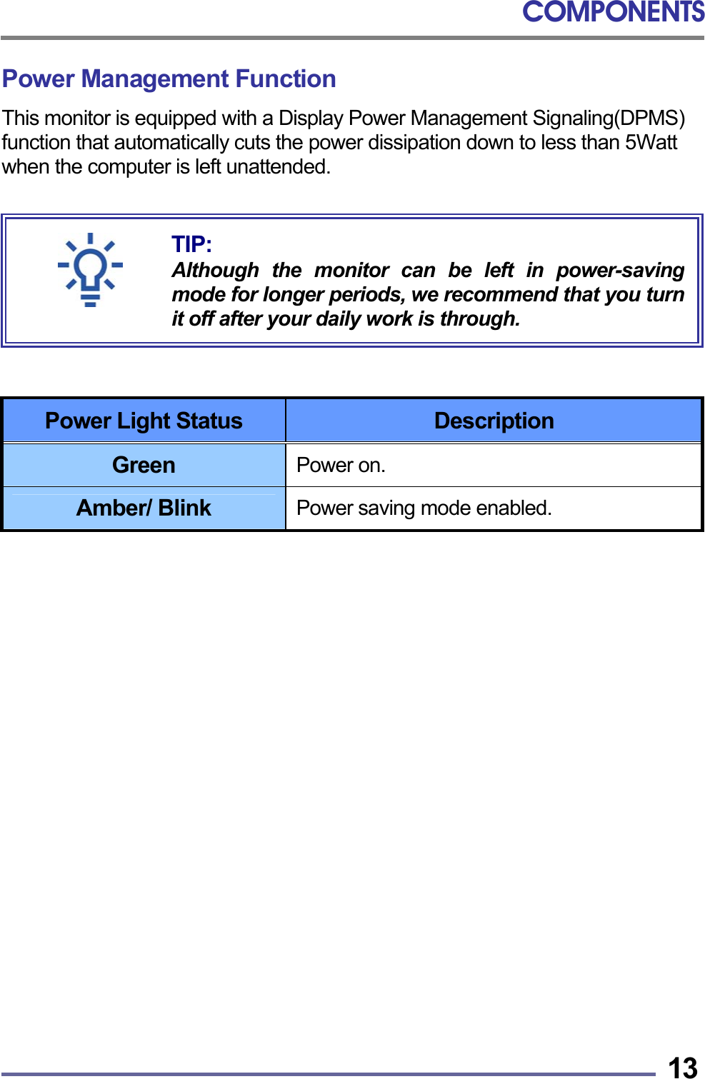
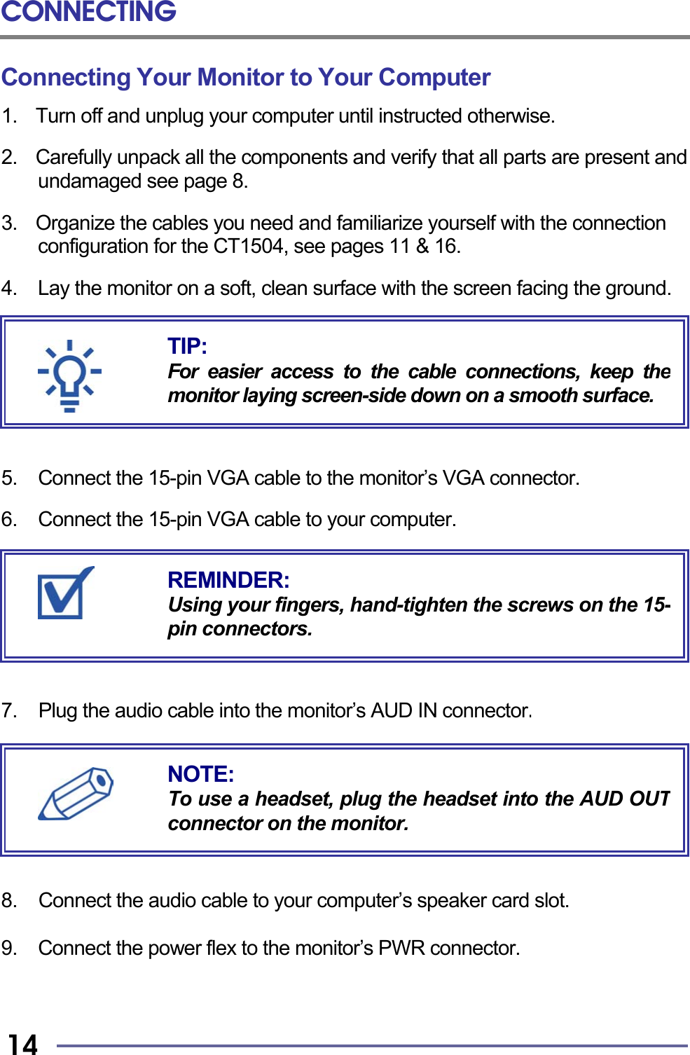
CT1504 User Manual
User Manual
Navigation menu
Upload a User Manual
Namespaces
Wiki Guide
HTML
PDF
Info
Views
User Manual
Discussion / Help
Navigation