Korea Data Systems Co KDT-3863 Personal Computer User Manual G P 1 p65
Korea Data Systems Co Ltd Personal Computer G P 1 p65
UserManual.wiki
>
Korea Data Systems Co
>
KDT 3863 User Manual
User Manual
Navigation menu
Upload a User Manual
Namespaces
Wiki Guide
HTML
PDF
Info
Views
User Manual
Discussion / Help
Navigation
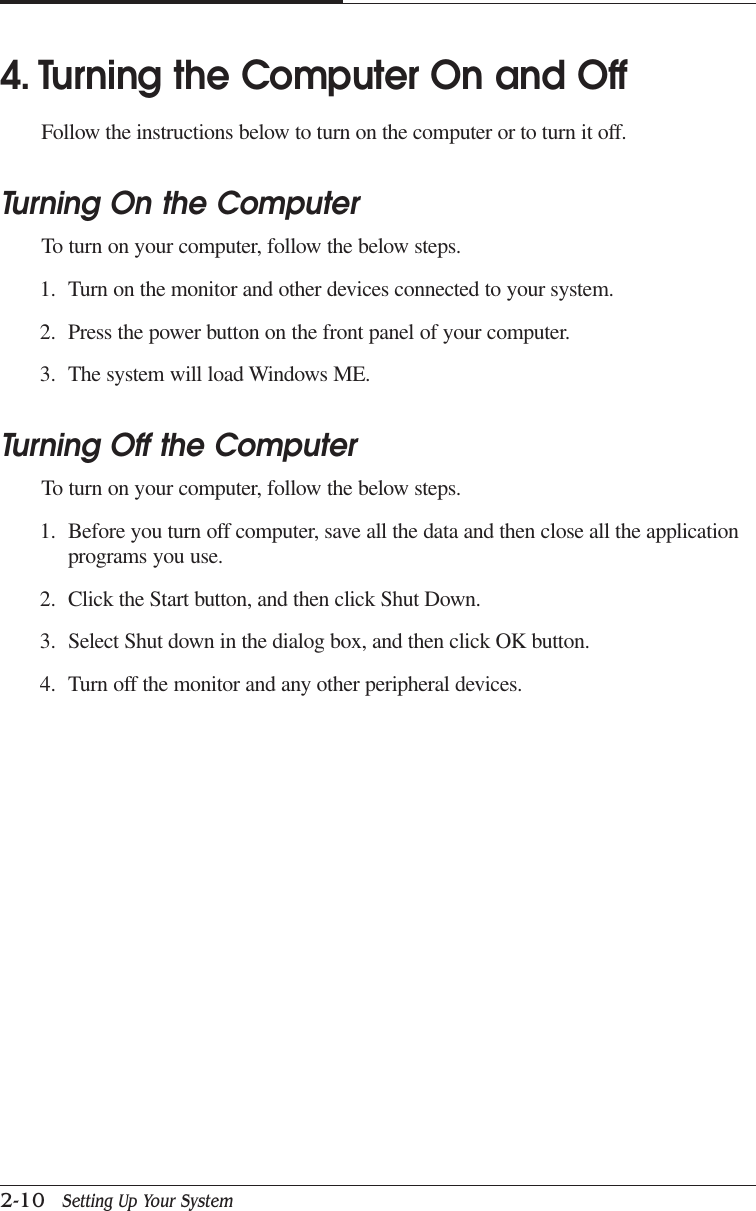

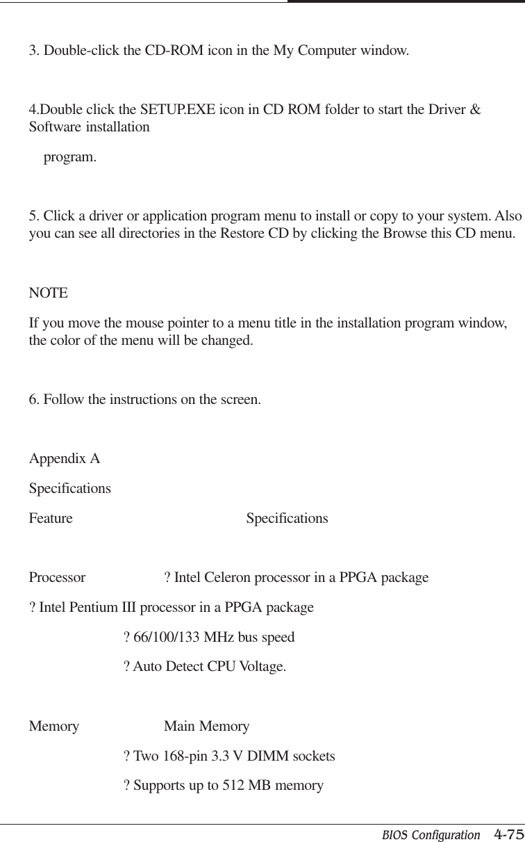
![BIOS Configuration 4-29CAPTUER 4* FDC/COM/LPT PortThe default value is EnabledDisable Disable this functionEnabled Enable monitor FDC/COM/LPT for Green event.* PCI RIRQ [A-D] #The default value is EnabledDisable Monitor PCI PIRQ [A-D] IRQ ActiveEnabled Ignore PCI PIRT [A-D] IRQ Active4.10 PnP/PCI Configurations* PNP OS InstalledThe default value is NoYes Enable PNP OS Installed functionNo Disable PNP OS Installed function](https://usermanual.wiki/Korea-Data-Systems-Co/KDT-3863/User-Guide-155309-Page-59.png)
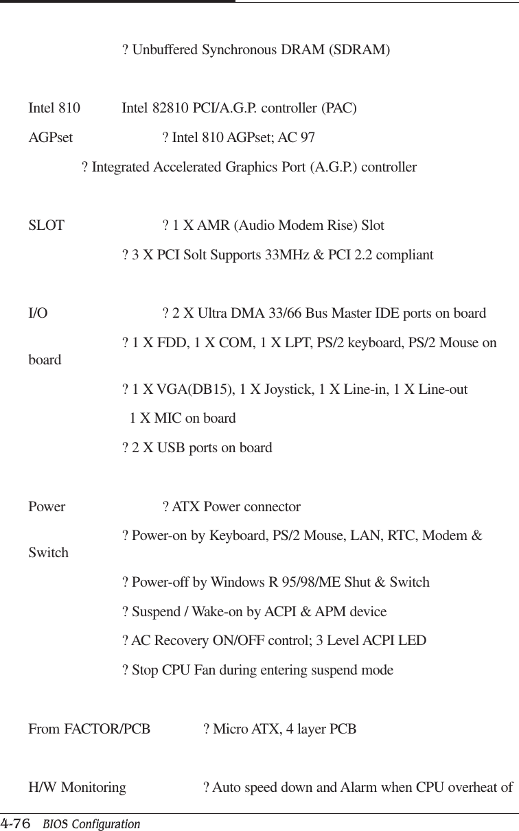
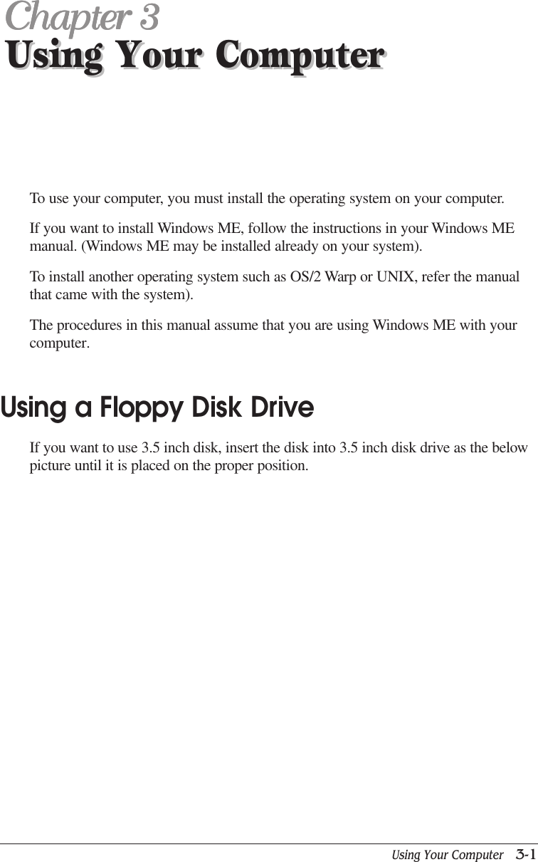
![CAPTUER 44-80 BIOS ConfigurationYour CD/DVD-ROM drive is not recognized.Turn off the computer, wait at least 30 seconds, and then turn on thecomputer.CD/DVD has been inserted upside down.Eject the CD/DVD, turn it over, then reload. (The label on the CD/DVD shouldbe facing up.)CD/DVD is dirty.Clean the CD/DVD with a CD/DVD cleaning kit (available incomputer stores).CD/DVD is defected.Try another CD/DVD. If it operates well, the CD/DVD is defected.How to use the CD/DVD-ROM drive in Real MS-DOS mode?If you reboot your computer by selecting "Restart in MS-DOSmode" option in"Shut Down Windows," you can use the CD/DVD-ROM drive.However, to use the CD/DVD-ROM drive in real MS-DOS mode,manually delete the"REM" of the line "REM Mscdex /d:gem001" in the AUTOEXEC.BAT file.<AUTOEXEC.BAT>...REM [CD-ROM DRIVE]Mscdex /d:gem001](https://usermanual.wiki/Korea-Data-Systems-Co/KDT-3863/User-Guide-155309-Page-110.png)
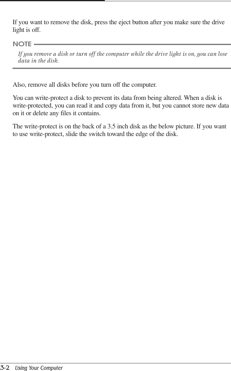
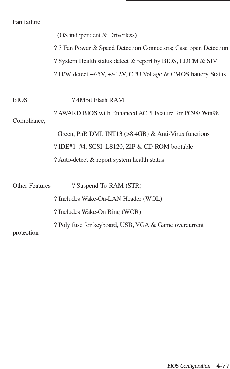
![CAPTUER 44-92 BIOS ConfigurationAttentionDebrancher avant d’ouvrir. Apparaten skall anslutas till jordat natuttag.AtencionDesconecte fuerza electrica antes del servicio. Laite on liitettavasuojakosketinistoraasian.Laser ProductClass 1 Laser ProductThis equipment complies with European Standard EN60825 [harmonized withInternationalElectrotechnical Commission (IEC) Publication 825].This equipment is classified as a Class 1 LASER product and there is no hazardousLASERradiation with the safety protection.CautionThe laser used in the CD-ROM drive can damage your eyes. Do not attempt to openthe cover.To reduce the risk of electric shock, do not remove cover (or back).No user-serviceable parts inside.Refer servicing to qualified service personnel.Use of controls or adjustments or performance of procedures other than thosespecified hereinmay result in hazardous radiation exposure.Do not open the top cover of the drive and never touch the internal parts in order toavoid EXPOSURE TO INVISIBLE LASER RADIATION.When the power switch is On, do not place your eyes close to the font panel opening](https://usermanual.wiki/Korea-Data-Systems-Co/KDT-3863/User-Guide-155309-Page-122.png)