Kowa Nonmyd WX 3D User Manual To The E12389df 8249 4d13 A8c7 Eb0fc105c7c8
User Manual: Kowa nonmyd WX 3D to the manual
Open the PDF directly: View PDF  .
.
Page Count: 64
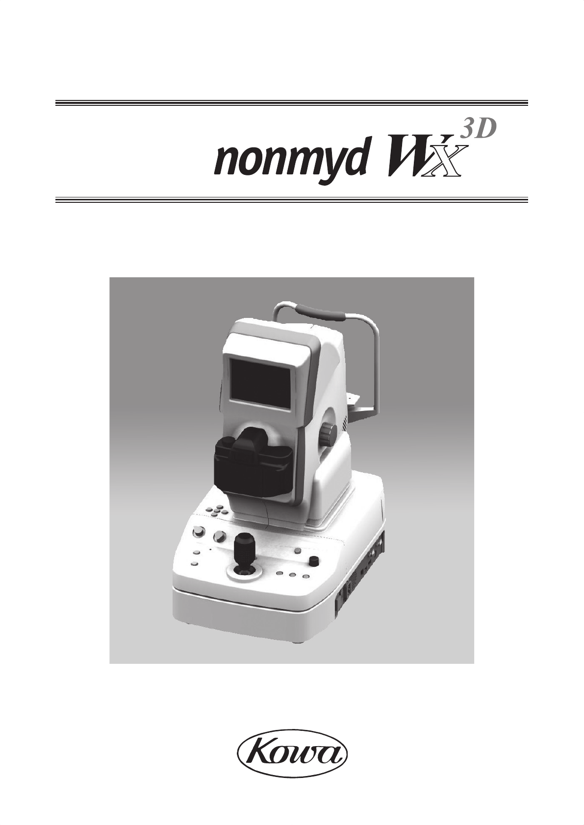
INSTRUCTION MANUAL
2D/3D Non-mydriatic Retinal Camera
Kowa
KOWA nonmyd WX EU

I
Accept our congratulations on your purchase of KOWA nonmyd WX.
KOWA nonmyd WX is a Non-mydriatic retinal camera for mono and stereo retinal photography.
This manual provides a description of the operation procedures of KOWA nonmyd WX and important precautions to be
observed during its use.
Please read this manual carefully to assure that the instrument can demonstrate its full capabilities and work safely.
After you have nished reading, keep this manual in an easily accessible location near the instrument for future refer-
ence.
Operational considerations for safety
This manual describes important precautions to be observed when you use this system to assure that the system is used
safely without causing any damage to the human body or property of the purchaser and other persons.
The designations and pictorial symbols used in this manual have the following meanings.
These should be fully comprehended before reading the text of this manual.
Meanings of designations
Warning If the instrument should be operated wrongly, there may incur a risk of causing
death or serious injury.
Caution If the instrument should be operated wrongly, there may result in a bodily injury*1
or damage to property*2.
k1 A bodily injury means an injury, burn, electrical shock and so forth that will not necessitate hospi-
talization or long-term outpatient treatment.
k2 Damage to property means an extensive damage to a house and/or household goods as well as
a domestic animal and pet.
Meanings of symbols
Graphical indication of any danger (including warning and caution).
What is warned is explicitly and pictorially indicated by a picture or its associ-
ated message on or near a pictorial symbol.
Graphical indication of prohibited operation (prohibitive item).
What is prohibited is explicitly and pictorially indicated by a picture or its as-
sociated message on or near a pictorial symbol.
Graphical indication of any mandatory action (obligatory item).
What must always be done is explicitly and pictorially indicated by a picture
or its associated message on or near a pictorial symbol.
Disclaimer
Kowa is not responsible for:
• Any damage caused by re, earthquake, third party’s action, any other accident or user’s intentional or unintentional
error, abuse or use under abnormal conditions.
• Any damage resulting from use of the product or its malfunction (e.g. operating loss, shutdown, change/loss of stored
data and so forth).
• Any damage resulting from disobedience of what is described in this manual.
• Any damage resulting from, for instance, malfunctioning of instrument caused by a combination of connected devices.
Introduction
II
Warning
Unplug
If any abnormal smell, sound, overheating or smoke should be detected, be sure to turn OFF
the main power immediately and then unplug the instrument from the power outlet.
Continued use of the instrument may cause the instrument to malfunction or cause a re. Con-
tact Kowa or your Kowa dealer for inspection immediately.
Warning
High-Voltage
When replacing the ash lamp, make sure the instrument is turned OFF and then
unplugged from the power outlet. Otherwise, there may occur electrical shock.
When replacing the fuse, make sure the instrument is turned OFF and un-
plugged from the power outlet.
If the fuse holder cover is removed with the instrument unplugged, there may
occur electrical shock.
This instrument is equipped with a storage capacitor for photography light.
Replacing the flash lamp while this capacitor is still not yet fully discharged
causes a danger of an electrical shock. Check that the discharge indicator LED
is turned OFF before replacing the ash lamp.
Obligatory
Be sure to plug into the power outlet completely and securely.
Otherwise there may cause a re or electrical shock.
Use a designated fuse only.
Otherwise, the instrument may malfunction or a re may break out.
Make sure that the instrument is properly grounded to protect from bodily injury. Connect the
plug into the three-wire grounding type outlet with ground wire.
Otherwise, there may occur electrical shock.
Prohibitory
Do not place a container or cup containing liquid near the instrument.
Spilled liquid entering into the instrument may cause electrical shock. If liquid should be spilled
into the instrument, turn OFF the main power and then unplugged from the power outlet. Con-
tact Kowa or your Kowa dealer for inspection.
Do not load the power outlet or cable with excess of its rated capacity.
If the main power cable should share a power outlet with other devices and the rated capacity
is exceeded, there may cause a re or electrical shock.
Do not insert any metal object into an air vent or opening of the instrument. It may cause an
instrument malfunctioning, re or electrical shock.
Disassembly prohibited
Do not disassemble, modify or repair the instrument yourself.
It may cause a re, electrical shock, instrument malfunctioning or bodily injury.
Refer all servicing to Kowa or your Kowa dealer.
The product assembled by yourself will not be covered under warranty nor any other service.
Caution
Obligatory
The power supply must be provided for the sole use of this instrument.
Sharing a same power supply with other devices may cause malfunctioning.
When operating the instrument, take good care so that the patient’s eye, nose or face does not
come in contact with the instrument.
When moving up or down the chin rest to adjust the height of the patient’s eyes, carefully ma-
nipulate the instrument while checking the position of the patients’ head.
A patient with the smaller head may get his or her head caught between the components.
Handle the ash lamps and fuses made of glass with good care.
A A
A
A
A
A
B
C
A
A
A
D
D
III
Caution
Prohibitory
Do not pull the power supply cable when unplugging.
Doing so may damage the cable and cause a re or electrical shock. Be sure to hold the plug
when unplugging.
Do not plug or unplug the power supply cable with wet hand.
Otherwise, there may occur electrical shock.
Do not install the instrument at unstable location such as on a shaky base or a tilting surface.
Doing so may cause the instrument to drop or fall over and result in a bodily injury.
Caution
High-temperature
Do not replace the ash lamp immediately after turning the OFF the main power.
You could be burned by the lamp heated to a high temperature.
Wait for more than 10 minutes to cool the lamp down before replacing.
Do not touch the ash lamp bulb with your bare hand.
Otherwise, the lamp may reduce the light intensity and longevity.
Do not increase the observation illumination light intensity more than required.
Otherwise the eye may be injured.
Do not increase the photography light intensity more than required.
Otherwise the patient may experience pain and his or her eye may be injured.
The air vent must not be obstructed.
Obstructing the air vent may increase the internal temperature resulting in malfunctioning of
the instrument or a re.
Do not insert any metal object into an air vent or opening of the instrument.
It may cause electrical shock and malfunctioning of the instrument.
When operating this instrument, keep your ngers off the gap between the optical head base
and the power supply or the chin rest support and the forehead rest support, or the gap under-
neath the chin rest.
Otherwise, the ngers may be pinched and injured.
Instruct the patient not to place his or her ngers on the instrument.
Do not wipe the outer surface of the instrument with solvents such as benzene, alcohol, or-
ganic solvent, ether.
Doing so may cause discoloration or degradation.
Caution
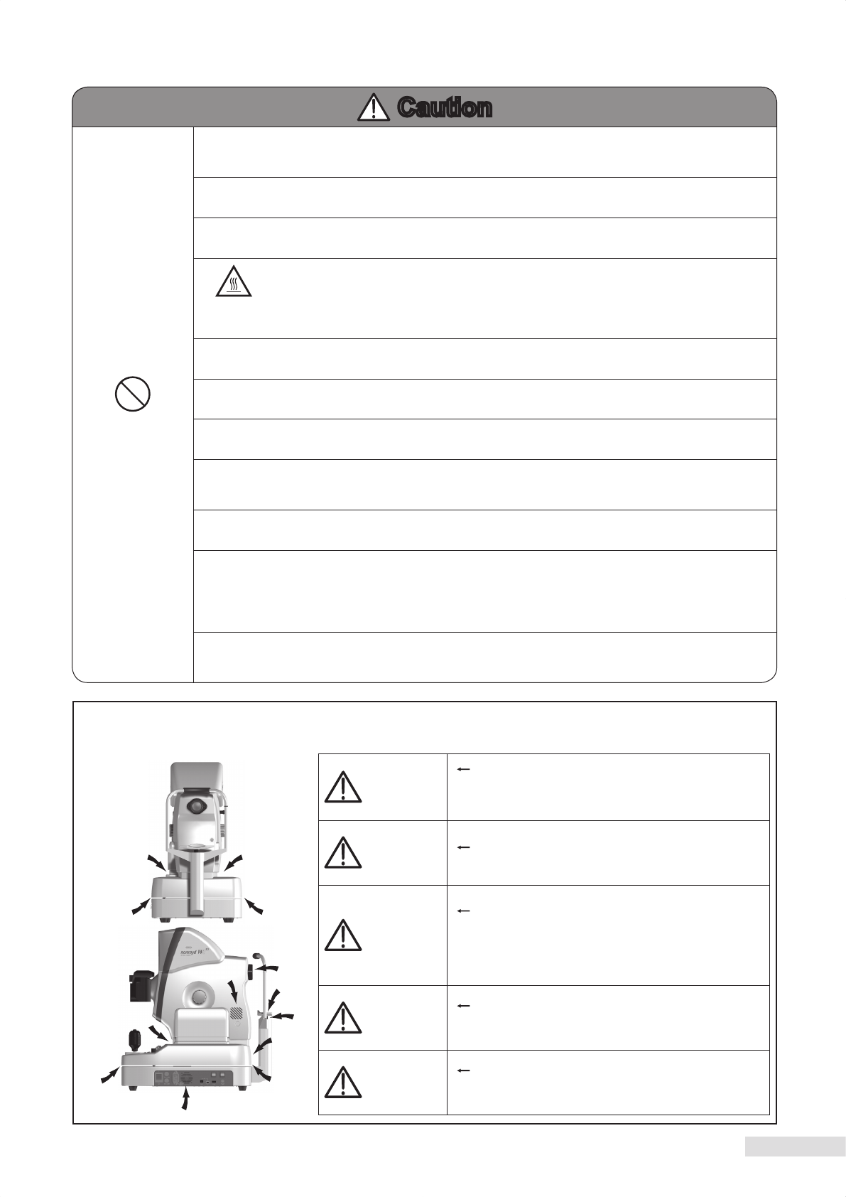
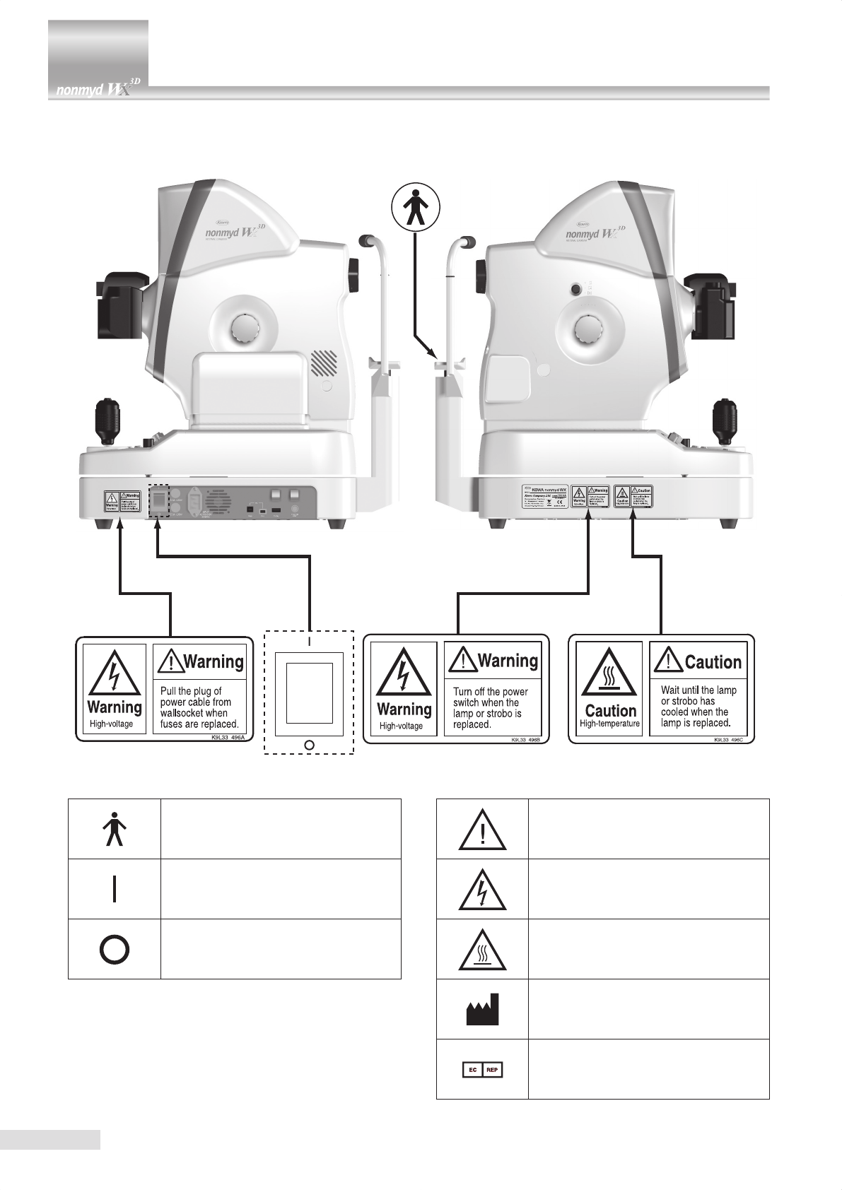
A: Keep your nger off the locations shown with an arrow “A”
when operating the instrument.
Otherwise, the ngers may be pinched and injured.
Instruct the patient not to place his or her ngers on the
instrument.
Caution B: Take good care so that the patient’s eye, nose or face
does not come in contact with the locations shown with
an arrow “B” when operating the instrument.
Caution
C: When moving up or down the chin rest to adjust the
height of the patient’s eyes, carefully manipulate the
instrument while checking the position of the patients’
head.
A patient with the smaller head may get his or her head
caught between the components.
Caution
D: The air vent must not be obstructed.
Obstructing the air vent may increase the internal
temperature resulting in malfunction of the instrument or
a re.
Caution
D: Do not insert any metal object into an air vent or
opening of the instrument.
It may cause electrical shock and malfunctioning of the
instrument.
Keep your nger off the spaces shown with an arrow. Otherwise you may be injured.
IV
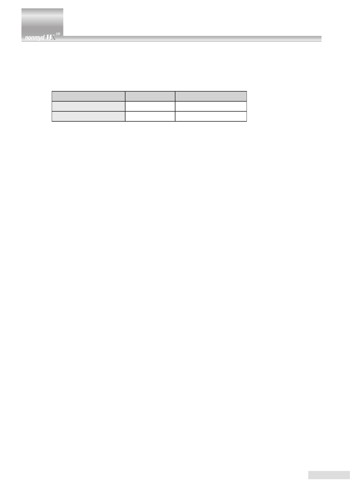
Meanings of symbols
Symbol for “Type B applied part”.
Symbol for “Power ON”.
Symbol for “Power OFF”.
Symbol for “Caution”.
Symbol for “Warning High-voltage”.
Symbol for “Warning High-temperature”.
Symbol for “MANUFACTURER”
Symbol for “AUTHORISED
REPRESENTATIVE IN THE
EUROPEAN COMMUNITY”
V
1. Operating environment
1) Instrument should be operated only by qualied and trained personnel.
2) Handle the instrument with care, and do not apply strong shock to the instrument.
3) Avoid high temperature and humidity, direct sunlight, and dust when installing and storing the instrument. Strictly
observe the following environmental conditions.
Operating Transporting and storing
Environmental temperature 10 to 35 °C -15 to +55 °C
Relative humidity 30 to 90 % 10 to 95 %
4) Avoid condensation when using, transporting or storing the instrument.
5) Use the designated digital camera only since other camera may adversely affect the safety or performance of this
instrument.
6) Install the instrument in a room where the lighting is 5 lux or less which you may barely manage to read a
newspaper.
2. Precautions on electric system
1) When the instrument has not been used for a long period of time, inspect the items below.
Inspect if the objective lens is free from soils.
Inspect if intensity of the lamps appropriately adjustable.
2) Install the system in a location where there is little risk of the plug being pulled out while operating. If the plug should
be pulled out accidentally, be sure to turn OFF the main power before plugging the system back in.
3) Kowa is not liable for malfunctions and/or damages resulting from maintenance and/or repairs performed by the
third party other than an agent authorized by Kowa.
4) Kowa is not liable for malfunctions and/or damages resulting from maintenance and/or repairs using parts other than
repair parts specied by Kowa.
5) The input voltage should always be maintained within ± 10% of the rated voltage.
6) Do not turn ON the ash lamp and adjust photography light intensity at the same time.
7) Wait for approx. 10 seconds to stabilize the power unit after turning the power ON before using the switches on the
operation panel.
8) Do not turn the main power ON and OFF in succession. Allow an interval of at least 10 seconds before turning the
main power ON and OFF.
9) Be sure to turn OFF the main power before connecting an external device.
10) Do not touch the patient and connectors at the same time as it may adversely affect the safety.
11) Disinfect using alcohol the parts accessible by the patient.
12) The power supply must be provided for the sole use of this instrument.
3. Precautions when using a digital camera with this instrument
1) Carefully handle the objective lens as soiled or scratched part of the objective lens may be imaged as white spots.
2) Always cover this instrument and the digital camera when not in use in order to protect them.
3) Do not apply strong shock or force to the objective lens.
4) Set a dial or knob with clicking positions to its designated position. The dislocated diopter compensation knob may
result in a photograph with a missing part or underexposure.
5) Securely install the digital camera. The digital camera installed insecurely may cause distortion of an image or
misalignment of focus.
The digital camera installed insecurely may fall off and become unusable.
6) Never disassemble or adjust this instrument or the digital camera by yourself as it uses precision parts which
requires special tool for doing so.
4. Disposal precautions
1) LCD monitor of this instrument has a uorescent lamp that contains mercury. When disposing this instrument,
applicable federal, state, and local regulations must be observed.
2) When disposing, this instrument and/or its consumables is categorized as industrial waste; therefore, the disposal
must be handled by licensed industrial waste disposal contractor.
Operating precautions

VI
1. Precautions on use of medical electrical system
1) All components of this medical electrical system may be installed within a limited patient environment (a radius of 1.5
m around a patient) when all components are installed in accordance with the installation instructions using “Multi-tap
with Isolation Transformer”, which is one of the system components.
2) As prerequisite for installing to this system, other components (a PC, printer, video capture printer, video monitor,
or other devices) which do not comply with IEC60601-1 must be powered from Multi-tap with Isolation Transformer.
The electric power to these components supplied from an electric source other than Multi-tap with Isolation
Transformer (e.g., wall outlets) may cause increased enclosure leakage current or potential difference between
protective grounds resulting in the injury to the patient or operator. Use Multi-tap with Isolation Transformer only for
supplying the power to the components other than the system components.
3) Any medical electrical equipment that connected to this system to compose a medical system must comply with
IEC60601-1.
4) Any non-medical electrical equipment that is connected to this system to compose a medical system must comply
with safety standards of IEC or ISO provisions applicable to such a non-medical electrical equipment.
5) Do not use any additional multi-tap or extension power cable other than those Kowa specied to this system.
6) Power supply to this system or “Multi-tap with Isolation Transformer” must be provided individually. (Do not route
the power supply through other multi-tap to the system or “Multi-tap with Isolation Transformer”.)
7) The power cable for an electrical equipment that compose a medical system must have durability that meets
IEC60245/IEC60227 or higher standards.
8) Assure that the power supply is turned OFF when connecting other device to the system.
9) Do not turn ON the power supply until all devices are completely connected.
10) Do not place or install the devices and the system components on the unstable or inclined table.
2. Precautions for use of “Multi-tap with Isolation Transformer”
1) Do not place “Multi-tap with Isolation Transformer” directly on the oor. Water droplets during room cleaning may
enter the multi-tap resulting in the component failure.
2) The power supply cable to “Multi-tap with Isolation Transformer” must be connected to a power receptacle with a
protective ground terminal equipotential to the protective ground of this instrument.
3) When using a multi-tap power receptacle with a protective ground terminal, read the instruction for use attached to
the receptacle to familiarize yourself with the correct use before use.
3. Daily maintenance and cleaning
1) System components
• Wipe the soiled outer surface with rmly squeezed dampened soft cloth. Use mild detergent to remove excessive
soils. Do not use chemicals or solvents such as thinner and benzene. (As the LCD monitor screen cover easily gets
scratched, lightly wipe it with soft cloth such as gauze.)
• Refer to the instruction for use provided with each device for details of device maintenance and cleaning.
2) Power cables, connecting cables, and connectors
• Visually inspect that all cables have no aw or damage.
• Visually verify that earth leads of all components and protective ground terminals are securely connected.
• Disconnect the power cables from the power supply receptacles when you do not use the system for a long period
of time.
3) Others
• When you add a PC to the system for a ling purpose, captured images are stored in the HDD of the PC. Back up
the data stored in the HDD regularly since HDDs may have a mechanical or electrical failure.
Precautions: use of medical electrical system
VII
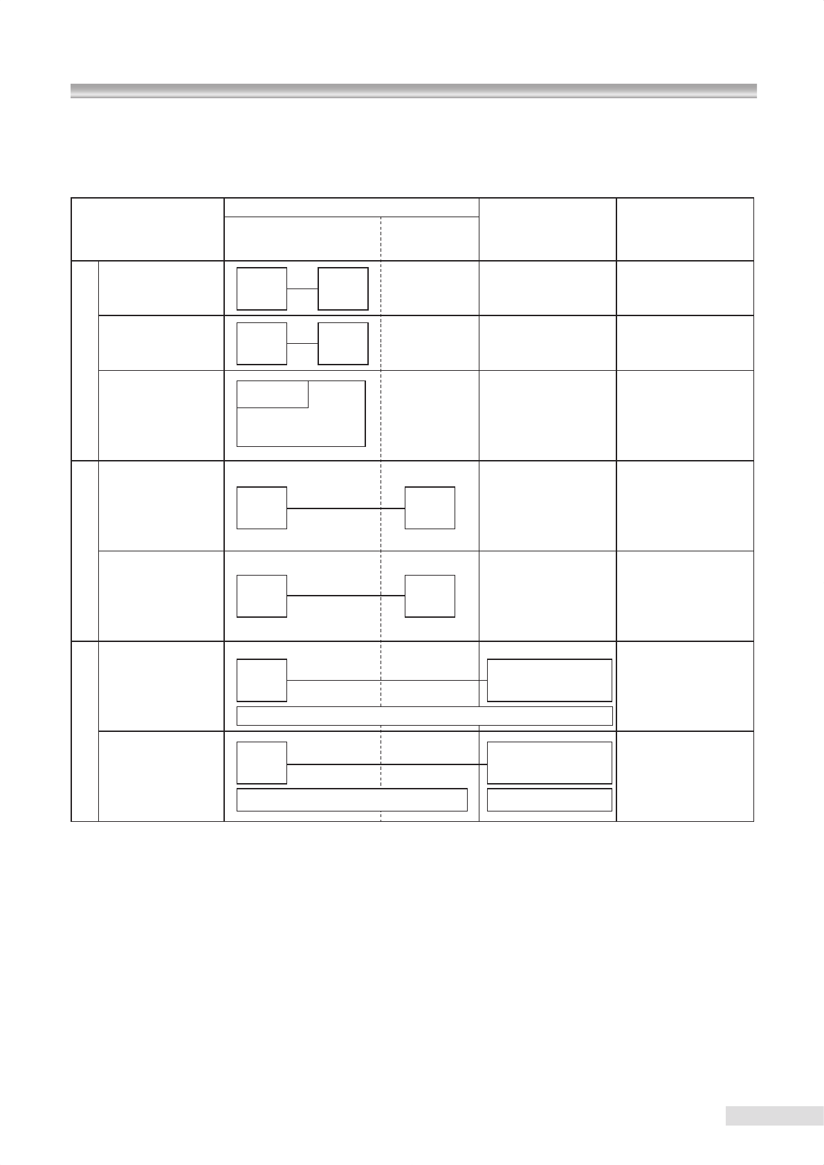
● Combination of medical electrical equipment and non-medical electrical equipment
IEC 60601-1-1 “Safety requirements for medical electrical systems” describes the components combination grouped into
various clinical settings. The brief overview of IEC 60601-1-1 is shown below.
Situation No.
Medically used room
Non-medically
used room
Feasible solution
(See clause 19 in all
situations)
Inside
the PATIENT
ENVIRONMENT
Outside
the PATIENT
ENVIRONMENT
1
1a Items A and B in
PATIENT ENVIRON-
MENT
A
IEC
60601
B
IEC
60601
1b Items A and B in
PATIENT ENVIRON-
MENT
A
IEC
60601
B
IEC
XXXXX
For B:Additional
protective earth or
separating transformer
1c Item A powerd from
specified power supply
in item B in PATIENT
ENVIRONMENT
B
IEC XXXXX
For B:Additional
protective earth or
separating transformer
2
2a Item A in PATIENT
ENVIRONMENT and
item B in medi c a l l y
used room
A
IEC
60601
B
IEC
60601
2b Item A in PATIENT
ENVIRONMENT and
item B in medi c a l l y
used room
A
IEC
60601
B
IEC
XXXXX
For B:See 19.201
and its rationale
3
3a Item A in PATIENT
ENVIRONMENT and
item B in non-medically
used room
A
IEC
60601
B
IEC 60601
or IEC XXXXX
For B:See 19.201
and its rationale
3b Item A in PATIENT
ENVIRONMENT and
item B in non-medically
used room
A
IEC
60601
B
IEC 60601
or IEC XXXXX
For B:Additional
protective earth or
SEPARATION DEVICE
KEY TO TABLE
• Additional protective earth : If necessary, provide additional protective earthing , which is permanently connected(See also
58.201).
NOTE Equipment modication may be required.
• Separating transformer : If necessary, limit the ENCLOSURE LEAKAGE CURRENT, by using an additional separating
transformer according to annex EEE.
NOTE1 No equipment modication is required.
NOTE2 A separating transformer is a transformer with one or more input winding(s) separated from the output winding(s) by at
least basic insulation [IEC 60989]
• SEPARATION DEVICE : If necessary, apply SEPARATION DEVICE.
• IEC 60601 : MEDICAL ELECTRICAL EQUIPMENT in compliance with IEC 60601.
• IEC XXXXX : Non medical equipment in compliance with relevant IEC safety standards.
Common protective earth
Protective earth
Protective earth with po-
tential difference
A
IEC 60601

VIII
1. Only qualied personnel should operate this instrument.
2. The following items shall be considered when installing the instrument.
1) Install at a location away from water or accidental splashing.
2) Install at a location which will not be adversely affected by atmospheric pressure, temperature, humidity, ventilation,
sunlight, dust, air containing salt, sulfur and other substances, and the like.
3) Take care to guard against tilt, vibration and strong impacts, for instance, during transportation.
4) Instrument must not be installed at locations where chemicals are stored or gasses are generated.
5)
Be careful with the radio frequencies, voltages and allowable amperes (power consumption) of the power supply.
6) Properly connect ground wires.
3. The following items shall be considered before using the instrument.
1) Make sure that instrument activates properly after checking switch contact, polarity, dial setting and meters and so
forth.
2) Make sure that the instrument is properly grounded.
3) Make sure that all cords are properly connected and secured.
4) Use of other instruments and appliances on the same power circuit is liable to cause errors and incorrect ash
output resulting in incorrect diagnosis or hazards.
5) External circuits and connectors that may come in direct contact with the patient must be checked frequently for
signs of wear.
4. The following items shall be considered when using the instrument.
1) Be sure to minimize the time and quantity required for diagnosis and treatment.
2) Always assure that the instrument and patient are in good condition.
3) When an abnormality is found on the instrument, take proper measures, for instance, to stop the operation of the
instrument while assuring the patient’s safety.
4) Do not allow the patient to touch any of the instrument controls.
5. The following items shall be considered after using the instrument.
1) Turn OFF the instrument after setting control switches, dials and so forth to their initial status following with a
specied procedure.
2) Do not pull cords for removal because an excessive force is exerted on them.
3) The following shall be considered regarding storage location.
• Store the instrument at locations free from splashes of water.
• Store at a location which will not be adversely affected by atmospheric pressure, temperature, humidity,
ventilation, sunlight, dust, air containing salt, sulfur and other substances, and the like.
• Take care to guard against tilt, vibration and strong impacts, for instance, during transportation.
• Instrument must not be stored at locations where chemicals are stored or gasses are generated.
4) Clean and rearrange accessories, cords, and the like.
5) The instrument must be cleaned prior to use so that there will be no problem when using it again.
6. In case of a problem or malfunction, stop the operation and contact Kowa or your Kowa dealer for repair.
7. Instrument shall not be modied.
8. Maintenance
1) Periodically check the instrument and its components for any abnormality.
2) When using the instrument that has not been used for a while, it must be checked beforehand to assure that it is in
normal condition and operates safely.
9. Be careful of the possibility that incorrect operation may be caused by strong electromagnetic waves.
This instrument is examined based on EN 60601-1-2:2001.
The purpose of this standard is to keep safety against the dangerous obstacle in typical medical facilities.
When this instrument is inuenced by other instrument, or when it affects other instrument or when there is such fear,
please devise to move this instrument and other apparatus or to make the distance between those instrument.
Moreover, if there is an unknown point, please consult our company, or an agency beforehand.
Operational considerations for hospital grade electrical
instrument (safety and accident prevention)
IX
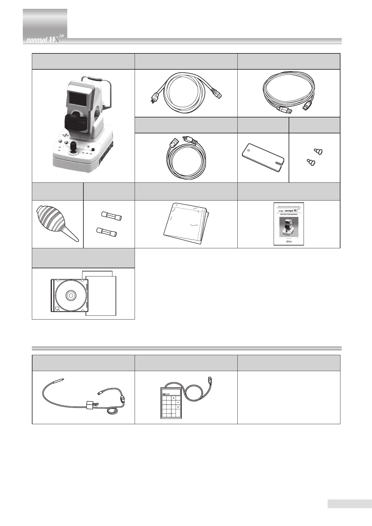
Accessories
Main body:1
digital camera:1 Power supply cable:1(2.5m) USB cable(Type A-B):1(3m)
USB cable(Type A-Mini-B):1(3m) Chin rest paper:1 Chin rest paper
retaining pin:2
Blower:1 Fuses:2 Dust cover:1 Instruction manual:1
Filing software:1
User’s guide:1
Installation manual:1
External xation target:1
K9L-LE57 Numerical keypad:1 PC (ling software) :1
0 00
1 2 3
4 5 6
7 8 9
BS
Enter
Num
Lock /
OS : Windows XP/VISTA
CPU : Celeron 1.0GHz
Memory : 512Mbyte
Display : XGA
* Comparable or higher performance required
Optional accessories
1
Contents
Introduction .................................................. I
Meanings of symbols ................................IV
Operating precautions ...............................V
Precautions: use of medical electrical
system ........................................................VI
Operational considerations for hospital grade electrical
instrument (safety and accident prevention)
.......VIII
Accessories ...............................................IX
Optional accessories ...................................IX
Contents ...................................................... 1
1 System description .................................... 2
1.1 Intended use ................................................ 2
1.2 System overview .......................................... 2
1.3 Features ....................................................... 2
1.4 Name and function of each component ....... 3
2 Installation ................................................... 9
2.1 Installing the system..................................... 9
2.2 Installing external device (optional PC) ...... 11
2.3 Connecting PC ........................................... 11
3 Saving captured images .......................... 12
3.1 Saving captured images in PC
(optional device) ......................................... 12
3.2 Saving captured images in a SD card ........ 12
4 Basic operation......................................... 13
4.1 Moving component xing screw ................. 13
4.2
Coarse motion: moving the optical head base
for a long distance
...................................... 13
4.3 Fine motion: moving the optical head base
for a short distance..................................... 13
4.4
Raising and lowering the optical component
13
4.5 Raising and lowering the chin rest ............. 13
5 Preparations for photography ................. 14
5.1 Preparing the instrument ............................ 14
5.2 Preparations for patient’s eye examination 15
5.3 Selecting a photography mode .................. 15
6 Operational procedure in photography .. 16
6.1 Normal, SP, and stereo modes .................. 16
6.2 Precautions for continuous photography.... 22
6.3 Terminating photography............................ 22
7 Advanced photography ........................... 23
7.1 Mosaic mode photography ......................... 23
7.2 External xation target ............................... 27
7.3 Diopter compensation range ...................... 27
8 Troubleshooting ....................................... 28
9 Menu operation ......................................... 31
9.1 Starting menu ............................................. 31
9.2 Objective lens cleaning lamp ..................... 31
9.3 Mosaic internal xation target setting
(Switching internal xation target in
mosaic mode photography )...................... 31
9.4 Other setting menu..................................... 33
10 Maintenance and inspection ................... 36
10.1 Daily maintenance...................................... 36
10.2 Daily inspection (by users) ......................... 36
10.3 Regular Inspection (by manufacturer) ........ 37
10.4 Cleaning the objective lens ........................ 37
10.5 Disinfection................................................. 38
10.6 Outer cleaning ............................................ 38
10.7 Replacing ash lamp .................................. 38
10.8 Fuse replacement ...................................... 40
10.9 Relling and replacing consumables.......... 40
11 Specications ........................................... 41
12 Technical information .............................. 42
12.1 Description of digital camera ...................... 42
12.2 Digital camera settings ............................... 43
12.3 Imaging conditions output .......................... 44
13 Electromagnetic compatibility
(IEC60601-1-2) ........................................... 45
2
1.1 Intended use
KOWA nonmyd WX is intended for use with retinal image capturing without mydriatic.
The retinal image can be stored to an image ling drive through serial interface.
1.2 System overview
This system is an instrument that enables retinal examination and retinal image capturing using infrared rays without re-
quiring the patients to take any mydriatics and uses the normal or stereo light path to capture, record and display images.
Also the designated ling software installed in a PC allows you to save, register or print the captured images.
1.3 Features
1) One-touch switching Normal, SP and stereo modes.
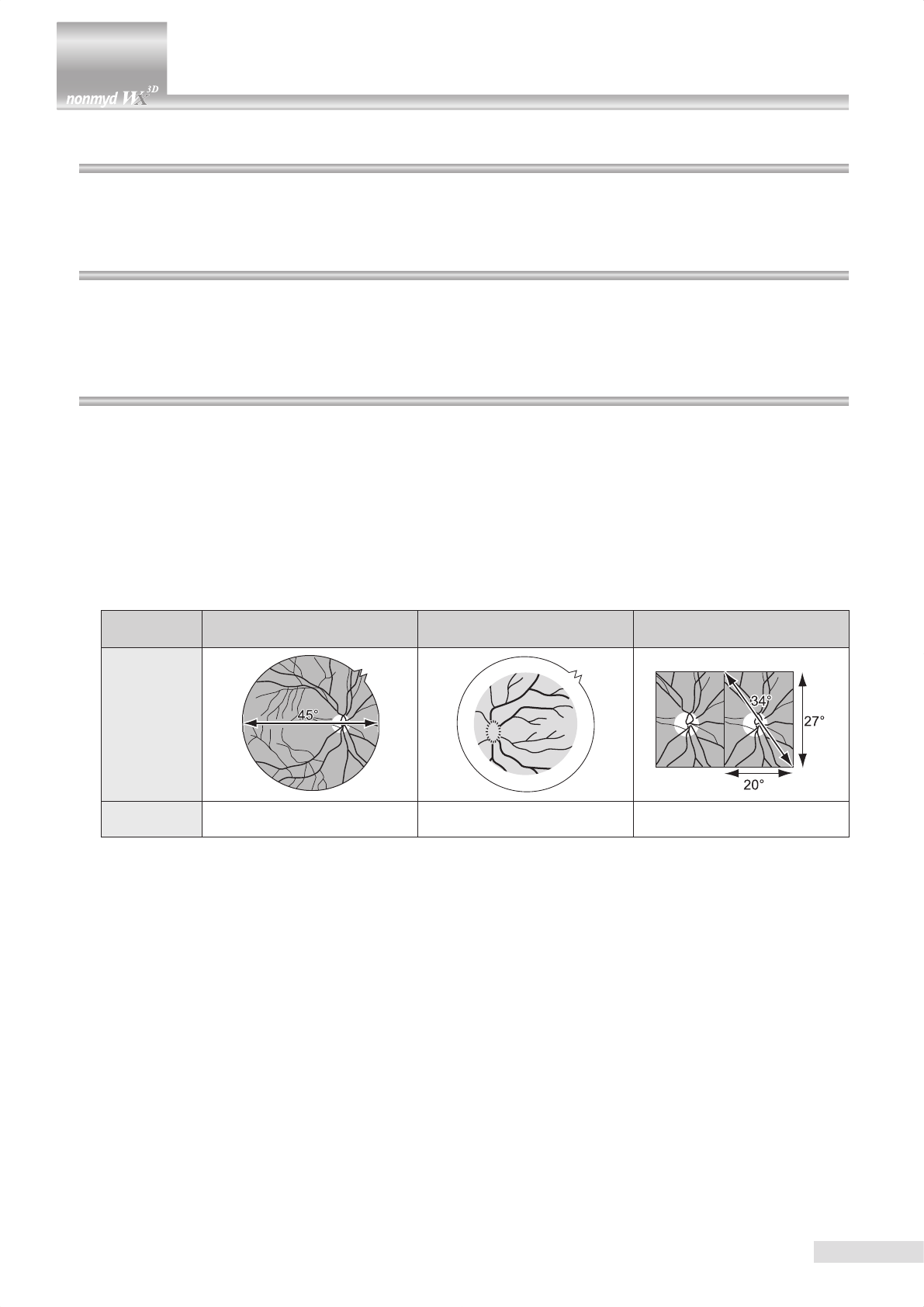
2) Field angles available are 45° with a round mask for normal mode and 34° (20° horizontal and 27° vertical directions)
with a square mask for stereo mode.
3) Functions that support mosaic mode photography.
4) A high resolution digital camera is installed.
5) An intuitive operation panel allows you to diagnose effortlessly.
6) Anterior segment button enables one-touch switching between anterior segment alignment and retinal alignment
screens easily.
Modes and captured images
Photography
mode Normal mode SP (small pupil) mode Stereo mode
Captured
image
Field angle 45° 45° k34°(20°× 27°)
k Some eyes may cause a are around their circumference.
1 System description
3
1.4 Name and function of each component
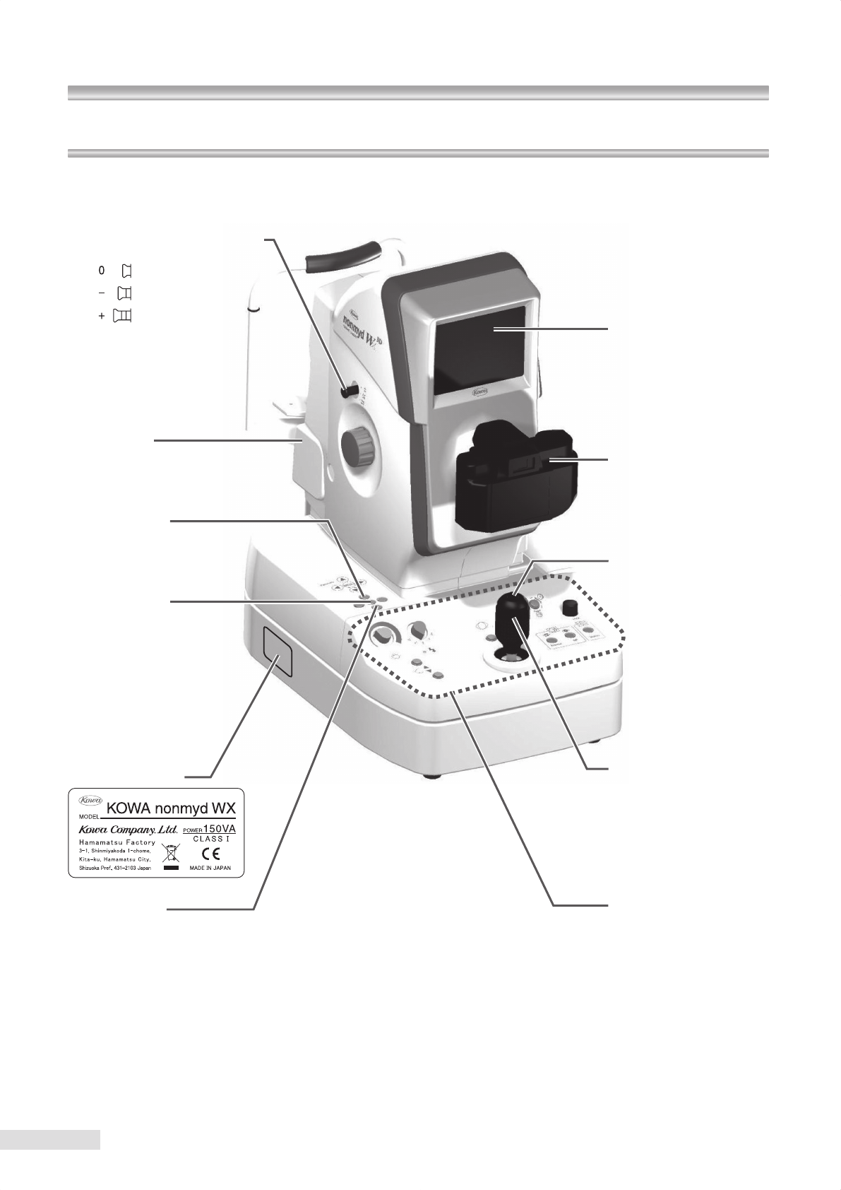
1 System description
If cannot in-focus by turning
the focusing knob, pull the
diopter compensation knob
to make (-) or (+) compensa-
tion until the focus point is
found.
Lamp cover
Remove this cover to replace
a ash lamp.
Mosaic button
Use this button to select ei-
ther mosaic ON or OFF.
Menu buttons
Hold down the center button
more than 2 seconds to access
the menu mode for various set-
tings of the instrument. You can
also switch the internal xation
target position for the auto set-
ting of internal fixation target
position during mosaic mode
photography.
LCD monitor
Black-and-white live image
of the anterior segment and
retinal appears for you to
use for alignment and fo-
cusing.
Digital camera
Stores and displays cap-
tured images.
Shutter button
Pressing this button turns
the flash on and takes a
photo.
Control lever
Use this lev er to m ove
around the optical head
base. Turning the control
lever moves the optical
head base vertically.
Blue / Brown
selection switch
Use this switch for setting
the intensity suitable for blue
or brown eye.
Instrument label
Operation panel
(See the next page for de-
tails)
Diopter compensation knob
4
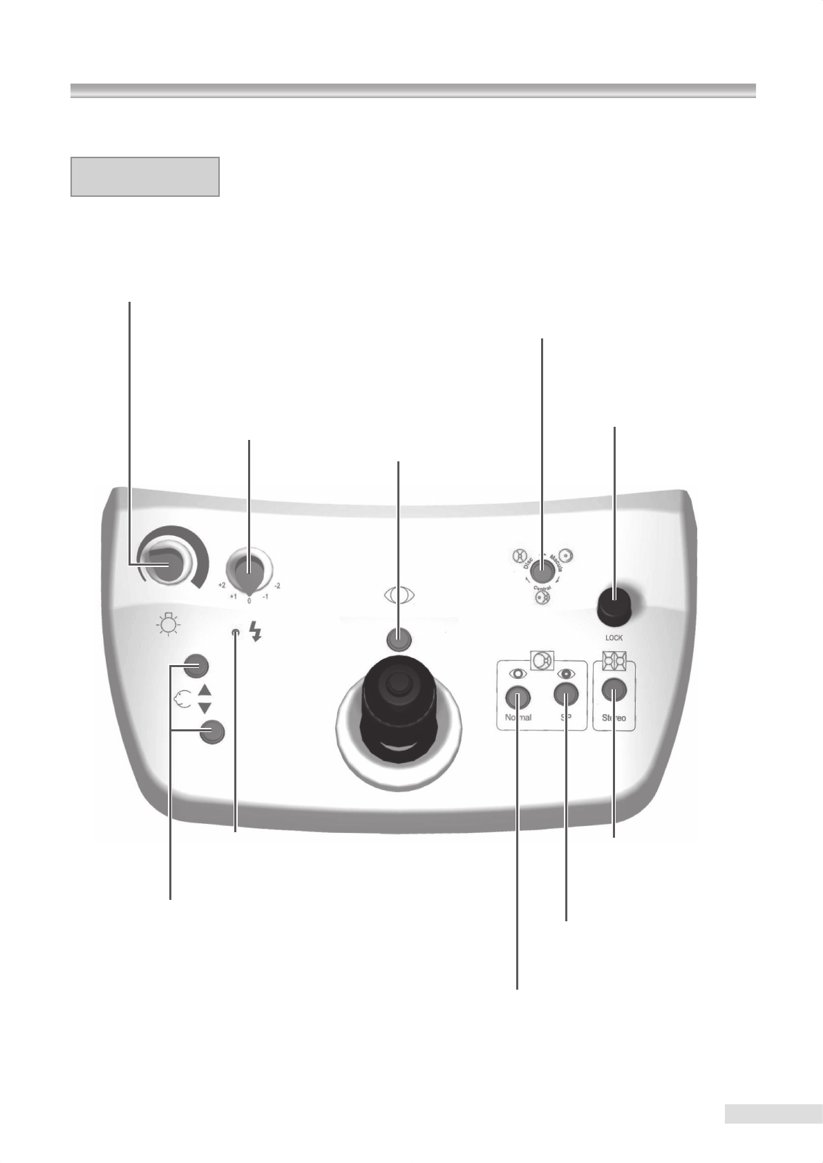
1.4 Name and function of each component
Retinal observation light
intensity control knob
Used for adjusting light intensity
during retinal observation.
Exposure compensation
knob
Used for adjusting the photog-
raphy light intensity when pho-
tographing.
Internal xation target selection button
Switch the internal xation target position to posterior, optic disc, and center of mac-
ula by pressing this button to go through these selections in normal mode. (In stereo
mode, pressing this button goes through optic disc, center of macula and then poste-
rior.) The button turns OFF for posterior, illuminates for optic disc, and ushes for cen-
ters of macula. This button turns OFF during mosaic mode photography and the inter-
nal xation target selection function becomes disabled.
Anterior segment button
Pressing this button switches the
image shown on the LCD monitor
between anterior segment and reti-
nal. The button illuminates when
the anterior segment is selected.
Moving component xing screw
Tighten the screw when you need to
x the moving component.
Stereo mode button
Used for a stereo image with
the eld angle of 34° (20° hor-
izontal and 27° vertical direc-
tions).
SP mode button
Used for an image with the
eld angle of 45° for a small
pupil diameter.
Normal mode button
Used for an image with the
eld angle of 45° for a normal
pupil diameter.
Chin rest raising and lowering buttons
Used for raising or lowering the chin rest. The button illu-
minates normally and ashes when it is in “SLEEP MODE”.
Exposure compensation indicator
Illuminates when exposure compensation knob is
in any position other than “0” and turns OFF in “0”.
Operation panel
5
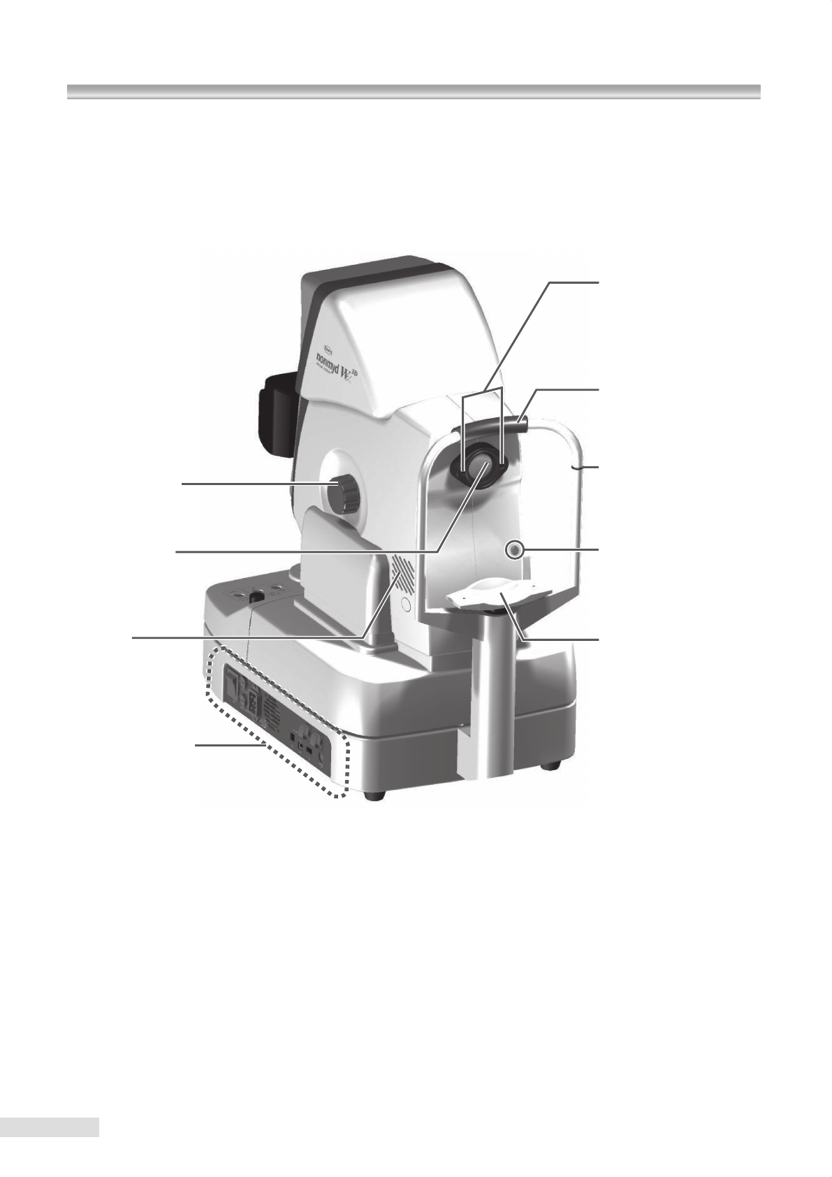
Focusing knobs
Knobs located on both sides of the
optical head base
, used for focusing.
Objective lens
Chin rest
Used for sustaining the pa-
tient’s chin position.
Lamp cover screw
Loosen this screws to re-
move the lamp cover.
Eye level mark
Used for aligning the verti-
cal position of the patient’s
eye with this mark.
Forehead rest
Used for resting the patient’s
forehead against it.
Anterior segment
observation lamp
Infrared LED lamp that illu-
minates when the anterior
segment is observed.
Power supply unit
(See the next page for details)
1 System Description
Air vent
Optical head base
Main unit
Optical component
Power supplyMoving component
6
1.4 Name and function of each component
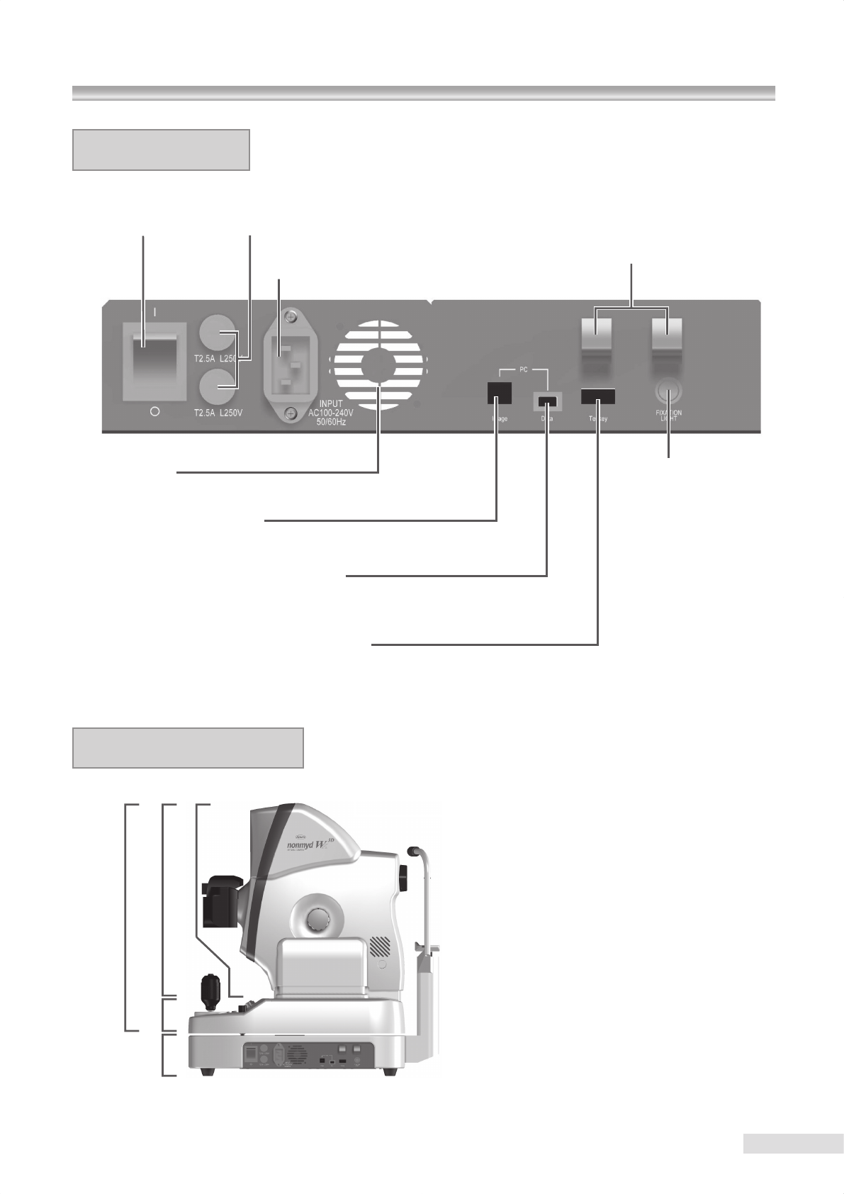
Power switch
| :ON q:OFF Fuse holder
Electrical supply inlet
Air vent
Image output terminal
Used for connecting a PC to the instrument using a USB cable supplied.
Imaging condition output terminal
When you wish to acquire both captured images and imaging condition, use the USB
cable supplied with this instrument to connect a PC to the instrument.
Numerical keypad connecting terminal
Connect a numerical keypad (optional
accessory
) using this terminal when you dene
an internal xation target position of your choice for mosaic mode photography.
Cable clamps
Used for holding cables to keep
them from being disconnected.
External xation target
connecting terminal
A terminal which you connect
an external xation target (op-
tional accessory: K9L-LE57).
Power supply unit
Overall system schematic
7
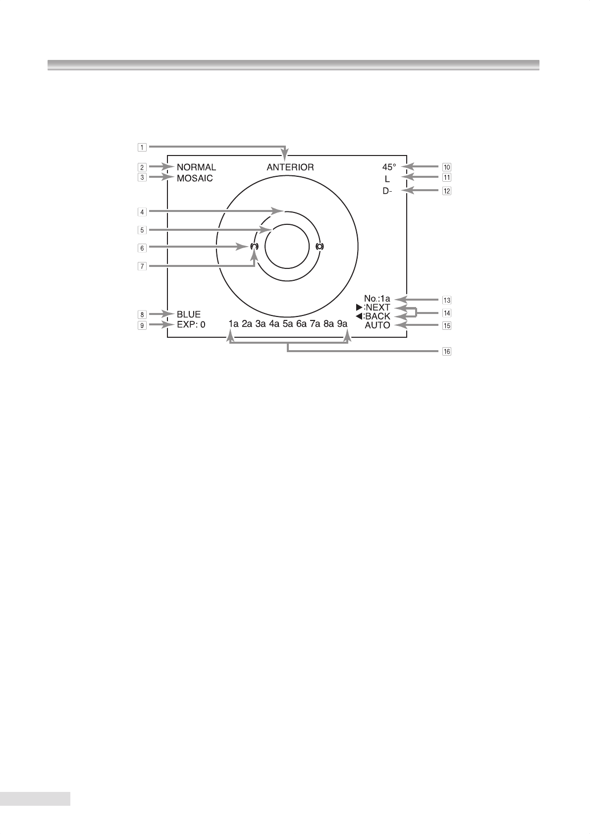
1 Anterior
“ANTERIOR” indicates that the instrument is currently
showing the anterior segment observation display.
anterior segment observation : ANTERIOR
retinal observation : none
2 Photography mode
This indicates the current photography mode.
Normal mode : NORMAL
SP mode : SMALL PUPIL
Stereo mode : STEREO
3 Mosaic mode photography
ON : MOSAIC
OFF : none
4 Pupil diameter aid for normal or stereo mode
This aid appears when normal or stereo mode is selected.
5 Pupil diameter aid for SP mode aids
these aids appear when SP mode is selected.
6 Anterior segment working dot position aids
These aids appear during anterior segment observation
for you to adjust the working dots.
7 Working dots
The dots are shown optically for you to adjust the distance
and position of a patient’s eye.
8 Blue eye
This indicates the current Blue / Brown selection switch
status.
BLUE : Blue
BROWN : none
9 Exposure compensation
This indicates the current exposure compensation knob
position.
+ 2/ + 1/0/ − 1/ − 2
0 Field angle
This indicates the eld angle currently selected.
Normal
or SP mode : 45˚
Stereo mode : 20˚ x 27˚
A Left or right eye
This indicates which eye you are currently observing.
Left eye : L
Right eye : R
B Diopter compensation
This indicates the diopter compensation knob position.
No corrective lens used (−12 m-1(D) to +13 m-1(D)) : none
+
compensation
(+10 m-1(D) to +35 m-1(D)) : D+
−
compensation
(−32 m-1(D) to −10 m-1(D)) : D−
C Mosaic mode photography sequence or posi-
tions
This indicates the current photographing sequence num-
bers or photographing positions in mosaic mode photog-
raphy.
AUTO : No. : 1a to 9a
MANUAL : POSITION : 1 to 9
D Mosaic xation target switches
They appear when the internal xation target is set to auto
during mosaic mode photography.
uNEXT :
Pressing the right button of the menu but-
tons switches the current photographing
position to the next position.
tBACK :
Pressing the left button of the menu but-
tons switches the current photographing
position to the previous position.
Monitor screen indications
Anterior segment observation display
1 System description
8
1.4 Name and function of each component
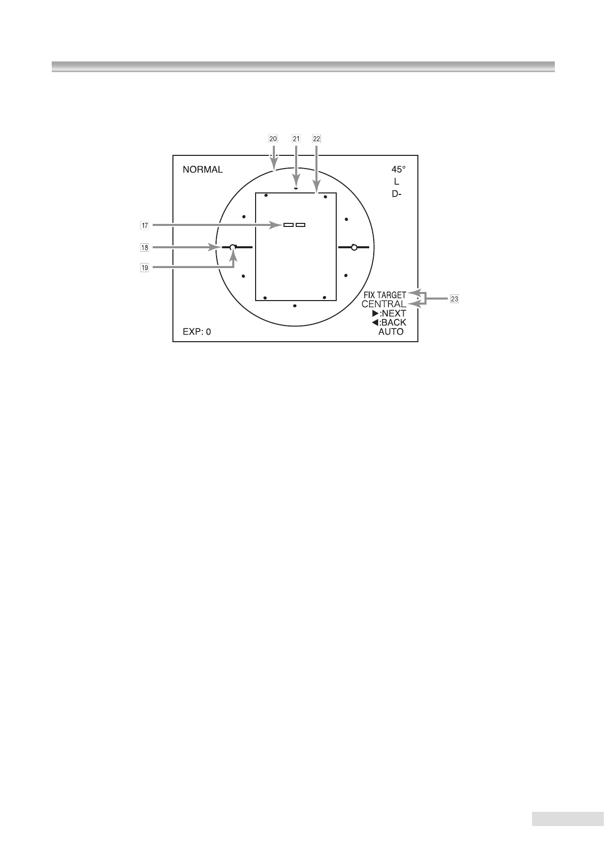
E Fixation target position
This indicates the xation target position currently turned on.
Normal, SP, and stereo modes
Posterior : CENTRAL
Optic disc : DISC
Center of macula : MACULA
External xation target : EXT
Mosaic mode photography
Internal xation target : AUTO/MANUAL
(this indicates the currently selected
position selecting method)
External xation target : EXT
F Completed mosaic mode photography
This indicates the completed photographing sequence
numbers or photographing positions in mosaic mode
photography.
AUTO :1a to 9a
MANUAL
:1 to 9
G Focus dots
These dots are shown optically for you to use as refer-
ence when focusing.
The dots appear when no diopter compensation is selected.
No dot appears when a + compensation or – compensa-
tion is selected.
H Retinal working dot position aids
These aids appear during retinal observation for you to
adjust the working dots.
No aid appears in mosaic mode photography.
I Working dots
These dots are shown optically for you to adjust the dis-
tance and position of a patient’s eye. No dot appears in
mosaic mode photography.
J Normal mode photographing range
This indicates the photographing range in normal mode.
K SP mode photographable range
This aid appears when SP mode is selected. It indicates
an approximate range where a clear image is captured.
L Stereo mode photographing range
This aid appears when stereo mode is selected and indi-
cates the photographing range in stereo mode.
M Eye xation direction and mosaic mode pho-
tography position
This indicates the guiding or alignment direction when the
internal xation target is used in mosaic mode photography.
“ FIX TARGET ” indicates the direction to which you guide
the patient’s eye xation.
Retinal observation display
K9L33 496B
注意
感電
警 告
ランプ、フラッシュランプ、
蛍光灯を交換する時は必ず
電源スイッチをOFF にし
て行ってください。
K9L33 496C
注意
高温
注 意
ランプ、フラッシュランプ、
蛍光灯の使用直後は熱くなって
いますので充分冷ましてから
交換してください。
USB cableTrigger cable
Power supply cable
Synchronous cable
All cables connected
Connect the cable with “
△
” mark facing to-
wards the LCD monitor of the digital camera.
k
9
2.1 Installing the system
1
Place the instrument on a powered optical table (optional accessory).
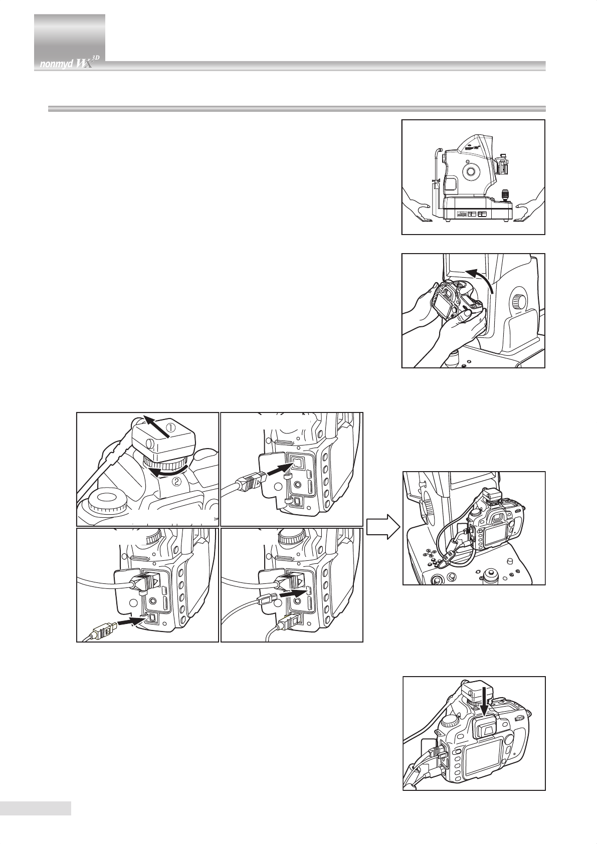
observe the following precautions when moving the instrument.
• Fasten the moving component xing screw.
• Put your hands under the power supply unit and lift the instrument as
shown in the right gure.
• Do not lift the instrument with holding any parts other than the above.
• Check the place where you are going to set the instrument is at with no
obstacle that may catch your hand.
• Be careful not to pinch your hand during installation.
2 Make sure that the power switch is in OFF (“q”) position.
3 Install the digital camera in the camera mount.
2 Installation
5 Ensure that an eye piece cap is attached to the viewnder of the digital
camera.
4 Connect the synchronous, power supply, trigger and USB cables to the
digital camera.
k
OFF
10
2.1 Installing the system
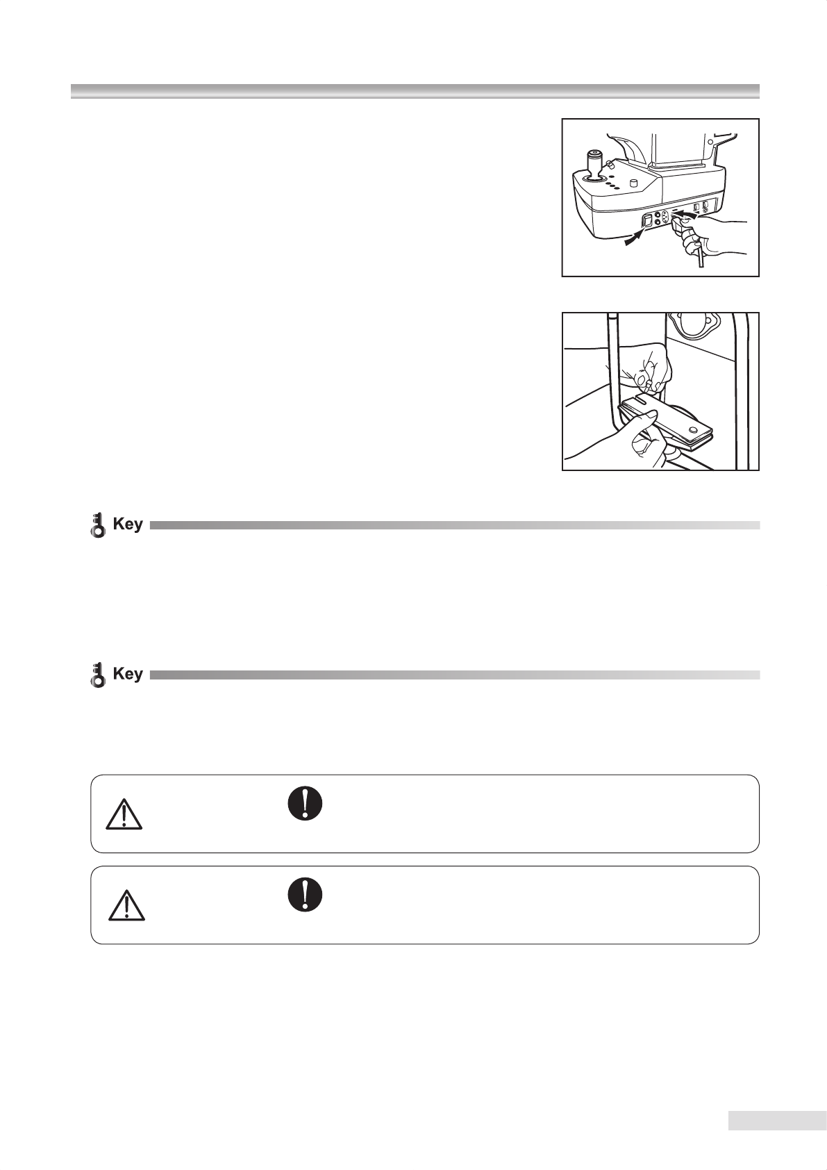
6 Make sure that the power switch is in OFF position.
Connect the power supply cable to the power supply cable connector.
Connect the power supply cable plug to a power outlet.
7
Place the chin rest paper on the chin rest and x the paper with the chin rest
paper retaining pin. Use a sheet of chin rest paper per patient. Remove the
top sheet of chin rest paper for the next patient.
x Do not connect a digital camera other than that supplied with this instrument.
x The digital camera is detachable: however, keep detaching/attaching the digital camera to the minimum in order
to prevent debris or dust from entering into the instrument and the digital camera.
x The digital camera needs to be disconnected from the instrument when the instrument is to be relocated or the in-
side of the digital camera is to be cleaned. In such a case arises, contact Kowa or your Kowa dealer in advance
for the correct procedures and precautions for detaching the digital camera.
x The digital camera supplied with this instrument is set for the retinal camera photography. Do not change the
setting.
x Do not detach the eye-piece cap from the digital camera.
x Do not disconnect the cables connected to the digital camera.
Warning
Obligatory
Make sure that the instrument is properly grounded to prevent
bodily injuries. Be sure to connect the plug into the three-wire
grounding type outlet with ground wire.
Otherwise, there may occur electrical shock.
Caution
Obligatory
The power supply must be provided for the sole use of the reti-
nal camera.
Sharing the same power supply with other devices may cause
malfunctioning.
11
2.2 Installing external device (optional PC)
Install a PC by following the PC’s instruction manual and turn it on.
Install the application software supplied with the PC. For details of installation, refer to “Installation manual (ling soft-
ware)”.
When you use a peripheral device and/or other device connected to the peripheral device, it must meet all applicable
EN(IEC) standards.
Data processing device must meet EN60601-1(IEC60601-1) or IEC60950. The system that combines such data
processing device must meet EN60601-1-1(IEC60601-1-1). The system administrator who builds such system bears
all responsibility to have the system comply with requirement of EN60601-1-1(IEC60601-1-1). Should you have any
question, contact Kowa sales representative or dealership.
2.3 Connecting PC
Connect the image output terminal (PC:Image) of this instrument to an USB terminal of the PC using the USB cable (Type
A-B) provided with the instrument.
Connect the imaging condition output terminal (PC: Data) of this instrument to the USB port of the PC using the USB
cable (Type A-Mini- B).
k For information on how to connect the instrument to the PC as well as the details of how to use the software, see the
attached “Installation manual (ling software)” and “User’s guide (ling software)”.
2 Installation
12
3 Saving captured images
Save captured images using the methods described in 3.1 or 3.2 below.
3.1
Saving captured images in PC (optional device)
Install the supplied ling software into the PC (optional device).
Use a USB cable supplied to connect a PC to the instrument. Captured images will be stored in the PC after it is con-
nected to the instrument.
About the PC
For details of the specication of the required PC, see the attached “Installation manual (ling software)” and
“User’s guide (ling software)”.
x Do not use any USB cable other than the supplied cable.
x Using other USB cable may inhibit normal operation.
k For information on how to connect the PC to the instrument as well as details of how to use the software, see the
attached “Installation manual (ling software)” and “User’s guide (ling software)”.
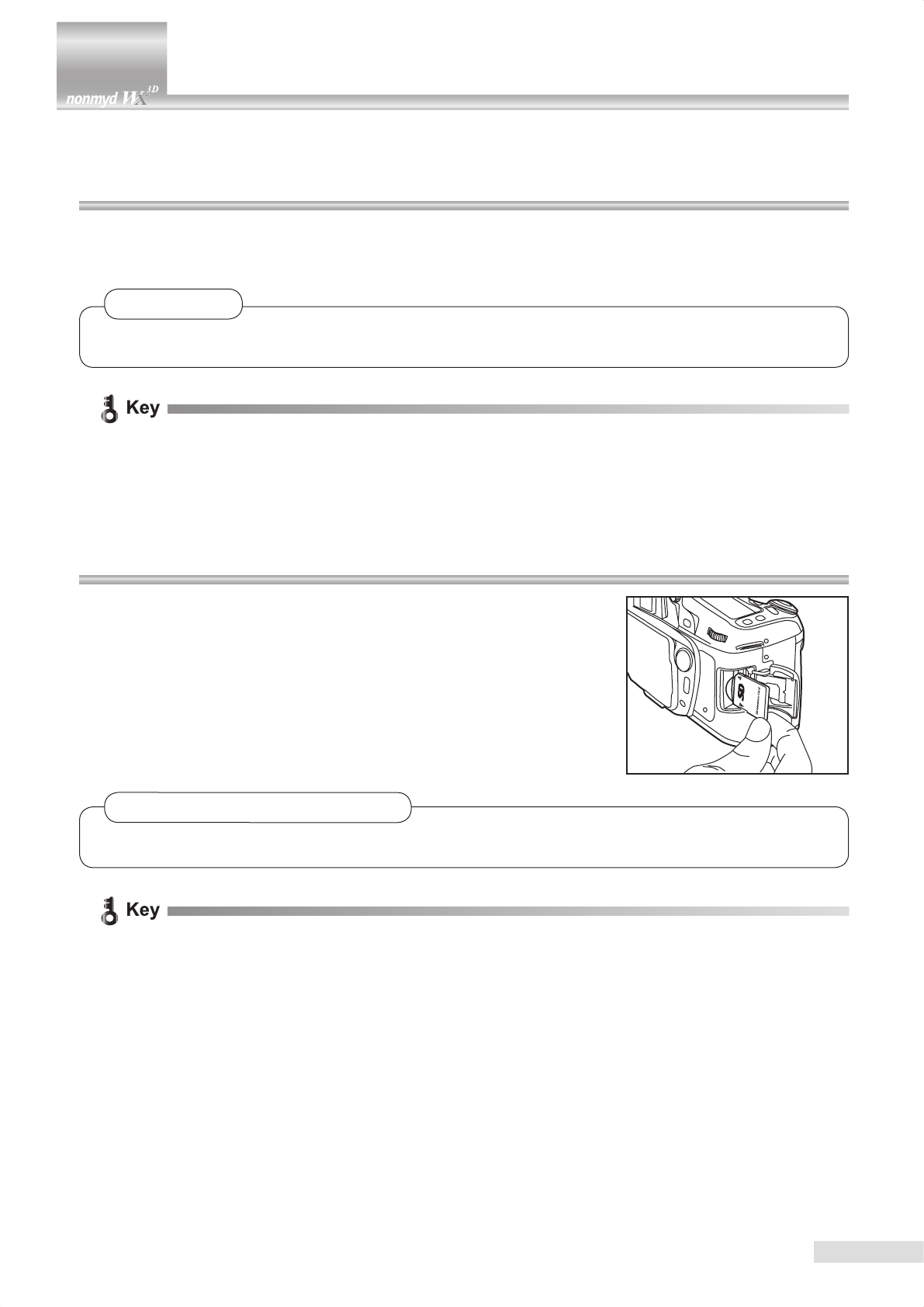
3.2 Saving captured images in a SD card
Insert a SD card into the digital camera.
Captured images will be stored in the SD card.
Captured images saved in a SD card
Captured images saved in a SD card may be displayed on the LCD monitor of the digital camera. The images may
be printed out connecting the digital camera to a printer. Contact Kowa or your Kowa dealer for details.
x The photographed images are not saved in the SD card when the instrument is connected with the PC.
loosen
tighten
13
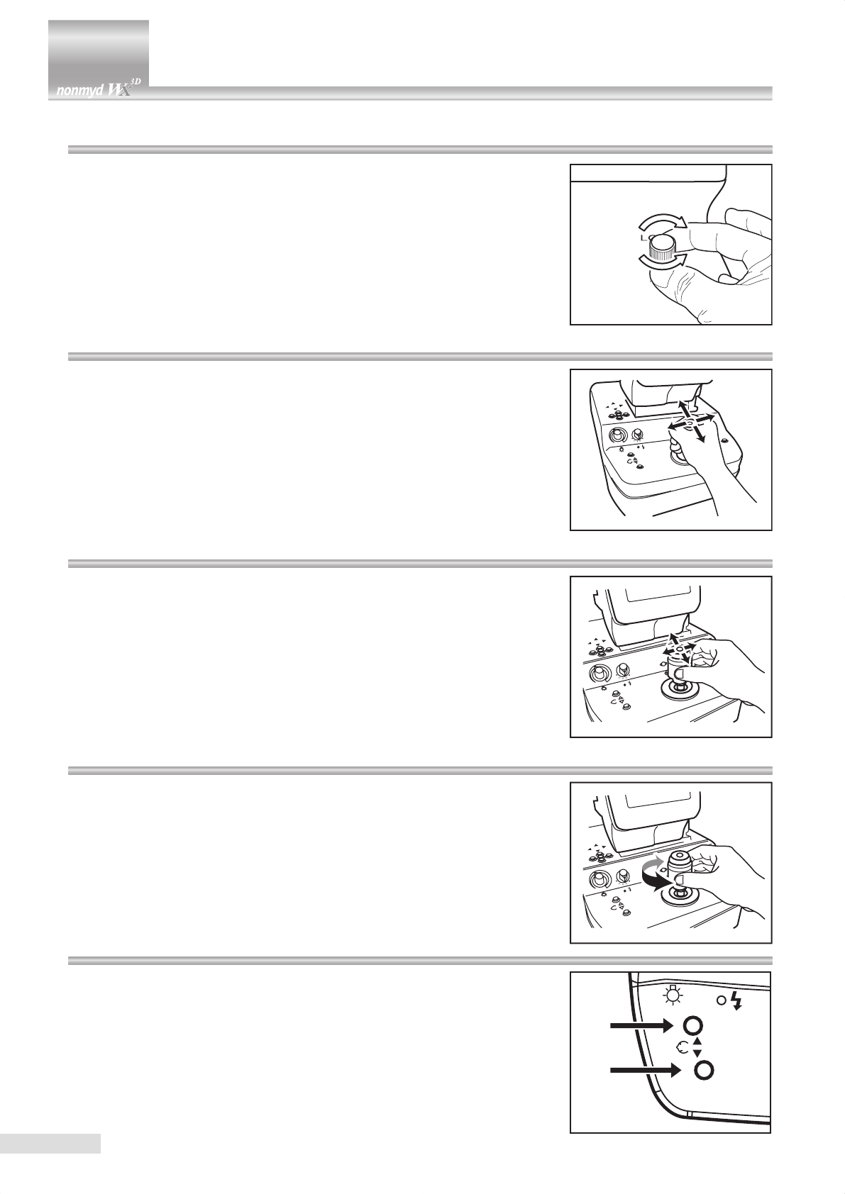
4.1 Moving component xing screw
Completely loosen the moving component fixing screw before starting any
photography using this instrument.
Completely tighten the moving component fixing screw before moving this
instrument to other installation site.
4.2
Coarse motion: moving the optical head base for a long distance
In order to move the optical head base for a slight distance, move the control
lever lengthwise or crosswise while holding the lever tightly in upright position.
4.3
Fine motion: moving the optical head base for a short distance
In order to move the optical head base for a very short distance, hold the
control lever gently and tilt it lengthwise or crosswise.
4.4 Raising and lowering the optical component
In order to move the optical component up and down, turn the rubber ring of
the control lever.
Turning the ring right moves the optical component up and turning left moves
the optical component down.
4.5 Raising and lowering the chin rest
In order to move the chin rest up, press chin rest raising button.
In order to move the chin rest down, press chin rest lowering button.
4 Basic operation
Retinal observation light intensity control knob Exposure compensation knob
Exposure compensation indicator
Diopter compensation knob
14
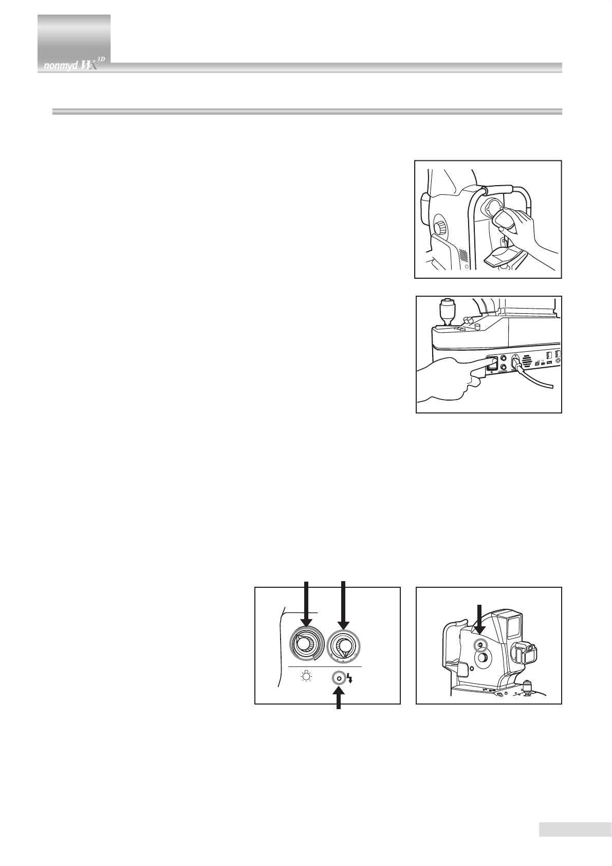
5.1 Preparing the instrument
1 Make sure that the moving component xing screw is completely loosened.
2 Make sure that the instrument is correctly connected to the PC.
Make sure that the PC is turned ON and the application software is started.
3 Remove objective lens cap.
4 Turn ON the power switch (place it in “ | ” position).
5 Make sure that retinal observation light intensity control knob, exposure compensation knob and diopter compensation
knob are in their initial position.
The initial positions for the knobs are as below
Retinal observation light intensity control knob : Approx. 10-o’clock position
Exposure compensation knob : 0 (The indicator under the knob turns OFF at the reference position.
When it is at a position other than the reference position, the indica-
tor illuminates.)
Diopter compensation knob : Pressed position. (“D+” or “D-” does not appear on LCD monitor
when it is in the initial position.)
5 Preparations for photography
Eye level mark
15
5.2 Preparations for patient’s eye examination
1 Reduce room’s illumination as bright as to make letters on this manual barely readable so that patient’s pupil can
naturally turn to the size of pupil diameter aid or greater.
2 Instruct the patient to take off his or her glasses or contact lenses.
3 Remove the top sheet of chin rest paper.
4 Move and keep optical component as close as possible to you and ask the
patient to rest the chin on chin rest.
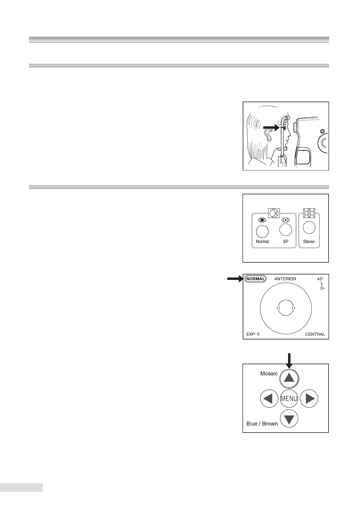
5 Adjust chin rest height until the patient’s eye level comes to the position of
eye level mark.
6 Instruct the patient to rest his or her forehead on forehead rest.
7 Adjust height of the table which this instrument is installed on so that the
patient can place his or her chin on chin rest with ease.
8 Adjust optical component height until it comes to the position of eye level
mark.
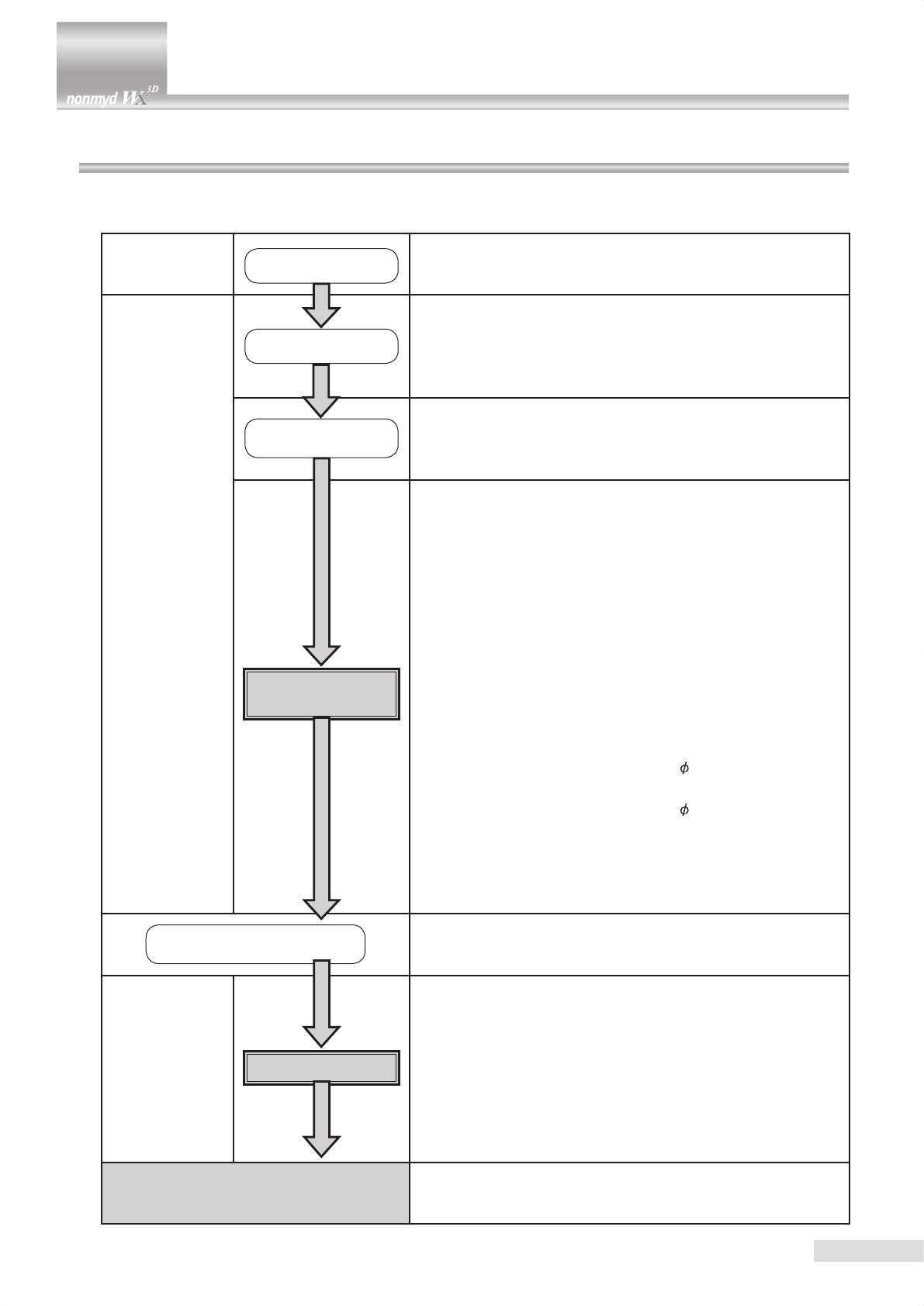
5.3 Selecting a photography mode
This instrument has “Normal mode”, “SP mode”, and “Stereo mode” for
photographing.
Press “Normal” button for normal photography, “SP” button for small pupil
photography, or “Stereo” button for stereo mode.
Upon activation of the instrument, “Normal mode” is selected.
The photography mode currently selected is indicated on the upper left
corner of LCD monitor.
This instrument also has mosaic mode photography for imaging the center
of macula and 8 points surrounding the macula. Press “Mosaic” button for
mosaic mode photography.
5 Preparations for photography
16
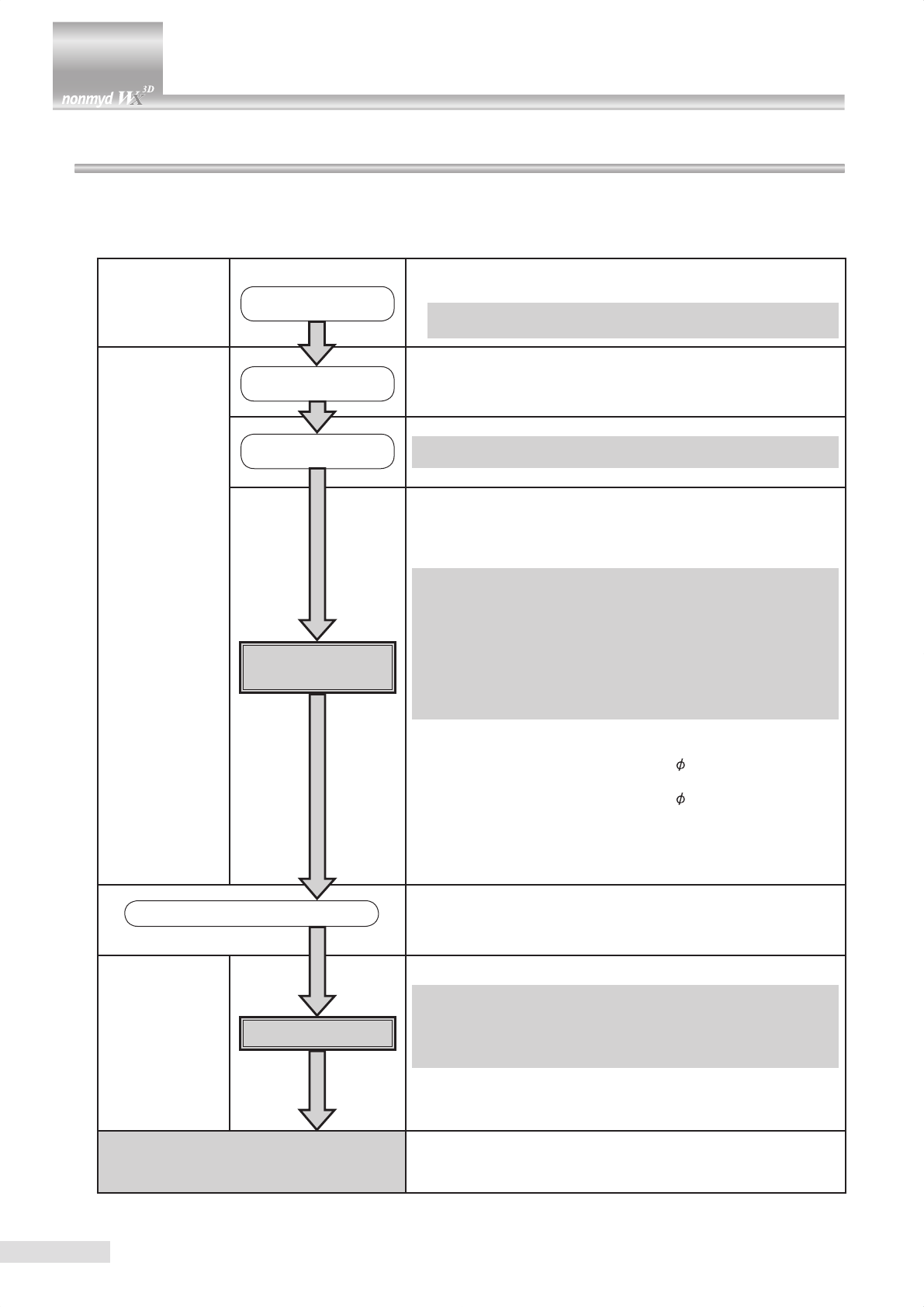
6.1 Normal, SP, and stereo modes
The chart shown blow describes the operation procedure in normal, SP, and stereo modes. Details of items shown in the
chart are described on the following pages.
Preparations for
photography
Turn ON the power
switch
] Preparing this instrument
] Preparations for patient’s eye examination
Anterior segment
observation
Selecting a photog-
raphy mode
1) Selecting a photography mode
Normal mode : NORMAL
SP mode : SMALL PUPIL
Stereo mode : STEREO
Selecting xation
target
2) Selecting an internal xation target
Normal or SP mode : Posterior (CENTRAL)
Stereo mode : Optic disc (DISC)
Anterior segment
alignment
3) Make sure that the instrument is currently showing the an-
terior segment observation display.
4) Guiding patient’s xation : Ask the patient to look at the
center of the xation target.
5) Aligning:
Move optical head base as close as possible to you.
Move optical head base leftward/rightward and move main
unit upward/downward to position the pupil image in the
center of the LCD monitor.
Move optical head base to place two working dots in the
anterior segment working dot position aids “( )” shown on
the center of LCD monitor.
6) Check the pupil diameter.
Normal or stereo mode (Normal pupil photography):
Pupil diameter: 4.0 mm or greater
SP
mode
(Small pupil photography):
Pupil diameter: 3.5 mm to 4.0 mm
7) Adjusting photography light intensity:
Change the photography light intensity depending on pupil
diameter.
8) Check that the eyelid is not intruding the pupil area.
Switching to Retinal
observation display
9) Press anterior segment button to switch to retinal observa-
tion.
Retinal observation Retinal alignment
10) Adjust the observation light intensity.
11) Guide the patient’s xation.
12) Aligning:
Move optical head base to place two working dots on the
top of the left and right bars in the middle of LCD display.
13) Focusing:
Turn focusing knob to have two focus dots on the display
to form a single line.
Photography 14) Photography: Press shutter button to photograph.
6 Operational procedure in photography

17
6.1.1 Selecting a photography mode
Select a photography mode by pressing “Normal”, “SP”, or “Stereo” button.
Check that the mode you have selected is shown on the upper left corner of LCD monitor.
Normal mode SP mode Stereo mode
6.1.2 Selecting an internal xation target
Use internal xation target selection button to select an internal xation target
that you use for retinal observation.
Continuously pressing the button cycles through the targets as shown in the
gure below.
(Cyclic order of internal xation targets)
Posterior Optic disc Macula
(CENTRAL) (DISC) (MACULA)
When the photography mode is switched, “CENTRAL” is selected for normal or SP mode while “DISC” is selected for
stereo mode. The internal xation target you have selected appears on the lower right corner of LCD monitor.
(See the gures of normal, SP, and stereo modes shown in “6.1.1 Selecting a photography mode”.)
6 Operational procedure in photography
18
6.1 Normal, SP, and stereo modes
6.1.3 Checking anterior segment observation display
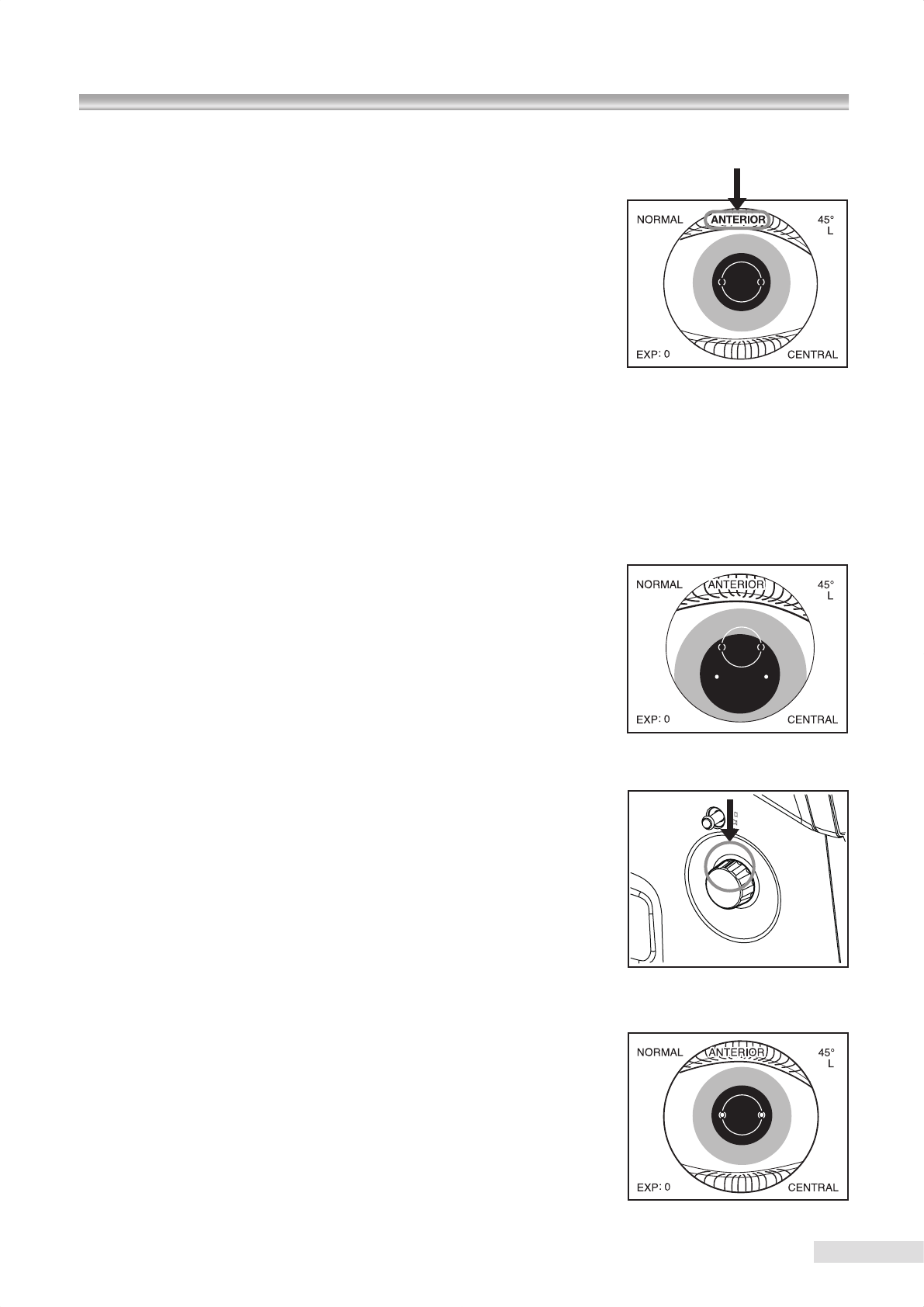
Make sure that “ANTERIOR” is shown in the upper part of LCD monitor.
Press anterior segment button when “ANTERIOR” is not shown.
6.1.4 Guiding patient’s xation
Instruct the patient to look straight ahead.
Perform the step described in “6.1.5 Alignment”. Ask the patient to look straight ahead at the green illuminating spot
when the patient’s pupil becomes shown in the center of LCD monitor.
When failed to complete the patient’s xation by using the internal xation target, use the external xation target (
optional
accessory:
K9L-LE57). Refer to “7.2 external xation target” for details of connecting and operating the external xation
target.
6.1.5 Aligning
Pull the optical component as close as possible to you and move the optical
head base leftward/rightward or upward/downward in order to capture the
pupil at the center of the LCD monitor.
Rotate focusing knob until the black line engraved on the knob faces upwards.
After the pupil image is captured successfully, move the optical head base
forward until two working dots come in two pairs of round brackets “( )”.
Beginning of alignment
Focusing knob position
Alignment completed
Exposure compensation knob
19
6.1.6 Checking pupil diameter
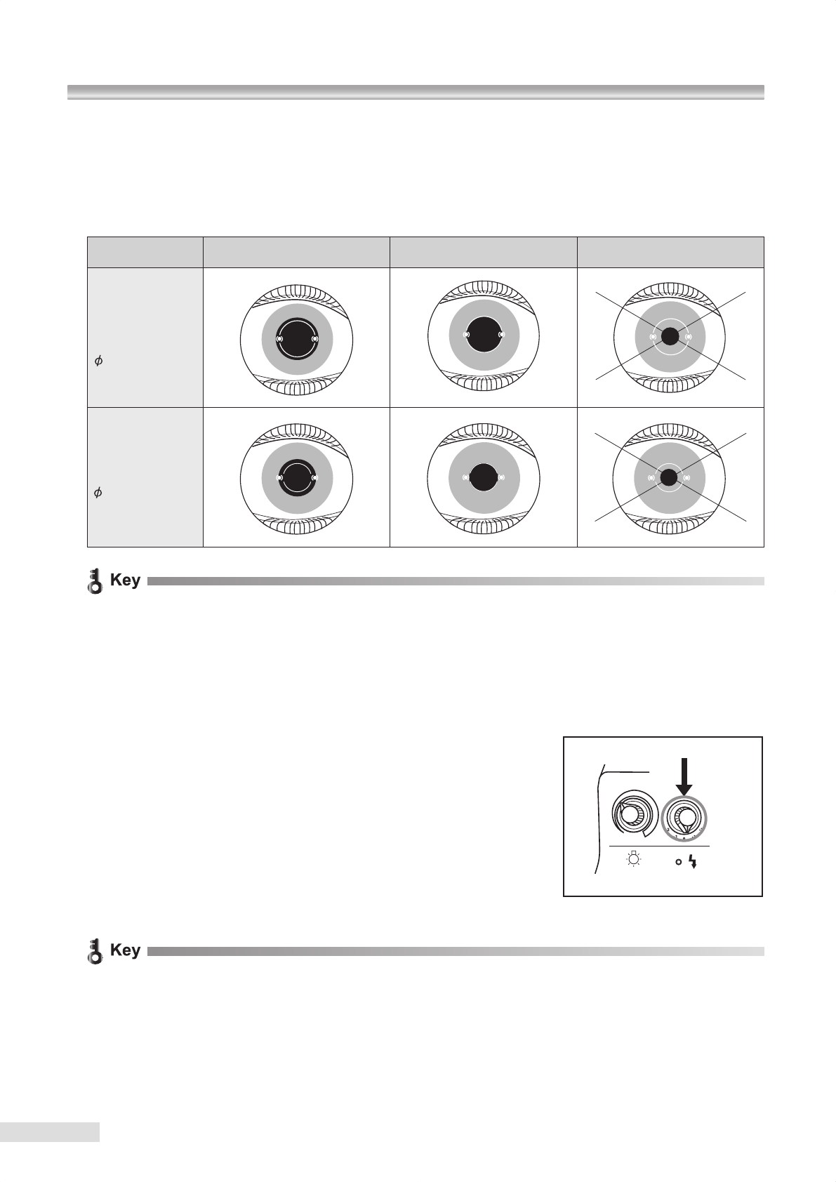
Check the condition of dilation by comparing the patient’s pupil diameter against the pupil diameter aid.
Change the photography light intensity as required depending on the mydriatic state.
If the patient’s pupil diameter is smaller than that shown by the pupil diameter aid, press SP mode button to proceed to
small pupil photography.
Photography light
intensity
0 +1 Insufcient for photography
Normal mode
Stereo mode
Pupil diameter:
4 mm or greater
SP mode
Pupil diameter:
3.5 mm to 4 mm
x In case of the above insufcient for photography, make the room darker, or take more time to get accustomed to
darkness so that the pupil’s dilation can be facilitated.
x It would be difcult to capture a clear image when the pupil diameter is insufcient. However it may not be appli-
cable to some patients.
6.1.7 Adjusting photography light intensity
Change the photography light intensity by the exposure compensation knob
as needed depending on the condition of dilation.
x The photography light intensity is automatically set to the standard level sufcient for each photographing pro-
cedure. However, each patient’s mydriatic state and iris color may cause excessive or insufcient light intensity.
When excessive or insufcient light intensity occurs, use exposure compensation knob to compensate the inten-
sity. The LCD monitor shows the current light intensity setting as a guideline. Rotating exposure compensation
knob to one step up or down changes 1/2 step of exposure value.
6 Operational procedure in photography
anterior segment button
20
6.1 Normal, SP, and stereo modes
6.1.8 Checking eyelids and eyelashes
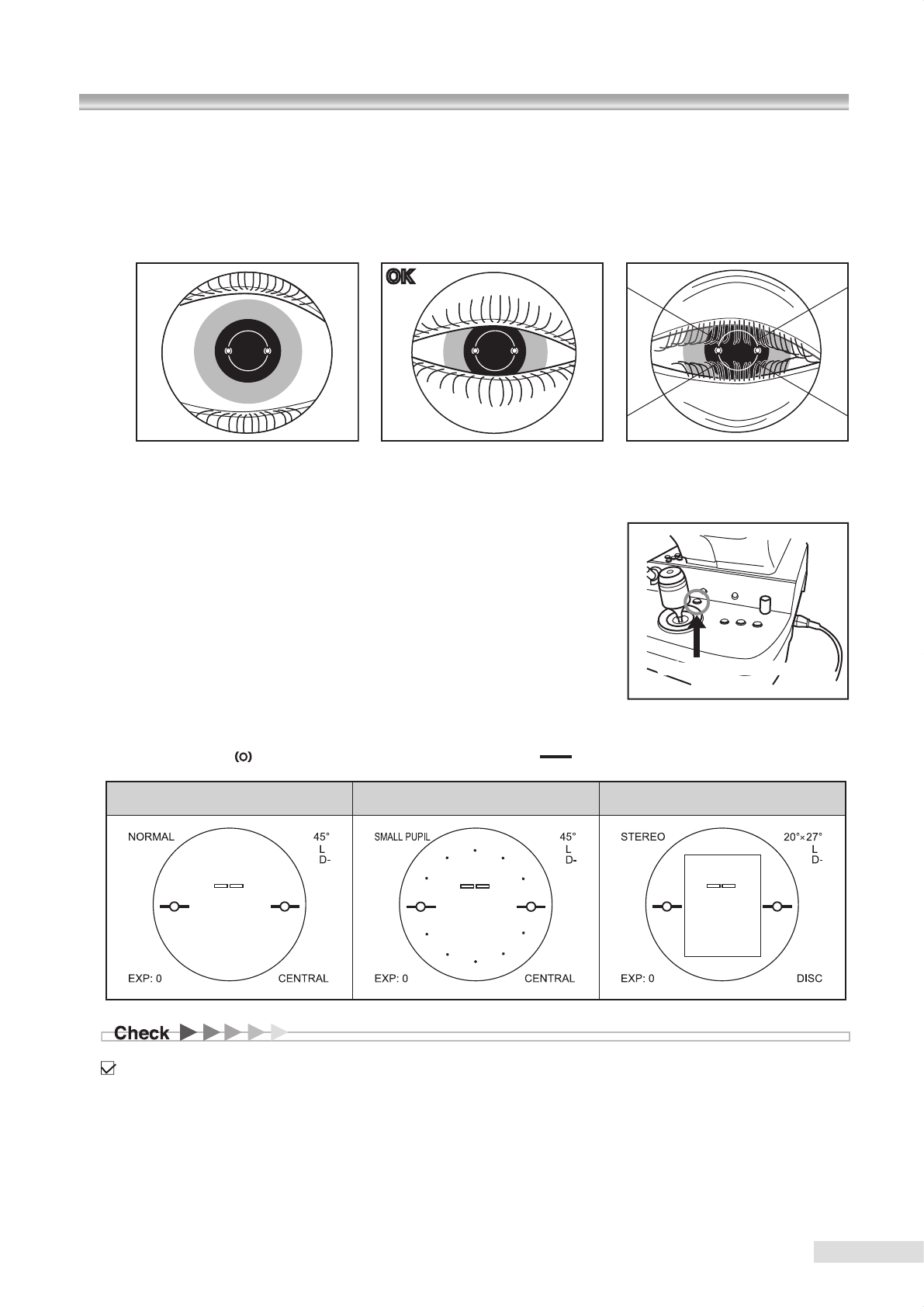
The eyelids or eyelashes intruding the pupil area interferes photography.
In such a case,
• Instruct the patient to widely open his or her eyes, or
• You or your assistant help the patient keep the eye wide open.
OK NGOK
6.1.9 Switching from anterior segment observation to retinal observation
After alignment of the anterior segment is completed, press anterior segment
button to switch to retinal observation.
When you want to go back to anterior segment observation, press the button
again.
“ANTERIOR” and the pupil diameter aid of the LCD monitor disappear during retinal observation. Anterior segment work-
ing dot position aids “ ” changes to retinal working dot position aids “ ”, and the focus dots appears.
Normal mode SP mode Stereo mode
For stereo mode observation, move the photography target to the center of the LCD monitor.
Retinal observation light intensity
control knob
Right eye Left eye
Posterior Near center
Optic disc Left Right
Center of
macula Center
Working dot
Retinal work-
ing dot posi-
tion aid
Focus dots
21
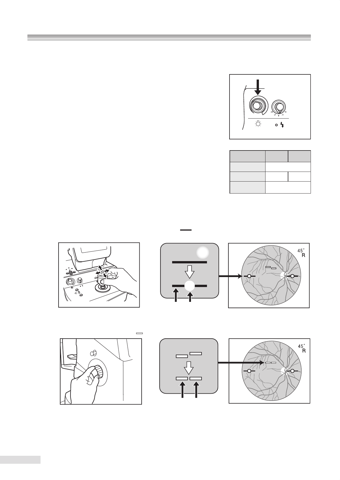
6.1.10 Adjusting observation light intensity
Adjust the image brightness by retinal observation light intensity control knob
when the retinal image, focus dots, and working dots are not clearly shown.
For details of LCD monitor brightness and contrast adjustment, refer to “9.4.6
MONITOR BRIGHTNESS / CONTRAST”.
6.1.11 Guiding patient’s xation
The fixation target position changes when anterior segment observation is
switched to retinal observation. In order for the patient to stare at the selected
internal xation target, guide the patient’s xation to the internal xation target
by asking the patient to look at the green light.
Patients would recognize the xation target at the locations shown in the right
table depending on whether the right or left eye is examined and which xation
target position is selected.
6.1.12 Aligning
Move the optical head base slightly until the sizes of the two working dots become the smallest and the dots are aligned
on the top of the left and right retinal working dot position aids “ ” in the LCD monitor as shown in the gure below.
The focus of the two working dots may be ne tuned by moving the control lever forward/backward.
6.1.13 Focusing
Turn focusing knob to have two focus dots “ ” on the display to form a single line.
6.1.14 Photography
After alignment and focusing are completed, photograph by pressing shutter button.
Pictures will be stored in the connected PC. For viewing and analyzing the pictures using a PC, refer to “Installation
manual (ling software)”.
6 Operational procedure in photography

22
6.1 Normal, SP, and stereo modes / 6.2 Precaution for continuous photography / 6.3 Terminating photography
6.2 Precautions for continuous photography
Please note that the LCD monitor automatically switches back to anterior segment observation. *3 When you continue
photographing, note the precautions described below.
k3 You may disable the anterior segment observation auto-return function by changing the setting.
For details of the setting, refer to “9.4.4 EXTERNAL ALIGNMENT:NORMAL” and “9.4.5 EXTERNAL ALIGNMENT:
MOSAIC”
6.2.1 Pupil diameter
When you continuously photograph, the pupil is constricted due to the ash light in the previous photography. In such a
case, wait for a while and make sure that the pupil diameter is sufcient for photography.
6.2.2 Photographing the other side of eye
When continuously photographing the other side of the eye, pull optical head base toward you so that it will not contact
the patient’s eye or nose and then move the digital camera toward the other side.
x Do not increase the photography light intensity more than required.
Otherwise the patient may experience pain and his or her eye may be injured.
6.3 Terminating photography
•
Turn OFF the power switch of this instrument (place it in “q” position), exit the ling software, and turn OFF the PC. Refer
to “Instruction manual (ling software)” or the PC’s “Instruction manual” for how to terminate the PC.
• Place the lens cap on the objective lens.
• Move optical head base back to initial position where optical head base is positioned just above the power supply and
x it there by tightening the moving component xing screw.
• Place the dust cover over the
instrument
.
23
7.1 Mosaic mode photography
Mosaic mode photography has its own internal xation target selection and positioning different form that of Normal or SP
mode.
In this section only these differences are described.
Preparations for
photography
Turn ON the power
switch
k Preparing this instrument
k Preparations for patient’s eye examination
k Press mosaic button and check that “MOSAIC” appears
on LCD monitor.
Anterior segment
observation
Checking the selected
photography mode
1) Checking the photography mode
Normal mode : NORMAL
SP mode : SMALL PUPIL
Selecting a xation
target 2) Selecting an internal xation target
Anterior segment
alignment
3) Make sure that the instrument is currently showing anterior
segment observation display.
4) Guiding patient’s xation : Ask the patient to look at the
center of the xation target.
5) Alignment:
Move optical head base as close as possible to you.
Move optical head base leftward/rightward and move
optical component upward/downward to position the
pupil image in the center of the LCD monitor.
Move optical head base to place two working dots in
the anterior segment working dot position aids “( )”
shown on LCD monitor.
6) Check the pupil diameter:
Normal mode (Normal pupil photography)
Pupil diameter: 4.0 mm or greater
SP mode (Small pupil photography):
Pupil diameter: 3.5 mm to 4.0 mm
7) Adjusting the light intensity:
Change the photography light intensity depending on pu-
pil diameter.
8) Check that the eyelid is not intruding the pupil area.
Switching to retinal observation 9) Press anterior segment button to switch to retinal observa-
tion.
Retinal observation Retinal alignment
10) Adjust the observation light intensity.
11) Guide the patient’s xation.
12) Alignment:
Position optical head base in the place where you
can obtain the retinal image most clearly.
13) Focusing:
Turn focusing knob to have two focus dots on the display
to form a single line.
Photography 14) Photography: Press shutter button to photograph.
7 Advanced photography
24
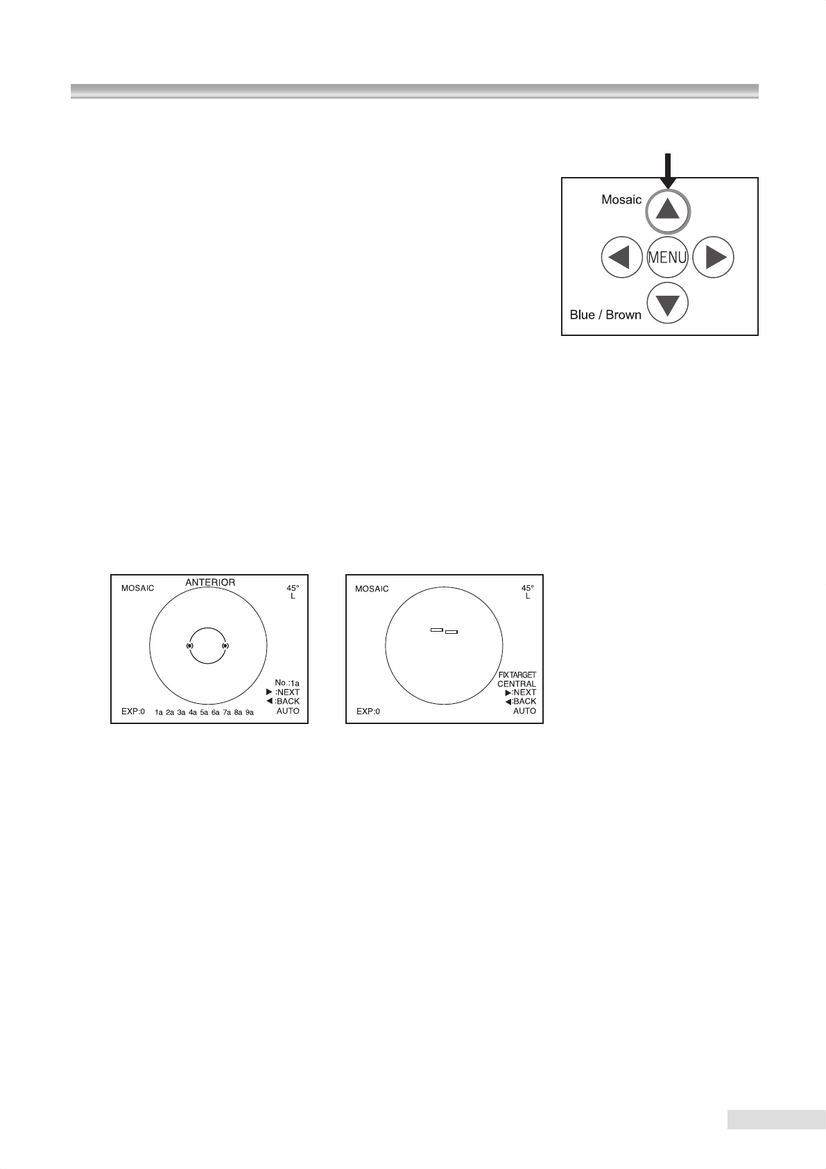
7.1.1 Selecting mosaic mode photography
Press mosaic button (the button above “MENU” button).
You can switch between Normal mode and SP mode during mosaic mode
photography.
7.1.2 Selecting an internal xation target
Internal xation target selection button becomes disabled during mosaic mode photography. Mosaic mode photography
has two types of internal xation target setting methods, “AUTO” and “MANUAL” settings.
In “Auto mode setting”, one of the internal xation targets is sequentially selected in the predened order.
In “Manual setting”, an internal xation target is selected manually by pressing one of the keys corresponding to the pho-
tographing parts of the eye.
The default setting is “Auto mode setting”.
For changing the setting, refer to “9.3 Mosaic internal xation target setting (Switching internal xation target in
mosaic mode photography)”.
L Switching the internal xation target in mosaic mode photography – Use in auto mode
Anterior segment observation display Retinal observation display
The position of the anterior segment working dot position aids on anterior segment observation display changes
depending on the photographing part of the eye.
In auto setting, one internal xation target is automatically switched to another after completing each photography and
the corresponding photographing part of the eye is also changed consequently.
When you want to photograph again because of poor photo quality, press the left key of the menu buttons.
The internal xation target that corresponds to the last photographing part illuminates.
When you do not need to photograph the area currently selected, press the right side button of the menu button. This
switches the current part to the next photographing part and the internal xation target that correspond to the next
photographing part illuminates.
1a to 9a shown on the bottom of LCD monitor indicate the mosaic mode photography sequence selected in menu
mode. When a photograph is taken, the corresponding number becomes highlighted. Pressing shutter button by
mistake while observing anterior segment does not allow the next photographing part to appear since an image
capturing must be repeated again.
For details of the mosaic mode photography sequence setting, refer to “9.3.2 Setting of auto mode”.
7.1 Mosaic mode photography
0 00
1 2 3
4 5 6
7 8 9
BS
Enter
Num
Lock /
Optional accessory
25
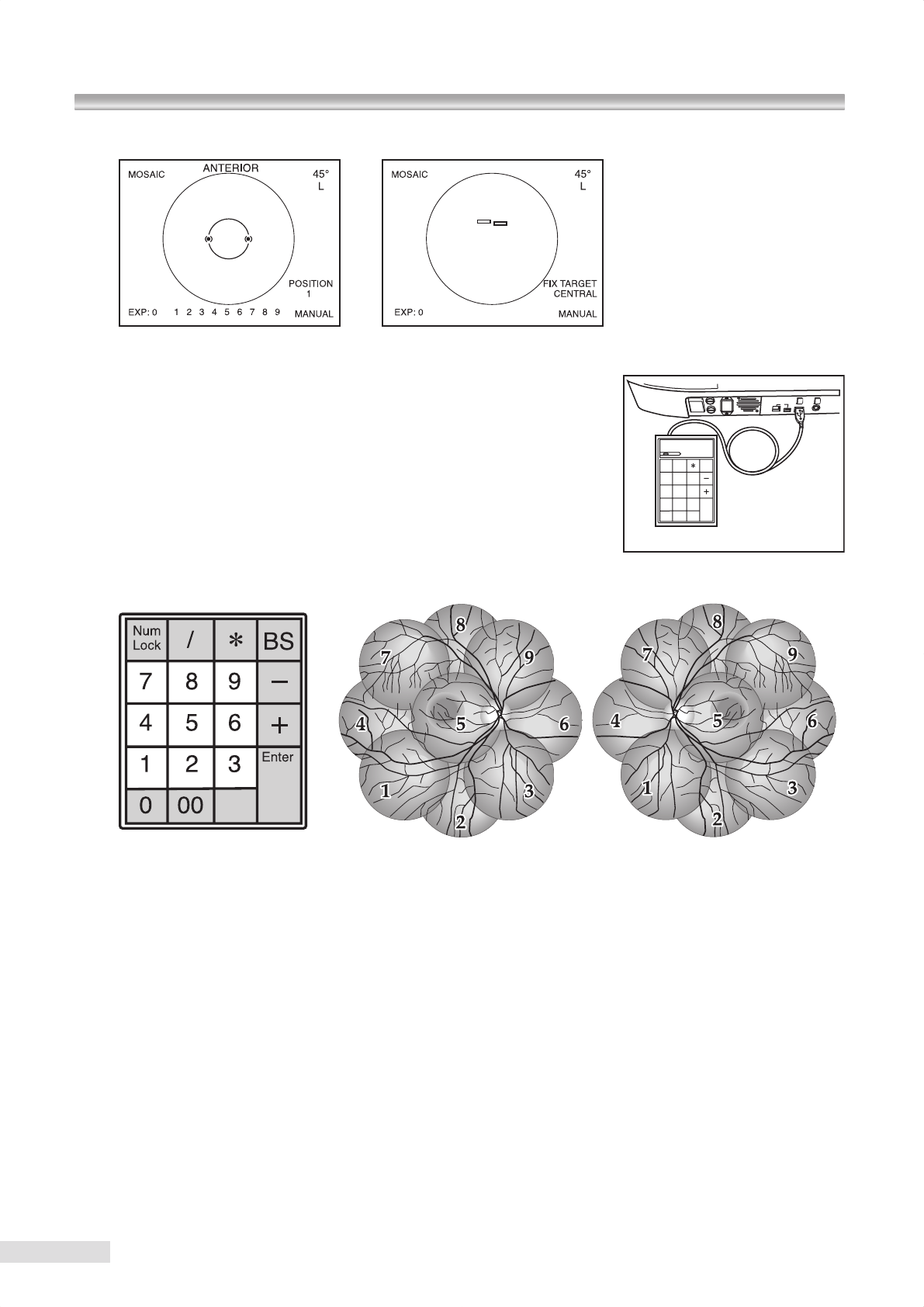
L Switching the internal xation target in mosaic mode photography – Use in manual mode
Anterior segment observation display Retinal observation display
Select manual mode in order to select the photographing parts of your
choice in mosaic mode photography.
g For details of the setting, refer to “9.3 Mosaic internal fixation
target setting (Switching internal fixation target in mosaic mode
photography)”. Connect a numerical keypad (optional accessory) that
allows you to select internal xation target positions of your choice.
Turn ON num lock of the connected numerical keypad.
Keys of a numerical keypad are used to select internal fixation target positions in manual setting. Relationship
between the keys and the internal xation target positions is shown below.
Keys of numerical keypad Right eye Left eye
(Shaded keys are invalid.)
The numbers from 1 to 9 that appear on the bottom of the display indicate photographing parts of the eye (and keys
of numerical keypad). When a photograph is taken, the corresponding number becomes highlighted.
The highlighting is cleared when the optical head base is moved to switch the eye to be examined to the other side of
eye.
7 Advanced photography
26
7.1 Mosaic mode photography
7.1.3 Aligning and focusing
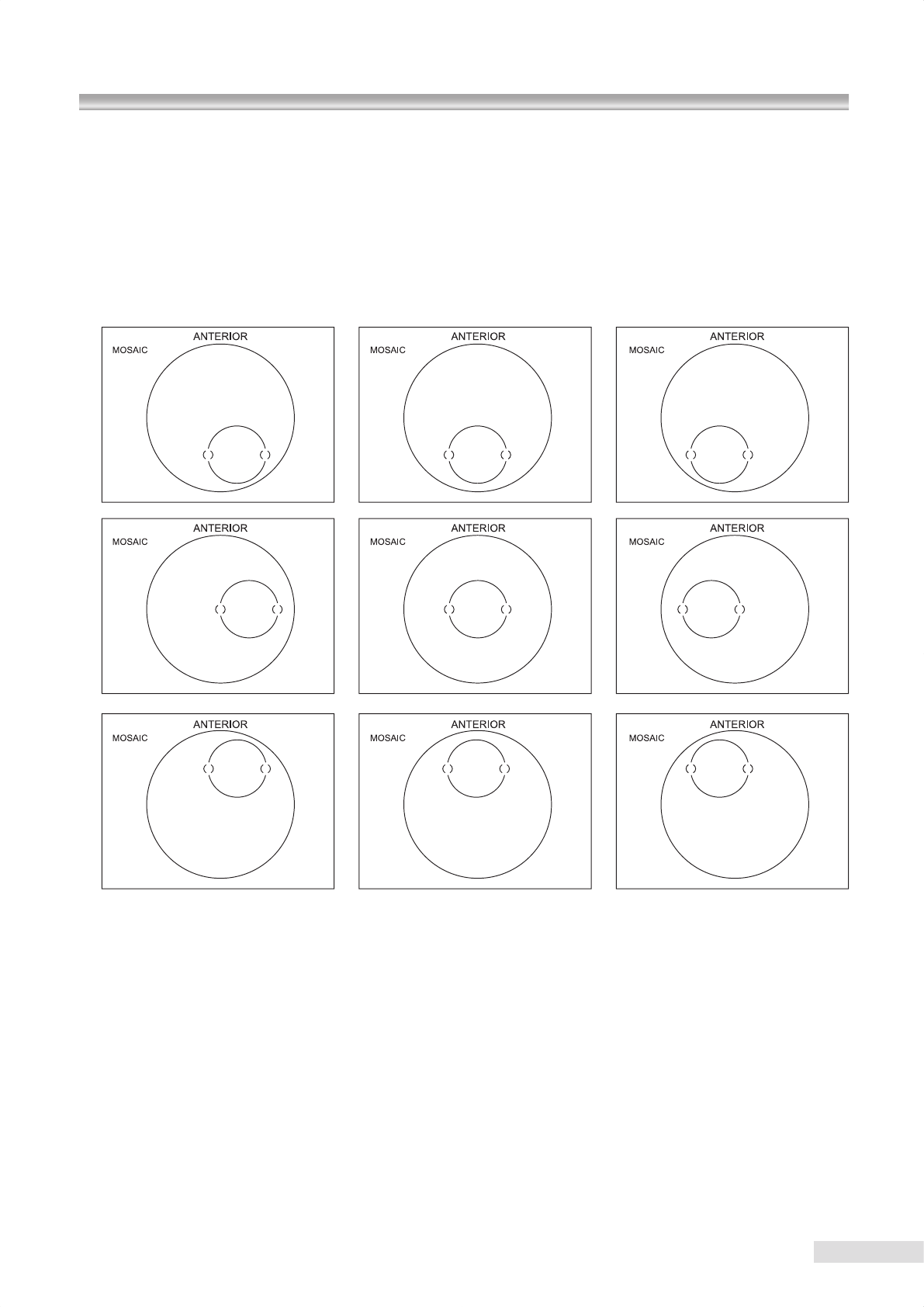
In mosaic mode photography, align for anterior segment observation only, switch to retinal observation without changing
the position of the instrument, check that the patient eye is correctly xed, and photograph.
However when you see an excessive are during retinal observation, position the digital camera appropriately before
photographing.
For mosaic mode photography, the alignment position in anterior segment observation appears in different positions as
shown in the gures below. Align appropriately so that the working dots t within the anterior segment working dot posi-
tion aids.
“FIX TARGET” that indicates the eye xation direction for you to direct a patient or the position of the internal xation tar-
get visible from a patient appears on the lower right of LCD monitor during retinal observation.
Tell the patient the direction shown on the display and guide the patient’s xation.
Please note that some photographing parts may not clearly show the focus dots. In such a case, perform focusing using
macula and photograph other photographing parts without re-focusing. However you may re-focus when you can see the
focus dots clearly.
k4
27
7.2 External xation target
When failed to complete xation of the patient’s eye using the internal xation target, use the external xation target (op-
tional accessory: K9L-LE57) to enable the xation using the other eye.
7.2.1 Installing the external xation target
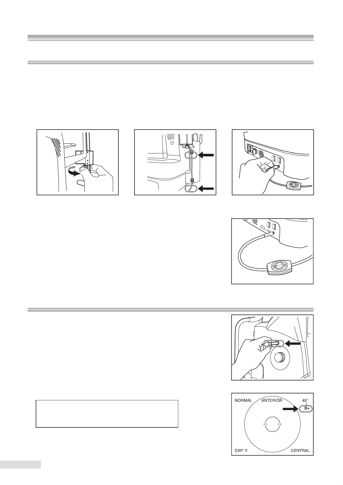
1
Aligning the groove on the external xation target mount and the chin rest, tighten two mounting screws to lock the lamp.
2 Adhere attached cable clamps at two places shown in the gure and x the cable with the cable clamps.
3 Insert the cable into the external xation target connecting terminal.
7.2.2 Using the external xation target
The external xation target illuminates by turning on the button installed on
the cable.(When it is turned ON, the internal xation target turns OFF.) “EXT”
appears on the lower right corner of LCD monitor when the external xation
target is in use.
7.3 Diopter compensation range
When clear focus can not be obtained by focusing, pull out diopter
compensation knob.
Pulling out diopter compensation knob to the first stop enables the minus
diopter compensation (D-) while pulling out to the second stop enables the
plus diopter compensation (D+). Slowly pull out the knob until it cricks when it
comes into one of the diopter lens insert positions. When you stop pulling the
knob before it cricks, you can not obtain a good image.
The minus or plus diopter compensation is indicated on the upper right corner
of LCD monitor.*4
The focusing range of each compensation position is shown below.
No diopter lens
−
12 m-1(D) to +13 m-1(D)
Plus diopter compensation + 10 m-1(D) to +35 m-1(D)
Minus diopter compensation
−
32 m-1(D) to
−
10 m-1(D)
Adjust the focus using the retinal image on the LCD monitor since focus dots
do not appear when diopter compensation lens is in use.
12 3
7 Advanced photography
28
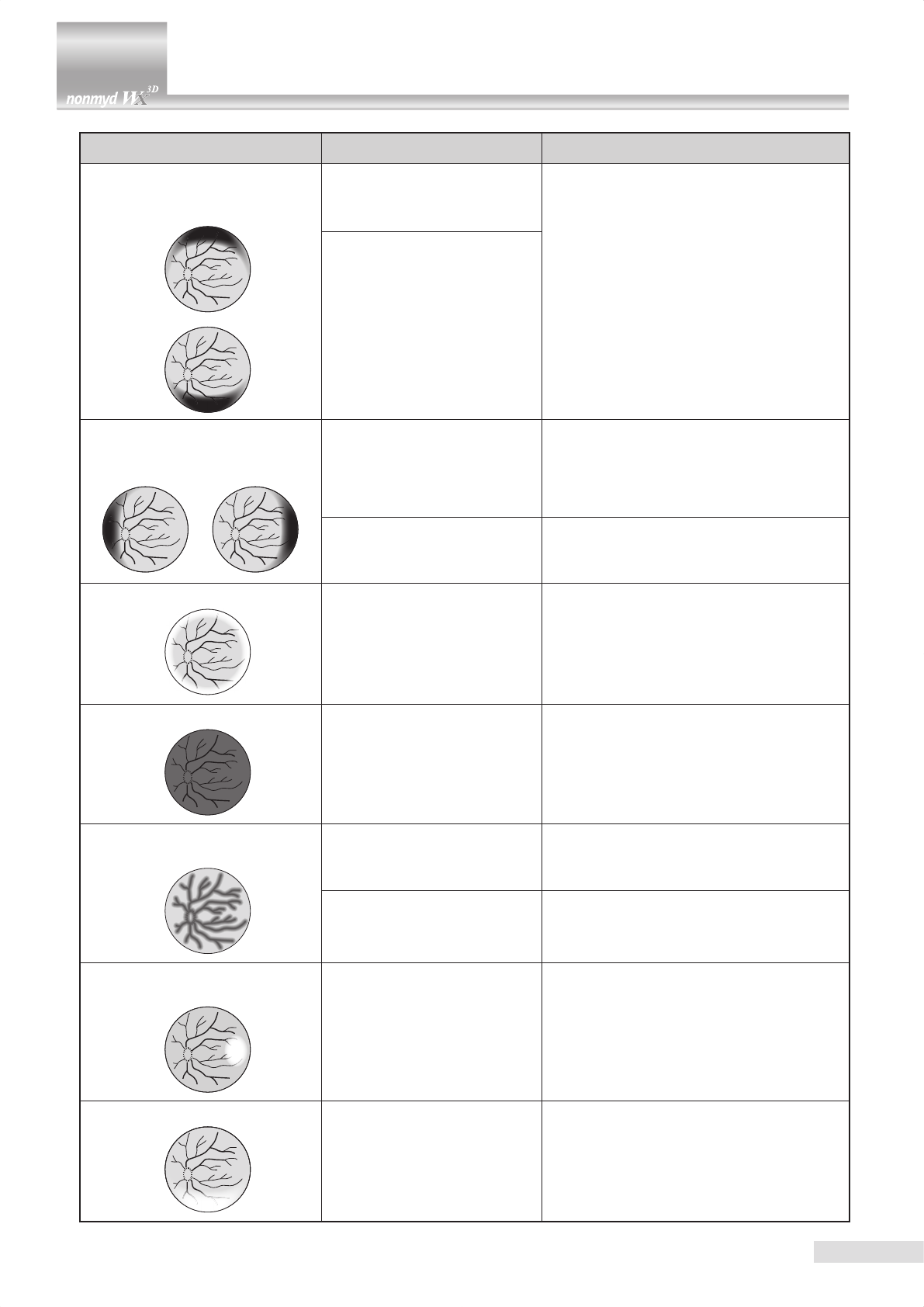
Examples of retinal photograph Possible cause Remedies
Dark shadow or bright reflection
appears at the top or bottom of the
image.
The instrument is positioned
too high to the patient’s eye.
Perform all alignment steps to obtain a clear
retinal image with consistent brightness. De-
pending on the patient’s eye fixation condi-
tion, you may obtain a good image by locating
working dots away from the dot position aid.
The instrument is positioned
too low to the patient’s eye.
Dark shadow or bright reflection
appears at the left or right of the
image.
The instrument is positioned
too right or left to the patient’s
eye.
Perform all alignment steps to obtain a clear
retinal image with consistent brightness. De-
pending on the patient’s eye fixation condi-
tion, you may obtain a good image by locating
working dots away from the dot position aid.
Diopter compensation knob is
not in click.
Check that diopter compensation knob is in
the correct position by slowly moving the knob
to see if it cricks.
Peripheral area become whitened.
The instrument is positioned
too close to the patient’s eye.
The instrument is positioned
too far from the patient’s eye.
Locate the digital camera to the position
where working dots become smallest. When
flares still persist, pull the digital camera a
little or move the optical component to the
patient. (Working dots may be fades a little.)
The image is too dark.
The pupil diameter is small.
Turn exposure compensation knob to +1 or
+2 position. If the patient’s pupil diameter
equal to or smaller than that shown by the
working dots, press SP mode button and
photograph in SP mode.
The i m a ge is o u t of f o c us or
blurred. The patient has developed a
cataract.
Avoiding the area of white turbidity during
alignment may allow you to obtain a good im-
age.
The corneal surface is dry. Ask the patient to blink before imaging.
The image become whitened lo-
cally.
The objective lens is dirty.
Clean the objective lens.
Refer to “10. Maintenance and inspection”
for details of the objective lens cleaning.
The lower area become whitened.
The eyelid or eyelashes intrude
the imaging area.
Ask the patient to open his/her eyes wide so
that the eyelid or eyelashes do not intrude
the area of the pupil, or you or your assistant
help the patient keep the eye wide open.
8 Troubleshooting
29
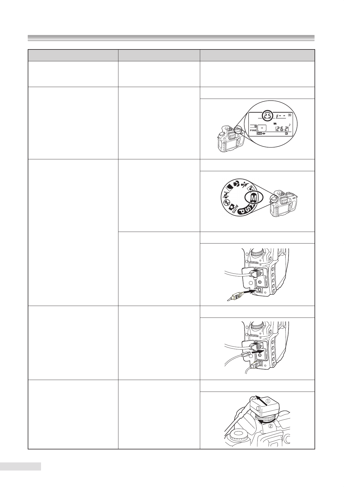
Irregularity Possible cause Remedies
Focus dots do not appear. A diopter compensation lens is
inserted.
Adjust the focus using the retinal image since
focus dots do not appear when a diopter com-
pensation lens is in use.
The ash lamp turns on but a black
image or partially chipped image is
obtained.
The shutter speed of digital
camera is not set to 1/25 sec.
Set the shutter speed of digital camera to 1/25 sec.
The flash lamp does not turn ON
and no image is captured.
The digital camera is not set to
manual mode.
Set the digital camera to manual mode.
Trigger cable is not fully insert-
ed.
Fully insert the trigger cable to the end.
Although image are successfully
captured and shown on the LCD
monitor of the digital camera, the
monitor of the PC presents no im-
age.
The USB cable is not fully in-
serted.
Fully insert the USB cable to the end.
Images are captured without flash
lamp turned on.
The synchronous cable is not
fully inserted.
Fully insert the synchronous cable to the end.
8 Troubleshooting
k
Refer to “12 Technical information”.
k
Refer to “12 Technical information”.

30
8 Troubleshooting
Irregularity Possible cause Remedies
The error message below is dis-
played on the LCD monitor.
ERROR 1 : HIGHER VOLTAGE
POWER OFF AND CALL SER-
VICE PERSON
Charged voltage exceeded the
limit. There could be a failure
of an internal circuit.
Please contact Kowa or your Kowa dealer.
The error message below is dis-
played on the LCD monitor.
ERROR 2 : LOWER VOLTAGE
POWER OFF AND CALL SER-
VICE PERSON
Charged voltage does not
reach the lower limit. There
could be a failure of an internal
circuit.
Please contact Kowa or your Kowa dealer.
The error message below is dis-
played on the LCD monitor.
NOW COOLING
PLEASE WAIT 120 SEC
Cooling has been started since
the recharge circuit tempera-
ture exceeded the higher limit.
This is not a malfunction. Wait for 120 sec-
onds before you resume photography.
Menu buttons
31
9 Menu operation
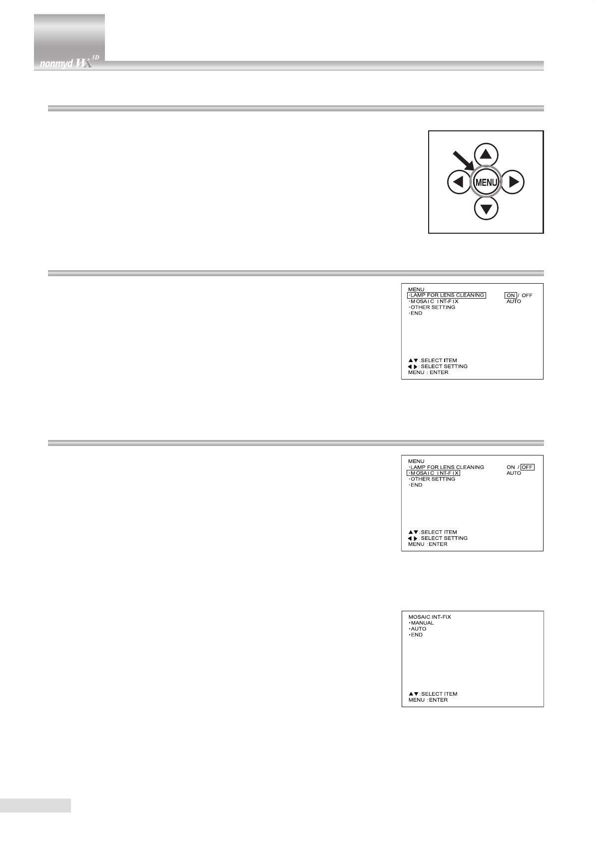
9.1 Starting menu
Press down “MENU” button center of menu buttons for approx. 2 seconds to access menu
mode.
Use menu buttons “
G
,
H
,
F
, and
E
” in menu mode.
9.2 Objective lens cleaning lamp
Objective lens cleaning lamp illuminates when you press “ F ” button to
select “ON” while “LAMP FOR LENS CLEANING” is selected. Refer to “10
Maintenance and inspection” for details of the objective lens cleaning.
9.3 Mosaic internal xation target setting
(Switching internal xation target in mosaic mode photography)
Internal xation target switching method is dened in this item.
You can select either manual mode that requires a numerical keypad (optional
accessory) for operation or “Auto mode” which automatically switches the
xation targets. You also set the illuminating order for auto mode and select
the mirror symmetry of illuminating orders for the left and right eyes.
9.3.1 Settings for manual mode
Press menu button while “MOSAIC INT-FIX” is selected to access the display
shown in the right gure.
Press menu button while “MANUAL” is highlighted to select “MANUAL” and
return to menu item selection.
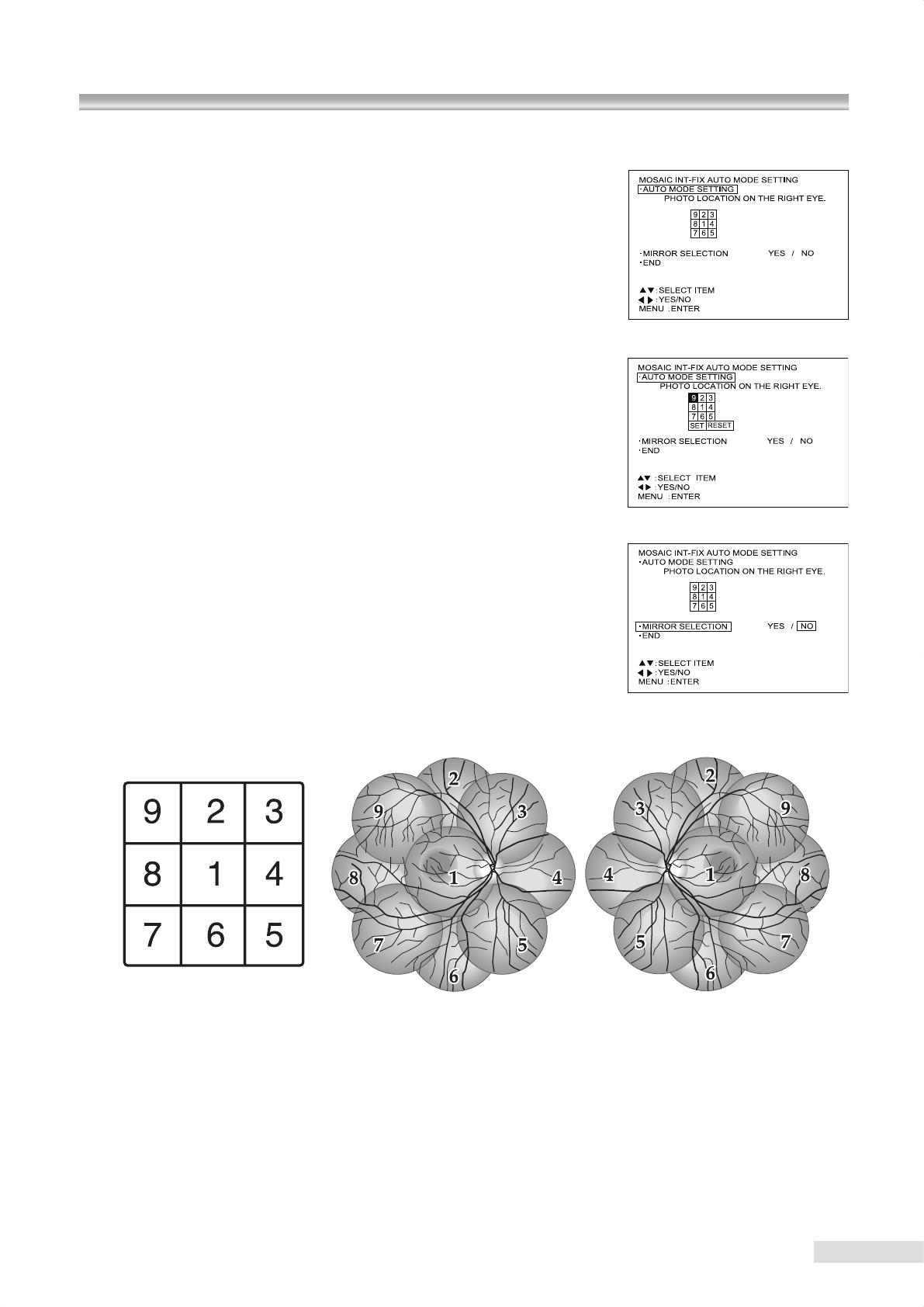
32
9.3.2 Settings of auto mode
Press menu button while “AUTO” is highlighted to access “MOSAIC INT-
FIX AUTO MODE SETTING”. Pressing menu button while “AUTO MODE
SETTING” is highlighted makes one of the numbers shown under “PHOTO
LOCATION ON THE RIGHT EYE” highlighted and allows you to start setting
the photographing order. The current setting appears rst when you access
“AUTO MODE SETTING”.
Use
“
G
,
H
,
F
, and
E
”
keys to move to the number of your choice.
Select and highlight the number corresponding to the photographing part of
the eye in the order you want to photograph and press menu button to set the
illuminating order.
When you terminate setting, highlight “SET” and press menu button.
When you want to restart the setting, highlight “RESET” and press menu
button.
Also you can select the mirror symmetry of illuminating orders for the left and
right eyes. When you want to apply the mirror symmetry, highlight “MIRROR
SELECTION”, select “YES”, and press menu button. When you do not apply
the mirror symmetry, select “NO” and press menu button.
When you select “YES” for the “ MIRROR SELECTION”, illuminating orders are as shown below.
Setting of illuminating orders Right eye Left eye
9.1 Starting menu / 9.2 Objective lens cleaning lamp
9.3 Mosaic internal xation target setting (Switching internal xation target in mosaic mode photography)
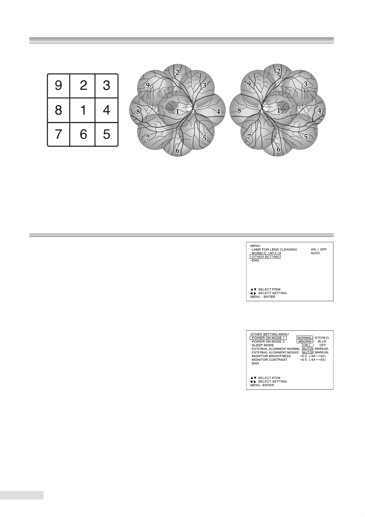
33
When you select “NO” for the “MIRROR SELECTION”, illuminating orders are as shown below.
Setting of illuminating orders Right eye Left eye
Select “SET” and press menu button in “MOSAIC INT-FIX AUTO MODE SETTING” to save the settings and return to
menu item selection.
When the power supply is turned OFF before pressing “SET”, the settings you have made will not be saved.
9.4 Other setting menu
Press menu button while “OTHER SETTING” is highlighted to access the sub
menu screen for other settings of this instrument.
9.4.1 POWER ON MODE 1
This item allows you to select the photography mode when the instrument is
turned ON.
Setting
NORMAL : Normal mode (Factory setting)
STEREO : Stereo mode
How to set
Press “ F ” or “ E ” button to switch the setting while “POWER ON
MODE 1” is selected. Press menu button while the setting of your
choice is highlighted to select the setting and return to menu item
selection.
9 Menu operation
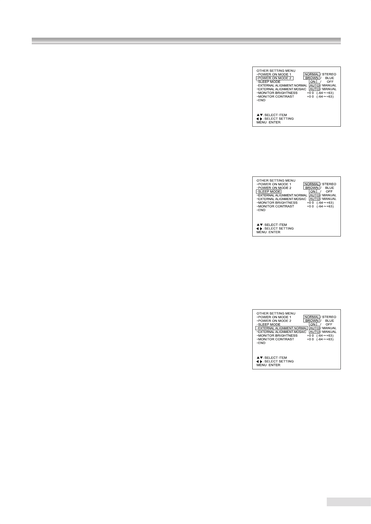
34
9.3 Mosaic internal xation target setting (Switching internal xation target in mosaic mode photography)
9.4 Other setting menu
9.4.2 POWER ON MODE 2
This item allows you to select the state of Blue/Brown selection switch when
turning the instrument is turned ON.
Setting
BROWN : Brown eye (Factory setting)
BLUE : Blue eye
How to set
Press “ F ” or “ E ” button to switch the setting while “POWER ON
MODE 2” is selected. Select “END” and press menu button while the
setting of your choice is highlighted to conrm the setting and return to
menu item selection.
9.4.3 SLEEP MODE
You can select “SLEEP MODE” (power saving mode) as the initial power mode
when the instrument is turned ON. When this instrument is not operated for a
certain period of time (approximately 10 minutes) it goes into “SLEEP MODE”.
In “SLEEP MODE, the LCD” monitor and all lamps of observation illumination
lamps except the chin rest raising and lowering button indicator lamp (the
indicator lamp ashes during “SLEEP MODE”) turn OFF. When you activate
any part of the instrument, it recovers from “SLEEP MODE”.
Setting
ON : SLEEP MODE (Factory setting)
OFF : Normal mode
How to set
Press “ F ” or “ E ” of menu buttons to switch the setting while “SLEEP
MODE” is selected.
9.4.4 EXTERNAL ALIGNMENT : NORMAL
In normal mode, you can set whether or not the display automatically switches
back to anterior segment observation after photography.
Setting
AUTO : The display automatically switches back to anterior
segment.
MANUAL : The display does not automatically switch back to anterior
segment.
How to set
Press “ F ” or “ E ” button to switch the setting while “EXTERNAL
ALIGNMENT : NORMAL” is selected. Select “END” and press menu
button while the setting of your choice is highlighted to select the
setting and return to menu item selection.
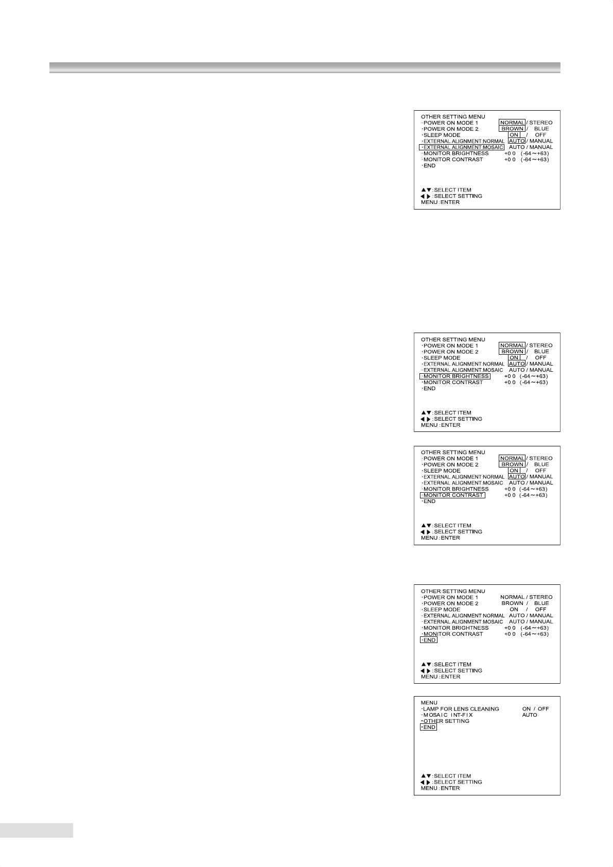
35
9 Menu operation
9.4.5 EXTERNAL ALIGNMENT : MOSAIC
In mosaic mode photography, you can set whether or not the display
automatically switches back to anterior segment observation after
photography.
Setting
AUTO : The display automatically switches back to anterior
segment.
MANUAL : The display does not automatically switch back to anterior
segment.
How to set
Press “ F ” or “ E ” button to switch the setting while “EXTERNAL
ALIGNMENT : MOSAIC” is selected. Select “END” and press menu
button while the setting of your choice is highlighted to select the
setting and return to menu item selection.
9.4.6 MONITOR BRIGHTNESS / CONTRAST
Press menu button while “MONITOR BRIGHTNESS” or “MONITOR
CONTRAST” is selected to display an observation image. Use the image to
set the LCD monitor screen brightness or contrast.
Press “ G ” or “ H ” key to increase or decrease the brightness or contrast.
While looking at the observation image on the LCD monitor, select an
appropriate brightness or contrast and press menu button.
9.4.7 Exiting a menu
To exit menu mode, select “END” in any of the menu screen.
36
This instrument is a precision instrument and daily maintenance and inspection would affect the imaging results. Please
read the following information carefully in order to use this product correctly and safely.
10.1 Daily maintenance
1. What to do after use:
Turn the power switch OFF
Place the lens cap on the objective lens
Place the dust cover over the instrument
2. Check that no dust, debris, nger print, or body uid is found on the objective lens.
3. Determine that the objective lens is clean before you start using the instrument the rst time each day.
Dirty objective lens is readily identied under the objective lens cleaning lamp (see “9.2 objective lens cleaning
lamp”).
When the objective lens is dirty, follow the steps described in “10.4 Cleaning the objective lens” to clean it.
4. Condensation may occur on the objective lens when the instrument is moved into an environment where there is
temperature difference. When condensation occurs, wait until it disappears before use.
5. When condensation occurs repeatedly, lenses may get moldy.
When such a case has occurred to you, contact Kowa or your Kowa dealer.
6. Disconnect the power supply cable when the instrument is not used for an extended period of time.
10.2 Daily inspection (by users)
Inspect this instrument in accordance with “KOWA nonmyd WX daily inspection table”.
When an anomaly found during the inspection may not be solved using any of the maintenance methods described in
this instruction manual, contact Kowa or your Kowa dealer.
KOWA nonmyd WX daily inspection table
Inspection Procedure Acceptability criteria
Power cable Visually verify that the cable has no aw
or damage. No aw or damage should be found.
Objective lens See
“10.4 Cleaning the objective lens”.
No dust, debris, fingerprint, teardrop
must be found.
Exterior Visually verify that the exterior has no
aw, crack, deformation or rust.
Exterior components must have no
aw, crack, deformation or rust.
Plates and labels
Visually verify that the ID plate and la-
bels is readily readable and not contami-
nated.
Rating plates and labels must be read-
able.
Shutter button and ash lamp
Make the instrument ready for photogra-
phy. Hold your hand in front of the objec-
tive lens. Push the shutter button and
visually verify that the ash light emitted
through the objective lens illuminates the
hand (do not look into the objective lens).
Pressing the shutter button must acti-
vate the ash lamp to emit the light.
10 Maintenance and inspection
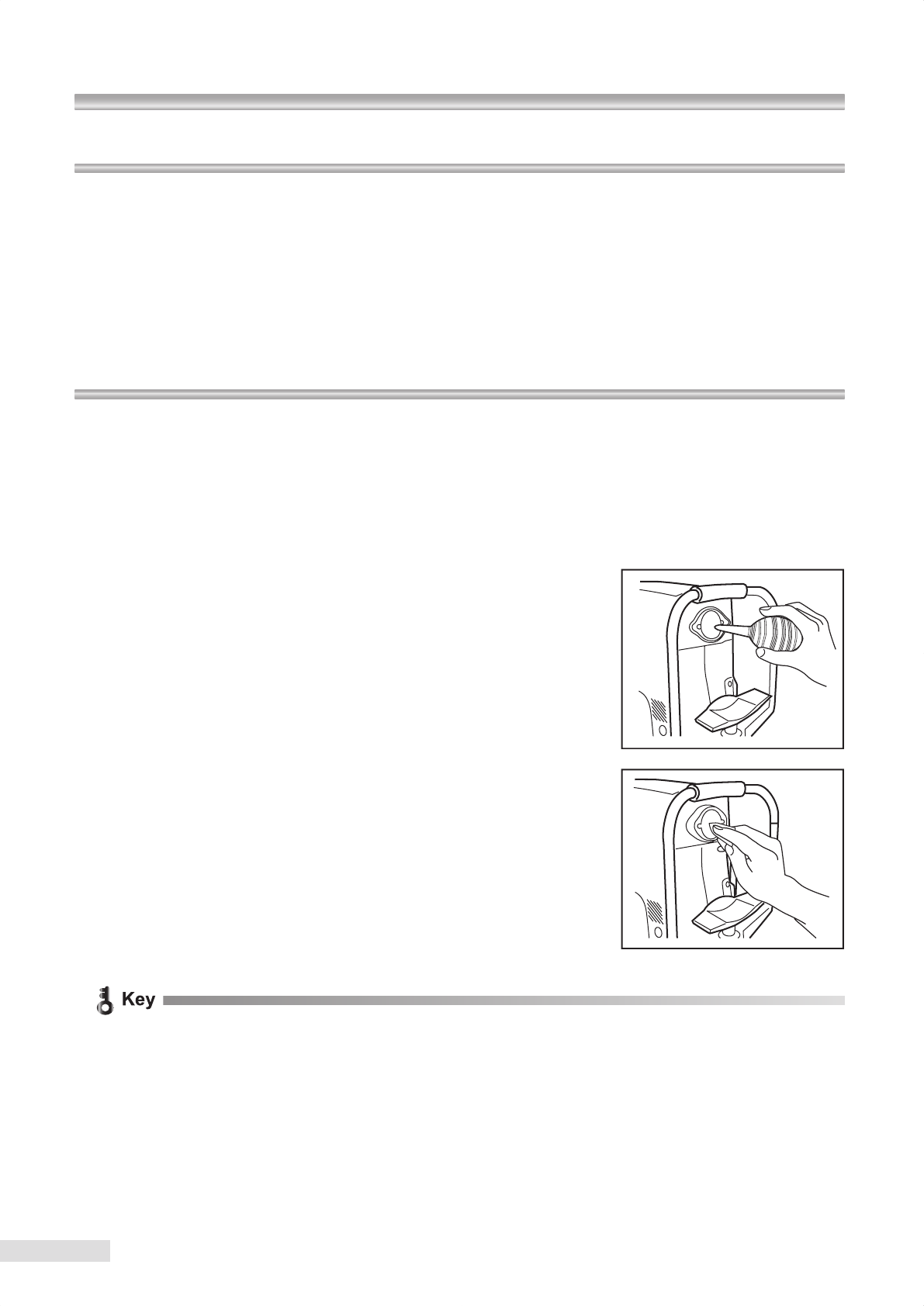
37
10.3 Regular inspection (by manufacturer)
In order to use this instrument safely over its useful life, we recommend you to have it inspected annually. Contact Kowa
or your Kowa dealer for details and cost of inspections.
1. External components and their installation
2. Optical components
3. Operations and functions of components
4. Photograph quality inspection using standard model eye (0D)
5. Photography light intensity
10.4 Cleaning the objective lens
You can not obtain a good image if the objective lens is contaminated with ngerprints, etc. Clean the lens as described
below:
1 Turn ON power switch.
2 In order to identify soils on the objective lens clearly, reduce room’s luminance, and turn ON the objective lens
cleaning lamp.
(Refer to “ 9.2 Objective lens cleaning lamp” for details of how to turn ON the objective lens cleaning lamp.)
3 Using high-pressure air, blow off debris or dust.
4 When the air does not clean the objective lens, moisten soft cloth or
cleaning paper with cleaning solution made from ethyl alcohol and ether
(1:1) and clean the lens starting from its center in a circular motion.
x Tips for lens cleaning
Do not reuse soft cloth or cleaning paper but use new soft cloth or cleaning paper moistened with cleaning solu-
tion to obtain the best results.
k Cleaning the lens without removing soils or applying a strong force when wiping may scratch the lens surface.
k Do not use chamois leather, silicon cloth, or eyeglass cleaner paper, etc.
k Carefully store and handle the ammable and combustible cleaning solution.
5 If any soil is left out after cleaning with the cleaning solution, gently wipe off the soiled area with a cotton swab soaked
with a little amount of water. After this cleaning step, wipe the lens using the cleaning solution described above.
Should you have stubborn soil that cannot be removed by the steps above, contact Kowa or your Kowa dealer.
6 Turn OFF the objective lens cleaning lamp after the lens cleaning is completed.
10 Maintenance and inspection
38
10.3 Regular inspection (by manufacturer) / 10.4 Cleaning the objective lens
10.5 Disinfection / 10.6 Outer cleaning / 10.7 Replacing ash lamp
10.5 Disinfection
Wipe the forehead rest with rubbing alcohol as soon as a patient completes the examination. Also wipe the chin rest with
rubbing alcohol when no chin rest paper is used.
10.6 Outer cleaning
Caution
Prohibitory
Do not wipe the outer surface of the instrument with solvents
such as benzene, alcohol, thinner, ether. Such substances may
cause the surface to be discolored or deteriorated.
x Wipe the outer surface with soft cloth, from which water (used to moisten the cloth) was rmly squeezed off.
x Lightly wipe the LCD monitor screen cover with soft cloth such as gauze because it is easily damaged.
Wipe off the obstinate dirt with soft cloth, from which water or lukewarm water used to dilute a small amount of
neutral detergent was squeezed off.
10.7 Replacing ash lamp
Warning
Unplug Warning
High-Voltage
Wh e n r e p l a c in g t h e f la s h lam p , m ak e
sure the instrument is turned OFF and un-
plugged from the power outlet.
Otherwise, there may occur electrical shock.
Warning
Unplug Warning
High-Voltage
This instrument is equipped with a storage
capacitor for photography light. Replacing the
flash lamp while this capacitor is still not yet
fully discharged causes a danger of an electric
shock. Check that the discharge indicator LED
is turned OFF before replacing the ash lamp.
Caution
Prohibitory Caution
High-temperature
Do not replace the flash lamp immediately af-
ter turning the instrument OFF. You could be
burned by a lamp heated to a high temperature.
Allow 10 minutes to cool it down before re-
placing.
Caution
Prohibitory
Do not touch the ash lamp bulb with your bare hands. Other-
wise, the lamp may reduce the light intensity and longevity.
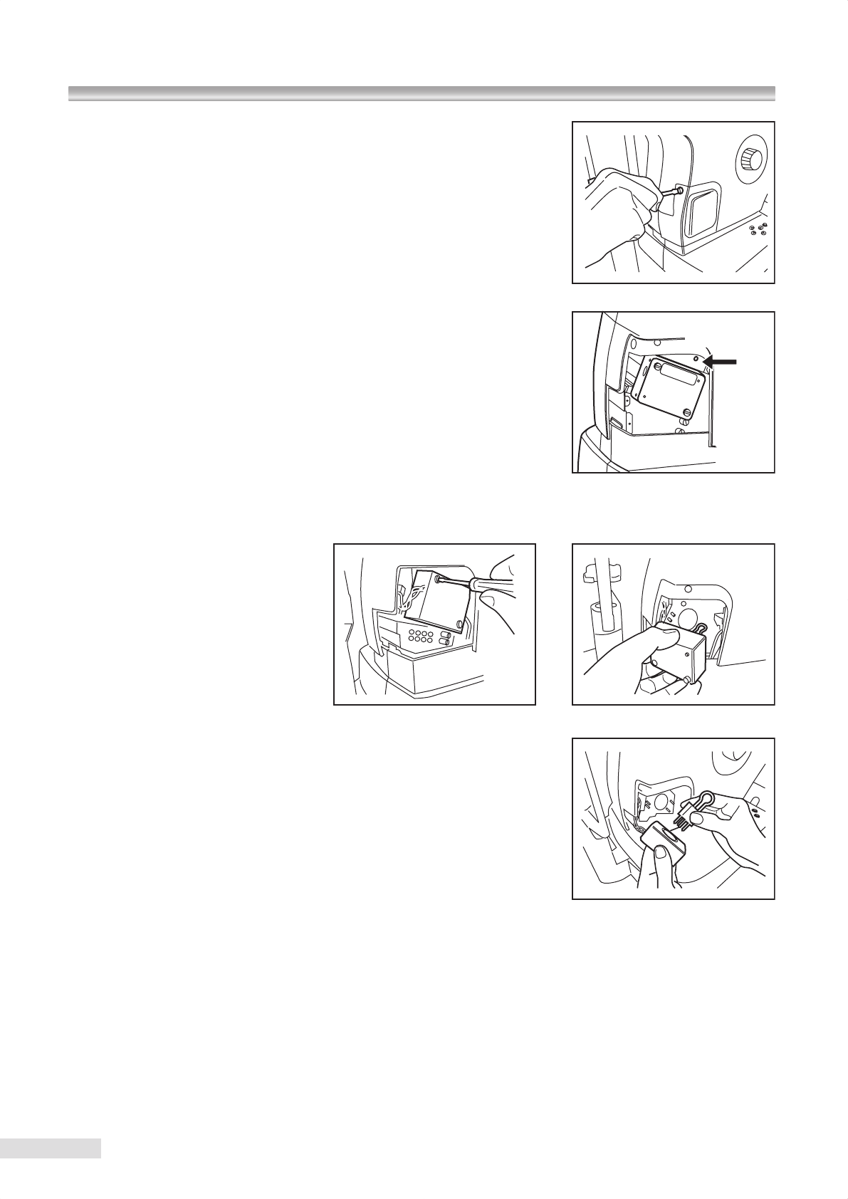
Discharge
indicator
LED
39
1 Rotate control lever to move optical head to the uppermost location.
2 Turn OFF the power switch and unplugged from the power outlet.
3 Loosen lamp cover screws with a coin or a screwdriver and then remove
lamp cover.
Make sure that the ash lamp has been cooled down before proceeding to
the next step.
4 Check that the discharge indicator LED shown in the gure is completely
turned OFF.
It normally turns OFF completely within three minutes after the instrument
is turned OFF. If it does not turn OFF even after above period of time,
contact Kowa or your Kowa dealer as it may carry a risk of failure.
In such a case, never touch the instrument.
k Discharge indicator LED illuminates only when it discharges after the
instrument is turned OFF.
5 After the discharge indicator LED is turned OFF and the ash lamp is fully cooled down (about 10 minutes after the
power is turned OFF), unscrew two screws by a screwdriver and remove the ash lamp socket.
6 Hold the lamp and its socket in your hand, remove the ash lamp, and
install a new lamp in the socket.
k When replacing the ash lamp, pull straight out and push straight in the
bulb towards the direction of electrode pin. Do not twist the ash lamp
when tting or removing it.
k Fully insert the ash lamp to the end of the socket.
k Do not touch the ash lamp bulb.
7 Tighten two screws of the ash lamp socket with a driver. Pay attention not to pinch the cables around the instrument
when installing the ash lamp socket.
8 Place lamp cover and tighten lamp cover screws with a coin or a driver.
k When installing the lamp cover, make sure that the cable of the illumination lamp socket is snugly housed within
the external sheath.
9 Connect the power supply cable plug to the power outlet and turn ON the power switch.
0 Turn ON the instrument and perform test photography.
10 Maintenance and inspection
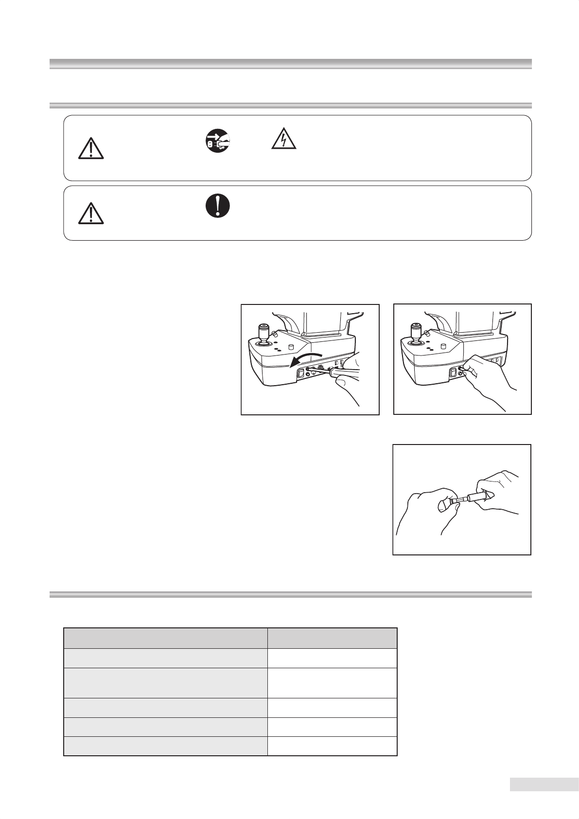
40
10.7 Replacing ash lamp / 10.8 Fuse replacement /
10.9 Relling and replacing consumables
10.8 Fuse replacement
Warning
Unplug Warning
High-Voltage
When replacing the fuse, make sure the instru-
ment is turned OFF and unplugged from the
power outlet.
If the fuse holder cover is removed with the in-
strument unplugged, there may occur electrical
shock.
Warning
Obligatory
Use a designated fuse only.
Otherwise, the instrument may malfunction or a re may break
out.
1 Turn OFF the power switch and pull the plug from the power outlet.
2 Make sure that the instrument is turned OFF and wait for discharge at least 5 minutes for safety.
3 Press down the fuse holder with a screwdriver and turn the fuse holder to the direction of the arrow (counterclockwise)
for removal.
4 Pull the old fuse and replace it with a new one. Make sure that the fuse
type and rating are correct.
5 Press down the fuse holder with a screwdriver and turn the fuse holder to
the opposite direction of the arrow (clockwise) and install it in place.
6 Connect the power cable plug to an power outlet.
10.9 Relling and replacing consumables
Order spare parts by purchase order numbers listed below to Kowa or your Kowa dealer.
Part name Purchase order number
Flash lamp K9L39FU
Fuses 21802.5M
(T2.5AL250V)
Chin rest paper K9L-TB45#102
Chin rest paper retaining pin K9L-TB45#101
Dust cover AFT2#179
41
Shooting mode Normal / SP / Stereo (electrically switched)
Stereoscopic photography method Simultaneous stereo photography
Stereo photography parallax 7.4° (at the 0 diopter eye)
Field angle
Normal mode : 45°
SP mode : 45°
Stereo mode : 34° (20° horizontal and 27° vertical directions)
*
Some eyes may cause a are around their circumference.
Tolerance of pixel pitch on fundus
(ISO 10940)
Normal image : S*( 9 μm ± 7 %)
L*(4.5 μm ± 7 %)
Stereo image : S*(5.5 μm ± 7 %)
L*(2.7 μm ± 7 %)
Working distance 30 mm
Minimum pupil size
Normal mode : 4.0 mm
SP mode : 3.5 mm
Stereo mode : 4.0 mm
Compensation range of
examined eye
Without compensation : −12 m-1(D) to +13 m-1(D)
Compensation + : +10 m-1(D) to +35 m-1(D)
Compensation − : −32 m-1(D) to −10 m-1(D)
Focusing Split luminous bars coincidence
Working distance adjustment 2 luminous dots indication type
Camera Specic Nikon digital SLR camera
Monitor 5.7-inch LCD monitor
Light source Observation : Near-infrared LED
Photography : Xenon ash lamp
Internal xation target Central, Disc, Macula,mosaic 8 positions
Optical head base adjustment range
Movable 40mm forward/backward
Movable 98mm leftward/rightward
Movable 27mm vertically (electric)
Chin rest adjustment range Movable 55mm (electric)
Interfaces
Image output : USB (B type)
Imaging conditions output : USB (mini-B type )
Numerical keypad input : USB (A type)
Power supplies Input : AC100-240V, 50/60Hz
Power consumption : 150VA
Dimensions 310(W)x504(D)x548(H)mm
Weight 21kg / 46lbs (excluding the attached digital SLR camera)
*S/L : Image size set on the digital camera
Compliance standard
• EN 60601-1:1990+A1:1993+A2:1995
• EN 60601-1-2:2001+A1:2006
Classication of equipment based on EN 60601-1
• According to the type of protection against electric shock
(Class device)
• According to the degree of protection against electric shock
(Type B applied part)
• According to the type of protection against ingress of water as detailed in the current edition of IEC60529.
(IPX0)
• According to the degree of safety of application in the presence of a ammable anaesthetic mixture with air or with
oxygen or nitrous oxide.
(Equipment not suitable for use in the presence of a flammable anesthetic mixture with air or with
oxygen or nitrous oxide)
• According to the mode of operation.
(continuous operation)
Complied EC Directive
Medical Device Detective 93/42/EEC :
WEEE Directive 2002/96/EC
11 Specications
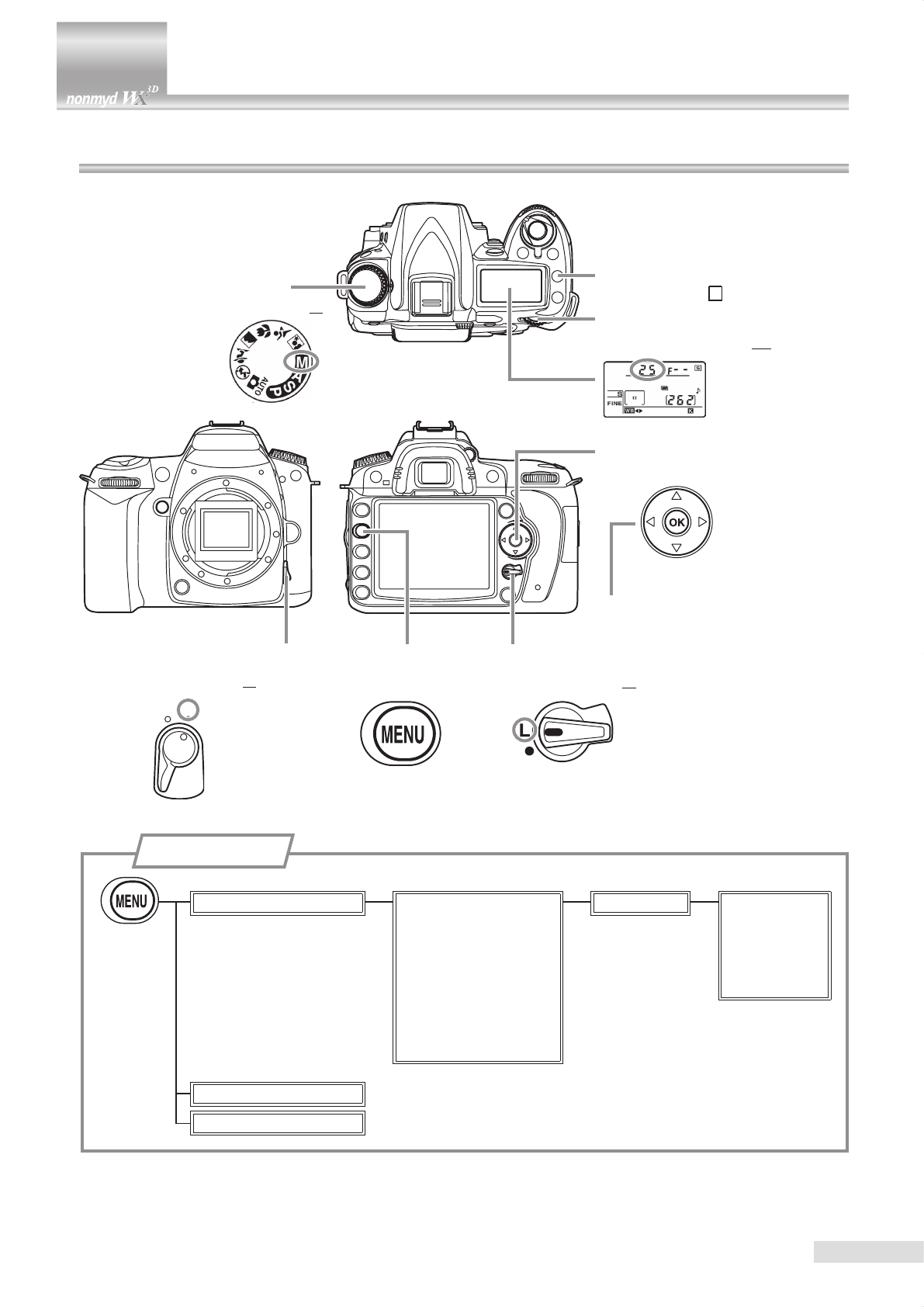
AF
M
42
12 Technical information
12.1 Description of digital camera
Focus-mode selector
Set the mode to “M”
Focus selector lock
Set the selector to “L”
Mode dial
Set the mode to “M”
Multi selector
Move up
Move to the lower
hierarchy, Conrm
Move down
Move to the upper
hierarchy, Chancel
Menu button
SHOOTING MENU Set picture control
Image quality
Image size
White balance
ISO sensitivity settings
Color space
Long exp. NR
High ISO NR
Standard Sharpening
Contrast
Brightness
Saturation
Hue
CUSTOM SETTING MENU
SETUP MENU
Menu hierarchy
Main command dial
Set the shutter speed to 1/25.
Release mode button
Set the mode to “ S ”
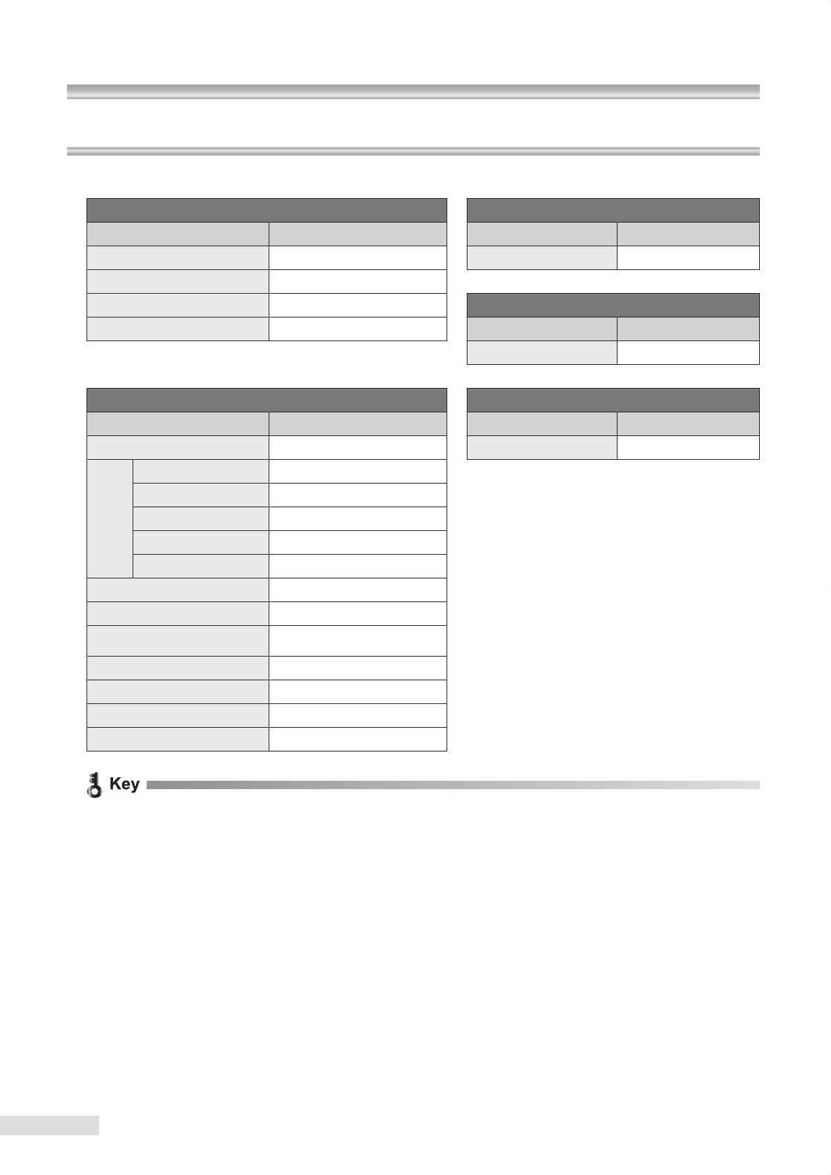
43
12.2 digital camera setting
Ensure that the digital camera settings are correctly congured.
Dial setting Custom menu
Menu items Setting Menu items Setting
Mode dial M No memory card? LOCK
Focus-mode selector M
Focus selector lock LSet-up menu
Shutter speed *51/25 Menu items Setting
k5 Use Main command dial to set the shutter speed. Language English
Photography menu Release mode
Menu items Setting Menu items Setting
Set picture control Standard Release mode Single frame
Sharpening
+4
Contrast 0
Brightness 0
Saturation −1 k6
You may change photo quality mode an
d Im-
age size at your discretion.
Image
quality
: FINE, NORMAL, BASIC
Image size : L, M, S
Hue +2
Image quality*6FINE
Image size*6S (2144×1424)
White balance color temperature setting
5560(A4,M1)
ISO sensitivity settings 400
Color space sRGB
Long exp. NR
OFF
High ISO NR
OFF
x Do not turn OFF the digital camera when communication is ongoing between the digital camera and the PC.
x The items not shown above may use their default settings.
12 Technical Information
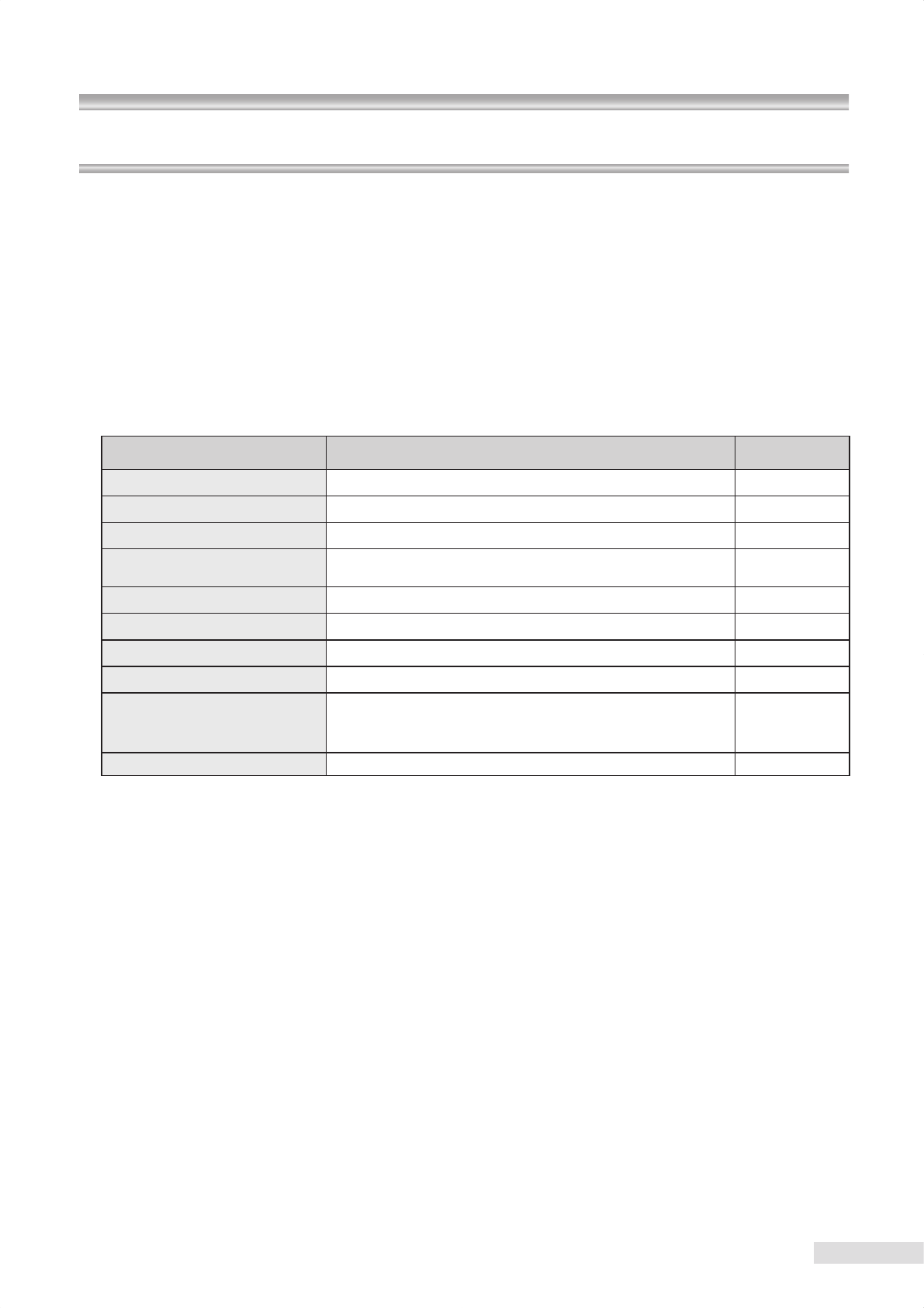
44
12.2 digital camera setting / 12.3 Imaging condition output
12.3 Imaging conditions output
This instrument outputs the imaging conditions from Imaging condition output terminal. If you want to read the imaging
conditions using application software other than that provided with the instrument, refer to the specications below:
For this purpose, you need to install FTDI “Direct (D2XX) driver Ver 2.04.06 or later” into your PC to which this instru-
ment is connected.
Communication related specications
Baud rate : 38400
Data length : 8 bit
Parity : even
Stop bit : 1 bit
Flow control : none
Output data
Output item Description Example
Model name Fixed value K9L57
Instrument number 10-digit number 16174]]]]]
Photography mode NORMAL/SP/STEREO STEREO
Light intensity selector knob
position -2/-1/0/+1/+2 0
Blue or brown eye BLUE/BROWN BLUE
Diopter compensation 0/D+/D- 0
Left or right eye L/R R
Fixation target 1 to 7/EXT 1 to 7
Internal xation target illuminat-
ing position
C (Posterior), N (optic disc), M (Macula), U (Up)
UR (Upper right), UL (Upper left), R (Right), L (Left), D (Down),
LR (Lower right), LL (Lower left)
C
Observation screen ANTE/FUNDS FUNDS
k A linefeed code is inserted every output of an item.
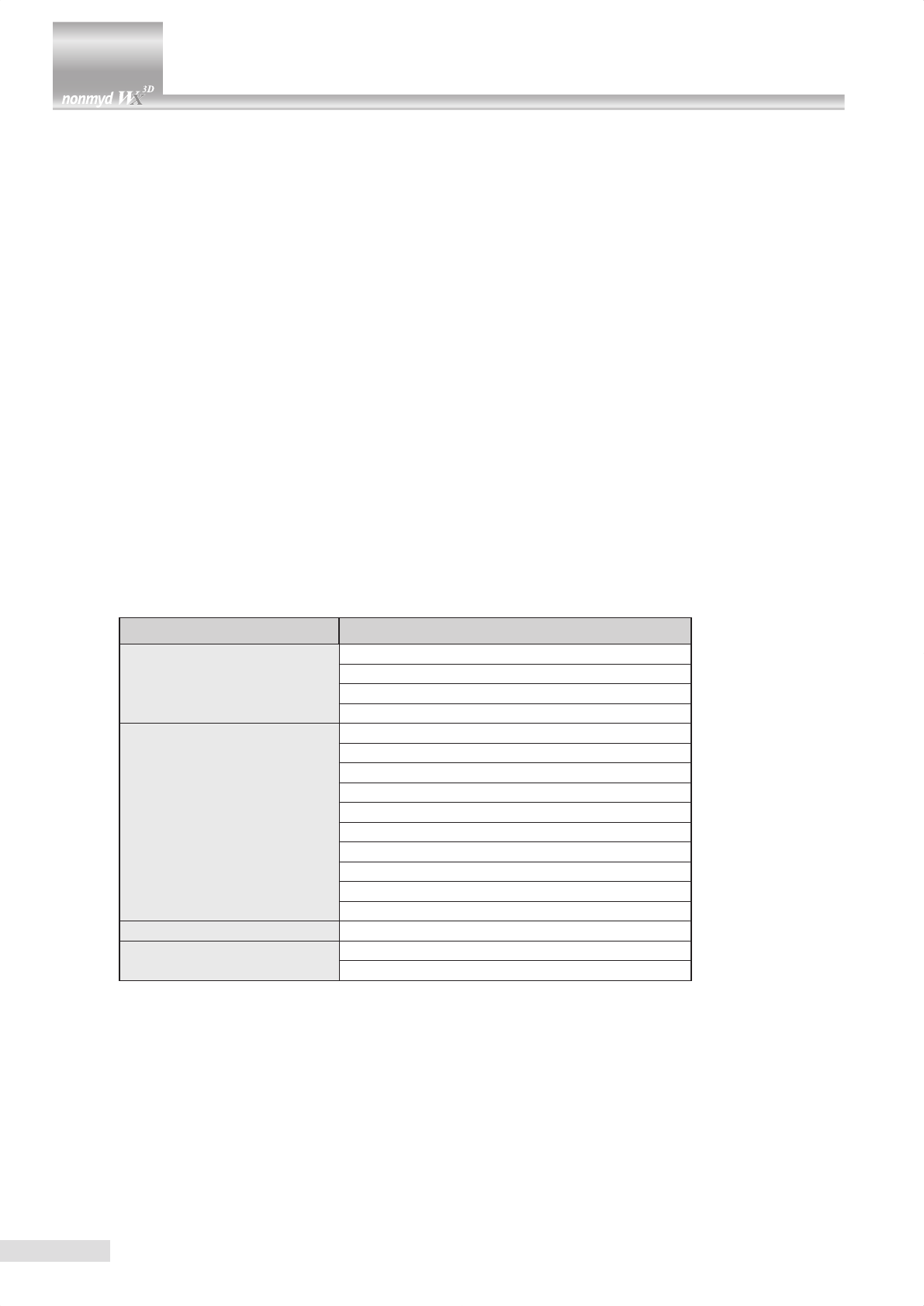
45
13
Electromagnetic compatibility (IEC60601-1-2)
This instrument is a medical electrical instrument. Medical electrical instruments are requireed special attention to the
electromagnetic compatibility (EMC). The following section describes the EMC and precautions regarding this instrument.
When installing or using this instrument, read the description carefully and follow the directions described.
(The EMC of this instrument was tested based on IEC60601-1-2.)
1. Please note that portable- or mobile-type radio frequency communication devices (RF communications instrument)
may adversely affect this instrument resulting in malfunctioning.
2. The electromagnetic compatibility (EMC) of this instrument was tested with the options and accessories shown below.
Since using an option or accessory other than those specied may cause malfunctioning of this instrument due to
interferences of other device or cause malfunctioning of other device, use only the options or accessories specied
for this instrument.
● 100V power supply cable : KP300VCTF3X1.25SQKS16A, 2.5 m
● 120V power supply cable : KP320SJT18X3KS31, 2.5 m
● 230V power supply cable : KP-4819Y KS-31A, 2.5 m
● PC : CE Marking, VCCI, and FCC approved PC
● USB cable (Type A-B) : 3 m
● USB cable (Type A-Mini- B) : 3 m
● Numerical keypad
● External xation target (K9L-LE57)
3. This instrument is not designed such that it can be used adjacent to other instrument or placing one on top of another.
Therefore, do not apply such use. Nevertheless, if such use is inevitable, it is necessary to monitor constantly if the
instrument is functioning normally after such use has been adopted.
4. Accessories and options used with this instrument are tested for EMC when combined with instrument below. Since
using with an instrument other than that specied may cause malfunctioning of this instrument due to interferences of
other devices or cause malfunctioning of other devices, do not use any instrument other than specied below.
Option 1: CE Marking, VCCI, and FCC approved PC
5. We specied the functions listed in the table blow as the basic performance of this instrument to determine EMC of
this instrument.
Functions Essential performance
Light-emitting functions
Light-emitting function
Illumination light intensity setting and switching
Illumination light intensity settings
Charge function
Instrument operation functions
Optical head vertical movement
Chin rest vertical movement
Anterior segment/retinal switching
Normal mode switching
SP mode switching
Stereo mode switching
Anterior segment illumination
Retinal observation light intensity adjustment
W.D. ON/OFF
F.D. ON/OFF
Photography functions Image signal output
LCD monitor display functions LCD monitor screen display (OSD)
LCD monitor screen display (through image)
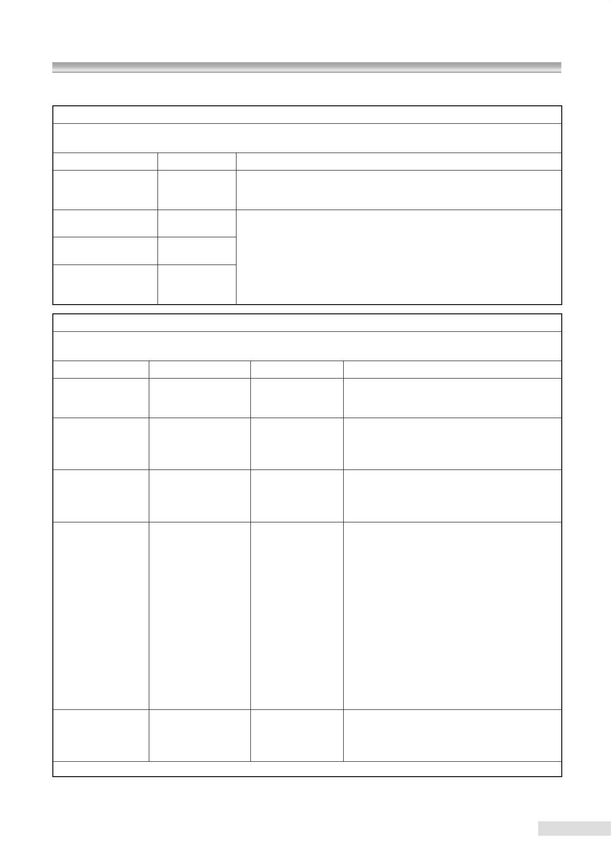
46
13 Electromagnetic compatibility (IEC60601-1-2)
[Compliance verication and guidance]
Guidance and manufacturer’s declaration - electromagnetic emissions
KOWA nonmyd WX is intended for use in the electromagnetic environment specied below.
The customer or the user of KOWA nonmyd WX should assure that it is used in such an environment.
Emissions test Compliance Electromagnetic environment - guidance
RF emissions
CISPR 11
Group 1
KOWA nonmyd WX uses RF energy only for its internal function. There-
fore, its RF emissions are very low and are not likely to cause any interfer-
ence in nearby electronic instrument.
RF emissions
CISPR 11 Class B
KOWA nonmyd WX is acceptable in all types of facilities without any limita-
tion to the electrical supply network connected to KOWA nonmyd WX.
Harmonic emissions
IEC 61000-3-2 Class B
Voltage uctuations/
icker emissions
IEC 61000-3-3
Complies
Guidance and manufacturer’s declaration - electromagnetic immunity
KOWA nonmyd WX is intended for use in the electromagnetic environment specied below.
The customer or the user of tKOWA nonmyd WX should assure that it is used in such an environment.
Immunity test IEC60601 test level Compliance level Electromagnetic environment - guidance
Electrostatic
discharge(ESD)
IEC61000-4-2
±6kV contact
±8kV air
±6kV contact
±8kV air
Floors should be wood, concrete or ceramic tile.
If oors are covered with synthetic material, the
relative humidity should be at least 30%.
Electrical fast
transient/burst
IEC61000-4-4
±2kV for power
supply lines
±1kV for
input/output lines
±2kV for power
supply lines
±1kV for
input/output lines
Mains power quality should be that of a typical
commercial or hospital environment.
Surge
IEC61000-4-5
±1kV
differential mode
±2kV
common mode
±1kV
differential mode
±2kV
common mode
Mains power quality should be that of a typical
commercial or hospital environment.
Voltage dips, short
interruptions and
voltage variations
on power supply
input lines
IEC61000-4-11
<5% UT
(>95% dip in UT)
for 0.5 cycle
40% UT
(60% dip in UT)
for 5 cycles
70% UT
(30% dip in UT)
for 25 cycles
<5% UT
(>95% dip in UT)
for 5 sec
<5% UT
(>95% dip in UT)
for 0.5 cycle
40% UT
(60% dip in UT)
for 5 cycle
70% UT
(30% dip in UT)
for 25 cycle
<5% UT
(>95% dip in UT)
for 5 sec
Mains power quality should be that of a typical
commercial or hospital environment. If the user
of KOWA nonmyd WX requires continued opera-
tion during power mains interruptions, it is rec-
ommended that KOWA nonmyd WX be powered
from an uninterruptible power supply.
Power frequency
(50/60Hz)
magnetic eld
IEC61000-4-8
3 A/m 3 A/m
Power frequency magnetic fields should be at
levels characteristic of a typical location in a
typical commercial or hospital environment.
NOTE UT is the a.c. mains voltage prior to application of the test level.
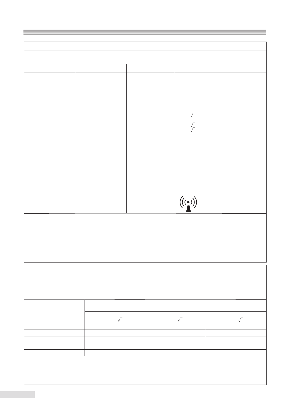
47
13 Electromagnetic compatibility (IEC60601-1-2)
Guidance and manufacturer’s declaration - electromagnetic immunity
KOWA nonmyd WX is intended for use in the electromagnetic environment specied below.
The customer or the user of KOWA nonmyd WX should assure that it is used in such an environment.
Immunity test IEC 60601 test level Compliance level Electromagnetic environment– guidance
Conducted RF
IEC 61000-4-6
Radiated RF
IEC 61000-4-3
3 Vrms
150 kHz to 80 MHz
3 V/m
80 MHz to 2.5 GHz
3 V
3 V/m
Portable and mobile RF communications instru-
ment should be used no closer to any part of
KOWA nonmyd WX, including cables, than the
recommended separation distance calculated
from the equation applicable to the frequency
of the transmitter.
Recommended separation distance
d=1.2 P
d=1.2 P 80 MHz to 800 MHz
d=2.3 P 800 MHz to 2.5 GHz
where P is the maximum output power rating
of the transmitter in watts (W) according to the
transmitter manufacturer and d is the recom-
mended separation distance in metres (m).
Field strengths from xed RF transmitters, as
determined by an electromagnetic site surveya,
should be less than the compliance level in
each frequency rangeb.
Interference may occur in the vicinity of instru-
ment marked with the following symbol:
Recommended separation distances between
portable and mobile RF communications instrument and KOWA nonmyd WX
KOWA nonmyd WX is intended for use in an electromagnetic environment in which radiated RF disturbances are controlled. The cus-
tomer or the user of KOWA nonmyd WX can help prevent electromagnetic interference by maintaining a minimum distance between
portable and mobile RF communications instrument (transmitters) and KOWA nonmyd WX as recommended below, according to the
maximum output power of the communications instrument.
Rated maximum output
power of transmitter
W
Separation distance according to frequency of transmitter
m
150 kHz to 80 MHz
d=1.2 P
80 MHz to 800 MHz
d=1.2 P
800 MHz to 2.5 GHz
d=2.3
NOTE1 At80MHzand800MHz,thehigherfrequencyrangeapplies.
NOTE2 Theseguidelinesmaynotapplyinallsituations.Electromagneticpropagationisaffectedbyabsorptionandreectionfrom
structures, objects and people.
a Field strengths from xed transmitters, such as base stations for radio (cellular/cordless) telephones and land mobile radios,
amateur radio, AM and FM radio broadcast and TV broadcast cannot be predicted theoretically with accuracy. To assess the
electromagneticenvironmentduetoxedRFtransmitters,anelectromagneticsitesurveyshouldbeconsidered.Ifthemeasured
eldstrengthin the locationinwhichtheKOWA nonmyd WX is used exceeds the applicable RF compliance level above, the
KOWA nonmyd WX should be observed to verify normal operation. If abnormal performance is observed, additional measures
maybenecessary,suchasreconguringorrelocatingtheKOWAnonmydWX
b Overthefrequencyrange150kHzto80MHz,eldstrengthsshouldbelessthan3V/m.
P
0.01 0.12 0.12 0.23
0.1 0.37 0.37 0.74
1 1.2 1.2 2.3
10 3.7 3.7 7.4
100 12 12 23
For transmitters rated at a maximum output power not listed above, the recommended separation distance d in metres (m) can
beestimatedusing theequationapplicabletothe frequency ofthetransmitter,wherePisthemaximum output powerratingofthe
transmitter in watts (W) according to the transmitter manufacturer.
NOTE1 80MHzand800MHz,theseparationdistanceforthehigherfrequencyrangeapplies.
NOTE2 Theseguidelinesmaynotapplyinallsituations.Electromagneticpropagationisaffectedbyabsorptionandreectionfrom
structures, objects and people.
For EU market.




© 2010 Kowa Company, Ltd. All rights reserved.
K9L57 V1.0 E 100507
Printed in Japan
Immermannstrasse 43B
40210 Duesseldorf, F.R. Germany
Phone: 49(211) 1793540
Facsimile: 49(211) 161952
Hamamatsu Factory
3-1, Shinmiyakoda 1-chome, Kita-ku, Hamamatsu city, Shizuoka Pref., 431-2103 Japan
4-14, Nihonbashi-honcho 3-chome, Chuo-ku, Tokyo 103-8433 Japan
Phone: 81(3) 3279-7639
Facsimile: 81(3) 3279-7541
(World Sales Headquarters)
