Kpnetworks KPWL0300 Wireless Lan Access Point User Manual USER S MANUAL
Kpnetworks Ltd. Wireless Lan Access Point USER S MANUAL
UserManual.wiki
>
Kpnetworks
>
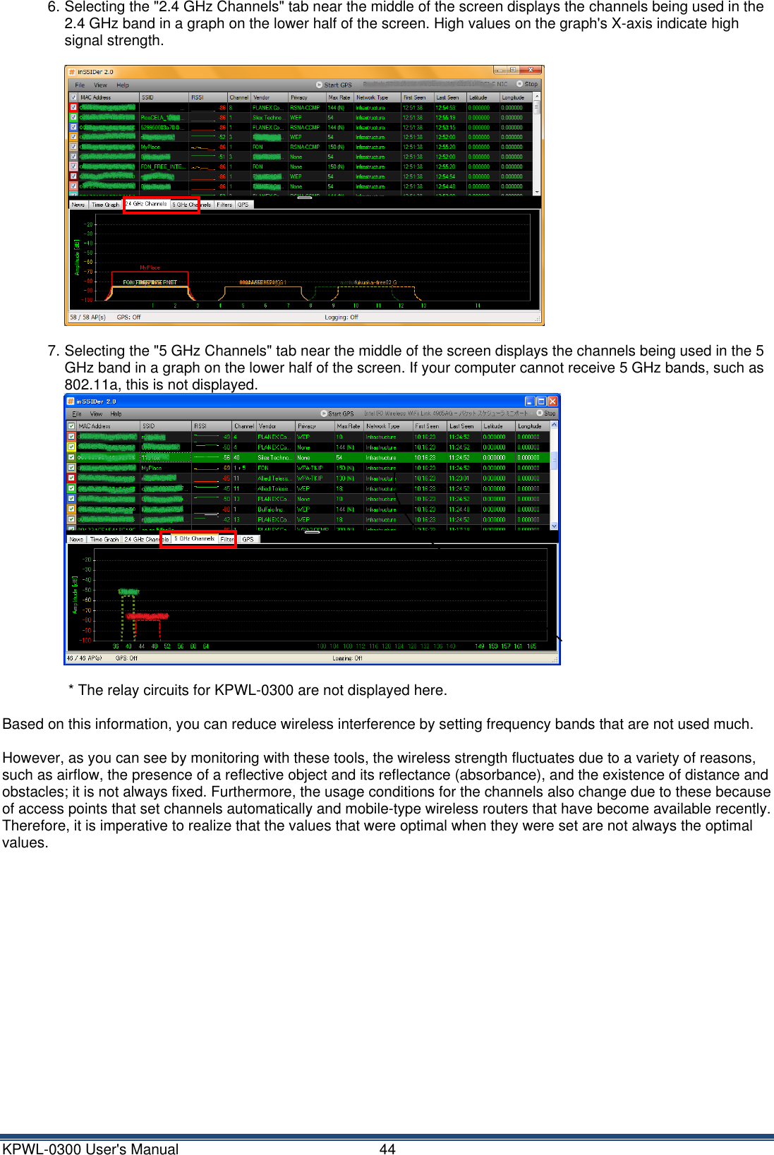
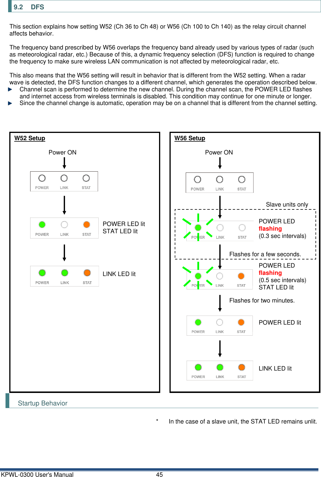
KPWL0300 User Manual
User Manual
Navigation menu
Upload a User Manual
Namespaces
Wiki Guide
HTML
PDF
Info
Views
User Manual
Discussion / Help
Navigation
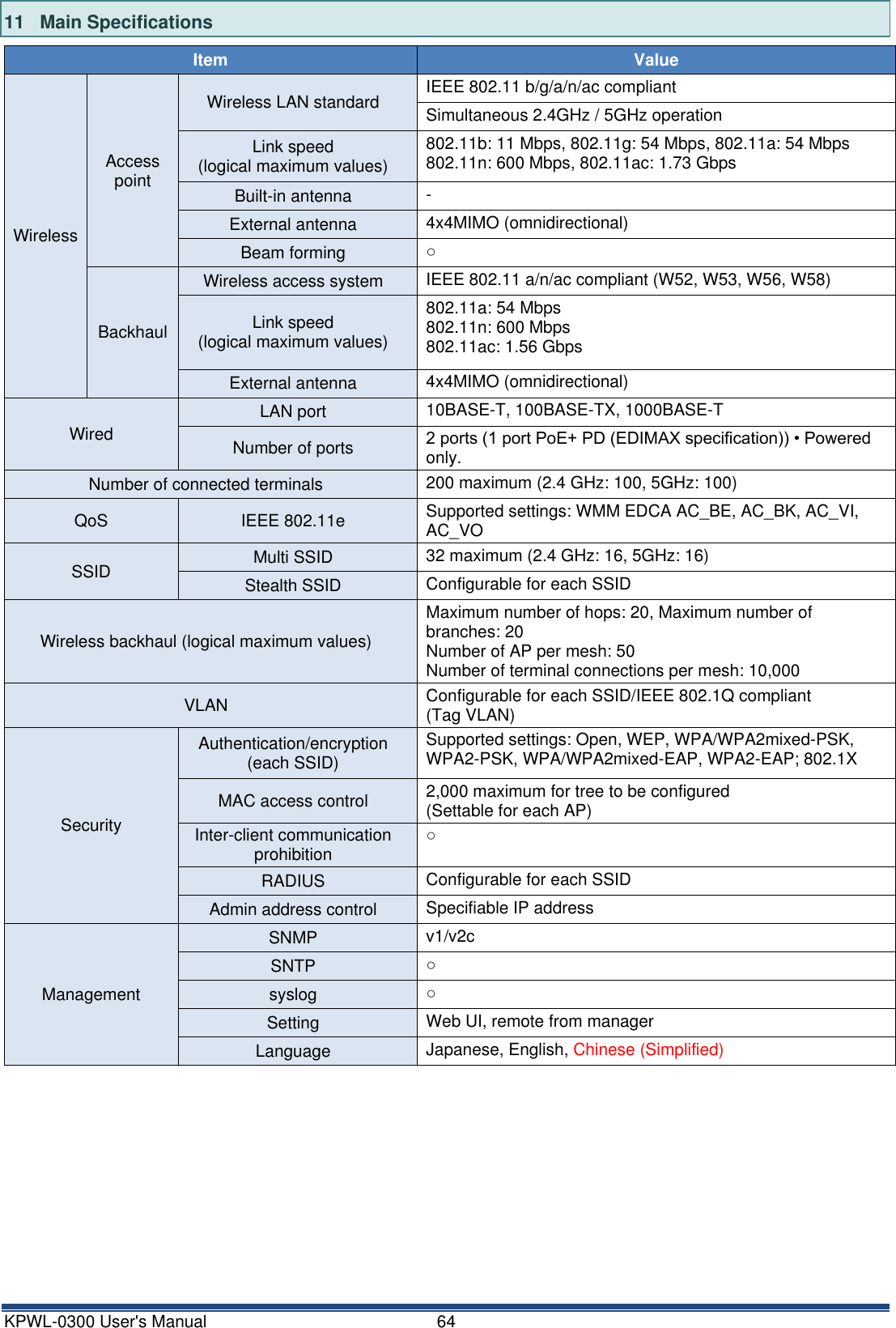
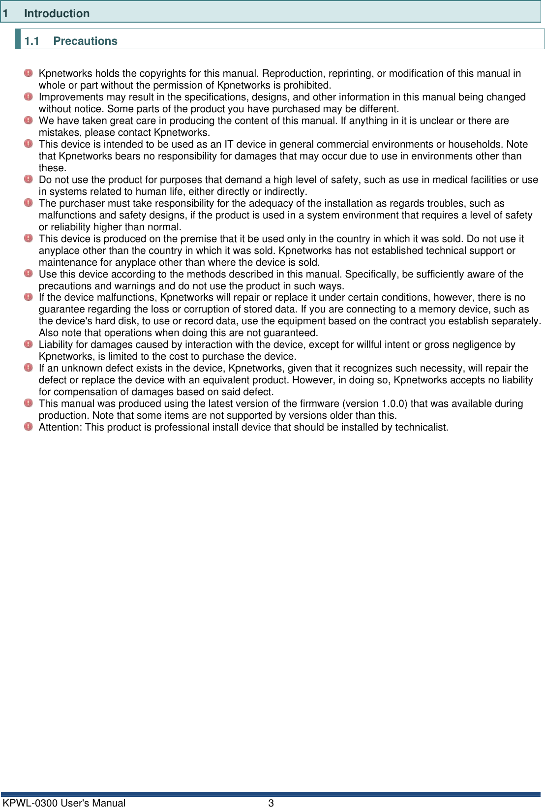
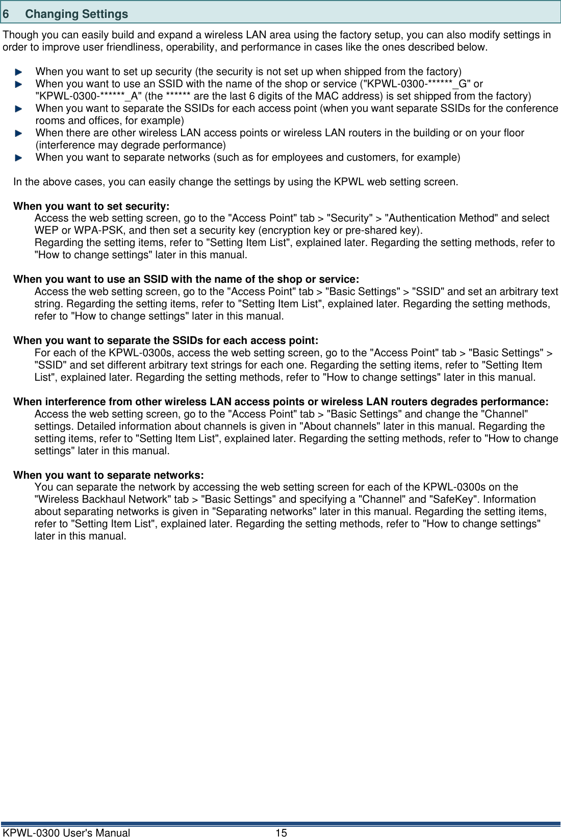
![KPWL-0300 Kpnetworks Ltd. [USER'S MANUAL] VERSION 1.0 (LATEST VERSION 2016/1/13) This manual is a collection of the information and knowledge necessary to install the KPWL-0300 Wireless Access Point from Kpnetworks, which allows you to "Create a Wireless LAN area by just setting it down". With this manual you can do a basic or custom installation of the KPWL-0300 without any further specialized knowledge of wireless networks.](https://usermanual.wiki/Kpnetworks/KPWL0300/User-Guide-3291086-Page-1.png)
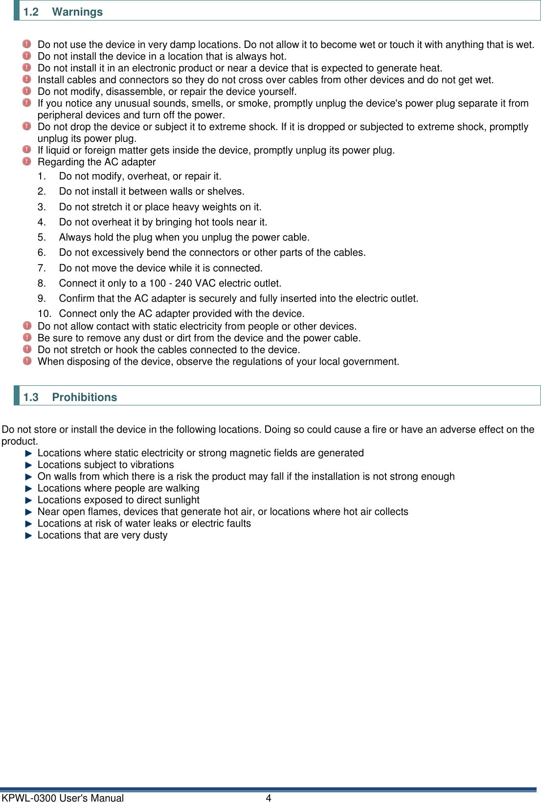
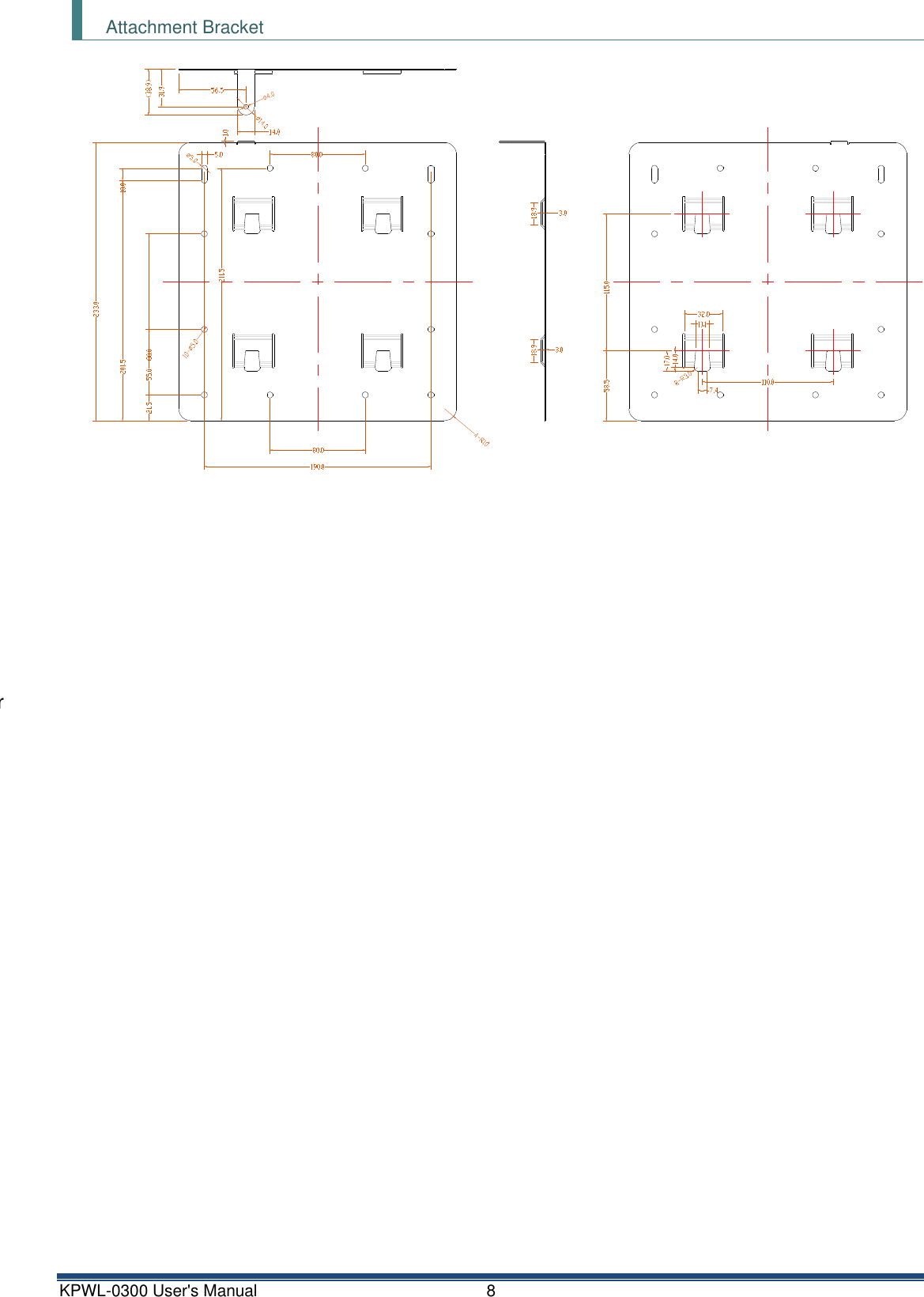
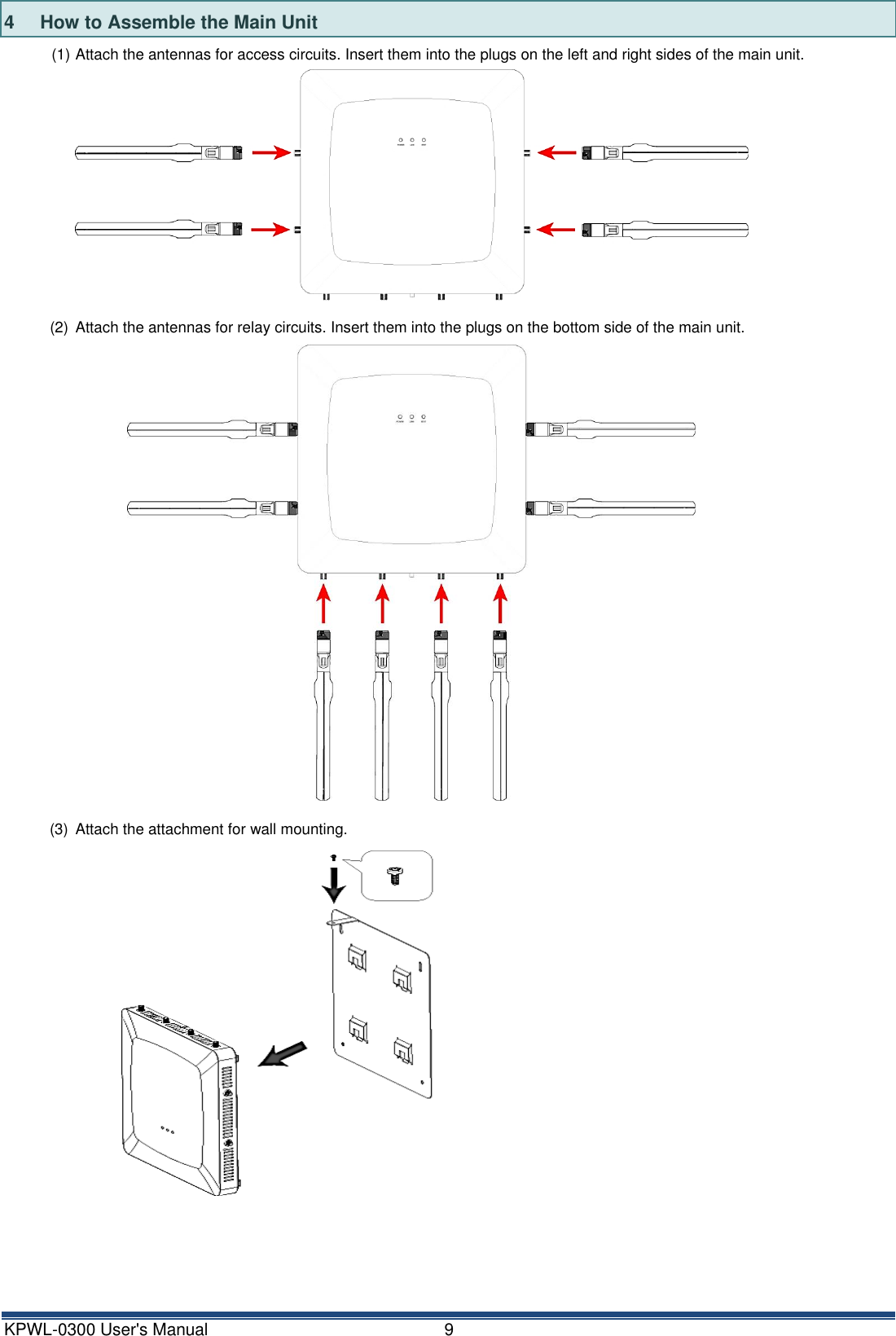
![KPWL-0300 User's Manual 7 3 Exterior View and Names of Parts Main Unit Main unit front view and rear view Main unit views (top, left, right, and bottom) Names of parts 1 2 [Main unit front view and rear view] (1) LED lamps (2) Hole for attachment for wall mounting [Main unit top view] (3) AC power cable inlet (4) Reroute button (5) LAN port (LINK2) (6) LAN port (LINK1) [Left view/right view] (7) Antenna connectors (for access circuits) (8) USB port (9) Security slot [Bottom view] (10) Antenna connectors (for relay circuits) (11) Mode switch 3 4 5 6 7 7 7 7 8 9 10 10 10 10 11](https://usermanual.wiki/Kpnetworks/KPWL0300/User-Guide-3291086-Page-8.png)
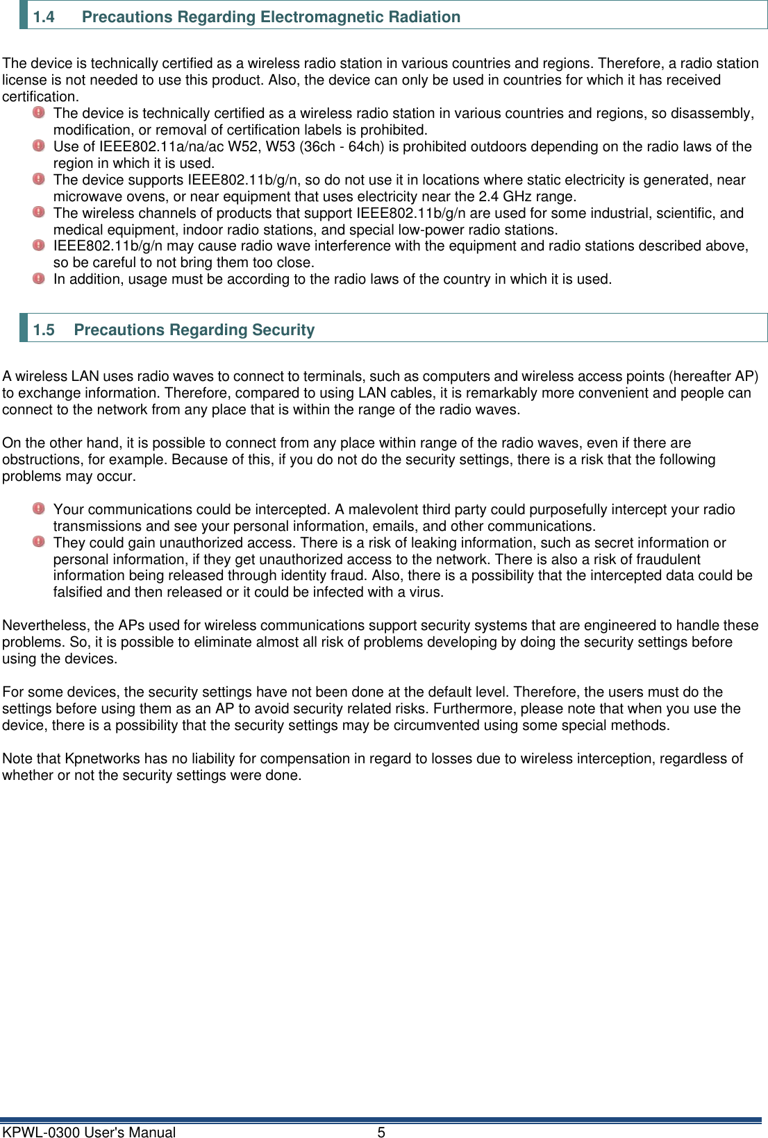
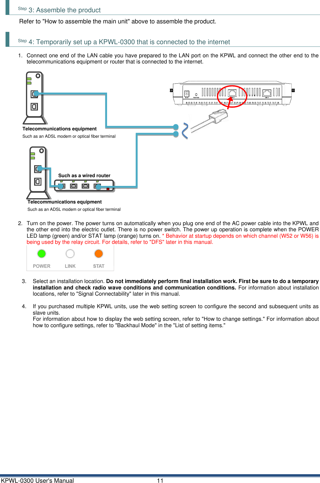
![KPWL-0300 User's Manual 10 5 Installation Method This section explains the installation method when installing the units as they are shipped. If you want to change the settings, refer to "How to change the settings" to change the settings. Step 1: Prepare the necessary equipment □ Internet accessible environment You need one LAN port for the KPWL on a device (such as a router or a hub) that is connected to the internet. □ LAN cable ………… 1 You need a cable to connect the KPWL to the internet. □ Computer with a built-in LAN port * If a there is no wired LAN port, use a USB-wired LAN adapter. □ Wi-Fi compatible terminal, such as a computer or iPhone, with a built-in LAN port □ One set KPWL Main unit, 8 antennas, AC power cable, AC adapter, mounting bracket (screw) Step 2: Check the access on the internet circuit Confirm that it is possible to connect to the internet, in advance. 1. Confirm that you have telecommunications equipment (such as a modem) that you rent or purchase from a telecommunications carrier or provider with whom you have contracted for internet access. 2. Connect the computer to telecommunications equipment or a wired router with a LAN cable. 3. Confirm that it is possible to connect to the internet under these conditions. Ex) For a computer running Windows, go to [Local Area Connections] in [Network Connections] to confirm that the IP address can be correctly acquired, and then start a browser and confirm you can display a site on the internet. 4. When you have confirmed connectivity, remove the LAN cable and proceed to the next step. Telecommunications equipment Such as an ADSL modem or optical fiber terminal Internet connection Telecommunications equipment Such as an ADSL modem or optical fiber terminal Internet connection Such as a wired router or hub Telecommunications equipment Such as an ADSL modem or optical fiber terminal Telecommunications equipment Such as an ADSL modem or optical fiber terminal Such as a wired router or hub](https://usermanual.wiki/Kpnetworks/KPWL0300/User-Guide-3291086-Page-11.png)
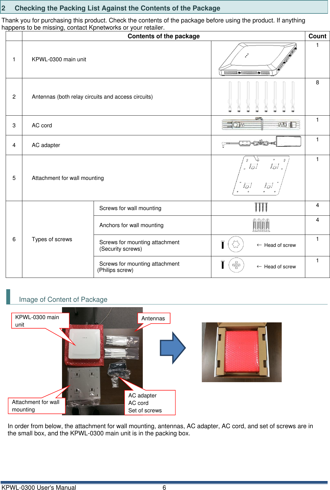
![KPWL-0300 User's Manual 13 Step 6: Connect to the internet using a Wi-Fi terminal Actually try to connect to the internet using a Wi-Fi terminal. Connect in accordance with the connection method of the applicable equipment. For Windows (Windows 7) * This is the procedure for connections if the operating environment you are using is a computer with a built-in wireless LAN running on Windows 7. * Some computers use their own independent wireless connection software. If this is the case, refer to the manual for that software. 1. Open the Control Panel 2. Click [Network and Internet], and then click [Network connections] in the Network and Sharing Center. 3. Select "KPWL-0300-******_G" or "KPWL-0300-******_A" (the ****** are the last 6 digits of the MAC address) from the wireless network connections, and then click the [Connect] button. You do not need to input a security key or passphrase because the prescribed values have not been encrypted. If you are going to use encryption for security, do the settings according to the procedures in the separate "Easy Customization" manual. 4. Confirm that your system is connected. Click the wireless network connection icon in the system tray in the bottom right of the screen, and confirm that "Connected" appears to the side of "KPWL-0300-******_G" or "KPWL-0300-******_A" (the ****** are the last 6 digits of the MAC address). 5. Start your browser and access the internet, such as by displaying a web page, to confirm the connection. For iPad, iPhone, iPod touch, etc. * This is the connection procedure for iPad version 4.2.1, but other systems can be connected in almost the same way. 1. Tap [Settings] 2. Tap [Wi-Fi] 3. Select "KPWL-0300-******_G" or "KPWL-0300-******_A" (the ****** are the last 6 digits of the MAC address) from the wireless network selections. You do not need to input a security key or passphrase because the prescribed values have not been encrypted. If you are going to use encryption for security, do the settings according to the procedures in the separate "Easy Customization" manual. 4. Return to the top page, tap [safari], and display a page on the internet to confirm the connection. For Nintendo DS, DS Lite, DSi, and DSi LL * This is the procedure for connecting on a Nintendo DSi. 1. Touch [Main Unit Settings] 2. On the third page, touch [Internet] 3. Touch [Connection Settings] 4. Select a connection from 1 to 3, and then touch [Not connected] (or [Change]) 5. Touch [Search for an access point] 6. Touch "KPWL-0300-******_G" or "KPWL-0300-******_A" (the ****** are the last 6 digits of the MAC address) in the list that appears 7. "Do you want to save this content" appears, to confirm touch [OK] 8. "Settings were saved. Connection test will start" appears, touch [OK] 9. If "Connection test was successful" appears, connection is complete.](https://usermanual.wiki/Kpnetworks/KPWL0300/User-Guide-3291086-Page-14.png)
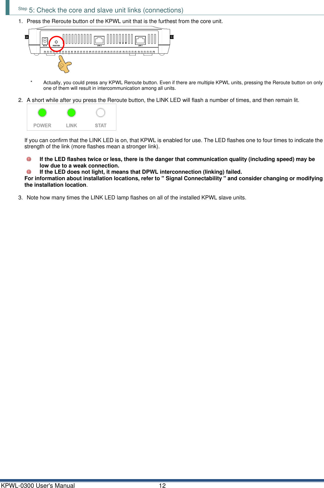
![KPWL-0300 User's Manual 14 For Sony PlayStation Portable (PSP) 1. Select [Network settings] in [Settings] 2. Select [Infrastructure mode] 3. Select [New connection settings] 4. Select [Scan] 5. Select "KPWL-0300-******_G" or "KPWL-0300-******_A" (the ****** are the last 6 digits of the MAC address) in the list that appears 6. Leave the SSID as it is, and go to the next step (→ key) 7. Leave the wireless LAN security setting as [None], and then go to the next step 8. Leave the address setting as [Easy], and then go to the next step 9. Input any connection name in "Enter the connection name". The SSID becomes the connection name if you do not change it. Go to the next step. 10. This displays the list of settings, so just go to the next step 11. Press the ○ button to save the settings 12. After [Save is complete.] appears, select [Test Connection]. After [Connecting to access point...] → [Obtaining IP Address...] → [Testing internet connection] appear, and then the connection name and the signal strength appear, the connection is complete. Step 7: Perform final installation After confirming connection of the KPWL, perform final installation. The position and the height of a temporary installation and the final installation may change somewhat. Press the Reroute button to confirm that the link is good following final installation. Step 8: Expand the wireless LAN area If you want to expand the wireless LAN area, you will need to purchase an additional KPWL-0300 unit. Perform steps 3 through 7 of this procedure on the purchased KPWL-0300 unit.](https://usermanual.wiki/Kpnetworks/KPWL0300/User-Guide-3291086-Page-15.png)
![KPWL-0300 User's Manual 16 6.1 Procedure to Change Settings This section explains how to change settings using the KPWL-0300 web screen. Step 1: Prepare the necessary equipment □ LAN cable (cross cable) ………… 1 A cross cable is required to connect the KPWL to a computer. (If the computer you are using supports Auto-MDI, connection using a standard straight LAN cable is also supported.) □ KPWL unit and its AC power cable * Installation of an antenna is not required just to configure settings. Install an antenna for connection testing and to check the radio wave intensity. □ Computer for configuring settings: Use a computer that has a wired LAN port* and web browsing capabilities. * If a there is no wired LAN port, use a USB-wired LAN adapter, etc. * The explanation here uses a computer running Windows 7, with the Internet Explorer 8.0 web browser. Step 2: Connect the KPWL-0300 unit to the computer (1) Power up the KPWL unit (connect the AC power cable). Next, connect one end of the LAN cable to the computer's LAN port and then connect the other end to the KPWL unit's LAN port. (2) Configure the computer's internet settings. 1. In Control Panel, click "Network and Internet" and then click "Network and Sharing Center." 2. Click "Local Area Connection." On the Local Area Connection Status dialog box that appears, click [Properties]. 3. In the list that appears, select "Internet Protocol Version 4 (TCP/IPv4)" and then click [Properties]. 4. Select the "Use the following IP address:" option and then input the IP address and subnet mask shown below. IP Address 192.168.3.x (x = 2 to 255) Subnet Mask 255.255.255.0 * Take a screen shot of or otherwise record the original IP address and subnet mask settings so you can restore them when necessary. 5. After inputting the settings, click [OK] to close the dialog box. 6. Click [Cancel] on the Local Area Connection Properties dialog box, and then click [Close] on the Local Area Connection Status dialog box.](https://usermanual.wiki/Kpnetworks/KPWL0300/User-Guide-3291086-Page-17.png)
![KPWL-0300 User's Manual 17 Step 3: Use the computer's browser to display the KPWL setting screen KPWL has access point function settings and relay function settings, both of which can be viewed and configured using a web browser. (1) In the browser address bar, input "192.168.3.1". This displays an authentication dialog box. (2) Input "admin" for both the user name and password, and then click [OK]. This displays the web setting screen. You can change the user name and password with the "Admin Account Settings" on the [Management] tab of the web setting screen.](https://usermanual.wiki/Kpnetworks/KPWL0300/User-Guide-3291086-Page-18.png)
![KPWL-0300 User's Manual 18 Step 4: Configure KPWL settings Displaying the web setting screen with a browser will display System Information. You can use the System Information screen to view current settings. Use the menu on the left side of the screen to select a category (page name), and the applicable setting items will appear. For information about the meaning of each setting, available settings, and more, refer to the " List of setting items " later in this manual. After all the settings are the way you want, click [Apply].](https://usermanual.wiki/Kpnetworks/KPWL0300/User-Guide-3291086-Page-19.png)
![KPWL-0300 User's Manual 19 The screen shown below will be displayed while reboot is in progress. The setup page will appear after reboot is complete. If you do not click [Apply] after updating settings, they will not be saved. For information about the settings you can configure on this page, refer to the "List of setting items" later in this manual. In addition to configuring settings, you can also reboot the KPWL unit and perform a reroute operation (the same operation performed when the Reroute button is pressed) on the web setting screen. 6.2 Initializing Settings You can use the web setting screen to initialize settings. (1) Click the [Management] tab. Next, on the side menu, click "Factory Defaults." (2) Click "Factory Defaults." You can also initialize settings from the KPWL-0300 unit. (1) Hold down the Reroute button for about 10 seconds and then release it. (2) Confirm that the LED lamps turn off momentarily, and then all lamps turn back on. (3) Confirm that the LINK light is turned off. Furthermore, if PicoManager is registered, the settings can be initialized from PicoManager also. Refer to the PicoManager manual regarding the operating procedure. Note that initializing settings causes all settings to be initialized.](https://usermanual.wiki/Kpnetworks/KPWL0300/User-Guide-3291086-Page-20.png)
![KPWL-0300 User's Manual 20 6.3 Remote Settings If the KPWLs that configure the network are mutually connected using relay circuits, it is possible to do the access circuit settings of each KPWL from a computer connected to the core (parent) wired LAN. Specify the IPv6 address that was automatically assigned to the main unit. With remote settings, you can also specify rebooting or rerouting by operations from the web page. These operations are effective when the KPWL-0300s are already installed, for instance if the installation is in a high location or there are many passersby, so it is not possible to work near the devices. However, there is a precondition that the relay circuits have been established (so that KPWL-0300 units can interactively communicate), so changes cannot be made to devices (slave 4 in the example in the diagram) that are not linked due to communications obstructions, etc. Also, for the same reason, remote setting changes cannot be done to the relay circuits (the links break if the relay circuit settings are changed). Slave -1 Mac:xx-xx-xx-63-07-08 IPv6: fd00:5043::ae64:ddff:fe63:0708 Such as a wired router or hub Slave -3 Mac:xx-xx-xx-60-01-02 IPv6: fd00:5043::ae64:ddff:fe60:0102 Slave -2 Mac:xx-xx-xx-63-04-05 IPv6: fd00:5043::ae64:ddff:fe63:0405 Core Mac:xx-xx-xx-69-0A-0B IPv6: fd00:5043::ae64:ddff:fe69:0A0B Slave -4 Mac:xx-xx-xx-6C-0D-0E IPv6: fd00:5043::ae64:ddff:fe6c:0d0e It is possible to set the access circuits of the KPWL-0300 core and slaves-1 to -3. Example) By inputting " http://[fd00:5043::ae64:ddff:fe60:0102]/" in the address bar, You can access the web setting page of slave-3. The access circuits can be set or rebooted/rerouted from the web.](https://usermanual.wiki/Kpnetworks/KPWL0300/User-Guide-3291086-Page-21.png)
![KPWL-0300 User's Manual 21 Accessing the KPWL-0300 with an IPv6 Address The KPWL-0300 can be accessed with an IPv6 address. Computer Settings 1) Display Control Panel. 2) Click "Network and Sharing Center." 3) Click "Change adapter settings." This displays a Network Connections screen. 4) Right-click the wired LAN interface (Local Area Connection, etc.), and then click "Properties." 5) Select "Internet Protocol Version 6 (TCP/IPv6)" and then click [Properties]. 6) Select the "Use the following IP address:" option and then configure the settings as described below. IPv6 Address Any IPv6 address starting with "fd00:5043::". Example: fd00:5043::xxxx:xxxx:xxxy:yyyy * For the part of the address inside the rectangular boundary above, specify any hexadecimal number. Note, however that you should not use the following for the red characters: ae64:ddff:fe6. * If you do not want to specify anything in particular for the part within the rectangular boundary, specify the address below. "fd00:5043::1111:2222:3333:4444" Subnet Prefix Length 64 * Other fields can be left blank.](https://usermanual.wiki/Kpnetworks/KPWL0300/User-Guide-3291086-Page-22.png)
![KPWL-0300 User's Manual 22 Calculating a Device's IPv6 Address 1) Check the serial number on the label affixed to the back of the device. * The following steps are performed using the serial number above. 2) A serial number is made up of a series of two-digit values. AC / 64 / DD / 60 / 00 / BE 3) The final six digits of the divided serial number shown in step 2 are positioned in the address as shown below. fd00:5043::ae64:ddff:fe60:00be The above value is the device's IPv6 address. Note the precautions below when calculating an IPv6 address. • The black characters (fd00:5043::ae64:ddff:fe) in the above address are fixed. Do not change them. • Input two colons between the 5043 and ae64 parts of the fixed address. Specifying the URL of the Management Page Input the calculated IP address in the browser address bar. Input the calculated IP address that was calculated as described in the example above in "Calculating a Device's IPv6 Address", as shown below. http://[fd00:5043::ae64:ddff:fe60:00be]/ * Make sure you do not forget to include square brackets ([ and ]) at the beginning and end of the iPv6 address.](https://usermanual.wiki/Kpnetworks/KPWL0300/User-Guide-3291086-Page-23.png)
![KPWL-0300 User's Manual 26 MAC Filter With "MAC Filter", you can add MAC addresses to be used for items that were set in "Additional Authentication" in "Security" on the side menu. Input a MAC address and click [Add]. The added MAC address can be confirmed in the MAC address filter table. QoS With "QoS", you can do the settings to assign priority for specific communications. You can set both the access point (AP) side and the station (ST) side. You can set the priorities for the following parameters. Low (background: BK), Normal (best effort: BE), priority (video: VI), and highest priority (audio: VO). Item Description Values that can be set Default value (AP) Default value (ST) CWmin You can specify the minimum value for the contention window that is used for the frame collision avoidance configuration. Generally, the smaller the value, the higher the probability of acquiring transmission rights. 1 to 15 alphanumeric characters BK: 4 BE: 4 VI: 3 VO: 2 BK: 4 BE: 4 VI: 3 VO: 2 CWmax You can specify the maximum value for the contention window. 1 to 15 alphanumeric characters BK: 10 BE: 6 VI: 4 VO: 3 BK: 10 BE: 10 VI: 4 VO: 3 AIFSN You can specify the frame transmission interval slot (number of windows). The smaller the transmission interval, the higher the priority. 1 to 15 alphanumeric characters BK: 7 BE: 3 VI: 1 VO: 1 BK: 7 BE: 3 VI: 2 VO: 2 TxOP You can specify the time that can be appropriated when acquiring transmission rights. The higher this value is, the larger amount of data can be sent at one time, but the real-time performance is reduced. 1 unit is 32 ms. If you specify 0, then each transmission is 1 frame only. 0 to 256 BK: 0 BE: 0 VI: 94 VO: 47 BK: 0 BE: 0 VI: 94 VO: 47](https://usermanual.wiki/Kpnetworks/KPWL0300/User-Guide-3291086-Page-27.png)
![KPWL-0300 User's Manual 28 Basic Settings Item Description Values that can be set Prescribed value Backhaul Mode You can specify whether to treat the device as a core unit or slave unit. Slave, Core Slave Band You can specify in which mode, IEEE 802.11a, n, or ac, to operate. 11a, 11a/n, 11a/n/ac 11a/n/ac Channel You can specify the channels that are used. The values that can be set vary depending on the value specified for "Band". • For 11a: 36 ch to 140 ch • For 11a/n: 38 ch to 134 ch • For 11a/n/ac: 42 ch to 122 ch • For 11a: 36 ch • For 11a/n: 38 ch • For 11a/n/ac: 106 ch Automatic Channel Selection You can specify whether to automatically select unused channels when scanning for channels at startup. ON, OFF OFF Indoor/Outdoor Specify whether to use the device indoors or outdoors. By selecting outdoor, you are prevented from selecting channels that are prohibited from use outdoors by accident. Indoor, Outdoor Indoor Channel Bandwidth The values that can be set vary depending on the value specified for "Band". • For 11a: Fixed at 20 MHz • For 11a/n: 20 MHz, 40 MHz • For 11a/n/ac: 20 MHz, 40 MHz, Auto 80/40/20 MHz • For 11a: 20 MHz • For 11a/n: 40 MHz • For 11a/n/ac: Auto 80/40/20 MHz Tx Power You can specify the strength of the wireless output. The larger it is, the higher the output. 1 to 12 12 SafeZone You can specify whether to allow encryption of the relay circuits. ON (performed) / OFF (not performed) ON SafeKey Devices that have the same value are considered to belong to the same network so intercommunication is possible. If they are different, relaying is not possible. This is how networks are separated. 1 to 64 single-byte alphanumeric characters picocela AP Control You can specify whether to detect when the upstream circuit is cut off and automatically turn off the access point function. ON, OFF ON Waiting time for turning off AP If you selected ON for "AP Control", specify the time that the access point function is automatically turned off. 60 Reroute Clicking [Execute] implements rerouting. * You can set the "Band", "Channel", and "Channel Bandwidth" on the access point (5 GHz) on this page. For details, refer to "Basic Settings" in "Items that can be set in the "Access Point" tab".](https://usermanual.wiki/Kpnetworks/KPWL0300/User-Guide-3291086-Page-29.png)
![KPWL-0300 User's Manual 30 Expanded Settings Item Description Values that can be set Prescribed value Periods for IPT (0-65535) Manually specify the values related to IPT in reference to backhaul operations. Normally, operation of the values in these places is not required. Leave the default value (0) as it is. 0 to 65535 0 Option Specify the optional values if special options have been incorporated. Normally, operation of the values in these places is not required. Leave the default value as it is. 00000000000000000000 00000000000000000000 00000000000000000000 Items that can be set in the "Management" tab Admin Account Settings Item Description Values that can be set Prescribed value Administrator Name You can specify a user name for accessing the web setting page. Single-byte alphanumeric characters admin Administrator Password You can specify a password for accessing the web setting page. Single-byte alphanumeric characters admin Management Protocol If you select this check box, you can do the following settings related to SNMP. SNMP Version You can specify the SNMP version. v1/v2c v1/v2c SNMP Get Community You can specify the SNMP Get Community. Single-byte alphanumeric characters public SNMP Set Community You can specify the SNMP Set Community. Single-byte alphanumeric characters private Factory Default You can initialize settings by using "Factory Default". Click [Factory Default] to initialize the settings. Date and Time Item Description Values that can be set Prescribed value Local Time You can set the local time. By clicking [Acquire Current Time from Your PC], you can set it to the time that is set for the PC you are using. Use NTP If you select this check box, you can do the following settings related to NTP (Network Time Protocol). Server Name You can set this if "Use NTP" was enabled. You can specify the NTP server name that is used. User-Defined Update Interval You can set this if "Use NTP" was enabled. You can specify the update interval for the date and time used for NTP. 24 Time Zone You can set the time zone. (GMT + 09:00) Osaka, Sapporo, Tokyo](https://usermanual.wiki/Kpnetworks/KPWL0300/User-Guide-3291086-Page-31.png)
![KPWL-0300 User's Manual 31 System Log In the "System Log", you can confirm the system log. By clicking [Save], you can save data in a log format. Clicking [Refresh] updates the system log display to the newest status. Syslog Server Item Description Values that can be set Prescribed value Transfer Logs If you select this check box, the system log used by the Syslog Server can be transferred. You can specify the Syslog Server name in the input field. Single-byte alphanumeric characters Copy Logs to Attached USB Device If you select this check box, the system log is copied to a USB device. E-mail Logs If you select this check box, the changes in the system log are sent via email. E-mail Subject You can specify the e-mail subject line. Any subject line Interval You can specify the interval at which e-mails are sent. Half hour, One hour, Two hours, Half day, One day, Two days Half hour SMTP Server Address You can specify the SMTP server address. Single-byte alphanumeric characters SMTP Server Port You can specify the SMTP server port. Single-byte alphanumeric characters Sender E-mail You can specify the e-mail address of the sender. Single-byte alphanumeric characters Receiver E-mail You can specify the e-mail address of the receiver. Single-byte alphanumeric characters Authentication Specify the method to authenticate and connect to the mail server. • Disable: No Authentication • SSL: Authentication and connection via SMTP over SSL • TLS: Authentication and connection using STARTTLS Disable, SSL, TLS Disable Account You can specify the user ID for the e-mail server. Single-byte alphanumeric characters Password You can specify the password for the e-mail server. Single-byte alphanumeric characters Firmware Upgrade You can update the firmware by using "Firmware Upgrade". For details, refer to "Updating Firmware from the Webpage" later in this manual. Reboot With "Reboot", you can reboot the KPWL-0300. Clicking [Reboot], reboots the KPWL-0300.](https://usermanual.wiki/Kpnetworks/KPWL0300/User-Guide-3291086-Page-32.png)

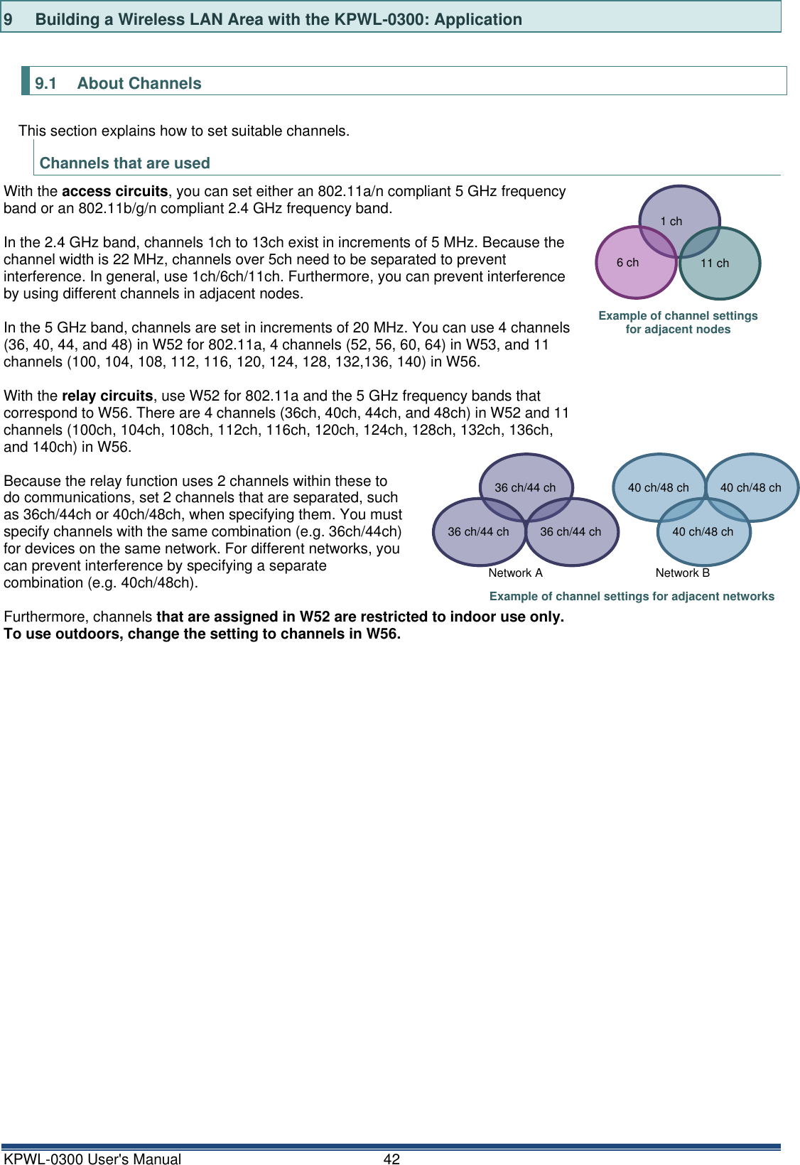
![KPWL-0300 User's Manual 43 How to Search for Overlapping Channels Due to the popularization of wireless LAN, several access points may be installed in office buildings and apartments. Wireless quality may decline considerably because of overlapping channels, mutual interference, etc. As a result, it is important to search for frequencies that are being used in the area of installation and do your best to set channels so that they do not overlap. Many tools for searching for frequency bands that are being used are available, both for free or for sale. This section introduces a way to search for frequencies that are in use by using freeware3 for Windows, called "InSSIDer2". 1. Prepare a computer, such as a laptop, equipped with Windows that can be carried to the installation locations, and then open the following site. http://inssider.softonic.jp/ 2. Click [Free download] The download does not start immediately, it stops until you have moved to the page, and then starts in about 15 seconds4. 3. Execute the inSSIDer-Installer-2.x.x.xxxxxx.exe5 that you downloaded and install it. 4. Start inSSIDer2. 5. Clicking "Start" at the top right displays a list of access points on the upper half of the screen. RSSI is the wireless strength and Channel is the channel. You can check which access points are using which channels and their strength. 3 Ver4 and later of inSSIDer requires a fee ($19.99). Understand that, although you can currently download free versions from places like softonic, future distribution cannot be guaranteed. 4 "To help protect your security, Internet explorer blocked this site from downloading files to your computer. Click here for options ..." appears on the top part of the page in Internet Explorer. Click it, and then select "Download file". 5 As of July 20, 2011, the newest version is inSSIDer-Installer-2.0.7.0126.exe.](https://usermanual.wiki/Kpnetworks/KPWL0300/User-Guide-3291086-Page-44.png)
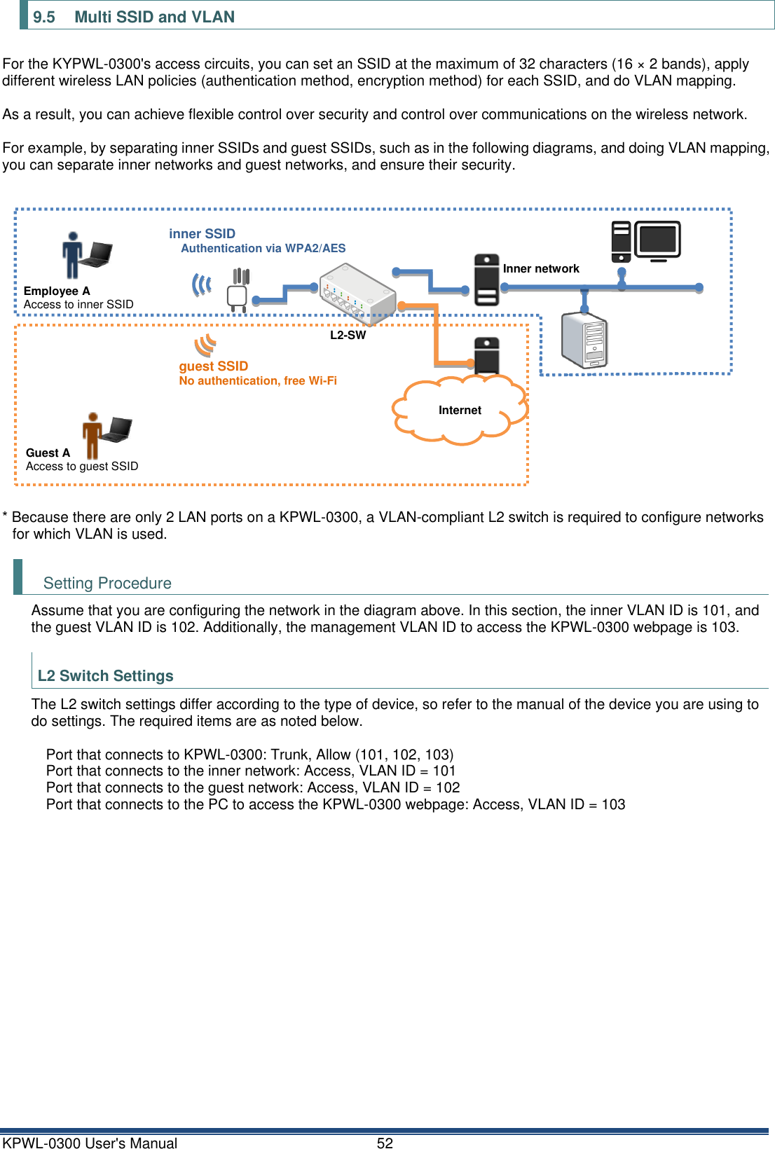
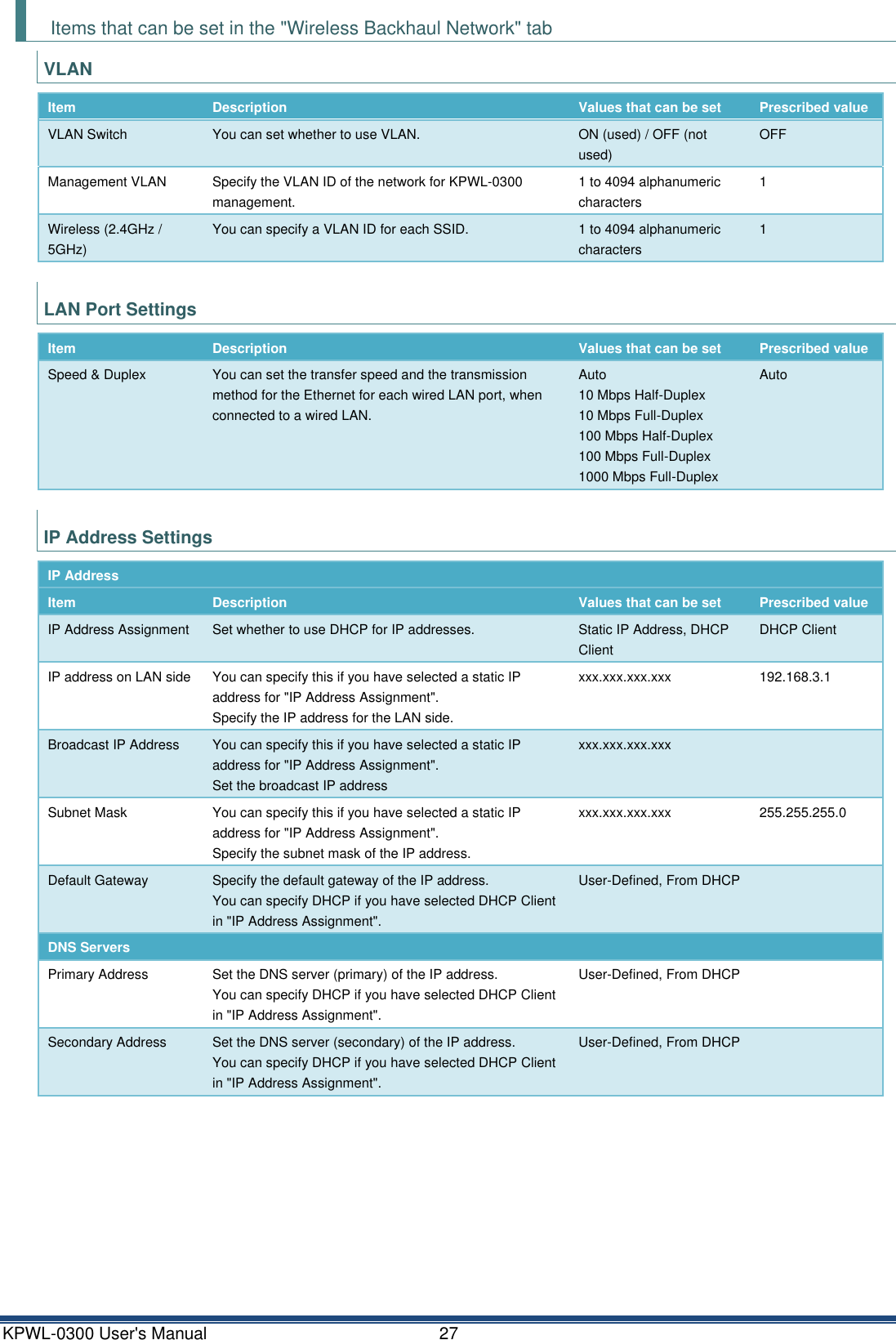
![KPWL-0300 User's Manual 53 KPWL-0300 Settings You can do settings on the web setting screen. For information about the IP address for the web setting screen, refer to the chapter, "How to change settings". • Setting procedure 1) Click the [Wireless Backhaul Network] tab, and then click [VLAN] from the side menu. 2) Turn on [VLAN Switch], and then input each VLAN ID as follows. • Management VLAN: 103 • SSID 1: 101 • SSID 2: 102 3) Click [Apply] to enable the settings. 4) Click the [Access Point] tab, and then click [Basic Settings] from the side menu. 5) Enable [Wireless], and then input the SSID names as follows. • SSID 1: inner SSID • SSID 2: guest SSID 6) Click [Apply] to enable the settings.](https://usermanual.wiki/Kpnetworks/KPWL0300/User-Guide-3291086-Page-54.png)
![KPWL-0300 User's Manual 54 7) Click [Security] from the side menu. 8) Select "inner SSID" in [SSID], and then set the following. • Authentication Method: MPA-PSK • WPA Type: WPA2 • Encryption Type: AES • Pre-shared Key: Any passphrase 9) Click [Apply] to enable the settings. 10) Select "guest SSID" in [SSID], and then set the following. • Authentication Method: No Authentication 11) Click [Apply] to enable the settings.](https://usermanual.wiki/Kpnetworks/KPWL0300/User-Guide-3291086-Page-55.png)
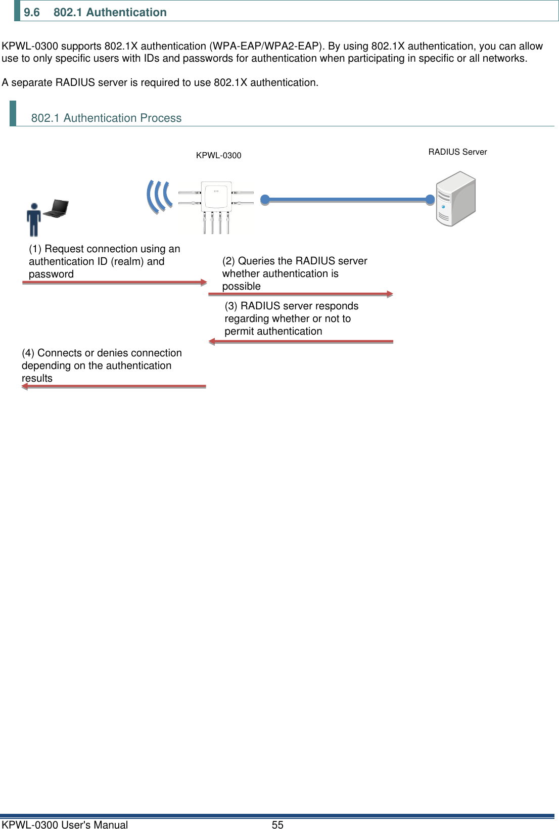
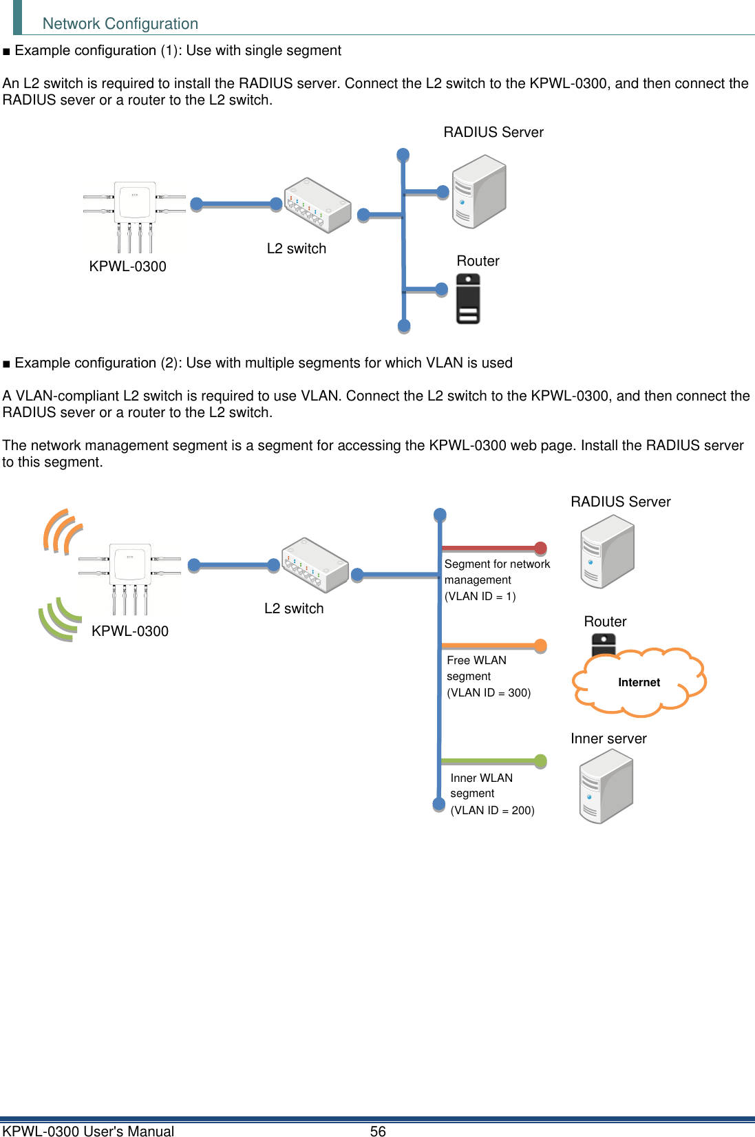
![KPWL-0300 User's Manual 57 Setting Procedure RADIUS Server Settings How to set the RADIUS server differs according to the type of device, so refer to the manual of the device you are using to do settings. KPWL-0300 RADIUS Server Settings You can do settings on the web setting screen. For information about the IP address for the web setting screen, refer to the chapter, "How to change settings". • Setting procedure 1) Click the [Access Point] tab, and then click [Security] from the side menu. 2) Select either [IEEE802.1x/EAP] or [WPA-EAP] from [Authentication Method], or select [MAC RADIUS authentication] from [Additional Authentication]. Items appear for setting the RADIUS Server. 3) Do settings for the RADIUS Server. • RADIUS Server: Specify the IP address for RADIUS Server. • Authentication Port: Specify the port number for RADIUS Server. (Normally keep this 1812) • Shared Secret: Specify if a secret key has been set for RADIUS Server. 4) Click [Apply] to enable the settings. To separate segments and use multiple VLANs, refer to "Multi SSID and VLAN" above and do the VLAN settings.](https://usermanual.wiki/Kpnetworks/KPWL0300/User-Guide-3291086-Page-58.png)

![KPWL-0300 User's Manual 59 Setting Procedure You can do settings for both unicasting and multicasting on the web setting screen. For information about the IP address for the web setting screen, refer to the chapter, "How to change settings". Doing Unicasting Settings 1) Click the [Access Point] tab, and then click [Security] from the side menu. 2) Select either [Disable], [STA Separator], or [SSID Separator] in [Wireless Client Isolation]. * Refer to "Wireless Client Isolation" below for details on permitting and/or not permitting communications depending on the setting items and setting results for [Wireless Client Isolation]. 3) Click [Apply]. Unicasting is enabled. Wireless Client Isolation ■ Items that can be set with [Wireless Client Isolation] • Disable: Terminals that are connected to the same AP can communicate with each other. • STA Separator: Terminals that are connected to the same AP cannot communicate with each other. • SSID Separator: Terminals that are connected using the same SSID for the same AP can communicate with each other. However, terminals that are connected using different SSIDs, even on the same AP, cannot communicate with each other. ■ Communications that are permitted/not permitted depending on the setting results of [Wireless Client Isolation] • When two terminals are connected to different SSIDs When assuming that Terminal A is connected to SSID #1 and Terminal B is connected to SSID #2, communications between Terminal A and Terminal B are permitted/not permitted as noted below. [Wireless Client Isolation] settings Permitting/not permitting communications between Terminal A and Terminal B SSID #1 settings SSID #2 settings Disable Disable Can STA Separator Disable Cannot SSID Separator Disable Cannot STA Separator SSID Separator Cannot STA Separator STA Separator Cannot SSID Separator SSID Separator Cannot](https://usermanual.wiki/Kpnetworks/KPWL0300/User-Guide-3291086-Page-60.png)
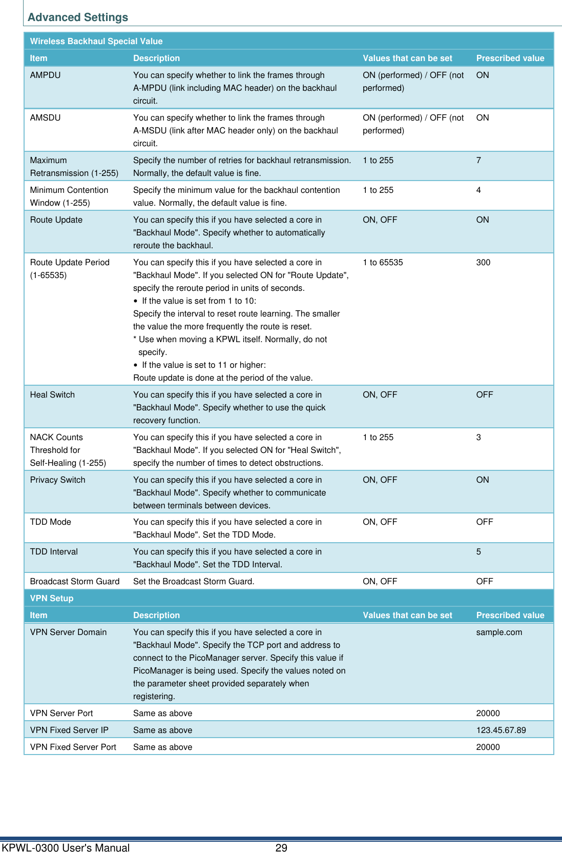
![KPWL-0300 User's Manual 60 • When two terminals are connected to the same SSID When assuming that both Terminal A and Terminal B are connected using an SSID, communications between Terminal A and Terminal B are permitted/not permitted as noted below. [Wireless Client Isolation] settings Permitting/not permitting communications between Terminal A and Terminal B Disable Can STA Separator Cannot SSID Separator Can Doing Multicasting Settings 1) Click the [Wireless Backhaul Network] tab, and then click [Advanced Settings] from the side menu. 2) Select [ON] in [Privacy Switch]. * This item can only be set on the parent (core). The child (slave) takes over the settings of the parent (core). 3) Click [Apply]. Multicasting is enabled.](https://usermanual.wiki/Kpnetworks/KPWL0300/User-Guide-3291086-Page-61.png)
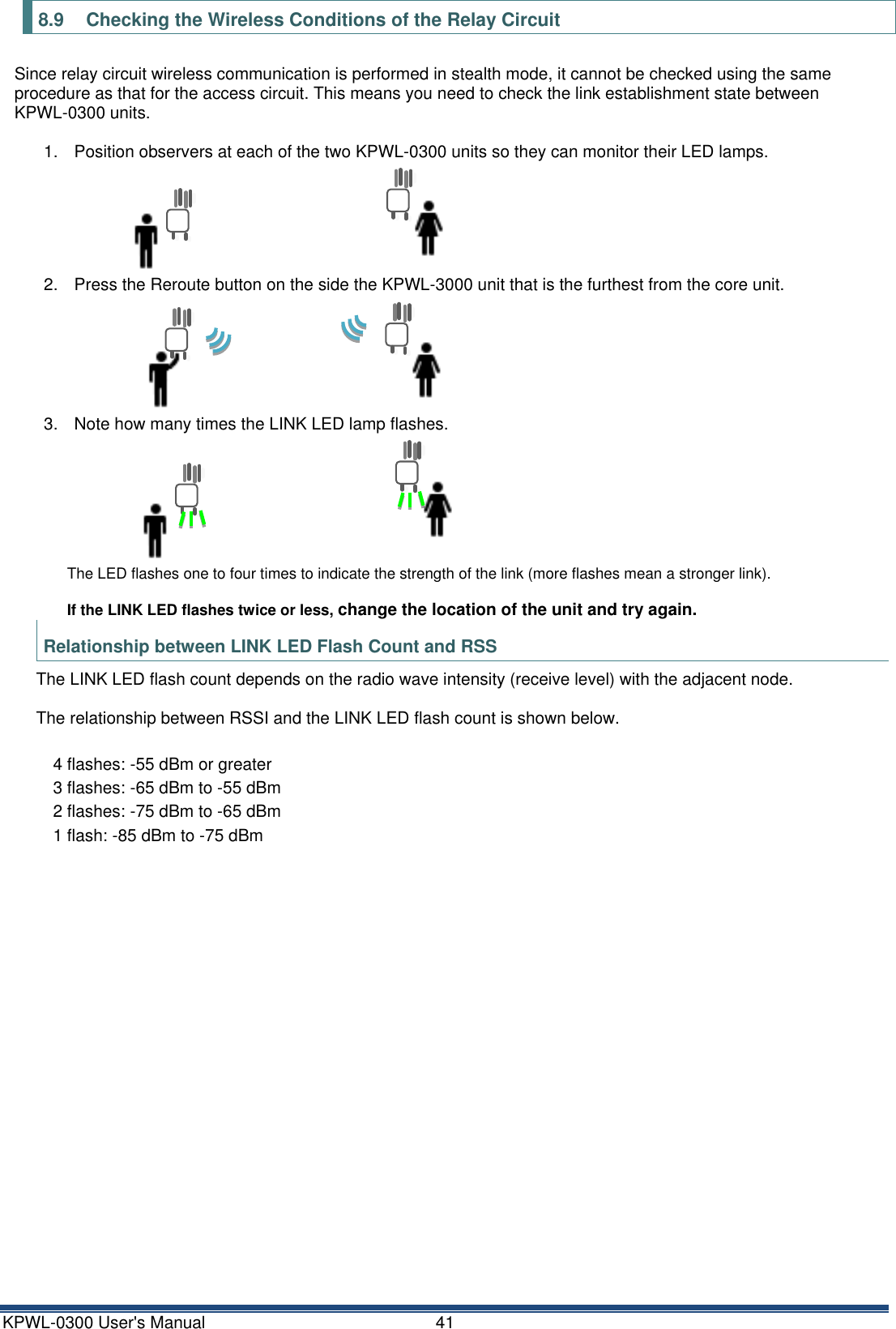
![KPWL-0300 User's Manual 61 10.2 Relay Circuit Radio Wave Intensity There are two methods for checking relay circuit radio wave intensity. One method is to press the Reroute button and observe how many times the LINK LED flashes. The LINK LED will flash one to four times. More flashes indicate greater radio wave intensity. The second method is to check the RSSI values on the web setting screen. Click the [Wireless Backhaul Network] tab. Next, on the side menu, click "System Information" to display the RSSI Table. Note however that the second method can be used for a slave node only. Since there are no nodes above the core node, the table is not displayed for it. Mac address MAC address E (RSSI) RSSI value successive average E (dbm) dBm value successive average V (RSSI) RSSI value variance RSSI Newest RSSI (Not a real-time value) Count Counter (Not a Routing Index)](https://usermanual.wiki/Kpnetworks/KPWL0300/User-Guide-3291086-Page-62.png)
![KPWL-0300 User's Manual 62 10.3 Checking the Relay Route The relay route can be checked with the web setting screen. Click the [Wireless Backhaul Network] tab. Next, on the side menu, click "System Information" to display relay route information. * Displayed for the core node only. Node Mac address Node MESH MAC address Parent Mac address Node directly above (MESH MAC) hop num Number of hops from the core type Type (core or slave unit) web UI Link to the slave unit web UI (IPv6 address) * For information about the IPv6 address, refer to "Remote settings" earlier in this manual. A constructed route (topology) can be divided by combining Hop and Parent.](https://usermanual.wiki/Kpnetworks/KPWL0300/User-Guide-3291086-Page-63.png)
![KPWL-0300 User's Manual 63 10.4 Updating Firmware from the Webpage Firmware can be updated from the web setting screen. • Update Procedure 1) Click the [Management] tab. Next, on the side menu, click "Firmware Upgrade." 2) Click [Browse] and then select the firmware file (KPWL-0300-FW-V******.bin). (****** is the version number.) 3) Click "Update." This displays a dialog box. 4) Click [OK] twice. This starts the firmware update. * The device will not respond for a number of minutes while firmware is being updated. Do not turn off the devices during the update. 5) Reboot starts after the firmware update is finished. Wait until the reboot is complete. 10.5 If You Forget Your Login Password If you change the password used to access the web management screen (Default: admin) and then forget it, you will need to restore factory default settings. For information about how to restore factory default settings, refer to "6.2 Initializing Settings." If you forget the password you will not be able to access the web management screen. You will need to use PicoManager. Note that returning settings to their factory defaults will cause all settings to be initialized.](https://usermanual.wiki/Kpnetworks/KPWL0300/User-Guide-3291086-Page-64.png)