Kronegger FORT-9912-2009 RFID Reader Module User Manual
Kronegger GmbH RFID Reader Module
user manual

Kronegger GmbH
Parkring 1
A-8074 Grambach
Austria
Phone +43 (0) 316-403125
Kronegger XXL+ P&P Reader
Version 2.0
User - Manual

Documentation Kronegger XXL+ P&P Reader
19.4.12
Kronegger GmbH 2
Table of Contents
Table of Contents .................................................................................................... 2
1 Introduction ..................................................................................... 3
2 Getting Started ................................................................................ 4
3 Instruction Set ................................................................................. 5
Generic Commands – Overview ............................................................................. 5
4 Hardware ......................................................................................... 6
4.1 Features ....................................................................................................... 6
4.2 Dimensions:.................................................................................................. 7
4.3 Pinout ........................................................................................................... 7
4.4 Electrical characteristics of Connector1: ...................................................... 8
4.5 Electrical characteristics of Connector2: ...................................................... 9
5 Integration ..................................................................................... 10

Documentation Kronegger XXL+ P&P Reader
19.4.12
Kronegger GmbH 3
1 Introduction
Kronegger GmbH. provides customer support and optional design in services for
properly integrating the products. Since we do not have full information on customer‟s
applications or products, it is due to the customer to verify that the integrated
products are suitable for the application intended and that no patents or intellectual
property rights are infringed. Integrating the products into the customer‟s application
is a development process that requires special experience, professional skills and
involves usual technical risks. Kronegger GmbH. assumes no responsibility or liability
for customer‟s applications, their performance, the required development effort,
production, installation, operation, their suitability, reliability and safety. The products
are not designed for applications where malfunction could cause potential risk of
death, personal injury or environmental damage.
Any changes or modifications not expressly approved by the party responsible for
compliance could void the user's authority to operate the equipment.
If using a permanently affixed label, the modular transmitter must be labeled with its
own FCC identification number, and, if the FCC identification number is not visible
when the module is installed inside another device, then the outside of the device
into which the module is installed must also display a label referring to the enclosed
module. This exterior label can use wording such as the following: “Contains
Transmitter Module FCC ID ZKCFORT-9912-2009 or contains FCC ID ZKCFORT-
9912-2009”. Any similar wording that expresses the same meaning may be used.
The Grantee may either provide such a label, an example of which must be included
in the application for the equipment authorization, or, must provide adequate
instructions along with the module which explains this requirement. In the latter case,
a copy of these instructions must be included in the application for equipment
authorization.
This device complies with part 15 of the FCC rules. Operation is subject to the
following two conditions: (1) This device may not cause harmful interference, and (2)
This device must accept any interference received, including interference that may
cause undesired operation.
The manual has been written to the best of our knowledge. We do not guarantee the
correctness and completeness of the provided information and insist on the good
practice of crosschecking during the customer‟s development process through
sufficient testing coverage. Feedback on errors in the manual are highly appreciated.
This document may be used to support the integration of Kronegger products. Any
other use, duplication, storage or circulation is not authorized shall be prosecuted as
a violation of copyright laws.

Documentation Kronegger XXL+ P&P Reader
19.4.12
Kronegger GmbH 4
2 Getting Started
As factory default the data are transmitted at 115200, n, 8, 1 and no handshake. Two
protocol modes are available. As default the binary protocol is used. To change the
protocol type or the baud rate you have to configure the EEPROM (see EEPROM
Memory Organization).
First of all you need a Mifare+ reader with an USB cable (Type A to mini B)
For the communication with the reader you have to download a virtual com-port
driver (VCP) for the USB interface. Please check the following link for the latest
version:
http://www.ftdichip.com/Drivers/VCP.htm
The driver will map the USB to a serial communication port. Install the driver and
connect the reader. It will show “new hardware detected.” You can check your setup
under System Setting/System/Hardware/Device Manager to find out which com-port
had been assigned to your reader. Optionally you can change the com number in the
advanced settings of the com-port.
For the communication with the reader you need the ReaderTool which is delivered
with any Kronegger Reader. The Microsoft .NET Framework 2.0 (or any higher
version) needs to be installed first in order to run the ReaderTool:
http://www.microsoft.com/downloads/details.aspx?familyid=0856EACB-4362-4B0D-
8EDD-AAB15C5E04F5&displaylang=en
The ReaderTool needs no installation, simply start it and the reader will be selected
automatically. Now you can communicate with your Mifare+ reader.
Step by Step:
Download and install the FTDI driver
Connect the Reader via the USB cable to the PC
Download and install the Microsoft .NET Framework
Start the ReaderTool
Now you can communicate with the reader
Documentation Kronegger XXL+ P&P Reader
19.4.12
Kronegger GmbH 5
3 Instruction Set
Following table describes all commands of the reader device. Each command sends
a response to the host. Exceptions are mentioned explicitly. The green LED is
acknowledging a successfully executed command. The red LED indicates an error.
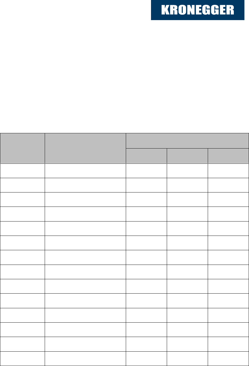
Generic Commands – Overview
Generic commands apply to all supported tags.
Command
Description
Applicable OEM
Micro
Plus
XXL
„b‟
Get Serial Number
'c'
Continuous Read
„e‟
Send SAM APDU
„k‟
Lock Block
'poff '/'pon'
Antenna Power off/on
'pp'
Set/Get User ports
„pr‟/‟pw‟
Read/Write User ports
're'
Read EEPROM register
's'
Select
„t‟
Send 14443-4 APDU
'v'
get Version
„vs‟
Set Version
'we'
Write EEPROM register
'x'
Reset

Documentation Kronegger XXL+ P&P Reader
19.4.12
Kronegger GmbH 6
4 Hardware
4.1 Features
Dimensions 73,0 x 67,0 x 10,0 (LxWxH) ±1 mm
45,0 x 70,0 x 10,0 (LxWxH) ±1 mm (only P&P small)
Antenna on board
Interface type RS232
Reading distance up to 50mm depending on tag
Signaling reading LED, power LED
Power supply 5, 12 VDC ±10% regulated
Documentation Kronegger XXL+ P&P Reader
19.4.12
Kronegger GmbH 7
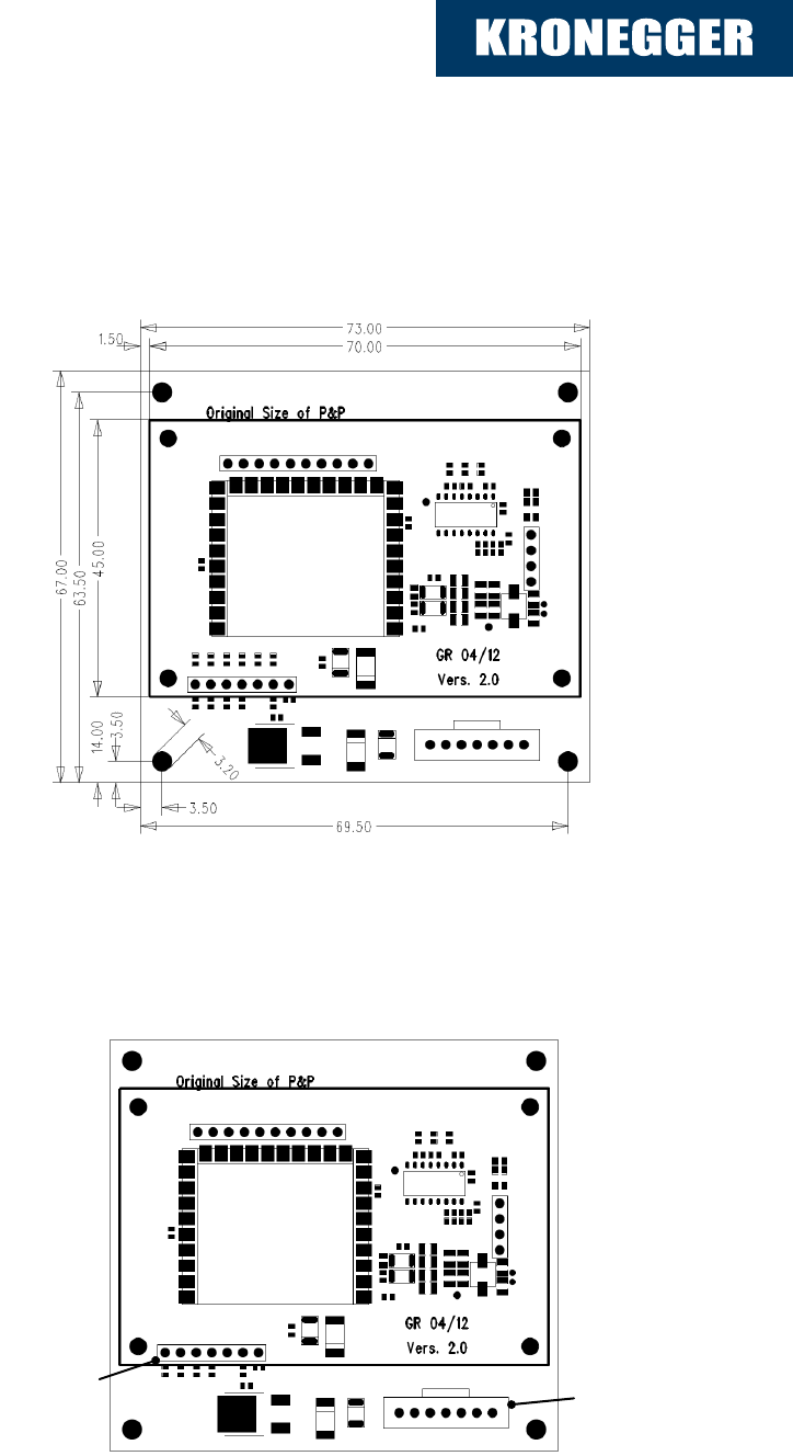
4.2 Dimensions:
All dimensions listed in mm
PCB thickness: 1,5 ± 0.1 mm
4.3 Pinout
Connector1
Connector2
7
6
5
4
3
2
1
7
6
5
4
3
2
1

Documentation Kronegger XXL+ P&P Reader
19.4.12
Kronegger GmbH 8
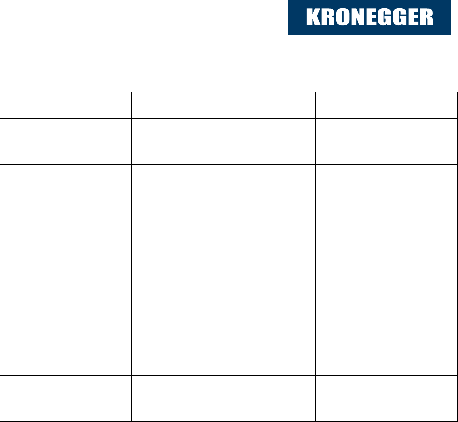
4.4 Electrical characteristics of Connector1:
PIN
PIN No.
Min.
Typ.
Max.
Description
RFU
1
NC
VCC1
2
4,5 V
5,0 V
150 mA
5,5 V
250 mA
Supply Voltage
Supply Current
GND
3
GND
Ground for Power
Supply and Interface
RX
RS232
4
-30 V
3 kΩ
5 kΩ
+30 V
7 kΩ
RS232 Voltage Levels
Input Impedance
TX
RS232
5
±5 V
300 Ω
±9 V
RS232 Voltage Levels
Output Impedance
RX
TTL
6
3,3 V
8 mA
5,5 V
25 mA
TTL Input from Host
TX
TTL
7
3,3 V
8 mA
3,6 V
25 mA
TTL Output to Host
Documentation Kronegger XXL+ P&P Reader
19.4.12
Kronegger GmbH 9
4.5 Electrical characteristics of Connector2:
PIN
PIN No
Min.
Typ.
Max.
Description
VCC2
1
11 V
12 V
150 mA
13 V
250 mA
Supply Votage
Supply Current
RFU
2
RFU
GND
3
GND
Ground for Power
Supply and interface
RX
RS232
4
-30 V
3 kΩ
5 kΩ
+30 V
7 kΩ
RS232 Voltage Levels
Input Impedance
TX
RS232
5
±5 V
300 Ω
±9 V
RS232 Voltage Levels
Output Impedance
RX
TTL
6
3,3 V
8 mA
5,5 V
25 mA
TTL Input from Host
TX
TTL
7
3,3 V
8 mA
3,6 V
25 mA
TTL Output to Host
Documentation Kronegger XXL+ P&P Reader
19.4.12
Kronegger GmbH 10
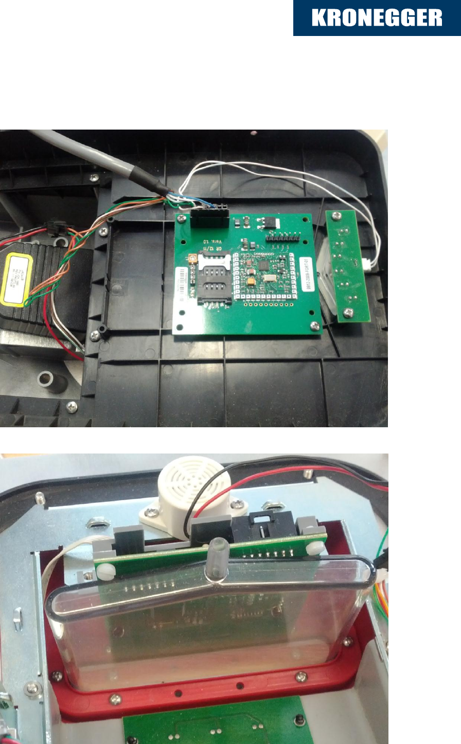
5 Integration
Documentation Kronegger XXL+ P&P Reader
19.4.12
Kronegger GmbH 11
Version History
Date
Revision Number
19.04.2012
Version 2.0