Kronegger FORT-9912-5018 RFID Reader User Manual
Kronegger GmbH RFID Reader
user manual

Kronegger GmbH
Parkring 1
A-8074 Grambach
Austria
Phone +43 (0) 316-403125
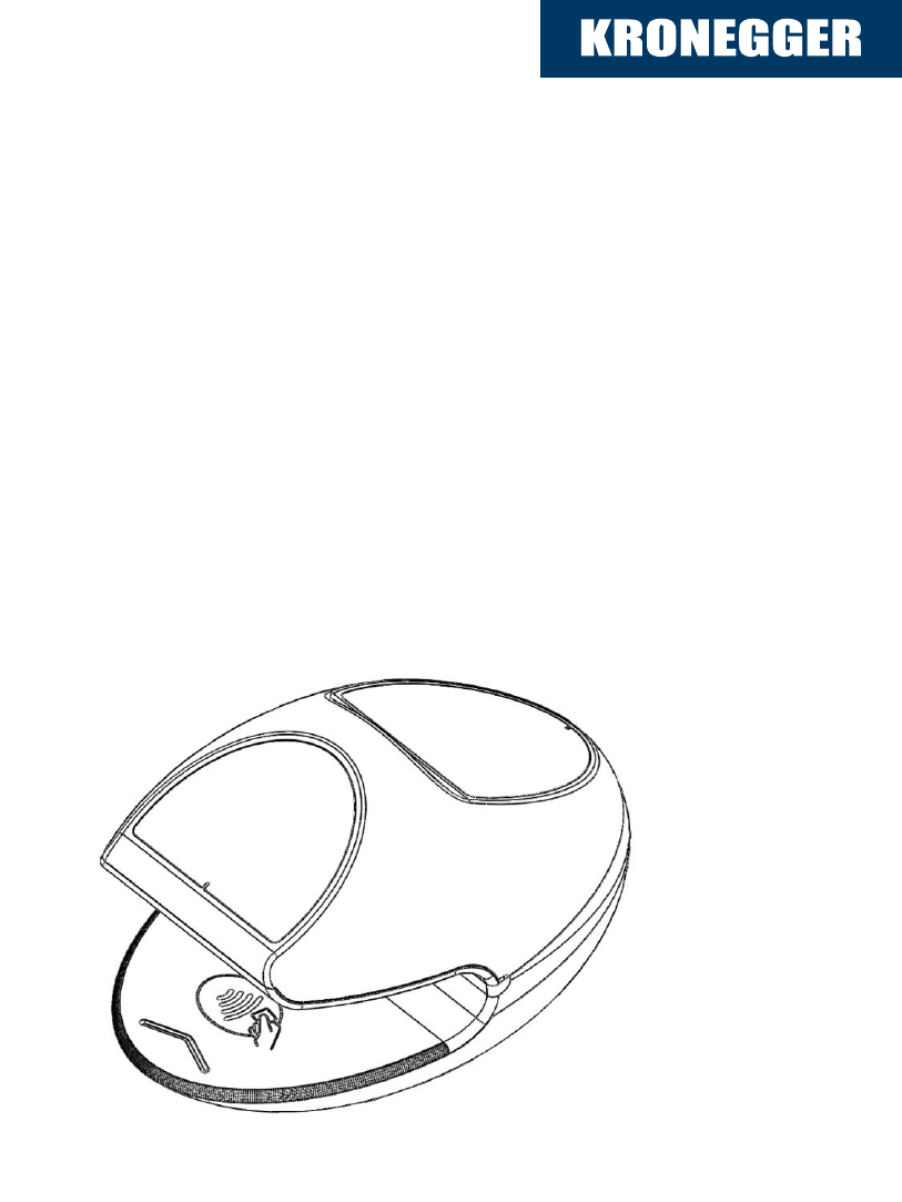
The EGG
Version 1.2
User - Manual

Documentation the EGG
18.06.13
Kronegger GmbH 2
Table of Contents
Table of Contents .................................................................................................... 2
1 Introduction ..................................................................................... 3
2 Getting Started ................................................................................ 5
3 Hardware ......................................................................................... 6
3.1 Features ....................................................................................................... 6
4 System Overview ............................................................................ 7
4.1 Block diagram............................................................................................... 7
5 Interface Overview .......................................................................... 8
5.1 Reader board ............................................................................................... 9
6 Functional Blocks ......................................................................... 11
7 Instruction Set ............................................................................... 12
Generic Commands – Overview ........................................................................... 12
8 Interface Details ............................................................................ 13

Documentation the EGG
18.06.13
Kronegger GmbH 3
1 Introduction
Kronegger GmbH. provides customer support and optional design in services for
properly integrating the products. Since we do not have full information on customer’s
applications or products, it is due to the customer to verify that the integrated
products are suitable for the application intended and that no patents or intellectual
property rights are infringed. Integrating the products into the customer’s application
is a development process that requires special experience, professional skills and
involves usual technical risks. Kronegger GmbH. assumes no responsibility or liability
for customer’s applications, their performance, the required development effort,
production, installation, operation, their suitability, reliability and safety. The products
are not designed for applications where malfunction could cause potential risk of
death, personal injury or environmental damage.
Any changes or modifications not expressly approved by the party responsible for
compliance could void the user's authority to operate the equipment.
This device complies with part 15 of the FCC rules. Operation is subject to the
following two conditions: (1) This device may not cause harmful interference, and (2)
This device must accept any interference received, including interference that may
cause undesired operation.
The manual has been written to the best of our knowledge. We do not guarantee the
correctness and completeness of the provided information and insist on the good
practice of crosschecking during the customer’s development process through
sufficient testing coverage. Feedback on errors in the manual are highly appreciated.
This document may be used to support the integration of Kronegger products. Any
other use, duplication, storage or circulation is not authorized shall be prosecuted as
a violation of copyright laws.

Documentation the EGG
18.06.13
Kronegger GmbH 4
FCC § 15.105
Note: This equipment has been tested and found to comply with the limits for a Class
B digital device, pursuant to part 15 of the FCC Rules. These limits are designed to
provide reasonable protection against harmful interference in a residential
installation. This equipment generates, uses and can radiate radio frequency energy
and, if not installed and used in accordance with the instructions, may cause harmful
interference to radio communications. However, there is no guarantee that
interference will not occur in a particular installation. If this equipment does cause
harmful interference to radio or television reception, which can be determined by
turning the equipment off and on, the user is encouraged to try to correct the
interference by one or more of the following measures:
—Reorient or relocate the receiving antenna.
—Increase the separation between the equipment and receiver.
—Connect the equipment into an outlet on a circuit different from that to which the
receiver is connected.
—Consult the dealer or an experienced radio/TV technician for help.
ICES-003
This Class B digital apparatus complies with Canadian ICES-003.
Cet appareil numérique de la classe B est conforme à la norme NMB-003 du
Canada.

Documentation the EGG
18.06.13
Kronegger GmbH 5
2 Getting Started
As factory default the data are transmitted at 115200, n, 8, 1 and no handshake. Two
protocol modes are available. As default the binary protocol is used. To change the
protocol type or the baud rate you have to configure the EEPROM (see EEPROM
Memory Organization).
For the communication with the reader you need the ReaderTool which is delivered
with any Kronegger Reader. The Microsoft .NET Framework 2.0 (or any higher
version) needs to be installed first in order to run the ReaderTool:
http://www.microsoft.com/downloads/details.aspx?familyid=0856EACB-4362-4B0D-
8EDD-AAB15C5E04F5&displaylang=en
The ReaderTool needs no installation, simply start it and the reader will be selected
automatically. Now you can communicate with your Mifare+ reader.
Step by Step:
Connect the Reader via the RS232 cable to the PC
Download and install the Microsoft .NET Framework
Start the ReaderTool
Now you can communicate with the reader
Documentation the EGG
18.06.13
Kronegger GmbH 6
3 Hardware
3.1 Features
Features Barcode and RFID-Reader
Dimensions 226.3mm (L) x 152.9mm(W) x 124.6mm(H),
Interface type RS232
Power supply 12 VDC ±10% regulated
Documentation the EGG
18.06.13
Kronegger GmbH 7
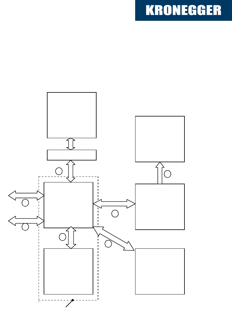
4 System Overview
4.1 Block diagram
Barcode-
Reader
Controller-
Board
Operator
Display
Display
Board
To Host
Readerboard
Reset
Deco LED´s
1
2
3
6
7
8
9
DD
on the same pcb
Adapter PCB
Documentation the EGG
18.06.13
Kronegger GmbH 8
5 Interface Overview
Number
Connection
1
Interface for power-supply, RS232
2
Interface for display´s, optic and acoustic signals
3
Interface for barcode-reader
6
Interface for operator display
7
Interface for deco LEDs
8
Reset button
9
Interface to reader board (Controller Board and Reader
Board is one pcb)
Documentation the EGG
18.06.13
Kronegger GmbH 9
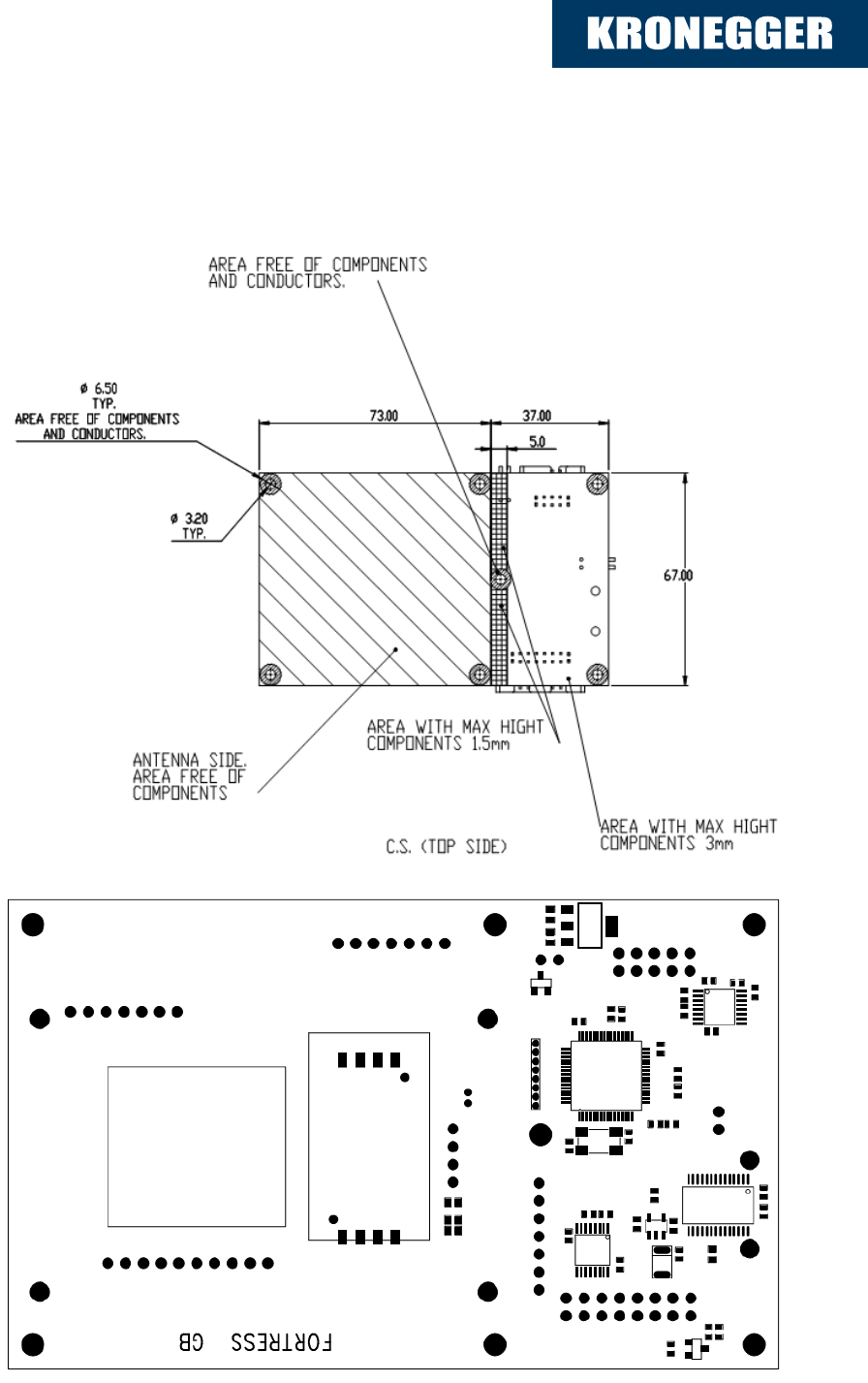
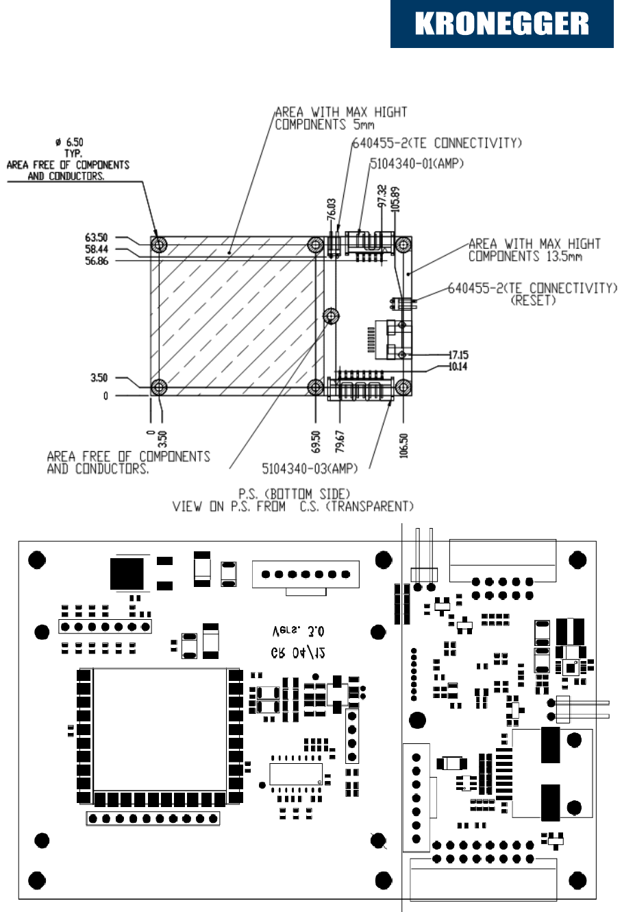
5.1 Reader board
Top view (Antenna side): EGGR-2012-01(READER PCB ASSY)-REV.C.DXF
TOP side: SAM holder and LEDs are not populated on Reader board
Documentation the EGG
18.06.13
Kronegger GmbH 10
Bottom view: EGGR-2012-01(READER PCB ASSY)-REV.C.DXF
View on Bottom Side from Top (Transparent)

Documentation the EGG
18.06.13
Kronegger GmbH 11
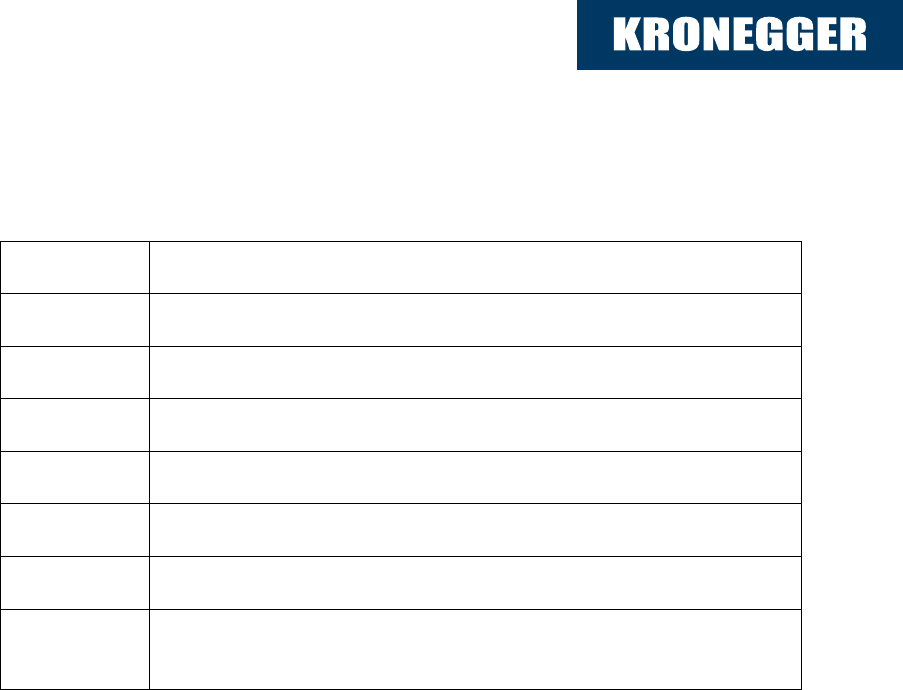
6 Functional Blocks
Module
Description
Barcode Reader
Unit to read barcodes and to transmit the information via serial TTL signals
(standard) or RS232 signal (optional) to the main-controller
Barcode-Reader Type Symbol PL3307 or PL4407 via barcode
interface
Barcode reader is connected via connectors-converting adapter PCB
Operator Display
Module to visualize information in a 4 lines x 20 characters display
NHD-0420D3Z-NSW-BBW
Controller Board
Controller board who handles the internal signals and the communication
with the host
CPU STM32F103
RS232 Interface
Deco LED driver interface
User display connector with: User display Operator display, 4 LED (à
3V/75 mA), Illumination LED (5V / 150mA), Buzzer (3,3V / 100mA)
12 V to 5 V Power-supply with switched regulator 1500 mA for own
supply: 5V/600mA for display board: 5V/900mA
Reset (power interruption): by Software (standard), Hardware
(optional) with pin header via FET
Display Board
Sub-module to the controller board with a user display to show specified user
information and handles specific signals
User display NHD-0216K3Z-FL-GGW
LED´s single switched
illumination LED
Buzzer
Connector Operator display
Reader Board
(combined with
EGG Controller-
Board)
13,56 MHz RFID reader with integrated antenna to read most of the usual
tags
Modified Module “Fortress GB” version 1.0 (GR12/11) No RS232
Interface instead TTL signals
No Connector (direct connected to EGG controller board via 0R
resistors)
RS232 Interface optional
Deco LED
5 Deco-LED´s supplied from 12V; switched
Documentation the EGG
18.06.13
Kronegger GmbH 12
7 Instruction Set
Following table describes all commands of the reader device. Each command sends
a response to the host. Exceptions are mentioned explicitly. The green LED is
acknowledging a successfully executed command. The red LED indicates an error.
Generic Commands – Overview
Command
Description
'v'
Get Version
‘d’
Sleep mode
'x'
Reset
'bg'
Get data from barcode scanner and reader
'bc'
Route command directly from Host to barcode scanner
'bs'
Change the Baudrate of the Barcode Reader connection
‘bp’
Set continuous mode of barcode camera
'rc'
Route command directly from Host to reader
'rs'
Define Uart settings of RFID-Reader
‘rp’
Start polling mode for RFID-Redaer
‘el’
Enable/Disable EMV LED´s individually
'il'
Control illumination LED
'le'
Control deco LED´s
'ud'
Send command to user display
‘od’
Send command to operator display
'be'
Enable/Disable buzzer
'bf'
Set buzzer frequency and duty cycle
Documentation the EGG
18.06.13
Kronegger GmbH 13
'sn'
Get Serial number of ARM-Controler
'gl'
Get latency Time of the peripherals
'td'
Test device peripherals against preset values
'gt'
Get Temperature of ARM-Controler
'gv'
Get voltages of 3,3V 5V and 12V ADC´s
'tc'
Test all IO´s of the peripheral switch board
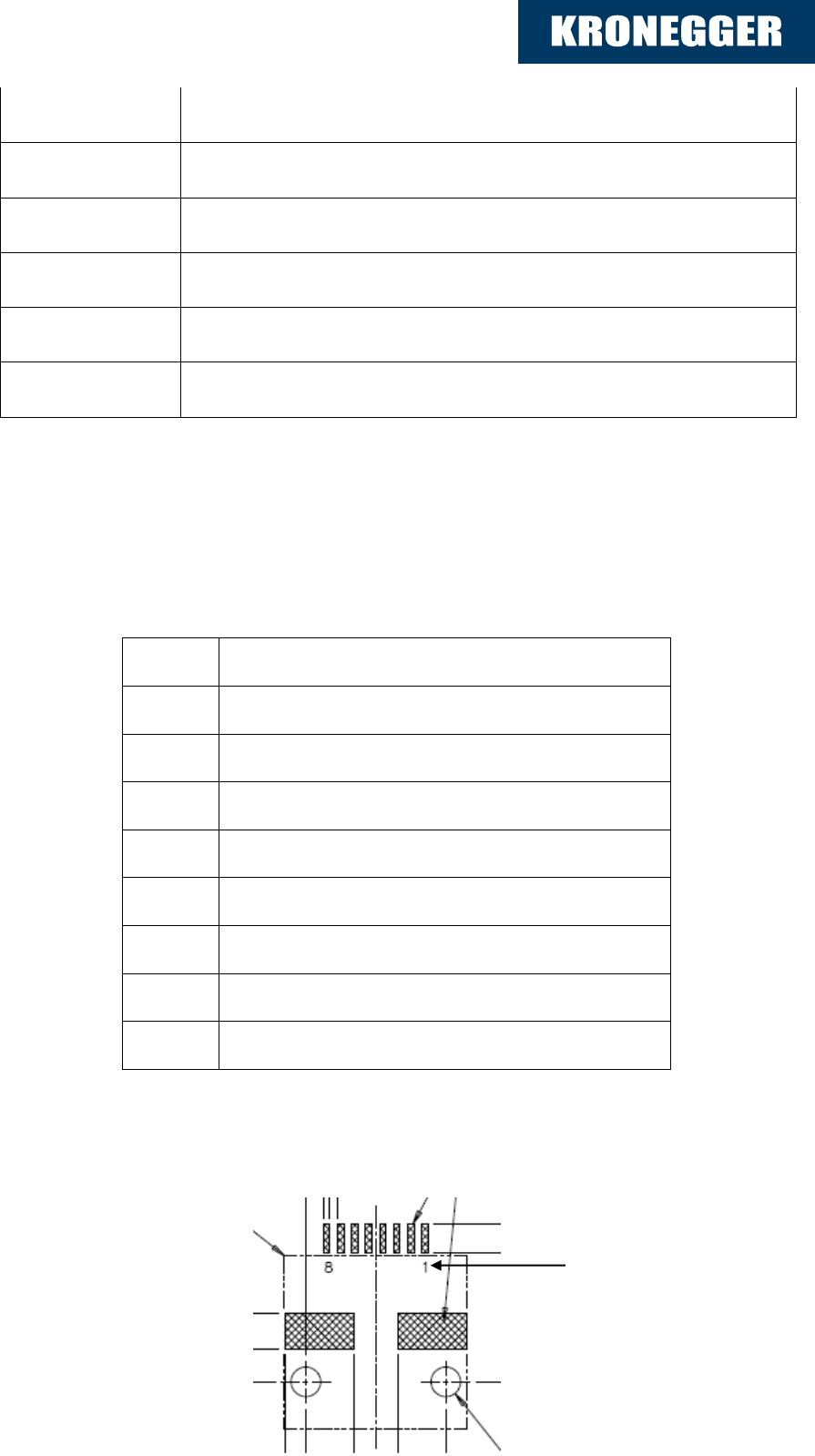
8 Interface Details
Controller Board to Host (1): Connector RJ45-8P/8C
Connector RJSS-5080 Amphenol Canada Corp.
Pin Nr
Connection
1
GND
2
Reserved for future use
3
Reserved for future use
4
RS232 Rx
5
GND
6
VCC (+12 V)
7
RS232 Tx
8
Vcc +12 V
Pin Nr.
Documentation the EGG
18.06.13
Kronegger GmbH 14
Version History
Date
Revision Number
18.03.2013
Version 1.0
15.04.2013
Version 1.1
18.06.2013
Version 1.2