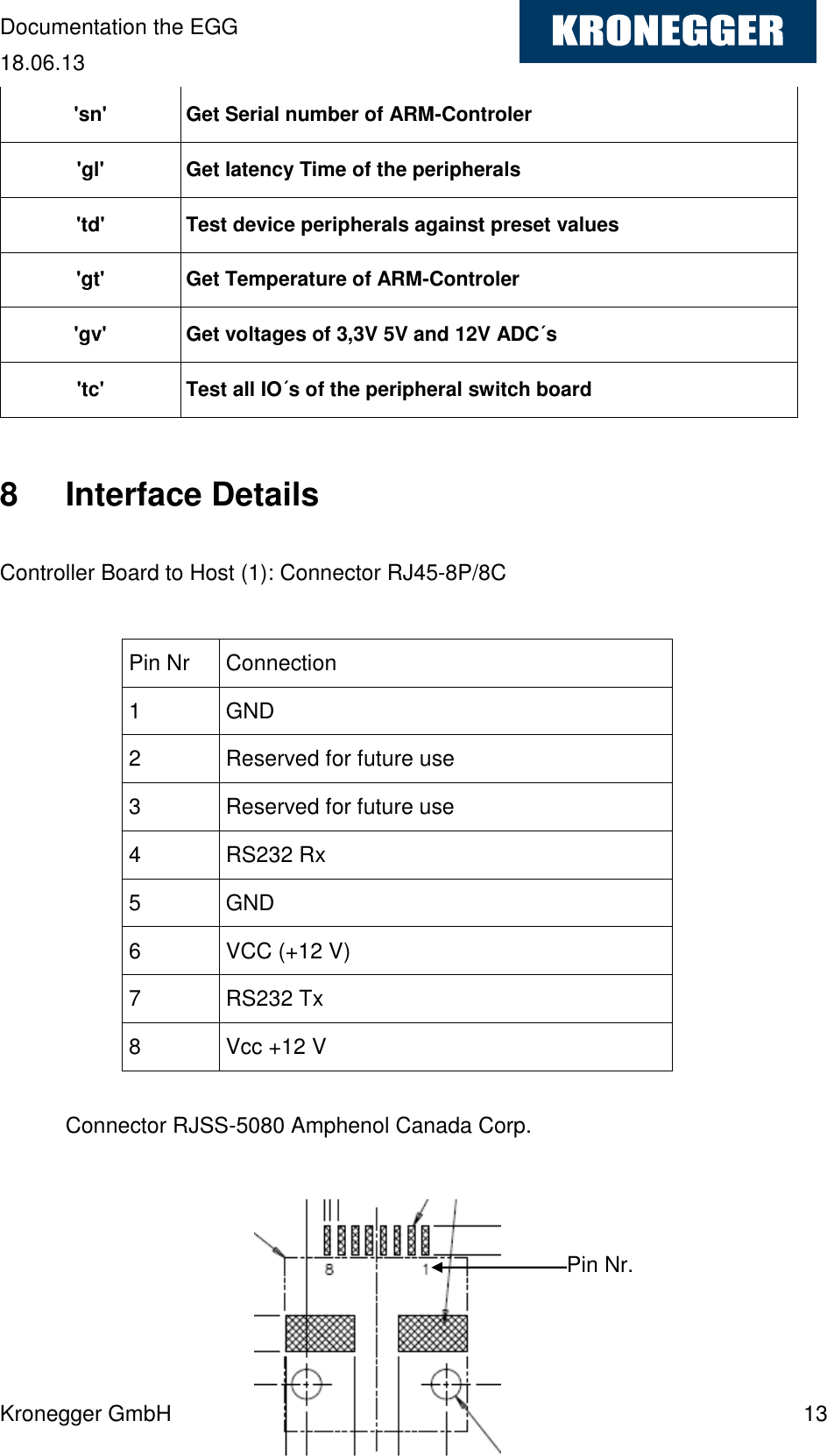
Kronegger FORT-9912-5018 RFID Reader User Manual
Kronegger GmbH RFID Reader
UserManual.wiki
>
Kronegger
>
FORT 9912 5018 User Manual
user manual
Navigation menu
Upload a User Manual
Namespaces
Wiki Guide
HTML
PDF
Info
Views
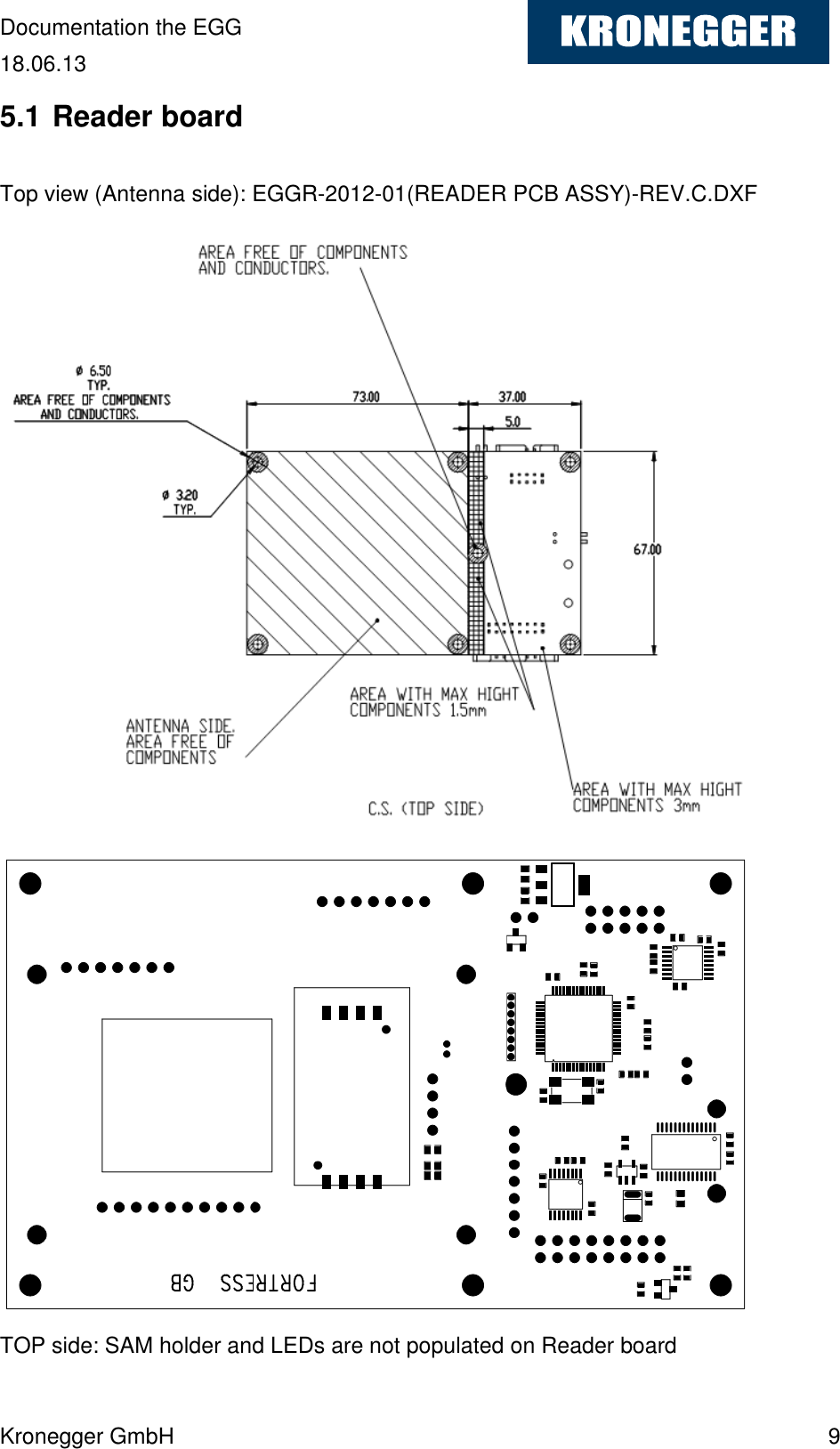
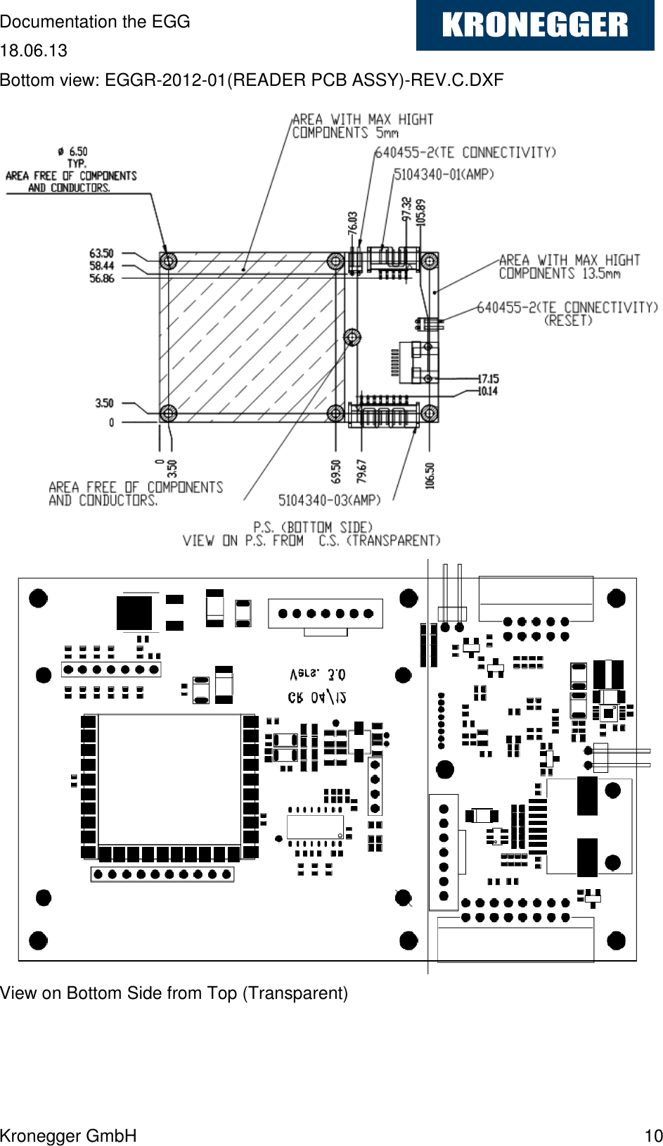
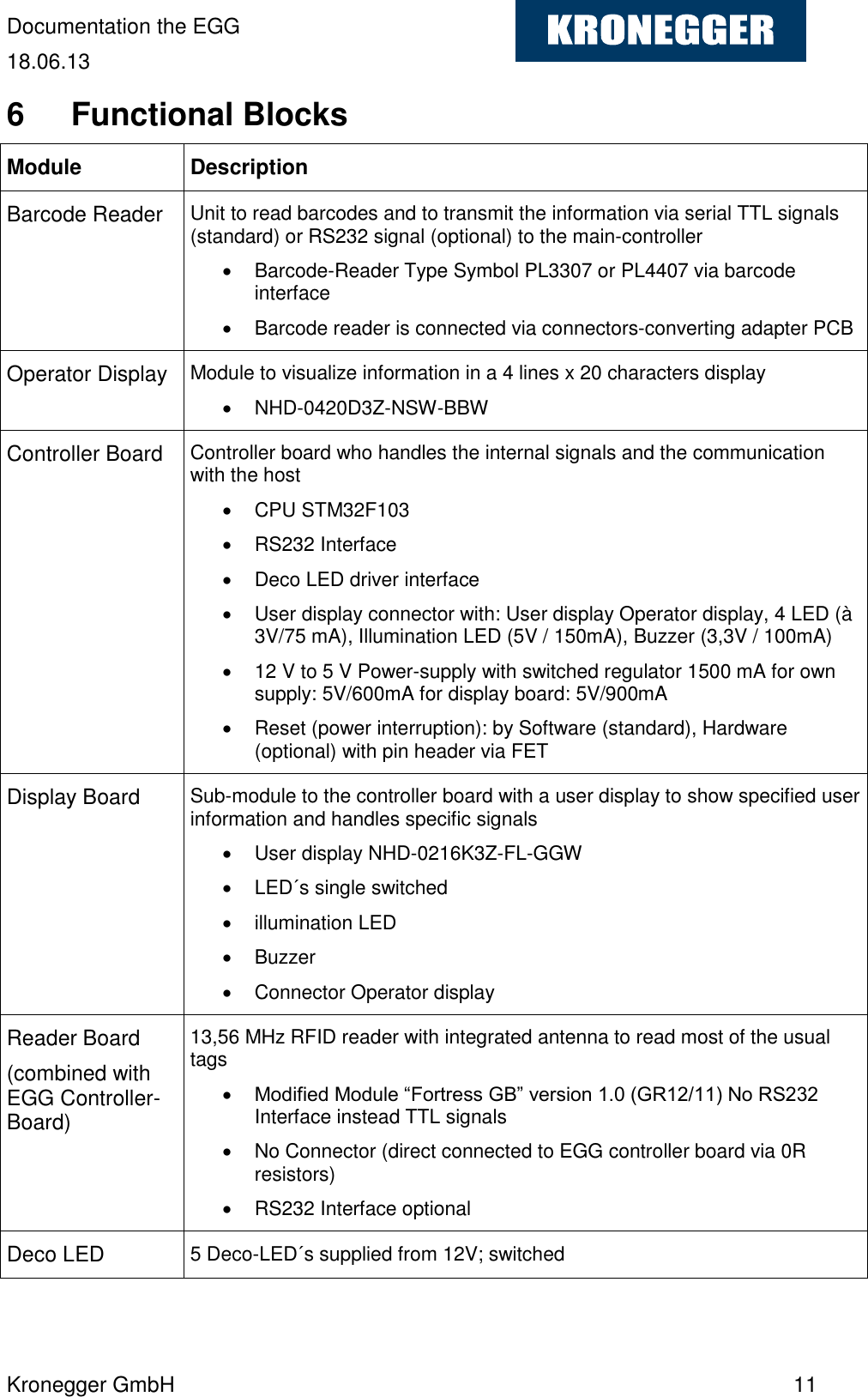
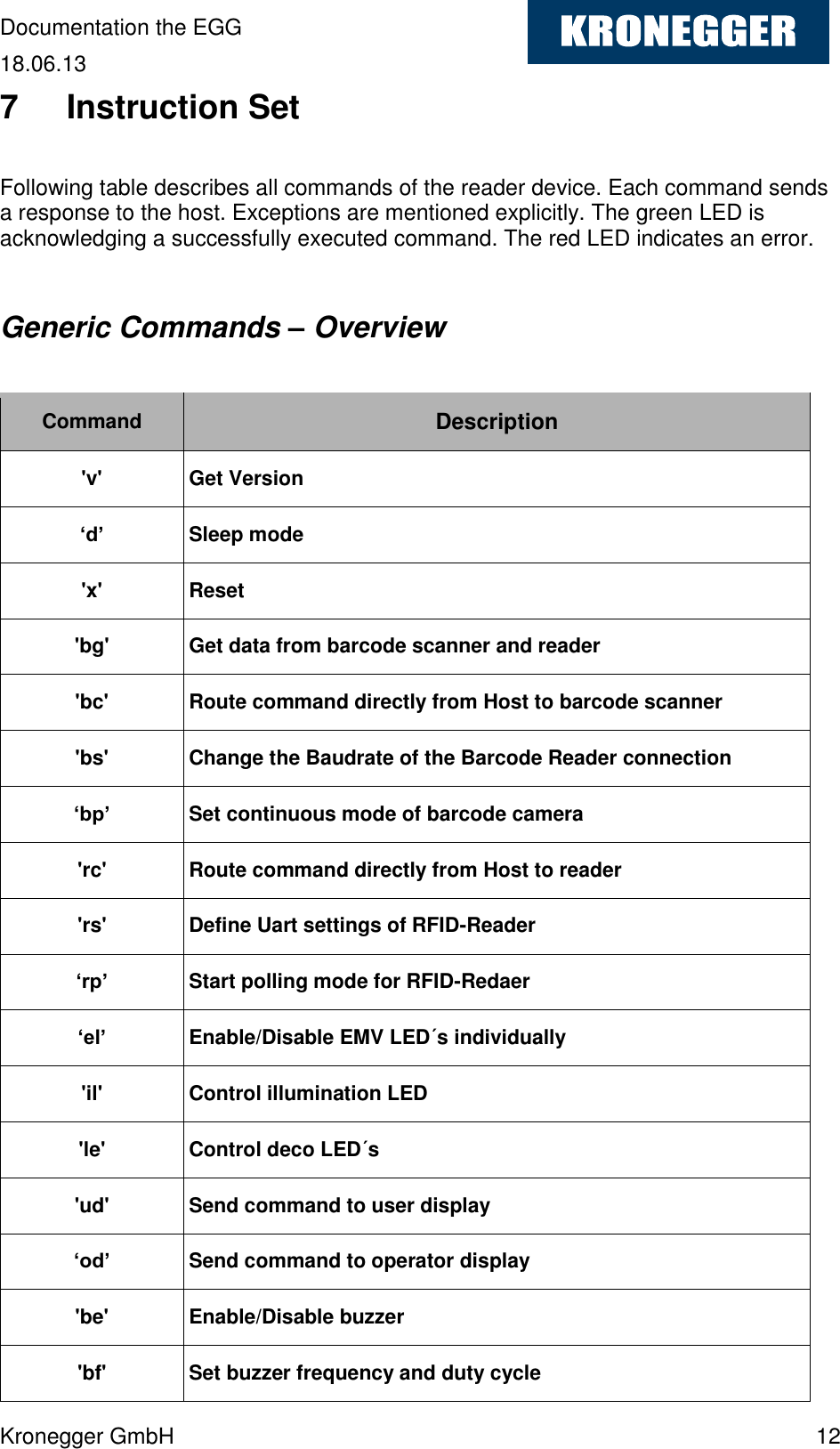
User Manual
Discussion / Help
Navigation