Kronegger PP-0403-3003 RFID Module User Manual
Kronegger GmbH RFID Module
UserManual.wiki
>
Kronegger
>
PP 0403 3003 User Manual
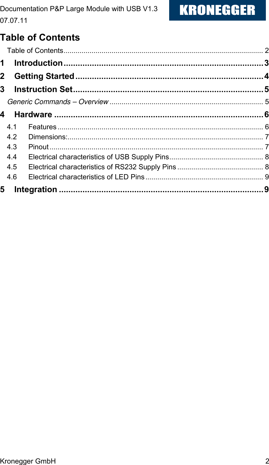
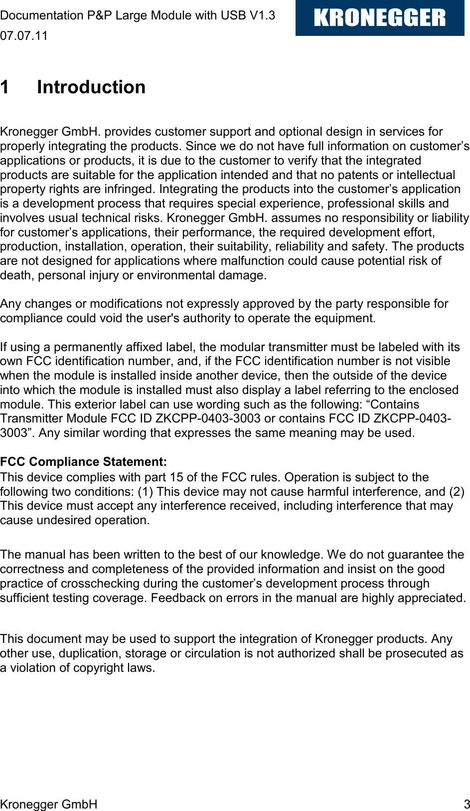
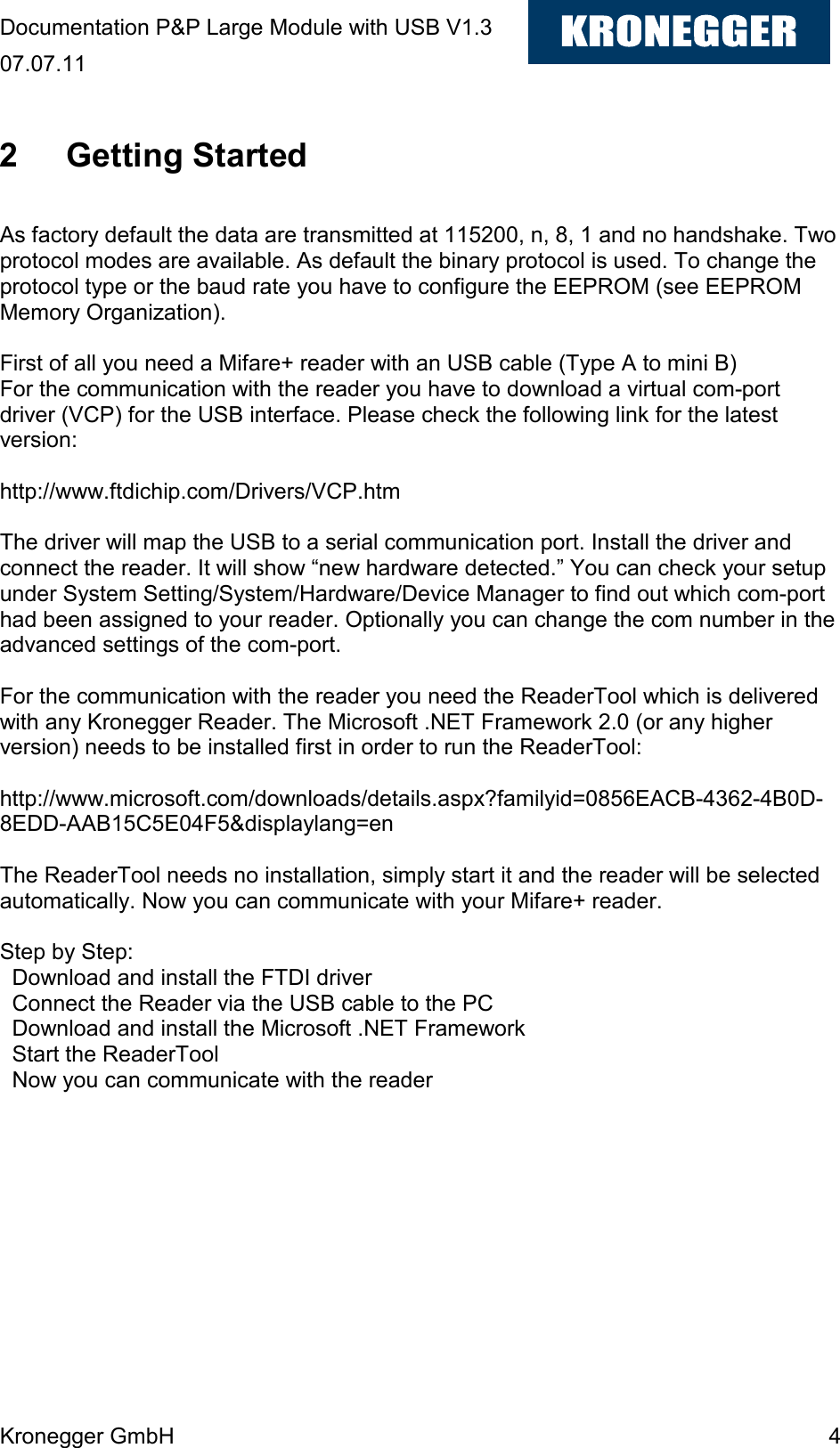
User Manual
Navigation menu
Upload a User Manual
Namespaces
Wiki Guide
HTML
PDF
Info
Views
User Manual
Discussion / Help
Navigation