Kronos 8609K003 RFID READER HID 125 KHz; INTOUCH DATA COLLECTION DEVICE User Manual Kronos InTouch Installation Guide
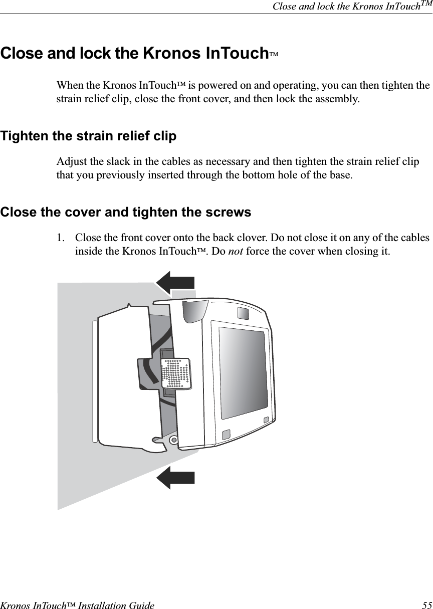
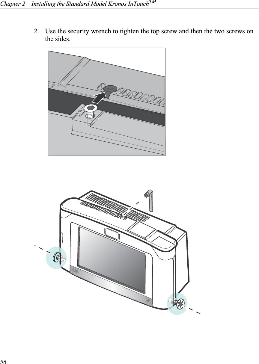
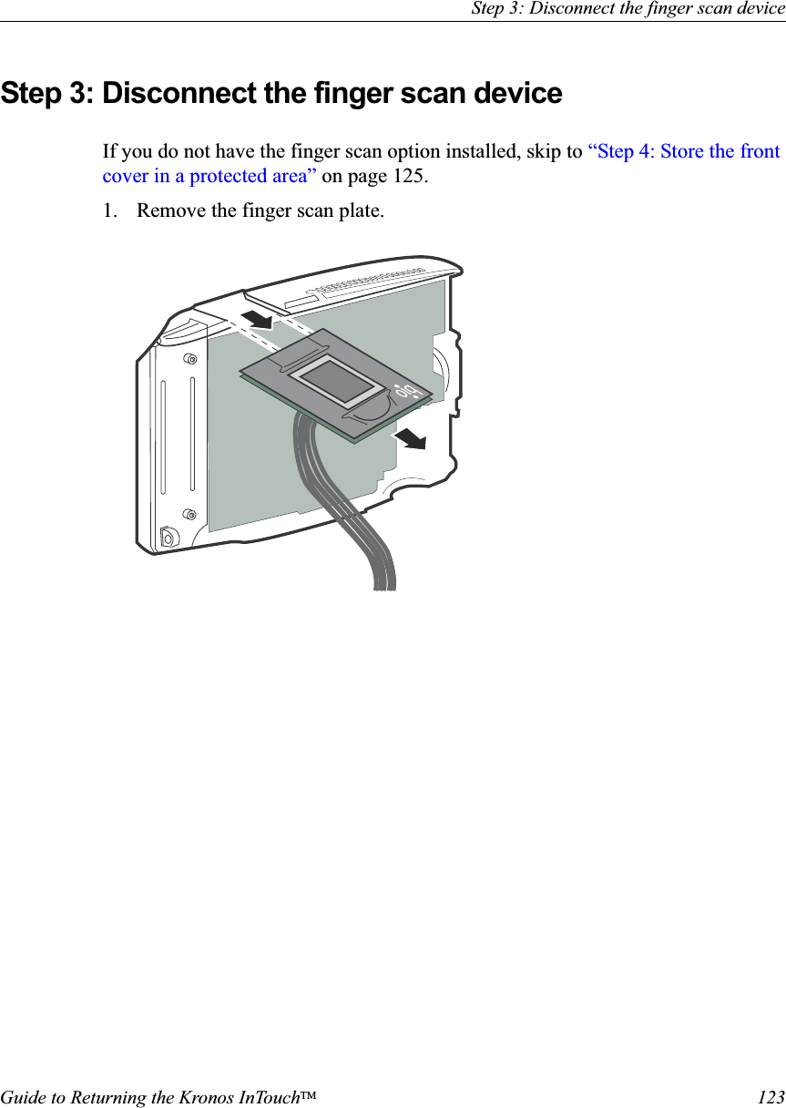
Kronos, Inc. RFID READER HID 125 KHz; INTOUCH DATA COLLECTION DEVICE Kronos InTouch Installation Guide
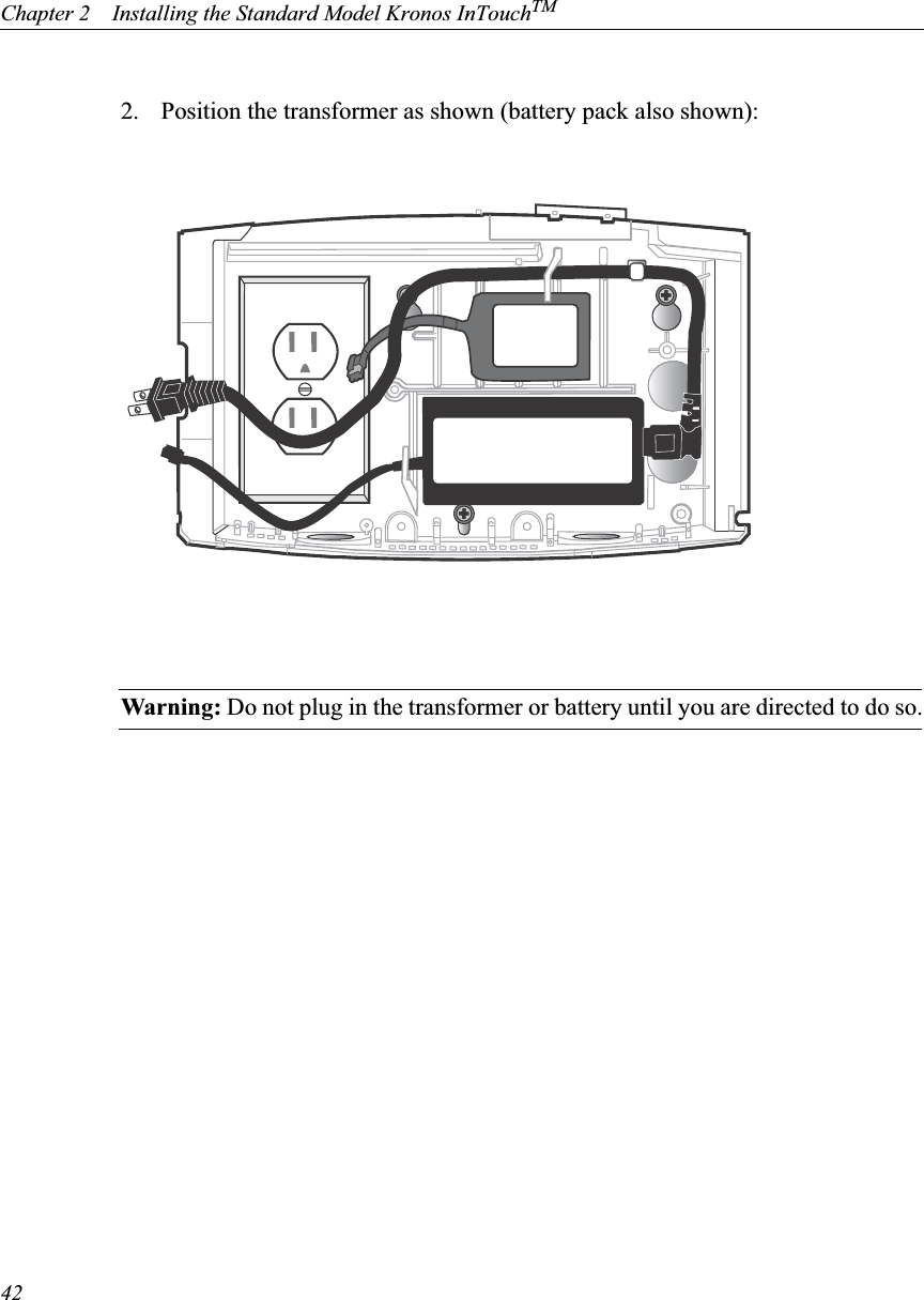
Kronos >
Users Manual

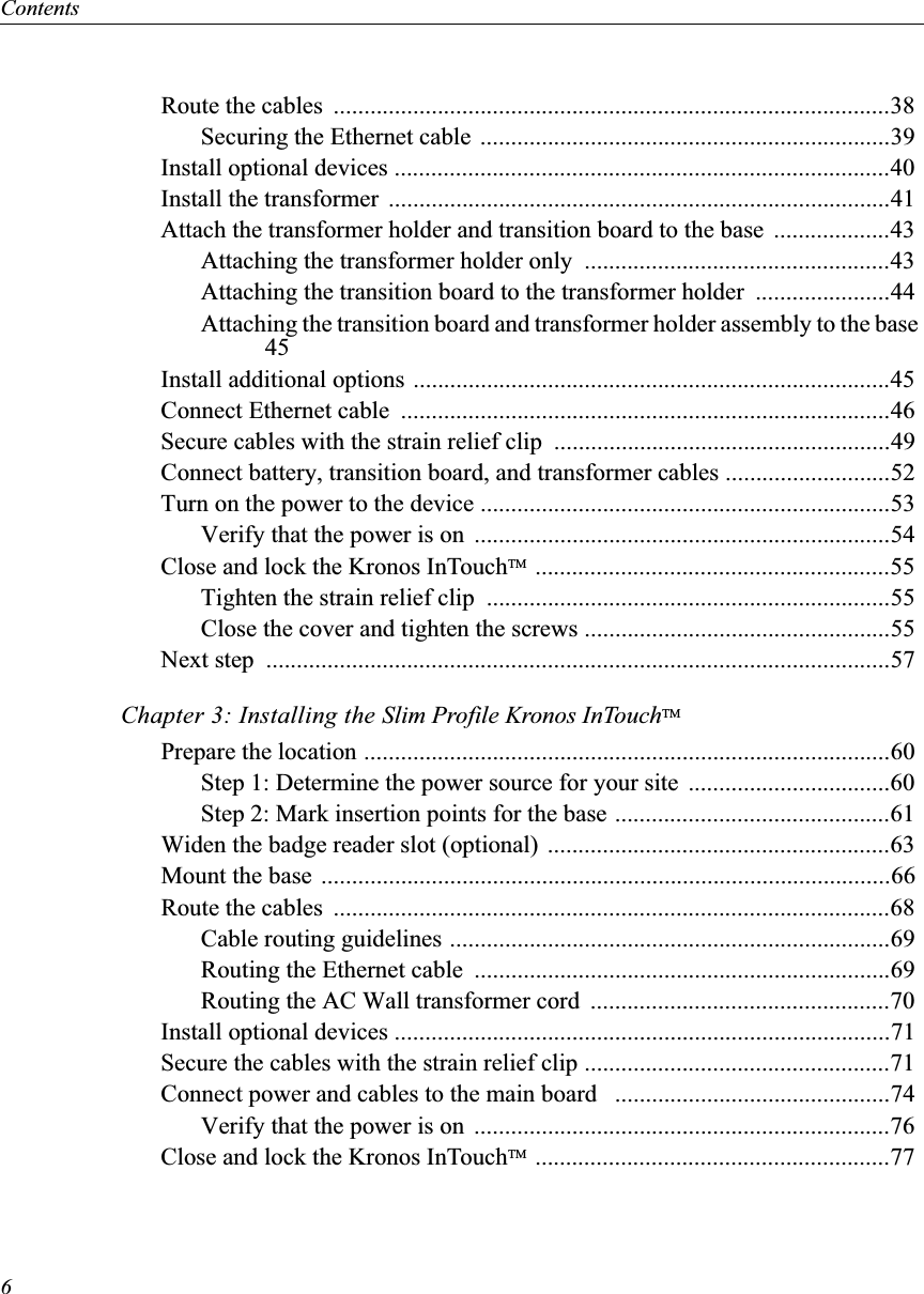

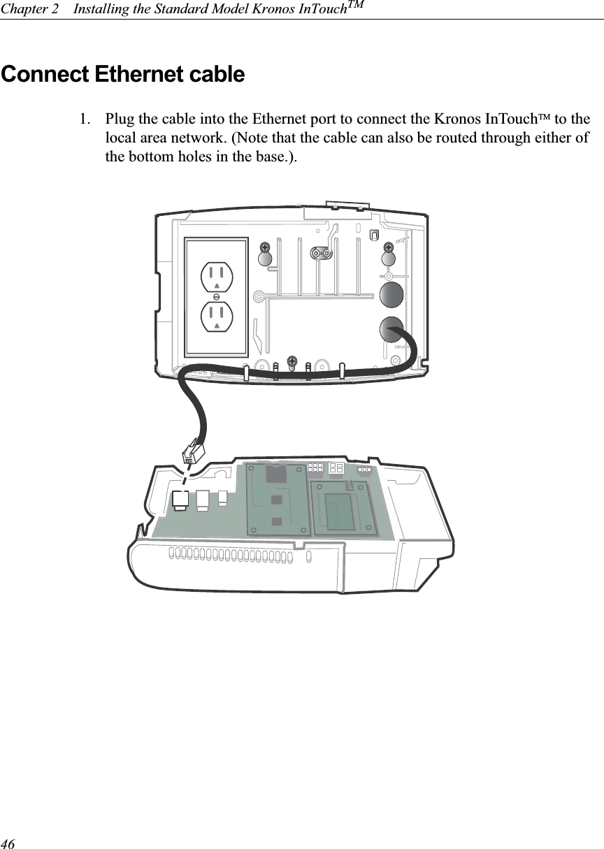
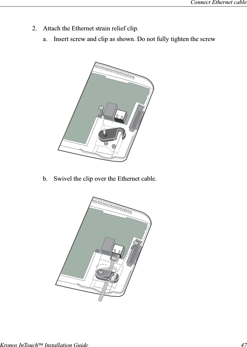
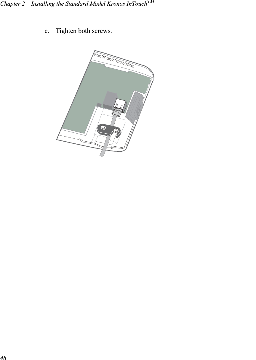
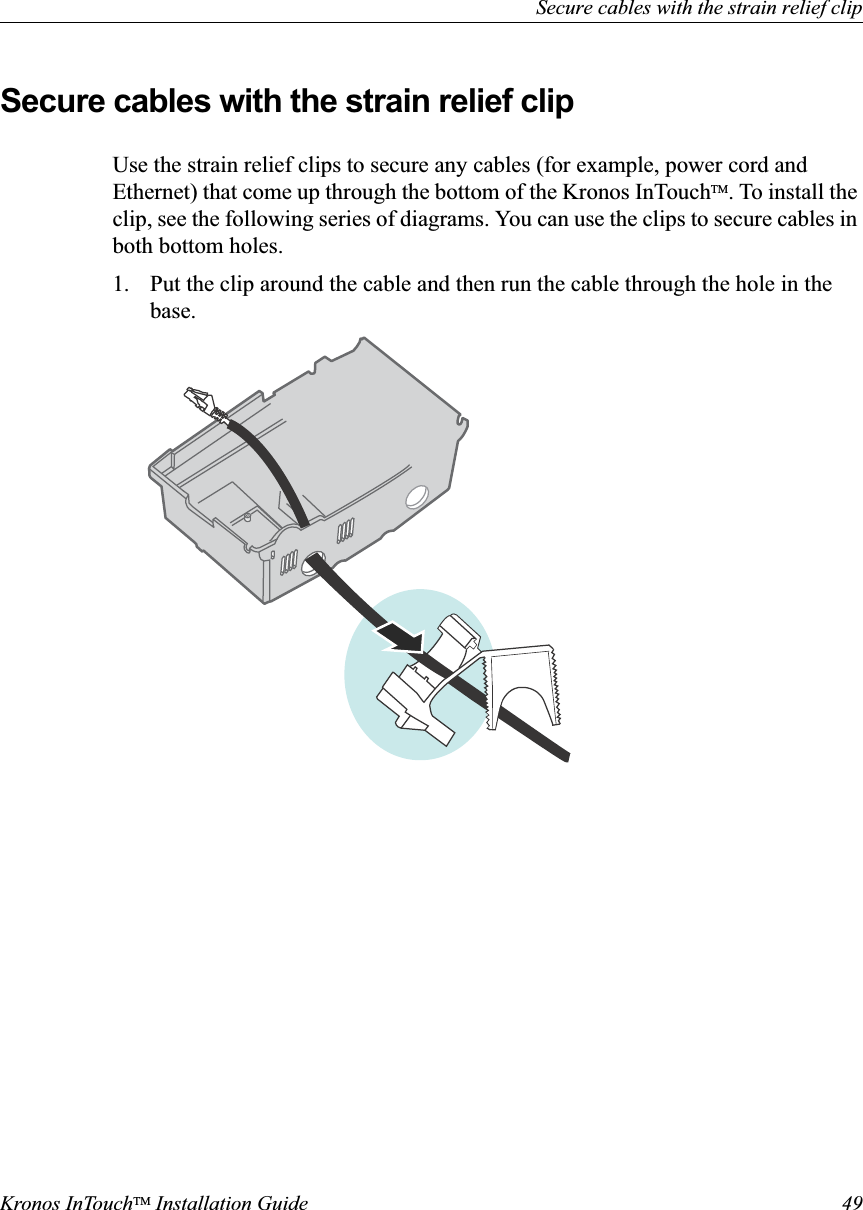
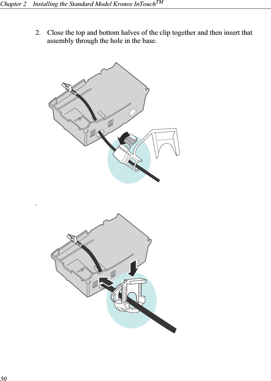
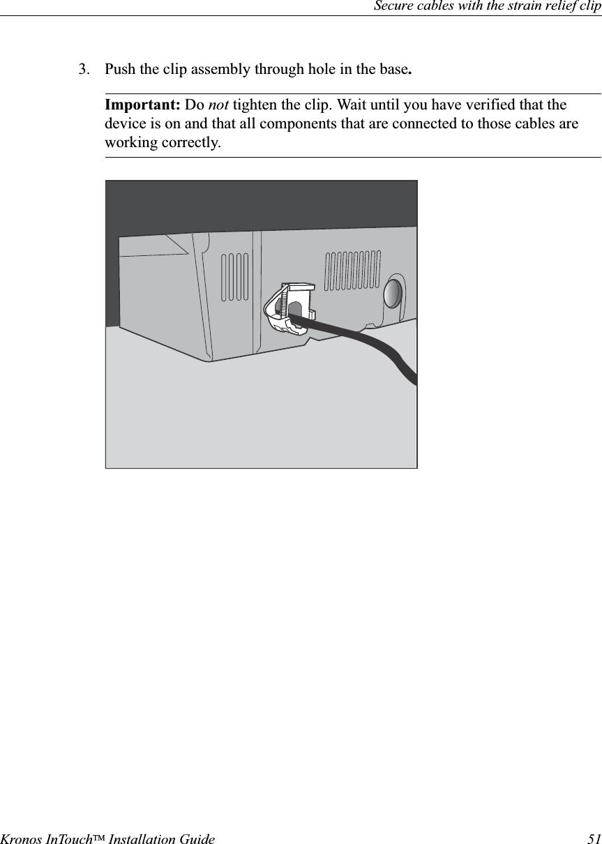
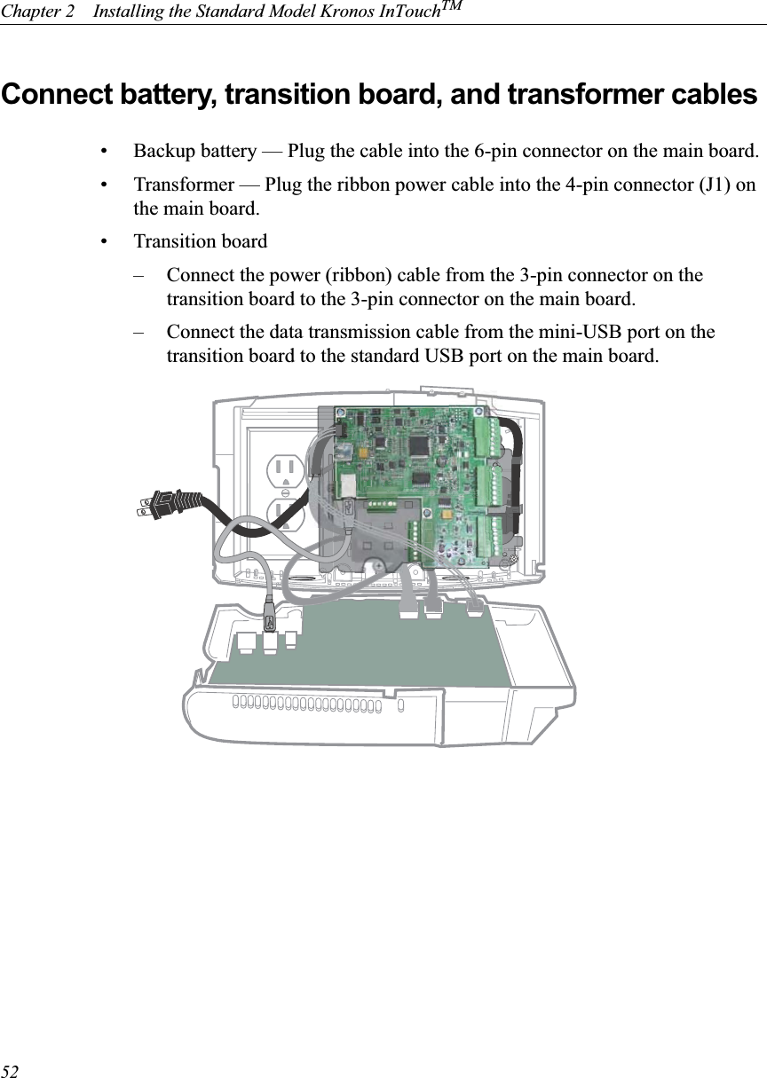
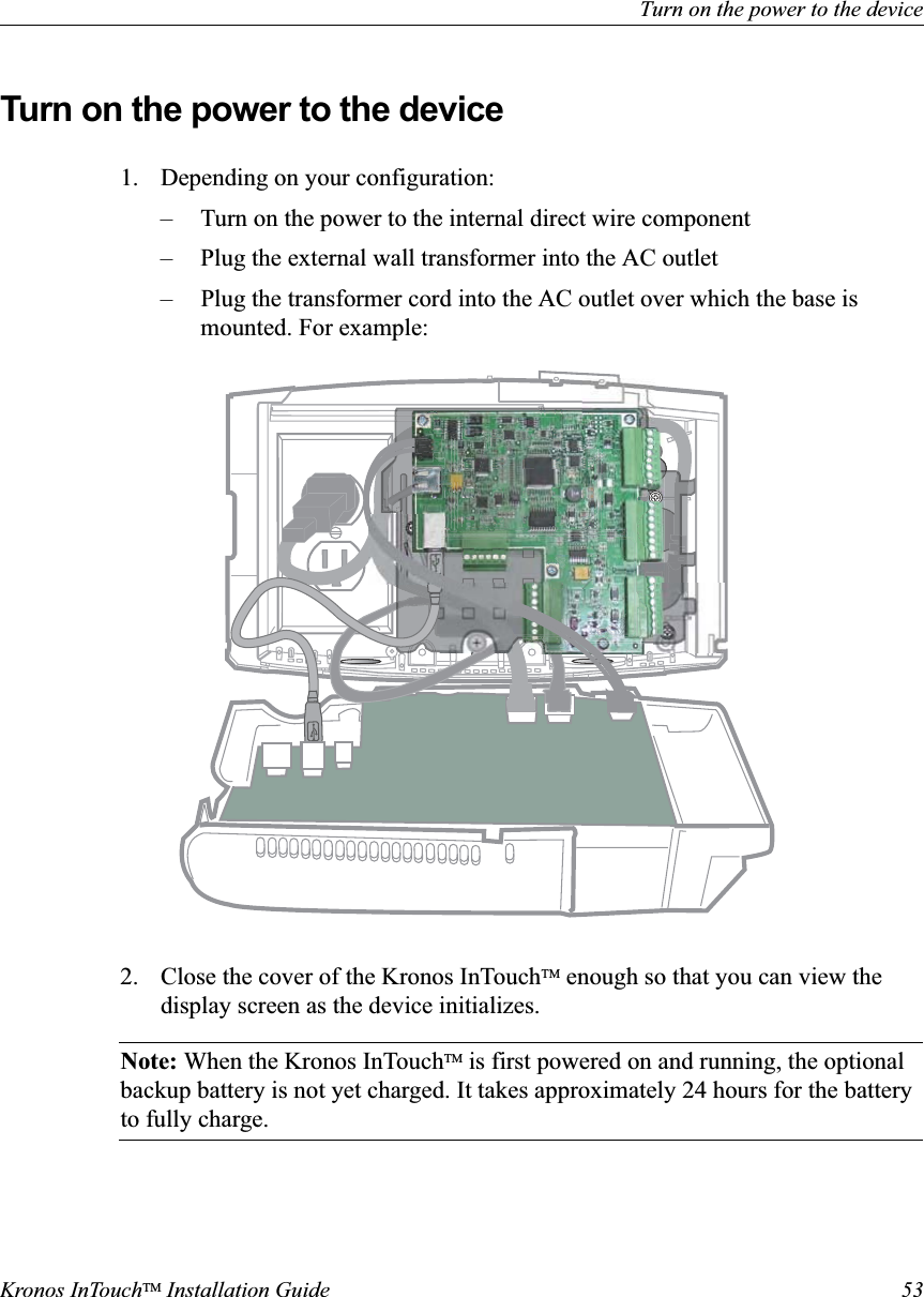
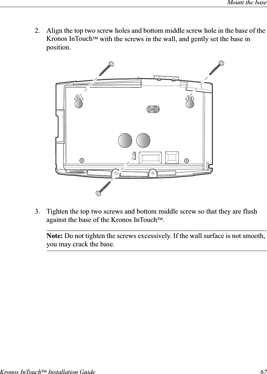
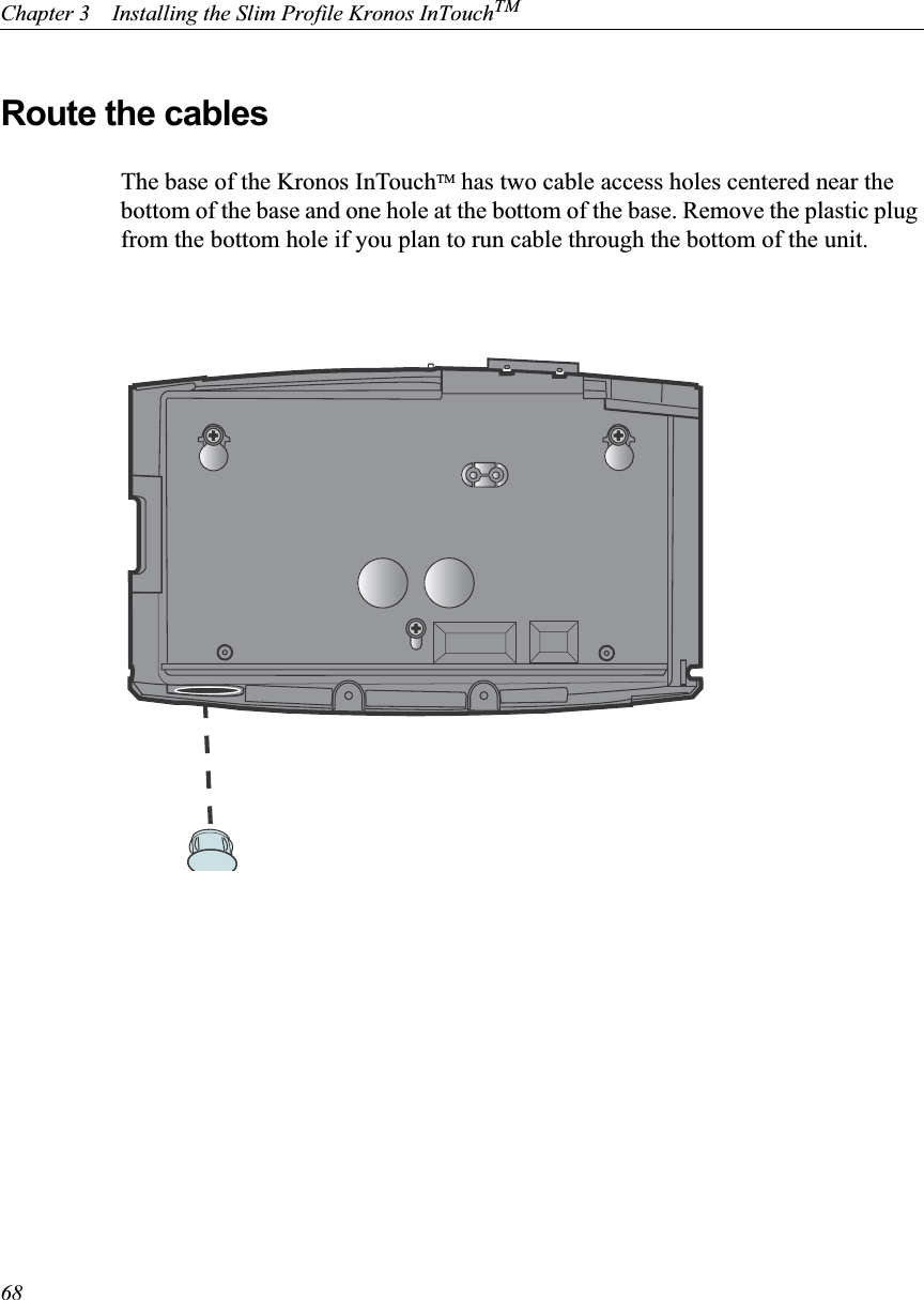
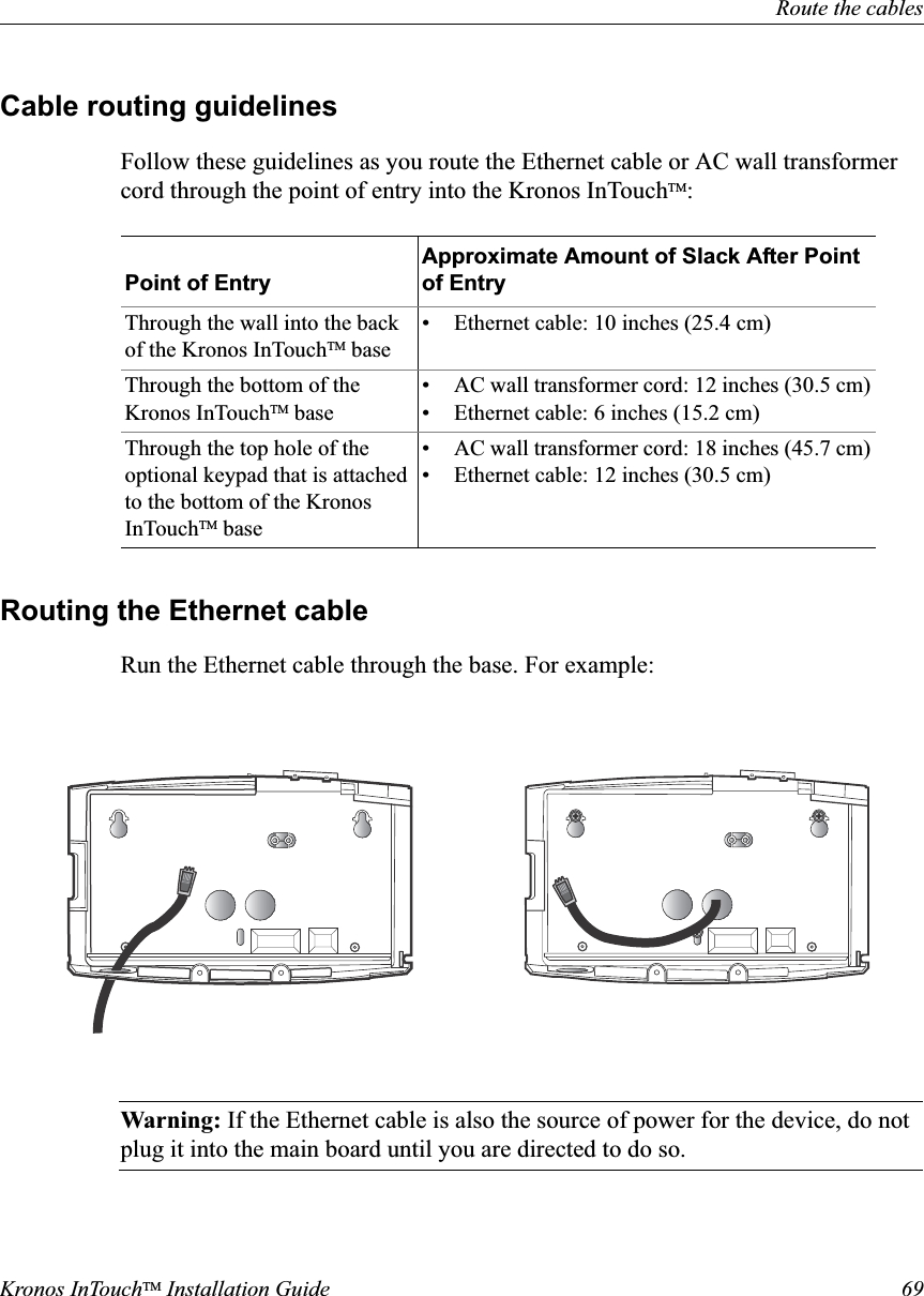
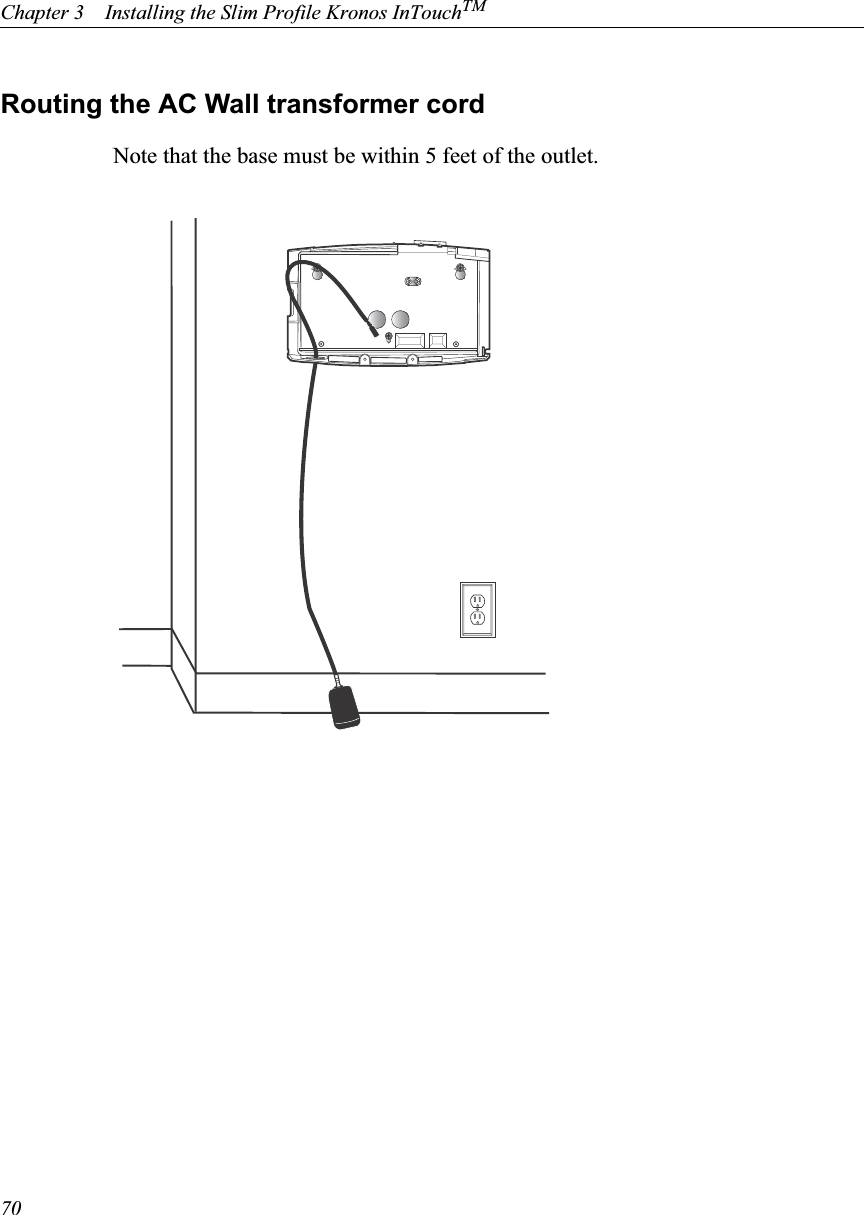
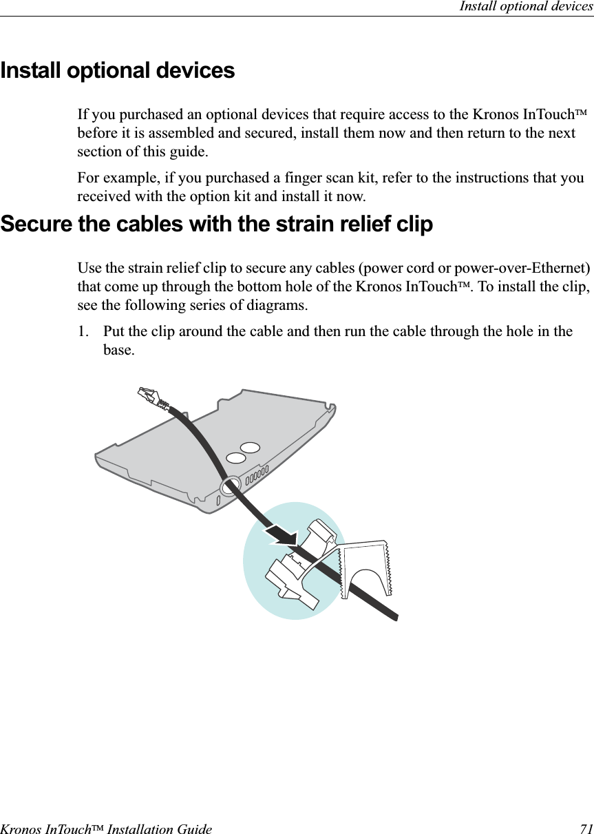
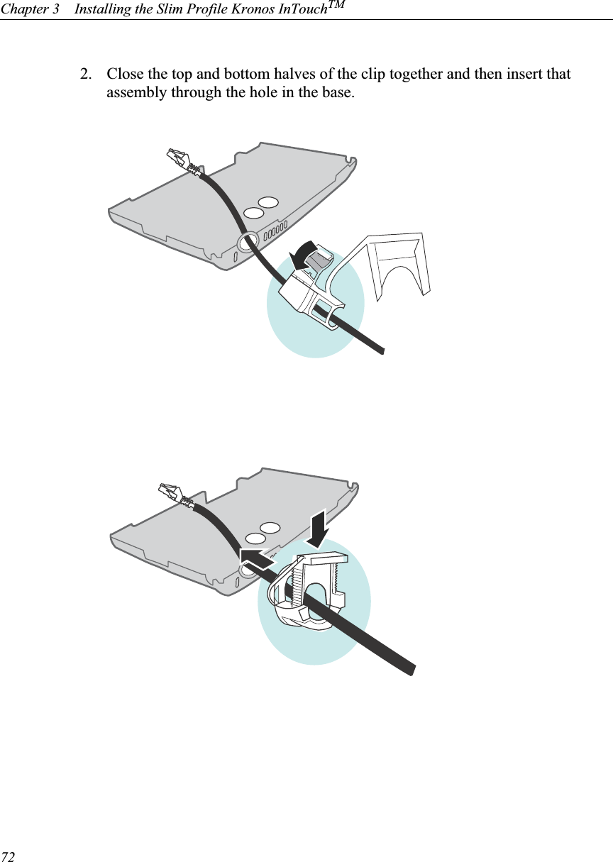
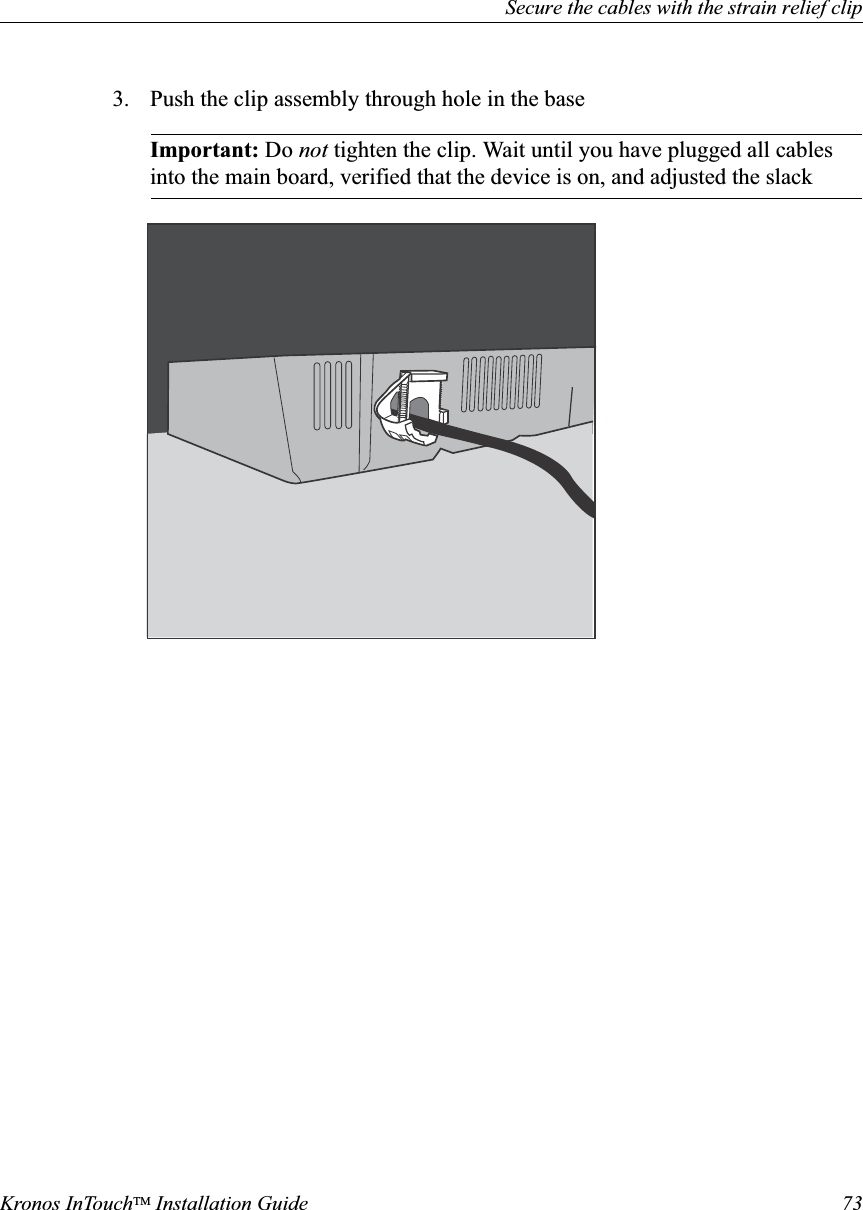
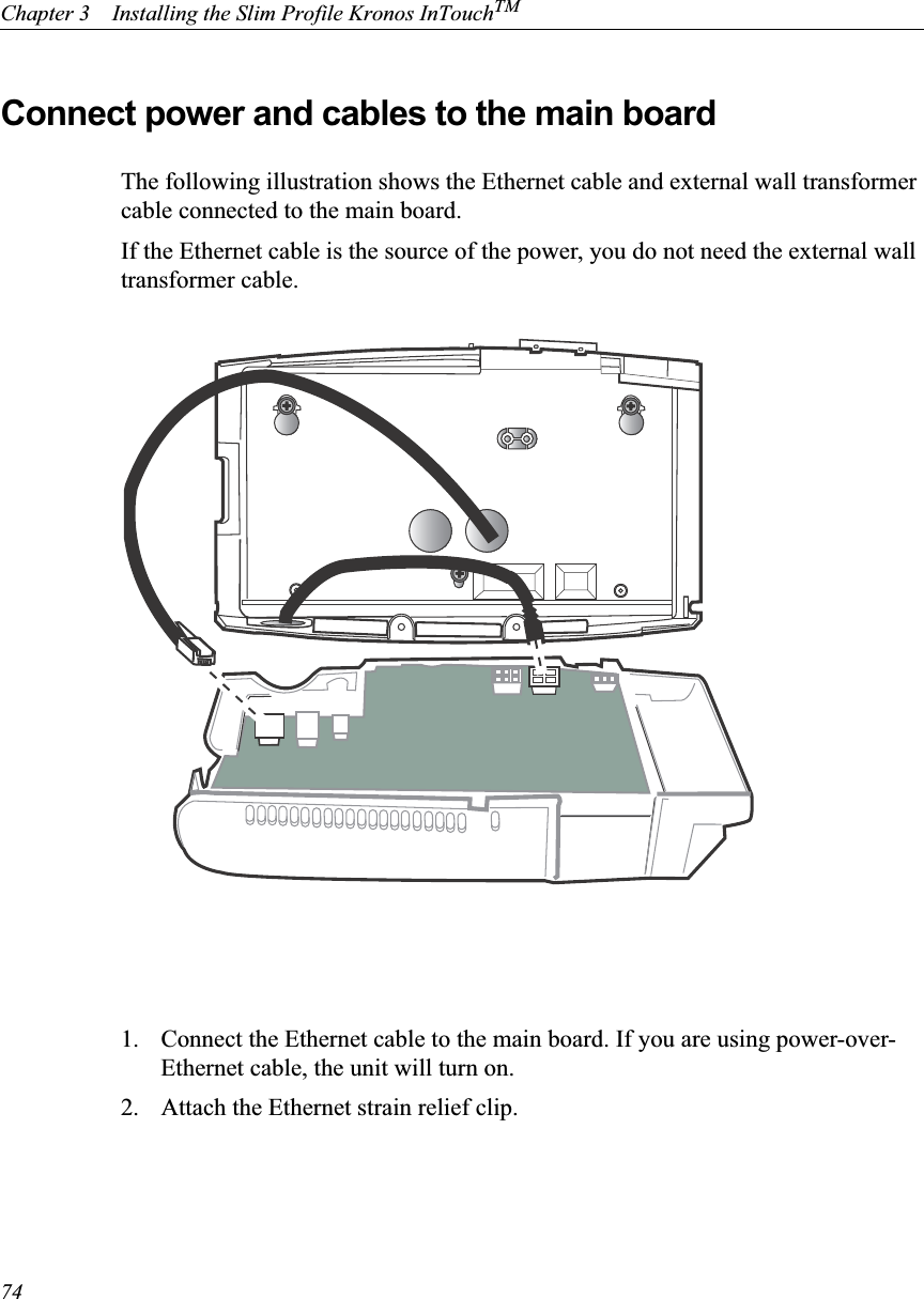
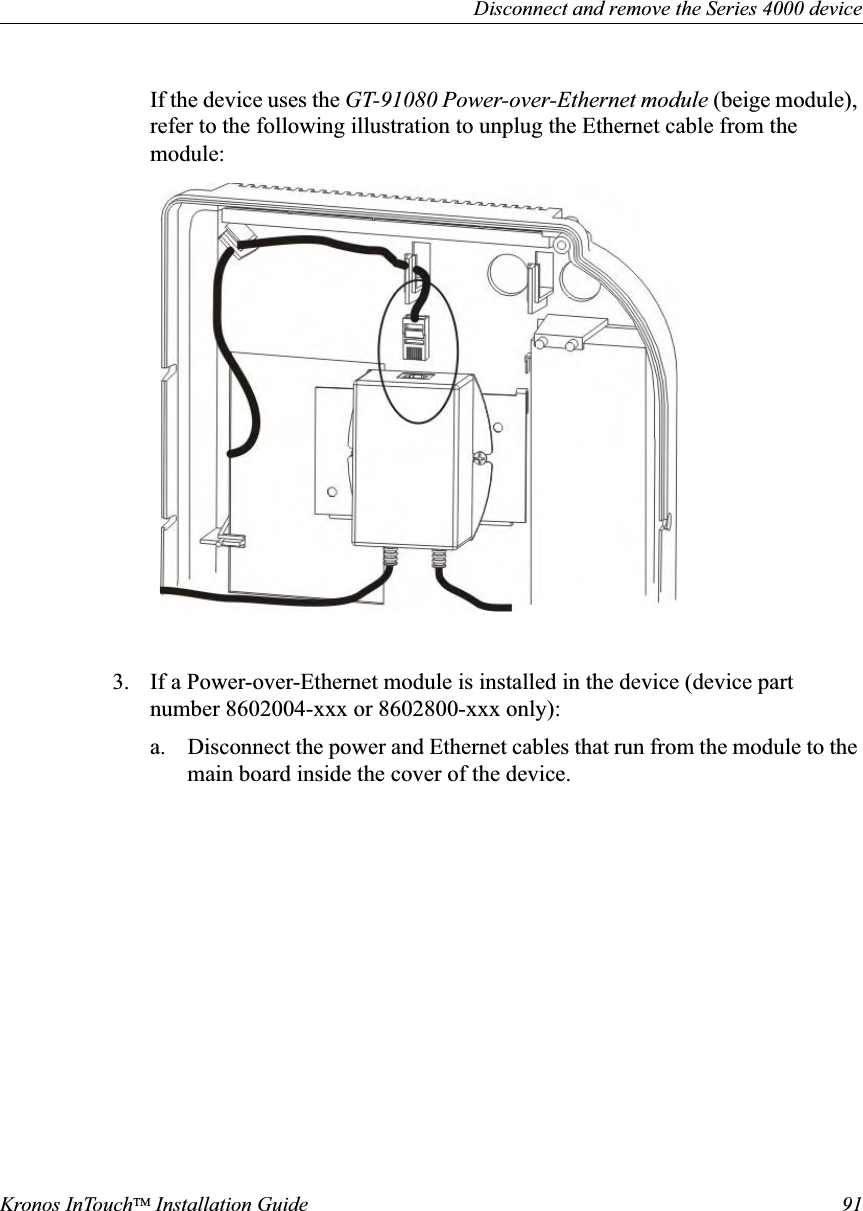
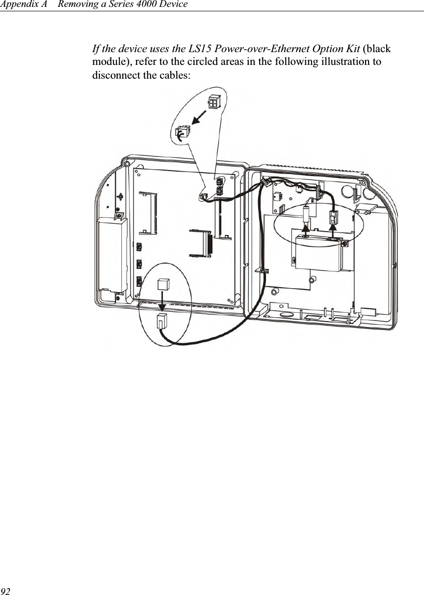
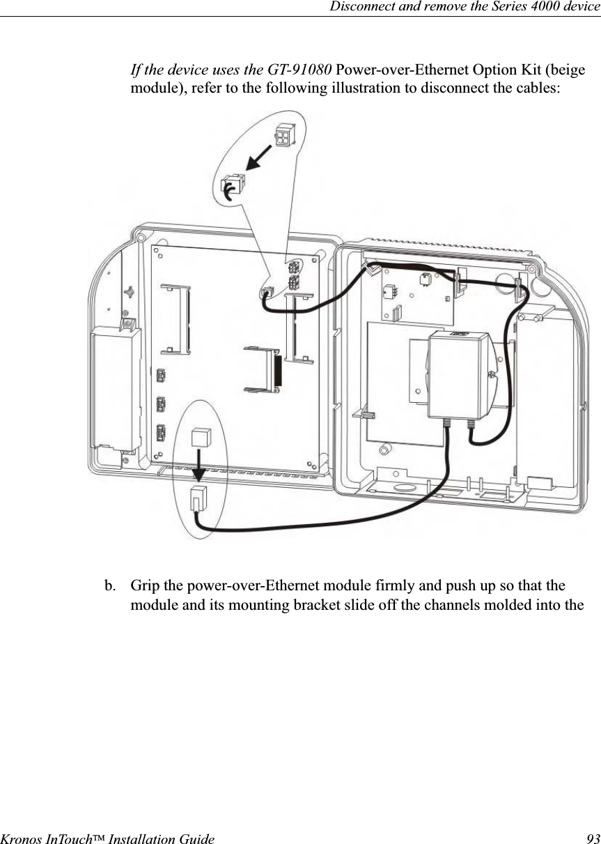
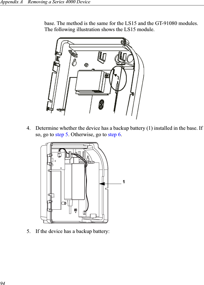
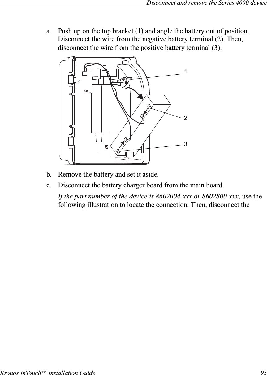
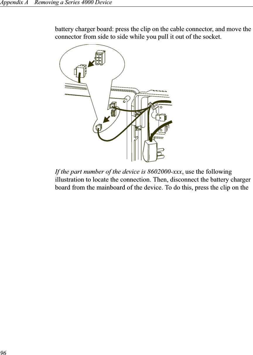
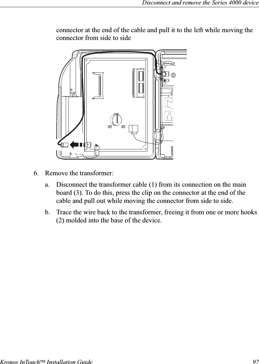
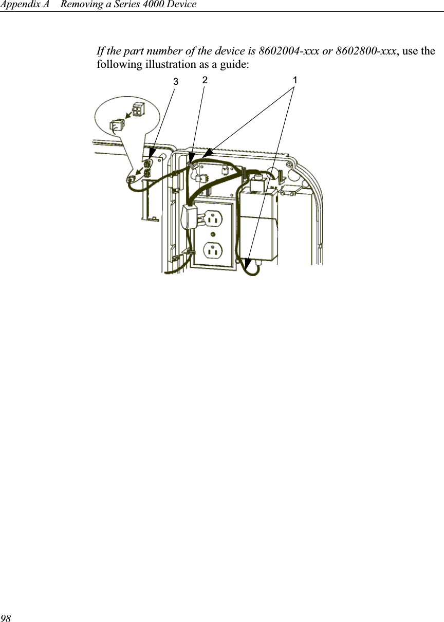
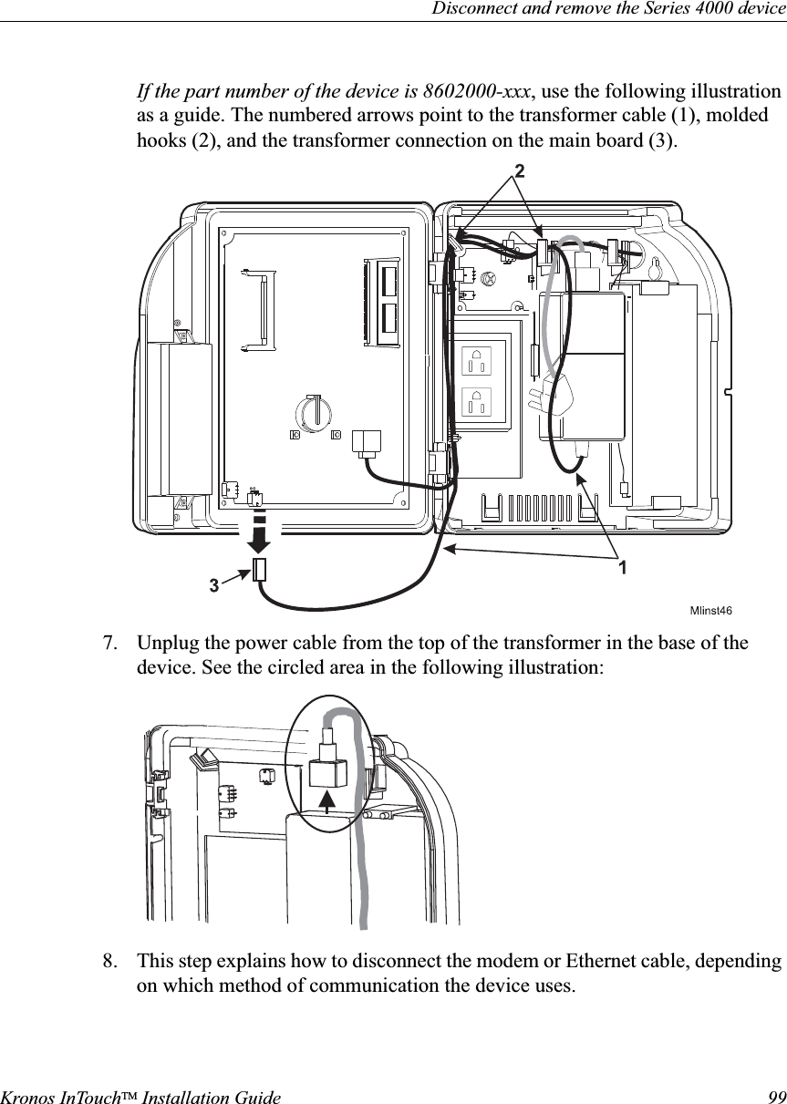
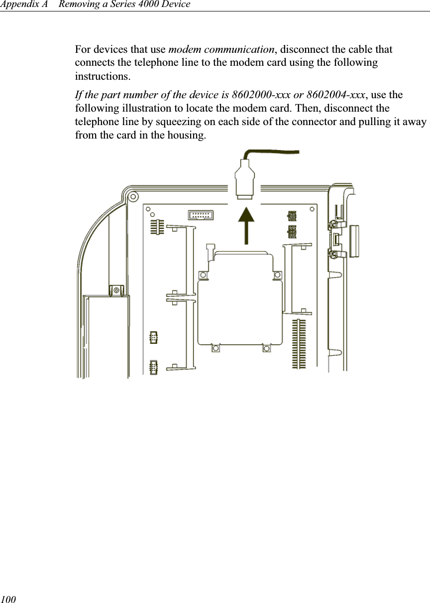
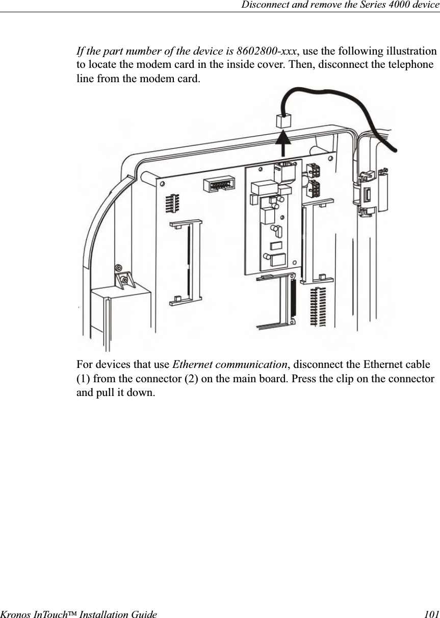
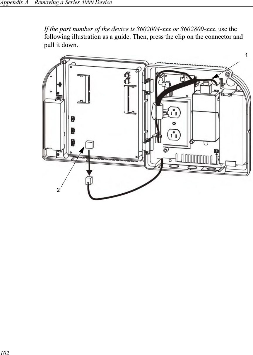
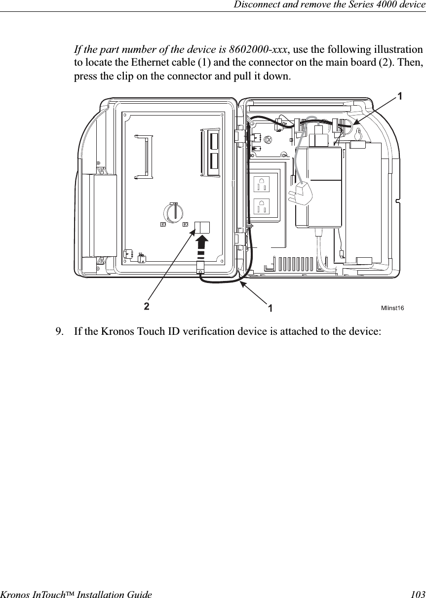
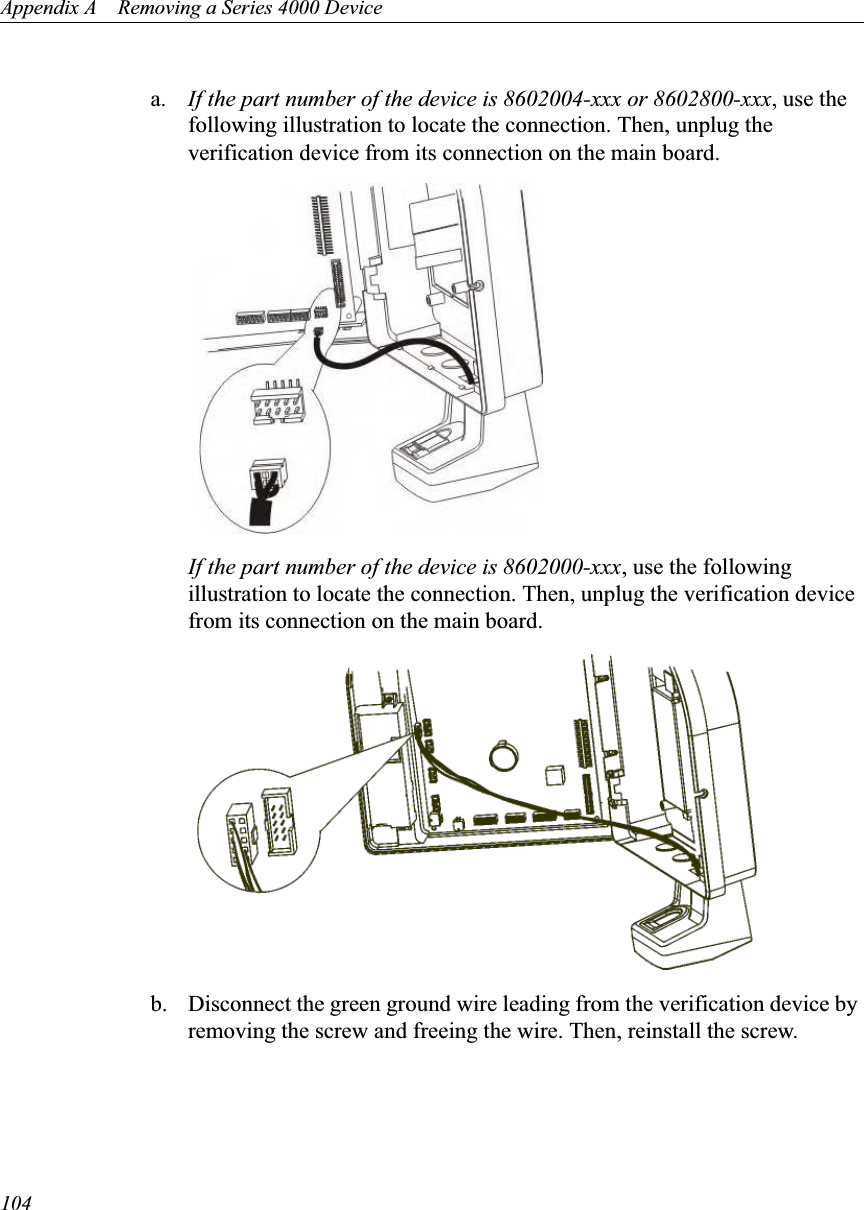
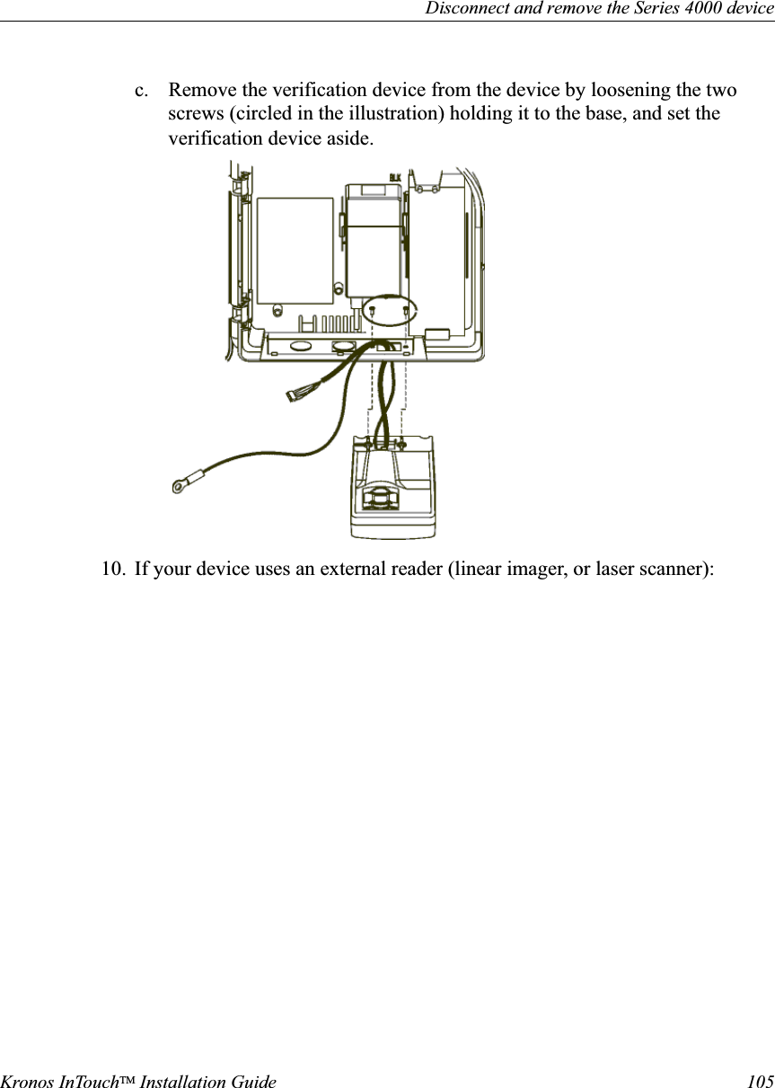
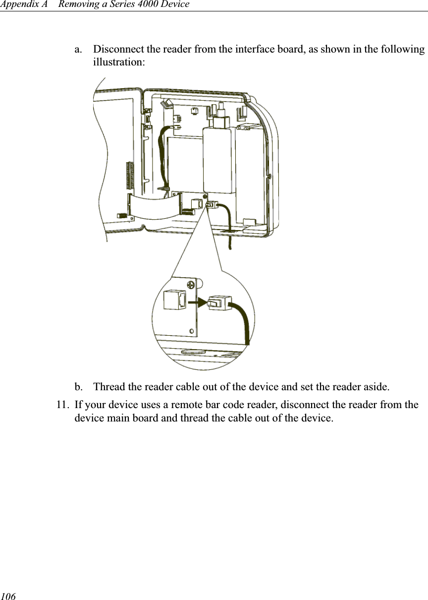
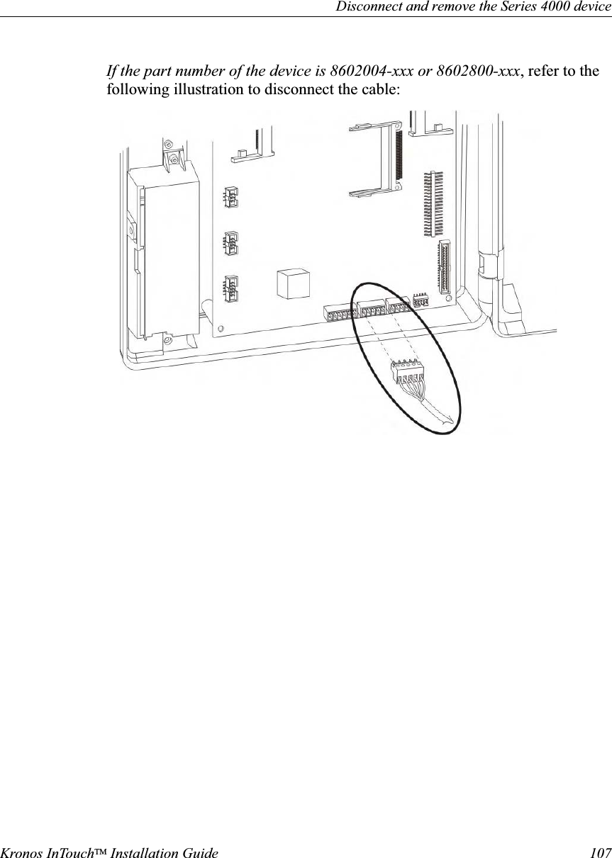
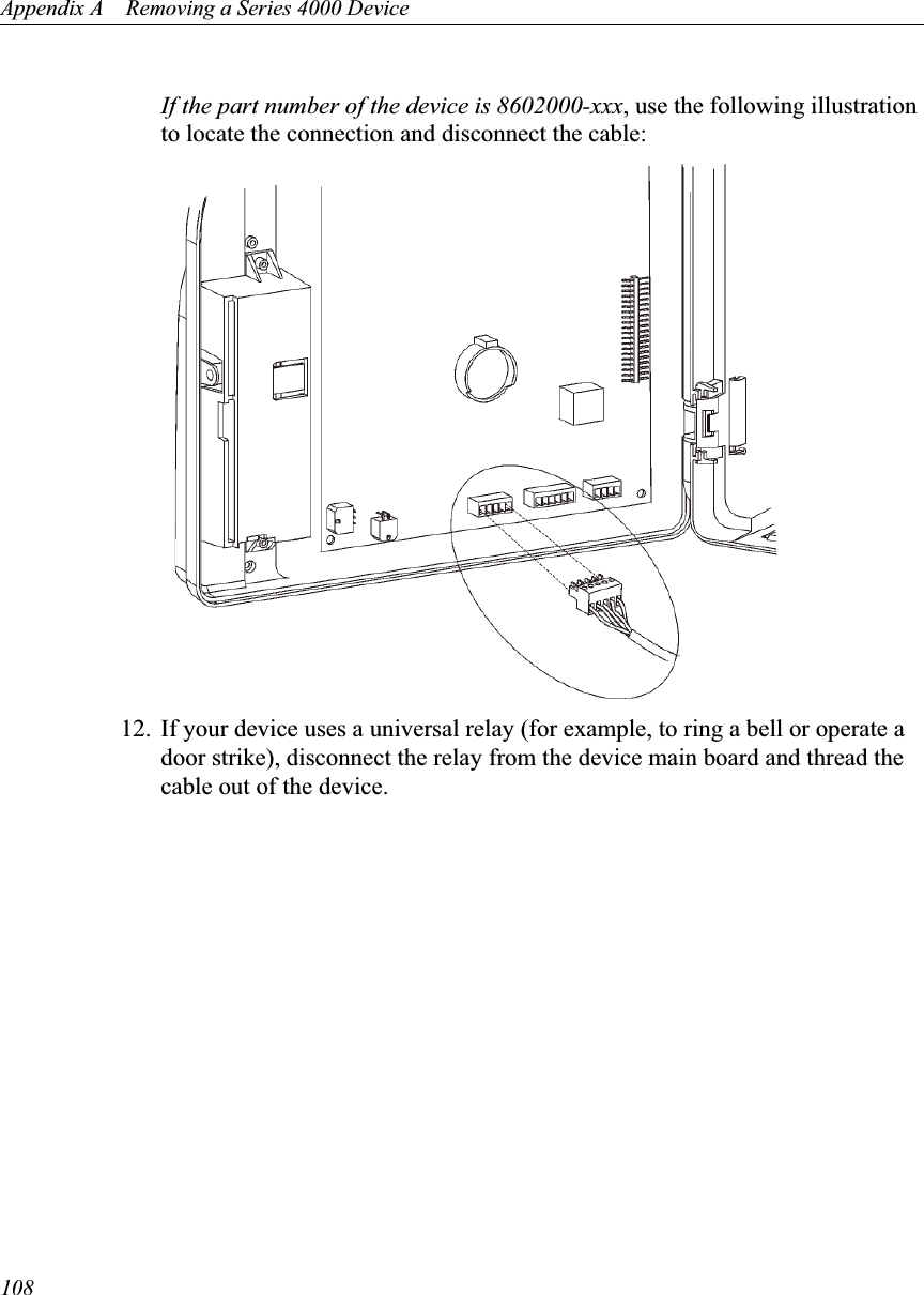
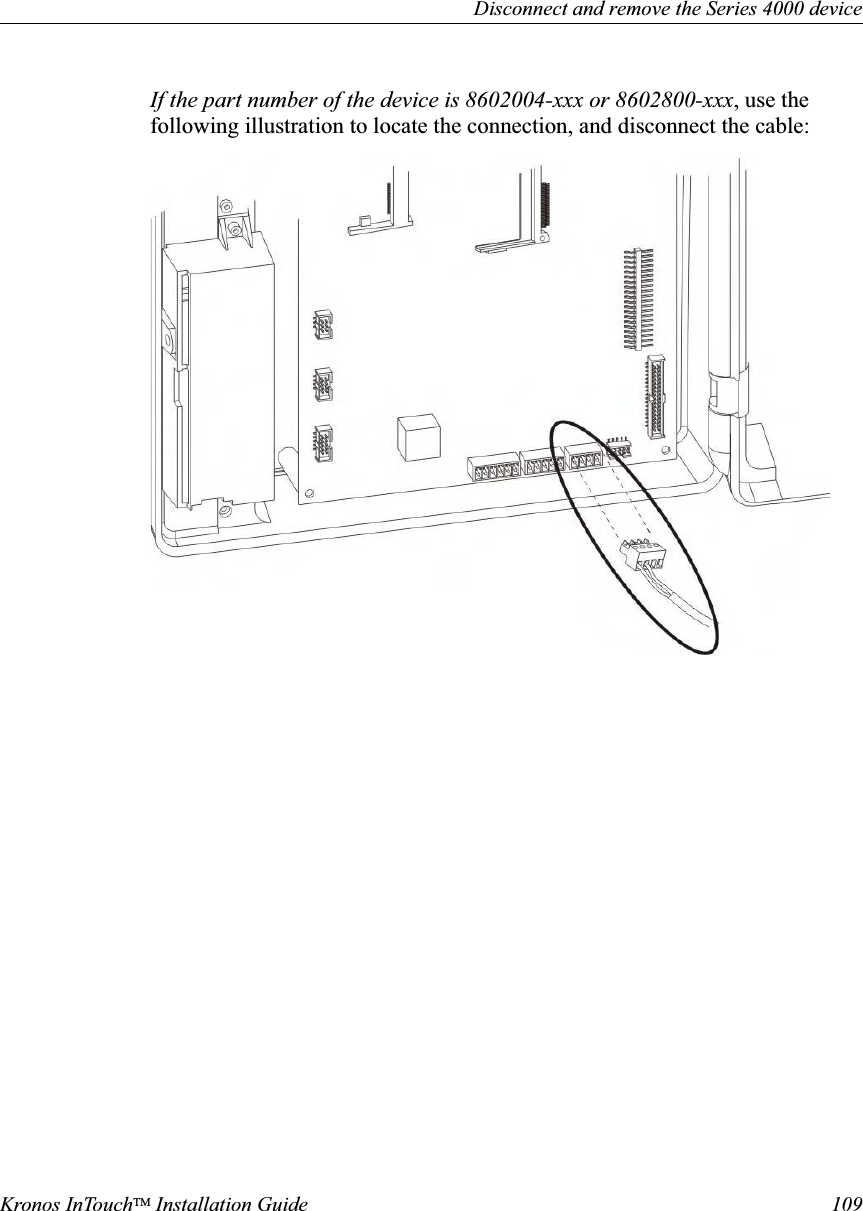
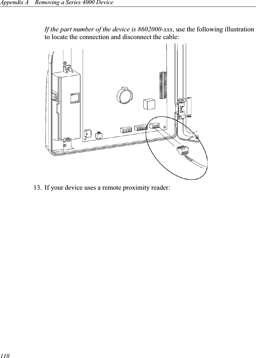
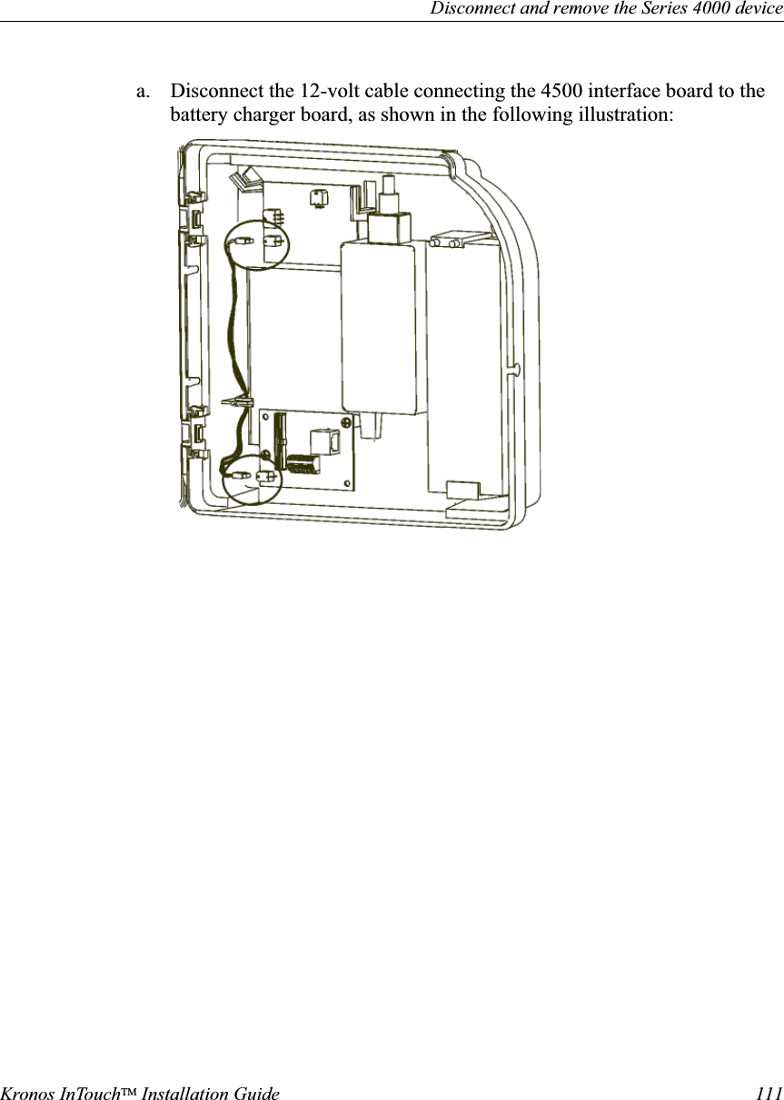
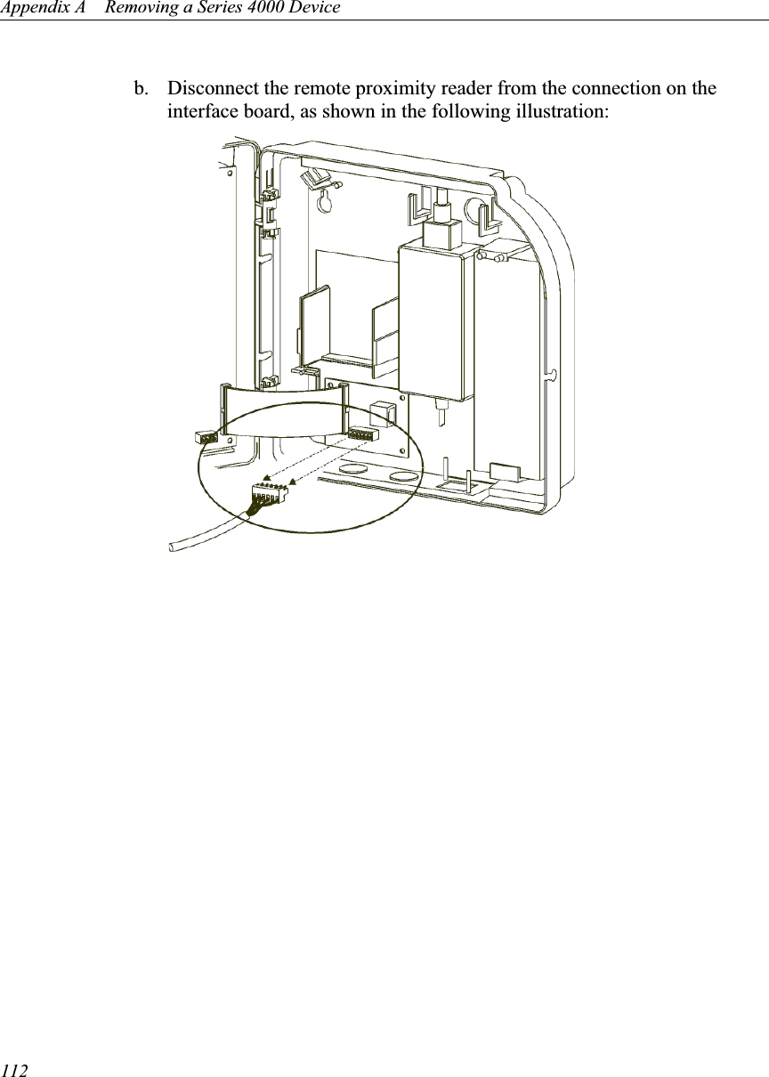
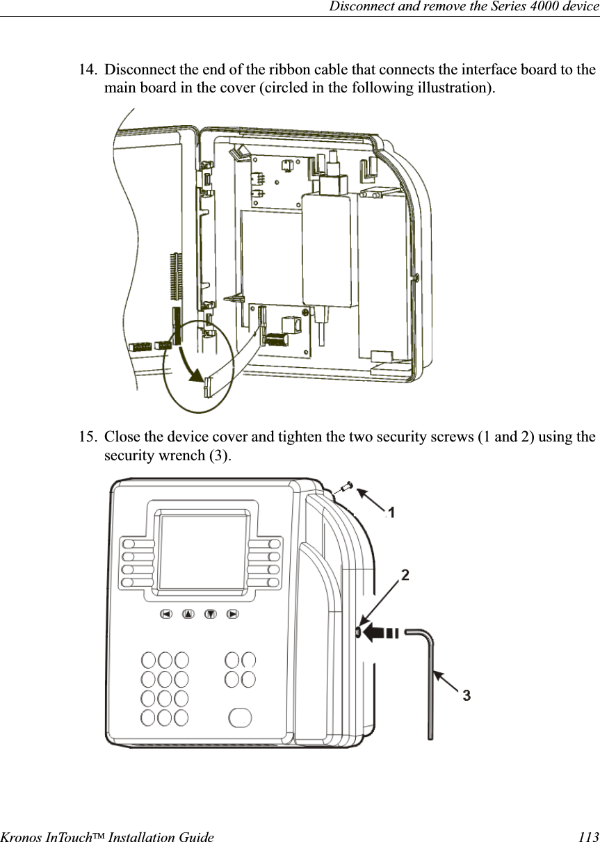
![Chapter 1 Before You Install the Kronos InTouchTM14Location• The Kronos InTouchTM is designed for mounting on walls in typical office and indoor manufacturing environments. Recommended wall surfaces are drywall (sheetrock) and wood.• Install the Kronos InTouchTM in an area where the screen is not exposed to direct sunlight or other high-intensity lighting that could make the screen difficult to read.• Ensure that the location for the Kronos InTouchTM falls within the following temperature and humidity ranges:– Temperature ranges:Operating: 0 to 40 degrees Celsius (32 to 104 degrees Fahrenheit)Storage: -20 to +70 degrees Celsius (4 to 158 degrees Fahrenheit)– Humidity range (operating and storage): 10% to 95% non-condensingAccess• New location — To provide optimal access to the Kronos InTouchTM for the widest range of users, Kronos recommends that the top two mounting screws be no higher than 54 and 7/8 inches (1.4 meters) above the floor. • Existing location — If you are replacing an existing Kronos Series 4000 device, you can use the same location (54 and 3/8 inches [1.4 meters] above the floor) as long as it otherwise conforms to the guidelines and specifications described in this chapter.(To remove an installed Kronos Series 4000 device, see Appendix A, “Removing a Series 4000 Device,” on page 87.)• ADA (Americans with Disabilities Act) compliance:– The 54 and 7/8 inch height specification (1.4 meters) ensures that no part of the Kronos InTouchTM that personnel will physically use (badge reader, keypad) will be higher than the limit set by the ADA. – Devices mounted on a wall must not protrude more than 4 inches (10 cm) from the wall. You must mount the Kronos InTouchTM directly to the wall.](https://usermanual.wiki/Kronos/8609K003/User-Guide-1553799-Page-14.png)