Manual

Document Part Number: Select View > Master Pages to add the part number and revision
Document Revision:
Series 4000
User’s Guide
Series 4000 Badge Terminal
Presents basic concepts of the Series 4000 badge terminal,
instructions for performing functions at the Series 4000
terminal, maintaining and servicing the terminal, and
troubleshooting error conditions.
Document Part Number: 4702574-001
Document Revision: Draft of Rev. C
The information in this document is subject to change without notice and should not be construed as a commitment
by Kronos Incorporated. Kronos Incorporated assumes no responsibility for any errors that may appear in this
manual. This document or any part thereof may not be reproduced in any form without the written permission of
Kronos Incorporated. All rights reserved. Copyright 2001.
CardSaver, Datakeeper, Datakeeper Central, Gatekeeper, Gatekeeper Central, Imagekeeper, Jobkeeper,
Jobkeeper Central, Keep.Trac, Kronos, the Kronos logo, ShopTrac, ShopTrac Pro, the ShopTrac logo, Solution In A
Box, Start.Time, TeleTime, Timekeeper, Timekeeper Central, TimeMaker, and Visionware are registered trademarks
of Kronos Incorporated. CommLink, Comm.Mgr, DKC/Datalink, HyperFind, Improving the Performance of People
and Business, Kronos Connect, Kronos e-Central, Labor Plus, Prism, Smart Scheduler, Starter Series, Start.Labor,
Start.Quality, Start.WIP, Tempo, the Tempo logo, Timekeeper Decisions, Timekeeper Express, Timekeeper Web,
Workforce Activities, Workforce Accruals, Workforce Central, Workforce Central Suite logo, Workforce Decisions,
Workforce Express, Workforce Manager, Workforce Scheduler, Workforce Smart Scheduler, Workforce TeleTime,
Workforce Timekeeper, Workforce Genie, Workforce MobileTime, Workforce Professional Time, and Workforce Web
are trademarks of Kronos Incorporated.
All other trademarks or registered trademarks used herein are the property of their respective owners and are used
for identification purposes only.
When using and applying the information generated by Kronos products, customers should ensure that they comply
with the applicable requirements of federal and state law, such as the Fair Labor Standards Act.
RADIO AND TELEVISION INTERFERENCE
CAUTION: Changes or modifications not expressly approved by the manufacturer could void the user's authority to
operate the equipment.
This equipment has been tested and found to comply with the limits, pursuant to Part 15 of the FCC rules. These
limits are designed to provide reasonable protection against harmful interference in a residential installation. This
equipment generates, uses and can radiate radio frequency energy and, if not installed and used in accordance with
the instructions, may cause harmful interference to radio communications. However, there is no guarantee that
interference will not occur in a particular installation. If this equipment does cause harmful interference to radio or
television reception, which can be determined by turning the equipment off and on, the user is encouraged to try to
correct the interference by one or more of the following measures:
- Reorient or relocate the receiving antenna.
- Increase the separation between the equipment andthe receiver.
- Connect the equipment into an outlet on a circuit different from that to which the receiver is connected.
- Consult the dealer or an experienced radio/TV technician for help.
You may also find helpful the following booklet, prepared by the FCC: "How to Identify and Resolve Radio-TV
Interference Problems." This booklet is available from the U.S. Government Printing Office, Washington D.C.
20402.
Changes and Modifications not expressly approved by the manufacturer or registrant of this equipment can void
your authority to operate this equipment under Federal Communications Commissions rules.
Canadian DOC Compliance
This digital apparatus does not exceed the Class A limits for radio noise emissions from digital apparatus set out in
the Radio Interference Regulations of the Canadian Department of Communications.

Cet appareil numérique respecte les limites de rayonnement de bruits radioélectriques applicables aux appareils
numériques de classe A, prévues au Règlement sur le matériel brouilleur du ministère des Communications du
Canada.
EN 55022 (CISPR 22)
This product is a Class A product. In a domestic environment, it may cause radio interference in which case the user
may be required to take adequate measures.
Published by Kronos Incorporated
297 Billerica Road, Chelmsford, Massachusetts 01824-4119 USA
Phone: 978-250-9800, Fax: 978-367-5900
Kronos Incorporated Global Support: 1-800-394-HELP (1-800-394-4357)
For a complete list of the international subsidiaries, see the following Kronos Incorporated Web page:
http://www.kronos.com/discover/about/worldwide.htm
Document Revision History
Document Revision Product Version Release Date
A 1.0 August 2001
B 1.0 November 2001
Rev C Draft 1.2 TBD
Contents
About This Guide
Organization of This Guide ........................................................................... x
Abbreviations and Terms .............................................................................xi
Related Documents ......................................................................................xii
Chapter 1: Overview
What Are the Series 4000 Terminals? ........................................................1-2
Standard Hardware Features ................................................................1-2
Optional Devices ..................................................................................1-3
Physical Description of the Terminal ..................................................1-4
Terminal Display .................................................................................1-6
Understanding How the Series 4000 Terminal Operates ...........................1-7
How the Terminal Functions with the Host Application .....................1-7
Cross-punching ....................................................................................1-8
Modes of Operation .............................................................................1-8
Labor Tracking Functions ....................................................................1-9
Entering Data at the Series 4000 Terminal ...............................................1-10
Using the Badge Reader .....................................................................1-10
Using the Keypad and Soft Keys .......................................................1-11
Guidelines for Entering Information Using the Terminal ..................1-12
Chapter 2: Employee Functions
What Are Employee Functions? .................................................................2-2
Performing Employee Functions ................................................................2-4
Cancel Meal Deduction ........................................................................2-4
End Activity .........................................................................................2-4
Enter Tips .............................................................................................2-5
Labor Transfer .....................................................................................2-5
Pay Code Hours Edit ............................................................................2-6

Contents
vi Kronos
Pay Code Money Edit .......................................................................... 2-7
Review Punches ................................................................................... 2-8
Simple Punch ....................................................................................... 2-8
Start Activity ....................................................................................... 2-9
View All Messages .............................................................................. 2-9
View Current Schedule ...................................................................... 2-10
View Future Schedule ....................................................................... 2-10
View Punch Status ............................................................................. 2-11
View Totals ....................................................................................... 2-11
Chapter 3: Supervisor Functions
What Are Supervisor Functions? ............................................................... 3-2
Performing Supervisor Functions .............................................................. 3-5
Add Punch ........................................................................................... 3-5
Change Password ................................................................................. 3-6
Delete Punch ........................................................................................ 3-7
Display On/Off Premise Employees ................................................... 3-8
Global Home Employee Restriction Override .................................... 3-8
Global Non-Home Employee Restriction Override ............................ 3-9
Pay Code Hours Adjustment ........................................................... 3-10
Single Home Employee Restriction Override ................................... 3-11
Single Non-Home Employee Restriction Override ........................... 3-12
View Employee Information ............................................................. 3-12
Chapter 4: Maintaining the Terminal
Maintenance Basics .................................................................................... 4-2
Types of Maintenance ......................................................................... 4-2
Required Tools .................................................................................... 4-2
Safety Considerations .......................................................................... 4-3
Handling Static-Sensitive Components ............................................... 4-3
Obtaining Replacement Parts .............................................................. 4-4
Preventive Maintenance ............................................................................. 4-5
Cleaning the Terminal ......................................................................... 4-5
About the Lithium and Lead Acid Batteries ........................................ 4-6
Running Diagnostic Tests and Reports ............................................... 4-7

Contents
Series 4000 Badge Terminal User’s Guide vii
Servicing the Terminal ...............................................................................4-8
Interior of Fully-Assembled Terminal .................................................4-9
Returning the Cover Assembly to Kronos .........................................4-10
Attaching the Cover Assemby to the Terminal ..................................4-15
Performing Basic Configuration at the Series 4000 Terminal ...........4-20
Replacing the Backup Battery Charger Board ...................................4-24
Adjusting the Width of the Badge Reader Slot ..................................4-32
Replacing the Badge Reader Cover ...................................................4-38
Replacing the AC Power Supply (transformer) .................................4-40
What Are the Maintenance Functions? ....................................................4-43
Performing Maintenance Functions .........................................................4-46
Audio Setting (basic configuration) ...................................................4-46
Communication Setting (basic configuration) ...................................4-47
Date/Time Setting (basic configuration) ............................................4-48
Display Setting (basic configuration) ................................................4-49
Symbology Setting (basic configuration) ..........................................4-50
Database Report .................................................................................4-51
Device Status Report ..........................................................................4-51
Ethernet Report ..................................................................................4-52
File System Report .............................................................................4-52
Memory Report ..................................................................................4-53
Readers Report ...................................................................................4-53
Badge Test .........................................................................................4-54
Beeper Test ........................................................................................4-54
Display Test .......................................................................................4-55
Keypad Test .......................................................................................4-55
LED Test ............................................................................................4-56
Sequential Tests .................................................................................4-56
Change Password ...............................................................................4-57
FACTORY DEFAULT ......................................................................4-57
Delete All Punches .............................................................................4-58
Restart ...............................................................................................4-58

Contents
viii Kronos
Chapter 5: Upgrading Terminal Firmware
Overview of a Softload .............................................................................. 5-2
Performing a Softload ................................................................................ 5-3
Chapter 6: Error Messages and Troubleshooting Procedures
Error Messages ........................................................................................... 6-2
Transaction Error Messages ................................................................ 6-2
Other Error Messages .......................................................................... 6-6
Status Messages ................................................................................... 6-8
Troubleshooting ......................................................................................... 6-9
Terminal Hardware Failures ................................................................ 6-9
Troubleshooting Table ....................................................................... 6-10
Verifying the Integrity of the Network .............................................. 6-15
Appendix A: Terminal Specifications
Appendix B: Differences Between the Series 4000 and the Series 400
Terminals
Physical Differences ................................................................................. A-2
Functional Differences .............................................................................. A-3
Glossary
Index
About This Guide
This guide is intended for all users of the Series 4000 timeclock. It describes basic
concepts of the Series 4000 timeclock and contains instructions for performing
operations and executing functions, maintaining and servicing the timeclock, and
troubleshooting error conditions.
This preface contains the following sections:
!Organization of This Guide
!Abbreviations and Terms
!Related Documents

About This Guide
xADP, Inc.
Organization of This Guide
This guide contains the following information:
!Chapter 1, “Overview,” describes the Series 4000 timeclock, explains how the
timeclock operates, and describes how to enter data at the timeclock.
!Chapter 2, “Employee Functions,” describes employee functions and how to
perform them. Examples of employee functions are simple punches and labor
transfers.
!Chapter 3, “Supervisor Functions,” describes supervisor functions and how to
perform them. Examples of supervisor functions are adding and deleting
punches.
!Chapter 4, “Maintaining the Timeclock,” describes how to service the
timeclock and how to perform maintenance functions. Examples of
maintenance functions are configuring the timeclock and running diagnostics.
!Chapter 5, “Upgrading Timeclock Firmware,” contains information about
using the correct versions of the timeclock firmware and downloading
information to the timeclock.
!Chapter 6, “Error Messages and Troubleshooting Procedures,” includes
descriptions and resolutions for error messages and procedures for diagnosing
and resolving error conditions.
!Appendix A, “Timeclock Specifications,” lists the physical characteristics of
the Series 4000 timeclock.
!Appendix B, “Differences Between the Series 4000 and the Series 400
Timeclocks,” explains the physical and functional differences between the
Series 4000 timeclock and the Series 400 timeclock. This is useful for users
who are familiar with using the Series 400 timeclocks.
!“Glossary,” contains a list of terms related to the use and configuration of the
Series 4000 timeclock.

Abbreviations and Terms
Series 4000 Badge Timeclock User’s Guide xi
Abbreviations and Terms
The guide uses the following abbreviations and terms:
Abbreviation Meaning
CSA Canadian Standards Association
DCM Data Collection Manager
FIFO first-in-first-out data queue
FRU field replaceable unit
I/O input/output
LCD liquid crystal display
LED light-emitting diode
PIN personal identification number
RAM random access memory
TCP/IP Transmission Control Protocol/Internet Protocol
UL Underwriter’s Laboratory
UPC universal product code

About This Guide
xii ADP, Inc.
Related Documents
The following list includes the other documentation in the Series 4000 timeclock’s
documentation set. Unless otherwise noted, these documents are not included in
the box with the Series 4000 timeclock; you must order them separately.
!Series 4000 Badge Timeclock Installation Guide provides step-by-step
instructions for installing the Series 4000 timeclock and performing basic
configuration. This document is shipped with the Series 4000 timeclock.
!The following installation guides ship with the corresponding optional device:
– Backup Battery Option Kit Installation Guide
– Internal AC Outlet Option Kit Installation Guide
Chapter 1
Overview
This chapter contains the following sections:
!What Are the Series 4000 Timeclocks?
!Understanding How the Series 4000 Timeclock Operates
!Entering Data at the Series 4000 Timeclock

Chapter 1 Overview
1-2 ADP, Inc.
What Are the Series 4000 Timeclocks?
The Series 4000 timeclocks are data collection devices designed to communicate
with the ADP Enterprise Labor Management Suite of host applications.
The Series 4000 timeclock collects information entered by employees using the
barcode reader and the keypad. You use your host application software to collect
data from the timeclocks to track and process labor-related data, generate
management reports, and transfer information to your payroll service.
The Series 4000 timeclock features include the following:
!Schedule enforcement, which controls when specific employees can swipe in
and out
!Display of employee names, vacation, sick time, and other totals (host
application dependent)
!Messaging, which allows the timeclock to display messages to individual
employees (host application dependent)
!Function keys to perform various functions and transactions, such as labor
account transfers and pay code transactions
Standard Hardware Features
The hardware features of the Series 4000 timeclock include the following:
!29-key keypad including 8 user-definable function soft keys
!4.7 inches (11.9380 cm) 1/4 VGA 4X40 FSTN liquid crystal display (LCD)
!AC transformer
!Internal beeper
!Wall-mountable enclosure

What Are the Series 4000 Timeclocks?
Series 4000 Badge Timeclock User’s Guide 1-3
!Integrated bar code badge reader supporting use of the following codes:
– Interleaved 2-of-5
–Code3-of-9
– Codabar
– Universal Product Code (UPC-A and UPC-E with optional 2- and
5-character supplements)
– European Article Numbering (EAN-8 and EAN-13 with optional 2- and
5-character supplements)
– Code 128 (compressed and uncompressed)
!Light-emitting diodes (LEDs) that indicate whether an employee’s badge is
read successfully, and whether the timeclock is connected to an external
power source or operating on battery backup
Optional Devices
You can order the following optional devices separately and connect them to the
Series 4000 timeclock. Installation instructions are provided with each device.
!Backup Battery Option (part number 8601763-002)
Rechargeable 12 VDC lead-acid battery that you install to allow the Series
4000 timeclock to remain fully operational for up to 2 hours in the absence of
AC power.
!Internal AC Outlet Option Kit (part number 8601824-002)
AC outlet that you can install inside the timeclock and connect to an AC
power line. This device allows you to secure the AC power connection inside
the timeclock.
Chapter 1 Overview
1-4 ADP, Inc.
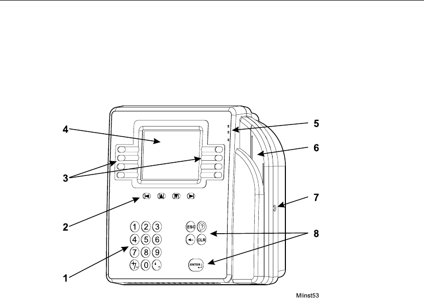
Physical Description of the Timeclock
This section includes an illustration of the timeclock and brief descriptions of its
parts. For a map of the timeclock’s internal parts, see “Interior of Fully-
Assembled Timeclock” on page 4-9.

What Are the Series 4000 Timeclocks?
Series 4000 Badge Timeclock User’s Guide 1-5
Number Timeclock Part
1Numeric keypad for data entry—Use to enter information when
performing transactions and functions at the timeclock.
2Navigational keys—Use to move within fields and scroll through lists.
3Soft keys—Use to initiate transactions and functions at the timeclock.
You program each soft key using the Data Collection Manager (DCM).
4Display—1/4 VGA screen that displays soft key labels, possible
functions, transaction steps, and transaction output.
5LEDs—Visual indicators:
The top LED is green and flashes when the timeclock successfully reads a
badge that is swiped by a user.
The middle LED is amber and flashes when the timeclock does not
successfully reads a badge that is swiped by a user.
The bottom LED is amber and indicates whether the timeclock is
receiving power.
6Badge reader (barcode)—Used to read employee, supervisor, and
maintenance badges when swiping in and out and performing
transactions and functions.
7Security screw—Used to secure the timeclock’s cover. Use the supplied
security screw wrench to lock and unlock the cover.
8Additional keys—ESC, Help, backspace and delete, CLEAR, and
ENTER.
Chapter 1 Overview
1-6 ADP, Inc.
Timeclock Display
The Series 4000 timeclock is equipped with a backlit liquid crystal display to
provide users with information such as:
!Current time
!Mode in which the timeclock is operating
!Transaction prompts
!Messages
The LCD display is a 1/4 VGA display that presents you with possible functions,
transaction steps, and transaction output.
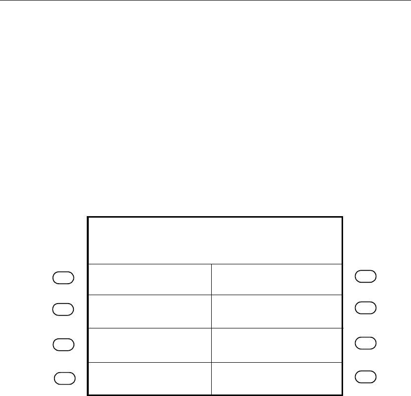
The following figure shows a sample idle display:
When you have more than 8 soft keys configured on the timeclock, the More soft
key appears on the first screen and the 8th soft key appears on the second screen.
You use the More soft key to access the second screen.
Review Punches
Punch Status
Employee Report
Current Schedule
Fri24-Aug-2001
Global message area
2:03 PM
Future Schedule

Understanding How the Series 4000 Timeclock Operates
Series 4000 Badge Timeclock User’s Guide 1-7
Understanding How the Series 4000 Timeclock Operates
Before using the Series 4000 timeclock to perform time and attendance, and labor
tracking functions, it is helpful to understand:
!How the timeclock functions with the host application
!Cross-punching
!Modes of operation
!Labor tracking functions
How the Timeclock Functions with the Host Application
You use the host application to configure employees and employee information
such as schedules, schedule margins, shift length, punch restrictions, and labor
accounts. You then use the host application software to send this information to
the Series 4000 timeclock. The timeclock accepts or restricts employee punches
based on this downloaded information. Non-home employees can use a timeclock
if cross punching is enabled from the host application.
When you swipe in at the Series 4000 timeclock, the punch information is
collected and stored in the first-in-first-out (FIFO) data queue of the timeclock’s
memory. You use the host application to collect the stored data. The host
application totals the hours, computes any overtime, calculates the wages, tracks
the labor, and generates reports based on the data it collects from the timeclocks.
If your host application is eTIME, you use its data collection timeclock
communication feature (Commlink application) to define which functions and
transactions users can perform at the timeclocks. You also use the host
application’s communication functions to transfer data between the application
and the timeclock. For more information, see the eTIME System Manager’s Guide
and the eTIME online Help.

Chapter 1 Overview
1-8 ADP, Inc.
If your host application is Enterprise eTIME, you use Data Collection Manager
(DCM) to define which functions and transactions users can perform at the
timeclocks. You also use DCM to collect, transfer, and monitor the flow of data
between the host application and the Series 4000 timeclock. For more
information, see the Data Collection Manager System Administrator’s Guide and
the DCM online Help.
Cross-punching
The cross-punching feature enables employees to use timeclocks that they are not
assigned to. Each employee is assigned to a specific timeclock. They are
considered a home employee to that particular timeclock. At times, an employee
may need to use a timeclock that they are not assigned to for simple punching
purposes. In this case, they are considered a non-home employee. This is where
the cross-punching feature comes in.
You enable the cross-punching feature in the timeclock’s data collection
communication feature.
Modes of Operation
The Series 4000 timeclock operates in three modes. Each mode has its own set of
functions and requires a specially coded badge for access.
!Employee
The Series 4000 timeclock most often operates in Employee Mode. In
Employee Mode, the timeclock accepts punch data entered using the badge
reader and keypad. In this mode, only “home” employees (employees who
have been assigned to the timeclock from the host application) whose badge
number or employee ID have been downloaded from the host application can
use the timeclock. If cross-punching is enabled in the timeclock program, then
non-home employees can use the timeclock as well as home employees.

Understanding How the Series 4000 Timeclock Operates
Series 4000 Badge Timeclock User’s Guide 1-9
!Supervisor
Supervisor Mode allows you to perform tasks such as editing employee
punches, adding missed employee punches, and overriding restrictions to
allow employees to punch. Supervisor Mode is accessible only to those who
have a supervisor badge and unique password.
!Maintenance
Maintenance Mode allows you to display technical information about the
timeclock, execute the timeclock’s self-diagnostic tests, and perform
timeclock configuration functions. Maintenance Mode is available only to
those who have a maintenance badge and unique password.
Labor Tracking Functions
In addition to performing time and attendance functions, your Series 4000
timeclock may be configured to perform labor tracking functions using either
departments or labor accounts.
If your Series 4000 timeclock is configured to use departments, an employee’s
time is associated with a single cost center, for example, shipping, medical, or
engineering.
If your Series 4000 timeclock is configured to use labor accounts, an employee’s
time can be associated with multiple labor levels. Typically, when labor accounts
are used, an employee’s time is associated with cost centers that have a
hierarchical relationship to each other, for example, programmer-software-
engineering or drill press operator-tooling-manufacturing.
When your Series 4000 timeclock is initialized with the host application, a list of
valid department numbers and labor levels can be downloaded to the timeclock.
If your timeclock is configured to perform labor account validation, employees
enter labor levels by pressing the numeric keys on the timeclock or by accepting a
default number by pressing ENTER. The Series 4000 timeclock validates each
labor level against the list of labor levels stored in its database. If you attempt to
enter an invalid labor level, the entry is rejected and an error message appears on
the display.

Chapter 1 Overview
1-10 ADP, Inc.
Entering Data at the Series 4000 Timeclock
When entering data at the Series 4000 timeclock, you use the timeclock’s badge
reader, keypad, and soft keys.
Using the Badge Reader
You most often enter data at the Series 4000 timeclock by swiping a badge
through the timeclock’s badge reader. To allow the timeclock to read the badge
successfully, users should:
!Hold the badge so that the bar code is positioned on the back left edge.
!Swipe the badge through the reader’s slot from top-to-bottom or bottom-to-
top.
If the Series 4000 timeclock reads the badge successfully, the green LED
illuminates and its internal beeper emits a single tone. If the timeclock fails to read
the badge, the amber LED illuminates, its internal beeper emits three tones in
quick succession, and an error message appears on the display.

Entering Data at the Series 4000 Timeclock
Series 4000 Badge Timeclock User’s Guide 1-11
Using the Keypad and Soft Keys
The following table summarizes the timeclock’s keys:
Keys Use
Soft keys These keys are the timeclock’s function keys. You can configure
each of these keys with functions for Employee Mode and
Supervisor Mode. You configure these keys using your host
application software.
The bottom soft keys on each side of the display are used as toggle
keys in transactions. Press these soft keys to toggle between
options.
Navigational keys Use the left and right arrow keys to move the cursor within a text
field.
Use the up and down arrow keys to move the cursor to a different
text field and to scroll through output.
Numeric keys (0 - 9) Use to enter numeric data such as personal identification numbers
(PINs), department numbers, badge numbers, and so on.
+ or - keys At timeclocks so configured, press the + and - keys to enter
positive or negative values to adjust settings such as contrast and
volume.
’ or . keys At timeclocks so configured, press the ’ and . keys to enter tip
(decimal) data.
ESC Use for the following:
!To go back one screen
!To cancel the transaction you are performing
!To restore the previous settings on a configuration screen
Backspace Press to clear data entered by the user one-character-at-a-time
from the right.
CLR Press to clear all data in a field.
ENTER Press to accept data in a field and move to the next field. If you are
in the last field of a transaction, pressing ENTER initiates the
transaction validation.

Chapter 1 Overview
1-12 ADP, Inc.
Guidelines for Entering Information Using the Timeclock
Use the following guidelines when entering information using the keypad:
!To display settings for a menu item, press the soft key next to the menu item.
!To save settings on a screen, press ENTER at the last prompt.
To cancel the transaction you are performing, press ESC at any time.
!To move the cursor in a text field, use the left and right arrow keys directly
under the display.
!To move the cursor to different text fields, use the up and down arrow keys
directly under the display.
!The active text field (field in which the cursor is currently located) is
indicated by an outline of the text box and a flashing cursor.
!If you enter characters in a field that already contains data, the existing data is
not overwritten; it is pushed to the right. To remove individual characters,
position the cursor immediately to the right of the characters, and press the
Backspace key (").
!To clear all characters in a field, press the CLR key.
!If you complete a field incorrectly and move to the next field, an error
message appears at the top of the display.
!To save data that you entered, press the ENTER key at the last field on the
screen.
!To restore the previous settings on a configuration screen, press the ESC key.
!Black up and down arrows appear at the bottom middle of the screen if there
is additional information to display before or after the current screen. The
arrows look like this:
Use the up and down arrow keys directly under the screen to move to the
various screens.
Chapter 2
Employee Functions
This chapter contains the following sections:
!What Are Employee Functions?
!Performing Employee Functions
Chapter 2 Employee Functions
2-2 ADP, Inc.
What Are Employee Functions?
Use Employee functions to perform activities such as a simple punch, labor
transfer, start activity, and end activity. With the timeclock in Employee Mode
(default mode), you initiate an employee function by pressing the corresponding
soft key.
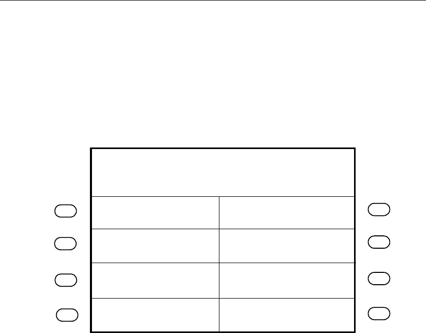
The following figure shows a sample Employee Mode screen:
Review Punches
View Punch Status
Employee Report
View Current Schedule
Fri Aug - 24 - 2001
Global message area
2:03 PM
View Future Schedule

What Are Employee Functions?
Series 4000 Badge Timeclock User’s Guide 2-3
The following list shows the Employee functions that you can perform using the
Series 4000 timeclock. The transaction names are the default names. When setting
up these transactions using the host application software, you can customize the
names.
Note
Your timeclock can only perform the following functions after the soft keys have
been configured using the host application software.
!Cancel Meal Deduction
!End Activity
!Enter Tips
!Labor Transfer
!Pay Code Hours Edit
!Pay Code Money Edit
!Review Punches
!Simple Punch
!Start Activity
!View All Messages
!View Current Schedule
!View Future Schedule
!View Punch Status
!View Totals
The remainder of this chapter contains more information about each of these
Employee functions.

Chapter 2 Employee Functions
2-4 ADP, Inc.
Performing Employee Functions
This section describes the steps you must follow to perform employee functions at
the Series 4000 timeclock.
Cancel Meal Deduction
Your Series 4000 timeclock can be configured to automatically deduct time for
meals so that employees do not have to punch out or in for meals or breaks. Use
the Cancel Meal Deduction transaction to override the automatic deduction for
special situations such as when employees work through meals or breaks.
End Activity
Use the End Activity transaction to associate an end time with a specific activity
that you just completed.
Step Display Action
1 Idle screen Press the Cancel Meal Deduction soft key.
2 Enter Badge Do one of the following:
!Swipe your badge from top to bottom.
!Type your badge number using the keypad, and
press ENTER.
Step Display Action
1 Idle screen Press the End Activity soft key.
2 Enter Badge Do one of the following:
!Swipe your badge from top to bottom.
!Type your badge number using the keypad, and
press ENTER.

Performing Employee Functions
Series 4000 Badge Timeclock User’s Guide 2-5
Enter Tips
Use the Enter Tips transaction to record tips that you have received.
Labor Transfer
Use the Labor Transfer transaction to specify to which labor account your time
worked should be applied to. Your timeclock can have up to 7 labor levels.
Step Display Action
1 Idle screen Press the Enter Tips soft key.
2 Enter Tips Type the tip amount and press ENTER.
3 Enter Badge Do one of the following:
!Swipe your badge from top to bottom.
!Type your badge number using the keypad, and
press ENTER.
Step Display Action
1 Idle screen Press the Labor Transfer soft key.
2 Labor Level xDo one of the following to each labor level:
!Press ENTER to accept the default labor level.
!Press CLR, type a new labor level, and press
ENTER.
3 Enter Badge Do one of the following:
!Swipe your badge from top to bottom.
!Type your badge number using the keypad, and
press ENTER.

Chapter 2 Employee Functions
2-6 ADP, Inc.
Pay Code Hours Edit
Use the Pay Code Hours Edit transaction to associate a period of time you specify
to a pay code. This is especially useful for entering non-productive time such as
sick, vacation, or personal time where employees are not able to punch in and out.
Step Display Action
1 Idle screen Press the Pay Code Hours Edit soft key.
2 Hours worked Type the hours and press ENTER.
3 Date worked Do one of the following:
!Press ENTER to accept the default date.
!Press CLR, type a new date using mm/dd/yyyy
format, and press ENTER.
4 Time work started Type the 4-digit time using 24-hour format, then
press ENTER.
5 Pay Code Do one of the following:
!Press ENTER to accept the default pay code.
!Press CLR, type a new pay code, and press
ENTER.
6 Affect OT Do one of the following:
!Press ENTER to accept the default.
!Use the toggle soft keys to select Yes or No, and
press ENTER.
7 Activity Code (optional) Do one of the following:
!Press ENTER to accept the default activity code.
!Press CLR, type a new activity code, and press
ENTER.
8 Labor Account (optional) Do one of the following:
!Press ENTER to accept the default labor account.
!Press CLR, type a new labor account, and press
ENTER.
9 Enter Badge Do one of the following:
!Swipe your badge from top to bottom.
!Type your badge number using the keypad, and
press ENTER.

Performing Employee Functions
Series 4000 Badge Timeclock User’s Guide 2-7
Pay Code Money Edit
Use the Pay Code Money Edit transaction to enter a money amount for an
employee, as opposed to having the host application calculate the information
based on start and end times. The timeclock displays a currency format
placeholder when prompting for the money amount.
Step Display Action
1 Idle screen Press the Pay Code Money Edit soft key.
2 Money amount Type the money amount and press ENTER.
3 Date worked Do one of the following:
!Press ENTER to accept the default date.
!Press CLR, type a new date using mm/dd/yyyy
format, and press ENTER.
4 Time work started Type the 4-digit time using 24-hour format, then
press ENTER.
5 Pay Code Do one of the following:
!Press ENTER to accept the default pay code.
!Press CLR, type a new pay code, and press
ENTER.
6 Activity Code (optional) Do one of the following:
!Press ENTER to accept the default activity code.
!Press CLR, type a new activity code, and press
ENTER.
7 Labor Account (optional) Do one of the following:
!Press ENTER to accept the default labor account.
!Press CLR, type a new labor account, and press
ENTER.
8 Enter Badge Do one of the following:
!Swipe your badge from top to bottom.
!Type your badge number using the keypad, and
press ENTER.

Chapter 2 Employee Functions
2-8 ADP, Inc.
Review Punches
Use the Review Punches transaction to view your punches. The timeclock will
default to a maximum of the past 72 hours unless your host application is
configured differently.
Simple Punch
Use the Simple Punch transaction to make an in or out punch by swiping your
badge through the Series 4000 timeclock’s integral badge reader or by keying in
your badge number using the keypad.
Note
You do not need to press any keys prior to keying in your badge number as you
had to do with the Series 400 timeclocks.
Step Display Action
1 Idle screen Press the Review Punches soft key.
2 Enter Badge Do one of the following:
!Swipe your badge from top to bottom.
!Type your badge number using the keypad, and
press ENTER.
Step Display Action
1 Idle screen Do one of the following:
!Swipe your badge from top to bottom.
!Type your badge number using the keypad, and
press ENTER.

Performing Employee Functions
Series 4000 Badge Timeclock User’s Guide 2-9
Start Activity
Use the Start Activity transaction to associate the time you are about to work with
a specific activity.
View All Messages
Use the View All Messages transaction to view any messages you have. You can
have multiple messages assigned to you.
Step Display Action
1 Idle screen Press the Start Activity soft key.
2 Activity Code Do one of the following:
!Accept the default activity code by pressing
ENTER.
!Press CLR, type a new activity code, and press
ENTER.
3 Enter Badge Do one of the following:
!Swipe your badge from top to bottom.
!Type your badge number using the keypad, and
press ENTER.
Step Display Action
1 Idle screen Press the View All Messages soft key.
2 Enter Badge Do one of the following:
!Swipe your badge from top to bottom.
!Type your badge number using the keypad, and
press ENTER.

Chapter 2 Employee Functions
2-10 ADP, Inc.
View Current Schedule
Use the View Current Schedule transaction to display the start and end times for
the shift that you are currently working.
View Future Schedule
Use the View Future Schedule transaction to display your upcoming schedule.
Depending on what your schedule is set to in your host application, the Series
4000 timeclock can display up to 14 different shifts. For example, if your host
application has a 14-day schedule for you, and 10 days of that schedule have
passed, the timeclock displays the schedule for the remaining 4 days.
Step Display Action
1 Idle screen Press the View Current Schedule soft key.
2 Enter Badge Do one of the following:
!Swipe your badge from top to bottom.
!Type your badge number using the keypad, and
press ENTER.
Step Display Action
1 Idle screen Press the View Future Schedule soft key.
2 Enter Badge Do one of the following:
!Swipe your badge from top to bottom.
!Type your badge number using the keypad, and
press ENTER.

Performing Employee Functions
Series 4000 Badge Timeclock User’s Guide 2-11
View Punch Status
Use the View Punch Status transaction to see whether your last punch was an in or
out punch, date and time of your last punch, and how long ago that punch was
made.
View Totals
Use the View Totals transaction to display total hours amounts, such as accrued
hours or accruals, for a specific employee. This transaction allows you to view
accrued information such as vacation time, sick time, hours worked so far this pay
period, and so on. You use your host application to configure what data you want
to be displayed here.
Step Display Action
1 Idle screen Press the View Punch Status soft key.
2 Enter Badge Do one of the following:
!Swipe your badge from top to bottom.
!Type your badge number using the keypad, and
press ENTER.
Step Display Action
1 Idle screen Press the View Totals soft key.
2 Enter Badge Do one of the following:
!Swipe your badge from top to bottom.
!Type your badge number using the keypad, and
press ENTER.

Chapter 2 Employee Functions
2-12 ADP, Inc.
Chapter 3
Supervisor Functions
This chapter contains the following sections:
!What Are Supervisor Functions?
!Performing Supervisor Functions
Chapter 3 Supervisor Functions
3-2 ADP, Inc.
What Are Supervisor Functions?
You use Supervisor functions to perform activities such as adding and deleting
punches, adjusting pay code hours, and overriding restrictions. With the timeclock
in Supervisor Mode, you initiate Supervisor functions by pressing the soft keys to
the left or right side of the display.
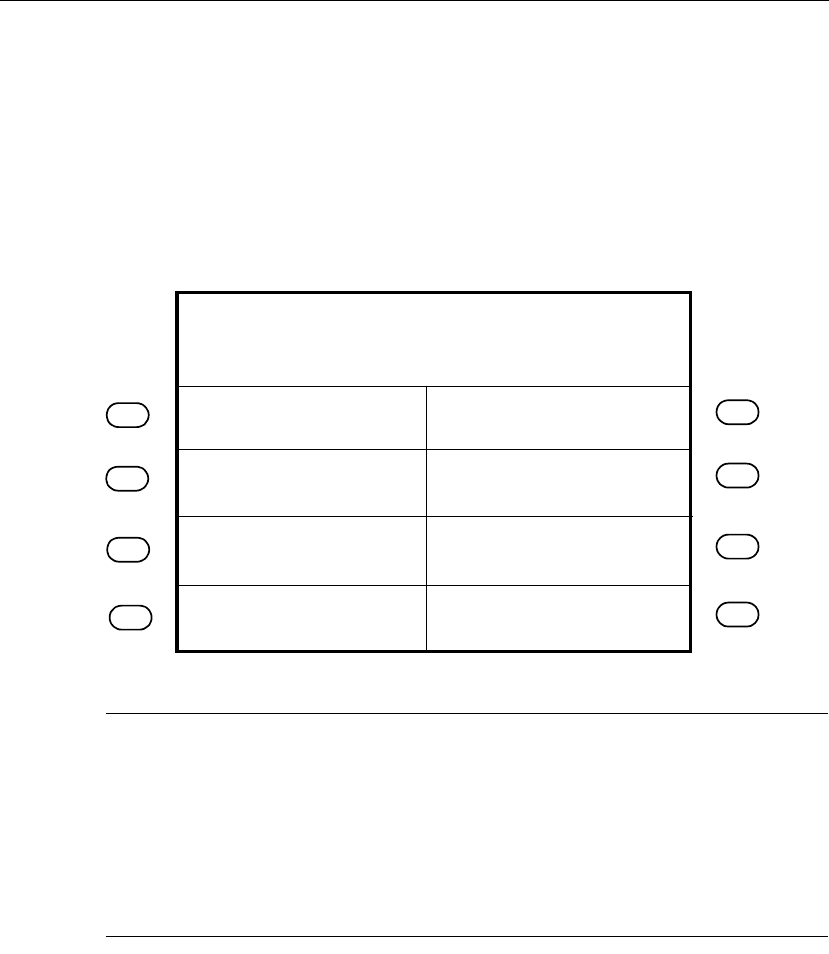
The following figure is a sample of Supervisor Mode:
Note
The difference between Supervisor functions and Employee functions is that the
Supervisor functions allow you to edit any employee data, while the Employee
functions allow employees to perform basic administrative tasks on their own.
Your Series 4000 timeclock can be configured to allow users to perform
Employee functions while in Supervisor Mode. For more information about
Employee functions that can also be performed as Supervisor functions, see
Chapter 2, “Employee Functions.”
On/Off Premises
Add Punch
Delete Punch
Global NH Override
Single NH Override
Fri Aug - 24 - 2001
Supervisor Mode
2:03 PM
Single Home Override

What Are Supervisor Functions?
Series 4000 Badge Timeclock User’s Guide 3-3
The following list shows the Supervisor functions you can perform using the
Series 4000 timeclock. The transaction names are the default names. When setting
up these transactions using the host application software, you can customize the
names.
Note
Your timeclock can only perform the following functions after the soft keys have
been configured using the host application software.
!Add Punch
!Change Password
!Delete Punch
!Display On/Off Premise Employees
!Global Home Employee Restriction Override
!Global Non-Home Employee Restriction Override
!Pay Code Hours Adjustment
!Single Home Employee Restriction Override
!Single Non-Home Employee Restriction Override
!View Employee Information
Note
You need to be careful about performing Supervisor functions that might affect
data that has already been sent to your Payroll.
The remainder of this chapter contains more information about each of these
Supervisor functions.

Chapter 3 Supervisor Functions
3-4 ADP, Inc.
To perform Supervisor functions, you must first access Supervisor Mode. Then,
you can select the desired Supervisor function.
To access Supervisor Mode:
To exit from Supervisor Mode, press ESC.
Note
If the timeclock is idle for 45 seconds without any input from the keypad, it
automatically exits from Supervisor Mode and returns to Employee Mode.
Step Display Action
1 Idle screen Do one of the following:
!Swipe your supervisor badge from top to bottom
and press ENTER.
!Type in your supervisor badge number using the
keypad, and press ENTER.
2 Supervisor Login Type the password (up to 6 digits), and press
ENTER.
3 Supervisor Mode screen Press the desired Supervisor Command soft key.

Performing Supervisor Functions
Series 4000 Badge Timeclock User’s Guide 3-5
Performing Supervisor Functions
This section describes the steps you must follow to perform Supervisor functions
at the Series 4000 timeclock.
Add Punch
Use the Add Punch transaction to add a missing punch for an employee. You can
perform this transaction for 30 days forward or backward from the current date.
The current date is considered day 0.
Note
Midnight (12:00 A.M.) is the first minute of a day. This means that 11:59 P.M. is
thelastminuteofaday.
You can perform this transaction on more employees for the same punch date and
time by entering additional badges after each transaction has been verified and
accepted.
Step Display Action
1 Supervisor Mode screen Press the Add Punch soft key.
2 Edit Date Do one of the following:
!Press ENTER to accept the default date.
!Press CLR, type a new date using mm/dd/yyyy
format, then press ENTER.
3 Edit Time Do one of the following:
!Press ENTER to accept the default date.
!Press CLR, type a 4-digit time using 24-hour
format, then press ENTER.

Chapter 3 Supervisor Functions
3-6 ADP, Inc.
Change Password
Use the Change Password transaction to change the password for a specific
supervisor badge.
4 Enter Badge Do one of the following:
!Swipe the employee badge from top to bottom.
!Type the employee badge number using the
keypad, and press ENTER.
!Press ESC to end the transaction.
Step Display Action
1 Supervisor Mode screen Press the Change Password soft key.
2 Old Password Type the old password for the badge.
3 New Password Type the new password.
4 Verify Password Type the new password a second time.
Step Display Action

Performing Supervisor Functions
Series 4000 Badge Timeclock User’s Guide 3-7
Delete Punch
Use the Delete Punch transaction to delete an improperly entered employee
punch. You can perform this transaction for 30 days forward or backward from the
current date, which is considered Day 0.
You can perform this transaction on more employees for the same punch date and
time by swiping additional badges after each transaction has been verified and
accepted.
Step Display Action
1 Supervisor Mode screen Press the Delete Punch soft key.
2 Edit Date Do one of the following:
!Press ENTER to accept the default date.
!Type the date over the default date using
mm/dd/yyyy format, then press ENTER.
3 Edit Time Do one of the following:
!Press ENTER to accept the default time.
!Type the 4-digit time over the default time using
24-hour format, then press ENTER.
4 Enter Badge Do one of the following:
!Swipe the employee badge from top to bottom.
!Type the employee badge number using the
keypad, and press ENTER.
!Press ESC to end the transaction.

Chapter 3 Supervisor Functions
3-8 ADP, Inc.
Display On/Off Premise Employees
Use the Display On/Off Premise Employees transaction to see a list of employees
who are currently on or off of the premises.
Global Home Employee Restriction Override
Use the Global Home Employee Restriction Override transaction to override
schedule and punch restrictions for home employees when unusual circumstances
arise (such as allowing all employees to punch out early when the company closes
due to a snow storm or power outage). This enables employees to punch when
they normally would not be able to do so.
When a Restriction Override is enabled, a star icon appears on the timeclock
display.
Step Display Action
1 Supervisor Mode screen Press the Display On/Off Premise soft key.
2 On/Off Premises Press the toggle soft keys to select On or Off and
press ENTER.
Step Display Action
1 Supervisor Mode screen Press the Global Home Employee Restriction
Override soft key.
2 Enable/Disable Use the toggle soft keys to select Enable or Disable,
and press ENTER.
3 Duration Type the length of time that the override is in effect
using the hh:mm format, and press ENTER.

Performing Supervisor Functions
Series 4000 Badge Timeclock User’s Guide 3-9
Global Non-Home Employee Restriction Override
Use the Global Non-Home Employee Restriction Override transaction to
temporarily or indefinitely allow all non-home employees to punch at restricted
times. This enables employees to punch when they normally would not be able to
do so. This is useful when unusual circumstances arise such as allowing
employees to punch out early when the company closes due to a snow storm or
power outage.
When a Restriction Override is enabled, a star icon appears on the timeclock
display.
Step Display Action
1 Supervisor Mode screen Press the Global Non-Home Employee Restriction
Override soft key.
2 Enable/Disable Use the toggle soft keys to select Enable or Disable,
and press ENTER.
3 Duration Type the length of time that the override is in effect
using the hh:mm format, and press ENTER.

Chapter 3 Supervisor Functions
3-10 ADP, Inc.
Pay Code Hours Adjustment
Use the Pay Code Hours Adjustment transaction to move hours from one pay code
to another (such as regular time to overtime) for an employee.
Step Display Action
1 Supervisor Mode screen Press the Pay Code Hours Adjustment soft key.
2 Hours Worked Type the hours and press ENTER.
3 Edit Date Do one of the following:
!Press ENTER to accept the default date.
!Press CLR, type a new date using mm/dd/yyyy
format, then press ENTER.
4 Edit Time Type the 4-digit time using 24-hour format, then
press ENTER.
5 Pay Code (Taken) Do one of the following:
!Press ENTER to accept the default pay code.
!Press CLR, type a new pay code, then press
ENTER.
6 Pay Code (Moved to) Do one of the following:
!Press ENTER to accept the default pay code.
!Press CLR, type a new pay code, then press
ENTER.
7 Activity Code (optional) Do one of the following:
!Press ENTER to accept the default activity code.
!Press CLR, type a new activity code, then press
ENTER.
8 Labor Account (optional) Do one of the following:
!Press ENTER to accept the default labor account.
!Press CLR, type a new labor account, then press
ENTER.
9 Enter Badge Do one of the following:
!Swipe the employee badge from top to bottom.
!Type the employee badge number using the
keypad, and press ENTER.

Performing Supervisor Functions
Series 4000 Badge Timeclock User’s Guide 3-11
Single Home Employee Restriction Override
Use the Single Home Employee Restriction Override transaction to override
schedule and punch restrictions for home employees when unusual circumstances
arise (such as allowing a selected employee to start early or leave early). This
enables an employee to punch when they normally would not be able to do so.
In the Number of Credits step, you enter a specific number of times that you want
to allow the employee to be able to punch. This prevents you from having to enter
information for an employee every day when you know ahead of the time that
they are going to need this option for any length of time.
You can perform this transaction on more employees by swiping additional
badges after each transaction has been verified and accepted.
When a Restriction Override is enabled, a star icon appears on the timeclock
display.
Step Display Action
1 Supervisor Mode screen Press the Single Home Employee Restriction
Override soft key.
2 Enter Badge Do one of the following:
!Swipe the employee badge from top to bottom.
!Type the employee badge number using the
keypad, and press ENTER.
!Type the next employee badge number using the
keypad, and press ENTER.
!Press ESC to end the transaction.
3 Number of Credits Type the number of credits (up to 99), and press
ENTER.
Note
If you type a number greater than 99, the Maximum
Field Length Reached message appears. Press CLR,
then type the correct number.

Chapter 3 Supervisor Functions
3-12 ADP, Inc.
Single Non-Home Employee Restriction Override
Use the Single Non-Home Employee Restriction Override transaction to enter a
punch for a non-home employee when there is a Global Restriction in effect. This
enables an employee to punch when they normally would not be able to.
You can perform this transaction on more employees by swiping additional
badges after each transaction has been verified and accepted.
When a Restriction Override is enabled, a star icon appears on the timeclock
display.
View Employee Information
Use the View Employee Information transaction to display all information for a
specific employee, such as in/out status, state (working or at break or meal), last
punch, last schedule, and so on. You use your host application to configure what
data you want to be displayed here.
Step Display Action
1 Supervisor Mode screen Press the Single Non-Home Employee Restriction
Override soft key.
2 Enter Badge Do one of the following:
!Swipe the employee badge from top to bottom.
!Type the employee badge number using the
keypad, and press ENTER.
Step Display Action
1 Idle screen Press the View Employee Information soft key.
2 Enter Badge Do one of the following:
!Swipe the employee badge from top to bottom.
!Type the employee badge number using the
keypad, and press ENTER.
Chapter 4
Maintaining the Timeclock
This chapter contains the following sections:
!Maintenance Basics
!Preventive Maintenance
!Servicing the Timeclock
!What Are the Maintenance Functions?
!Performing Maintenance Functions

Chapter 4 Maintaining the Timeclock
4-2 ADP, Inc.
Maintenance Basics
This section presents basic guidelines for maintaining and servicing the Series
4000 timeclock, including the tools you need, and safety considerations.
Types of Maintenance
There are two types of maintenance you perform on the Series 4000 timeclock:
!Preventive maintenance—Includes basic cleaning of the timeclock, and
running diagnostic tests and reports using Maintenance Mode functions.
!Servicing procedures—Includes ordering and replacing parts, testing the
timeclock, and performing basic configuration at the timeclock.
Required Tools
You need the following tools to service and maintain the Series 4000 timeclock:
!Screwdrivers: Phillips #0, #1, #2; and straight blade 1/8 inch and 1/4 inch
!5-32 security-head Allen wrench
!A nonmetallic pointed tool
!Soft, clean, lint-free cleaning cloths
!Spray bottle of general-purpose glass cleaner
!Isopropyl alcohol
!ADP Field Service Anti-Static Kit
!Wire cutters/strippers

Maintenance Basics
Series 4000 Badge Timeclock User’s Guide 4-3
Safety Considerations
The Series 4000 timeclock is approved by Underwriter’s Laboratories (UL), the
Canadian Standards Association (CSA), and the Federal Communications
Commission (FCC), and ships from the factory in a safe condition.
Warning
This chapter contains information that you must follow to ensure safe operation
and maintenance of the timeclock. Failure to follow a warning statement can
result in personal injury.
Handling Static-Sensitive Components
Many assemblies in the Series 4000 timeclock have static-sensitive components.
Static electricity can cause hardware components to fail. Use the ADP Field
Service Anti-Static Kit (part number 3600166-001) when handling static-sensitive
assemblies.
You can damage components if you do not take the following precautions:
!When handling a static sensitive assembly for any reason, first put on the
Anti-Static Kit’s wrist strap. Wrap the conductive wrist strap around your
wrist so that it is comfortable, and secure the fastener. Be sure the other end of
the strap is grounded.
!When you finish handling the assembly, replace it in the Series 4000
timeclock, or place it on a grounded conductive surface.

Chapter 4 Maintaining the Timeclock
4-4 ADP, Inc.
Obtaining Replacement Parts
The following listing shows the parts that you can order for the Series 4000
timeclock. To order a part, contact your TLM Representative.
Part Number Description
8900052-001 Anchors, 3
8601763-001 Backup battery
9600015-001 Badge reader cover
6800134-001 Badges, maintenance
6800133-001 Badges, supervisor
9600020-001 Hinge
9000104-001 Hinge screws, 2
8601824-001 Internal AC outlet
9600016-001 I/O panel
9000151-001 Mounting screws, 3
7200200-001 Power cord, 6-foot
7200201-001 Power cord, 12-inch
8400408-001 Power cord strain relief clip
9100200-001 Power cord strain relief nuts, 2
9000203-001 Power cord strain relief screws, 2
8900018-001 Security wrench
8400428-001 Square cable plate
9100104-001 Square cable nuts, 2
7800102-001 Transformer
8400433-001 Transformer holder

Preventive Maintenance
Series 4000 Badge Timeclock User’s Guide 4-5
Preventive Maintenance
The Series 4000 timeclock requires periodic preventive maintenance to ensure
trouble-free operation. ADP recommends that you perform preventive
maintenance at least once a year, depending on the environment in which the
timeclock is used.
Cleaning the Timeclock
Keep the Series 4000 timeclock case and badge reader clean to prevent dirt and
grease from obscuring the LCD display or getting inside the badge reader.
To clean the timeclock’s case and keyboard:
1. Using a soft, lint-free cloth, and a spray bottle of glass cleaner, clean the
outside of the Series 4000 timeclock’s cover and case. Do not spray the
cleaner inside the timeclock’s case. When cleaning the timeclock’s case, spray
the cleaner on the cloth—do not spray the cleaner directly on the timeclock.
2. Clean the polycarbonate lens that covers the timeclock’s display.
Do not use steel wool or any other abrasives, or solvents such as alcohol, benzene,
or acetone, as they can damage the timeclock.
To clean the badge reader:
1. Fold a paper towel over an inactive badge.
2. Spray the towel gently with a glass cleaner.
3. Swipe the badge several times in the badge reader.

Chapter 4 Maintaining the Timeclock
4-6 ADP, Inc.
About the Lithium and Lead Acid Batteries
This section describes the two types of batteries used by the Series 4000
timeclock.
Each Series 4000 timeclock is equipped with a lithium battery. As an option, you
can also install a lead acid battery for backup power in the event of a power
outage.
Note
Be sure to check all local and national regulations pertaining to the proper storage
and disposal of batteries.
Lithium Battery
The lithium battery is a 3 VDC battery that powers the timeclock’s internal real-
time clock if external power is lost. You cannot perform any timeclock operations
while the timeclock is operating on lithium battery backup.
You should replace the lithium battery when it is 3 years old or if the date and time
do not reset correctly after a power failure.
To replace the lithium battery, do the following:
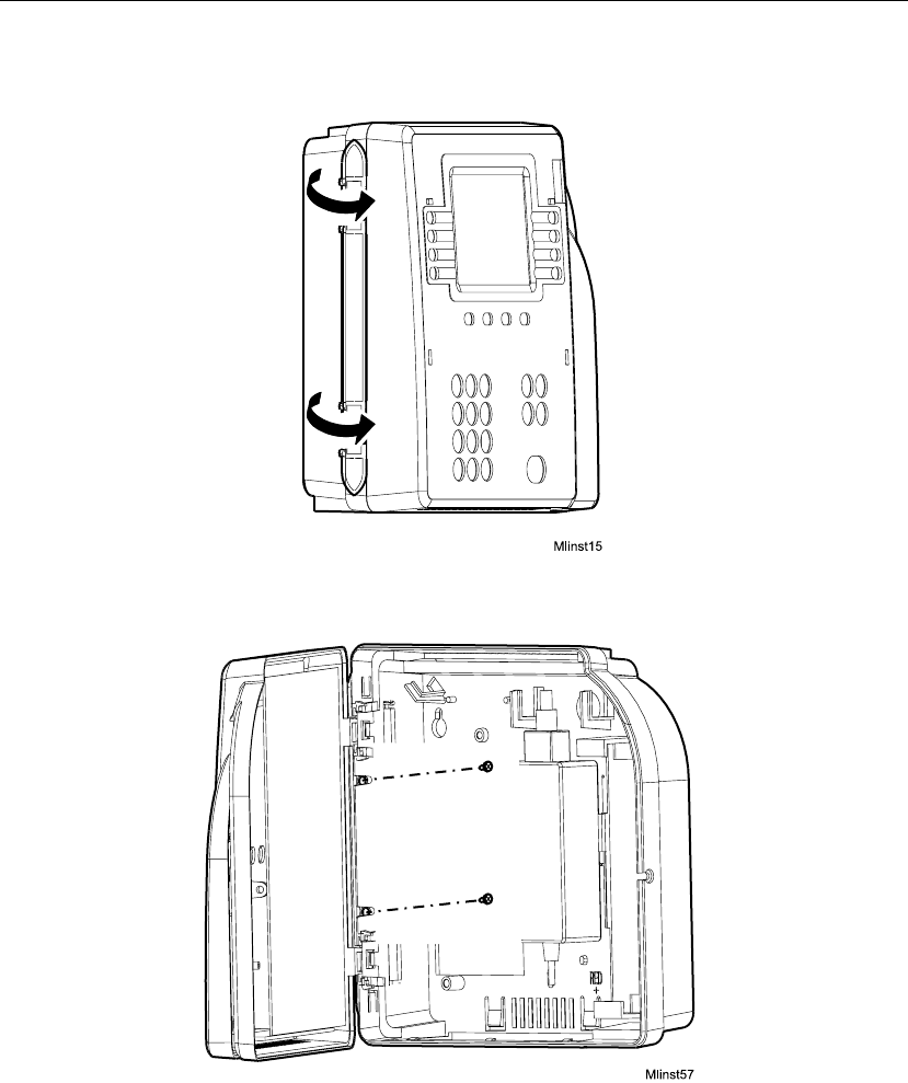
1. Open the timeclock’s cover by using the security wrench to loosen the
security screw on the right side of the timeclock.
2. Use a nonmetallic pointed tool to remove the lithium battery.
3. Install the new lithium battery.
4. Close and lock the timeclock cover using the security wrench.

Preventive Maintenance
Series 4000 Badge Timeclock User’s Guide 4-7
Lead Acid Battery
The lead acid battery is an optional 12-VDC backup battery that you can order
separately. The lead acid battery provides up to two hours of full functionality in
the event of a power failure, including support of:
!Full LCD display (backlight automatically dimmed)
!Badge reader
!Keypad entries
!Ethernet communications
You should replace the backup battery when it is 4 years old. When you order a
new backup battery, you also receive an installation guide.
Note
It takes 24 hours for the Series 4000 timeclock to recharge the backup battery after
the backup battery has been completely depleted.
Running Diagnostic Tests and Reports
You can run diagnostic tests and reports to test parts of the timeclock or to get
specific information about the timeclock. For more information about diagnostic
tests and reports, see the “What Are the Maintenance Functions?” section
beginning on page 4-43.

Chapter 4 Maintaining the Timeclock
4-8 ADP, Inc.
Servicing the Timeclock
Servicing the Series 4000 timeclock consists mainly of checking status,
configuring the timeclock, testing components, and removing and replacing
malfunctioning components of the timeclock.
Depending on the nature of the problem you are having with the timeclock, you
will do one of the following:
!Send the front cover assembly back to ADP, Inc. Do this if there is
something wrong with the main board of the timeclock, or you and your TLM
Representative cannot readily identify the problem with the timeclock. See
the “Returning the Cover Assembly to ADP” section on page 4-10 in this
chapter for detailed instructions.
!Obtain a replacement part. Examples of replacement parts are the
transformer, backup battery, and badge reader cover. See the “Replacing the
Backup Battery Charger Board” section on page 4-24 in this chapter for a
complete list of parts and the procedure for ordering parts.
Caution
Before servicing the Series 4000 timeclock, save its data by using your host
application software to collect the data. For more information about collecting
data, see the “Using the Host Application Software to Collect Data” section on
page 4-10.
Servicing the Timeclock
Series 4000 Badge Timeclock User’s Guide 4-9
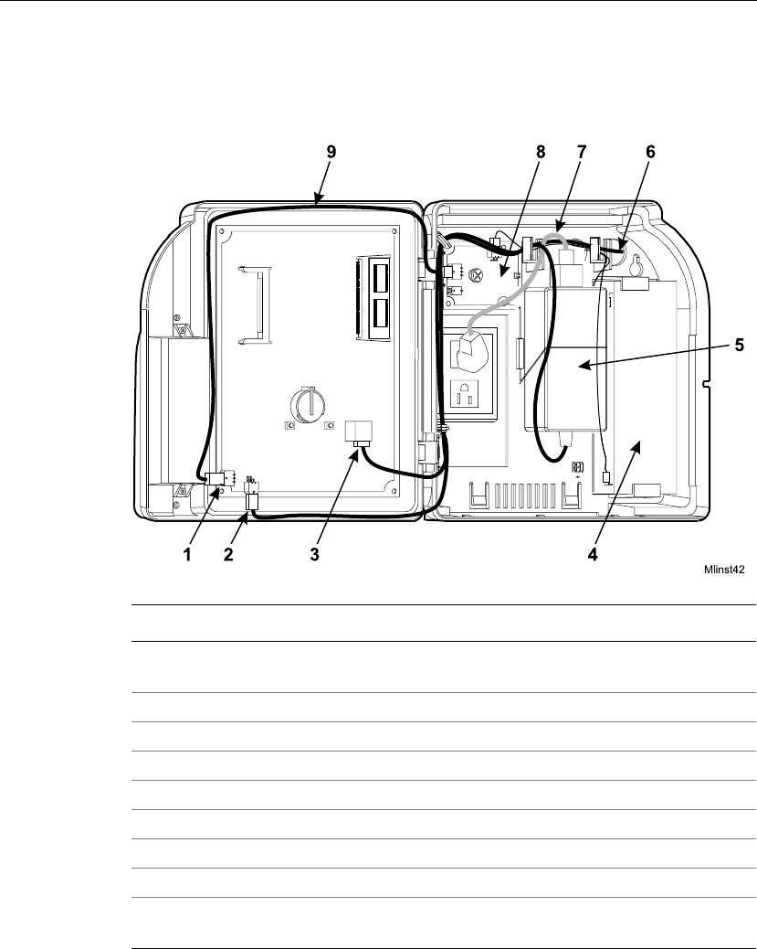
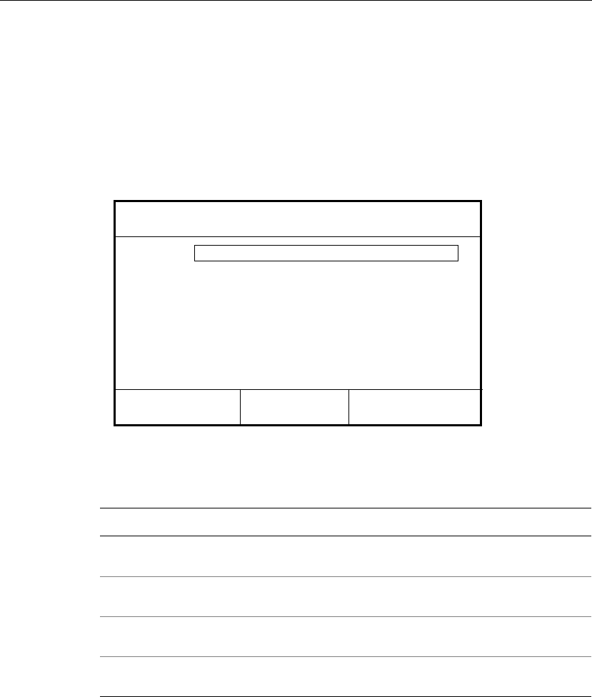
Interior of Fully-Assembled Timeclock
The following figure shows the interior of the Series 4000 timeclock:
Number Description
1 Battery charger board connection to the main board (if the backup
battery is installed)
2 Transformer connection to main board
3 Ethernet connection to main board
4 Backup battery (optional)
5 Transformer
6 Ethernet cable (shown run through the wall and into the timeclock)
7 AC power cable
8 Battery charger board (if the backup battery is installed)
9 Cables for the transformer and battery charger board (optional) routed
to their connection points on the main board (see numbers 1 and 2)

Chapter 4 Maintaining the Timeclock
4-10 ADP, Inc.
Returning the Cover Assembly to ADP
If the mainboard of the Series 4000 timeclock is not operating properly or you and
your TLM Representative cannot identify a problem with the timeclock, you need
to return the front cover assembly to ADP for repair or replacement.
The front cover assembly includes the following major components:
!Main board
!Badge reader and cover
!DC power supply
!Keypad
!Keypad membrane
!Liquid crystal display (LCD)
Using the Host Application Software to Collect Data
Before you remove the front cover, use your host application software to collect
all data.
If your host application is eTIME, you use its data collection timeclock
communication feature (Commlink application) to collect data. For more
information about this process, see the eTIME System Manager Guide and the
eTIME online Help.
If your host application is Enterprise eTIME, you use Data Collection Manager
(DCM) to collect data. For more information about this process, see the DCM
System Administrator’s Guide and the DCM online Help.
Servicing the Timeclock
Series 4000 Badge Timeclock User’s Guide 4-11
Removing the Cover Assembly from the Timeclock
To remove the front cover, you must disconnect the timeclock from its power
source. For example, you may have to remove and replace the timeclock’s lithium
battery, or replace the timeclock itself.
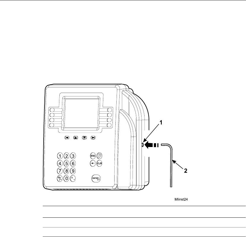
1. Open the timeclock’s cover by using the security wrench to loosen the
security screw on the right side of the timeclock.
2. Disconnect the transformer in the timeclock from the AC power source.
Depending on how you installed the timeclock, do one of the following:
!Unplug the power cord from an AC outlet external to the timeclock.
!If the timeclock is mounted over an AC outlet, unplug the power cord
from that outlet.
!If you used the internal AC outlet, unplug the power cord from the
internal outlet.
Number Description
1 Security screw
2 Security wrench
Chapter 4 Maintaining the Timeclock
4-12 ADP, Inc.
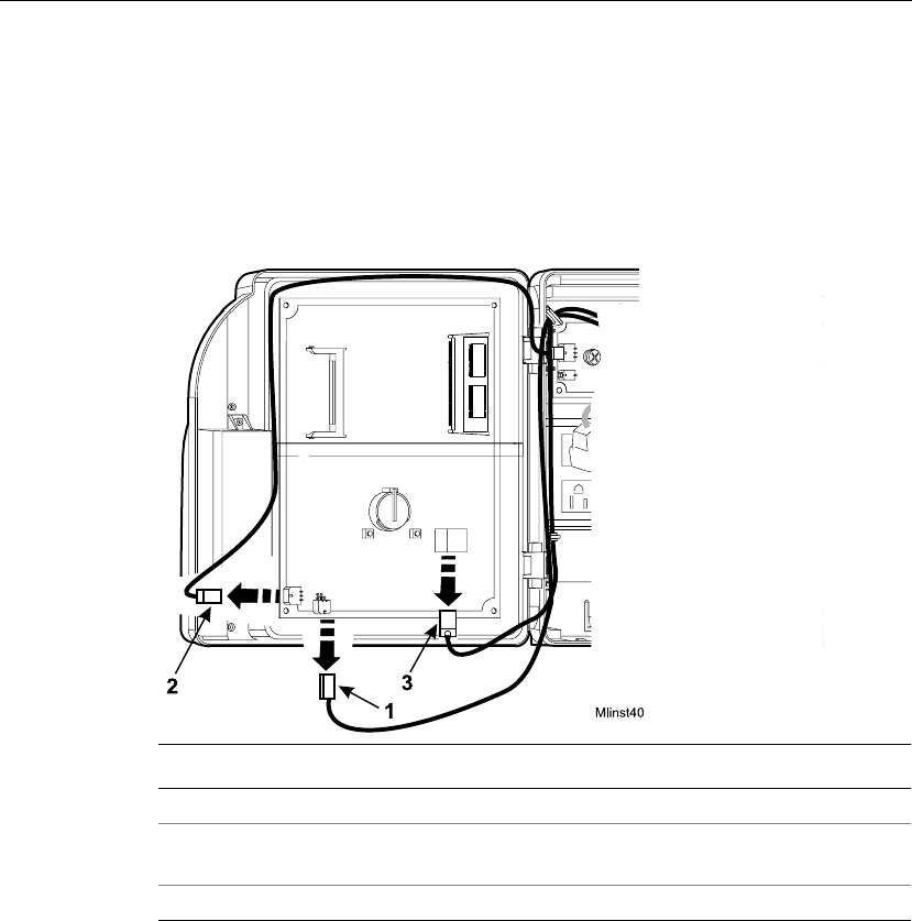
3. Disconnect the following cables from the main board in the order shown.
Refer to the following illustration:
!Transformer cable
!Backup battery cable (if the backup battery is installed)
!Ethernet cable
Number Description
1 Disconnecting the transformer from the main board
2 Disconnecting the battery charger board from the main board (if you
installed the backup battery)
3 Disconnecting the Ethernet cable from the main board
Servicing the Timeclock
Series 4000 Badge Timeclock User’s Guide 4-13
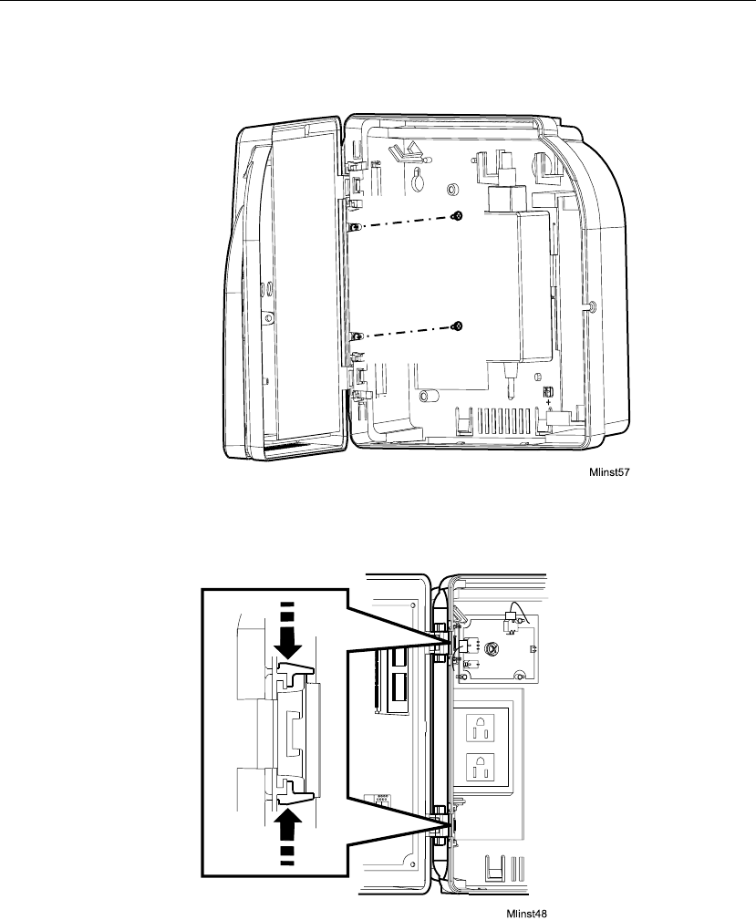
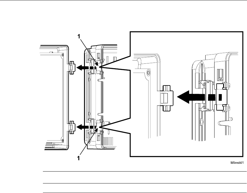
4. Locate and remove the two screws on the left side of the base. See the
following illustration. Keep the screws in a safe place.
5. While supporting the cover with one hand, squeeze the two clips shown in the
following illustration to release the hinge clip holding the cover in place.
Chapter 4 Maintaining the Timeclock
4-14 ADP, Inc.
6. Separate the cover from the base.
Returning the Cover Assembly
When you return the cover assembly to ADP for any reason, you must use the
original ADP carton in which it was shipped.
Number Description
1 Recessed areas in the base where the hinges were seated
Servicing the Timeclock
Series 4000 Badge Timeclock User’s Guide 4-15
Attaching the Cover Assemby to the Timeclock
1. Release the plastic hinge clip by squeezing the retainers at each hinge
position. You can squeeze each retainer one at a time or simultaneously until
you feel the clip release.
2. Rotate the hinge clip to the left.
Chapter 4 Maintaining the Timeclock
4-16 ADP, Inc.
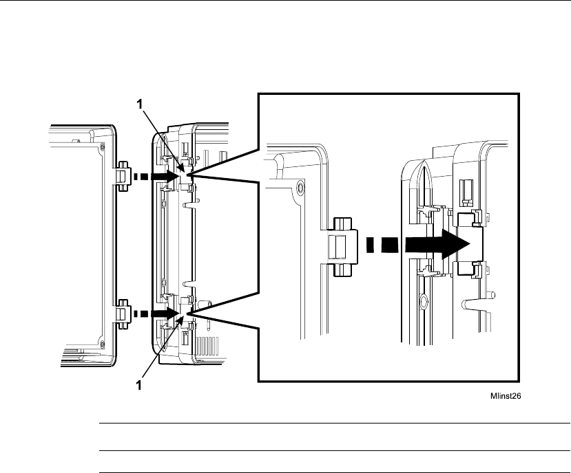
3. Fit the two hinges on the cover into the corresponding areas molded in the
base.
Number Description
1 Recessed areas in the timeclock base for seating the hinges
Servicing the Timeclock
Series 4000 Badge Timeclock User’s Guide 4-17
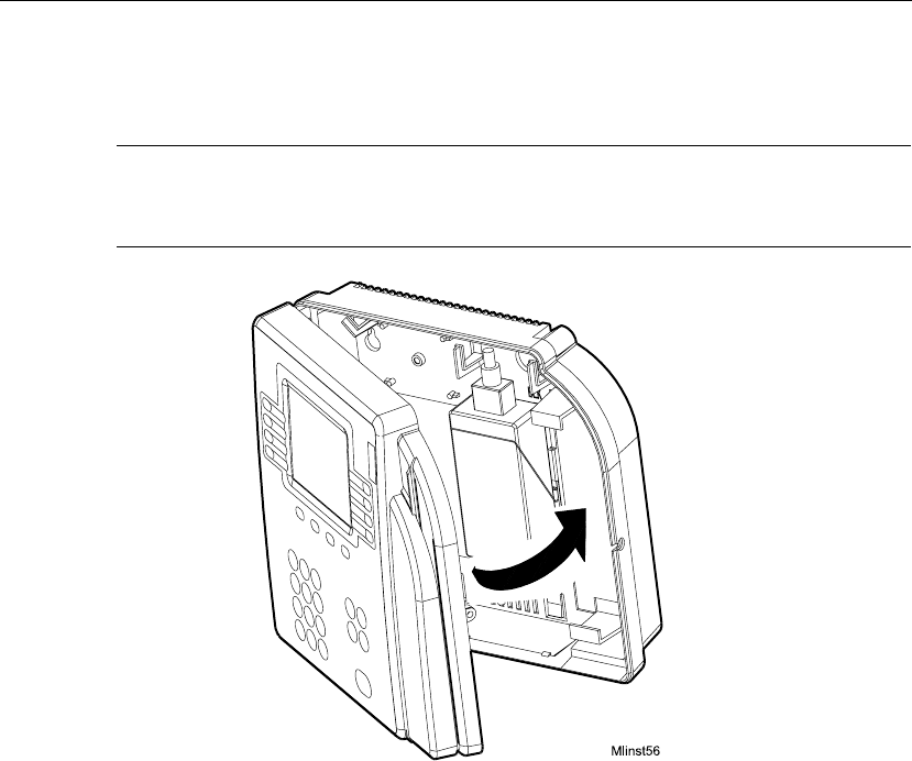
4. Carefully close the cover of the timeclock, making sure that the two hinges
remain properly seated in place.
Caution
After the cover is closed, continue to hold it securely in place as you perform the
next step.
Chapter 4 Maintaining the Timeclock
4-18 ADP, Inc.
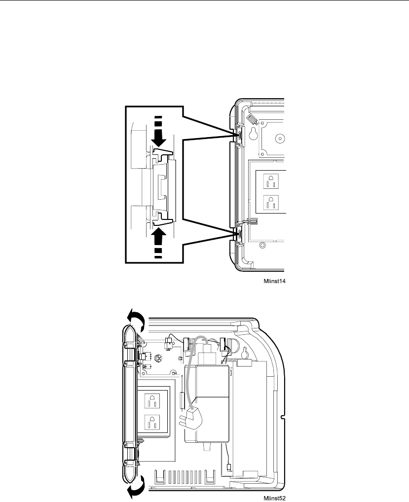
5. Rotate the hinge clip forward until it snaps into place.
6. Open the cover and install the two small, flat (not pointed) screws to secure
the hinge clip, as shown in the following illustration.

Servicing the Timeclock
Series 4000 Badge Timeclock User’s Guide 4-19
7. Reconnect the cables inside the timeclock and plug in the power cable. If
necessary, refer to the Series 4000 Badge Timeclock Installation Guide that
you received with your timeclock.
When the Series 4000 timeclock is initialized and the Communication Setting
screen appears, go to “Performing Basic Configuration at the Series 4000
Timeclock” on page 4-20 to perform basic configuration at the timeclock.
Chapter 4 Maintaining the Timeclock
4-20 ADP, Inc.
Performing Basic Configuration at the Series 4000 Timeclock
Whenever you restore the Series 4000 timeclock to the factory defaults, you must
complete the basic configuration settings on the timeclock before you can restore
the timeclock’s overall configuration from the host application.
When the Series 4000 timeclock is first powered on and initializes (“boots up”),
the Communications Setting screen appears:
1. On the Communication Setting screen, complete the following fields, with
the help of your network administrator:
Settings Description
Device ID Enter an ID number (at least six digits) for the timeclock. The host
application uses this number to identify the timeclock.
IP Address Enter the IP address, including the periods, assigned to the timeclock
by your system administrator.
Gateway Enter the IP address, including the periods, of the default device that
forwards data to the host application. This field holds up to 15 digits.
Subnet Mask Specify a number that identifies a subnetwork so that an IP address
can be found on a LAN. This field holds up to 15 digits.
Device ID
Changing comm settings causes a reboot!
Gateway
IP Address
Subnet Mask

Servicing the Timeclock
Series 4000 Badge Timeclock User’s Guide 4-21
2. Press ENTER at the last prompt. The timeclock reboots itself so that the new
communications settings take effect, and then the idle screen appears:
3. Swipe the Maintenance badge that came with the Series 4000 timeclock (the
badge has an “M” on the front). To do this, hold the badge so that the bar code
is positioned on the back left edge and swipe the badge up or down through
the reader’s slot. The Maintenance Mode menu screen appears:
Fri 17–Aug–2001
2:03 PM
Comm Setting
Display Setting
Audio Setting
Symbology Setting
Date/Time Setting
Maintenance Mode
2:03 PM
FACTORY DEFAULT
Restart
More...
Fri 17–Aug–2001
Date/Time Setting
2:03
Date/Time Setting
Audio Setting

Chapter 4 Maintaining the Timeclock
4-22 ADP, Inc.
4. To change the current appearance of text on the screen, press the Display
Setting soft key and complete the following fields. To quickly set a field to its
minimum value, press CLR.
5. Press ENTER to save the settings and return to the Maintenance Mode screen.
6. To change, enable, or disable the key click, or adjust the beeper volume, press
the Audio Setting soft key and complete the following fields:
7. Press ENTER to save the settings and return to the Maintenance Mode screen.
8. Press the Date/Time Setting soft key and enter the current date and time
using the indicated format.
Settings Description
Contrast Use the + and - keys indicated at the bottom of the screen to
increase or decrease the degree of difference between light and dark
extremes of color on the timeclock’s display. The minimum value is
16; the maximum value is 22.
Brightness Use the + and - keys indicated at the bottom of the screen to
increase and decrease the brightness of the timeclock display.
Settings Description
Beeper volume Use the + and - keys indicated at the bottom of the screen to increase
and decrease the degree of beeper volume. The minimum value is 1;
the maximum value is 7.
Key click Use the Off and On keys indicated at the bottom of the screen to
enable or disable the key click sound. The Off/On choices appear
when you position the cursor in this field.
Settings Description
Date (mm/dd/yyyy) Enter the current month, day, and year. For the year, enter all
four digits. Do not enter the slashes.
Time (24 hour) Enter the current time of day in 24-hour format. Do not enter
the colon. For example, enter 1730.
Servicing the Timeclock
Series 4000 Badge Timeclock User’s Guide 4-23
9. Press ENTER to save the settings and return to the Maintenance Mode screen.
10. Press the Symbology Setting soft key and use the On and Off soft keys to
indicate the type of bar codes used on your employees’ badges. This allows
the timeclock to read the badges properly.
11. Press ENTER to save the settings and return to the Maintenance Mode screen.
12. To create a password that allows access to the Maintenance Mode screen in
the future, press the More soft key and then the Change Password soft key.
Complete the following fields:
13. Press ENTER to save the password and return to the Maintenance Mode
screen.
14. Press ESC to exit Maintenance Mode and return to the idle screen.
Settings Description
Old Password Enter the old password, if there was one.
New Password Enter the new password.
Verify Password Enter the new password again to verify that you entered it
correctly.
Code 3-of-9:
Symbology Setting
On Off
Off
UPC-A: Off
12-of-5: On
Code 128: Off
UPC-E: Off
EAN-13: Off
EAN-8: Off
Codabar: Off
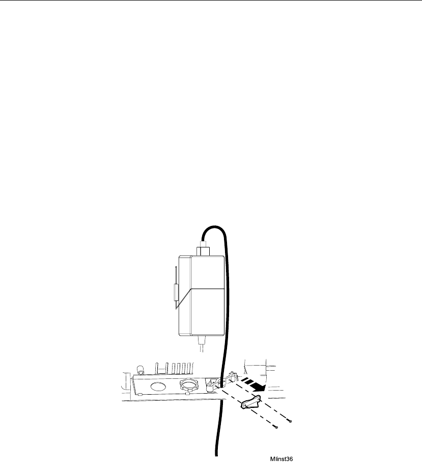
Chapter 4 Maintaining the Timeclock
4-24 ADP, Inc.
Replacing the Backup Battery Charger Board
1. Before you begin, collect data from the timeclock using your host application
software. For more information, see the “Using the Host Application
Software to Collect Data” section on page 4-10.
2. Open the timeclock’s cover by using the security wrench to loosen the
security screw on the right side of the timeclock.
3. To disconnect and remove the battery charger board, you must first remove
the transformer. Do the following:
a. Unplug the transformer from the AC power source. If you plugged the
timeclock into an external outlet, disassemble the strain relief clip at the
power cord’s point of entry into the timeclock. See the following
illustration.
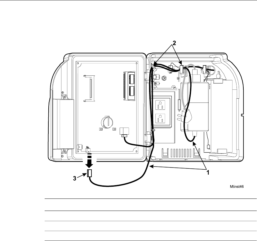
Servicing the Timeclock
Series 4000 Badge Timeclock User’s Guide 4-25
b. Unplug the power cord from the transformer.
c. Disconnect the transformer cable from the timeclock’s main board.
d. Trace the wire back to the transformer, freeing it from the hooks molded
into the base of the timeclock.
Number Description
1 Transformer cable
2 Hooks holding the cable in place
3 Transformer connection to the main board (DC power)
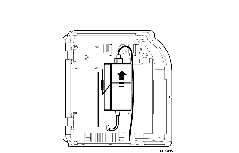
Chapter 4 Maintaining the Timeclock
4-26 ADP, Inc.
e. Lift the transformer from behind the wire clip, and out of the timeclock.
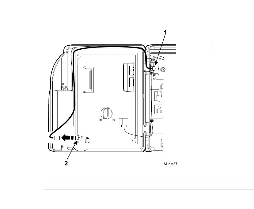
Servicing the Timeclock
Series 4000 Badge Timeclock User’s Guide 4-27
4. Disconnect the battery charger board from the timeclock’s main board.
5. Trace the wires back to the charger board.
Number Description
1 Battery charger board cable
2 Charger board connection to the main board
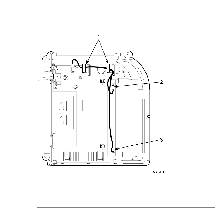
Chapter 4 Maintaining the Timeclock
4-28 ADP, Inc.
6. Disconnect the battery charger board from the positive and negative terminals
of the backup battery.
Number Description
1 Hooks molded into the base
2 Negative terminal connection
3 Positive terminal connection
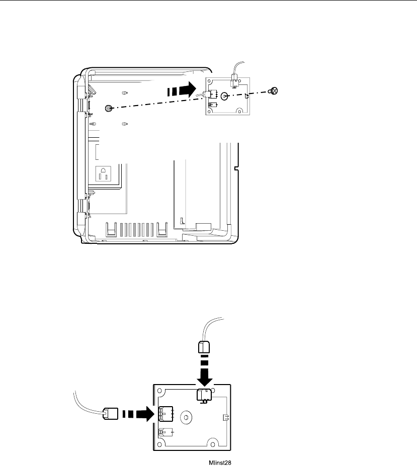
Servicing the Timeclock
Series 4000 Badge Timeclock User’s Guide 4-29
7. Loosen the screw in the center of the battery charger board and remove the
board from the timeclock.
8. Unplug the cables from the connectors on the charger board.
9. Plug the cables into the connectors on the new charger board. Match the ends
of each cable with the appropriate pin connector on the charger board.
10. Re-install the battery charger board into the timeclock.
11. Reconnect the wires from the charger board to the battery terminals.
Mlinst38
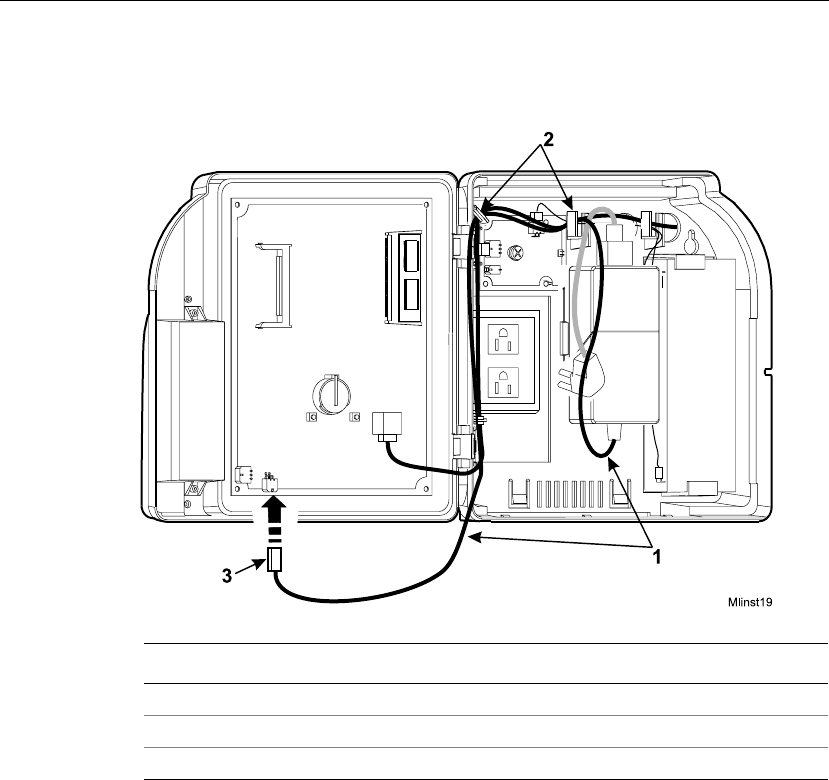
Chapter 4 Maintaining the Timeclock
4-30 ADP, Inc.
12. Position the transformer back into place behind the wire clip, route the cable
back to its connection on the main board, and plug in the cable.
Number Description
1 Transformer cable
2 Hooks for routing the cable
3 Transformer connection to the main board (DC power)
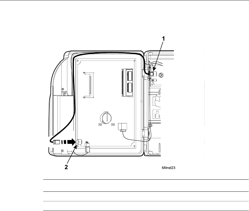
Servicing the Timeclock
Series 4000 Badge Timeclock User’s Guide 4-31
13. Route the charger board cable back to its connection on the main board and
plug in the cable.
14. Plug the transformer back into the AC power source.
15. Test the battery backup by watching the amber LED on the front of the Series
4000 timeclock. When you remove AC power while the battery backup option
is installed, the amber LED flashes on and off, indicating that the timeclock is
being powered by battery. When you restore AC power, the LED lights
continuously.
Number Description
1 Battery charger board cable
2 Charger board connection to the main board
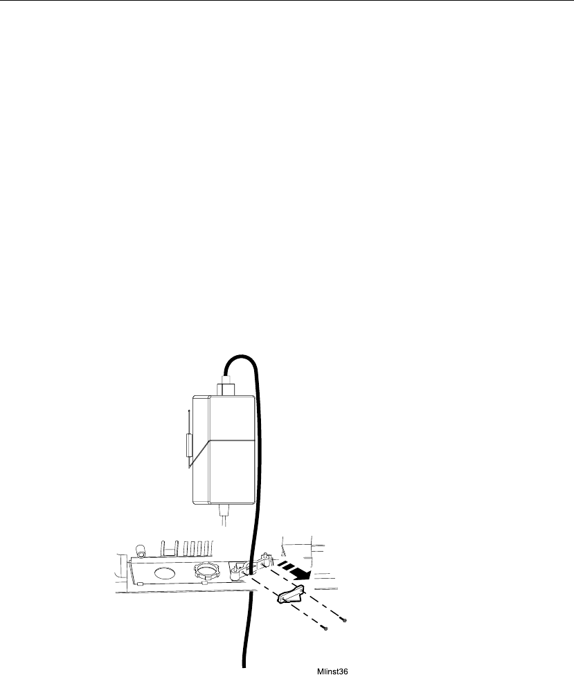
Chapter 4 Maintaining the Timeclock
4-32 ADP, Inc.
Adjusting the Width of the Badge Reader Slot
Removing the Reader Spacers
If you did not remove the spacers before you installed the Series 4000 timeclock,
you need to perform the following procedure to remove them from the back of the
timeclock:
1. Before you begin, collect data from the timeclock using your host application
software. For more information, see the “Using the Host Application
Software to Collect Data” section in this chapter.
2. Open the timeclock’s cover by using the security wrench to loosen the
security screw on the right side of the timeclock.
3. Unplug the transformer from the AC power source. If you plugged the
timeclock into an external outlet, disassemble the strain relief clip at the
power cord’s point of entry into the timeclock.
4. Unplug the power cord from the transformer.
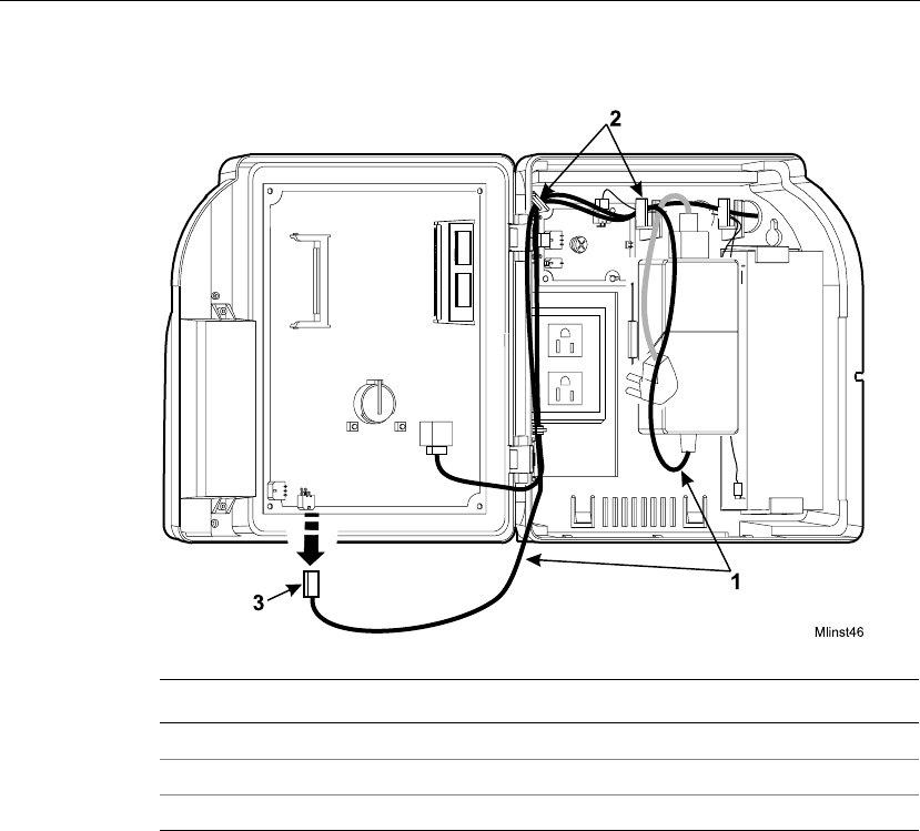
Servicing the Timeclock
Series 4000 Badge Timeclock User’s Guide 4-33
5. Disconnect the transformer cable from the timeclock’s main board.
6. Trace the wire back to the transformer, freeing it from the hooks molded into
the base of the timeclock.
Number Description
1 Transformer cable
2 Hooks for routing the cable
3 Transformer connection to the main board (DC power)
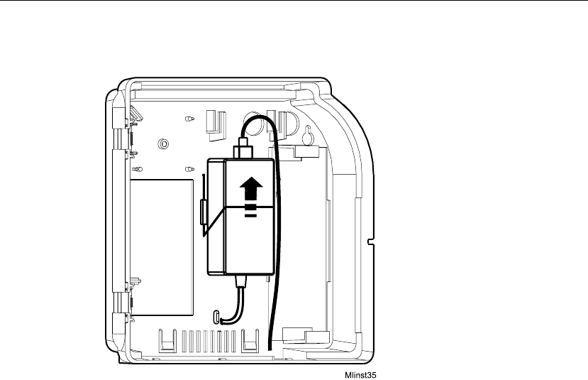
Chapter 4 Maintaining the Timeclock
4-34 ADP, Inc.
7. Lift the transformer from behind the wire clip and out of the timeclock.
8. Unplug the AC power cord from the top of the transformer and lay the
transformer in a safe place.
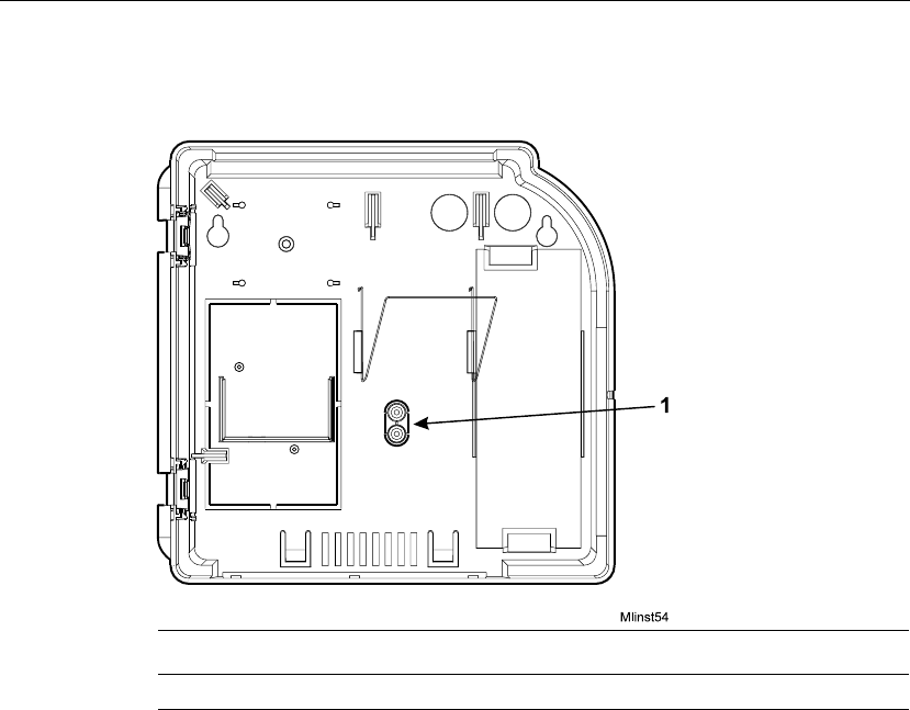
Servicing the Timeclock
Series 4000 Badge Timeclock User’s Guide 4-35
9. Use a utility knife to remove the two round spacers from the back of the
timeclock where the transformer had been positioned.
10. Install the transformer back in the timeclock as follows:
a. Position the transformer behind the wire clip in the timeclock.
b. Route the transformer cable to its connection point on the main board and
plug the connector in.
c. Plug the transformer back into the AC outlet. If you are plugging the
timeclock into an external AC outlet, route the power cord out of the
timeclock and re-assemble the strain relief clip to secure the cord.
11. Close and lock the timeclock cover using the security wrench.
Number Description
1 Badge reader spacers molded into the base.
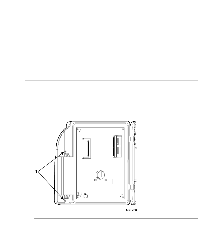
Chapter 4 Maintaining the Timeclock
4-36 ADP, Inc.
Installing the Reader Spacers
You need to widen the badge reader slot if the badges your employees use are
more than .125 in (3.175 mm) thick. To widen the slot, you install two reader
spacers that come molded into the base of the timeclock.
Note
If you did not remove the spacers before you installed the Series 4000 timeclock,
you will need to remove them as explained in “Removing the Reader Spacers” on
page 4-32.
1. Open the timeclock’s cover by using the security wrench to loosen the
security screw on the right side of the timeclock.
2. Use a Phillips screwdriver to loosen the two captive screws inside the
timeclock cover that hold the badge reader cover in place.
Number Description
1 Screws that hold the badge reader cover in place
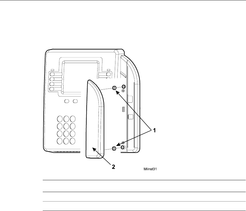
Servicing the Timeclock
Series 4000 Badge Timeclock User’s Guide 4-37
3. On the outside of the timeclock cover, press the two spacers onto the tops of
the channels that hold the screws for the reader cover.
4. Position the reader cover back into place and tighten the two screws.
Number Description
1 Badge reader spacers
2 Badge reader cover
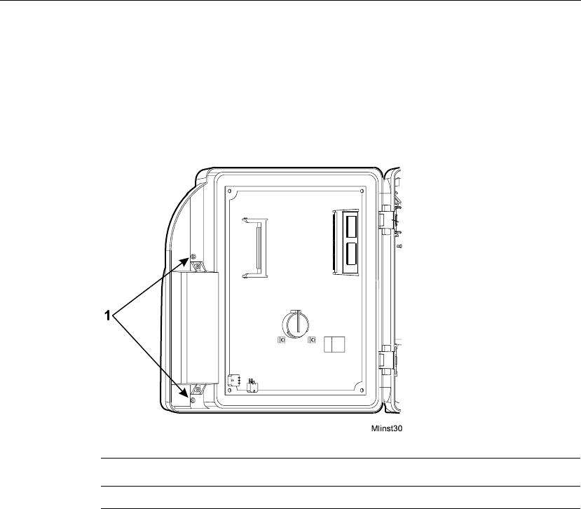
Chapter 4 Maintaining the Timeclock
4-38 ADP, Inc.
Replacing the Badge Reader Cover
1. Open the timeclock’s cover by using the security wrench to loosen the
security screw on the right side of the timeclock.
2. Use a Phillips screwdriver to loosen the two captive screws inside the
timeclock cover, that hold the badge reader cover in place.
Number Description
1 Screws that hold the badge reader cover in place
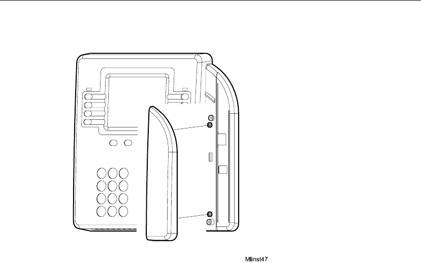
Servicing the Timeclock
Series 4000 Badge Timeclock User’s Guide 4-39
3. Position the new reader cover into place and tighten the two screws.
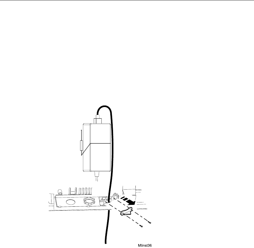
Chapter 4 Maintaining the Timeclock
4-40 ADP, Inc.
Replacing the AC Power Supply (transformer)
1. Before you begin, collect data from the timeclock using your host application
software. For more information, see the “Using the Host Application
Software to Collect Data” section in this chapter.
2. Open the timeclock’s cover by using the security wrench to loosen the
security screw on the right side of the timeclock.
3. Unplug the transformer from the AC power source. If you plugged the
timeclock into an external outlet, disassemble the strain relief clip at the
power cord’s point of entry into the timeclock.
4. Unplug the power cord from the transformer.

Servicing the Timeclock
Series 4000 Badge Timeclock User’s Guide 4-41
5. Disconnect the transformer cable from the timeclock’s main board.
6. Trace the wire back to the transformer, freeing it from the hooks molded into
the base of the timeclock.
Number Description
1 Transformer cable
2 Hooks for routing the cable
3 Transformer connection to the main board (DC power)
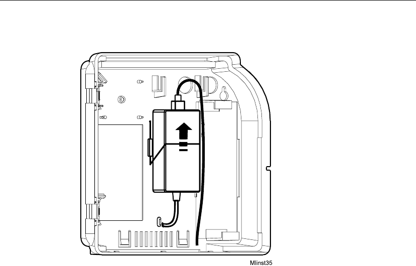
Chapter 4 Maintaining the Timeclock
4-42 ADP, Inc.
7. Lift the transformer from behind the wire clip and out of the timeclock.
8. Unplug the AC power cable from the top of the transformer.
9. Install the new transformer as follows:
a. Plug the AC power cord into the top of the transformer.
b. Position the transformer behind the wire clip in the timeclock.
c. Route the transformer cable to its connection point on the main board and
plug in the connector.
d. Plug the transformer back into the AC outlet. If you are plugging the
timeclock into an external AC outlet, route the power cord out of the
timeclock and re-assemble the strain relief clip to secure the cord.
10. Close and lock the timeclock cover using the security wrench.
What Are the Maintenance Functions?
Series 4000 Badge Timeclock User’s Guide 4-43
What Are the Maintenance Functions?
Maintenance Mode allows you to display technical information about the
timeclock, perform configuration functions, and execute the diagnostic tests. The
diagnostic tests are extremely useful when troubleshooting hardware
malfunctions.
The following figure is a sample of Maintenance Mode:
Note
You can access Maintenance Mode only if you are authorized to use a
Maintenance badge at the Series 4000 timeclock.
Comm Setting
Display Setting
Audio Setting
Symbology Setting
Restart
Date/Time Setting More...
Fri Aug - 24 - 2001
Maintenance Mode
2:03 PM
FACTORY DEFAULT

Chapter 4 Maintaining the Timeclock
4-44 ADP, Inc.
The following list shows the Maintenance functions that you can perform using
the Series 4000 timeclock. The remainder of this chapter contains more
information about each of these functions.
Settings
!Audio Setting (basic configuration)
!Communication Setting (basic configuration)
!Date/Time Setting (basic configuration)
!Display Setting (basic configuration)
!Symbology Setting (basic configuration)
Reports
!Database Report
!Device Status Report
!Ethernet Report
!File System Report
!Memory Report
!Readers Report
Diagnostic Tests
!Badge Test
!Beeper Test
!Display Test
!Keypad Test
!LED Test
!Sequential Tests
Miscellaneous
!Change Password
!FACTORY DEFAULT
!Delete All Punches
!Restart

What Are the Maintenance Functions?
Series 4000 Badge Timeclock User’s Guide 4-45
To perform Maintenance functions, you must first access Maintenance Mode.
Then, you can select the desired Maintenance command.
Note
The first time that you power up the Series 4000 timeclock, the Communication
Settings screen will appear. For more information about what to enter in
communication settings, see the “Communication Setting (basic configuration),”
section in this chapter.
To access Maintenance Mode:
To exit from Maintenance Mode, press ESC.
Note
If the timeclock is idle for 45 seconds without any input from the keypad, it
automatically exits Maintenance Mode and returns to Employee Mode.
Step Display Action
1 Idle screen Swipe the Maintenance badge from top to bottom.
2 Maintenance Login Type the password (up to 6 digits), and press
ENTER.
If you enter the wrong password, an error message
appears. Press CLR to clear the screen, then type the
password again.
3 Maintenance Mode idle
screen Press the desired Maintenance Command soft key.

Chapter 4 Maintaining the Timeclock
4-46 ADP, Inc.
Performing Maintenance Functions
This section presents brief descriptions of Maintenance functions, and instructions
about how to perform them.
Audio Setting (basic configuration)
Use Audio Setting to adjust the volume of the beeper and to enable or disable the
keys click when pressed. The beeper volume is saved when you exit the Beeper
Volume field. The Beeper Volume soft key is used to test the volume.
Note
These settings are part of the basic configuration of the timeclock. You must
complete these settings when you power up the timeclock for the first time and if
you replace the cover assembly.
Step Display Action
1 Maintenance Mode idle
display Press the Audio Setting soft key.
2 Beeper Volume (1-14) Press the (+) and (-) soft keys to adjust the volume,
then press ENTER.
3 Key Click Press the (Off) and (On) soft keys to enable or
disable the key click, then press ENTER.

Performing Maintenance Functions
Series 4000 Badge Timeclock User’s Guide 4-47
Communication Setting (basic configuration)
Use Communication Setting to establish communications with the host
application. This screen will appear if any information is missing from the text
boxes when the Series 4000 timeclock is powered on.
The following settings are in Communication Setting:
!Device ID—A six-digit ID number that identifies the timeclock. The host
application uses this number to identify the timeclock.
!IP Address—The IP address, including the periods, assigned to the timeclock
by your system administrator.
!Gateway—The IP address, including the periods, of the default device that
forwards data to the host application. This field holds up to 15 digits.
!Subnet Mask—A number that identifies a subnetwork so that an IP address
can be found on a local area network (LAN). This field holds up to 15 digits.
Note
These settings are part of the basic configuration of the timeclock. You must
complete these settings when you power up the timeclock for the first time and if
you replace the cover assembly.
You need to enter the periods as you type the settings in Communication Setting.
When you complete the screen, the timeclock reboots so that the settings can take
effect.
Step Display Action
1 Maintenance Mode idle
display Press the Communication Setting soft key.
2 Device ID Type the Device ID setting and press ENTER.
3 IP Address Type the IP Address setting and press ENTER.
4 Gateway Type the Gateway setting and press ENTER.
5 Subnet Mask Type the Subnet Mask setting and press ENTER.

Chapter 4 Maintaining the Timeclock
4-48 ADP, Inc.
Date/Time Setting (basic configuration)
Use Date/Time Setting to set the date and time on the timeclock display. Note that
you must enter the time in 24-hour format.
Note
These settings are part of the basic configuration of the timeclock. You must
complete these settings when you power up the timeclock for the first time and if
you replace the cover assembly.
Step Display Action
1 Maintenance Mode idle
display Press the Date/Time Setting soft key.
2 Date (mm/dd/yyyy) Do one of the following:
!Press ENTER to accept the default date.
!Typethedateusingmm/dd/yyyy format, and
press ENTER.
3 Time (24-hour) Do one of the following:
!Press ENTER to accept the default time.
!Typethetimeusinghh:mm format, and press
ENTER.

Performing Maintenance Functions
Series 4000 Badge Timeclock User’s Guide 4-49
Display Setting (basic configuration)
Use Display Setting to set the contrast and brightness of the display screen. The
screen shows the effect after you have completed the transaction.
Note
These settings are part of the basic configuration of the timeclock. You must
complete these settings when you power up the timeclock for the first time and if
you replace the cover assembly.
Step Display Action
1 Maintenance Mode idle
display Press the Display Setting soft key.
2 Contrast (16-22) Press the (+) and (-) soft keys to adjust the contrast
of the display, then press ENTER.
3 Brightness (4-16) Press the (+) and (-) soft keys to adjust the
brightness of the display, then press ENTER.

Chapter 4 Maintaining the Timeclock
4-50 ADP, Inc.
Symbology Setting (basic configuration)
Use Symbology Setting to indicate the type of bar code used on your employees’
badges, so that the timeclock can read the badges properly.
Caution
If you shut the Interleaved 12-of-5 setting off, you will not be able to read a
maintenance badge, preventing you from accessing Maintenance Mode.
Note
These settings are part of the basic configuration of the timeclock. You must
complete these settings when you power up the timeclock for the first time and if
you replace the cover assembly.
Step Display Action
1 Maintenance Mode idle
display Press the Symbology Setting soft key.
2 Code 3-of-9
12-of-5
UPC-A
UPC-E
Code 128
EAN-8
EAN-13
Codabar
For each of the symbology settings, do one of the
following:
!Press ENTER to accept the default setting.
!Press the toggle soft keys to select OFF or ON
and press ENTER.
Note
Press ENTER on the last field to complete the
transaction.

Performing Maintenance Functions
Series 4000 Badge Timeclock User’s Guide 4-51
Database Report
Use Database Report to display information about the database.
Device Status Report
Use Device Status Report to display information about the timeclock such as:
!Application version
!Boot version
!Comm version
!OS version
Step Display Action
1 Maintenance Mode idle
display Press the More... soft key twice.
2 Maintenance Mode
display Press the Database Report soft key.
Step Display Action
1 Maintenance Mode idle
display Press the More... soft key twice.
2 Maintenance Mode
display Press the Device Status Report soft key.

Chapter 4 Maintaining the Timeclock
4-52 ADP, Inc.
Ethernet Report
Use Ethernet Report to display the following information about the Ethernet
connection to the timeclock:
!Speed
!Receive error count
!False carrier count
!Remote Faults
File System Report
Use File System Report to display the amount of space available in the timeclock.
Step Display Action
1 Maintenance Mode idle
display Press the More... soft key twice.
2 Maintenance Mode
display Press the Ethernet Report soft key.
Step Display Action
1 Maintenance Mode idle
display Press the More... soft key twice.
2 Maintenance Mode
display Press the File System Report soft key.

Performing Maintenance Functions
Series 4000 Badge Timeclock User’s Guide 4-53
Memory Report
Use Memory Report to display the RAM size in the timeclock and the amount of
available RAM.
Readers Report
Use Readers Report to display information about the bar code reader:
Step Display Action
1 Maintenance Mode idle
display Press the More... soft key twice.
2 Maintenance Mode
display Press the Memory Report soft key.
Step Display Action
1 Maintenance Mode idle
display Press the More... soft key twice.
2 Maintenance Mode
display Press the Readers Report soft key.

Chapter 4 Maintaining the Timeclock
4-54 ADP, Inc.
Badge Test
Use Badge Test to check a badge or the badge reader. (The Badge test is not part
of the “Sequential Tests” function on page 4-56.)
Beeper Test
Use Beeper Test to check the Beeper. The beeper will beep twice at two different
pitches during this test. (The Beeper test is part of the “Sequential Tests” function
on page 4-56.)
Step Display Action
1 Maintenance Mode idle
display Press the More... soft key.
2 Maintenance Mode
display Press the Badge Test soft key.
3 Symboloy
Badge Data
Swipe a badge.
Step Display Action
1 Maintenance Mode idle
display Press the More... soft key.
2 Maintenance Mode
display Press the Beeper Test soft key.
3 Start Test? Do one of the following:
!Press ENTER to accept the default answer.
!Press the toggle soft keys to select YES or NO,
and press ENTER.

Performing Maintenance Functions
Series 4000 Badge Timeclock User’s Guide 4-55
Display Test
Use Display Test to check the timeclock display. The timeclock lights up the four
quadrants of the display in a pattern during this test. (The Display test is part of
the “Sequential Tests” function on page 4-56.)
Keypad Test
Use Keypad Test to check the keypad. (The Keypad test is not part of the
“Sequential Tests” function on page 4-56.)
Step Display Action
1 Maintenance Mode idle
display Press the More... soft key.
2 Maintenance Mode
display Press the Display Test soft key.
3 Start Test? Do one of the following:
!Press ENTER to accept the default answer.
!Press the toggle soft keys to select YES or NO,
and press ENTER.
Step Display Action
1 Maintenance Mode idle
display Press the More... soft key.
2 Maintenance Mode
display Press the Keypad Test soft key.
3 Key Type various keys on the keypad, then press ESC to
exit the Test Mode.

Chapter 4 Maintaining the Timeclock
4-56 ADP, Inc.
LED Test
Use LED Test to check the timeclock’s LEDs. During the test, the three LEDs in
the top right corner of the timeclock flash in sequence twice. (The LED test is also
part of the “Sequential Tests” function.) Then, the bottom LED remains lit to
indicate that the timeclock is receiving power.
Sequential Tests
Use Sequential Test to run through the Display, LED, and Beeper diagnostic tests.
The test is finished after sounding two pitches for the Beeper test.
Note
You can run each test included in this Sequential Tests function individually,
using each test’s own maintenance function.
Step Display Action
1 Maintenance Mode idle
display Press the More... soft key.
2 Maintenance Mode
display Press the LED Test soft key.
3 Start Test? Do one of the following:
!Press ENTER to accept the default answer.
!Press the toggle soft keys to select YES or NO,
and press ENTER.
Step Display Action
1 Maintenance Mode idle
display Press the More... soft key.
2 Maintenance Mode
display Press the Sequential Tests soft key.

Performing Maintenance Functions
Series 4000 Badge Timeclock User’s Guide 4-57
Change Password
Use Change Password to change the password for a specific Maintenance badge.
FACTORY DEFAULT
Use FACTORY DEFAULT to set the Series 4000 timeclock back to the factory
defaults.
Warning
Only use the FACTORY DEFAULT settings if your Series 4000 timeclock is not
operating properly. You lose all settings and data if you complete this transaction.
Step Display Action
1 Maintenance Mode idle
display Press the More... soft key three times.
2 Maintenance Mode
display Press the Change Password soft key.
2 Old Password Type the old password for the badge.
3 New Password Type the new password.
4 Verify Password Type the new password a second time.
Step Display Action
1 Maintenance Mode idle
display Press the FACTORY DEFAULT soft key.
2 FACTORY DEFAULT? Do one of the following:
!Press ENTER to accept the default answer.
!Press the toggle soft keys to select YES or NO,
and press ENTER.
3 Communication Settings
display Restore your Communication Settings. See
“Communication Setting (basic configuration)” on
page 4-47.

Chapter 4 Maintaining the Timeclock
4-58 ADP, Inc.
Delete All Punches
Use Delete All Punches to delete all punches from the FIFO to correct the last
punch invalid error. For more information, see “Error 04-2: Last punch invalid” in
Chapter 6 on page 6-3. After performing the Delete All Punches transaction, the
timeclock contains only home employee data associated with schedule
enforcement.
Caution
Performing Delete All Punches causes all transactions stored in the FIFO
(collected and uncollected) to be deleted.
Restart
Use Restart to restart the Series 4000 timeclock.
Step Display Action
1 Maintenance Mode idle
display Press the More... soft key three times.
2 Maintenance Mode
display Press the Delete All Punches soft key.
2 Delete all punches? Do one of the following:
!Press ENTER to accept the default answer.
!Press the toggle soft keys to select YES or NO,
and press ENTER.
Step Display Action
1 Maintenance Mode idle
display Press the Restart soft key.
2 Restart? Do one of the following:
!Press ENTER to accept the default answer.
!Press the toggle soft keys to select YES or NO,
and press ENTER.
Chapter 5
Upgrading Timeclock Firmware
This chapter contains the following section:
!Overview of a Softload
!Performing a Softload

Chapter 5 Upgrading Timeclock Firmware
5-2 ADP, Inc.
Overview of a Softload
A communication protocol between Data Collection Manager (DCM) and the
Series 4000 badge timeclock initiates and controls the softload process. The
timeclock displays a message indicating that a softload is in progress. All user
input is disabled.
DCM performs a Batch first-in-first-out (FIFO) command to collect all
uncollected punches from the FIFO database before the download process begins.
Note
Before attempting to upgrade the firmware in your Series 4000 timeclock, check
with your ADP TLM Representative or the customer support section of
www.adp.com for the latest firmware information.

Performing a Softload
Series 4000 Badge Timeclock User’s Guide 5-3
Performing a Softload
Before you perform a softload, you should verify that the Data Collection
Manager (DCM) Collection Agent is working. The softload process does not start
until the Collection Agent completes the collection process.
Caution
To ensure a successful softload, do not reboot the timeclock while it is in Softload
Mode.
To perform a softload, do the following:
1. Access the DCM Device Manager application.
2. Select Tools > Advanced Device Manager.
3. Select a device or device group in the left pane of the Advanced Device
Manager window.
4. Select Device > Load Firmware.
5. In the Load Firmware Name dialog box, do the following:
a. In the File of types textbox, select .krm.
b. Browse to select the appropriate .krm file.
c. Click Open.
You can view the status of the softload process in the Request Status window in
Advanced Device Manager. When the softload process is complete, you need to
initialize your timeclock. For more information about initializing a timeclock, see
the Data Collection Manager System Administrator’s Guide.

Chapter 5 Upgrading Timeclock Firmware
5-4 ADP, Inc.
Chapter 6
Error Messages and Troubleshooting
Procedures
This chapter provides error and status messages to help isolate the source of
malfunctions that occur while the Series 4000 timeclock is operating. It includes
the following sections:
!Error Messages—Includes descriptions and solutions for all errors that can
be displayed at the timeclock
!Troubleshooting—Includes procedures for diagnosing and resolving error
conditions, communication, and operational problems

Chapter 6 Error Messages and Troubleshooting Procedures
6-2 ADP, Inc.
Error Messages
The Series 4000 timeclock displays two types of messages that can provide
helpful information when you are troubleshooting timeclock malfunctions:
!Error Messages
!Status Messages
This chapter contains all of the error and status messages that the Series 4000
timeclock can display. It also describes the possible causes of the error message.
Transaction Error Messages
These error conditions are found after a transaction is completed.
Error 01-1: Error reading badge barcode
The timeclock was able to detect that a badge was swiped, but the data on the
badge could not be decoded into a barcode. It is possible that the barcode
symbology is disabled.
Swipe the badge again. Enable the barcode symbology if applicable.
Error 02-1: Unrecognized badge format
The timeclock was able to decode the data on the badge, but the barcode does not
match any of the associated formats. The Series 4000 timeclock accepts only ADP
standard badges; any other badge formats (generic barcode badges) must be
identified via your host application software. Each step in a transaction has its
own set of badge formats, so while the badge format might be known by the
timeclock, it is possible it cannot be used for a specific step in a transaction.
Re-enter using a different badge.

Error Messages
Series 4000 Badge Timeclock User’s Guide 6-3
Error 04-1: Punch rejected
The timeclock has detected that the time span since the last punch for this
employee does not meet the minimum time between punches. The minimum time
is configured using your host application software.
Wait the appropriate amount of time, then punch again.
Error 04-2: Last punch invalid
The date and time of the last punch for this employee is in the future, making
schedule enforcement impossible.
Perform a Delete All Punches transaction in Maintenance Mode. For more
information, see “Delete All Punches” in Chapter 4 on page 4-58. If data was
already collected from the timeclock, you need to correct the data in the host
application.
Error 05-1: Punch rejected (xxx)
Schedule enforcement logic has determined that the employee cannot punch. This
error includes a reason (xxx) for the rejection.
Values include:
101 - Schedule enforcement is disabled but a repunch error was detected
102 - The restriction profile the employee is assigned to is not available (not
downloaded by DCM)
103 - The generic schedule the employee is assigned to is not available (not
downloaded by DCM)
104 - The last punch is in the future (see Error 04-2)
105 - Repunch error (see Error 04-1)
106 - An error was found in the data in the generic schedule the employee is
assigned to

Chapter 6 Error Messages and Troubleshooting Procedures
6-4 ADP, Inc.
107 - According to the employee's generic schedule, it is a punch off time
108 - The employee is attempting to start a new shift but an individual or generic
schedule cannot be found
109 - The employee is attempting to punch before a scheduled start time but
earlier than is allowed (early start restriction)
110 - The employee is attempting to punch after the schedule start time but later
than is allowed (late start restriction)
111 - The employee is attempting to punch after the schedule end time but later
than the maximum time specified in the pay rules (late end restriction)
Do one of the following:
!Swipe the employee badge while the timeclock is in Supervisor Mode.
!Enable a single or global restriction credit from Supervisor Mode.
Error 06-1: Valid for home employees only
This transaction can only be performed by home employees, but the employee
badge does not match any of the home employees loaded in the timeclock.
Perform this transaction with a home employee badge.
Error 06-2: Unknown home employee
The employee badge does not match any of the home employees loaded in the
timeclock and punching by non-home employees is not allowed.
Do one of the following:
!In the host application, add the employee to the timeclock group and use the
host application software to update the timeclock.
!In the host application software, allow non-home employees to punch.
!Swipe the employee badge while the timeclock is in Supervisor Mode.
!Enable a single or global restriction credit from Supervisor Mode.

Error Messages
Series 4000 Badge Timeclock User’s Guide 6-5
Error 08-1: Invalid restriction level
The employee badge does not match any of the home employees loaded in the
timeclock, punching by non-home employees is allowed, but not for the
restriction level encoded on the badge.
Do one of the following:
!In your host application software, allow the restriction level to be used by
non-home employees.
!Swipe the employee badge while the timeclock is in Supervisor Mode.
!Enable a single or global restriction credit from Supervisor Mode.
Error 09-1: Invalid for home employees
The employee badge matches a home employee loaded in the timeclock but this
transaction can only be performed by non-home employees.
Do one of the following:
!Re-enter the badge number.
!Enable a single or global non-home restriction override from Supervisor
Mode.
Error 36-1: System cannot save data - Contact supervisor
An error was detected when the transaction was being written into the database.
All activity at the timeclock will be suspended.
Contact your TLM Representative.
Error 41-1: Restriction profile not found
The restriction profile the employee is assigned to is not available.
Using your host application software, re-initialize the timeclock.

Chapter 6 Error Messages and Troubleshooting Procedures
6-6 ADP, Inc.
Error 41-2: Generic schedule not found
The generic schedule the employee is assigned to is not available.
Using your host application software, re-initialize the timeclock.
Error 41-3: Generic schedule not valid
An error was found in the data in the generic schedule the employee is assigned
to.
Using your host application software, re-initialize the timeclock.
Error 95-1: Password is incorrect
An invalid password has been entered for the supervisor or maintenance badge.
Enter the correct password.
Other Error Messages
Data Error Messages
Data error conditions are detected when you enter the data for a step in a
transaction. These are format and content validation errors. The user must correct
the rejected data in order to complete the step. These messages appear at the top of
the display and the rest of the screen remains the same.
The data error messages are:
!75-1: Enter valid data
!91-1: This field is required
!92-1: Maximum value is xx
!92-2: Minimum value is xx
!93-1: Enter a numeric value

Error Messages
Series 4000 Badge Timeclock User’s Guide 6-7
!94-1: Enter a valid date
!94-2: Enter a valid time
!94-4: Enter xx digits after decimal
!94-5: Enter data in decimal format
!94-6: Badge data exceeds field length
!94-7: Enter a valid IP address
!94-8: Enter valid data
!96-1: Maximum length is xx
!96-2: Minimum length is xx
!10-1: Unrecognized barcode
!10-2: Use keypad to enter data
Transaction Error Conditions
Transaction error conditions are detected after you enter all the data for a
transaction. This is called transaction validation. You must correct all of the data
in order to complete the transaction.
The transaction error conditions are:
!91-2: Complete all fields
!92-3: Maximum days in future is xx
!92-4: Maximum days in past is xx
!Effective date must be today or earlier
!Error: The override ends in the past

Chapter 6 Error Messages and Troubleshooting Procedures
6-8 ADP, Inc.
Status Messages
The Series 4000 timeclock displays status messages that provide information,
such as current mode of operation and FIFO status.
!Supervisor Mode
!Maintenance Mode
!Database is nearly full
!Soft Load Mode
Supervisor Mode
The timeclock is operating in Supervisor Mode.
Maintenance Mode
The timeclock is operating in Maintenance Mode.
Database is nearly full
The timeclock has reached the FIFO Nearly Full condition.
Using your host application software, collect the punches from the timeclock.
Soft Load Mode
The timeclock is operating in Soft Load Mode. Text is visible showing the status
of the soft load.

Troubleshooting
Series 4000 Badge Timeclock User’s Guide 6-9
Troubleshooting
This section provides troubleshooting procedures to help you isolate the source of
hardware malfunctions that can occur while operating the Series 4000 timeclock.
Troubleshooting procedures are provided for the following types of problems:
!Timeclock Hardware Failures
!Troubleshooting Table
!Verifying the Integrity of the Network
For diagnostic testing, refer to “What Are the Maintenance Functions?” on
page 4-43.
Timeclock Hardware Failures
Since error messages do not appear for most hardware failures, you must perform
some hands-on troubleshooting to determine their causes. You need the following
tools to troubleshoot the Series 4000 timeclock’s hardware:
!#0, #1, and #2 Phillips screwdrivers
!1/8-inch and 1/4-inch flat blade screwdrivers
!A nonmetallic pointed tool
!5-32 security-head Allen wrench
!AC/DC voltmeter
!Ohmmeter

Chapter 6 Error Messages and Troubleshooting Procedures
6-10 ADP, Inc.
You also need the following functioning elements of the front cover assembly. For
part numbers, see “Replacing the Backup Battery Charger Board” on page 4-24.
!LCD display assembly
!DC wall transformer
!Keypad
!Auxiliary power source (APS)
!Remote swipe bar code badge reader
!Ethernet option board
Troubleshooting Table
The following table summarizes the steps that you should follow when
troubleshooting the Series 4000 timeclock’s hardware. For additional information,
contact your TLM Representative.
Symptom Probable Cause Corrective Action
The power LED is
turned on, but
nothing appears on
the screen.
Display’s cable is not
connected to mainboard. Make sure cable is connected to the
mainboard.
Display board is
malfunctioning. Replace the front cover assembly. Contact
your TLM Representative.
Mainboard is
malfunctioning. Replace the Field Replaceable Unit (FRU).
Contact your TLM Representative.
Run the Display Test. 1. Access Maintenance Mode.
2. Press the More soft key.
3. Press the Display Test soft key.
4. Press ENTER to start the test and note
the result.
5. Contact your TLM Representative.

Troubleshooting
Series 4000 Badge Timeclock User’s Guide 6-11
The Series 4000
timeclock does not
power up, and the
power LED is not
turned on.
The transformer is not
plugged in properly to
the timeclock’s main
board, the AC outlet, or
both.
Check the connections to the main board
and the AC outlet.
Important: If the power cord is not
plugged into the AC outlet, do not plug it
in until you ensure that the transformer is
properly connected to the main board.
For instructions, see “Supplying Power to
the Timeclock” in the Series 4000 Badge
Timeclock Installation Guide.
No power available to
AC outlet. Restore power.
While running on
backup battery power,
the backup battery
expired.
Restore power via AC outlet.
Poor connection to the
main board. Check the connections to the main board.
Bad cable. Replace cable. Contact your TLM
Representative.
Power supply is bad. Replace power supply. See “Replacing the
AC Power Supply (transformer)” in
Chapter 4 on page 4-40.
Power LED is off LED indicator light is
burned out. Replace the front cover assembly. Contact
your TLM Representative.
Run the LED test. 1. Access Maintenance Mode.
2. Press the More soft key.
3. Press the LED Test soft key.
4. Press ENTER to start the test and note
the result.
5. Contact your TLM Representative.
Symptom Probable Cause Corrective Action

Chapter 6 Error Messages and Troubleshooting Procedures
6-12 ADP, Inc.
No LCD backlight The contrast and
brightness of the display
screen are not
appropriate for the
timeclock’s
environment.
Adjust the contrast and brightness of the
display screen. See “Display Setting (basic
configuration)” on page 4-49.
Keypad fails to
work The keypad’s ribbon
cable is improperly
connected to mainboard.
If you can, determine the exact nature of
the problem (for example, is the cable
twisted or cut?), then contact your TLM
Representative.
Run the Keypad test. 1. Access Maintenance Mode.
2. Press the More soft key.
3. Press the Keypad Test soft key.
4. Type various keys on the keypad.
5. Note which key or keys fail to work.
6. Contact your TLM Representative.
Lead-acid battery
failure The battery backup
option is improperly
installed.
Reinstall according to specifications.
Battery backup board
battery-charging circuit
is not functioning
properly.
Replace with functioning battery backup
board. Contact your TLM Representative.
Battery is defective. Replace with a functioning battery.
Contact your TLM Representative.
Poor connections. Check connections.
Symptom Probable Cause Corrective Action

Troubleshooting
Series 4000 Badge Timeclock User’s Guide 6-13
Series 4000
timeclock fails to
read badges.
The badge is unreadable
or does not meet the
required badge
specification.
1. Inspect the badge for cleanliness.
2. Clean the badge and badge reader.
PIN punching only is
enabled. Using Data Collection Manager (DCM),
enable badge punching.
The bar code on the
badge is worn or
scraped off.
Replace the badge.
You did not configure
the timeclock to read the
symbology encoding
your badges use.
1. Access Maintenance Mode.
2. Press the Symbology Setting soft key.
3. Turn on the appropriate symbology.
The timeclock is not
enabled for the correct
badge reader type or
company ID code (if
you are using a code).
Using Data Collection Manager (DCM),
correct the badge reader and company ID
code settings.
The badge reader may
not be working
correctly.
Run the Badge Test test:
1. Access Maintenance Mode.
2. Press the More soft key to display the
test functions.
3. Press the Badge Test soft key.
4. Follow the prompts to conduct the test
and note the result.
If the test does not indicate a problem, run
a Reader Report:
1. Access Maintenance Mode.
2. Press the More soft key twice.
3. Press the Reader Report soft key.
Note the report results and contact your
TLM Representative.
Symptom Probable Cause Corrective Action

Chapter 6 Error Messages and Troubleshooting Procedures
6-14 ADP, Inc.
Communication
fails. Communication settings
are incorrect either at
the timeclock or the host
PC.
To check settings at the timeclock:
1. Access Maintenance Mode.
2. Press the Communication Settings soft
key.
3. Check and, if necessary, correct the
Device ID, IP Address, Gateway, and
Subnet Mask settings.
If communication continues to fail, check
the communication settings at the host PC.
Refer to the documentation for your ADP
host application.
Communications
cabling is connected
incorrectly.
Ensure that all communications cables are
routed correctly and connected properly.
If the connections are secure, determine
whether the cable is defective by doing the
following:
!Check to see if the green
communications LED on the Series
4000 timeclock is lit. Use the security
wrench to unlock and open the cover of
the timeclock. The green LED is
located inside the cover and to the left
of the Ethernet connection on the main
board.
!Check to see if the green link light on
the hub to which the timeclock is
connected.
If both lights are lit, the cable is not
defective. The problem may lie in the
network configuration.
If both lights are not lit, the cable may be
defective.
Consult with your system administrator to
resolve the problem.
Poor connections. Check connections.
Bad mainboard. Replace the Field Replaceable Unit (FRU).
Contact your TLM Representative.
Symptom Probable Cause Corrective Action

Troubleshooting
Series 4000 Badge Timeclock User’s Guide 6-15
Verifying the Integrity of the Network
Verify the integrity of the Series 4000 timeclock’s communications capabilities by
following these steps:
1. Perform a general inspection of the installation site. Ensure that all
communications cables are routed properly and are securely connected to the
timeclock(s), the host PC, and any other ADP equipment that may be installed
at the site.
2. Inspect the cables. Make sure they are properly attached.
3. Check wires for any breaks.
4. Using a lap top connected to the Series 4000 timeclock’s Ethernet external
jack, PING the host PC.
If there are any communication problems, take appropriate action to resolve them.
For more information, contact your TLM Representative.

Chapter 6 Error Messages and Troubleshooting Procedures
6-16 ADP, Inc.

Appendix A
Timeclock Specifications
Case: Black, advanced polycarbonate/ABS resin, dust and
moisture-resistant
Dimensions: Width: 10.75 inches (27.30 cm)
Height: 11.75 inches (29.85 cm)
Depth: 4 inches (10.16cm)
Weight: 5 lbs. (2.25 kg)
Keypad: Silicon Elastomer numeric keypad and 8 programmable soft
keys
Power Supply: 50/60 Hz 110/220 V transformer
Power requirements: 100 to 240V, 1.5A maximum
Display: 4 x 40 FSTN LCD
Host communications: 10/100 Mbit auto-sensing Ethernet
CPU: Motorola MPC 860DT
Memory: 16 MB RAM, upgradeable to 64 MB
8 MB Flash, ability to upgrade to 100 MB
Badge Reader: Integrated bar code badge reader
Battery Backup: Optional, 12 VDC lead acid battery to provide the timeclock
up to two hours of full functioning operation
Operating Environment: Temperature: 0 to 40oCelsius (32 to 104oFahrenheit)
Humidity: 10% to 95% non-condensing
Shock: Withstands 40 Gs of force when packed in original shipping
carton
ESD Protection: Withstands 20 kV electrostatic discharge without failures

Appendix A Timeclock Specifications
A-2 ADP, Inc.
AC Surge Protection: Timeclock withstands AC power surges induced by lightning,
the local power company, or inductive switching transients as
tested in accordance with IEEE Standard 587
FCC: Meets all Federal Communications Commission (FCC)
requirements for Class A computing device
Approvals: Underwriter’s Laboratories (UL)
Canadian Standards Association (CSA)
Appendix B
Differences Between the Series 4000 and the Series
400 Timeclocks
This appendix contains information about the differences between the Series 400
timeclocks and the Series 4000 timeclock. This appendix contains the following
sections:
!Physical Differences
!Functional Differences
Appendix B Differences Between the Series 4000 and the Series 400 Timeclocks
B-2 ADP, Inc.
Physical Differences
The following table shows the physical differences between the Series 4000 and
the Series 400 timeclocks.
Series 4000 Series 400
Display 4.7”, 1/4 VGA LCD 2 X 20 LCD
Configurable soft keys
using DCM 14 Employee Mode
14 Supervisor Mode Used command numbers to
perform functions
Device message length 40 character 20 characters
Host communications 10/100 Mbit auto-sensing
Ethernet N/A
Memory 16 MB RAM, upgradeable to
64 MB
8 MB Flash, ability to upgrade
to 100 MB
128 kilobytes up to 256
kilobytes

Functional Differences
Series 4000 Badge Timeclock User’s Guide B-3
Functional Differences
The following table shows the functional differences between the Series 4000 and
the Series 400 timeclocks.
Series 4000 Series 400
Punch status
information display Users can view punch status. Users can view punches,
elapsed time, and last punch.
Individual employee
information display Users can display individual
employee information. Users can display and print
individual employee
information.
Keying in a punch Users enter the badge number
only. Users press the * key before
entering the badge number.
Supervisor functions Supervisor uses soft keys to
initiate functions. Supervisors enter command
numbers to initiate functions.
Restriction override
repunch interval field A ‘1’ interval means a one
minute restriction, a ‘2’ interval
means a two minute restriction,
andsoon.
A ‘0’ interval means a one-
minute restriction, a ‘1’ interval
means a two-minute restriction,
andsoon.
Timeclock
configuration Users configure timeclocks in
their host application software,
such as DCM
Users configure timeclocks
using AFT commands.
Installation and
maintenance Performed by customer. Performed by TLM
Representatives.

Appendix B Differences Between the Series 4000 and the Series 400 Timeclocks
B-4 ADP, Inc.
Glossary
The following is a list of terms related to the use and configuration of the Series 4000
timeclock.
10BASE-T
Specifications of the speed of data transmission on an Ethernet network.
10BASE-T represents 10 megabits per second.
100BASE-T
Specifications of the speed of data transmission on an Ethernet network.
100BASE-T represents 100 megabits per second.
account transfer
Employees' hours that are associated with an account other than their home
account.
accrual field
Storage area for the total of a type of “non-productive” time that employees can
accrue. Examples of non-productive time are vacation, sick, and personal time.
accruals
Allow you to track “non-productive” hours that employees accrue over time.
Examples of non-productive hours are vacation, sick, and personal time. You
create accrual fields for each type of non-productive time and assign them to
employees.

Glossary
Glossary-2 ADP, Inc.
activity code
Allows employees who work special shifts to change activities in the eTIME
application or at the timeclocks. For example, a “Charge Nurse” in a hospital is a
nurse assigned temporary responsibility for his or her floor. The Charge Nurse is
paid differently for taking on this responsibility. You can create activity codes and
set up employees' pay rules to award bonus hours or money for activity shifts,
according to your payroll policies.
American Banking Association (ABA) track
The magnetic stripe track for the ABA. The ANSI/ISO Track 2 is encoded at 75
bits per inch (bpi) density in binary coded decimal (bcd) format.
American National Standards Institute (ANSI)
Organization that coordinates a variety of standards activities in the United States
and serves as a representative to the ISO and the IEC standard bodies.
backlight
The degree of luminosity (brightness) of the timeclock’s display. You set this as
part of the local configuration of the timeclock.
barcode reader
A device that reads and interprets bar code symbologies on employee badges. A
bar code reader is shipped as an integral part of the Series 4000 timeclock.
barcode wand
Bar code reader wand that you connect to the Series 4000 timeclock’s main board
using an RJ-41 connector.
basic configuration
Settings you specify at the timeclock to establish proper communication with the
host application, time and date, and the appearance of the display.
brightness
The radiance or luminosity of a visible object.

Glossary
Series 4000 Badge Timeclock User’s Guide Glossary-3
Codabar
A bar code symbology used for ID cards, blood banks, and some package delivery
carriers.
Code 39
A bar code symbology used for industrial, medical, and government applications.
Code 128
A bar code symbology endorsed by several industry trade groups and used widely
in manufacturing, especially in Europe.
contrast
The degree of difference between light and dark extremes of color on the
timeclock’s display. You set this as part of the local configuration of the
timeclock.
Ethernet
Widely used LAN technology. Defined by the IEEE 802.3 specification.
European Article Numbering (EAN)
The EAN-8 and EAN-13 bar code symbologies that have a character set
consisting of the numeric characters 0 through 9 and a check digit.
FIFO (first-in-first-out)
A storage retrieval method or buffering scheme in which the data that enters the
buffer or storage medium first is the first to be retrieved.
File Transfer Protocol (FTP)
An industry-standard protocol used to transfer files to and from a remote
computer.
flash memory
A constantly charged memory in which each bit of data is stored in a cell or
transistor as one of two voltage levels.

Glossary
Glossary-4 ADP, Inc.
function
Operations you perform at the timeclock to view and edit employee data (for
example, add punches, display totals).
function key
Data Collection Manager (DCM) equivalent to a soft key.
generic schedule
A pattern of shifts that applies seven days a week. Generic schedules are an easy-
to-maintain pattern of expected start times that are the same every day. Use these
schedules for employees who generally work the same hours every day and for
whom a precise control of start and stop times is not important.
home labor account
The main labor account (also called a “cost center”) in which an employee's
worked hours accrue. When a supervisor adds an employee in the host
application, the supervisor assigns the employee a “home” account. The
employee’s worked hours apply to this account unless he or she performs an
account transfer when punching in.
host application
The ADP software application for which the timeclock is collecting information.
You use the host application to update the timeclock with new employee
information and collect punches and transactions from the timeclock.
International Air Transport Association (IATA) track
The magnetic stripe track for the IATA. The ANSI/ISO Track 1 is encoded at 210
bits per inch (bpi) density in ALPHA format.
International Electrotechnical Commission (IEC)
A voluntary organization that focuses on the technical aspects of electricity.
Interleaved 2-of-5
A popular bar code symbology used frequently in shipping, warehousing, and
medical fields.

Glossary
Series 4000 Badge Timeclock User’s Guide Glossary-5
Internet Protocol (IP) address
A number typically written as four numbers separated by periods that uniquely
identifies a computer that is using Transmission Control Protocol/Internet
Protocol (TCP/IP) to communicate across an Internet. The address consists of the
network number, the subnet number, and the machine number.
International Organization of Standardization (ISO)
A voluntary organization that facilitates the international interchange of goods
and services and encourages cooperation in economic, intellectual, technological,
and scientific endeavors.
internal AC outlet
An optional device that you can install inside the timeclock and connect to an AC
power line. This eliminates the need to install an AC outlet in the wall.
linear imager
Hand-held scanning device for reading bar codes that you connect to the Series
4000 timeclock’s main board.
labor account
Labor accounts (also called “cost centers”) are where employees' worked hours
accrue. Each employee is assigned a home account to which his or her hours
accrue, unless a shift is an account transfer. Accounts consist of up to seven labor
levels to allow you to clearly define the account. Your hierarchy should start with
a general description and get more specific.
labor entry
Unit that defines one level of a given labor account.
Labor accounts (also called “cost centers”) consist of up to seven labor levels.
Labor entries associated with each level contribute to defining the labor account.
labor level
Labor levels make up the structure of labor accounts (“cost centers” to which
employees' hours accrue). Your labor account structure can consist of up to seven
labor levels.

Glossary
Glossary-6 ADP, Inc.
labor tracking
Labor tracking allows users to define precise labor accounts to which employees'
hours accrue, and track hours worked in each labor account.
local configuration
See basic configuration.
local area network (LAN)
A network system confined to a small geographical area that does not use long-
distance carriers, such as telephone connections. The area is usually limited by the
cable length restrictions of the transportation media being used.
Network File System (NFS)
A distributed file system that allows users to access remote files and directories on
a network as if they were local.
password
A code used to secure access to device configuration.
pay code
Holds worked hours and tells the host application how to calculate wages for
those hours. In your system, all possible types of hours that employees can work
(regular, overtime, premium, and so on) are set to accrue in the appropriate pay
codes to comply with your organization's pay policies. You can also set up pay
codes to hold money to accommodate tips and bonuses.
pay period
Period of time for which employees are paid on a regular basis. Pay periods that
the host application supports are weekly, bi-weekly, four weeks, semi-monthly,
and monthly.
personal identification number (PIN)
A number that is entered manually into a system to identify an employee.
punch
A punch registers, using a data collection device, employees’ attendance at work,
and their hours worked.

Glossary
Series 4000 Badge Timeclock User’s Guide Glossary-7
Employees “punch” when starting or ending a shift, meal, or break. Employees
can punch in a variety of ways, depending on your system. The most common
way to punch is by swiping a badge at a Series 4000 timeclock.
proxy server
A program that handles communications between a protected network and the
Internet. This program typically verifies users and keeps a list of accesses.
quiet zone
In a bar code symbology, a quiet zone is a space that can precede the start pattern
or follow the stop pattern. Quiet zones can sometimes be part of each symbol.
remote configuration
Involves using the host application to set up domains (timeclock groups), define
communication channels, and configure features for each timeclock. You also use
the host application to enter and download information to the timeclock (for
example, employee list, labor entry list, labor account list).
security screw
Screw on the side of the timeclock used to lock and unlock the timeclock cover.
You use a security screw wrench (supplied with the timeclock) to loosen and
tighten the screw.
soft keys
Keys on the timeclock, located immediately to the left and right of the timeclock
display. The keys are used to gain access to local configuration screens, and
initiate functions and transactions at the timeclock.
subnet mask
Numbers included in the IP address that are used to route a packet through the
gateways. Subnet masking allows routers to move the packets more quickly.
symbology
A bar code designed for different purposes. Each bar code adheres to a set of
standards or specifications so that different devices can read the same bar codes.

Glossary
Glossary-8 ADP, Inc.
Transmission Control Protocol and Internet Protocol (TCP/IP)
A two-layered communications protocol suite that connects different types of
computers to various types of media, while providing data correction, security,
and reliability.
Transmission Control Protocol (TCP): A protocol in the TCP/IP suite that
manages the assembling of a message or file into smaller packets that are
transmitted over the Internet and received by a TCP layer that reassembles the
packets into the original message.
Internet Protocol (IP): A protocol that handles the address of each packet so that it
gets to the right destination.
transaction
An operation employees perform at the timeclock, such as adding a punch and
performing a labor account transfer. Personnel with supervisor badges can
perform the same functions for one or more employees, when necessary.
Universal Product Code (UPC)
The UPC-A and UPC-E badge symbologies that have a character set consisting of
the numeric characters 0 through 9 and a check digit.
Index
A
activity transactions
end 2-4
start 2-9
add punch transaction 3-5
audio setting transaction 4-46
B
badge reader
adjusting slot width 4-32
cover replacing 4-38
removing the reader spacers 4-32
troubleshooting 6-13
badges
change maintenance password 4-57
change supervisor password 3-6
symbology setting transaction 4-50
test transaction 4-54
bar code
badge test transaction 4-54
readers report transaction 4-53
symbology setting 4-50
basic configuration
audio setting transaction 4-46
communication setting transaction 4-47
date/time setting transaction 4-48
display setting transaction 4-49
performing 4-20
symbology setting 4-50
batteries
lead-acid 4-7
lithium 4-6
replacing lithium battery 4-6
beeper test transaction 4-54
C
cancel meal deduction transaction 2-4
care of the terminal 4-5
change password transactions
maintenance badge 4-57
supervisor 3-6
communication
setting transaction 4-47
troubleshooting 6-14
cover assembly, removing 4-11
cross-punching 1-8
D
data error messages 6-6
database report transaction 4-51
date/time setting transaction 4-48
delete all punches transaction 4-58
delete punch transaction 3-7
device ID 4-20
device status report transaction 4-51
diagnostic tests
badge 4-54
beeper 4-54
display 4-55

Index-2 Kronos
Index
keypad 4-55
LEDs 4-56
sequential 4-56
differences from Series 400 terminal
functional A-3
physical A-2
display
on/off premise transaction 3-8
setting transaction 4-49
test transaction 4-55
E
employee
mode 2-2
transactions 2-3
view information transaction 3-12
end activity transaction 2-4
enter tips transaction 2-5
error messages
data errors 6-6
status messages 6-8
transaction error conditions 6-7
transaction errors 6-2
ethernet report transaction 4-52
F
FACTORY DEFAULT transaction 4-57
file system report transaction 4-52
functional differences from Series 400 A-3
functions
cross-punching 1-8
employee 2-2
maintenance 4-46
supervisor 3-2
G
gateway 4-20
global restriction override transactions
home employee 3-8
non-home employee 3-9
H
hardware failures 6-9
hours
pay code adjustment transaction 3-10
pay code edit transaction 2-6
I
interior diagram 4-9
IP address 4-20
K
key click 4-22
keypad
problems 6-12
test transaction 4-55
using 1-12
L
labor transfer transaction 2-5
LCD failure 6-11
lead-acid battery
about 4-7
failure 6-12
recharging time 4-7
LED
failure 6-10, 6-11
test transaction 4-56
lithium battery
about 4-6
replacing 4-6
M
maintenance
functions 4-46
mode 4-43

Index
Series 4000 Badge Terminal User’s Guide Index-3
preventive 4-5
replacement parts 4-4
required tools 4-2
safety considerations 4-3
servicing the terminal 4-8
transactions 4-44
maintenance functions
diagnostic tests 4-44
miscellaneous 4-44
reports 4-44
settings 4-44
maintenance mode
accessing 4-45
example 4-43
exiting 4-45
meals, cancel deduction transaction 2-4
memory report transaction 4-53
messages, view all transaction 2-9
modes
employee 2-2
maintenance 4-43
supervisor 3-2
P
part numbers 4-4
password transactions
changing maintenance 4-57
changing supervisors 3-6
pay code
hours adjustment transaction 3-10
hours edit transaction 2-6
money edit transaction 2-7
pay code hours adjustment transaction 3-10
physical differences from Series 400 A-2
power-up failures 6-11
preventive maintenance
about the lead acid battery 4-7
about the lithium battery 4-6
cleaning the badge reader 4-5
cleaning the case and keyboard 4-5
cleaning the terminal 4-5
punches
add punch transaction 3-5
cross-punching 1-8
delete punch transaction 3-7
review punches transaction 2-8
simple punch transaction 2-8
view punch status transaction 2-11
R
readers
removing the spacers 4-32
report transaction 4-53
replacement parts, obtaining 4-4
reports
database transaction 4-51
device status transaction 4-51
ethernet transaction 4-52
file system transaction 4-52
memory transaction 4-53
readers transaction 4-53
restart function transaction 4-58
restriction override transaction
global home employee 3-8
global non-home employee 3-9
single home employee 3-11
single non-home employee 3-12
review punches transaction 2-8
S
safety considerations 4-3
schedule
view current transaction 2-10
view future transaction 2-10
security screw, loosening 4-11
sequential test transaction 4-56
Series 400
functional differences from A-3
physical differences from A-2

Index-4 Kronos
Index
settings
audio transaction 4-46
communications transaction 4-47
date/time transactions 4-48
display transaction 4-49
symbology transaction 4-50
simple punch transaction 2-8
single restriction override transaction
home employee 3-11
non-home employee 3-12
spacers, removing from terminal 4-32
specifications A-1
start activity transaction 2-9
status messages 6-8
subnet mask 4-20
supervisor
functions 3-2
transactions 3-3
supervisor mode
accessing 3-4
example 3-2
exiting 3-4
symbology setting transaction 4-50
T
terminal
hardware failures 6-9
interior diagram 4-9
restart function 4-58
safety considerations 4-3
servicing 4-8
terminal care
cleaning the badge reader 4-5
cleaning the case 4-5
cleaning the keyboard 4-5
terminal cover, locking/unlocking 4-11
terminal keypad, using 1-12
terminal service 4-8
adjusting width of badge reader slot 4-32
handling static-sensitive components 4-3
obtaining replacement parts 4-4
performing basic configuration 4-20
removing cover assembly 4-11
removing the reader spacers 4-32
replacing AC power supply 4-40
replacing backup battery charger board 4-24
replacing badge reader cover 4-38
replacing lithium battery 4-6
replacing transformer 4-40
returning cover assembly 4-10, 4-14
test transactions
badges 4-54
beeper 4-54
display 4-55
keypad 4-55
LED 4-56
sequential 4-56
transaction error
conditions 6-7
messages 6-2
transactions
employee 2-3
maintenance 4-44
supervisor 3-3
transfer transactions,labor 2-5
troubleshooting
badge-read problems 6-13
communication problems 6-14
data error messages 6-6
display failure 6-10
FACTORY DEFAULT transaction 4-57
hardware/operational problems 6-10 to 6-14
keypad problems 6-12
LCD failure 6-10, 6-11
lead-acid battery failure 6-12
LED failure 6-10, 6-11
power-up failures 6-11

Index
Series 4000 Badge Terminal User’s Guide Index-5
status messages 6-8
terminal hardware failures 6-9
transaction error conditions 6-7
transaction error messages 6-2
V
view
current schedule transaction 2-10
future schedule transaction 2-10
totals transaction 2-11
view all messages transaction 2-9

Index-6 Kronos
Index