Ktm Sportmotorcycle Ag Motorcycle Accessories 50 Ac Lc Users Manual
50 ACLC to the manual 559f2538-52c3-4960-bf49-b111c351d07b
2015-02-04
: Ktm Ktm-Ktm-Sportmotorcycle-Ag-Motorcycle-Accessories-50-Ac-Lc-Users-Manual-371015 ktm-ktm-sportmotorcycle-ag-motorcycle-accessories-50-ac-lc-users-manual-371015 ktm pdf
Open the PDF directly: View PDF ![]() .
.
Page Count: 90
50 AC/LC
REPARATURANLEITUNG
MANUALE DI RIPARAZIONE
MANUEL DE REPARATION
MANUAL DE REPARACION
REPAIRMANUAL2002-2006
Art.NR.: 3.206.028-E
REPAIRMANUAL2002-2006
50 AC/LC
KTM Group Partner

Art.-Nr. 3.206.028 -ERepair manual KTM MINI 50 air/liquid cooled
KTM REPAIR MANUAL IN LOOSE-LEAF FORM
STORING THE REPAIR MANUAL IN THE BINDER
– Put the index into the binder.
– Put the front page of the repair manual (210x297 mm) into the transparent pocket provided for this purpose on the outside of
the binder.
– Put the spine label (170x45 mm) into the transparent pocket provided for this purpose on the spine of the binder.
– Put the summary list of contents (150x297 mm) into the transparent pocket provided for this purpose on the inside of the
binder or insert this page on the beginning of the manual.
– Then insert the individual chapters of the manual between the sheets of the index according to the page number printed in
the right bottom corner of each page.
Example: page no. 3-5, 3 = chapter 3, 5 = page 5. All pages with a page number that begins with the digit 3, for example,
must be put under the index heading "Chapter 3".
– Index sheets that have not been marked with a certain chapter are for your personal convenience. The respective headings
can be entered in the list of contents.
To be able to continue using the existing loose-leaf repair instructions, simply print the following
pages and insert them in the existing repair instructions:
1, 3, 7, 9, 13, 15, 17, 20, 21, 33, 46, 61, 63, 74, 76 - 81, 82, 84, 86, 87
IMPORTANT INFORMATION/UPDATING INSTRUCTIONS
Remove page (s) Replace by page (s) Insert page (s) after page
2-1 2-1E
2-2 2-2E
2-5E to 2-6E 2-4
4-2 4-2E
5-7 5-7E
8-1 8-1E
8-2 8-2E
8-12 8-12E
8-14 8-18E
8-14E to 8-17E 8-13
9-1 to 9-2 9-1E to 9-2E
9-4 9-4E
9-6E to 9-7E 9-5

Repair manual KTM MINI 50 air/liquid cooled Art.-Nr. 3.206.028 -E
EXPLANATION - UPDATE
Edition: 7/2005
This repair manual contains the following supplements:
3.210.24-E Repair Manual 50 AC/LC 5/2001
Basic version Model year 2002
3.210.64-E Updating of Rep.Manual 3.210.24-E 5/2002
Model year 2003
(Engine number with first digit „3“)
3.206.010-E Updating of Rep.Manual 3.210.24-E 5/2003
Model year 2004
(Engine number with first digit „4“)
3.206.018-E Updating of Rep.Manual 3.210.24-E 4/2004
Model year 2005
(Engine number with first digit „5“)
3.206.028-E Updating of Rep.Manual 3.210.24-E 7/2005
Model year 2006
(Engine number with first digit „6“)
Modification / Updating:
Technical Details Model 2006, Changing brake fluid, Special Tools,
Technical Specifications, tightening torques, Periodic Maintenance Schedule
INTRODUCTION
This repair manual offers extensiv repair-instructions and is an up-to-date version that describes
the latest models of the series. However, the right to modifications in the interest of technical
improvement is reserved without updating the current issue of this manual.
A description of general working modes common in work shops has not been included. Safety
rules common in the work shop have also not been listed. We take it for granted that the repairs
are made by qualified profesionally trained mechanics.
Read through the repair manual before beginning with the repair work.
Use only ORIGINAL KTM SPARE PARTS when replacing parts.
The KTM high performance engine is only able to meet user expectations if the maintenance
work is performed regularly and professionally.
In accordance with the international quality management ISO 9001 standard, KTM uses quality
assurance processes that lead to the highest possible product quality.
© 2004 by KTM-SPORTMOTORCYCLE AG, Mattighofen AUSTRIA; All rights reserved; Reprint,
also in extracts, with written allowance of KTM-SPORTMOTORCYCLE AG, Mattighofen only.
WARNING
STRICT COMPLIANCE WITH THESE INSTRUCTIONS IS
ESSENTIAL TO AVOID DANGER TO LIFE AND LIMB.
!
CAUTION
!
NON-COMPLIANCE WITH THESE INSTRUCTIONS CAN LEAD
TO DAMAGE OF MOTORCYCLE COMPONENTS OR RENDER
MOTORCYCLES UNFIT FOR TRAFFIC !
„NOTE“ POINTS OUT USEFUL TIPS.
Repair manual KTM MINI 50 air/liquid cooled Art.-Nr. 3.206.028 -E
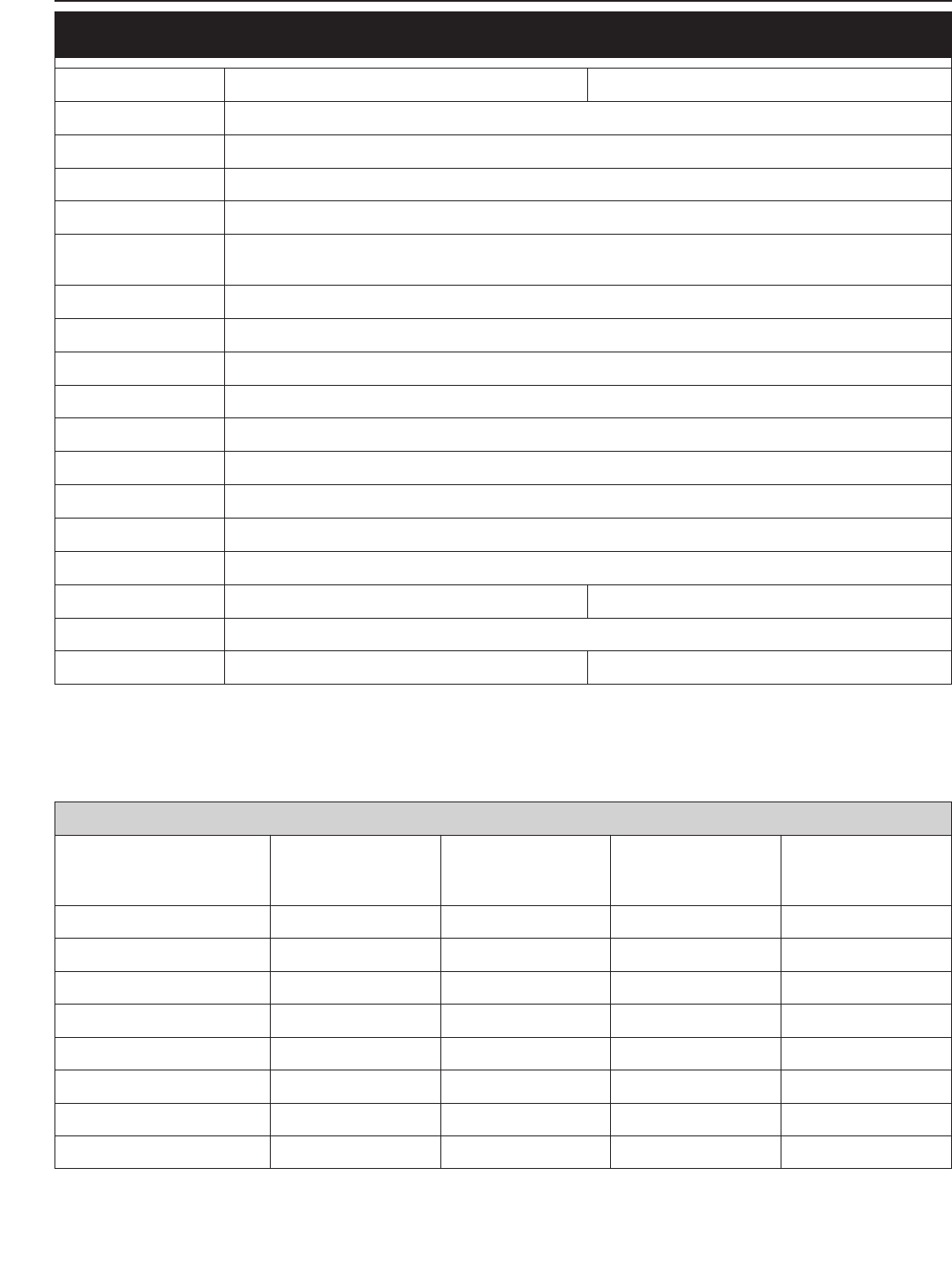
REPLY FAX FOR REPAIR MANUALS
We have made every effort to make our repair manuals as accurate as possible but it is always possible
for a mistake or two to creep in.
To keep improving the quality of our repair manuals, we request mechanics and shop foremen to assist us
as follows:
If you find any errors or inaccuracies in one of our repair manual - whether these are technical errors,
incorrect or unclear repair procedures, tool problems, missing technical data or torques, inaccurate or
incorrect translations or wording, etc. - please enter the error(s) in the table below and fax the completed
form to us at 0043/7742/6000/5349.
NOTE to table:
– Enter the complete item no. for the repair manual in column 1 (e.g.: 3.210.028-E).
You will find the number on the cover page or in the left margin on each right page of the manual.
– Enter the corresponding page number in the repair manual (e.g.: 5-7c) in column 2.
– Enter the current text (inaccurate or incomplete) in column 3 by quoting or describing the
respective
passage of the text. If your text deviates from the text contained in the repair manual, please write your
text in German or English if possible.
– Enter the correct text in column 4.
Your corrections will be reviewed and incorporated in the next issue of our repair manual.
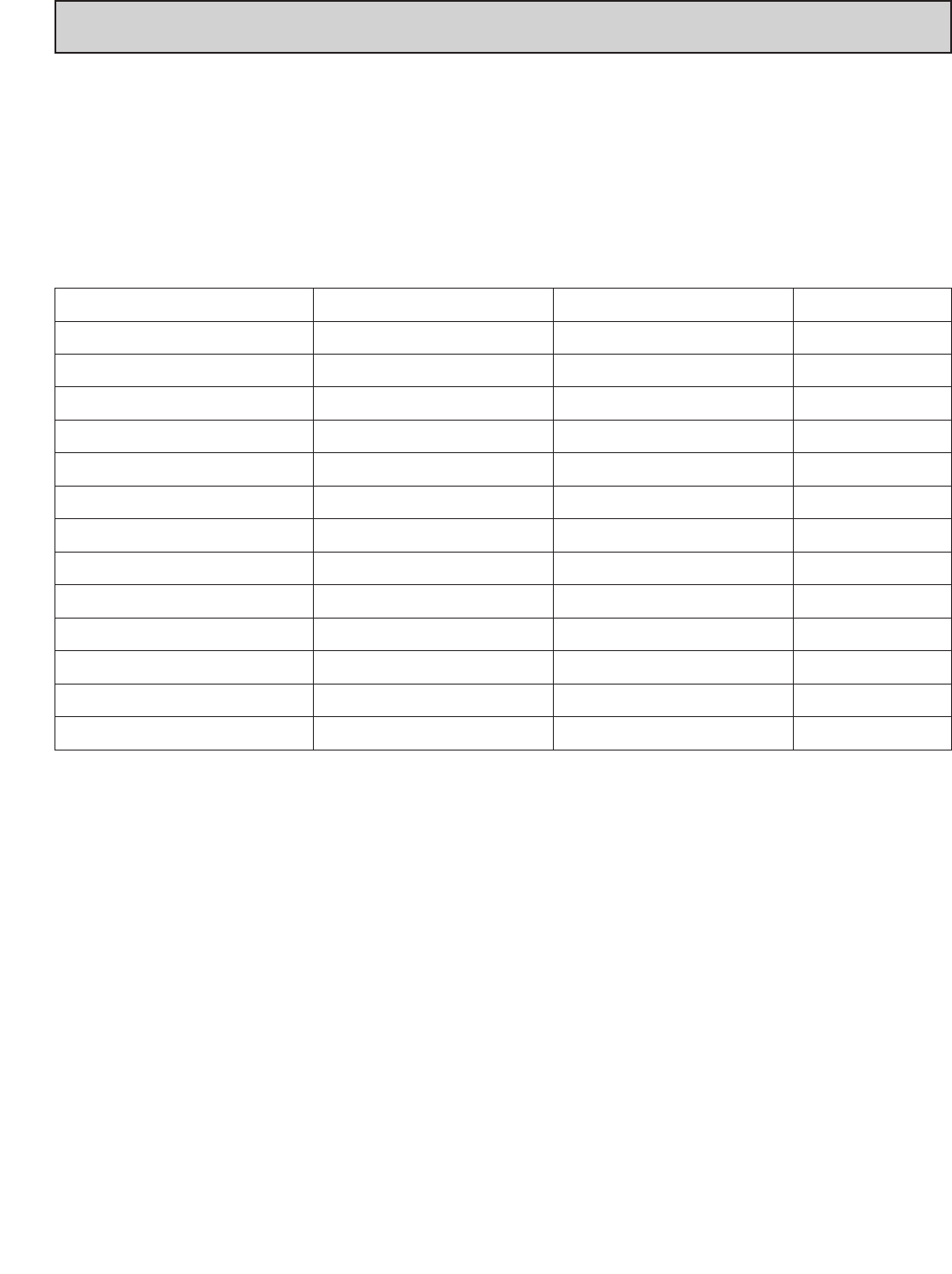
Item no. of repair manual Page Current text Correct text
Additional suggestions, requests or comments on our Repair Manuals (in German or English):
Name mechanic/shop foreman: Company/work shop:

2-1E
Repair manual KTM MINI 50 air/liquid cooled Art.-Nr. 3.206.028-E
GENERAL INFORMATION
OPERATING RANGES OF THE CARBURETOR . . . . . . . . . . . . . . . . . . . . . . . . . . . .2-2
CLEANING AND STORAGE . . . . . . . . . . . . . . . . . . . . . . . . . . . . . . . . . . . . . . . . .2-3
BLEEDING OILPUMP FOR SEPARATE LUBRICATION . . . . . . . . . . . . . . . . . . . . . . .2-4
CHANGING FRONT BRAKE FLUID . . . . . . . . . . . . . . . . . . . . . . . . . . . . . . . . . . . .2-5
CHANGING REAR BRAKE FLUID . . . . . . . . . . . . . . . . . . . . . . . . . . . . . . . . . . . . .2-6
CHECKING BRAKE PADS AND BRAKE DISCS . . . . . . . . . . . . . . . . . . . . . . . . . . . .2-6
2
INDEX
B
C
D
A
12
2-2E
main jet
jet needle
jet needle
idling jet
idling jet
throttle valve
Repair manual KTM MINI 50 air/liquid cooled Art.-Nr. 3.206.028 -E
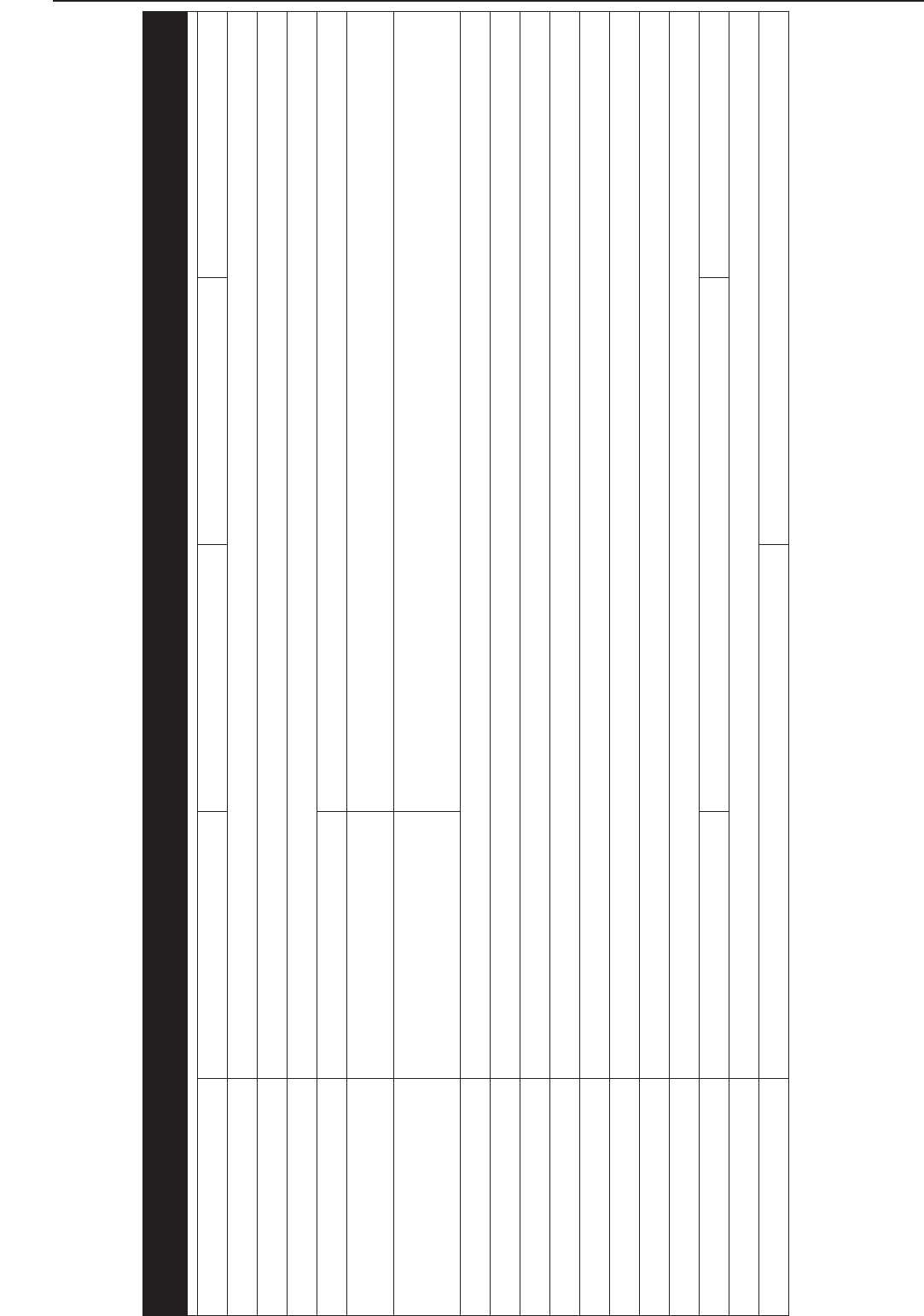
Carburetor adjustment
Basic information about original carburetor setting
The original carburetor setting was adapted for an altitude of approx. 500 meters (1600 ft.) above sea level, and the ambient
temperature of approx. 20° C (68° F), mainly for off-road use and central European premium-grade fuel (ROZ 95).
Mixing ratio 2-stroke motor oil:super fuel up to model 2005 1:40, as of model 2006 1:60.
Basic information about change of the carburetor setting
Always start out from the original carburetor setting. Essential requirements are a clean air filter system, air-tight exhaust system
and an intact carburetor. Experience has shown that adjusting the main jet, the idling jet and the jet needle is sufficient and that
changes of other parts of the carburetor will not greatly affect engine performance.
RULE OF THUMB: high altitude or high temperatures choose leaner carburetor adjustment
low altitude or low temperatures choose richer carburetor adjustment
!
WARNING
!
–ONLY USE PREMIUM-GRADE GASOLINE ROZ 95 MIXED WITH HIGH-GRADE TWO-STROKE ENGINE OIL. OTHER TYPES OF GASOLINE CAN CAUSE
ENGINE FAILURE, AND USE OF SAME WILL VOID YOUR WARRANTY.
–O
NLY USE HIGH-GRADE 2-STROKE ENGINE OIL OF KNOWN BRANDS (I. E. Motorex Cross Power 2T).
–L
ESS OIL OR LOW-GRADE OIL CAN CAUSE EXCESSIVE WEAR OF THE PISTON. USING TOO MUCH OIL, THE ENGINE CAN START SMOKING AND FOUL THE
SPARK PLUG.
–I
N THE CASE OF A LEANER ADJUSTMENT OF THE CARBURETOR PROCEED CAUTIOUSLY. ALWAYS REDUCE THE JET SIZE IN STEPS OF ONE NUMBER TO
AVOID OVERHEATING AND PISTON SEIZURE.
NOTE: If despite a changed adjustment the engine does not run properly, look for mechanical faults and check the ignition
system.
Basic information on carburetor wear
As a result of engine vibrations, throttle valve, jet needle, and needle jet are subjected to increased wear. This wear may cause
carburetor malfunction (e.g., rich mixture). Therefore, these parts should be replaced after 1000 hours of using.
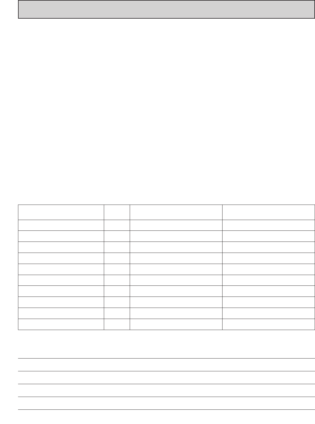
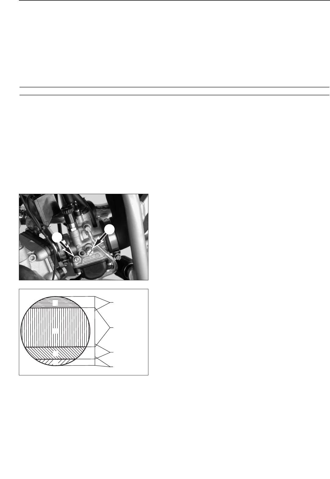
Idling range – A
Operation with closed throttle valve. This range is influenced by the
position of the mixture adjusting screw 1and the idle adjusting screw
2. Only make adjustments when the engine is hot.
To this end, slightly decrease the idling speed of the engine by means
of the idle adjusting screw. Turning it clockwise produces a higher
idling speed and turning the screw counterclockwise produces a lower
idling speed. Create a round and stable engine speed using the mixture
adjusting screw (basic position of the mixture adjusting screw = open
3.5/3 turns). Then adjust to the normal idling speed by means of the
idle adjusting screw.
Opening up – B
Engine behavior when the throttle opens. The idle jet and the shape of
the throttle valve influences this range. If, despite good idling-speed
and part-throttle setting, the engine sputters and smokes when the
throttle is fully opened and develops its full power not smoothly but
suddenly at high engine speeds, the mixture to the carburetor will be
too rich, the fuel level too high or the float needle is leaking.
Part-throttle range – C
Operation with partly open throttle valve. This range is only influenced
by the jet needle (shape and position). The optimum part-throttle
setting is controlled by the idling setting in the lower range and by the
main jet in the upper range. If the engine runs on a four-stroke cycle or
with reduced power when it is accelerated with the throttle partly open,
the jet needle must be lowered by one notch. If then the engine pings,
especially when accelerating under full power at maximum engine revs,
the jet needle should be raised.
If these faults should occur at the lower end of the part throttle range
at a four-stroke running, make the idling range leaner; if the engine
pings, adjust the idling range richer.
Full throttle range – D
Betrieb bei offenem Gasschieber (Vollgas). Dieser Bereich wird durch
Operation with the throttle fully open (flat out). This range is
influenced by the main jet and the jet needle. If the porcelain of the
new spark plug is found to have a very bright or white coating or if the
engine rings, after a short distance of riding flat out, a larger main jet
is required. If the porcelain is dark brown or black with soot the main
jet must be replaced by a smaller one.
2-3E
Clean your motorcycle regularly in order to keep its painted finish looking shiny and new.
The best manner would be to use warm water that has been mixed with a commercially available washing detergent and a
sponge. The hard dirt can be removed before with the help of a soft water jet.
!
CAUTION
!
NEVER CLEAN YOUR MOTORCYCLE WITH A HIGH-PRESSURED CLEANER OR A HIGH-PRESSURED WATER JET. OTHERWISE THE WATER MIGHT RUN INTO THE
ELECTRICAL COMPONENTS, CONNECTORS, SHEATHED CABLES, BEARINGS, CARBURETOR ETC. AND CAUSE MAILFUNCTIONS, I.E., LEAD TO THE
PREMATURE DESTRUCTION OF THESE PARTS.
– You should use commercially available detergents to clean the motorcycle. Heavily soiled parts should also be cleaned with
the help of a paint brush.
– Befor cleaning with water, plug the exhaust pipe to prevent water ingress.
– After the motorcycle has been rinsed with a soft water jet, it should be dried by air pressure and a cloth. Then take a short
drive until the engine has reached its operating temperature, and also operate the brakes. The heat also causes the water at
the inaccessible parts of the engine and the brakes to evaporate.
– Slide back the protective covers on the handlebar-mounted instruments so that any water that may have seeped into this part
of the motorcycle is allowed to evaporate.
– After the motorcycle has cooled down, oil and grease all the gliding bearing parts. Also treat the chain with a chain spray.
– To prevent failures in the electric system, you should treat the short circuit button with a contact spray.
CLEANING
If you want to put your motorcycle away for longer periods of time, please observe the following instructions:
– Clean motorcycle thoroughly (see chapter: CLEANING)
– Change engine oil (old engine oil contains aggresive contaminations).
– Check antifreeze and amount of cooling liquid.
– Let the engine warm up again, close fuel tap and wait until the engine dies off by itself. In this way, the carburetor jets are
prevented from becoming resin-clogged by the old fuel.
– Remove spark plug and fill in approx. 5 ccm of engine oil into the cylinder through the opening. Actuate kick-starter 10 times
in order to distribute the oil onto the cylinder walls and mount the spark plug.
– Let fuel flow out of tank into an appropriate basin.
– Correct tire pressure.
– Lubricate bearing points of the control levers, foot rests, etc. as well as the chain.
– The storage place should be dry and not be subject to overly great temperature fluctuations.
– Cover the motorcycle with an air permeable tarpaulin or blanket. Do not use non-air-permeable materials, as possible
humidity might not be able to escape and thereby cause corrosion.
!
CAUTION
!
IT WOULD BE VERY BAD TO LET THE ENGINE RUN FOR A SHORT TIME DURING THE STORAGE PERIOD. THE ENGINE WOULD NOT GET WARMED UP
ENOUGH AND THE THUS DEVELOPED STEAM WOULD CONDENSE DURING THE COMBUSTION PROCESS AND CAUSE THE EXHAUST TO RUST.
USE AFTER PERIOD OF STORAGE
– Fill up tank with fresh fuel.
– Check motorcycle as before each start (see driving instructions)
– Take a short, careful test ride first.
STORAGE
1
2
2
3A
4
4
2-4E
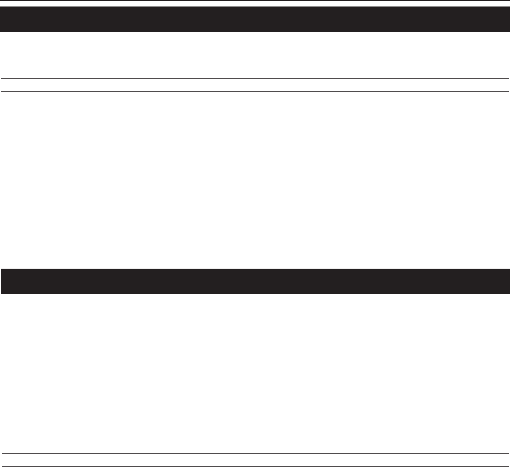
Bleeding oilpump for separate lubrication up to model 2003
Clamp oil lines 1and 2as shown.
Add 2 stroke engine oil (for example Motorex Cross Power 2T) with a
syringe until the bubble-free oil starts to leak out of the line 2.
After bleeding the oil pump, mount both oil lines and fill the oil tank
with 2 stroke engine oil (for example Motorex Cross Power 2T).
!
CAUTION
!
HOSE 2LEADING FROM THE OIL PUMP TO THE CARBURETOR MUST BE INSTALLED
WITHOUT KINKS.
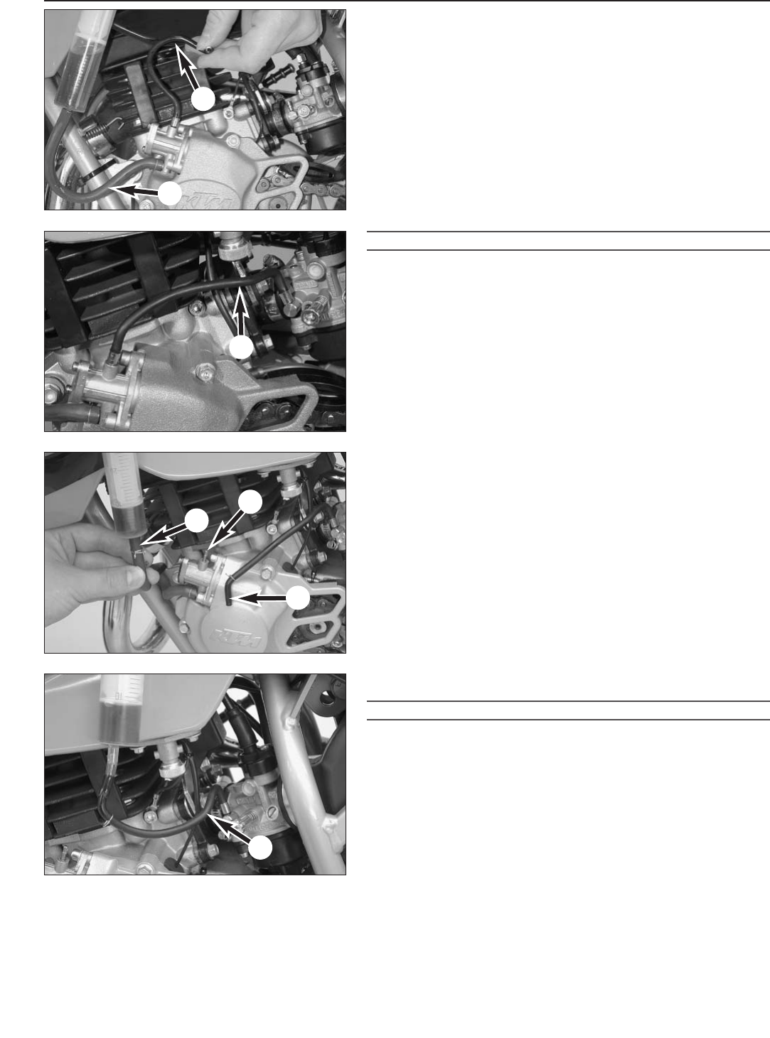
Bleeding the oil pump for the separate lubrication from the 2004
model
Disconnect the oil line 3from the oil tank and oil line 4from the oil
pump. Add two-stroke engine oil for separate lubrication with a syringe
until the bubble-free oil leaks out of hole Aon the oil pump. Connect
the oil line 2to the oil tank. Use the syringe to bleed the oil line 4to
the carburetor and connect to the oil pump.
Afterwards, fill the oil tank with two stroke engine oil (e.g.: Motorex
Cross Power 2T).
!
CAUTION
!
ALWAYS MAKE SURE YOU RUN THE OIL HOSES WITHOUT KINKS.
Repair manual KTM MINI 50 air/liquid cooled Art.-Nr. 3.206.028 -E
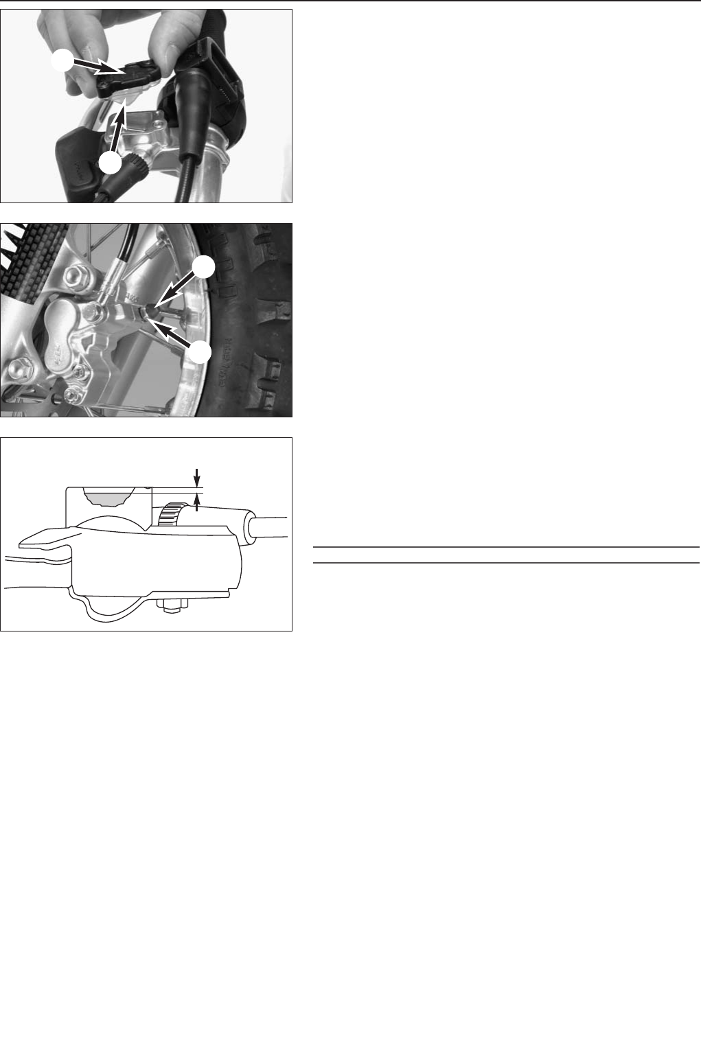
Changing front brake fluid (not Mini Adventure)
– Move the hand brake cylinder into horizontal position.
– Disassemble the cover 1together with the rubber boot 2from the
brake fluid reservoir.
– Press the brake caliper pistons all the way back.
– Use a syringe to extract the used brake fluid and add fresh DOT 5.1
brake fluid (Motorex Brake Fluid DOT 5.1).
– Use a commercial extractor (shop equipment) to extract the used
brake fluid out of the system through the bleeder screw 3on the
brake caliper. Make sure the brake fluid reservoir is always filled
with enough fresh brake fluid.
– Tighten the bleeder screw 3and attach the dust cap 4again.
– Add DOT 5.1 brake fluid (Motorex Brake Fluid DOT 5.1) up to
5 mm under the top edge of the reservoir. Remount the rubber boot,
cover and screws.
– Wash off any overflowing or spilled brake fluid with water.
– Actuate the hand brake lever until you feel the point of pressure.
!
CAUTION
!
–N
EVER USE DOT 5 BRAKE FLUID. IT IS BASED ON SILICONE OIL AND DYED
PURPLE. GASKETS AND BRAKE HOSES WILL BE DAMAGED IF DOT 5 BRAKE
FLUID IS USED.
–B
RAKE FLUID CAN CAUSE SKIN IRRITATIONS. AVOID COMING INTO CONTACT WITH
THE SKIN OR EYES. IF BRAKE FLUID SPLASHES INTO YOUR EYES, RINSE
THOROUGHLY WITH WATER AND CONSULT A DOCTOR.
–M
AKE SURE NO BRAKE FLUID COMES INTO CONTACT WITH PAINTED PARTS SINCE
BRAKE FLUID WILL CORRODE THE PAINTWORK!
–O
NLY USE CLEAN, NEW BRAKE FLUID FROM TIGHTLY SEALED CONTAINERS.
2-5E
5 mm
1
2
3
4
Repair manual KTM MINI 50 air/liquid cooled Art.-Nr. 3.206.028 -E
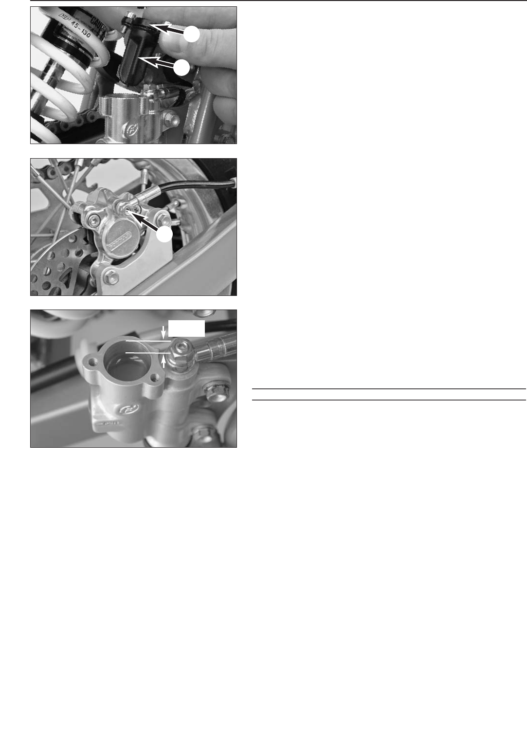
Changing rear brake fluid
(50 SX, 50 Supermoto)
– Move the vehicle in a vertical position.
– Disassemble the cover 1together with the rubber boot 2from the
brake fluid reservoir.
– Press the brake caliper pistons all the way back.
– Use a syringe to extract the used brake fluid and add fresh DOT 5.1
brake fluid (Motorex Brake Fluid DOT 5.1).
– Completely remove the bleeder screw 3.
– Extract the old brake fluid from the system using the bleeder syringe
503.29.050.000. Always make sure that the brake fluid reservoir is
filled with sufficient fresh brake fluid.
– Mount the bleeder screw 3.
– Add DOT 5.1 brake fluid (Motorex Brake Fluid DOT 5.1) up to
15 mm under the top edge of the reservoir. Remount the rubber
boot, cover and screws.
– Wash off any overflowing or spilled brake fluid with water.
– Actuate the foot brake lever until you feel the point of pressure.
!
CAUTION
!
–N
EVER USE DOT 5 BRAKE FLUID. IT IS BASED ON SILICONE OIL AND DYED
PURPLE. GASKETS AND BRAKE HOSES WILL BE DAMAGED IF DOT 5 BRAKE
FLUID IS USED.
–B
RAKE FLUID CAN CAUSE SKIN IRRITATIONS. AVOID COMING INTO CONTACT WITH
THE SKIN OR EYES. IF BRAKE FLUID SPLASHES INTO YOUR EYES, RINSE
THOROUGHLY WITH WATER AND CONSULT A DOCTOR.
–M
AKE SURE NO BRAKE FLUID COMES INTO CONTACT WITH PAINTED PARTS SINCE
BRAKE FLUID WILL CORRODE THE PAINTWORK!
–O
NLY USE CLEAN, NEW BRAKE FLUID FROM TIGHTLY SEALED CONTAINERS.
Checking brake pads and brake disks
– See Owner's Manual
2-6E
1
2
3
15 mm
3-1E
REMOVING AND REFITTING ENGINE
Repair manual KTM MINI 50 air/liquid cooled Art.-Nr. 3.206.028-E
REMOVING THE ENGINE . . . . . . . . . . . . . . . . . . . . . . . . . . . . . . . . . . . . . . . . . .3-2
INSTALLING THE ENGINE . . . . . . . . . . . . . . . . . . . . . . . . . . . . . . . . . . . . . . . . .3-4
INDEX
3
1
2
3
4
5
6
3-2E
Repair manual KTM MINI 50 air/liquid cooled Art.-Nr. 3.206.028-E
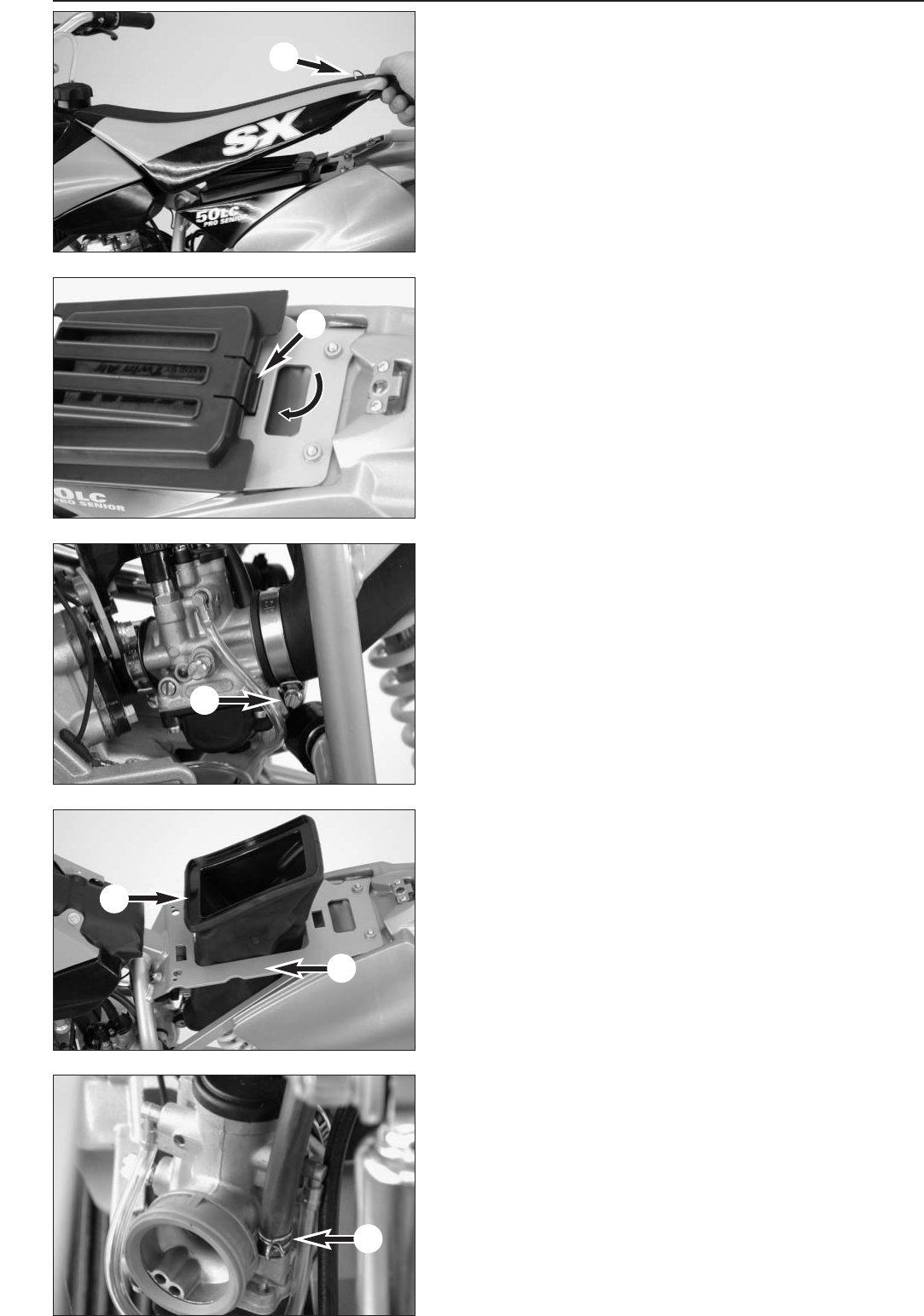
Removing the engine
NOTE: the following steps are shown on a model with LC-engine, on a
model with AC-engine a few works are not necessary like draining
coolant liquid, removing and mounting the radiator and the radiator
shield, bleeding the cooling system.
Clean the entire vehicle thoroughly before removing the engine.
To avoid burns, allow the motorcycle to cool before starting to work.
– Jack up the motorcycle on a sturdy work stand.
– Turn quick release 1on the seat 180°, lift back of seat slightly and
pull back.
– Remove the cover of the air filter by reaching through the recess in
the panel and pushing the locating tab 2 forwards with your finger.
– Remove air filter element.
– Loosen hose clamp 3on the air filter box of the carburetor and
remove air filter box.
– Pull air filter box 4up through the retaining bracket 5by
deforming it.
– Close fuel cock and disconnect fuel hose 6from the carburetor.
1
2
3
4
5
3-3E
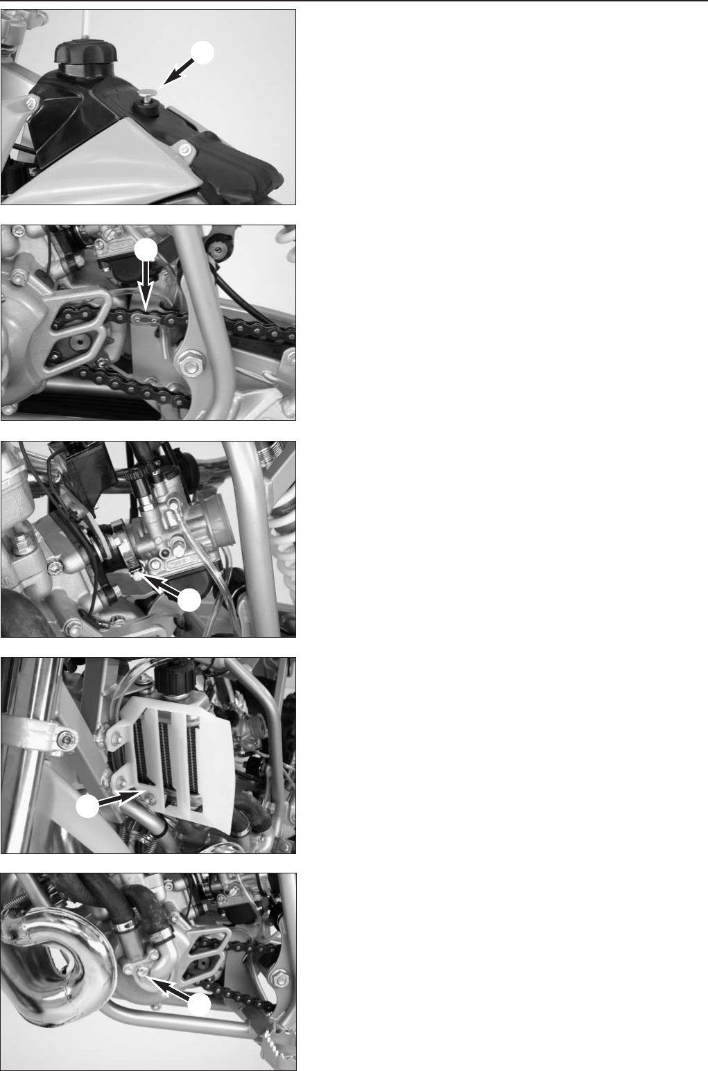
– Loosen retaining bolt on tank 1and remove from tank together with
the rubber grommet.
– Lift tank from the frame.
– Open chain joint 2and remove chain.
– Loosen hose clamp 3of the intake flange on the carburetor, pull
carburetor back and swing to the side.
NOTE: if the carburetor is not being serviced, it does not need to be
removed - the carburetor openings should however be covered with a
clean cloth and the gasoline drained from the float chamber.
– Remove radiator shield on the right and left 4.
– Unbolt radiator cap, open drain plug 5and allow cooling fluid to
drain into a receptacle. Then remount the drain plug with a new
sealing ring and tighten (5 Nm/4 ft.lb).
1
1
2
3
4
4
5
6
78
3-4E
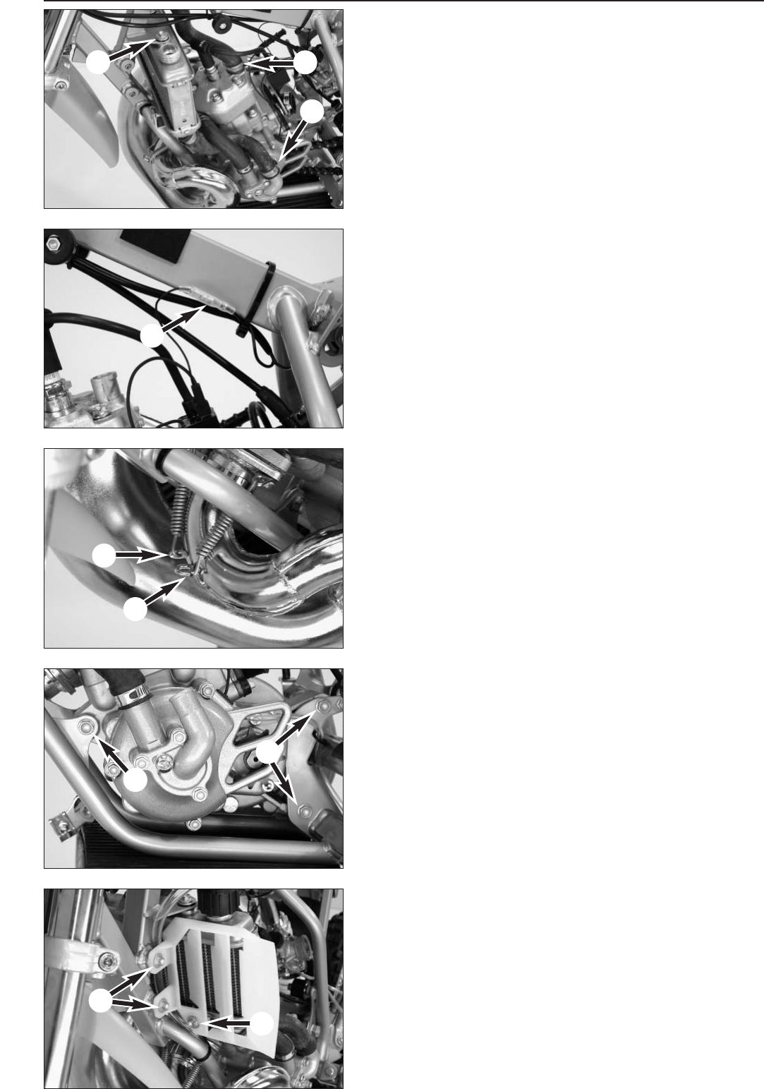
– Loosen hose clamp 1and pull both hoses from their connections.
– Unbolt radiator retaining bolt 2and laterally remove radiator with
water hoses from the frame.
– Carefully pull socket connector 3apart.
– Detach both exhaust springs 4with a suitable wrench, remove
springs.
– Unbolt the exhaust bracket on the right and pull exhaust off towards
the front.
– Loosen engine mounting bolts 5and 6, lift engine from the frame.
Installing the engine
– Lift engine into the frame and fasten with bolt 5(M8x65 with nut)
and 2 bolts 6(M8x55).
– Tighten bolts to 30 Nm (22 ft.lb).
– Mount exhaust, insert springs 4and tighten bolt for exhaust bracket
M6x15 on the right.
– Carefully connect socket connector 3.
– Position radiator in the frame and tighten the radiator retaining bolts
2(M6x10 with washer 18/6,5/1,5) to 10 Nm (7 ft.lb). Connect
hoses and tighten hose clamps 1.
– Fill cooling liquid (total filling amount approx. 0,5 liter).
– Mount radiator shield on the right and left.
NOTE: bolts 7(M6x10) are bolted onto the side of the frame, bolt 8
(M6x15) is bolted into the radiator bracket.
Repair manual KTM MINI 50 air/liquid cooled Art.-Nr. 3.206.028 -E
1
2
3
4
3-5E
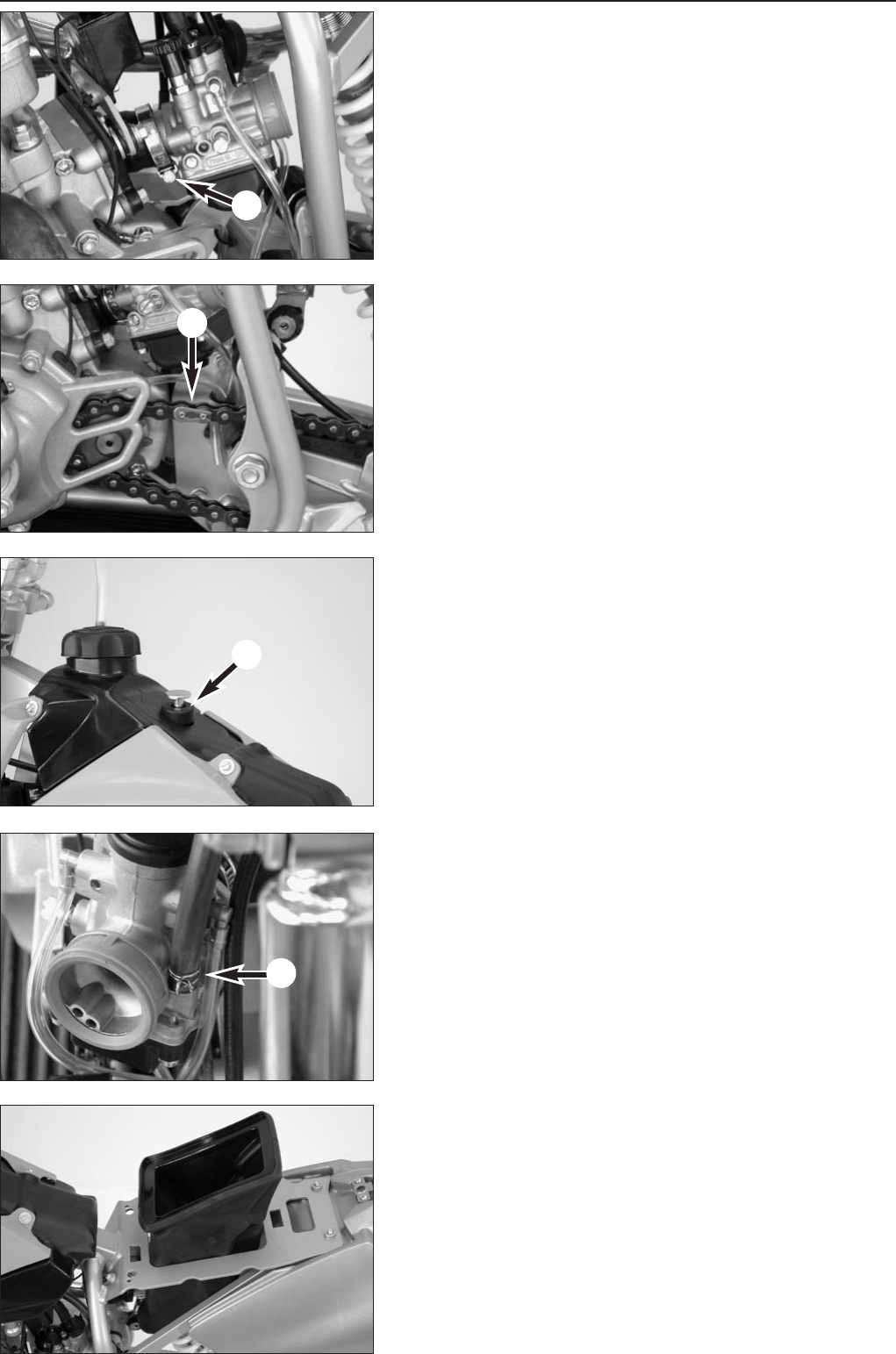
– Install carburetor on the intake flange and tighten hose clamp 1.
– Place chain on rear sprocket and pinion, mount chain joint 2and
secure.
NOTE: make sure the locking member runs in the right direction (see
photo). The closed side of the safety device must point in the running
direction.
– Mount tank and bolt tight. Do not forget the rubber grommet 3for
the bolt.
– Connect fuel hose 4to the carburetor and secure.
– Slide air filter box into the frame bracket.
1
23
3-6E
Repair manual KTM MINI 50 air/liquid cooled Art.-Nr. 3.206.028 -E
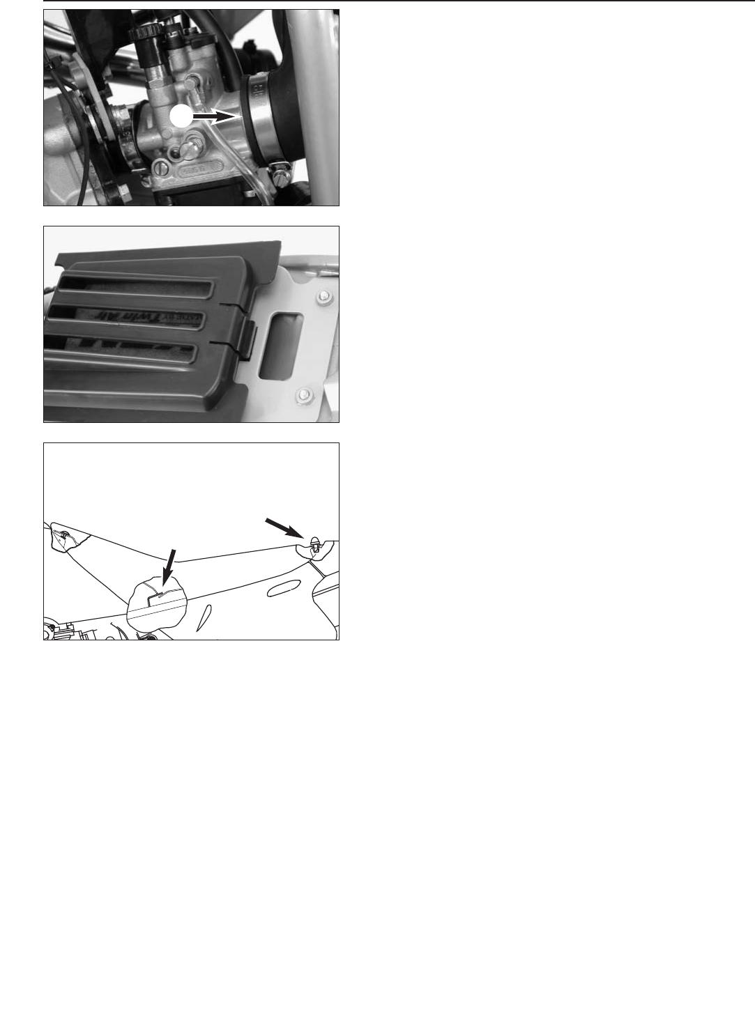
– Attach connection 1of the air filter box to the carburetor and
tighten hose clamp.
– Insert air filter element in the air filter box and mount cover.
NOTE: the locating tabs in the cover must engage in the panel.
– Mount seat. Make sure the retaining bracket 2is inserted properly.
Insert quick release 3in the dolly and turn 180°.
After installing the engine, perform a short test run and correct the
cooling fluid level (LC-engine). Then take the motorcycle on a road test.
After the road test, check the engine, the fuel system and the exhaust
system for tightness.

4-1E
DISASSEMBLING THE ENGINE
Repair manual KTM MINI 50 air/liquid cooled Art.-Nr. 3.206.028-E
SPECIAL TOOLS - ENGINE . . . . . . . . . . . . . . . . . . . . . . . . . . . . . . . . . . . . . . . . .4-2
FIXING THE ENGINE . . . . . . . . . . . . . . . . . . . . . . . . . . . . . . . . . . . . . . . . . . . . .4-3
DRAINING GEAR OIL . . . . . . . . . . . . . . . . . . . . . . . . . . . . . . . . . . . . . . . . . . . . .4-3
DISMOUNTING INTAKE FLANGE AND IGNITION COIL . . . . . . . . . . . . . . . . . . . . . .4-3
DISMOUNTING IGNITION COVER . . . . . . . . . . . . . . . . . . . . . . . . . . . . . . . . . . . .4-3
DISMOUNTING IGNITION STATOR . . . . . . . . . . . . . . . . . . . . . . . . . . . . . . . . . . .4-4
DISMOUNTING CYLINDER, CYLINDERHEAD AND PISTON . . . . . . . . . . . . . . . . . . .4-4
DISMOUNTING IGNITION ROTOR . . . . . . . . . . . . . . . . . . . . . . . . . . . . . . . . . . . .4-5
SPLIT THE CASING HALVES . . . . . . . . . . . . . . . . . . . . . . . . . . . . . . . . . . . . . . .4-5
DISMOUNTING CLUTCH AND PRIMARY DRIVE . . . . . . . . . . . . . . . . . . . . . . . . . .4-6
INDEX
4
15
50
8
130
75
2
1
4
3
5
6
4-2E
Repair manual KTM MINI 50 air/liquid cooled Art.-Nr. 3.206.028 -E
SPECIAL TOOLS ENGINE 50 AC/LC
FIG PARTNUMBER DESCRIPTION
1590.29.021.000 Puller for flywheel
2451.12.021.000 Rotor holding tool
3451.29.006.000 Adjusting plate for Dimension „X“
46 899 785 Loctite 243 blue
5451.29.075.000 Tachometer
6503.29.050.000 Bleeding syringe
1
2
3
4
5
5
5
6
7
4-3E
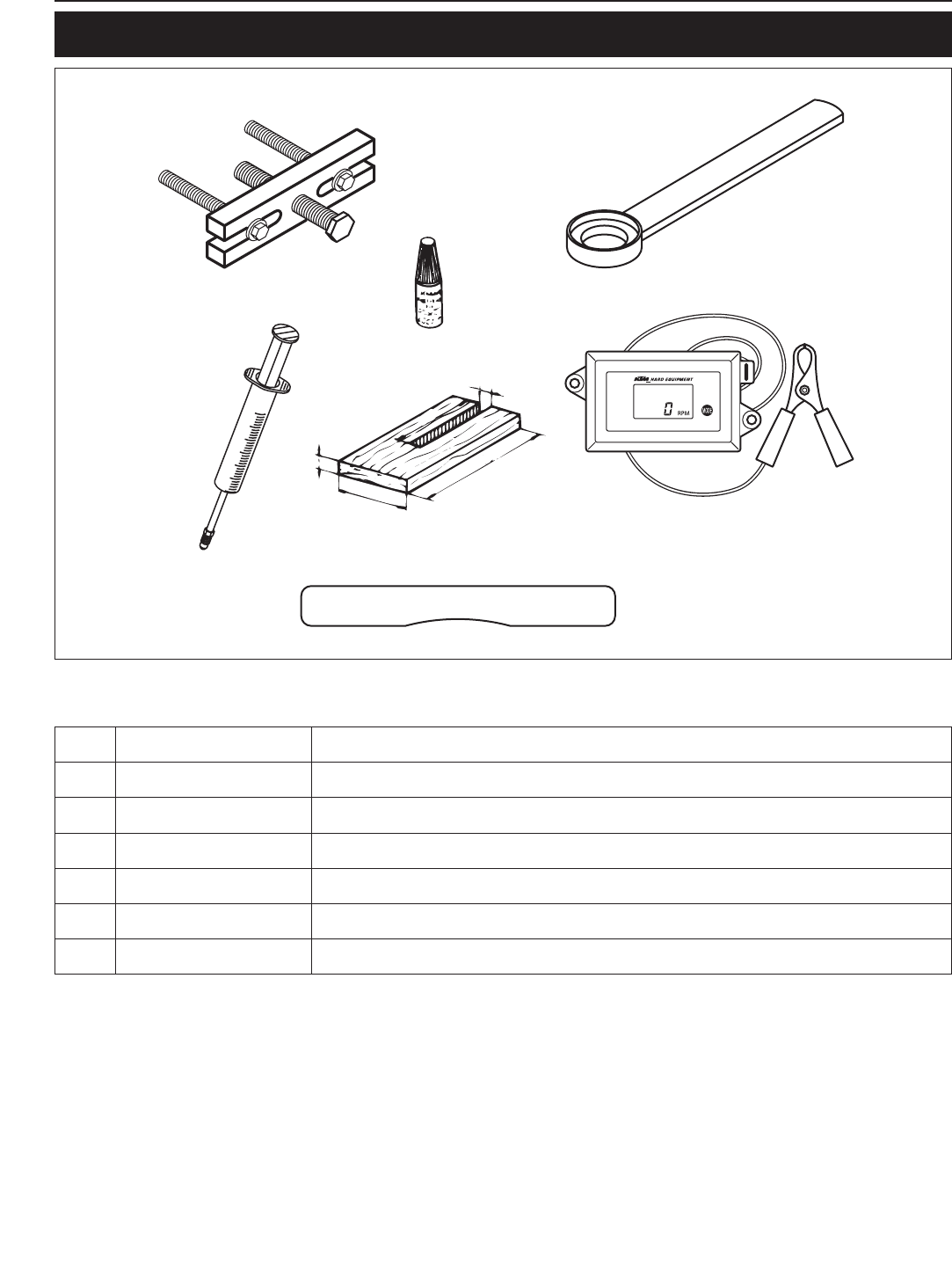
Clamp the engine using a vice
– Clean the engine thoroughly prior to disassembling.
– The engine can be clamped with a vice, using a protective pad to
clamp the lower rear bracket (see photo).
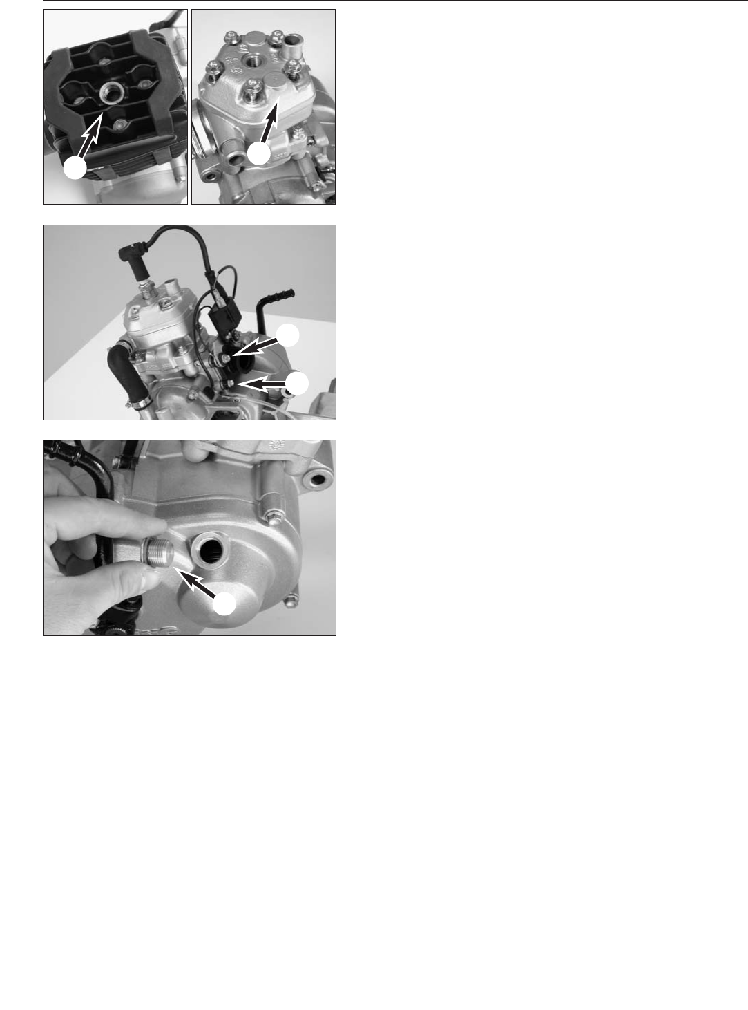
Drain the transmission oil
– Remove the transmission oil drain plug 1including the sealing ring
and allow transmission oil to drain.
– Mount the transmission oil drain plug with new sealing ring and
tighten to 15 Nm (11 ft.lb).
.
Remove water hose, intake flange and ignition coil
– Loosen hose clamps and remove water hose 2(only LC-engine).
– Pull plug 3from the ignition coil, disconnect spark plug cap from
the spark plug.
– Loosen 4 bolts on the intake flange 4. Remove the ignition coil with
bracket, intake flange and reed valve housing.
– Remove spark plug.
.
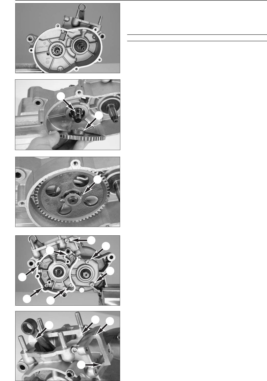
Remove ignition cover and pump.
– Loosen bolt 5and remove ignition cover.
NOTE:
– The water pump 6is located on the ignition cover of the LC-engine.
– The ignition cover is centered with 2 dowels. They usually stay in the
engine case and should be removed with a suitable wrench.
NOTE: water pump shafts from the 2004 model have a hole containing
a spring 7.
1
2
2
3
4
4
5
6
7
8
4-4E
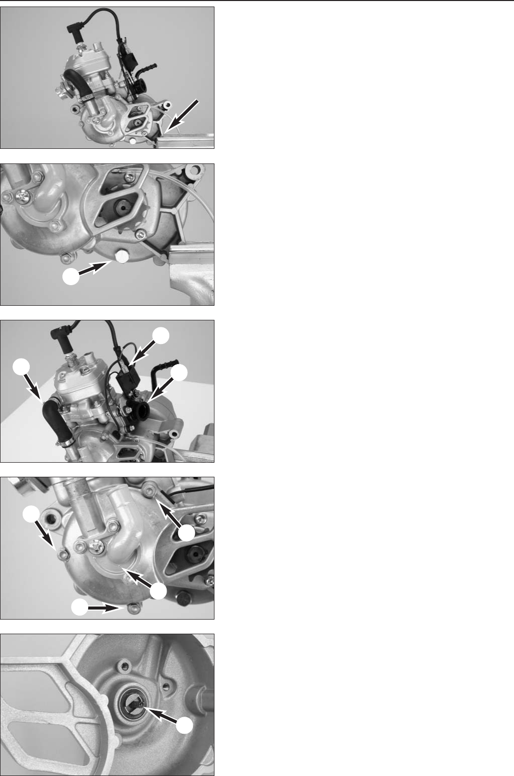
Remove ignition stator.
– Pull cable guide 1from the case.
– Remove allan bolts 2of the ignition stator 3.
– Carefully pull stator 3out of the case.
Remove cylinder head, cylinder and pistons.
– Loosen bolts on cylinder head crosswise and remove.
– Discard washers (LC-engine), remove cylinder head 4.
– Remove gasket 5(AC-engine) or O-rings 6(LC-engine) from
cylinder and discard.
– Loosen 4 bolts 7on the cylinder base crosswise and remove;
carefully lift the cylinder off.
– Place pistons on a self-made mounting board.
– Remove ring lock 8from the piston pin using a suitable tool.
– Push piston pins out of the piston by hand, remove pistons and pull
needle bearing from the conrod.
– Remove cylinder base gasket.
Repair manual KTM MINI 50 air/liquid cooled Art.-Nr. 3.206.028 -E
1
2
3
4
5
55
5
6
7
7
4-5E
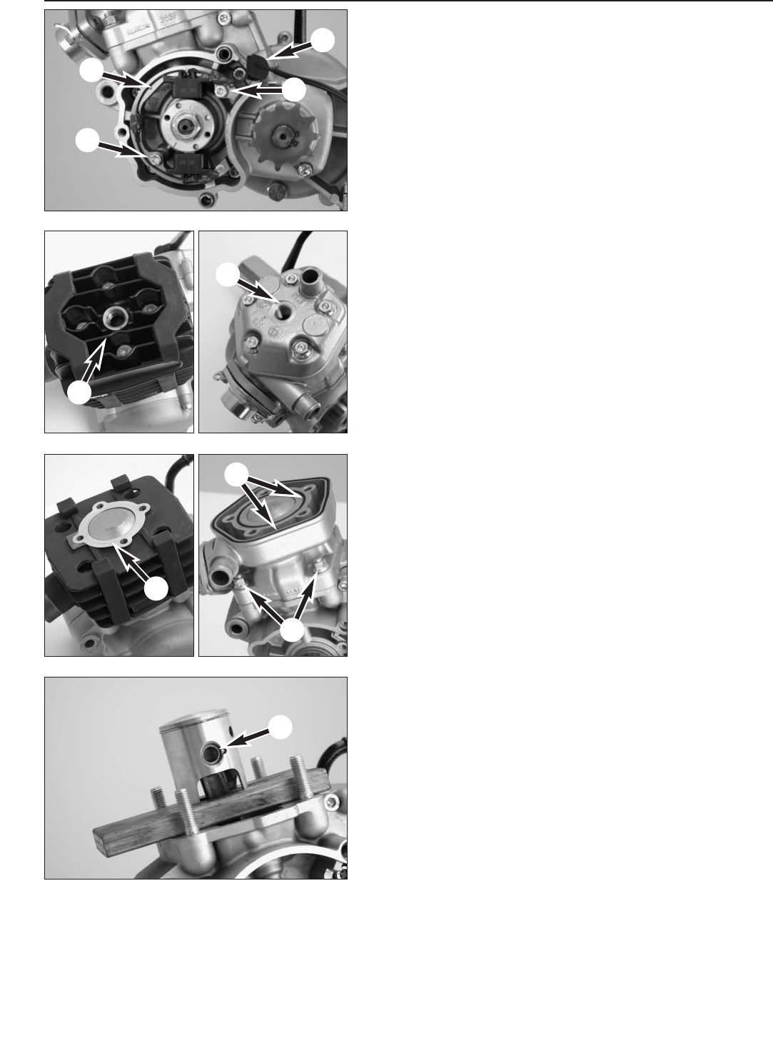
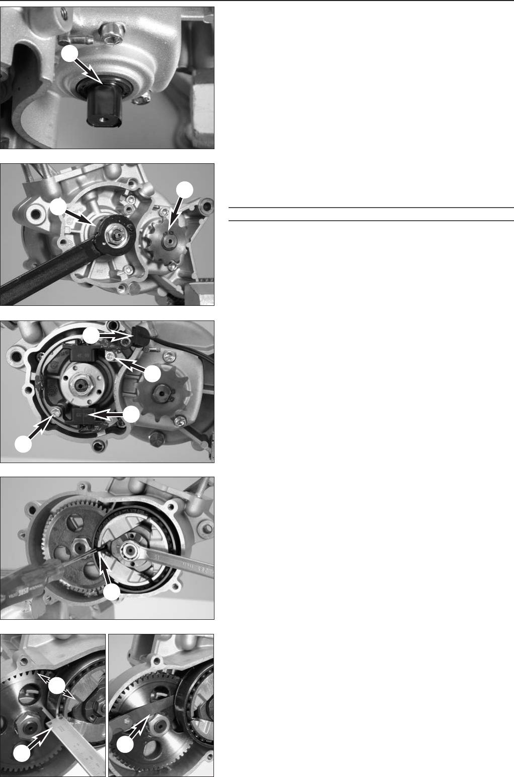
Pull off ignition rotor
– Hold ignition rotor 1with special tool 2, open the nut and remove.
NOTE: a washer is located under the nut; the magnetic attraction of the
rotor causes it to adhere to the rotor.
!
CAUTION
!
MAKE SURE THE TWO PINS OF THE SPECIAL TOOL DO NOT CATCH THE THREADED
HOLES, OTHERWISE THE THREADING WILL BE DAMAGED AND THE ROTOR CAN NO
LONGER BE REMOVED.
– Remove circlip 3from the chain sprocket and remove chain
sprocket.
– Bolt extractor to the rotor with 2 M4x35 bolts, hold extractor in place
and pull rotor 4off by bolting in the extractor bolt.
– Remove woodruff key from the groove.
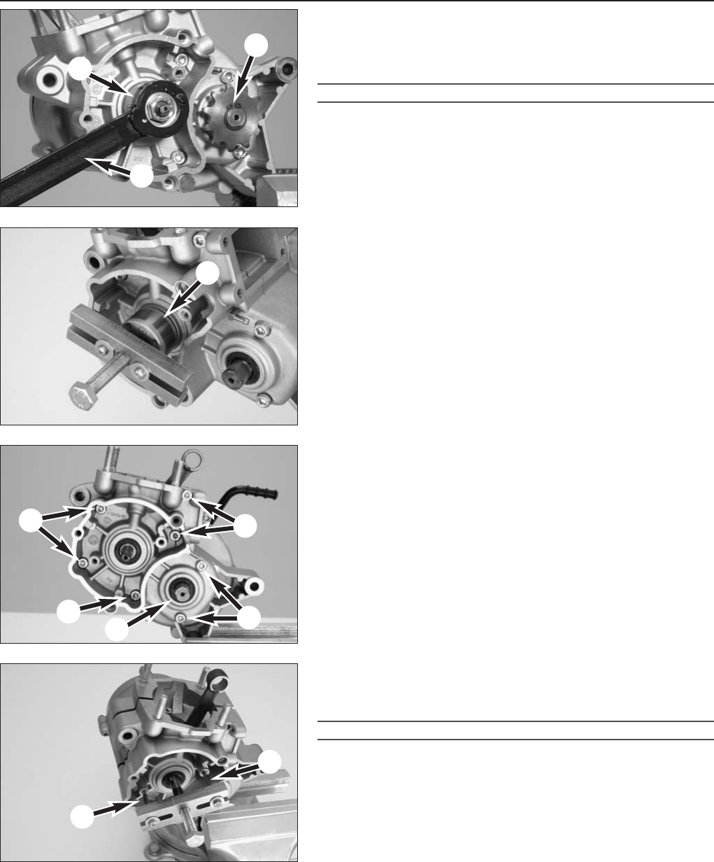
Split the casing halves
– Loosen all 7 allan bolts 5holding the two casing halves together
and set aside.
– Bolt extractor to the casing with 2 M5x50 bolts 7.
– Hold extractor in place and separate the casing by bolting in the
extractor bolt, gently tapping the casing with a plastic hammer to
prevent the bearing on the drive shaft 6from canting.
!
CAUTION
!
IF THE BEARING ON THE DRIVE SHAFT CANTS, STOP PULLING OFF THE CASING. USE
THE PLASTIC HAMMER TO CAREFULLY CORRECT THE DISTORTION, OTHERWISE THE
CASING WILL BE DAMAGED.
– Remove casing; remove seal and discard.
NOTE: the housing halves are centered with 2 dowels which should also
be removed.
11
1
1
2
3
4
5
6
7
8
9
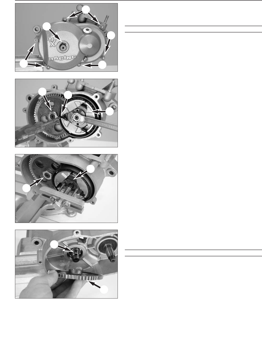
4-6E
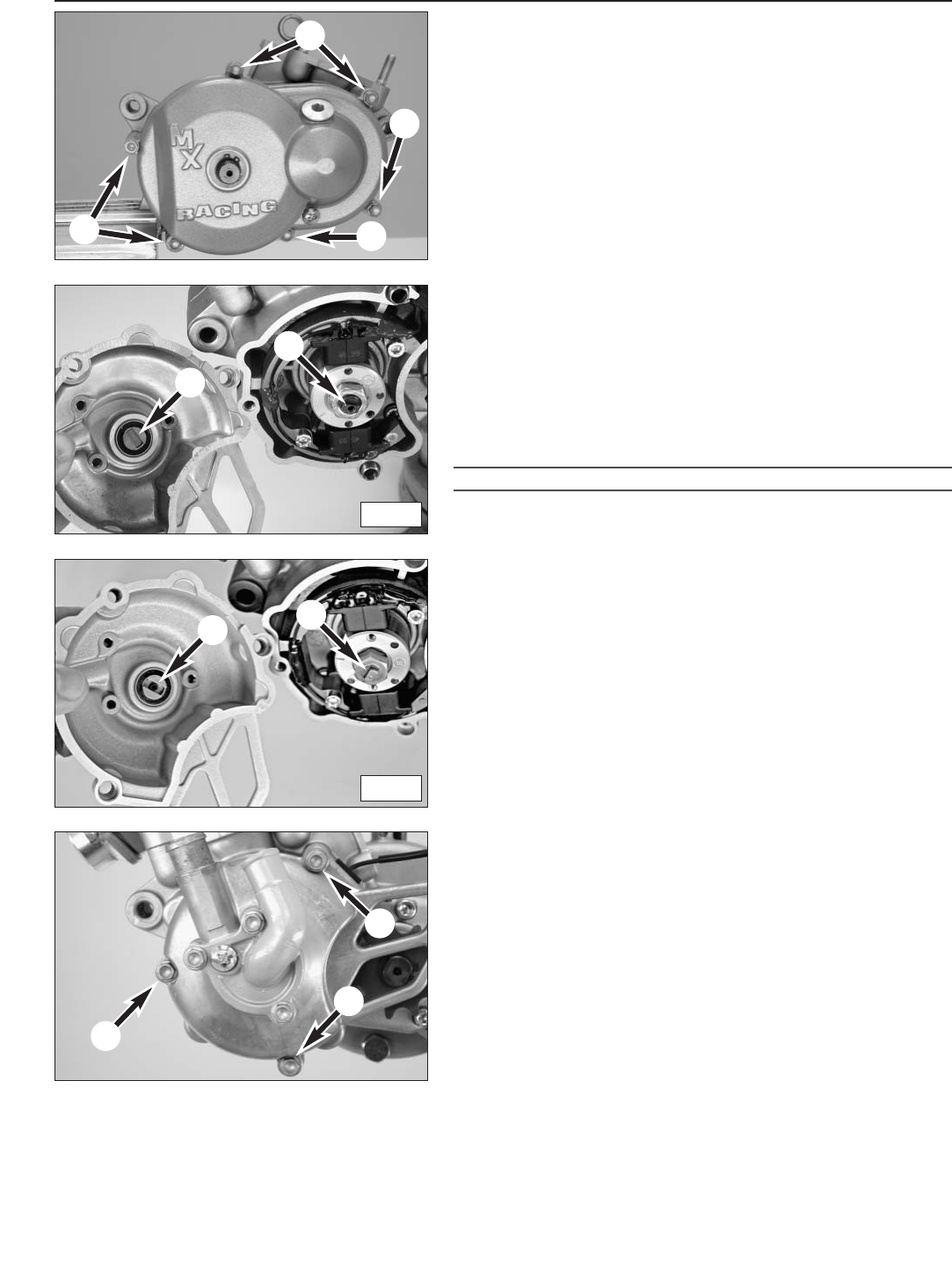
Disassemble the clutch and primary drive
– Rechuck the engine to provide access to the clutch side.
– Remove kickstarter and bolts 1on the clutch cover.
– Remove clutch cover, discarding the seal.
WARNING
DO NOT REMOVE THE CIRCLIP 2, OTHERWISE THE KICKSTARTER SPINDLE MAY FALL
FROM THE CASING AND THE KICKSTARTER SPRING CAUSE INJURIES.
– Block the centrifugal clutch 3with a suitable mandrel 4.
NOTE: the drum and the gear wheel of the primary drive have holes.
Push the mandrel through both holes.
– Bend up the lock washer 5 on the output shaft nut.
– Loosen the nut on the clutch and the output shaft and pull the
mandrel out.
– Remove nut and washer from the crankshaft.
– Bolt the extractor to the hub of centrifugal clutch 6using bolts
M5x50, hold the extractor in place and pull the centrifugal clutch
from the crankshaft by bolting in the extractor bolt.
– Remove the centrifugal clutch from the crankshaft together with the
bearing and spacing washers.
– Remove nut 7and lock washer from the output shaft.
– Remove gear 8on the primary drive from the shaft, remove woodruff
key 9from the shaft groove.
– Press the crankshaft and output shaft out of the casing using a press
or suitable extractor.
!
CAUTION
!
THE TWO SHAFTS MAY NOT BE STRUCK OUT OF THE CASING WITH A HAMMER SINCE
THE CRANKSHAFT OR THE CASING MAY BE DAMAGED.
Repair manual KTM MINI 50 air/liquid cooled Art.-Nr. 3.206.028 -E

5-1E
SERVICING INDIVIDUAL COMPONENTS
Repair manual KTM MINI 50 air/liquid cooled Art.-Nr. 3.206.028-E
RIGHT HOUSING HALF . . . . . . . . . . . . . . . . . . . . . . . . . . . . . . . . . . . . . . . . . . .5-2
LEFT HOUSING HALF . . . . . . . . . . . . . . . . . . . . . . . . . . . . . . . . . . . . . . . . . . . .5-3
CRANKSHAFT . . . . . . . . . . . . . . . . . . . . . . . . . . . . . . . . . . . . . . . . . . . . . . . . .5-3
CLUTCH COVER . . . . . . . . . . . . . . . . . . . . . . . . . . . . . . . . . . . . . . . . . . . . . . . .5-4
WATER PUMP . . . . . . . . . . . . . . . . . . . . . . . . . . . . . . . . . . . . . . . . . . . . . . . . .5-5
REED VALVE HOUSING, INTAKE FLANGE . . . . . . . . . . . . . . . . . . . . . . . . . . . . . .5-5
PISTON . . . . . . . . . . . . . . . . . . . . . . . . . . . . . . . . . . . . . . . . . . . . . . . . . . . . . .5-6
PISTON RING END GAP . . . . . . . . . . . . . . . . . . . . . . . . . . . . . . . . . . . . . . . . . .5-6
CHECKING CYLINDER FOR WEAR . . . . . . . . . . . . . . . . . . . . . . . . . . . . . . . . . . .5-6
CLUTCH . . . . . . . . . . . . . . . . . . . . . . . . . . . . . . . . . . . . . . . . . . . . . . . . . . . . .5-7
SPRINGS OF CLUTCH . . . . . . . . . . . . . . . . . . . . . . . . . . . . . . . . . . . . . . . . . . . .5-7
CHECKING CLUTCH FOR WEAR . . . . . . . . . . . . . . . . . . . . . . . . . . . . . . . . . . . . .5-7
INDEX
5
Engine housing
Note: Read through the following section before commencing work. Then determine the assembly sequence so that the engine
housing halves only need to be heated up once before replacing the bearings.
Having first removed the dowels, in order to expel the bearings or remove them with light mallet blows, the housing halves must
be placed on a suitably large plane surface, supporting the whole of the sealing surface without damaging it. A wooden panel is
best used as a base.
Bearings or shaft seal rings should not be hammered into their seats. If no suitable press is available, use a suitable mandrel and
hammer them in with great care. Cold bearings will practically drop into their seats at an engine housing temperature of approx.
150° C.
After cooling, should the bearings fail to lock in the bore, they are bound to rotate after warming. In that event the housing must
be replaced.
1
23
S
5-2E
Repair manual KTM MINI 50 air/liquid cooled Art.-Nr. 3.206.028 -E
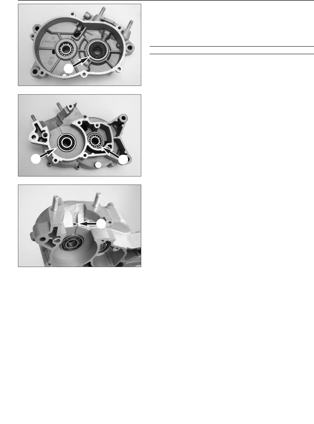
Working on the right half of the engine case
Remove shaft sealing ring 1and heat the engine case half on a heating
plate to approx. 150° C.
NOTE: if the engine case is heated to 150° C and struck on a wooden
surface, the bearings usually fall out of the bearing seats automatically.
If necessary, the bearings must be pushed out.
!
CAUTION
!
–ALWAYS REMOVE DOWELS FIRST TO PREVENT THE CASE FROM BEING DAMAGED.
–T
HE DEVICES (MANDRELS) TO PRESS THE NEW BEARINGS IN PLACE SHOULD BE
DESIGNED SUCH THAT THEY ONLY REST ON THE OUTER RING OF THE BEARING,
OTHERWISE THE BEARINGS WILL BE DAMAGED WHEN FITTED.
Grooved ball bearing for crankshaft 2
Use a suitable mandrel to press the grooved ball bearing into place.
Press the new grooved ball bearing all the way in.
NOTE: the grooved ball bearing of the crankshaft will protrude approx.
1 mm from the surface of the case.
Grooved ball bearing for output shaft 3
Use a suitable mandrel to press the grooved ball bearing into place.
Press the new grooved ball bearing all the way in.
NOTE: the grooved ball bearing of the output shaft should fit flush with
the surface of the case.
Shaft sealing ring for crankshaft 1
Press a new shaft sealing ring into place with the sealing lip to the
inner side.
NOTE: the seal shaft ring will fit approx. 1 mm lower than the surface
of the case.
After the engine case halves have cooled, check all bearings for firm
retention in the bearing seats.
Finally, check the greasing hole Sfor the grooved ball bearing of the
crankshaft and the connection for the gearbox ventilation for clearance.
1
2
4
3
5-3E
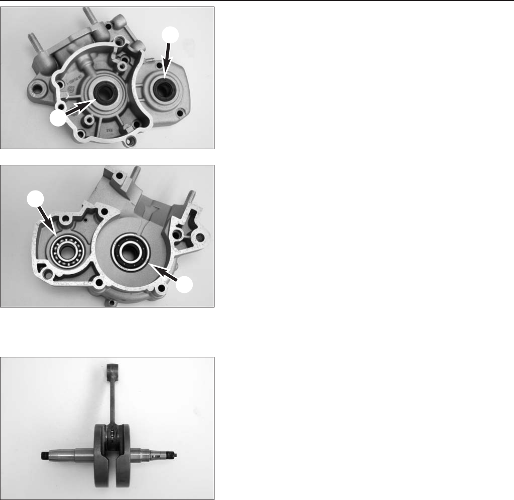
Working on the left half of the engine case
Remove shaft sealing rings 1/2and heat engine case halves on a
heating plate to approx. 150° C.
NOTE:
– If the engine case is heated to 150° C and struck on a wooden
surface, the bearings usually fall out of the bearing seats
automatically. If necessary, the bearings must be pushed out.
– The devices (mandrels) to press the new bearings in place should be
designed such that they only rest on the outer ring of the bearing,
otherwise the bearings will be damaged when fitted.
Grooved ball bearing for crankshaft 3
Use a suitable mandrel to press the grooved ball bearing into place.
Press the new grooved ball bearing all the way in.
NOTE: the grooved ball bearing of the crankshaft will protrude approx.
1 mm from the surface of the case.
Grooved ball bearing for output shaft 4
Use a suitable mandrel to press the grooved ball bearing into place.
Press the new grooved ball bearing all the way in.
NOTE: the grooved ball bearing of the output shaft should fit flush with
the surface of the case.
Shaft sealing ring for crankshaft 1
Press a new shaft sealing ring into place with the sealing lip to the
inner side.
After the engine case halves have cooled, check bearings for firm
retention.
Measure the crankshaft
If continuing to use the crankshaft, check crankshaft journal for lateral
runout.
The lateral runout of the crankshaft journal should be no more than
0.05 mm
NOTE: Conrod bearing and crankshaft can only be checked in
dismantled condition, this should be done in a special workshop.
1
2
67
8
9
3
4
5
5-4E
Repair manual KTM MINI 50 air/liquid cooled Art.-Nr. 3.206.028 -E
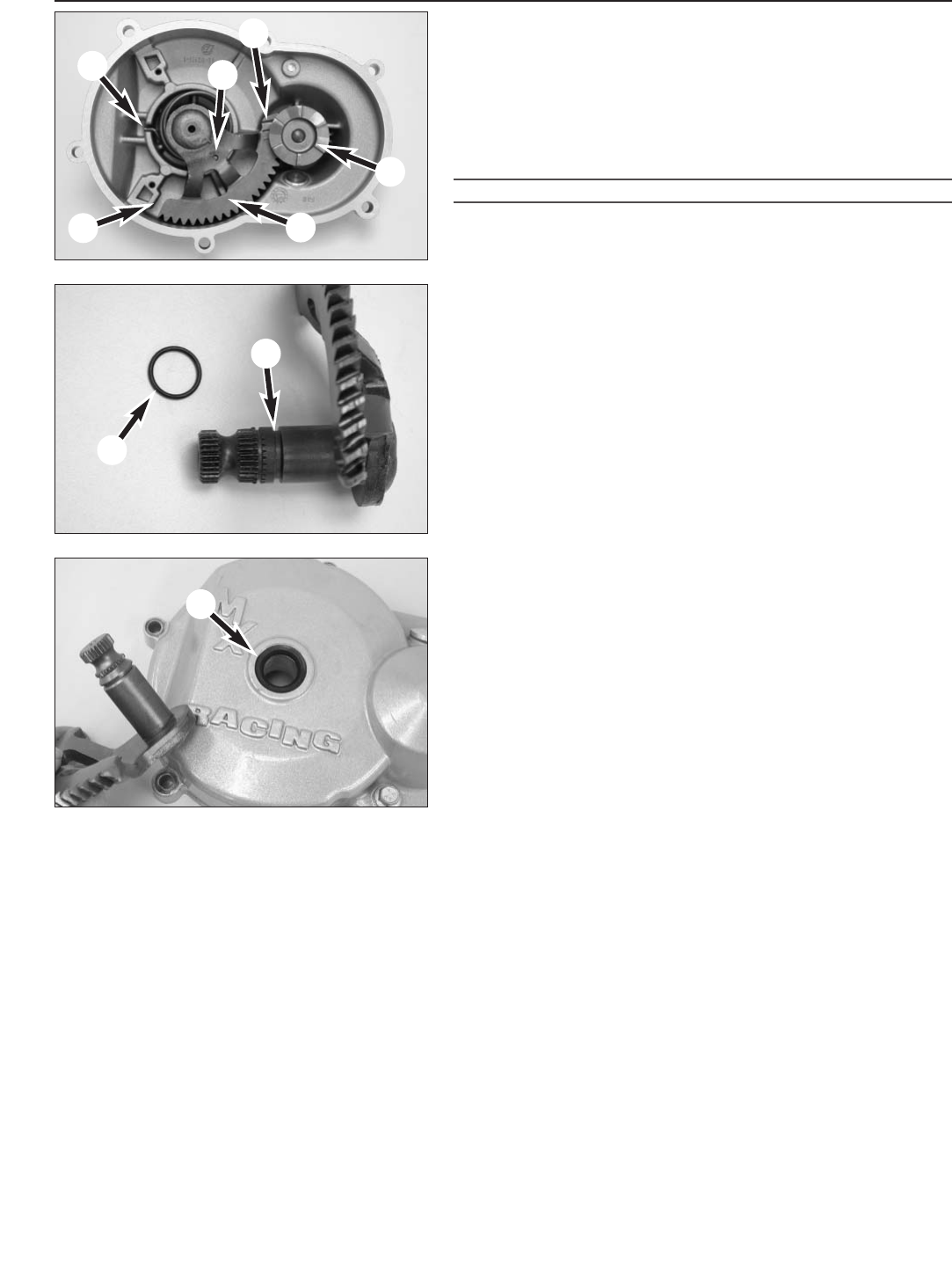
Working on the clutch cover
NOTE: dismantling the clutch cover is neccessary if parts are damaged
or the O-ring is leaking.
– Turn kickstarter shaft 1counter-clockwise and remove ratchet gear
2. Check gearing for wear.
NOTE: If the kickstarter shaft is to be removed, the outer circlip must
be removed, carefully pulling the kickstarter shaft out of the cover.
WARNING
THE KICKSTARTER SPRING IS PRETENSIONED. IT MUST BE STRESS-RELIEVED WHEN
THE KICKSTARTER SHAFT IS PULLED OUT.
– Clean kickstarter shaft and renew O-ring 3(up to the 2003 model).
NOTE:
– make shure that the O-ring is mounted in the second groove 4.
– starting with the 2004 model, a shaft seal ring 5is installed in the
engine instead of an O-ring and the kickstarter shaft no longer has a
second groove. Pry out the old shaft seal ring and press the new
shaft seal ring in until flush with a suitable tool.
During assembly only push the kickstarter shaft into the clutch cover far
enough to be able to reinsert the spring (6and 7). The spring is
pretensioned by turning the kickstarter shaft in a counter-clockwise
direction, then completely push the kickstarter shaft into the clutch
cover. Hold the kickstarter shaft turned, mount the ratchet gear and
release the kickstarter shaft again.
NOTE: the end of the kickstarter shaft gearing has a deformation 8to
prevent the kickstarter shaft from hitting against the clutch cover,
causing it to wedge with the gearing of the ratchet gear. Make sure to
keep a gap between the kickstarter shaft and stop 9.
M
4
6
8
75
32
1
9
5-5E
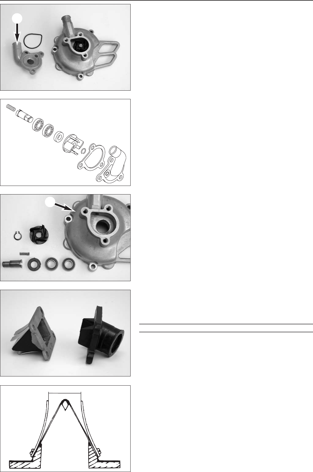
Overhaul the water pump (LC-engine)
– Remove cover 1, discard the O-rings.
– Remove circlip 2with a suitable wrench.
– Remove the water pump wheel 3from the pump shaft 4.
– Press out shaft 4, press out both bearings (6and 7).
– Remove seal shaft ring 5.
NOTE: a spring 8is installed starting with the 2004 model. Remove
before disassembling.
– Press in a new seal shaft ring 5, make shure that the open side of
the seal shaft ring is located on the side of the water pump wheel.
– Slide both new bearings (6and 7) onto the pump shaft 4.
– Lightly grease pump shaft and press the pump shaft with the
bearings in all the way into the ignition cover 9, check for smooth
operation.
– Mount the water pump wheel and the circlip.
– Mount cover 1 with a new O-ring.
– Mount the spring 8(applies to models from 2004), fix in the hole
with a small amount of grease, if necessary.
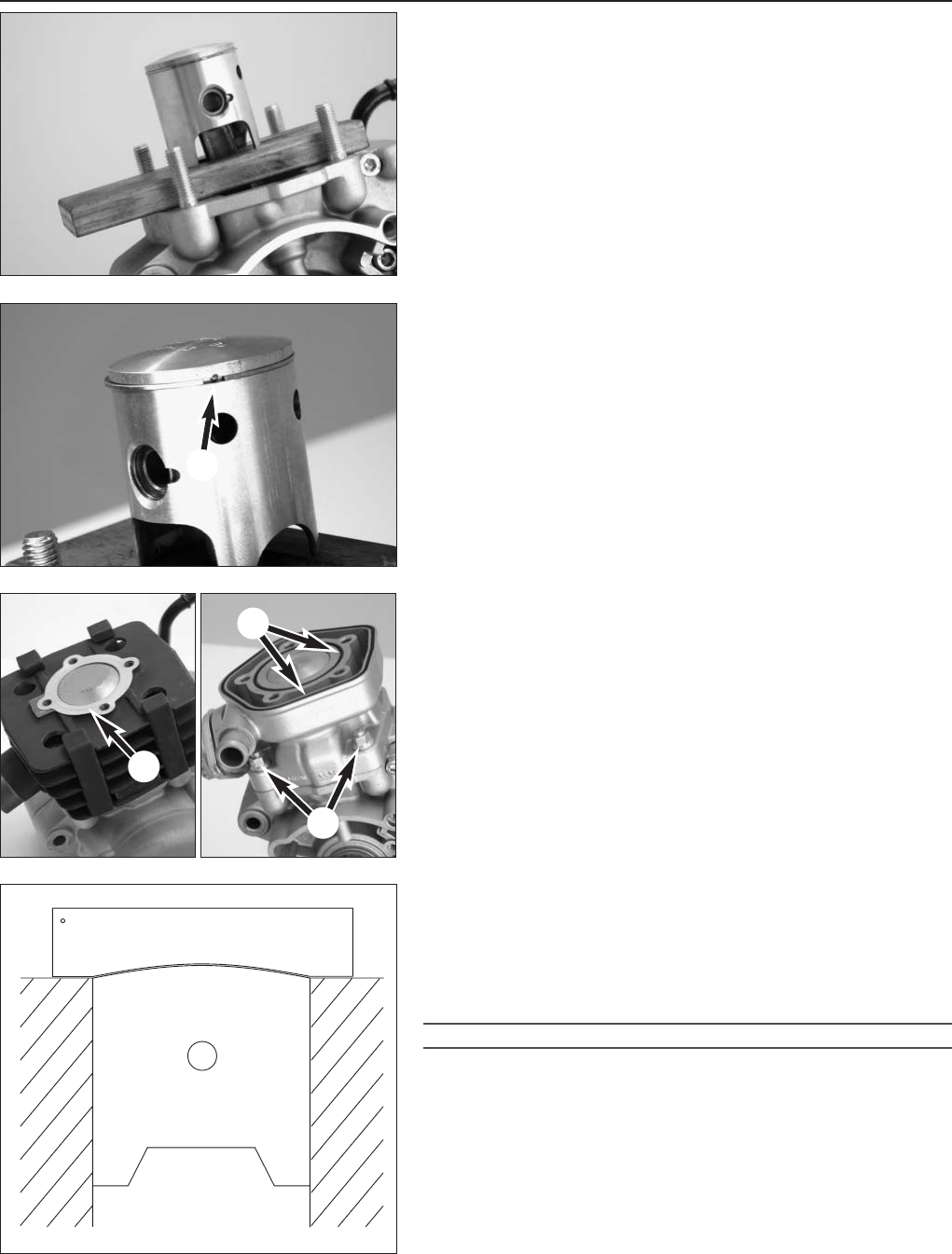
Reed valve housing, intake flange
NOTE: the reed paddles gradually lose their tension, leading to power
loss. Defective or worn reed paddles must be replaced.
If the sealing surfaces of the reed valve housing are also damaged,
replace the entire reed valve housing.
!
CAUTION
!
SECURE ALL BOLTS OF THE DIAPHRAGM HOUSING WITH LOCTITE 243 AFTER
ASSEMBLY.
Intake flange
Check for cracks and other damage.
Reed valve housing
Measure the distance Mbetween the stop plates with a sliding gauge.
If the measured value deviates from the desired value, the stop plates
must be bent accordingly.
Distance M= 17 mm
x
y
10mm
x
y
50mm
5-6E
Repair manual KTM MINI 50 air/liquid cooled Art.-Nr. 3.206.028 -E
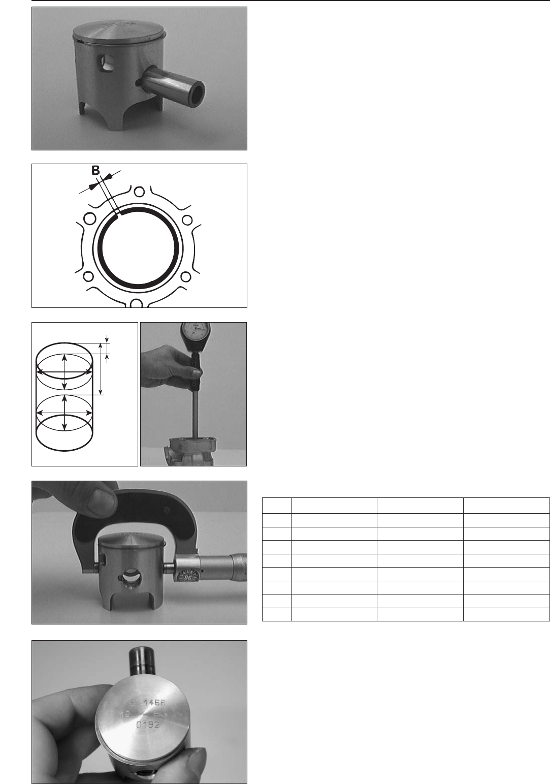
MARK PISTON CYLINDER AC CYLINDER LC
A39.455 - 39.460 mm 39.515 - 39.520 mm 39.505 - 39.510 mm
1.5533 - 1.5535 in 1.5557 - 1.5559 in 1.5553 - 1.5555 in
B39.461 - 39.465 mm 39.521 - 39.525 mm 39.511 - 39.515 mm
1.5535 - 1.5537 in 1.5559 - 1.5561 in 1.5555 - 1.5557 in
C39.466 - 39.470 mm 39.526 - 39.530 mm 39.516 - 39.520 mm
1.5537 - 1.5539 in 1.5561 - 1.5563 in 1.5557 - 1.5559 in
D39.471 - 39.475 mm 39.531 - 39.535 mm 39.521 - 39.525 mm
1.5539 - 1.5541 in 1.55663 - 1.5565 in 1.5559 - 1.5561 in
Check pistons
If continuing to use a used piston, check as follows:
1. Check piston bearing surface for pressure marks, piston seizure (light
friction can be removed with a fine emery stone).
2. The piston ring may not jam in the piston ring groove. To clean the
piston ring groove, use an old piston ring or sanding paper (400
grain size).
3. Piston ring anti-rotation device must fit tightly in the piston and may
not be worn.
4. Check piston ring for wear and gaps in the cylinder.
Measuring the piston ring end gap
– Insert the piston ring in the cylinder and align with the piston
(approx. 10 mm / 0.39 in under the upper edge of the cylinder).
– Measure end gap Bwith a feeler gauge.
End gap: max. 0.20 mm / 0.0078 in
NOTE: If the end gap is larger than specified above, pistons and
cylinder must be checked for wear. If the piston wear and cylinder wear
are within the tolerance zone, the piston ring must be replaced.
Measure the piston and cylinder, determine the piston
– To determine cylinder wear, measure the cylinder 10 mm and 50
mm from the top using a micrometer (shown in the drawing).
– Measure the cylinder diameter in the X and the Y axis to establish
any ovality.
– The piston is measured at the piston skirt, transverse to the piston
pin 32 mm below the top, as shown in the illustration.
– The smallest cylinder diameter minus the largest piston diameter
determines the piston fitting clearance.
Piston fitting clearance AC-engine: 0.055 - 0.065 mm
(0.00216 - 0.00256 in)
LC-engine: 0.045 - 0.055 mm
(0.00177 - 0.00216 in)
NOTE:
When replacing piston and cylinder always make sure to use a piston
and cylinder of the same type. The type identification mark (A to D) can
be found on the cylinder base or the piston head, respectively.
The table to the right indicates the tolerance thresholds for the listed
components.
Always keep in mind that a minimum piston fitting clearance of
0.055 mm (0.00216 in) (AC-engine) or 0.045 mm (0.00117 in)
(LC-engine) is required.
B
A
1
2
3
4
56
7
6
6
5-7E
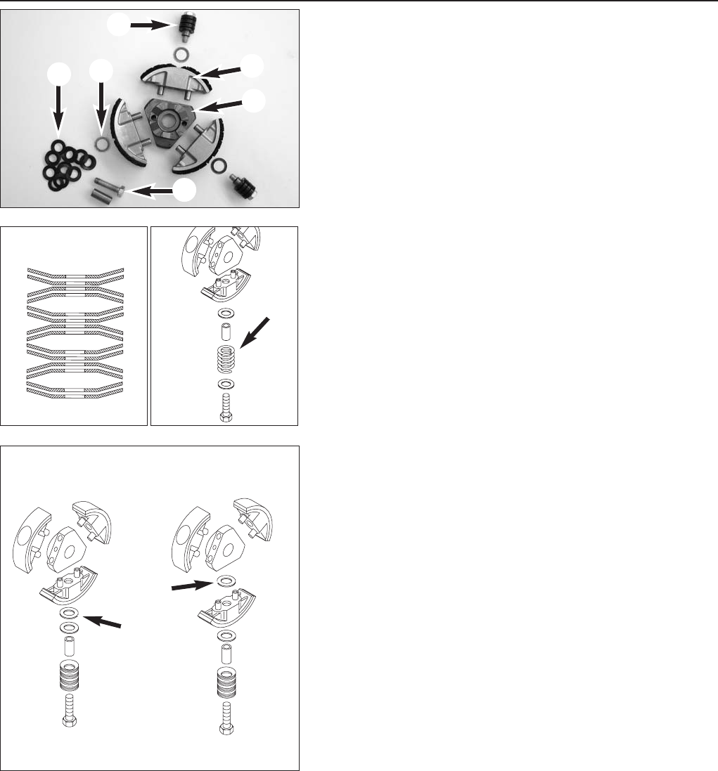
Clutch new used
Balancing the clutch wear
– Check clutch shoes for wear; if the lining only shows minor signs of
wear, the linings can be reinstalled.
NOTE:
– the centrifugal clutch has an outer diameter of approx. 82.5 mm
(3.248 in) when new.
– to compensate for minor wear in the lining, one of the preload
washers 6from any set of springs can be inserted between the
clutch hub and clutch shoes - see Fig. B. If only one washer is
installed, this washer can be used.
– the inner diameter of the clutch drum must not exceed 84.4 mm
(3.3228 in) (new condition 84.0 mm [3.3071 in]).
– Make sure the spring sets are kept free of contamination during
maintenance and repair work to the clutch, otherwise they may
malfunction.
Assembly is in the reverse order as disassembly. HH bolts 1must be
secured with Loctite 243 and tightened to 12 Nm (9 ft.lb).
Overhauling the centrifugal clutch
– Loosen HH bolts 1on the clutch shoes 2and remove together with
the set of springs 3from the clutch hub 4.
NOTE: coilsprings 7are used instead of the spring washers for the
AC-engine. Length of clutch springs: min. 19.6 mm (0.748 in).
– Remove HH bolts with sleeves and set of springs from the clutch
shoes.
NOTE:
– the set of springs consists of 14 spring washers 5, make sure the
spring washers are placed exactly in the same order Ashown below
(only LC-engine).
– Washers 6to pretension the spring sets are located between the
spring sets and the clutch shoes. The preload on the spring set has
an influence on the clutch engagement speed. 0.5 mm more preload
increases the clutch speed by approx. 500 rpm.
– the clutch speed is the speed at which the clutch begins to engage
and the motorcycle begins to move.
– check the clutch speed with the tachometer 451.29.075.000 and
adjust if necessary:
AC-engine: 4000 - 4500 rpm
LC-engine: 8500 - 9000 rpm

6-1E
ASSEMBLING THE ENGINE
Repair manual KTM MINI 50 air/liquid cooled Art.-Nr. 3.206.028-E
MOUNTING THE CRANKSHAFT . . . . . . . . . . . . . . . . . . . . . . . . . . . . . . . . . . . . .6-2
MOUNTING THE PRIMARY DRIVE . . . . . . . . . . . . . . . . . . . . . . . . . . . . . . . . . . .6-2
MOUNTING LEFT ENGINE HOUSING . . . . . . . . . . . . . . . . . . . . . . . . . . . . . . . . . .6-2
IGNITION SYSTEM . . . . . . . . . . . . . . . . . . . . . . . . . . . . . . . . . . . . . . . . . . . . . .6-3
MOUNTING THE CLUTCH . . . . . . . . . . . . . . . . . . . . . . . . . . . . . . . . . . . . . . . . .6-3
MOUNTING THE CLUTCH COVER . . . . . . . . . . . . . . . . . . . . . . . . . . . . . . . . . . . .6-4
IGNITION COVER . . . . . . . . . . . . . . . . . . . . . . . . . . . . . . . . . . . . . . . . . . . . . . .6-4
MOUNTING PISTON . . . . . . . . . . . . . . . . . . . . . . . . . . . . . . . . . . . . . . . . . . . . .6-5
MOUNTING CYLINDER . . . . . . . . . . . . . . . . . . . . . . . . . . . . . . . . . . . . . . . . . . .6-5
ADJUSTING DIMENSION „X“ . . . . . . . . . . . . . . . . . . . . . . . . . . . . . . . . . . . . . . .6-5
CYLINDER HEAD . . . . . . . . . . . . . . . . . . . . . . . . . . . . . . . . . . . . . . . . . . . . . . .6-6
MOUNTING WATERHOSE, INTAKE FLANGE AND IGNITION COIL
. . . . . . . . . . . . . . . .6-6
FILLING IN GEAR OIL . . . . . . . . . . . . . . . . . . . . . . . . . . . . . . . . . . . . . . . . . . . .6-6
INDEX
6
1
2
3
4
56
7
89
bk
bl bl bl
bl
6-2E
Repair manual KTM MINI 50 air/liquid cooled Art.-Nr. 3.206.028 -E
Mounting the crankshaft and output shaft
– Heat the engine case on a heating plate.
– Lubricate both bearings, lightly grease the seal shaft ring.
– Push the output shaft and crankshaft into the bearing.
NOTE: the conrod must be in a vertical position.
!
CAUTION
!
DO NOT INSERT THE SHAFTS INTO THE BEARINGS WITH A HAMMER SINCE THE
BEARINGS AND CRANKSHAFT MAY BE DAMAGED.
Mounting primary drive
– Insert woodruff key 1in the output shaft groove.
– Place the gear of the primary drive on the output shaft, collar 2
first.
– Slide on the nut lock washer.
NOTE: the tab of the lock washer 3must engage in the bore of the
primary drive wheel.
– Bolt nut M14x1,25 into place.
Mounting the left half of the case
– Mount 2 dowels 7x9x10, apply new seal.
NOTE: the seal is not cut until after the second half of the case is
mounted.
– Heat the left half of the case on a heating plate and mount.
– Bolt 7 allan bolts into place.
NOTE: 4, 8and bk are M6x40; 5, 6, 7and 9are M6x35 bolts.
– Tighten 4to 7crosswise to 10 Nm (7 ft.lb).
– Tighten 8to bk to 10 Nm (7 ft.lb).
– Gently tap the case with a plastic hammer a few times near the
bearings to relieve the pretensioning.
– Check both shafts for smooth operation by turning.
– Cut protruding seal bl with a sharp knife for a flush fit.
1
23
4
5
5
6
7
S
89
6-3E
– Wrap insulating tape around the output shaft in the area of the sharp
edge 1to prevent the seal shaft ring from being damaged.
NOTE: wrap insulating tape just above edge to allow the tape to be
easily pulled off after the seal shaft ring is mounted.
– Grease the seal lip and press in the seal shaft ring.
– Pull off the tape.
Mounting the ignition
– Place woodruff key in the crankshaft groove.
– Mount ignition rotor 2with a washer, holding back with special tool,
secure nut with Loctite 243 and tighten to 20 Nm (15 ft.lb).
!
CAUTION
!
THE PINS ON THE SPECIAL TOOL MAY NOT ENGAGE IN THE ROTOR'S THREADED
HOLES, OTHERWISE THE THREAD WILL BE DAMAGED.
– Slide the chain sprocket 3on the output shaft with the collar
towards housing and mount the circlip.
– Mount ignition stator 4in the case.
NOTE: for easier installation, gently press the stator together with your
fingers. Check for a correct fit prior to bolting tight, stator may not
cant.
– Secure allan bolts M5x25 5on the stators with Loctite 243 and
tighten to 8 Nm (6 ft.lb).
– Position cable guide 6.
Mount the clutch
– Slide spacing washer(s) (25x15) onto the crankshaft, mount needle
bearings and the centrifugal clutch unit.
– Block the centrifugal clutch, drum and gear of the primary drive with
a suitable mandrel 7.
– Secure the nut M10x1.25 on the crankshaft with Loctite 243 and
tighten to 35 Nm (25 ft.lb).
– Tighten the output shaft nut to 40 Nm (30 ft.lb).
– Bend over the lock washer on the output shaft nut.
NOTE: for a correct function of the centifugal clutch axial clearance S
between 0,2 and 0,7 mm (0,039 and 0,0055 in) must remain between
the bottom of the drum and the clutch unit.
– Checking the axial clearance with a sliding gauge 8by pressing the
drum against the spacer and measure the distance from the upper
edge of the drum to the drive wheel.Then pull the drum against the
clutch unit, hold in position and measure again - the difference
between these measurements is the axial clearance.
– Press drum against the spacing washers by hand and measure the
distance between the drum and the gear of the primary drive using a
feeler gauge 9- it should be at least 0.5 mm.
NOTE: if the clearances are outside of the tolerance zone, use spacing
washers to balance. Spacing washers are available in different thicknesses.
2
3
2003
1
1
1
1
4
4
4
23
2004
6-4E
Repair manual KTM MINI 50 air/liquid cooled Art.-Nr. 3.206.028 -E
Mounting the clutch cover
– Put new seals in place and mount the clutch cover .
– Bolt clutch cover into place with 6 bolts M6x25 1, tighten the bolts
to 10 Nm (7 ft.lb).
Mount the ignition cover and water pump.
– Put the dowels 7x9x10 in place.
– Align the driving slot on the water pump drive 2with the driver
blade 3on the crankshaft (LC-engine).
NOTE: make sure the spring is mounted in the water pump shaft
(models from 2004).
– Put cover on and engage by turning the pump drive cover back and
forth.
!
CAUTION
!
DO NOT TRY TO MOUNT THE IGNITION COVER BY FORCE, OTHERWISE COMPONENTS
WILL BE DAMAGED.
– Bolt 3 HH bolts M6x25 4into ignition cover and tighten to 10 Nm
(7 ft.lb).
1
3
4
2
6-5E
Mount the pistons
– Fix conrod with a mounting board.
– Grease the conrod bearings and attach to conrod eye.
– Mount pistons, the arrow on the bottom of the piston should point
towards the outlet port.
– Slide piston pin into the conrod eye by hand and mount piston pin
lock with the open side facing down.
– Turn the piston ring until the anti-rotation device engages in the
piston ring end gap 1.
– Mount cylinder base gasket, press piston rings together with your
fingers and slide the greased cylinder over the pistons.
NOTE: if neither the pistons, cylinder, crankshaft or engine case are
being replaced, the same seal thickness can be used as before.
– Tighten collar nut 2on the cylinder base bolting crosswise to a
torque of 18 Nm (13 ft.lb).
– Mount a new seal 3(AC-engine) or insert new O-rings 4in the
recesses (LC-engine).
Adjust measurement „X“
NOTE:
– Measurement „X“ is the distance from the upper piston edge to the
upper cylinder edge, piston set in TDC position and cylinder base
bolts tightened.
– Measurement „X“ must be set with special care, adjusting various
thicknesses of cylinder base gaskets.
!
CAUTION
!
IF THE „X“ MEASUREMENT IS TOO LARGE-THIS MEANS THAT A GAP IS VISIBLE
BETWEEN PISTON AND ADJUSTING PLATE-THE COMPRESSION WILL SINK AND THE
ENGINE WILL LOSE POWER. IF THE „X“ MEASUREMENT IS TOO SMALL-THIS MEANS
THAT A GAP IS VISIBLE BETWEEN CYLINDER AND ADJUSTING PLATE-THE ENGINE WILL
PING AND OVERHEAT.
– Place the adjusting plate on the cylinder and set pistons to TDC (see
diagram). If the „X“ measurement is correctly adjusted, the feeler
gauge will lie flush on the pistons and on the cylinder.
– Adjust the „X“ measurement by adding or removing cylinder base
gaskets.
NOTE: the „X“ measurement is increased by adding cylinder base
gaskets and decreased by removing cylinder base gaskets.
11
2
3
4
6-6E
Repair manual KTM MINI 50 air/liquid cooled Art.-Nr. 3.206.028 -E
Mount the cylinder head
– Mount the cylinder head 1, making sure the water connection is on
the intake side (LC-engine).
– Use new washers for the cylinder head bolts (LC-engine), tighten
cylinder head bolts crosswise in 2 stages to 15 Nm (11 ft.lb).
Mount water hose, intake flange and ignition coil
– Apply water hose and tighten hose clamp (only LC-engine).
– Mount the reed valve housing and intake flange with new seal.
NOTE:
– the longer bolts (M6x40) 2are bolted into the upper holes, the
bracket and the ground connection of the ignition coil are also fixed
with these bolts.
– the shorter bolts (M6x20) 3are bolted into the lower holes.
– the intake flange should point to the chain sprocket.
– Bolt in the spark plug, spark plug cap and ignition connection,
mount kickstarter and transmission vent hose.
Fill in transmission oil
– Make sure the transmission drain plug is tightened to 15 Nm
(11 ft.lb).
– Remove oil filler bolt 4and add 150-200 ccm gear oil Dexron II
(Motorex ATF Super), remount oil filler bolt and tighten to 5 Nm
(4 ft.lb).

7-1E
Repair manual KTM MINI 50 air/liquid cooled Art.-Nr. 3.206.028-E
TROUBLE SHOOTING
TROUBLE SHOOTING 50 AC/LC . . . . . . . . . . . . . . . . . . . . . . . . . . . . . . . . . . . . .7-2
IGNITION MEASUREMENT 50 AC/LC . . . . . . . . . . . . . . . . . . . . . . . . . . . . . . . . .7-4
MEASUREMENT WITH PEAK VOLTAGE ADAPTER . . . . . . . . . . . . . . . . . . . . . . . .7-4
7
INDEX

7-2E
Repair manual KTM MINI 50 air/liquid cooled Art.-Nr. 3.206.028 -E
TROUBLE CAUSE REMEDY
Engine fails to start Operating error Open fuel tap, replenish fuel, do not use choke
Fuel supply interrupted Close fuel tap, loosen fuel hose at carburettor, lead into a
basin and open fuel tap,
– if fuel leaks out, clean carburettor
– if no fuel leaks out, check tank ventilation, i.e. clean
fuel tap
Electrode distance too large Reduce electrode distance (0.60 mm) (0.0236 in)
Plug fouled by oil, wet or bridged Clean spark plug or renew
Ignition wire or spark plug
connector damaged
Dismount spark plug, connect ignition cable, hold to
ground (blank place on engine) and actuate kickstarter, a
strong spark must be produced at the spark plug
– If no spark is produced, loosen spark plug cap from
ignition cable, hold about 5 mm from ground and
actuate kickstarter
– If a spark now occurs, replace spark plug cap
– If no spark is produced, control ignition system
Kill button wire or short-circuit
switch faulty
Disconnect black coloured cable from short circuit button
at ignition coil and check ignition spark. If the spark is
O.K. repair defective part of cable or ignition switch
Loose ignition cable connectors Inspect cable connectors
Spark too weak Examine ignition system
Water in the carburetor and jets
blocked
Dismantle and clean carburetor
Engine without idle running Idle adjusting bolt out of
adjustment
Readjust idle running or replace idle adjusting bolt
Ignition system damaged Examine ignition system
Wear Overhaul engine
Less power of engine Air filter obstructed Clean or renew airfilter
Fuel supply partly interrupted or
blocked
Blow through fuel pipe and clean carburetor
Loss of compression due to loose
spark plug
Tighten spark plug
Exhaust system damaged Check exhaust system for damage
Engine has not enough
preignition
Check and adjust ignition
Reed paddles tensionless or
damaged, surface of reed valve
housing damaged
Replace reed paddles or reed valve housing
Wear Overhaul engine

7-3E
TROUBLE CAUSE REMEDY
Engine stalling or running
with four stroke cycle
Carburetor overflows if level
adjust too high, float needle
seating is dirty or enlarged
Clean carburetor, if necessary replace float needle and
adjust level
Loose carburetor jets Tighten jets
High rpm misfiring Incorrect heat range spark plug
or low quality spark plug
Refer to technical data section
Loose, corroded or non conductive
ignition socket connector
Check and seal with silicon
Engine spluters into the
carburetor
Lack of fuel Clean fuel pipes, examine tank aeration and clean
Spark plug with incorrect heat value
(Ignition by incandescence)
Fit correct spark plug
Engine takes air out of control Check intake flange and carburettor if firmly setted
Engine overheating Insufficient liquid in cooling
system
(only LC-engine)
Top up coolant and bleed cooling system check cooling
system for leaks
Radiator fins clogged
(only LC-engine)
Clean radiatar fins with water jet
Frothing in cooling system
(only LC-engine)
Renew coolant using branded anti-freeze/anti-corrosive
(Motorex Anti-Freeze)
Pinched or kinked water hoses
(only LC-engine)
Replace with correct routed hoses
Incorrect ignition timing because
of loose stator bolts
Readjust to correct ignition timing specifications, secure
bolts with Loctite 243
Incorrect compression ratio Measure and adjust compression ratio
Emission of white smoke
(steam)
(only LC-engine)
Cylinder head or O-ring of
cylinder head gasket leaks
Check cylinder head, replace O-ring
Excessive oil escapes from
transmission breather tube
Excessive oil quantity in
transmission
Correct transmission oil level
1
2
R
S
7-4E
Repair manual KTM MINI 50 air/liquid cooled Art.-Nr. 3.206.028 -E
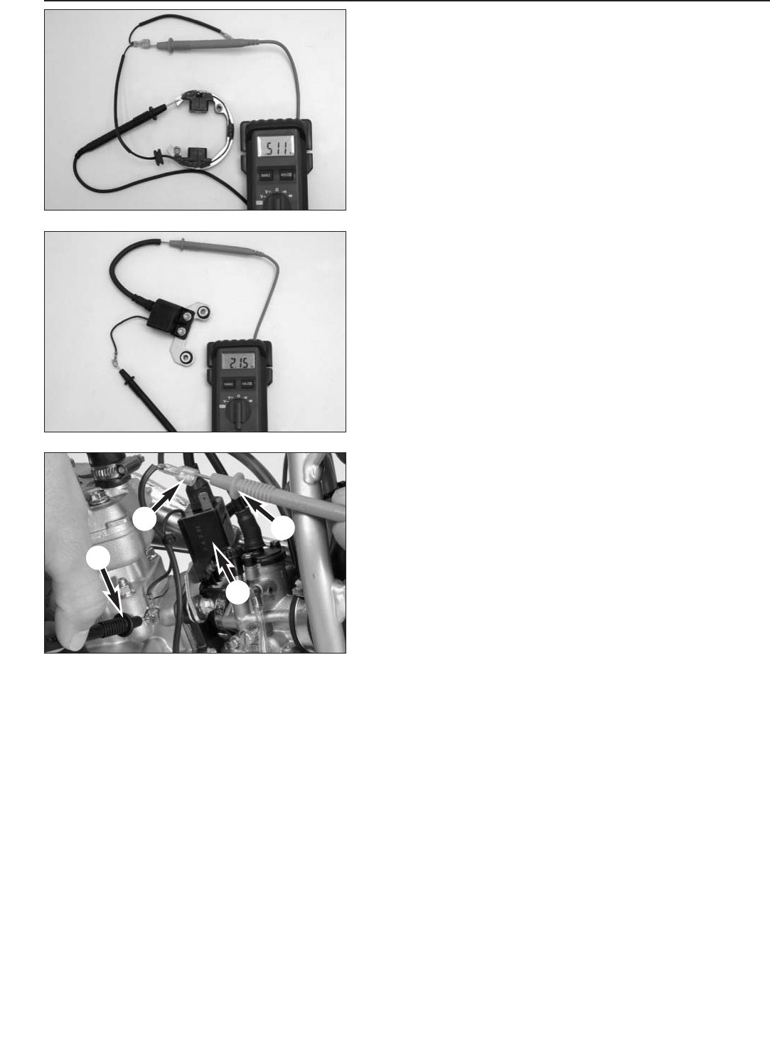
Resistor values of the ignition system - Stator
– Unplug the ignition stator and measure the resistance of the stator
using a digital measuring tool.
– The resistance must be 500 Ω± 40 Ωat 20º C.
NOTE: it is not neccessary to take the stator out of the engine housing.
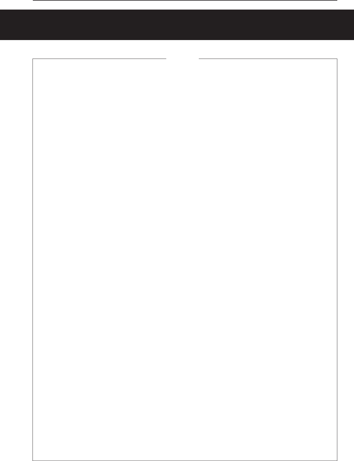
Ignition coil
– Undo the spark plug cap
– Measure the resistor of the secundary side of the Ignition coil
between high tension lead and mass of the coil.
– The resistance must be 2250 Ω± 250 Ωat 20º C.
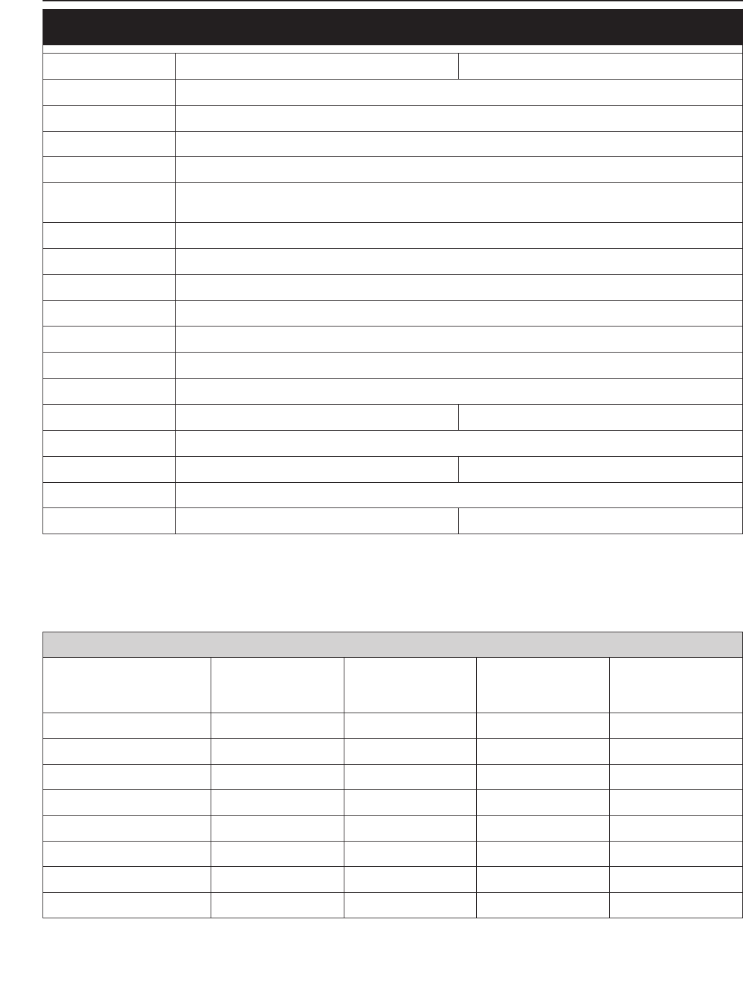
Measuring static ignition values with peak voltage adapter
Measuring conditions:
– cold engine
– seat and tank removed
– all connector and socket connectors and the ground connection in a
non-corroding condition
– kick the kick starter forcefully at least 5 times for each measurement
Check the pulse generator/charging coil for an output signal - one-pin
connector 1:
– Apply the red measuring lead Rof the peak voltage adapter to the
connector and the black measuring lead Sto the ground, disconnect
connector 1from the ignition coil 2
Multimeter display for 50 SX AC: 220 Volt ± 10 Volt
Multimeter display for 50 SX LC: 270 Volt ±10 Volt
– Same measurement with connector connected to the ignition coil
Multimeter display for 50 SX AC: 250 Volt ±10 Volt
Multimeter display for 50 SX LC: 270 Volt ±10 Volt
8-1E
MODEL 2002
ENGINE . . . . . . . . . . . . . . . . . . . . . . . . . . . . . . . . . . . . . . . . . . . . . . . . . . . . . .8-3
BASIC CARBURETOR SETTING . . . . . . . . . . . . . . . . . . . . . . . . . . . . . . . . . . . . .8-3
CHASSIS . . . . . . . . . . . . . . . . . . . . . . . . . . . . . . . . . . . . . . . . . . . . . . . . . . . .8-4
STANDARD-ADJUSTMENT – FORK . . . . . . . . . . . . . . . . . . . . . . . . . . . . . . . . . . .8-4
STANDARD ADJUSTMENT – SHOCK ABSORBER . . . . . . . . . . . . . . . . . . . . . . . . .8-4
MODEL 2003
ENGINE . . . . . . . . . . . . . . . . . . . . . . . . . . . . . . . . . . . . . . . . . . . . . . . . . . . . . .8-5
BASIC CARBURETOR SETTING . . . . . . . . . . . . . . . . . . . . . . . . . . . . . . . . . . . . .8-5
CHASSIS . . . . . . . . . . . . . . . . . . . . . . . . . . . . . . . . . . . . . . . . . . . . . . . . . . . .8-6
STANDARD-ADJUSTMENT – FORK . . . . . . . . . . . . . . . . . . . . . . . . . . . . . . . . . . .8-6
STANDARD ADJUSTMENT – SHOCK ABSORBER . . . . . . . . . . . . . . . . . . . . . . . . .8-6
MODEL 2004
ENGINE . . . . . . . . . . . . . . . . . . . . . . . . . . . . . . . . . . . . . . . . . . . . . . . . . . . . . .8-7
BASIC CARBURETOR SETTING . . . . . . . . . . . . . . . . . . . . . . . . . . . . . . . . . . . . .8-8
CHASSIS . . . . . . . . . . . . . . . . . . . . . . . . . . . . . . . . . . . . . . . . . . . . . . . . . . . .8-9
STANDARD-ADJUSTMENT – FORK . . . . . . . . . . . . . . . . . . . . . . . . . . . . . . . . . . .8-9
STANDARD ADJUSTMENT – SHOCK ABSORBER . . . . . . . . . . . . . . . . . . . . . . . . .8-9
Repair manual KTM MINI 50 air/liquid cooled Art.-Nr. 3.206.028-E
INDEX
TECHNICAL SPECIFICATIONS 8

8-2E
MODEL 2005 AC
ENGINE . . . . . . . . . . . . . . . . . . . . . . . . . . . . . . . . . . . . . . . . . . . . . . . . . . . . .8-10
BASIC CARBURETOR SETTING . . . . . . . . . . . . . . . . . . . . . . . . . . . . . . . . . . . .8-10
CHASSIS . . . . . . . . . . . . . . . . . . . . . . . . . . . . . . . . . . . . . . . . . . . . . . . . . . .8-11
STANDARD-ADJUSTMENT – FORK . . . . . . . . . . . . . . . . . . . . . . . . . . . . . . . . . .8-11
STANDARD ADJUSTMENT – SHOCK ABSORBER . . . . . . . . . . . . . . . . . . . . . . . .8-11
MODEL 2005 LC
ENGINE . . . . . . . . . . . . . . . . . . . . . . . . . . . . . . . . . . . . . . . . . . . . . . . . . . . . .8-12
BASIC CARBURETOR SETTING . . . . . . . . . . . . . . . . . . . . . . . . . . . . . . . . . . . .8-12
CHASSIS . . . . . . . . . . . . . . . . . . . . . . . . . . . . . . . . . . . . . . . . . . . . . . . . . . .8-13
STANDARD-ADJUSTMENT – FORK . . . . . . . . . . . . . . . . . . . . . . . . . . . . . . . . . .8-13
STANDARD ADJUSTMENT – SHOCK ABSORBER . . . . . . . . . . . . . . . . . . . . . . . .8-13
MODEL 2006 AC
ENGINE . . . . . . . . . . . . . . . . . . . . . . . . . . . . . . . . . . . . . . . . . . . . . . . . . . . . .8-14
BASIC CARBURETOR SETTING . . . . . . . . . . . . . . . . . . . . . . . . . . . . . . . . . . . .8-14
CHASSIS . . . . . . . . . . . . . . . . . . . . . . . . . . . . . . . . . . . . . . . . . . . . . . . . . . .8-15
STANDARD-ADJUSTMENT – FORK . . . . . . . . . . . . . . . . . . . . . . . . . . . . . . . . . .8-15
STANDARD ADJUSTMENT – SHOCK ABSORBER . . . . . . . . . . . . . . . . . . . . . . . .8-15
MODEL 2006 LC
ENGINE . . . . . . . . . . . . . . . . . . . . . . . . . . . . . . . . . . . . . . . . . . . . . . . . . . . . .8-16
BASIC CARBURETOR SETTING . . . . . . . . . . . . . . . . . . . . . . . . . . . . . . . . . . . .8-16
CHASSIS . . . . . . . . . . . . . . . . . . . . . . . . . . . . . . . . . . . . . . . . . . . . . . . . . . .8-17
STANDARD-ADJUSTMENT – FORK . . . . . . . . . . . . . . . . . . . . . . . . . . . . . . . . . .8-17
STANDARD ADJUSTMENT – SHOCK ABSORBER . . . . . . . . . . . . . . . . . . . . . . . .8-17
TOLERANCES AND FITTING CLEARANCES . . . . . . . . . . . . . . . . . . . . . . . . . . . .8-18
TIGHTENING TORQUES - ENGINE . . . . . . . . . . . . . . . . . . . . . . . . . . . . . . . . . . .8-18
TIGHTENING TORQUES - CHASSIS . . . . . . . . . . . . . . . . . . . . . . . . . . . . . . . . .8-18
INDEX
Repair manual KTM MINI 50 air/liquid cooled Art.-Nr. 3.206.028-E
8-3E
Repair manual KTM MINI 50 air/liquid cooled Art.-Nr. 3.206.028 -E
TECHNICAL DATA - ENGINE 50 AC/LC 2002
Engine 50 AC (aircooled) 50 LC (liquid cooled)
Design single cylinder 2-stroke engine, with reed valve inlet
Displacement 49,0 cm³
Bore/Stroke 39,5 / 40 mm
Fuel SUPER fuel, research octane no 95, mixed with 2-stroke oil
Oil/gasoline ratio 1 : 40 when using high grade 2-stroke oil (Shell Advance Racing X)
When in doubt, please contact your importer or use 1 : 33 mix ratio to be on the safe side
Lubrication mixture lubrication
Crankshaft bearing 2 grooved ball bearing
Connecting rod bearing needle bearing
Piston pin bearing needle bearing
Piston rings 1 rectangular ring
Primary drive straight cut spur gears, 16 : 57 t
Transmission oil 0.15-0.2 liter gear oil Dexron II (Shell Donax TA)
Spark plug NGK BR 8 EH NGK BR 10 EG
Electrode gap 0,6 mm
Carburetor Dell'Orto PHVA 14 DS Dell'Orto PHVA 14 DS / PHBG 19 BS
Air filter wet foam type air filter insert
Coolant –0.5 liter (0.132 USgal); water : coolant = 2 : 1
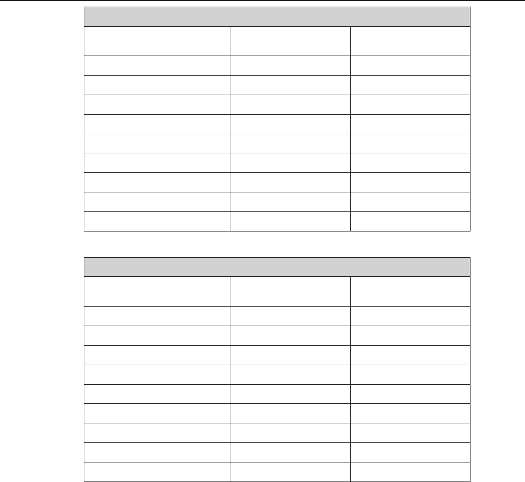
BASIC CARBURETOR SETTING
Model
Type
50 MINI ADVENTURE
Dell'Orto PHVA 14 DS
50 JUNIOR/SENIOR
ADVENTURE
Dell'Orto PHVA 14 DS
50 SX PRO JUNIOR LC
Dell'Orto PHVA 14 DS
50 SX PRO SENIOR LC
Dell'Orto PHBG 19 BS
Main jet 60 (70/80) 80 (70) 80 85
Needle jet 211 FA 211 FA 211 FA 260 AU
Idling jet 45 45 45 48
Jet needle A10 A10 A10 W9
Needle position from top 3. 3. 3. 3.
Air/Mixture reg. screw open 3,5 3,5 3,5 3,0
Slide 40 40 40 60
Starting jet 60 60 60 60
8-4E
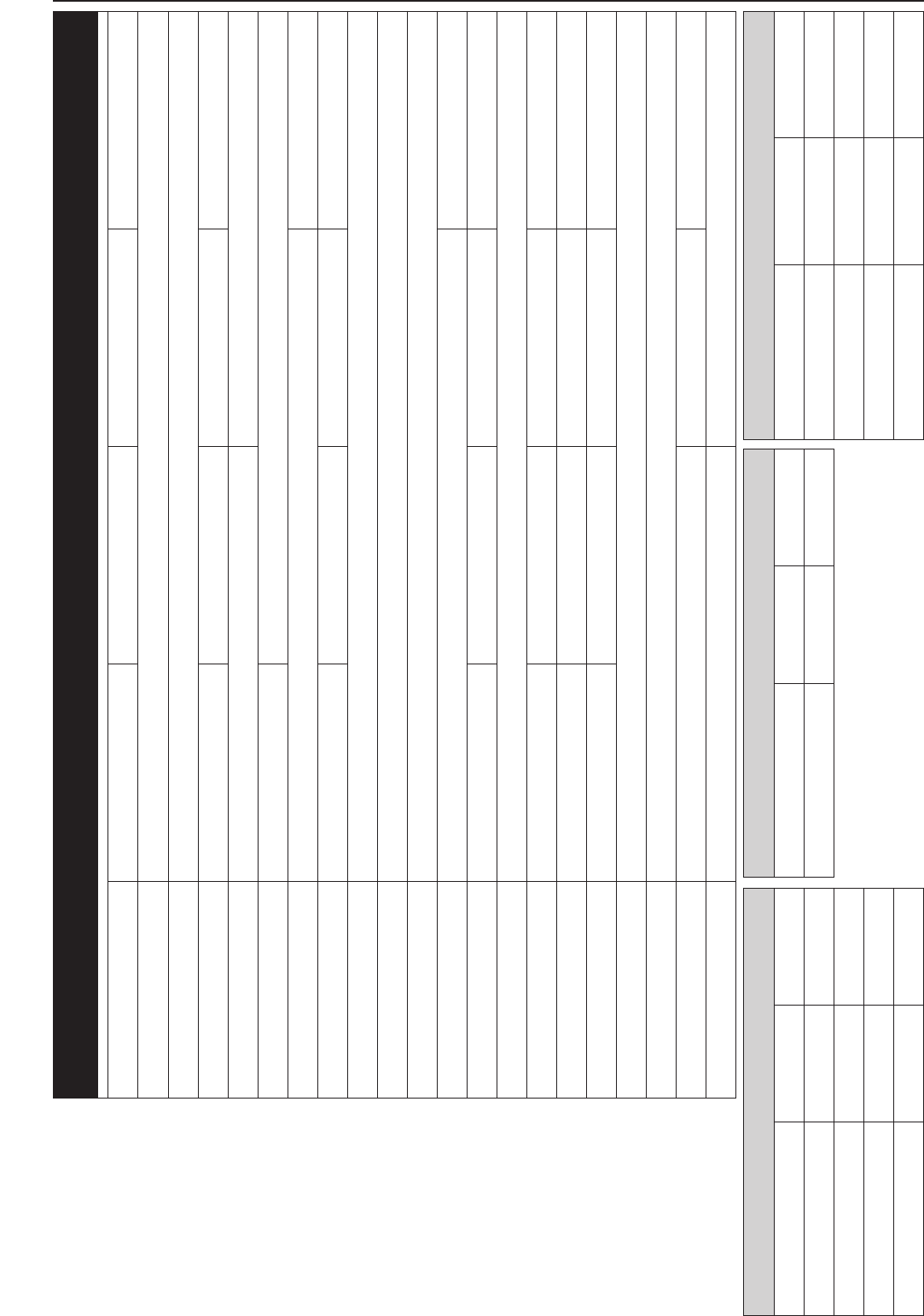
TECHNICAL SPECIFICATIONS - CHASSIS 50 MINI 2002
50 SX PRO SENIOR LC
single downtube, split-cradle
Marzocchi Ø = 32 mm
175/185 mm (6.9/7.3 in)
Central shock absorber WP PDS
Disc brake Ø 160 mm (6.3 in)
Drumbrake Ø 90 mm (3.5 in)
front/rear 2.50x10" Pirelli MT 32 / 2.75x10" MT 320
front/rear: 1.0 bar / 1.0 bar
1,8 Liter
11 : 48
1/2x3/16" 104 rolls
64°
1030 mm (40 in)
650/675 mm (adjustable) (25.6/26.6 in)
255 mm (10 in)
40 kg (88lbs)
max. 130 cm (5.1 in)
max. 35 kg (78 lbs)
7 - 8 years
50 LC
50 SX PRO JUNIOR LC
135/200 mm (5.3/7.8 in)
1/2x3/16" 96 rolls
63°
914 mm (36 in)
615 mm (24.2 in)
220 mm (8.6 in)
50 SENIOR ADVENTURE
175/190 mm (6.9/7.5 in)
Central shock absorber Paioli MC30
Drum brake Ø 90 mm (3.5 in)
front/rear 2.50x10" VRM-140
1/2x3/16" 104 rolls
64°
1030 mm (40 in)
650/675 mm (adjustable)(25.6/26.6 in)
255 mm (10 in)
4 - 6 years
50 AC
50 JUNIOR ADVENTURE
135/234 mm (5.3/9.2 in)
1/2x3/16" 96 rolls
63°
914 mm (36 in)
615 mm (24.2 in)
220 mm (8.6 in)
50 MINI ADVENTURE
115/185 mm (4.5/7.3 in)
62°
910 mm (35.8 in)
590 mm (23.2 in)
190 mm (7.5 in)
Frame
Fork
Wheel travel front/rear
Rear suspension
Front brake
Rear brake
Tyres
Tire pressure
Fuel tank capacity
Final drive ratio
Chain
Steering angle
Wheel base
Seat height, unloaded
Ground clearance
Dead weight without fuel
Rider's body height
Rider's body weight
Recommended age of rider
Engine
STANDARD-ADJUSTMENT - FORK
50 LC
2,0 N/mm
10 mm (0.4 in)
SAE 7,5
110 mm (4.3 in)
50 AC
2,0 N/mm
10 mm (0.4 in)
SAE 7,5
110 mm (4.3 in)
Spring
Preload
Fork oil
Luftkammerlänge
STANDARD ADJUSTMENT - SHOCK ABSORBER
WP 0318W911
5
45 N/mm
7 mm/0.3 in
WP 0318W910
5
85 N/mm
7 mm/0.3 in
Rebound adjuster
Spring
Spring preload
8-5E
Repair manual KTM MINI 50 air/liquid cooled Art.-Nr. 3.206.028 -E
TECHNICAL DATA - ENGINE 50 AC/LC 2003
Engine 50 AC (aircooled) 50 LC (liquid cooled)
Design single cylinder 2-stroke engine, with reed valve inlet
Displacement 49,0 cm³
Bore/Stroke 39,5 / 40 mm
Fuel SUPER fuel, research octane no 95, mixed with 2-stroke oil (separate lubrication only ROZ 95)
Oil/gasoline ratio 1 : 40 when using high grade 2-stroke oil (Shell Advance Racing X)
(separate lubrication Shell Advance Ultra 2)
Lubrication mixture lubrication / separate lubrication
Crankshaft bearing 2 grooved ball bearing
Connecting rod bearing needle bearing
Piston pin bearing needle bearing
Piston rings 1 rectangular ring
Primary drive straight cut spur gears, 16 : 57 t
Transmission oil 0.15-0.2 liter gear oil Dexron II (Shell Donax TA)
Spark plug NGK BR 8 ECM
Electrode gap 0,6 mm (0.0236 in)
Carburetor Dell'Orto PHVA 14 DS / 12 XS Dell'Orto PHVA 14 DS / PHBG 19 BS
Air filter wet foam type air filter insert
Coolant –0.5 liter (0.132 USgal) ; water : coolant = 2 : 1
BASIC CARBURETOR SETTING
Model
Type
50 MINI ADVENTURE
(Separate lubrication)
Dell'Orto PHVA 12 XS
50 JUNIOR/SENIOR
ADVENTURE
Dell'Orto PHVA 14 DS
50 SX PRO JUNIOR LC
Dell'Orto PHVA 14 DS
50 SX PRO SENIOR LC
Dell'Orto PHBG 19 BS
Main jet 60 80 (70) 80 85
Needle jet 211 FA 211 FA 211 FA 260 AU
Idling jet 38 45 45 48
Jet needle A10 A10 A10 W9
Needle position from top 4. 3. 3. 3.
Air/Mixture reg. screw open 43,5 3,5 3,0
Slide 40 40 40 60
Starting jet 60 60 60 60

8-6E
TECHNICAL SPECIFICATIONS - CHASSIS 50 MINI 2003
50 SX PRO SENIOR LC
single downtube, split-cradle
Marzocchi Ø = 32 mm
175/185 mm (6.9/7.3 in)
Central shock absorber WP PDS
Disc brake Ø 160 mm (6.3 in)
Drumbrake Ø 90 mm (3.5 in)
2.50x12" VeeRubber V270/ 2.75x10"V271
front/rear: 1.0 bar / 1.0 bar
1,8 Liter
11 : 48
1/2x3/16" 104 rolls
64°
1030 mm (40 in)
650/675 mm (adjustable)
(25.6/26.6 in)
255 mm (10 in)
max. 130 cm (5.1 in)
max. 35 kg (78 lbs)
6 - 10 years
50 LC
50 SX PRO JUNIOR LC
135/200 mm (5.3/7.8 in)
2.50x10" Pirelli MT 32 / 2.75x10"MT320
1/2x3/16" 96 rolls
63°
914 mm (36 in)
590/615 mm (adjustable)
(23.2/24.2 in)
220 mm (8.6 in)
50 SENIOR ADVENTURE
175/190 mm (6.9/7.5 in)
Central shock absorber Paioli MC30
Drum brake Ø 90 mm (3.5 in)
2.50x10" VRM-140
1/2x3/16" 104 rolls
64°
1030 mm (40 in)
650/675 mm (adjustable)
(25.6/26.6 in)
255 mm (10 in)
4 - 6 years
50 AC
50 JUNIOR ADVENTURE
135/234 mm (5.3/9.2 in)
1/2x3/16" 96 rolls
63°
914 mm (36 in)
615/640 mm (adjustable)
(24.2/25.2 in)
220 mm (8.6 in)
50 MINI ADVENTURE
115/185 mm (4.5/7.3 in)
62°
910 mm (35.8 in)
590/615 mm (adjustable)
(23.2/24.2 in)
190 mm (7.5 in)
Frame
Fork
Wheel travel front/rear
Rear suspension
Front brake
Rear brake
Tyres front/rear
Tire pressure
Fuel tank capacity
Final drive ratio
Chain
Steering angle
Wheel base
Seat height, unloaded
Ground clearance
Rider's body height
Rider's body weight
Recommended age of rider
Engine
STANDARD-ADJUSTMENT - FORK
50 LC
2,0 N/mm
10 mm (0.4 in)
SAE 7,5
110 mm (4.3 in)
50 AC
2,0 N/mm
10 mm (0.4 in)
SAE 7,5
(4.3 in)110 mm
Spring
Preload
Fork oil
Air chamber lenght
STANDARD ADJUSTMENT - SHOCK ABSORBER AC
50 SENIOR
Adventure
12 mm/0.47 in
50 JUNIOR
Adventure
8 mm/0.31 inSpring preload
STANDARD ADJUSTMENT - SHOCK ABSORBER
WP 0318W911
5
45 N/mm
7 mm/0.3 in
WP 0318W910
5
85 N/mm
7 mm/0.3 in
Rebound adjuster
Spring
Spring preload
8-7E
Repair manual KTM MINI 50 air/liquid cooled Art.-Nr. 3.206.028 -E
TECHNICAL DATA - ENGINE 50 AC/LC 2004
50 SX PRO SENIOR LC
single cylinder 2-stroke engine, with reed valve inlet
49,0 cm³
39,5 / 40 mm
Lead-free SUPER FUEL (ROZ 95), mixed with 2-stroke oil
1 : 40 when using high grade 2-stroke oil (Motorex 2T Cross Power)
When in doubt, please contact your importer or use 1 : 33 mix ratio to be on the safe side
high-grade two-stroke oils
for mixture lubrication
Motorex Cross Power 2T
2 grooved ball bearing
needle bearing
needle bearing
1 rectangular ring
straight cut spur gears, 16 : 57 Z
0.15-0.2 liter gear oil Dexron II (Motorex ATF Super)
NGK BR 8 ECM
0,6 mm
Dell'Orto PHBG 19 BS
wet foam type air filter insert
0.5 litres, 40% antifreeze, 60% water, at least -25 °C
50 SX PRO JUNIOR LC
Dell'Orto PHVA 14 DS
SENIOR AC (mixture lubrication)
–
MINI AC (separate lubrication)
Lead-free SUPER FUELf (ROZ 95)
–
high-grade two-stroke oils
for separate lubrication
Motorex Cross Power 2T
Dell'Orto PHVA 12 XS
Engine
Design
Displacement
Bore/Stroke
Fuel
Oil/gasoline ratio
Oil
Crankshaft bearing
Connecting rod bearing
Piston pin bearing
Piston rings
Primary drive
Transmission oil
Spark plug
Electrode gap
Carburetor
Air filter
Cooling liquid
8-8E
BASIC CARBURETOR SETTING
Model 50 MINI ADVENTURE
(SEPARATE LUBRICATION)
50 SENIOR ADVENTURE
(MIXTURE LUBRICATION)
Type Dell'Orto PHVA 12 XS Dell'Orto PHVA 14 DS
Main jet 60 80 (70)
Needle jet 211 FA 211 FA
Idling jet 38 45
Jet needle A10 A10
Needle position from top 4. 3.
Air/Mixture reg. screw open 43,5
Slide 40 40
Starting jet 60 60
BASIC CARBURETOR SETTING
Model 50 SX PRO JUNIOR LC 50 SX PRO SENIOR LC
Type Dell'Orto PHVA 14 DS Dell'Orto PHBG 19 BS
Main jet 80 85
Needle jet 211 FA 211 FA
Idling jet 45 48
Jet needle A10 W9
Needle position from top 3. 3.
Air/Mixture reg. screw open 3,5 3,0
Slide 40 60
Starting jet 60 60
8-9E
Repair manual KTM MINI 50 air/liquid cooled Art.-Nr. 3.206.028 -E
TECHNICAL SPECIFICATIONS - CHASSIS 50 MINI 2004
50 SX PRO SENIOR LC
single downtube, split-cradle
Marzocchi Ø = 32 mm
185/185 mm
Central shock absorber WP PDS
Disk brake Ø 160 mm
Disk brake Ø 140 mm
2.50x12" Pirelli MT 32A
2.75x10" Pirelli MT320
1,0 bar / 1,0 bar
1,8 Liter
11 : 44
1/2x3/16" 104 rolls
66°
1030 mm
650/675 mm (adjustable)
255 mm
max. 130 cm
max. 35 kg
6 - 10 years
50 LC
50 SX PRO JUNIOR LC
140/205 mm
Drum brake Ø 90 mm
2.50x10" Pirelli MT32A
11 : 48
1/2x3/16" 96 rolls
910 mm
585/610 mm (adjustable)
220 mm
4 - 7 years
50 SENIOR ADVENTURE
175/190 mm
Central shock absorber Paioli
2.50x12" Pirelli MT 32A
1/2x3/16" 104 rolls
1030 mm
650/675 mm (adjustable)
255 mm
4 - 6 years
50 AC
50 MINI ADVENTURE
115/185 mm
Drum brake Ø 90 mm
2.50x10" Pirelli MT32A
1/2x3/16" 96 rolls
910 mm
590/615 mm (adjustable)
190 mm
Frame
Fork
Wheel travel front/rear
Rear suspension
Front brake
Rear brake
Tires front
Tires rear
Tire pressure front/rear
Fuel tank capacity
Final drive ratio
Chain
Steering angle
Wheel base
Seat height, unloaded
BGround clearance, unloaded
Rider's body height
Rider's body weight
Recommended age of rider
Engine
STANDARD-ADJUSTMENT - FORK
50 LC
2,0 N/mm
10 mm (0.4 in)
SAE 7,5
110 mm (4.3 in)
50 AC
2,0 N/mm
10 mm (0.4 in)
SAE 7,5
110 mm (4.3 in)
Spring
Preload
Fork oil
Air chamber lenght
STANDARD ADJUSTMENT - SHOCK ABSORBER AC
50 SENIOR
12 mm/0.47 in
50 MINI
8 mm/0.31 inSpring preload
STANDARD ADJUSTMENT - SHOCK ABSORBER LC
50 SX PRO SENIOR
WP 0318Y915
5
45 N/mm
7 mm/0.3 in
50 SX PRO JUNIOR
WP 0318Y914
5
85 N/mm
10 mm/0.4 in
Rebound adjuster
Spring
Spring preload
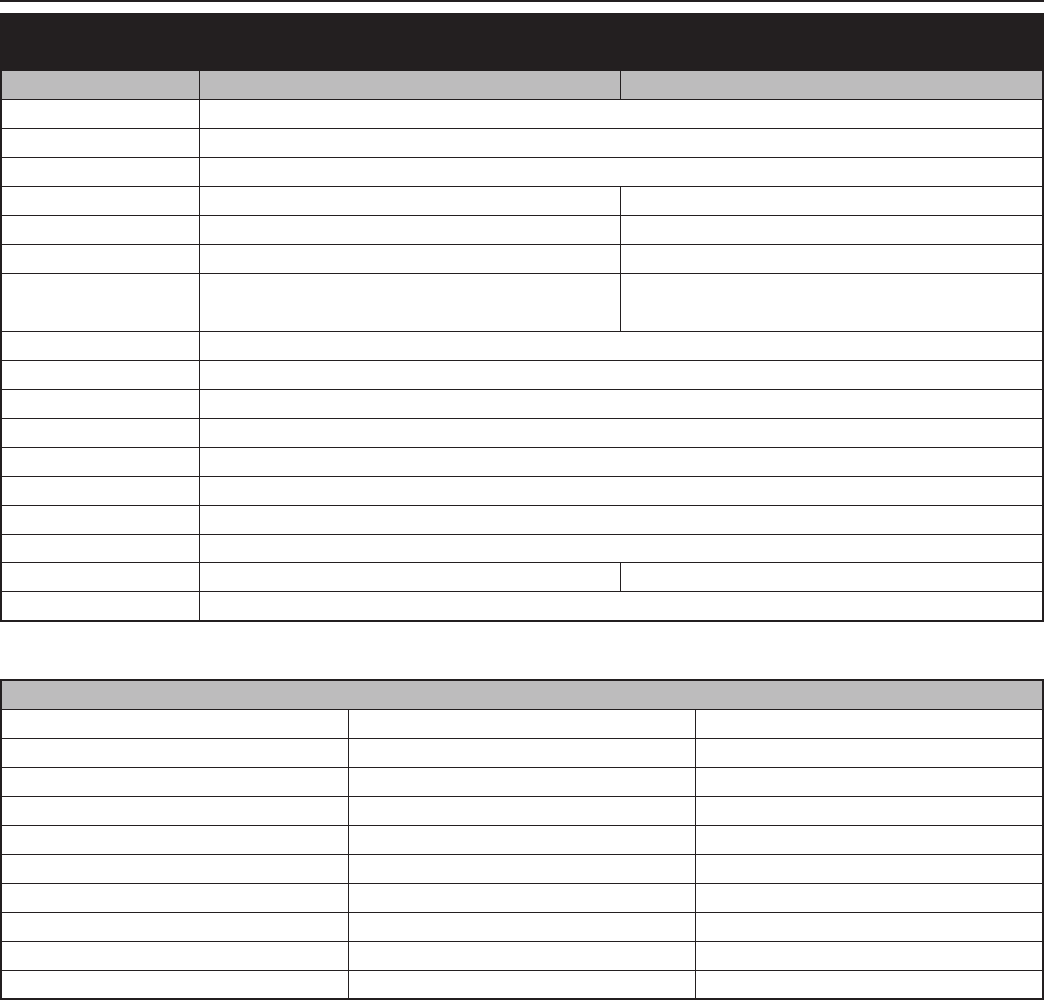
8-10E
TECHNICAL DATA – ENGINE 2005 AC
ENGINE 50 AC SENIOR ADVENTURE 50 AC MINI ADVENTURE
Design single cylinder 2-stroke engine, with reed valve inlet
Displacement 49.0 ccm
Bore/Stroke 39.5 / 40 mm
Fuel
Lead-free SUPER FUEL (ROZ 95), mixed with 2-stroke oil Lead-free SUPER FUEL (ROZ 95)
Lubrication mixture lubrication separate lubrication
Oil/gasoline ratio 1 : 40 –
2-stroke oil high-grade two-stroke oils for mixture lubrication high-grade two-stroke oils for separate lubrication
(Motorex Cross Power 2T) (Motorex Cross Power 2T)
Crankshaft bearing 2 grooved ball bearing
Connecting rod bearing
needle bearing
Piston pin bearing needle bearing
Piston rings 1 rectangular ring
Primary drive straight cut spur gears, 16 : 57 t
Transmission oil 0.15-0.2 liter gear oil Dexron II (Motorex ATF Super)
Spark plug NGK BR 8 ECM
Electrode gap 0.6 mm
Carburetor Dell’Orto PHVA 14 DS Dell’Orto PHVA 12 XS
Airfilter wet foam type air filter insert
BASIC CARBURETOR SETTING
MODEL 50 SENIOR ADVENTURE 50 MINI ADVENTURE
Type Dell’Orto PHVA 14 DS Dell’Orto PHVA 12 XS
Main jet 80 (70) 65 (70)
Needle jet 211 FA 211 FA
Idling jet 45 38
Jet needle A10 A10
Needle position from top 3. 4.
Air/Mixture reg. screw open 3.5 4
Slide 40 40
Starting jet 60 60
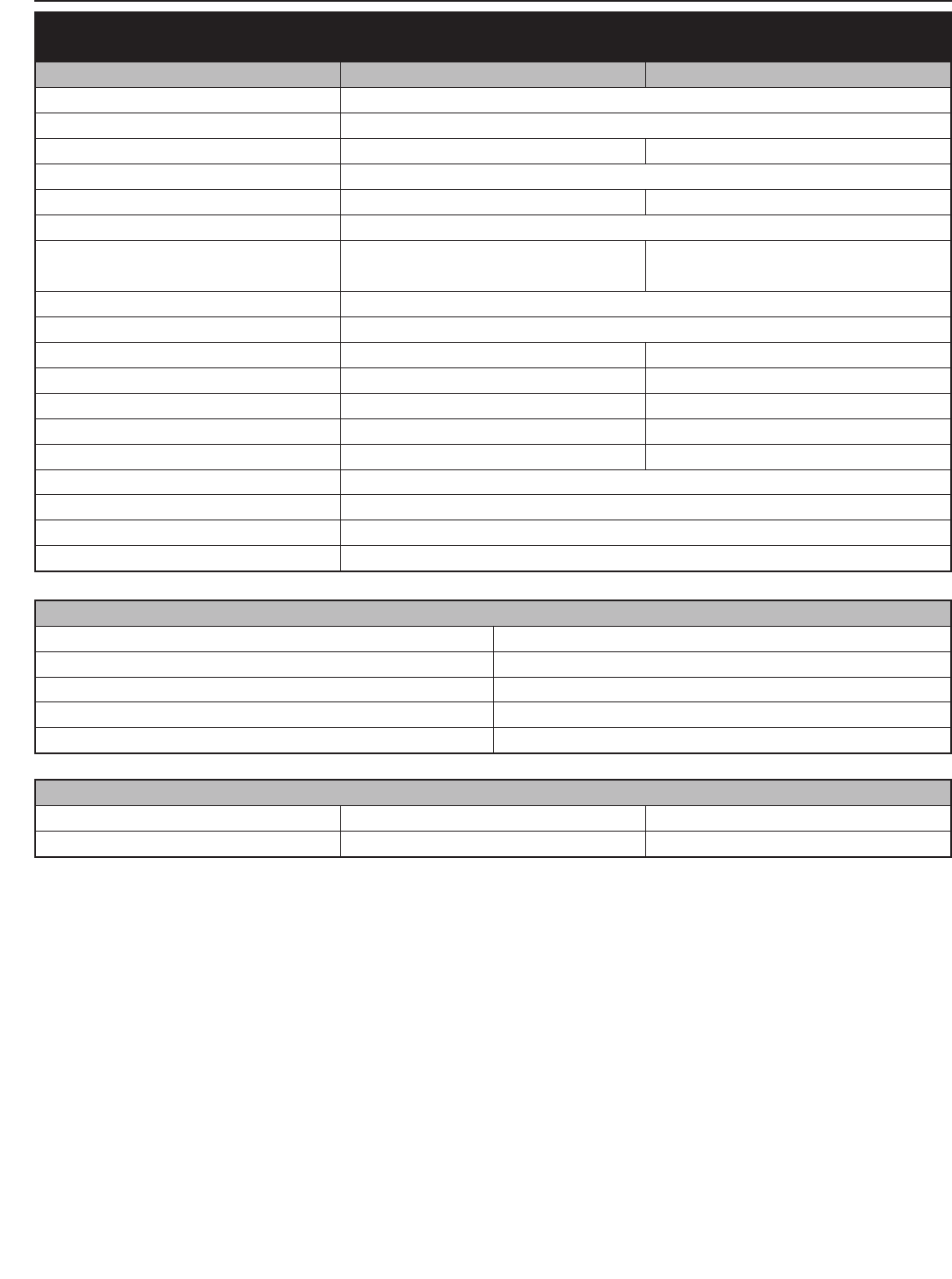
8-11E
Repair manual KTM MINI 50 air/liquid cooled Art.-Nr. 3.206.028 -E
TECHNICAL SPECIFICATIONS – CHASSIS 2005 AC
CHASSIS 50 SENIOR ADVENTURE 50 MINI ADVENTURE
Frame single downtube, split-cradle
Fork Marzocchi Ø = 32 mm (1,26 in)
Wheel travel front/rear 175/190 mm (6.9/7.5 in) 115/185 mm (4,5/7,3 in)
Rear suspension Central shock absorber Paioli
Front brake Disk brake Ø 160 mm (6.4 in) Drum brake Ø 90 mm (3,5 in)
Rear brake Drumbrake Ø 90 mm (3,5 in)
Tires front/rear
2.50x12“ Pirelli MT32A / 2.75x10“ MT320 2.50x10“ Pirelli MT32A / 2.75x10“ MT320
Tire pressure front/rear: 1.0 bar / 1.0 bar front/rear: 1.0 bar / 1.0 bar
Fuel tank capacity 2 liter (0.5 gallons)
Final drive ratio 11 : 48
Chain 1/2x3/16“ 104 rolls 1/2x3/16“ 96 rolls
Steering angle 66° 66°
Wheel base 1030 mm (40 in) 910 mm (35.8 in)
Seat height, unloaded
650 or 675 mm (25.6 or 26.6 in)
adjustable 530 or 550 mm (21 or 21.7 in) adjustable
Ground clearance 255 mm (10 in) 182mm (7.2 in)
Rider’s body height max. 130 cm (51 in)
Rider’s body weight max. 35 kg (78 lbs)
Recommended age of rider 4 - 6 years
Engine 50 AC
STANDARD-ADJUSTMENT – FORK
50 SENIOR / MINI ADVENTURE
Spring 2,0 N/mm
Preload 10 mm (0.4 in)
Fork oil SAE 7.5
Air chamber length 110 mm (4.3 in)
STANDARD ADJUSTMENT – SHOCK ABSORBER
50 SENIOR ADVENTURE 50 MINI ADVENTURE
Spring preload 12 mm (0.5 in) 8 mm (0.3. in)
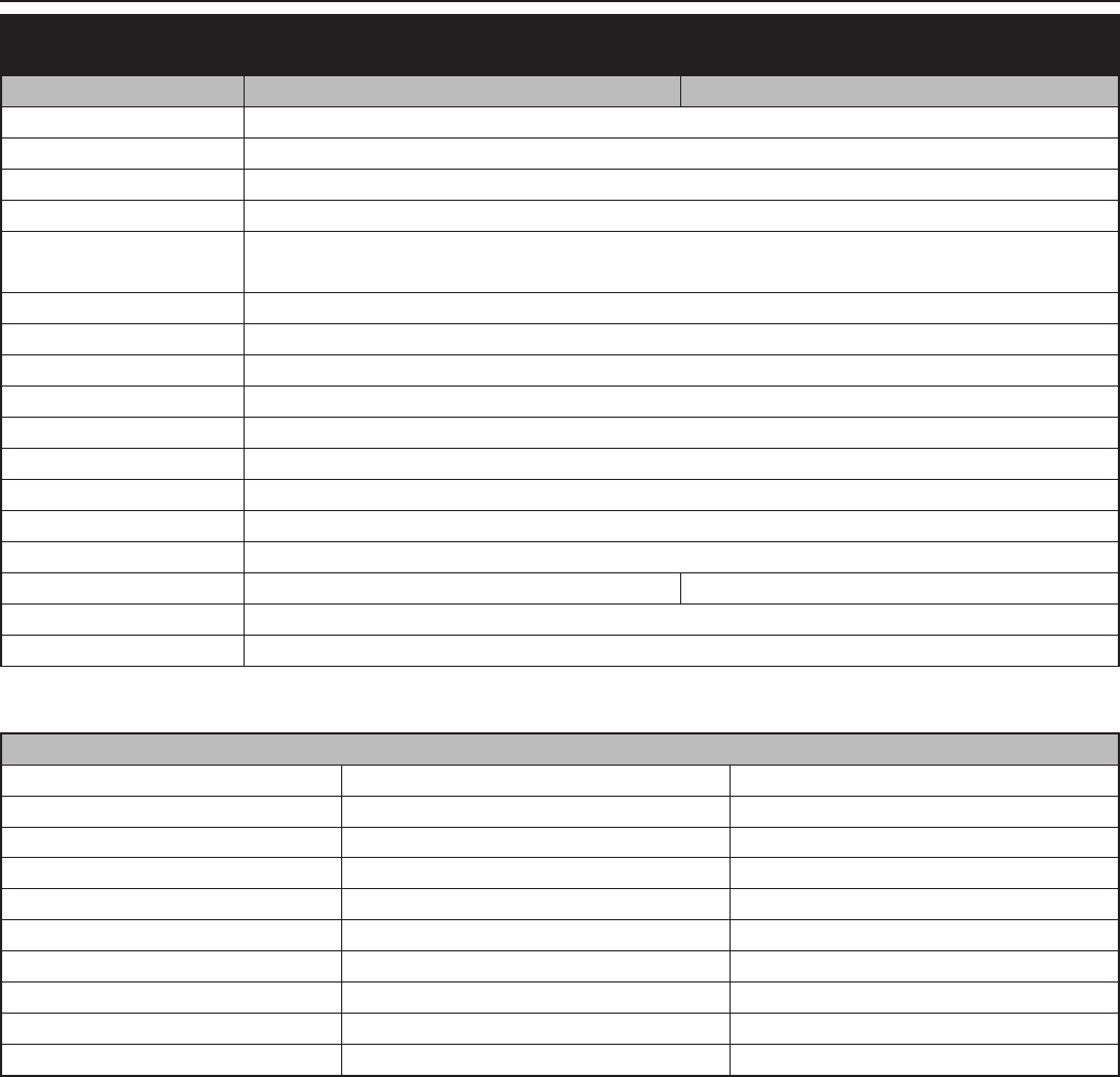
8-12E
TYP 50 SX PRO JUNIOR LC 50 SX PRO SENIOR LC
Design single cylinder 2-stroke engine, with reed valve inlet
Displacement 49.0 ccm
Bore/Stroke 39.5 / 40 mm
Fuel SUPER fuel, research octane no 95, mixed with 2-stroke oil
Oil/gasoline ratio 1 : 40 when using high grade 2-stroke oil (Motorex 2T Cross Power)
When in doubt, please contact your importer or use 1 : 33 mix ratio to be on the safe side
Lubrication mixture lubrication
Crankshaft bearing 2 grooved ball bearing
Connecting rod bearing needle bearing
Piston pin bearing needle bearing
Piston rings 1 rectangular ring
Primary drive straight cut spur gears, 16 : 57 Z
Transmission oil 0.15-0,2 liter automatic gear oil Dexron II (Motorex Topspeed 4T 15W50)
Spark plug NGK BR 8 ECM
Electrode gap 0.6 mm
Carburetor DellOrto PHVA 14 DS Dell’Orto PHBG 19 BS
Air filter wet foam type air filter insert
Cooling liquid 0.5 litres, 40% antifreeze, 60% water, at least -25 °C (-13 °F)
TECHNICAL DATA – ENGINE 2005 LC
BASIC CARBURETOR SETTING
Model 50 SX PRO JUNIOR LC 50 SX PRO SENIOR LC
Type Dell’Orto PHVA 14 DS Dell’Orto PHBG 19 BS
Main jet 80 85
Needle jet 211 FA 260 AU
Idling jet 45 48
Jet needle A10 W9
Needle position from top 3. 3.
Air/Mixture reg. screw open 3.5 3.0
Slide 40 60
Starting jet 60 60
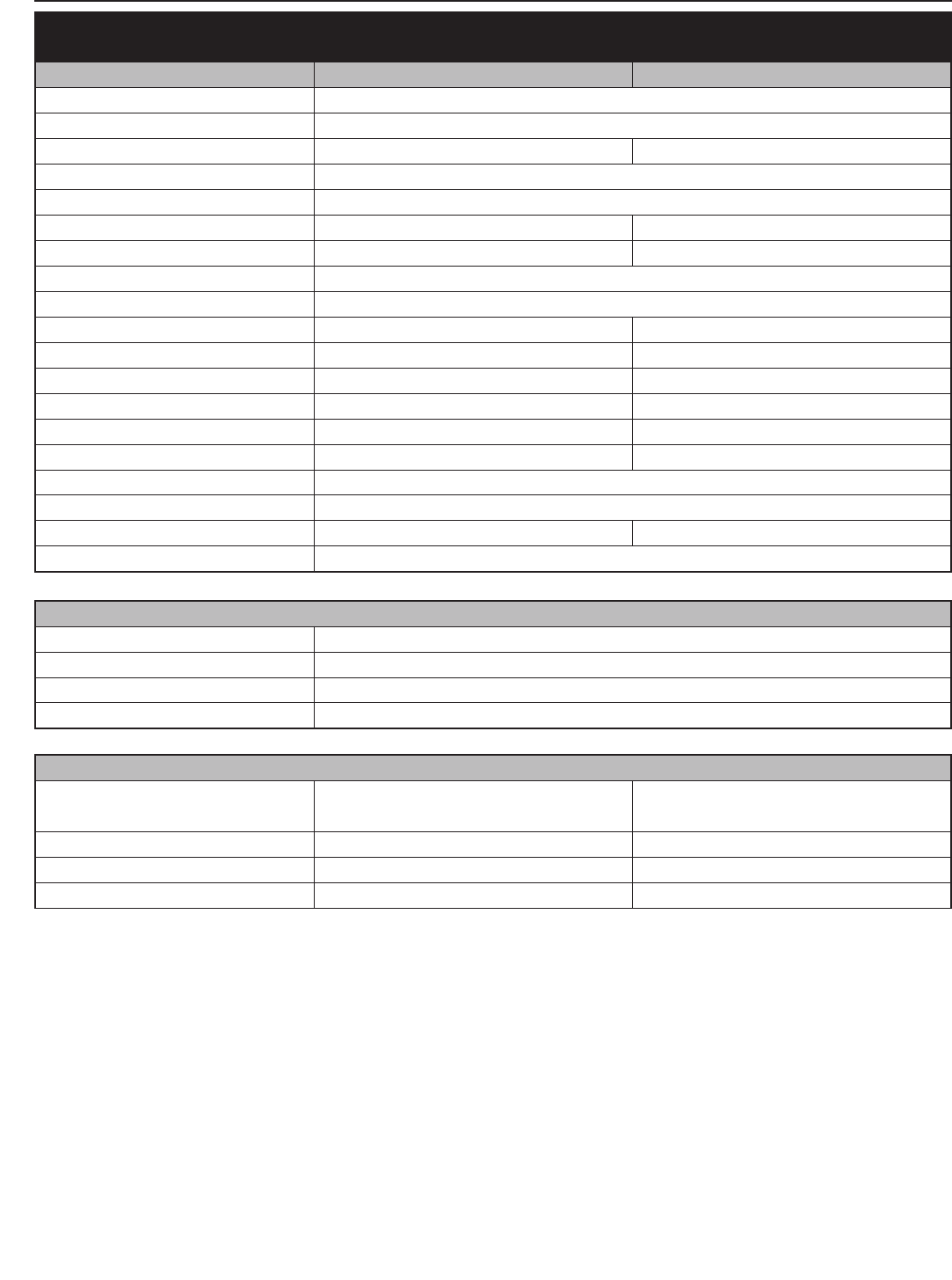
8-13E
Repair manual KTM MINI 50 air/liquid cooled Art.-Nr. 3.206.028 -E
50 SX PRO JUNIOR LC 50 SX PRO SENIOR LC
Frame single downtube, split-cradle
Fork Marzocchi Ø = 32 mm (1.26 in)
Wheel travel front/rear 140/205 mm (5.5/8 in) 185/185 mm (7.3/7.3 in)
Rear suspension Central shock absorber WP
Front brake Disk brake Ø 160 mm (6.4 in)
Rear brake Drum brake Ø 90 mm (3.5 in) Disk brake Ø 140 mm (5.5 in)
Tires front/rear 2.50x10” Pirelli MT32A / 2.75x10” MT320 2.50x12” Pirelli MT32A / 2.75x10” MT320
Tire pressure front/rear: 1.0 bar
Fuel tank capacity 1.8 Liters
Final drive ratio 11 : 48 10 : 44
Chain 1/2x3/16“ 96 rolls 1/2x3/16“ 102 rolls
Steering angle 66° 66°
Wheel base 910 mm (35.8 in) 1030 mm (40 in)
Seat height, unloaded 585 mm/610 mm (23/24 in) 650/675 mm (25.6/26.6 in)
Ground clearance 220 mm (8.6 in) 255 mm (10 in)
Rider’s body height max. 130 cm (51 in)
Rider’s body weight max. 35 kg (78 lbs)
Recommended age of rider 4-7 years 6-10 years
Engine 50 LC
TECHNICAL SPECIFICATIONS - CHASSIS 2005 LC
STANDARD-ADJUSTMENT – FORK
Spring 2.0 N/mm
Preload 10 mm (0.4 in)
Fork oil SAE 7.5
Air chamber length 110 mm (4.3 in)
STANDARD ADJUSTMENT – SHOCK ABSORBER
JUNIOR LC
WP 03189A01
SENIOR LC
WP 03189A02
Rebound adjuster 5 5
Spring 85 N/mm 45 N/mm
Spring preload 10 mm (0.39 in) 7 mm (0.28 in)

8-14E
TECHNICAL DATA – ENGINE 2006 AC
ENGINE 50 SENIOR ADVENTURE 50 MINI ADVENTURE
Design single cylinder 2-stroke engine, with reed valve inlet
Displacement 49.0 ccm
Bore/Stroke 39.5 / 40 mm
Fuel
Lead-free SUPER FUEL (ROZ 95), mixed with 2-stroke oil Lead-free SUPER FUEL (ROZ 95)
Lubrication mixture lubrication separate lubrication
Oil/gasoline ratio 1 : 60 –
2-stroke oil high-grade two-stroke oils for mixture lubrication high-grade two-stroke oils for separate lubrication
(Motorex Cross Power 2T) (Motorex Cross Power 2T)
Crankshaft bearing 2 grooved ball bearing
Connecting rod bearing
needle bearing
Piston pin bearing needle bearing
Piston rings 1 rectangular ring
Primary drive straight cut spur gears, 16 : 57 t
Transmission oil 0.15-0.2 liter gear oil Dexron II (Motorex ATF Super)
Spark plug NGK BR 8 ECM
Electrode gap 0.6 mm
Carburetor Dell’Orto PHVA 14 DS Dell’Orto PHVA 12 XS
Airfilter wet foam type air filter insert
BASIC CARBURETOR SETTING
MODEL 50 SENIOR ADVENTURE 50 MINI ADVENTURE
Type Dell’Orto PHVA 14 DS Dell’Orto PHVA 12 XS
Main jet 80 (70) 65 (70)
Needle jet 211 FA 211 FA
Idling jet 45 38
Jet needle A10 A10
Needle position from top 3. 4.
Air/Mixture reg. screw open 3.5 4
Slide 40 40
Starting jet 60 60
8-15E
Repair manual KTM MINI 50 air/liquid cooled Art.-Nr. 3.206.028 -E
TECHNICAL SPECIFICATIONS – CHASSIS 2006 AC
CHASSIS 50 SENIOR ADVENTURE 50 MINI ADVENTURE
Frame single downtube, split-cradle
Fork Marzocchi Ø = 32 mm (1,26 in)
Wheel travel front/rear 175/190 mm (6.9/7.5 in) 115/185 mm (4,5/7,3 in)
Rear suspension Central shock absorber Paioli
Front brake Disk brake Ø 160 mm (6.4 in) Drum brake Ø 90 mm (3,5 in)
Rear brake Drumbrake Ø 90 mm (3,5 in)
Tires front/rear
2.50x12“ Pirelli MT32A / 2.75x10“ MT320 2.50x10“ Pirelli MT32A / 2.75x10“ MT320
Tire pressure front/rear: 1.0 bar / 1.0 bar front/rear: 1.0 bar / 1.0 bar
Fuel tank capacity 2 liter (0.5 gallons)
Final drive ratio 11 : 48
Chain 1/2x3/16“ 104 rolls 1/2x3/16“ 96 rolls
Steering angle 66° 66°
Wheel base 1030 mm (40 in) 910 mm (35.8 in)
Seat height, unloaded
650 or 675 mm (25.6 or 26.6 in)
adjustable 530 or 550 mm (21 or 21.7 in) adjustable
Ground clearance 255 mm (10 in) 182mm (7.2 in)
Rider’s body height max. 130 cm (51 in)
Rider’s body weight max. 35 kg (78 lbs)
Recommended age of rider 4 - 6 years
Engine 50 AC
STANDARD-ADJUSTMENT – FORK
50 SENIOR / MINI ADVENTURE
Spring 2,0 N/mm
Preload 10 mm (0.4 in)
Fork oil SAE 7.5
Air chamber length 110 mm (4.3 in)
STANDARD ADJUSTMENT – SHOCK ABSORBER
50 SENIOR ADVENTURE 50 MINI ADVENTURE
Spring preload 12 mm (0.5 in) 8 mm (0.3. in)

8-16E
TYP 50 SX JUNIOR 50 SX, 50 SUPERMOTO
Design single cylinder 2-stroke engine, with reed valve inlet
Displacement 49.0 ccm
Bore/Stroke 39.5 / 40 mm
Fuel SUPER fuel, research octane no 95, mixed with 2-stroke oil
Oil/gasoline ratio 1 : 60 when using high grade 2-stroke oil (Motorex 2T Cross Power)
When in doubt, please contact your importer
Lubrication mixture lubrication
Crankshaft bearing 2 grooved ball bearing
Connecting rod bearing needle bearing
Piston pin bearing needle bearing
Piston rings 1 rectangular ring
Primary drive straight cut spur gears, 16 : 57 Z
Transmission oil 0.15-0,2 liter automatic gear oil Dexron II (Motorex Topspeed 4T 15W50)
Spark plug NGK BR 8 ECM
Electrode gap 0.6 mm
Carburetor DellOrto PHVA 14 DS Dell’Orto PHBG 19 BS
Air filter wet foam type air filter insert
Cooling liquid 0.5 litres, 50% antifreeze, 50% water, at least -25 °C (-13 °F)
TECHNICAL DATA – ENGINE 2006 LC
BASIC CARBURETOR SETTING
Model 50 SX JUNIOR 50 SX, 50 SUPERMOTO
Type Dell’Orto PHVA 14 DS Dell’Orto PHBG 19 BS
Main jet 80 85
Needle jet 211 FA 260 AU
Idling jet 45 48
Jet needle A10 W9
Needle position from top 3. 3.
Air/Mixture reg. screw open 3.5 3.0
Slide 40 60
Starting jet 60 60
8-17E
Repair manual KTM MINI 50 air/liquid cooled Art.-Nr. 3.206.028 -E
50 SX JUNIOR 50 SX 50 SUPERMOTO
Frame single downtube, split-cradle
Fork Marzocchi Ø = 32 mm (1.26 in)
Wheel travel front/rear 140/205 mm (5.5/8 in) 185/185 mm (7.3/7.3 in)
Rear suspension Central shock absorber WP
Front brake Disk brake Ø 160 mm (6.4 in)
Rear brake Drum brake Ø 90 mm (3.5 in) Disk brake Ø 140 mm (5.5 in)
Tires front 2.50x10” Pirelli MT32A 2.50x12” Pirelli MT32A 90/90-10 Pirelli SL26
Tires rear 2.75x10” MT320 90/90-10 Pirelli SL26
Tire pressure front/rear: 1.0 bar
Fuel tank capacity 1,8 Liter
Final drive ratio 11 : 48 10 : 44
Chain 1/2 x 3/16" 96 rolls 1/2 x 3/16" 102 rolls
Steering angle 66°
Wheel base 910 mm (35.8 in) 1030 mm (40 in)
Seat height unloaded 585 mm/610 mm (23/24 in) 650/675 mm (25.6/26.6 in)
Ground clearance unloaded 220 mm (8.6 in) 255 mm (10 in)
Rider’s body height max. 130 cm (51 in)
Rider’s body weight max. 35 kg (78 lbs)
Recommended age of rider 4 - 7 years 6 - 10 years
Engine 50 LC
TECHNICAL SPECIFICATIONS - CHASSIS 2006 LC
STANDARD-ADJUSTMENT – FORK
Spring 2,0 N/mm
Preload 10 mm (0.4 in)
Fork oil SAE 7,5
Air chamber length 110 mm (4.3 in)
STANDARD ADJUSTMENT – SHOCK ABSORBER
50 SX JUNIOR
WP 03189B01
50 SX, 50 SUPERMOTO
WP 03189B02
Rebound adjuster 5 5
Spring 85 N/mm 45 N/mm
Spring preload 10 mm (0.39 in) 7 mm (0.28 in)
8-18E
TOLERANCES AND FITTING CLEARANCES
Crankshaft run out of crank stud max. 0.050 mm
Crankshaft webs outer dimension 38 mm ±0.05 mm
Conrod bearing radial play max. 0.030 mm
Piston fitting clearance 0.055-0.065 mm (AC) / 0.045-0.055 mm (LC)
Piston ring end gap max. 0.20 mm
Clutch shoes outer diameter new 82.5 mm
Clutch drum diameter max. 84.4 mm (new 84.00 - 84.01 mm)
Clutch springs (AC) length min. 19.6 mm
TIGHTENING TORQUES - ENGINE
Hexagon nut primary gear M14x1.25 40 Nm
Hexagon nut ignition rotor M10x1.25 20 Nm
Hexagon nut of clutch hub M10x1.25 Loctite 243 + 35 Nm
HH bolts clutch shoes M6 Loctite 243 + 12 Nm
Cylinder head bolts M7 15 Nm
Cylinder base nuts M8 18 Nm
Allen head bolt-Stator M5 Loctite 243 + 8 Nm
Oil plug M16 5 Nm
Oil drain plug M10 15 Nm
Other bolts engine
M5 7 Nm
M6 10 Nm
M8 30 Nm
TIGHTENING TORQUES - CHASSIS
Hexagon nuts front/rear axle M12x1 40 Nm
Hexagon nut swing arm bolt
M10 45 Nm
M12 40 Nm
HH bolts of top triple clamp M8 20 Nm
HH bolts of bottom triple clamp
M6 10 Nm
M8 15 Nm
HH bolts handlebar clamp M8 20 Nm
Shock absorber top/bottom M10 45 Nm
Allen head bolt - Handlebar support M10 Loctite + 40 Nm
Front brake caliper M8 Loctite + 20 Nm
Front brake disk M6 Loctite + 10 Nm
Fixing screw brake pads M6 4 Nm
Spoke nipple
Mini Adventure M4 2,0 - 2,5 Nm
SX / Senior Adventure / Supermoto M4 2,5 - 3,0 Nm
Other bolts chassis
M5 6 Nm
M6 10 Nm
M8 25 Nm
M10 45 Nm
9-1E
Repair manual KTM MINI 50 air/liquid cooled Art.-Nr. 3.206.028-E
LUBRICATION AND MAINTENANCE SCHEDULE 50 AC/LC
MODEL 2002 . . . . . . . . . . . . . . . . . . . . . . . . . . . . . . . . . . . . . . . . . . . . . . . . .9-2
MODEL 2003-2005 . . . . . . . . . . . . . . . . . . . . . . . . . . . . . . . . . . . . . . . . . . . .9-4
MODEL 2006 . . . . . . . . . . . . . . . . . . . . . . . . . . . . . . . . . . . . . . . . . . . . . . . . .9-6
INDEX
LUBRICATION AND MAINTENANCE SCHEDULE 9
9-2E
MAINTENANCE WORK DONE BY KTM AUTHORISED WORKSHOPS IS NOT A SUBSTITUTE OF CARE AND CHECKS DONE BY THE RIDER!
PERIODIC MAINTENANCE 2002 50 MINIS
air/liquid cooled
A washed motorcycle can be checked more quickly which saves money!
Service Service
every every
5 hours 20 hours
ENGINE
Check engine for leaks
Change transmission oil
Check spark plug, change it if necessary, set electrode gap
Check the clutch engagement speed
CARBURETOR
Check carburetor for tight fit at intake flange
Check intake flange for cracks
Check idle setting when engine is warm
ADD-ON-PARTS
Check cooling system for leaks, antifreeze protection
Check exhaust system for leaks and suspension
Check actuating cables for damage, smooth operation, and kink-less
arrangement, adjust and lubricate
Clean air filter and air filter box
BRAKES
Check fluid level, lining thickness, brake discs
Check brake lines for damage
Check/adjust smooth operation, free travel of hand/footbrake levers
Check bolts of brake system for tight fit
CHASSIS
Check suspension strut and fork for leaks and proper function
Check swinging-fork pivot
Check/adjust steering-head bearing
Check all chassis bolts for tight fit (fork plates, axle nuts,
swinging-fork pivot, suspension strut)
WHEELS
Check spoke tension and rim joint
Check tire condition and inflation pressure
Check chain, chain wheels, chain wheel guides for wear, tight fit, and tension
Lubricate chain
Check wheel bearings for play
IMPORTANT RECOMMENDED MAINTENANCE PROCEDURES TO BE PERFORMED BASED ON A SEPARATE SUPPLEMENTARY ORDER
once
a year
Drain and clean the carburetor's float chamber
Perform complete fork maintenance
Clean and lubricate the swinging-arm bearing
Clean and lubricate the steering-head bearing and sealing elements
Change brake fluid
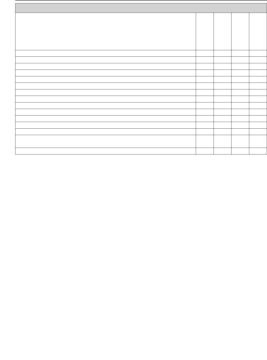
9-3E
Repair manual KTM MINI 50 air/liquid cooled Art.-Nr. 3.206.028 -E
VITAL CHECKS AND CARE PROCEDURES TO BE CONDUCTED BY THE OWNER OR THE MECHANIC
before each start
after every
cleaning
for cross country
use
once a year
Check transmission oil level
Check coolant level
Check brake fluid level
Check brake pads for wear
Check brake performance
Lubricate and adjust actuating cables and nipples
Remove and clean dust sleeves of telescopic fork in regular intervals
Clean and lubricate chain, check tension and readjust it if necessary
Clean air filter and filter box
Check tire inflation pressure and wear
Check fuel line for leaks
Drain and clean float chamber
Verify smooth operation of all controls
Treat exposed metal components (except for the brake and exhaust systems)
with wax-based anti-corrosion agents
Check all bolts, nuts, and hose clamps for their tight fit in regular intervals

9-4E
PERIODIC MAINTENANCE 2003-2005 50 MINIS
air/liquid cooled
A washed motorcycle can be checked more quickly which saves money!
Service Service
every every
5 hours 20 hours
ENGINE
Check engine for leaks
Change transmission oil
Check spark plug, change it if necessary, set electrode gap
Check the clutch engagement speed
CARBURETOR
Check carburetor for tight fit at intake flange
Check intake flange for cracks
Check idle setting when engine is warm
ADD-ON-PARTS
Check cooling system for leaks, antifreeze protection
Check exhaust system for leaks and suspension
Check actuating cables for damage, smooth operation, and kink-less
arrangement, adjust and lubricate
Clean air filter and air filter box
BRAKES
Check fluid level, lining thickness, brake discs
Check brake lines for damage
Check/adjust smooth operation, free travel of hand/footbrake levers
Check bolts of brake system for tight fit
CHASSIS
Check suspension strut and fork for leaks and proper function
Check swinging-fork pivot
Check/adjust steering-head bearing
Check all chassis bolts for tight fit (fork plates, axle nuts,
swinging-fork pivot, suspension strut)
WHEELS
Check spoke tension and rim joint
Check tire condition and inflation pressure
Check chain, chain wheels, chain wheel guides for wear, tight fit, and tension
Lubricate chain
Check wheel bearings for play
IMPORTANT RECOMMENDED MAINTENANCE PROCEDURES TO BE PERFORMED BASED ON A SEPARATE SUPPLEMENTARY ORDER
once
a year
Drain and clean the carburetor's float chamber
Perform complete fork maintenance
Clean and lubricate the swinging-arm bearing
Clean and lubricate the steering-head bearing and sealing elements
Change brake fluid
MAINTENANCE WORK DONE BY KTM AUTHORISED WORKSHOPS IS NOT A SUBSTITUTE OF CARE AND CHECKS DONE BY THE RIDER!
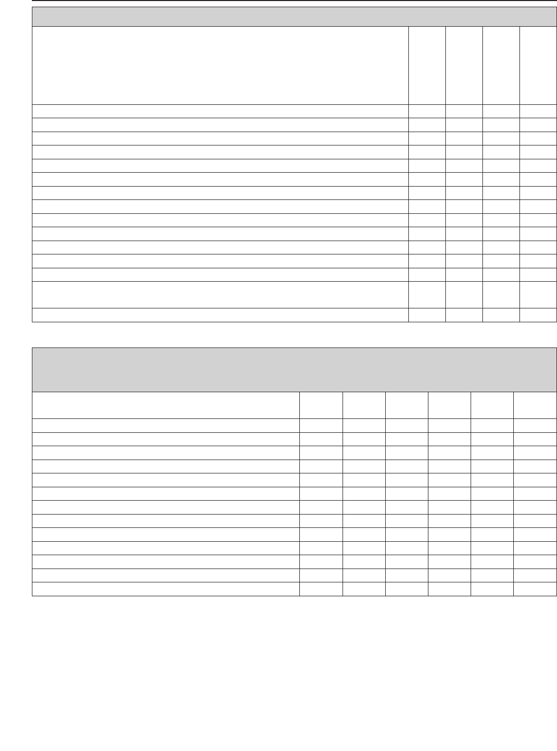
9-5E
Repair manual KTM MINI 50 air/liquid cooled Art.-Nr. 3.206.028 -E
NOTE: IF THE INSPECTION ESTABLISHES THAT PERMISSIBLE TOLERANCES ARE EXCEEDED, THE RESPECTIVE COMPONENTS MUST BE REPLACED.
VITAL CHECKS AND CARE PROCEDURES TO BE CONDUCTED BY THE OWNER OR THE MECHANIC
before each start
after every
cleaning
for cross country
use
once a year
Check transmission oil level
Check cooling liquid level
Check brake fluid level
Check brake pads for wear
Check brake performance
Lubricate and adjust actuating cables and nipples
Remove and clean dust sleeves of telescopic fork at regular intervals
Clean and lubricate chain, check tension and readjust it if necessary
Clean air filter and filter box
Check tire inflation pressure and wear
Check fuel line for leaks
Drain and clean float chamber
Verify smooth operation of all controls
Treat exposed metal components (except for the brake and exhaust systems)
with wax-based anti-corrosion agents
Check all bolts, nuts, and hose clamps for their tight fit at regular intervals
RECOMMENDED INSPECTION OF THE MINI AC/LC ENGINE BY YOUR KTM WORKSHOP
(ADDITIONAL ORDER FOR THE KTM WORKSHOP)
30 45 60 90 120 135
hours hours hours hours hours hours
Check the reed-type intake valve for wear
Check the clutch shoes for wear
Check the length of the clutch springs (AC)
Check the clutch drum for wear
Check the water pump shaft and bearings for wear
Check the water pump wheel for wear
Check the cylinder and piston for wear
Check the eccentricity of the crankshaft journal
Check the radial clearance of the conrod bearings
Check the radial clearance of the piston pin main bearing
Check the crankshaft main bearing for wear
Replace the crankshaft bearings and conrod bearings
Check the entire transmission including bearings for wear
9-6E
MAINTENANCE WORK DONE BY KTM AUTHORISED WORKSHOPS IS NOT A SUBSTITUTE OF CARE AND CHECKS DONE BY THE RIDER!
PERIODIC MAINTENANCE 2006 50 MINIS
air/liquid cooled
A washed motorcycle can be checked more quickly which saves money!
Service Service before
every every every
5 hours 20 hours race
ENGINE
Check engine for leaks
Change transmission oil
Check spark plug, change it if necessary, set electrode gap
Check the clutch engagement speed
CARBURETOR
Check carburetor for tight fit at intake flange
Check intake flange for cracks
Check idle setting when engine is warm
ADD-ON-PARTS
Check cooling system for leaks, antifreeze protection
Check exhaust system for leaks and correct fit
Check actuating cables for damage, smooth operation, and kink-less
arrangement, adjust and lubricate
Clean air filter and air filter box
BRAKES
Check fluid level, lining thickness, brake discs
Check brake lines and brake control cables for damage
Check/adjust function, smooth operation and free travel of
hand/footbrake levers
Check bolts of brake system for tight fit
CHASSIS
Check suspension strut and fork for leaks and proper function
Check swinging-fork pivot
Check/adjust steering-head bearing
Check all chassis bolts for tight fit (fork plates, axle nuts,
swinging-fork pivot, suspension strut)
WHEELS
Check spoke tension and rim joint
Check tire condition and inflation pressure
Check chain, chain wheels, chain wheel guides for wear, tight fit, and tension
Lubricate chain
Check wheel bearings for play
IMPORTANT RECOMMENDED MAINTENANCE PROCEDURES TO BE PERFORMED BASED ON A SEPARATE SUPPLEMENTARY ORDER
once
a year
Drain and clean the carburetor's float chamber
Perform complete fork maintenance
Clean and lubricate the swinging-arm bearing
Clean and lubricate the steering-head bearing and sealing elements
Change brake fluid
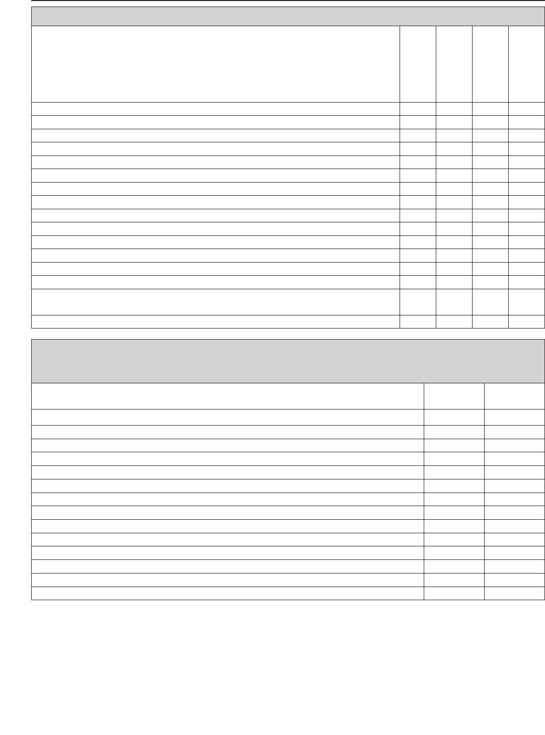
9-7E
Repair manual KTM MINI 50 air/liquid cooled Art.-Nr. 3.206.028 -E
NOTE: IF THE INSPECTION ESTABLISHES THAT PERMISSIBLE TOLERANCES ARE EXCEEDED, THE RESPECTIVE COMPONENTS MUST BE REPLACED.
VITAL CHECKS AND CARE PROCEDURES TO BE CONDUCTED BY THE OWNER OR THE MECHANIC
before each start
after every
cleaning
for cross country
use
once a year
Check transmission oil level
Check cooling liquid level
Check brake fluid level
Check brake pads for wear
Check brake performance
Lubricate and adjust actuating cables and nipples
Remove and clean dust sleeves of telescopic fork at regular intervals
Clean and lubricate chain, check tension and readjust it if necessary
Clean air filter and filter box
Check tire inflation pressure and wear
Check fuel line for leaks
Drain and clean float chamber
Check oil lines for cracks or kinks (for separate lubrication only)
Verify smooth operation of all controls
Treat exposed metal components (except for the brake and exhaust systems)
with wax-based anti-corrosion agents
Check all bolts, nuts, and hose clamps for their tight fit at regular intervals
RECOMMENDED INSPECTION OF THE MINI AC/LC ENGINE BY YOUR KTM WORKSHOP
(ADDITIONAL ORDER FOR THE KTM WORKSHOP)
after every after every
20 hours 40 hours
Check the reed-type intake valve for wear
Check the clutch shoes for wear
Check the length of the clutch springs (AC)
Check the clutch drum for wear
Check the water pump shaft and bearings for wear
Check the water pump wheel for wear
Check the cylinder and piston for wear
Check the oil pump (only separate lubrication)
Check the eccentricity of the crankshaft journal
Check the radial clearance of the conrod bearings
Check the radial clearance of the piston pin main bearing
Check the crankshaft main bearing for wear
Replace the crankshaft bearings and conrod bearings
Check the entire transmission including bearings for wear
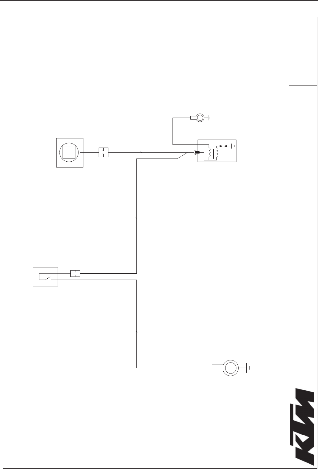
lioc noitingi
CL 05 roineS XS-.dA iniM
black
4002.20.02
G
kcalb
nottub pots
kcalb
rotareneg
10-2E
Cable colours:
black = black
