Kustom Signals DRU-III FIELD DISTURBANCE SENSOR User Manual DRU III Operator s Manual
Kustom Signals Inc FIELD DISTURBANCE SENSOR DRU III Operator s Manual
UserManual.wiki
>
Kustom Signals
>
DRU III User Manual
USERS MANUAL
Navigation menu
Upload a User Manual
Namespaces
Wiki Guide
HTML
PDF
Info
Views
User Manual
Discussion / Help
Navigation
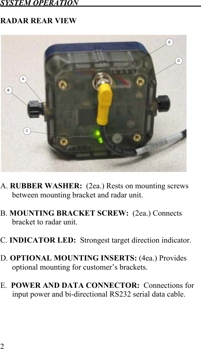
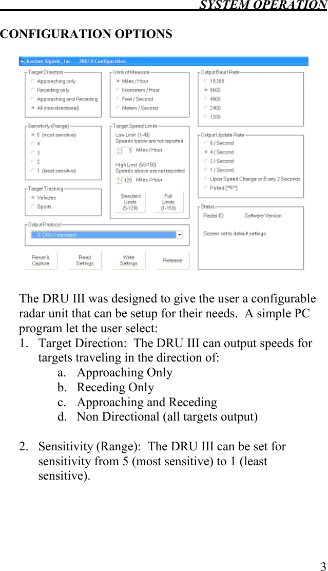

![SYSTEM OPERATION 5 8. Output Update Rate: The DRU III can be set to output packets of speed data at rates of (8 times per second, 4 times a second, 2 times a second, once a second, upon speed change, or when the user’s equipment polls for data) Note: If Output Update Rate is set to upon speed change, the DRU III outputs speeds immediately when the speeds changes by at least one unit or once every two seconds if the speed is not changing. If the DRU III is set to the Polled output, data is output when the DRU III receives characters [“*P”] or [“*P”0x0D]. 9. During the configuration session, the Status box will display information about the connected DRU III and the status of the configuration operations. To configure your DRU III unit, connect the DRU III data connector to the PC comm. port 1 and apply power to the DRU III. Click the Reset & Capture button to capture the DRU III for configuration. You can click the Read Settings button to populate the configuration screen with the current DRU III settings. Make any required changes in the configuration options and click the Write Settings to store these changes in the DRU III. When finished, click the Release button to return the DRU III to normal operation with the new configuration settings.](https://usermanual.wiki/Kustom-Signals/DRU-III/User-Guide-931691-Page-11.png)