Kustom Signals RPK FIELD DISTURBANCE SENSOR User Manual 006 0907 00 0
Kustom Signals Inc FIELD DISTURBANCE SENSOR 006 0907 00 0
USERS MANUAL

Raptor RP-1
Traffic Safety Radar
OPERATOR’S MANUAL
P/N 006-0907-00
Rev 0
1010 W CHESTNUT CHANUTE, KS 66720-0947
Copyright © 2008, Kustom Signals, Inc.
All Rights Reserved. Printed in U.S.A.
This publication may not be reproduced, stored in a retrieval
system, or transmitted in whole or in part in any form or by any
means electronic, mechanical, photocopying, recording, or
otherwise without prior written permission of Kustom Signals,
Inc., 9325 Pflumm Road, Lenexa, KS 66215-3347
Customer Service 1-800-835-0156 (620-431-2700)
Sales Department 1-800-4-KUSTOM (913-492-1400)

TABLE OF CONTENTS
SECTION PAGE
1. INTRODUCTION...........................................................1.1
2. SPECIFICATIONS
2.0 General.......................................................................2.1
2.1 Operational.................................................................2.4
3. INSPECTION AND INSTALLATION
3.0 Initial Inspection ........................................................3.1
3.1 Material Supplied.......................................................3.1
3.2 VSS Pulse Cable Installation .....................................3.2
3.3 Radar Installation.......................................................3.3
4. UNIT DESCRIPTION
4.0 Display Panel View....................................................4.1
4.1 Target Signal Tracking Bars ......................................4.3
4.2 Remote Control..........................................................4.4
4.3 Processing Unit Rear Panel........................................4.6
5. GENERAL THEORY of OPERATION
5.0 Block Diagram...........................................................5.1
5.1 General.......................................................................5.2
5.2 Microwave RF Emissions..........................................5.5
6. TESTING PROCEDURES
6.0 General.......................................................................6.1
6.1 Power-On ...................................................................6.1
6.2 Automatic Self Test ...................................................6.2
6.3 Manual Test ...............................................................6.2

TABLE OF CONTENTS
SECTION PAGE
6.4 Tuning Fork Testing ..................................................6.3
6.5 Speedometer Verification ..........................................6.8
6.6 Minimum Patrol Speed Set......................................6.10
6.7 Moving Mode Test...................................................6.10
7. OPERATION
7.0 Operating Modes........................................................7.1
7.1 Operational Setup.......................................................7.2
7.2 Stationary Operation ..................................................7.4
7.3 Moving Mode—Opposite Direction..........................7.9
7.4 Moving Mode—Same Direction..............................7.12
7.6 Speedometer Pulse Operation...................................7.13
7.7 Menu Screen Modes .................................................7.14
7.7.1 Main Menu Screen...........................................7.16
7.7.2 Operations Menu Screen..................................7.17
7.7.3 Display Menu Screen.......................................7.18
7.7.4 Advanced Menu Screen ...................................7.19
7.7.5 VSS Setup Menu Screen..................................7.20
7.7.6 Options Menu Screen.......................................7.21
7.7.7 Time / Date Setup Menu Screen ......................7.22
7.7.8 System Information Menu Screen ...................7.23
7.7.9 Diagnostics Menu Screen ................................7.24
8. INFLUENCES AND INTERFERENCE
8.0 Natural Influences......................................................8.1
8.1 Man-Made Influences ................................................8.2
8.2 Groundspeed ..............................................................8.4
9. CARE OF THE Raptor RP-1
9.0 Routine Care ..............................................................9.1
9.1 Equipment Repair/Return ..........................................9.2
9.2 Battery Disposal.........................................................9.3

TABLE OF CONTENTS
SECTION PAGE
10. CASE LAW ...................................................................10.1
11. FCC INFORMATION..................................................11.1
12. TROUBLESHOOTING ...............................................12.1
13. DIRECTIONAL OPERATIONAL SUPPLEMENT.13.1
13.0 Directional Operation.............................................13.1
13.1 Stationary Road Graphic........................................13.2
13.2 Moving Mode Road Graphic .................................13.2
13.3 Test Mode ..............................................................13.3
13.4 Stationary Operation ..............................................13.4
13.5 Moving Mode Operation........................................13.7
13.6 Fastest Locking ....................................................13.10
14. WARRANTY.................................................................14.1

SECTION 1--INTRODUCTION
1.1
1. INTRODUCTION
The Kustom Signals Raptor RP-1 directional radar system
comes from a long-standing commitment to the law
enforcement community to provide quality, state-of-the-art
speed measuring equipment. The Raptor RP-1 offers a
wide range of features on this moving/stationary K or Ka-
Band radar system, yet allows easy operation and simple
one-button mode changes.
Raptor RP-1 units have the newest directional features;
D
ual
C
hannel
M
icrowave antennas and Directional
D
igital
S
ignal
P
rocessing (DSP). This allows Kustom Signals to
add features such as same direction with automatic add or
subtract difference speed, fastest vehicle detection in all
modes, TruTrak with
A
utomatic
M
ode
S
witching (AMS),
S
mart
P
atrol
S
earch (SPS) and stationary modes that allow
the operator to select approaching only, receding only, or
all targets identification. With these features, the officer
can better identify the offending vehicle and eliminate
much of the confusion of high traffic environments.
All these features and performance standards are packed
into this small, lightweight unit, providing the most
flexibility for the operator.
The Raptor RP-1 K-Band antenna sets a new standard for
low power / low current operation. This will be
appreciated as low draw on the already heavily taxed patrol
vehicle’s power source. The higher powered Ka-Band
antenna offers higher detection range.

SECTION 2--SPECIFICATIONS
2.1
2. SPECIFICATIONS
2.0 GENERAL
Type: Two-piece, Directional Moving /
Stationary, Doppler radar system.
Frequency: K-Band 24.125 GHz +100 MHz
System Accuracy: Stationary +1 mph (+1km/h)
Moving +1/-2 mph (+1/-2 km/h)
Corded: 10.0 to 16.5 VDC, 340 mA
max.
Operating Voltage:
The Raptor RP-1 will operate
normally and not display a low
voltage alert to at least 10.0 VDC.
Typically it will continue to operate
even when the external battery
voltage drops substantially below the
specified 10.0 VDC.
Low Voltage
Threshold:
Corded: Typically 8.5 VDC

SECTION 2--SPECIFICATIONS
2.2
Nominal Power
Requirements:
Voltage (VDC) Current (mA)
No target present:
Backlight = Off
Backlight = On
13.6
160
13.6 230
With target present:
Audio = Max
Backlight = Off
13.6 190
With target present:
Audio = Max
Backlight = On
13.6 260
Standby (HOLD):
Backlight = Off 13.6
100
Over Current
Protection: Automatic resetting protection
devices on power lines of processing
unit, display, antenna, and wired
remote.
Electronic
Components: 100% solid state; integrated circuits,
Digital Signal Processor, and micro-
controller.
Operating
Temperature: -22
°
F to +140
°
F (-30
°
C to +60
°
C)
90% relative humidity at 37
°
C, non-
condensing.

SECTION 2--SPECIFICATIONS
2.3
Dimensions:
Display Unit:
Height: 2.6” (6.60 cm)
Width: 4.1” (10.41 cm)
Depth: 1.5” (3.81 cm)
Weight: 0.30 lb. (0.14 kg)
Processing Unit:
Height: 1.2” (3.05 cm)
Width: 3.9” (9.91 cm)
Depth: 2.35” (5.97 cm)
Weight: 0.35 lb (0.16 kg)
Antenna Unit (K-Band):
Height: 3.1” (7.87 cm)
Width: 3.1” (7.87 cm)
Depth: 1.5” (3.81 cm)
Weight: 0.45 lb (0.21 kg)

SECTION 2--SPECIFICATIONS
2.4
2.1 OPERATIONAL
Speed Processor: Digital Signal Processor (DSP)
performs all signal analysis and
speed calculations.
Manual Test: All display pixels checked; checks
internal calibration and performs a
cross check of quartz crystals for
timing accuracy.
Automatic self-test: Comparison of quartz crystals done
periodically (5 minutes maximum),
upon every mode change and at the
time of lock. “XTAL ERROR”
displayed if an error is found.
Lock Time: Instantaneous.
Patrol window area: Displays Doppler patrol speed.
Target window area: Displays truncated target speed.
Lock/Fast window: Displays locked target speed or
fastest vehicle in Fast mode.
Display Type: Transflective Graphical Liquid
Crystal Display (LCD).
Back Lighting: White Light Emitting Diode (LED).

SECTION 2--SPECIFICATIONS
2.5
Speed Range: Meets IACP/NHTSA specifications
for target sensitivity.
Stationary: 10 dB from 35 to 90 mph
(56 to 144 km/h); 5 dB from 60 to 90
mph (96 to 144 km/h).
Moving (Opposite Dir.): 10 dB for
targets from 40 to 90 mph (64 to 144
km/h); 5 dB from 60 to 90 mph (96
to 144 km/h).
Moving (Same Dir.): 10 dB for
targets from 5 to 25 mph (8 to 40
km/h).
Stationary: Spec: 10 to 205 mph (16 to 330
km/h).
Typical: 6 to 208 mph (9 to 334
km/h).
Moving:
Patrol: Spec: 10 to 100 mph (16 to 160
km/h)
Typical: 6 to 120 mph (9 to 193
km/h).

SECTION 2--SPECIFICATIONS
2.6
Target:
Opposite Dir.: Target minimum (Patrol < 40 mph):
Spec: 10 mph (16 km/h)
Typical: 9mph (14 km/h)
Target minimum (Patrol > 40 mph):
Spec: 20 mph (32 km/h)
Target maximum:
(Combined patrol and target speeds):
Spec: 205 mph (330 km/h)
Typical: 208 mph (334 km/h).
Same Dir.: Minimum difference speed:
Spec: 5 mph (8 km/h)
Typical: 3 mph (5 km/h).
Maximum difference: 0.65 x Patrol
Speed.

SECTION 2--SPECIFICATIONS
2.7
Indicators:
Stationary: Stationary operation displays “STA”.
Stationary modes display “ALL”,
“APR ONLY”, or “REC ONLY”.
Moving: Moving operation “PATROL” above
the patrol speed area.
Low Voltage: Displays “LOW VOLTAGE” in the
message area when internal voltage
falls below approximately 8.5 VDC.
The transmitter is disabled, but
locked speeds will remain.
Radio Frequency Displays “RFI ERROR” in the
Interference: message area during strong radio
frequency interference. Active speed
displays are blanked during this
condition. Locked speeds will
remain.
Timing Error: Displays “XTAL ERROR” in the
message area when an internal error
in the operating system is detected.
Active speed displays will blank.
Locked speeds will remain.
Transmitter Hold: Displays “HOLD” above the active
target speed area and in the message
area when the system is not
transmitting. (Controlled by the
front panel or remote control).

SECTION 2--SPECIFICATIONS
2.8
Lock: “LOCK” displayed and flashing
above the FAST/LOCK speed area
indicating locked target speed.
Fastest: “FAST” displayed above the
FAST/Lock speed area when fastest
mode (stationary or moving) is
enabled.
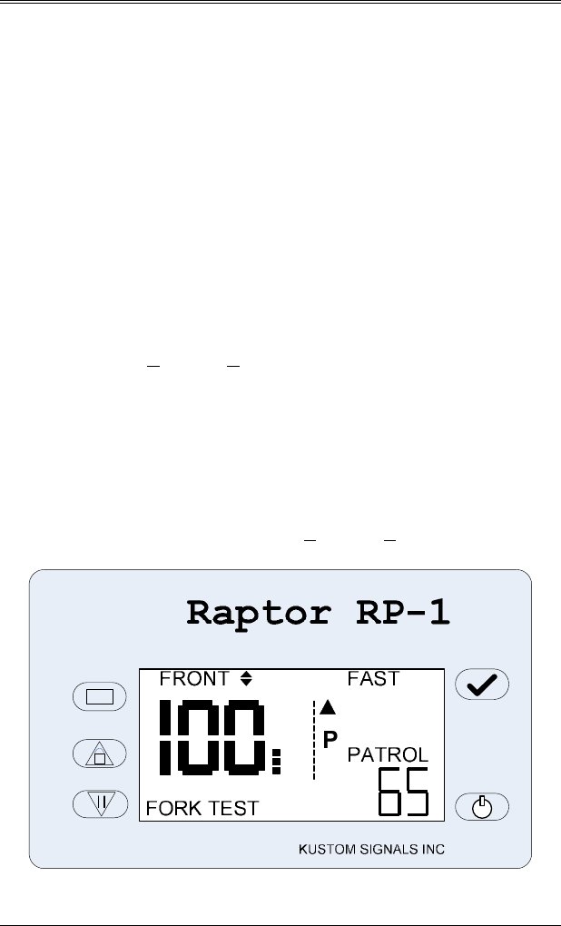
Fork Test: Displays “FORK TEST” in the
message area when the unit is in
tuning fork test mode.
Km/h: Displays “Km/h” above the road
graphic area when the option for
units is set to km/h.
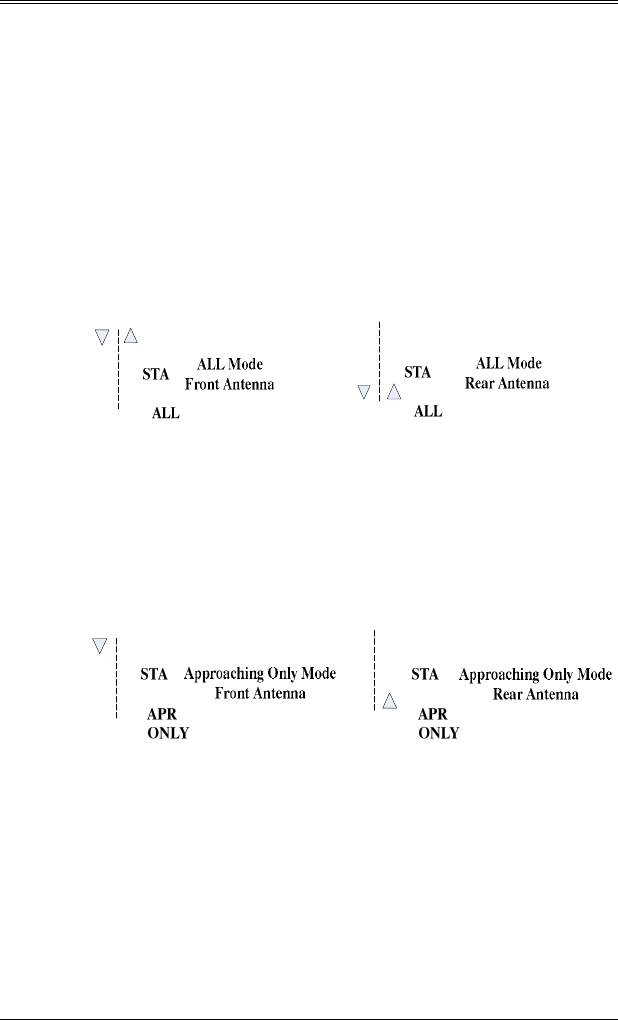
Road Graphic: These indicators show the mode of
operation of the active antenna. In
HOLD the mode of operation of both
antennas are shown.
Target Direction: There indicators above both target
speed areas to indicate the direction
of travel of the targets.
Microwave Freq: 24.125 GHz.
Beam Width: 12
°
+1
°
.
(Horizontal)
Polarization: Linear.
Power Density: Less than 1 mW/cm
2
at aperture.
Source Power: 8 mW max.

SECTION 3—INSPECTION AND INSTALLATION
3.1
3. INSPECTION AND INSTALLATION
3.0 INITIAL INSPECTION
Before installing your Raptor RP-1, please take a moment
to carefully inspect the shipping carton for damage.
Contact the shipping carrier at once if you notice any
damage.
Remove the unit from the shipping carton and check the
packing list against your original purchase order. If the
shipment is incomplete or parts are missing, please contact
Kustom Signals Customer Service Department at 1-800-
835-0156, or (620) 431-2700.
3.1 MATERIALS SUPPLIED
The following equipment is normally included:
Processing/Display Unit
Antenna Unit
Wired Remote Control
Antenna Cable
Antenna Mount
Processing/Display Mount
Speedometer Pulse Interface Cable
Tuning Forks (35 & 65 mph)
Operator’s Manual - CD
OPTIONAL EQUIPMENT
2
nd
Antenna
2
nd
Antenna Cable
IR Remote Control
Processing/Display Separation Cable
Video Interface Cable
Heavy Duty Carrying Case

SECTION 3—INSPECTION AND INSTALLATION
3.2
3.2 VSS PULSE CABLE INSTALLATION
Installing the provided cable to the vehicle’s speed sensor
(VSS) provides a signal to the Raptor RP-1 for Kustom
Signals’ patented Tru-Trak assisted patrol speed search
feature. This feature virtually eliminates the problems of
patrol shadowing and patrol combining. This signal also
allows the unit to automatically switch between moving
and stationary modes as the vehicle’s movement is sensed.
1. The VSS pulse cable has a connector at one end, which
plugs into the back panel of the processing unit.
2. The red wire (inner conductor) of the cable will be
connected to the patrol vehicle’s electrical speedometer
input cable using the splice connector provided. Due to
the vast amount of models, makes and years of
vehicles, we have moved access to specific vehicle
diagrams online where information can be better
maintained and distributed.
Installation details can be accessed at:
http://www.kustomsignals.com
(select: radar fixed mount)
If your vehicle year, make and/or model is not listed, please
contact Kustom’s Customer Service Department at (800) 835-
0156. If you are outside the US and Canada, please call (620)
431-2700.
NOTE: Only the inner conductor of the speedometer pulse
cable is used. The outer shield is not connected.
3. The speedometer interface will be set up later, in Sec.
6.5.

SECTION 3—INSPECTION AND INSTALLATION
3.3
3.3 RADAR INSTALLATION
3.3.1 INDICATOR UNIT
CAUTION: Equipment mounted in 1994 and later
series police vehicles may interfere with the operation of
passenger side airbags. Please refer to the vehicle
manufacturer or your Kustom Signals District Manager for
additional information on safe mounting areas within the
vehicle.
1. The indicator unit consists of two components: the front
display panel, which contains the unit's LCD display
and control switches, and the processing unit, which
contains the main signal processing board. These two
components can be mounted in the vehicle as one piece
or they can be separated and mounted in different
locations.
The Raptor RP-1's display panel can be located
overhead, on the dashboard or on the radio rack. The
processing unit can be located under the dash, in the
glove box or under the front seat.
2. Locate the provided Display/Processing mount.
Position the display for best viewing position in the
patrol vehicle and secure the mount.
3.
If the processing section is separated from the display,
consider mounting it in a convenient yet protected
location, i.e. under the dash, in the glove box or under
the front seat. The interconnect cable for the two
components attaches to the rear of the display panel and
front panel of the processing unit.
SECTION 3—INSPECTION AND INSTALLATION
3.4
3.3.2 FRONT ANTENNA MOUNTING
Provided with the Raptor RP-1 is a windshield-type
mount for the antenna. Contact your District Manager or
Kustom Signals' Customer Service department for other
optional antenna mounts.
1. Attach the antenna to the mount.
2. Use the antenna cable to connect the antenna to the
Raptor RP-1's processing unit, front antenna port.
Refer to Sec. 4.1 for antenna port location.
3. Connect the Raptor RP-1's power plug to the proper
power source.
4. Momentarily depress the POWER switch on the front
panel of the Raptor RP-1 (refer to Sec. 4.0 for location
and function of front panel switches). It will process
through the power-up sequence and internal tests as
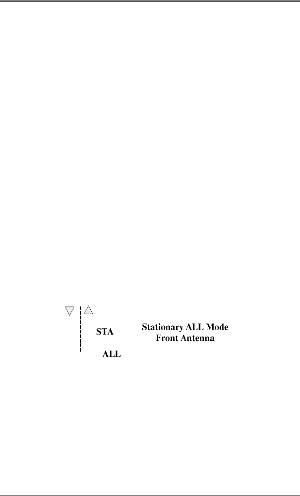
described later in Sec. 6. Select Stationary mode ALL
by depressing the remote MODE switch until “STA”
and “ALL” are displayed in the Patrol area. Both
directional indicators (front antenna) will be lit.

SECTION 3—INSPECTION AND INSTALLATION
3.5
5. Place the Raptor RP-1 in the unsquelched (audio on)
mode. Set the audio level to a point the noise from the
antenna can be heard.
a. Press the Menu switch to go to the main menu
screen.
b. Use the Down switch to highlight the AUDIO option.
c. Press the Enter switch to change audio settings.
(Audio level setting will be blinking)
d. Use the Test(√) switch to toggle the squelch /
unsquelch setting.
e. Press Enter to save the setting and return to the
Exit line.
f. Press Enter again to return to the normal operating
screen.
6. Start the patrol vehicle and position the A/C - heater
fan to a mid-range speed. Move the antenna/mount to
different positions on the windshield while listening to
the audio. If there is fan interference, the audio will
have a raspy sound instead of just noise. Position the
antenna to minimize the amount of fan interference.
1. Aim of the antenna:
Stationary: Maximum performance of the system will
be achieved when the antenna is aimed
directly toward the vehicles being
monitored.
Moving: Aim the antenna parallel to the ground
and straight down the roadway.
NOTE: The polarization of the Raptor RP-1 K-Band
antenna is linear. For best results the antenna
must be mounted with the aim site on the housing
at the top or bottom, not to the side.

SECTION 3—INSPECTION AND INSTALLATION
3.6
3.3.3 REAR ANTENNA MOUNTING
1. Place the antenna on the rear antenna mount.
2. Follow the procedure for determining any fan
interference per Sec. 3.3.2, steps 4-6. Set the Raptor
RP-1 for stationary ALL mode, rear antenna.
3. After the optimum position has been located (per Sec.
3.2.3 Step 6), secure the mount.
4. Position the antenna cable behind the rear seat and
under the rear floorboard, then route up to the
processing unit and connect. This method of
mounting will minimize the antenna from moving
around in the vehicle should it break loose in an
accident. It should also prevent anyone from using
the cable as a weapon against the officer.
5. Position the antenna parallel to the ground and
straight down the roadway.
NOTE: The polarization of the Raptor RP-1 K-Band
antenna is linear. For best results the antenna
must mounted with the aim site on the housing at
the top or bottom, not to the side.
SECTION 4—UNIT DESCRIPTION
4.1
4. UNIT DESCRIPTION
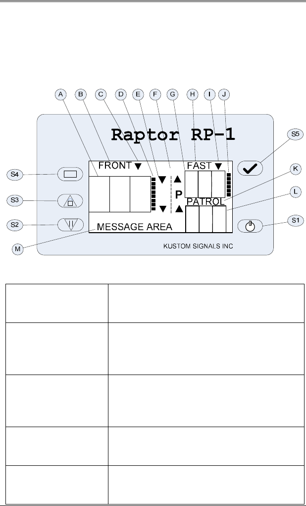
4.0 DISPLAY PANEL VIEW
MAIN ENFORCEMENT STATE
S1. Power Switch Control for power on / off and for
toggling backlight on / off.
S2. Hold (↓)
Switch
Toggles the active antenna microwave
transmitter on and off. In setup menu
screens this is the down control.
S3. Lock/Release
(↑) Switch
Alternately Locks and Releases the
target and patrol speeds. In setup
menu screens this is the up control.
S4. Enter Switch Places the unit in the menu screen.
Used to enter a selection.
S5. Test Switch Initiates the display, internal self-test
and tuning fork test mode.

SECTION 4—UNIT DESCRIPTION
4.2
A. Primary Target
Speed Area
Displays target vehicle speeds in
stationary and moving modes.
B. Active Antenna Indicates FRONT or REAR for the
current active antenna. HOLD if no
antenna active.
C. Directional
Indicator
Indicates the direction of travel of the
target displayed in the Target Speed
Area.
D. Target Signal
Tracking Bar
Displays the signal strength history of
the target displayed in the Target
Speed Area.
E. Road Graphic Indicates the mode of operation for
each antenna.
F. Unit of Measure
Indicator
Indicates Km/h when the speed
readings are in kilometers per hour.
This area is blank if speeds are in
MPH.
G. Fast / Lock
Speed Area
Displays Fastest or Locked target
speed.
H. Fast / Lock
Label
Displays FAST when the Fast/Lock
area is displaying a Fastest speed.
Displays LOCK when the Fast/Lock
area is displaying a Locked speed.
I. Directional
Indicator
Indicates the direction of travel of the
target displayed in the Fast/Lock
Speed Area.

SECTION 4—UNIT DESCRIPTION
4.3
J. Target Signal
Tracking Bar
Displays the signal strength history of
the target displayed in the Lock/Fast
Speed Area.
K. Patrol Area
Label
Displays PATROL in moving mode or
STA in stationary mode.
L. Patrol Speed
Area
Displays the vehicle’s Patrol Speed in
moving mode or in stationary mode
displays ALL, APR ONLY, or REC
ONLY.
M. Message Area Displays relevant status and error
messages in this area
4.1 TARGET SIGNAL TRACKING BARS
The Target Signal Tracking Bars are a new feature from
Kustom Signals. The level on the bar shows the user the
signal strength duration of the current target. This is not
the same as the instantaneous signals strength. The signal
strength duration shows the accumulated signal to noise
ratio of the current target. A strong target will cause the
duration level to rise quickly, whereas a weak target will
cause the duration level to rise more slowly.
SECTION 4—UNIT DESCRIPTION
4.4
4.2 REMOTE CONTROL
Wired Remote
SIGNALS, INC.
Raptor RP-1
Raptor RP-1
Wireless Remote
, .SIGNALS INC
A
B
C
G
D
E
F
H
A
B
C
D
E
F
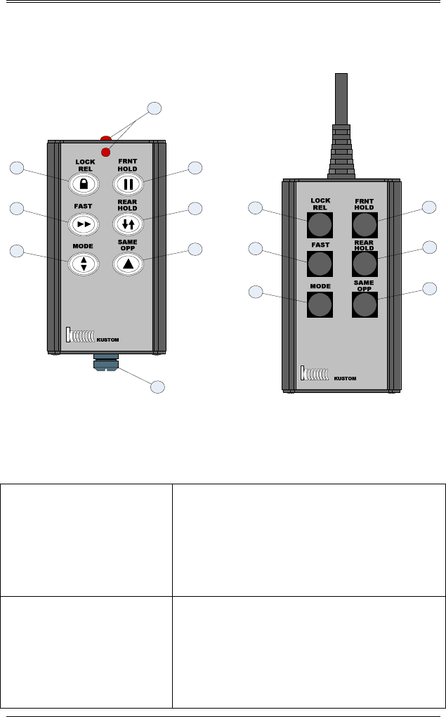
Certain functions of the Raptor RP-1 can be controlled with a
wired or optional wireless/infrared (IR) remote.
A. FRONT HOLD This switch is used to turn the front
antenna microwave transmitter on
and off. If the rear antenna is active,
it will be placed in Hold and the front
antenna will become active.
B. REAR HOLD This switch is used to turn the rear
antenna microwave transmitter on
and off. If the front antenna is active,
it will be placed in Hold and the rear
antenna will become active.

SECTION 4—UNIT DESCRIPTION
4.5
C. SAME/
OPPOSITE
In moving mode this switch toggles
between the same direction or
opposite direction mode.
In stationary selective modes, this
switch toggles approaching only and
receding only directions.
This changes the modes of the active
antenna only. The inactive antenna
will retain its mode settings.
D. LOCK-RELEASE This switch is used for locking and
releasing target and patrol speeds.
E. FAST This switch is used to enable or
disable fastest target vehicle mode.
F. MODE This switch rotates the selected
antenna through the four modes of
operation.
1.
Moving Mode.
2.
Stationary ALL.
3.
Stationary Approaching only.
4.
Stationary Receding only.
G. IR
TRANSMITTERS
Two IR transmitter LEDs.
H. Screw Release Screw fastener to allow access into
the battery compartment.
SECTION 4—UNIT DESCRIPTION
4.6
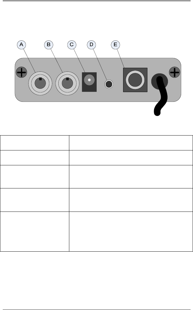
4.3 PROCESSING UNIT REAR PANEL
A. Rear Antenna Connection for rear antenna cable.
B. Front Antenna Connection for front antenna cable.
C. Speedometer
Input
Connection for the Speedometer pulse
cable.
D. Remote Control Connection for the wired remote
control cable.
E. Data Port RS232 I/O port provides information to
video systems or for updating operating
software. All operations of the Raptor
RP-1 can be controlled via this port.
SECTION 5—GENERAL THERORY OF OPERATION
5.1
5. GENERAL THEORY OF OPERATION
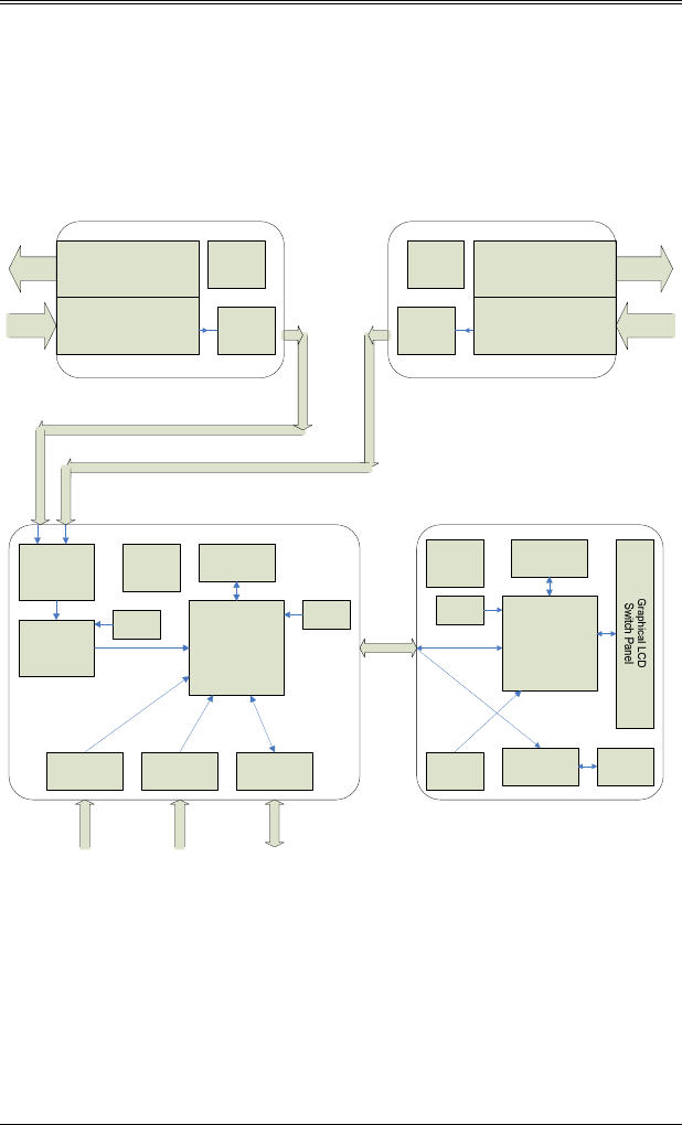
5.0 BLOCK DIAGRAM:
Flash
Micro-Controller
Speaker
Power
Supply
XTAL
Speaker
Amplifier
EE
Memory
DISPLAY UNIT
IR
Detector
Antenna
Switch
Analog to
Digital
Converter
Speedometer
Input
Remote
Control Input
XTAL
Data
Port
EE
Memory
XTAL
Flash
DSP
Power
Supply
PROCESSING UNIT
ANTENNA
Microwave
Transmitter
Receiver Mixers
PreAmplifiers
Power
Supply
ALC
Microwave
Transmitter
Receiver Mixers
PreAmplifiers
Power
Supply
ALC
ANTENNA

SECTION 5—GENERAL THERORY OF OPERATION
5.2
5.1 GENERAL
The Raptor RP-1 moving radar system transmits a K or Ka-
Band radio frequency in compliance with the Federal
Communications Commission (FCC) regulations.
CIRCUIT DESCRIPTION:
Antenna Description (K-Band)
: The Raptor RP-1 employs
a Doppler Radar Transceiver Module (integrated antenna
and micro-wave transceiver). The antenna element is a
Microstrip Patch Antenna Array (MSPA). The antenna has
one transmit and one receive array sections of connected
patch elements. The transceiver is an integrated microstrip
design containing the transmitter, low noise amplifier,
receiver mixers (I/Q), and pre-amplifiers. An electronic
board inside the antenna housing contains the power supply
and Automatic Level Control (ALC) circuitry. The output
signals from this antenna module are the I/Q Doppler
signals.
Antenna Description (KA-Band)
: The Raptor RP-1
employs a Doppler Radar Transceiver Module (integrated
micro-wave transceiver). The single antenna element is a
circular horn and lens type. The transmit and receive
sections are isolated by employing a turnstile junction in
the microwave wave guide. The microwave transmitter is a
Gunn effect oscillator placed at one port of the turnstile
junction. A pick-up probe at the other port of the turnstile
junction feeds the dual (I/Q) microstrip mixers. An
electronic board inside the antenna housing contains the
power supply and pre-amplifiers, filters and Automatic
Level Control (ALC) circuitry. The output signals from
this antenna module are the I/Q Doppler signals.
Processing Unit Description
: The outputs from the antenna
modules are connected to an antenna switch, to select the
active antenna between front and rear. The signals from
the active antenna are converted from continuous analog to
discrete digital samples by the analog to digital converter.
These digital samples are use by the DSP for all target

SECTION 5—GENERAL THERORY OF OPERATION
5.3
detection, directional phase sensing, and speed processing.
Other peripheral circuits in the processing unit are;
speedometer input, remote control input, and data
input/output. These circuits are not in the I/Q Doppler
signal path. The calculated target speed and direction
information data is sent to the Display unit.
Display Unit Description:
The micro-controller in the
display unit receives the data from the processing unit and
displays the information on the graphic LCD. Switch
presses from the front panel are detected by the micro-
controller and are sent to the processing unit. The display
unit also contains a IR detector for the optional IR remote
control and a speaker driver for the Doppler audio signal.
OPERATION DESCRIPTION:
Moving Mode
: In moving mode a portion of the
transmitted signal reflects from the surface of passing
stationary objects back to the antenna. This returning
signal is the "groundspeed" Doppler. From the antenna, it
travels to the Digital Signal Processor (DSP) where the
signal is translated to the speed of the patrol vehicle
(groundspeed) and is displayed for the operator to confirm.
Kustom Signals radar has a patented feature using the
patrol vehicle’s speed sensor pulses, which steers the DSP
processor to look for the “groundspeed” Doppler signal in a
specific speed range. This feature will eliminate the often-
annoying anomalies such as shadowing, combined patrol
speeds, splitting speeds, and displaying patrol speed when
stopped at a traffic light or sign.
Moving Opposite Direction Mode
: In moving opposite
direction mode, a portion of the transmitted signal strikes
an oncoming vehicle (target vehicle) and returns a Doppler
frequency higher than the groundspeed because the two
objects (patrol vehicle and target vehicle) are converging.
This returning signal is the "target" Doppler. The
processing unit measures this speed of convergence, or
combined speed.

SECTION 5—GENERAL THERORY OF OPERATION
5.4
Target Doppler Signal
: Upon receiving the "target"
Doppler signal, the processing unit automatically computes
the difference between the speed of the patrol vehicle and
the target vehicle. The speed of the approaching vehicle is
then displayed as the Target speed. If, for example, a patrol
vehicle is traveling 55 MPH and an approaching vehicle is
traveling 65 MPH, the Raptor RP-1 would process the
groundspeed of 55 MPH and the combined speed of 120
MPH. The DSP would subtract the patrol speed from the
combined speed (120 - 55 = 65). The Patrol would display
55 and the Target would display 65.
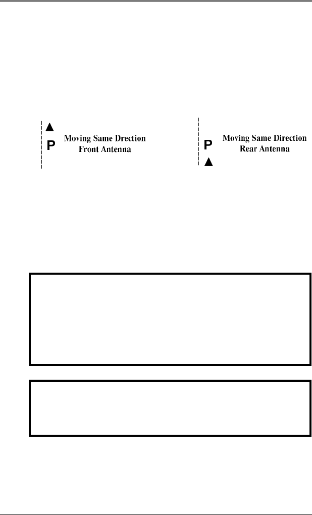
Moving Same Direction Mode
: In the moving same
direction mode of operation, the target Doppler is received
from a target traveling in the same direction as the patrol
vehicle. These "groundspeed" Doppler and the
"difference" Doppler signals are received and sent to the
DSP. The Difference Doppler is the speed difference
between the patrol vehicle and a vehicle traveling in the
same direction. The Raptor RP-1 uses its directional
determination capabilities to automatically determine if the
target vehicle is traveling faster or slower than the patrol
vehicle. The unit will display the patrol speed then
automatically add or subtract the "difference" speed to the
patrol speed for the target speed.
If the patrol vehicle's speed was 55 mph and a target was
traveling in the same direction at 70 mph, the Raptor RP-1
would display 55 as the Patrol then add the "difference”
Doppler signal (15) to the patrol speed (55 + 15 = 70) and
display 70 as the Target.

SECTION 5—GENERAL THERORY OF OPERATION
5.5
5.2 MICROWAVE RF EMISSIONS
Traffic radar operators may have some questions about the
biological effects of exposure to the microwave energy
produced by the radar devices. According to all credible
evidence, the emission levels resulting from traffic radar
use pose no threat whatsoever, either to the radar operator
or to target vehicle occupants.
One widely recognized authority for safe limits of
nonionizing radiation exposure is the American National
Standards Institute, which recommends maximum exposure
levels for the frequencies on which Kustom traffic radar
systems operate (ANSI/IEEE C95.1-1999, "Standard for
Safety Levels With Respect to Human Exposure to Radio
Frequency Electromagnetic Fields, 3 kHz to 300 GHz").
These exposure levels, expressed in terms of power density,
are 10 mW/cm² for K-band and Ka-band radar units.
Similarly, the Occupational Safety and Health
Administration (OSHA), a division of the U.S. Department
of Labor, recommends a 10 mW/cm² exposure limit for
both frequency bands ("Radiation Protection Guide", 29
CFR, Chapter XVII, Subpart G, Part 1910.97). This limit
is clearly accepted by most reputable scientific and medical
authorities.
Kustom radar systems utilize microwave transmitters that
produce aperture power densities, measured directly at the
face of the antenna, in the range of approximately 0.1 to 2.3
mW/cm2. Typical levels for the vast majority of units are
in the 0.4 to 1.0 mW/cm² range, which is but a small
fraction of the recognized safe limits. Bear in mind that
these are level measurements taken directly in the main
beam of the antenna, and that the power densities produced
at the sides and rear of the unit are typically at least one
hundred times lower than in the main beam.

SECTION 5—GENERAL THERORY OF OPERATION
5.6
Another reference document on this topic is a DOT
publication entitled "Field Strength Measurements of Speed
Measuring Radar Units" (NHTSA Technical Report #DOT-
HS-805 928). This report documents a series of tests
performed by the National Bureau of Standards on twenty-
two commonly used models of traffic radar units, from six
different manufacturers including Kustom. Aperture power
density levels measured were from 0.25 to 2.82 mW/cm²,
while back-lobe power density values ranged from 0.001 to
0.02 mW/cm². These measurements were obtained with
the radars mounted inside vehicles, as in normal operating
conditions. Since the NBS study, other laboratories have
duplicated these types of measurements, producing
consistently similar results.
For a free copy of the latest information regarding the safe
human exposure standards, please call or write Kustom to
request the "RF Emissions Packet." You may contact us at
our corporate headquarters:
Kustom Signals, Inc.
9325 Pflumm
Lenexa, KS 66215-3347
(913) 492-1400
While traffic radar devices do emit microwave energy, the
levels are so low that there are no probable harmful effects.
You may use your Kustom radar unit with complete
confidence in its safety, as well as in its accuracy.

SECTION 6—TESTING PROCEDURES
6.1
6. TESTING PROCEDURES
6.0 GENERAL
The tuning fork tests explained below should be conducted
at the beginning and end of each patrol shift to ensure the
accuracy and functionality of the unit. The results of these
tests may be recorded in a radar log, similar to the log
found at the end of this manual. The internal circuit and
antenna tests are periodically performed automatically
while the unit is in use.
6.1 POWER ON
Press and release the PWR switch. The unit will progress
through the power-up sequence; light all the LCD pixels,
test both antenna ports for connected antennas, and perform
a crystal cross check to verify the timing accuracy of the
speed processing circuitry.
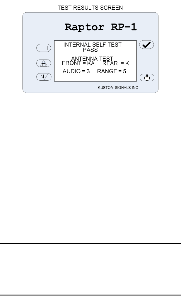
The results of these tests will be displayed on the test
results screen before progressing to the main enforcement
screen. The results of the Internal Self Test will be “PASS”
if all internal tests are within tolerance. If any of the
internal tests fails, the specific test failure will be reported,
such as “CRYSTAL FAILURE”. The band of each
antenna connected to the unit will be displayed (K, KA,
NONE). The current setting of the audio and range levels
are also displayed on this tests results screen. As well, the
audio is unsqelched to allow the user to hear the audio
level.
SECTION 6—TESTING PROCEDURES
6.2
6.2 AUTOMATIC SELF-TEST
As long as the unit is turned on, the Raptor RP-1performs
an internal accuracy test every 5 minutes or whenever the
unit’s mode of operation is changed, such as moving to
stationary, and each time the target speed is locked.
This test is automatic and will not interfere with any radar
speed readings being taken. The test passing does not
appear in the displays, but if an error is detected during this
test, the specific error message will be displayed in the
message area and further speed-readings are prohibited.
6.3 MANUAL TEST
The operator can manually perform the display and internal
tests at any time during normal radar operation—just press
and release the Test (√) switch. The display test will be
performed followed by the display of test results screen.
NOTE: The unit will remain in the TEST state for 30
seconds after releasing the TEST switch, indicated
by “FORK TEST” displayed in the message area.
Due to the ability of the unit to reject non
directional signals, the operator must place the
unit in this TEST mode to read tuning forks.

SECTION 6—TESTING PROCEDURES
6.3
6.4 TUNING FORK TESTING
Supplied with the Raptor RP-1 are two tuning forks, 35 and
65 mph. These tuning forks will simulate targets in the
stationary, moving opposite and moving same direction
modes.
The tuning fork tests should be conducted with the
antennas pointed away from traffic to avoid reflections
from moving vehicles.
** Due to the ability of the Raptor RP-1 to reject
non-directional signals, the operator must place the
unit in the FORK TEST mode to read tuning forks.
Momentarily depress the Test
(√)
switch. Upon
releasing this switch, the Raptor RP-1 will complete
the internal tests and enter the tuning FORK TEST
mode.
The unit will remain in this mode for 30 seconds,
indicated by the FORK TEST displayed in the
message area. Tuning fork tests may be performed
while in this mode. Changing to a new mode will
refresh the timeout to 30 seconds, allowing fork testing
in different modes without leaving the test mode.
Pressing the Test
(√)
switch again, while in the Test
mode, will terminate the Test mode.
SECTION 6—TESTING PROCEDURES
6.4
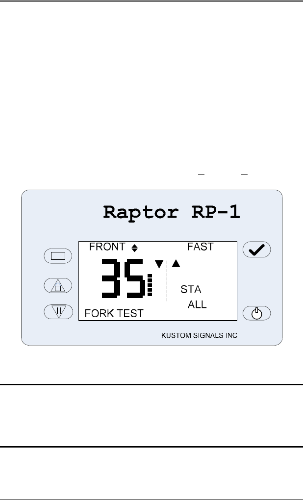
6.4.1 STATIONARY TUNING FORK TEST
1.
Place the Raptor RP-1 in the stationary “STA ALL”
mode of operation.
2.
Momentarily press the Test (√) switch to enter the Fork
Test mode. The message area will display FORK
TEST.
3.
Lightly strike the lower speed tuning fork on a hard,
nonmetallic surface. Place the fork in front of the
antenna. Make sure the antenna to be tested is active,
(not in HOLD). Verify a target speed display of the
value stamped on the tuning fork, +1 mph (+1 km/h).
5. Repeat for the higher speed tuning fork.
NOTE: Since the Raptor RP-1 can determine these fork
signals are non-moving targets, the speeds
displayed during the fork tests cannot be
LOCKED.
SECTION 6—TESTING PROCEDURES
6.5
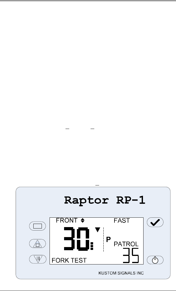
6.4.2 MOVING-OPPOSITE TUNING FORK TEST
1. Place the Raptor RP-1 in moving mode, opposite
direction. (Press the MODE switch on the remote to
select moving mode and the SAME/OPP switch remote,
if necessary, to select opposite direction.)
2. Ensure the antenna is active, (not in HOLD).
3. Momentarily press the Test (√) switch to enter the Fork
Test mode. The message area will display FORK
TEST. This allows the radar to detect a tuning fork and
bypasses the speedometer input if it is being used.
4. Lightly strike the lower speed tuning fork on a hard,
nonmetallic surface and place it in front of the antenna.
The PATROL area should read the speed stamped on
the tuning fork, +1 mph (+1 km/h).
5. While holding the lower speed fork in front of the
antenna, lightly strike the higher speed tuning fork and
place it in front of the antenna. The primary Target
area should display the difference between the lower
fork and the higher fork.
Target display tolerance is +1 mph (1 km/h).
SECTION 6—TESTING PROCEDURES
6.6
6.4.3 MOVING--SAME DIRECTION TUNING FORK
TEST
1. While in the moving mode, press the SAME/OPP
switch on the remote control and place the unit in the
Same Direction mode.
2. Momentarily press the Test (√) switch to enter the Fork
Test mode. The message area will display FORK
TEST. This allows the radar to detect a tuning fork and
bypasses the speedometer input if it is being used.
3. Lightly strike the higher speed tuning fork on a hard,
nonmetallic surface and hold it in front of the antenna.
The PATROL area should display the speed stamped on
the fork, +1 mph (+1 km/h).
4. While holding the high speed tuning fork in front of the
antenna, lightly strike the lower speed tuning fork and
hold it in front of the antenna. The primary Target area
should display the sum of the higher and lower speed
tuning forks.
Target display tolerance is +1 mph (+1 km/h).

SECTION 6—TESTING PROCEDURES
6.7
6.4.4 TUNING FORK TEST FAILURE
If the proper speed readings are not obtained during the
previous tests, check the following:
1. The Raptor RP-1 cannot test tuning forks if the system
is not in Test mode as indicated by the FORK TEST
displayed in the message area.
2. Verify that the tuning forks are the proper tuning forks
supplied with the unit.
3. Striking the tuning fork too hard or on a metallic
surface will cause spurious overtones from the tuning
fork. This may cause the speed readings to be double
the specified speed. Also, moving the tuning fork while
in front of the antenna may cause the speed reading to
be slightly lower or higher than specified. These
readings are only momentary and the proper readings
should appear as the false overtones dissipate.
NOTE: Do not move the tuning forks after they have been
placed in front of the antenna.
4. Ensure that the Raptor RP-1 is in the transmit mode and
the range control is set to maximum.
5. If the proper readings cannot be obtained, remove the
unit from service and contact Kustom Signals Service
Support. 1-800-835-0156 (620-431-2700)

SECTION 6—TESTING PROCEDURES
6.8
6.5 SPEEDOMETER VERIFICATION
Before the Raptor RP-1 can be used with the Vehicle Speed
Sensor (VSS) pulse input, the radar unit must be
synchronized with the speedometer. From the main
Enforcement screen follow these steps to synchronize with
the speedometer.
1.
After installation and initial testing with tuning forks,
the Raptor RP-1 should be driven at a constant speed,
between 40 and 70 mph (64 and 112 km/h). Press the
Menu switch to go to the main menu screen.
2.
Use the Up / Down buttons to highlight the
ADVANCED selection and press ENTER to go to the
Advanced menu screen.
3.
Use the Up / Down buttons to highlight the VSS
SETUP selection and press ENTER to go to the VSS
Setup screen. The current Synchronization number will
be displayed on this screen.
4.
Use the Up / Down buttons to highlight the SYNC TO
VSS selection and press ENTER to go to the Sync
Radar to VSS screen. The current Patrol Speed as read
by the Radar will be displayed on this screen.
5.
Verify the patrol speedometer and the radar patrol
speed displayed agree within reasonable limits, and
then press ENTER. This tells the radar that the current
speedometer pulses (speed) and the Doppler patrol
signal (radar patrol speed) agree

SECTION 6—TESTING PROCEDURES
6.9
NOTE:
Only the actual Doppler signal is used for
the Patrol Speed. The speedometer input is
used only to steer or guide the DSP to search
for the Patrol Doppler signal in a specific
area, ignoring signals in other areas.
6. During normal operation, at patrol speeds below the
minimum limit of 10 mph, 16 km/h, or when a
“groundspeed” Doppler signal cannot be found, the
PATROL area will display dashes (---), indicating that
the speedometer speed is being received but a patrol
speed cannot be found or displayed. As an example,
when a patrol vehicle is slowing down and the speed
drops below the minimum speed, dashes will be
displayed.

SECTION 6—TESTING PROCEDURES
6.10
6.6 MINIMUM PATROL SPEED SET
When the speedometer input feature is not used, the Raptor
RP-1 allows the operator to set a minimum patrol speed of
10, 20, 30 or 40 mph (16, 32, 48 or 64 km/h).
To activate this feature:
1.
Press the Menu switch to go to the main menu
screen.
2.
Use the Up / Down buttons to highlight the PAT
MIN selection and press ENTER. The current
Patrol minimum setting will be blinking.
3.
Use the Up / Down buttons to change the patrol
minimum setting to 10, 20, 30, or 40 mph. Press
ENTER to save the new setting. Press ENTER
again to exit the menu screen.
NOTE: The lowest value (10 mph/16 km/h) is the default
setting. At this setting the typical patrol speed
readings will be 6 mph / 10 km/h.
6.7 MOVING MODE TEST
Verification of speed readings between the patrol vehicle's
speedometer and the Raptor RP-1’s PATROL speed
display is another accuracy test that can be performed.
These readings should be the same, or within reasonable
limits, allowing for minor speedometer error.
Speedometer checks should be done on a daily basis. If a
discrepancy is found, the radar unit should be removed
from service until the error can be corrected.

SECTION 7—OPERATION
7.1
7. OPERATION
7.0 OPERATING MODES
The Raptor RP-1 radar system offers the operator one of
the most versatile traffic radar systems available today. It
can be used in 10 different operating modes.
1.
Stationary ALL Front Antenna
2.
Stationary ALL Rear Antenna
3.
Stationary Approaching Only Front Antenna
4.
Stationary Approaching Only Rear Antenna
5.
Stationary Receding Only Front Antenna
6.
Stationary Receding Only Rear Antenna
7.
Moving Opposite Direction Front Antenna
8.
Moving Opposite Direction Rear Antenna
9.
Moving Same Direction Front Antenna
10.
Moving Same Direction Rear Antenna
NOTE:
The following guide to operating the Raptor
RP-1 radar system is not intended to be a training
program. Before operating this unit or any other
traffic radar system, Kustom Signals recommends
that all operators have prior training in radar
speed monitoring devices. Such courses are
offered by Kustom Signals, various state and
local agencies and either IPTM (Institute of
Police Technology and Management) or
Northwestern University.

SECTION 7—OPERATION
7.2
7.1 OPERATIONAL SETUP
1. Select a location that provides a good view of the traffic
to be monitored.
2. Check the immediate area for potential interference
sources, such as large reflecting signs in the direct path
of the radar's microwave beam, power substations and
other sources of electrical interference.
3. Position the patrol vehicle in a safe location, with easy
access to the roadway.
NOTE: Cosine effect, the angle between the target’s
direction of travel and the path to the radar, in the
stationary mode, will ALWAYS be in the driver’s
favor. Refer to the National Highway Traffic
Safety Administration’s “Basic Training Program
in RADAR Speed Measurement” for speed
reduction information due to cosine angle.
7.1.1 POWER ON / OFF
To power on the Raptor RP-1, press and release the power
switch in the lower right-hand corner of the display head.
To power down the unit press and hold the power switch.
If the switch is held down for just over one second the unit
will power down.
7.1.2 BACKLIGHT CONTROL
For low light operation, the Raptor RP-1 has a multi-level
backlight. After power up, the power switch in the lower
right-hand corner of the display head is used to set the level
of the backlight. The level settings for the backlight are;
off, ½, ¾, and full. On power up the default backlight level
is set to ½. By pressing and releasing the power switch, the
backlight level setting is rotated through ½ - ¾ - full – off –
½.

SECTION 7—OPERATION
7.3
7.1.3 ADJUSTING
A
UDIO
Adjust the Doppler audio for the desired listening level.
Press the Menu switch to get to the menu screen. Use
the Up / Down buttons to highlight the AUDIO selection
and press ENTER. The current Audio level setting will be
blinking. Use the Up / Down buttons to set the desired
audio level (1 – 5). Press ENTER to save the new setting.
Press ENTER again to exit the menu screen.
While setting the Audio level (Audio level blinking), the
user can toggle the Audio Squelch / UnSquelch setting by
pressing the Test(√) switch.
7.1.4 ADJUSTING RANGE
Set the range control to the desired level. Press the Menu
switch to get to the menu screen. Use the Up / Down
buttons to highlight the RANGE selection and press
ENTER. The current Range level setting will be blinking.
Use the Up / Down buttons to set the desired Range level (1
– 5). Press ENTER to save the new setting. Press ENTER
again to exit the menu screen.
Range level 5 is maximum range; range level 1 reduces the
Raptor RP-1 range to its minimum distance.
SECTION 7—OPERATION
7.4
7.2 STATIONARY OPERATION
The Raptor RP-1 has six modes of stationary operation:
•
All (ALL) - front antenna: Targets in front of the
patrol vehicle from both directions are displayed
and the direction of travel is indicated.
•
All (ALL) - rear antenna: Targets behind of the
patrol vehicle from both directions are displayed
and the direction of travel is indicated.
•
Approaching only (APR ONLY) - front antenna:
Approaching targets in front of the patrol vehicle
are displayed, receding vehicles not displayed.
•
Approaching only (APR ONLY) - rear antenna:
Approaching targets behind the patrol vehicle are
displayed, receding vehicles not displayed.
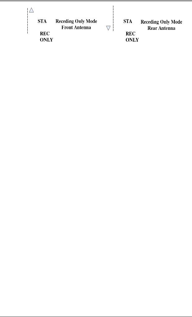
•
Receding only (REC ONLY) - front antenna:
Receding targets in front of the patrol vehicle are
displayed, approaching vehicles not displayed.
•
Receding only (REC ONLY) - rear antenna:
Receding targets behind the patrol vehicle are
displayed, approaching vehicles not displayed.
SECTION 7—OPERATION
7.5
Stationary Setup:
1.
Place the unit in the desired stationary mode. Switch to
the desired antenna (Front / Rear). Set range and audio
to the desired level.
2.
*If desired, turn the microwave transmitter off by
pressing the remote control HOLD switch for the
selected antenna or by pressing the front panel Hold
switch. "HOLD" will be displayed in the message area
and above the Target area.
3.
Complete a tracking history on the target vehicle.
A.
Observe the target and surrounding traffic.
B.
Estimate the speed of the target vehicle.
C.
*Depress the HOLD switch to turn the microwave
transmitter on.
D.
Listen to the pitch of the audio; it should
correspond to the estimated speed.
E.
Observe the speed-reading shown in the Raptor
RP-1’s Target area display. It should correspond
with B and D above.
F.
Observe the indication of the target's direction of
travel from the road graphics indicator. It should
correspond to the observed target's direction of
travel.
G.
If any of the above elements are incompatible, the
reading must be disregarded.
* Use the HOLD feature to defeat radar detectors.

SECTION 7—OPERATION
7.6
7.2.1 TAGET LOCK - STATIONARY OPERATION
1.
If the operator wishes to lock (retain) the violator's
speed, simply depress the LOCK switch on either the
remote control or the front panel. A short alert tone
will be heard and the target speed will be displayed in
the LOCK area.
The Raptor RP-1 will continue to track the violator's
speed in the Target area as long as the vehicle is in the
antenna beam.
The Raptor RP-1 will automatically run internal tests
prior to locking any speed. Depressing the Test(√)
switch will allow the unit to complete a display,
antenna, and internal test then return the locked speed.
If the operator switches to the opposite antenna while
Locked, the road graphic indicator for the selected
antenna at the time of lock will flash and the new
selected antenna will be on. If the operator changes
back to the original antenna, the original antenna
indicator will light steady.
While Locked the operator can not change the mode of
operation, such as stationary to moving.
2.
To manually unlock or clear the locked speed, again
depress the LOCK/REL switch on either the remote
control or front panel. This will clear the LOCK
display area.
NOTE: If the auto-unlock option is enabled, the locked
speed will be automatically unlocked after 14
minutes.

SECTION 7—OPERATION
7.7
7.2.2 FASTEST MODE--STATIONARY OPERATION
1.
The Fastest vehicle operation to be toggled on / off, by
the FAST switch on the remote control. When the
fastest mode is activated, “FAST” will be displayed
above the FAST area.
2.
When a fastest vehicle is detected, the Fast area will
display the speed of the fastest vehicle and the arrow
symbol above the Fast area will display the direction
the fastest vehicle is traveling. (The primary target area
will continue to display the speed of the strongest target
vehicle.)
NOTE: This is especially useful in traffic situations such
as a small vehicle overtaking a larger truck. In the
FASTEST mode, as in normal radar operation, a
good tracking history is essential.
3.
The operator may lock the fastest speed by depressing
the LOCK switch while a fastest speed is displayed.
The strongest speed may be locked by depressing the
LOCK switch when only the strongest speed (no fastest
speed) is being displayed.
4.
When the speed is locked, a short alert tone will be
heard. The label above the FAST / LOCK area will
change to “LOCK”, and the locked target speed will be
displayed in the Lock area.
If the fastest vehicle's speed was locked, the primary
Target area will display the current fastest target (for
track-through-lock history), and the message area will
display “FAST TRACKING”. When there is no target
being tracked, the message area will display “FAST
LOCKED” to indicate the locked speed was obtained as
a fastest speed.

SECTION 7—OPERATION
7.8
If the strongest vehicle speed was locked, the primary
Target area will continue to display the strongest target
and the FAST label above the Fast / Lock area will be
replaced with “LOCK”, indicating the locked speed was
obtained as a strongest speed.
5.
To manually unlock or clear the locked speed, again
depress the LOCK/REL switch on either the remote
control or front panel. This will clear the LOCK
display area.
NOTE: If the auto-unlock option is enabled, the locked
speed will be automatically unlocked after 14
minutes.
SECTION 7—OPERATION
7.9
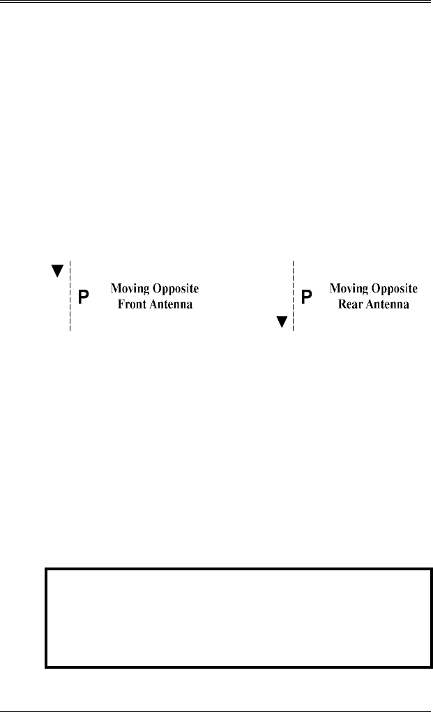
7.3 MOVING MODE—OPPOSITE DIRECTION
1.
Place the Raptor RP-1 in the moving mode by pressing
the Mode switch, if needed, until the “PATROL” label
is displayed above the Patrol area and ‘P’ is displayed
in the road graphic. If necessary, select Opposite
Direction mode by pressing SAME/OPP switch on the
remote control (the opposite road graphic indicator will
be lit).
2.
Select the desired antenna, front or rear by pressing the
Front Hold or Rear Hold switch on the remote control.
3.
If the speedometer input feature is not used, check the
setting of the minimum patrol speed. To display the
existing patrol minimum setting, press the Menu
switch to go to the main menu screen. To change the
patrol minimum setting, refer to Sec. (6.6).
3. While driving, observe traffic and complete a tracking
history on the target vehicle as described in Section 7.2
Step 3 and verify the radar’s patrol speed reading with
the patrol vehicle’s speedometer. When all elements
agree, enforcement action may be taken.
NOTE:
If an incorrect Patrol speed is obtained, the
operator can go in and out of HOLD quickly.
This will clear all previous speeds, and a new
patrol speed search will be initiated. See
Sec. 7.7

SECTION 7—OPERATION
7.10
7.3.1 HOLD MODE – MOVING OPPOSITE
The Raptor Rp-1 may be placed in the Hold mode (non-
transmit) by pressing selected antenna’s Hold switch on the
remote control (“FRNT HOLD” or “REAR HOLD” or
pressing the front panel Hold switch. “HOLD” will be
displayed in the message area and above the primary target
area. To return to normal radar operation, one of the Hold
switches again.
7.3.2 MOVING MODE – TARGET LOCK
1. To lock the target speed reading, press the LOCK
switch on the remote control or the front panel. A short
alert tone will be heard, and the Locked target speed
will be displayed in the Lock area.
2. The Raptor RP-1 will continue to track the target and
patrol speeds.
3.
When the patrol vehicle’s speed has dropped 10 mph
(16 km/h) below the speed when lock was activated, or
the unit is placed in Hold, the patrol vehicle’s speed, at
the time of lock, will flash in the Patrol area. This
allows the operator to continue to track the target while
monitoring the patrol vehicle’s speed and still retain the
locked patrol speed.
Note: While Locked the operator can not change the mode
of operation, such as stationary to moving.
4. The locked speeds may be unlocked by:
A. Pressing the remote control or front panel Lock
switch again.
B. Auto-unlock after 15 minutes, if activated.

SECTION 7—OPERATION
7.11
7.3.3 MOVING MODE – FASTEST VEHICLE
A Fastest vehicle target is a target that is traveling at a
higher speed that the strongest target vehicle.
1. With the unit operating in the moving mode, observe
traffic.
2. The Fastest operation can be turned on /off by pressing
the “FAST” switch on the remote control. When the
fastest mode is activated, the FAST label will be
displayed above the Fast area.
3. When a fastest target is detected, the fastest speed will
be displayed in the Fast area. The directional arrow
symbol above the Fast area, indicating approaching
fastest or receding fastest, will indicate the direction of
travel of the fastest target. The primary Target area will
continue to display the strongest signal speed.
7.3.4 MOVING MODE – FASTEST VEHICLE LOCK
1. To lock the fastest vehicle speed, momentarily press the
LOCK switch on the remote control or front panel.
2. If the fastest vehicle speed is locked, the primary Target
window will display the current fastest target (for track-
through-lock history) and “FAST TRACKING” will be
displayed in the message window. If the strongest
vehicle speed is locked, the primary Target window
will continue to show the strongest target, and the
FAST indicator will be turned off, indicating the locked
speed was obtained as a strongest target.
SECTION 7—OPERATION
7.12
7.4 MOVING MODE – SAME DIRECTION
(OPTIONAL FEATURE)
1. Select the moving mode, same direction by pressing the
SAME/OPP switch on the remote control. The same
direction road graphic indicator will be lit.
2. While driving, observe traffic traveling the same
direction as the patrol vehicle.
3. Complete a tracking history as in Sec 7.2 step 3, and
verify the patrol speed agrees with the speedometer
speed reading.
NOTE:
Vehicles traveling at the same rate of speed as
the patrol vehicle will not qualify as targets. The
minimum difference in speed between the patrol
vehicle and the target vehicle is 3 mph (5 km/h).
The maximum difference is 0.65 x Patrol Speed
(65% of Patrol Speed). (For a patrol speed of 50
mph, the maximum difference speed would be 32.
NOTE:
If an incorrect Patrol speed is obtained, the
operator can go in and out of HOLD quickly.
This will clear all previous speeds, and a new
patrol speed search will be initiated. See Sec. 7.7
4.
The Raptor RP-1 can automatically detect whether the
target vehicle is traveling slower or faster than the
patrol vehicle. There is no need for the operator to
input slower or faster information for same-direction
targets.

SECTION 7—OPERATION
7.13
5. The Fastest feature can also be used in the Same
Direction mode. To qualify as a fastest speed, the
target must be faster than both the strongest target and
the patrol speed.

SECTION 7—OPERATION
7.14
7.5 VSS PULSE OPERATION
The Raptor RP-1 has hardware and software in place to
interface the unit to the patrol vehicles speed sensor (VSS).
The speed sensors input pulses steer the DSP in the search
for the Doppler patrol signal. This patented technique,
(TruTrak) virtually eliminates problems of patrol
shadowing and patrol combining.
Once the synchronization procedure has been completed no
further action is needed unless the Raptor RP-1 is placed in
another patrol vehicle. If so, the operator must repeat the
synchronization procedure for the new vehicle if he wishes
to use the speedometer pulse input.
The radar may be operated with or without the speedometer
pulse input. If it is not connected to the speedometer pulse
input, it will operate as standard directional radar. If the
Raptor RP-1 is connected to the speedometer pulse input, it
will operate as a standard directional radar on power up.
When speedometer pulses are detected, it will
automatically begin using the stored synchronization code.
7.5.1 AUTOMATIC MODE SWITCHING
The Raptor RP1 with speedometer interface that has
been synchronized will perform
A
utomatic
M
ode
S
witching (AMS). When the unit has received
speedometer pulses, after power up, it will automatically
switch to moving mode while the vehicle is traveling and to
stationary mode when the vehicle stops.
NOTE:
AMS will not change modes if the operator has
Locked speeds. If speeds were Locked in
stationary mode and then the vehicle begins
traveling, the unit will be placed in Hold.

SECTION 7—OPERATION
7.15
7.6 SMART PATROL SEARCH
The Raptor RP-1 can be operated with or without
speedometer input. If the speedometer input is not
connected, the unit will use patented Smart Patrol Search
(SPS) software routines. This software reduces patrol
shadowing and patrol combining when coming out of Hold
mode by knowledge of how traffic radar is typically used
by the operator.
When using traffic radar in moving mode, typically the
operator will activate and deactivate the antenna transmitter
as needed to check the speed of target vehicles. The radar
may have been in Hold anywhere from several seconds to
several minutes. Each time the operator switches from
Hold to active mode, the unit must first capture the patrol
vehicle speed before any target speeds are processed. It is
during this initial capturing from Hold that radar processing
is the most vulnerable to patrol shadowing or combining.
SPS software works by storing the patrol speed when the
operator enters the Hold mode. This has two purposes; to
help track and/or reject patrol signals when returning to
active mode. If the unit is in the Hold mode for a typical
amount of time (more than one second), the DSP will
search first in a region around the stored patrol speed.
Example: The patrol vehicle is traveling 65 MPH and the
operator enters Hold mode. When the operator comes out
of Hold sometime later, the SPS software will search the
region around 65 MPH first for the patrol signal. If a 20
MPH shadowing signal was present, it is not likely to be
displayed as a false patrol.
SECTION 7—OPERATION
7.16
If on the other hand the unit is not in Hold for the typical
amount of time (less than one second), the region around
the saved patrol will be excluded from the initial patrol
search.
Example: The patrol vehicle is traveling 25 MPH, there is
a strong approaching target traveling 45 MPH, and the
radar has mistakenly combined the two and is displaying 70
MPH for patrol. The operator can quickly go in and out of
Hold to reject the region around 70 MPH and the correct 25
MPH patrol speed will be displayed.
7.7 MENU SCREEN MODES
The Raptor RP-1 has a graphical LCD display panel. This
allows the operator to make operational and configuration
options setup selection using full text menu screens.
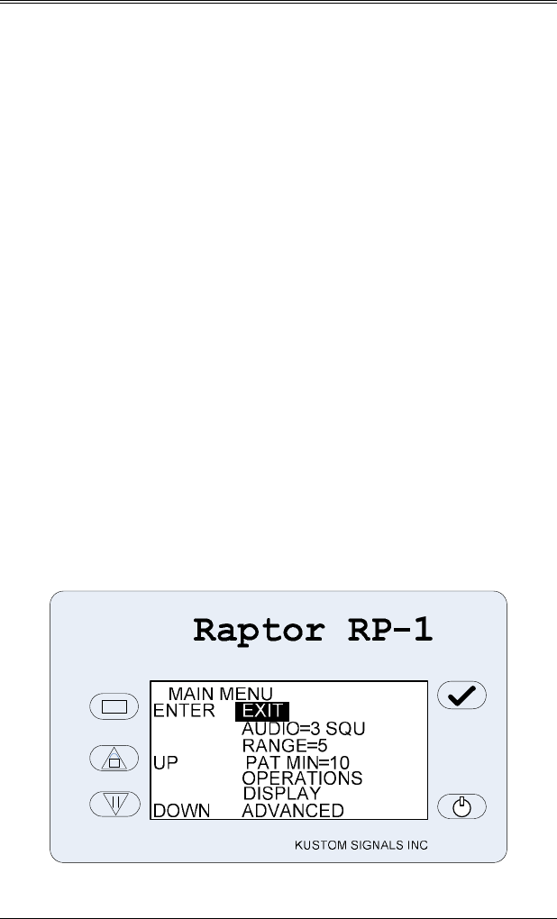
7.7.1 MAIN MENU SCREEN
The highest level of the menu screens is the main menu. To
get the main menu press the Menu switch. To select one
of the menu options, use the Up and Down switches to
highlight the option and then press the Enter switch.
SECTION 7—OPERATION
7.17
To adjust the Audio, Range, or Patrol Minimum setting,
once the option has been selected the current setting will
blink, use the Up or Down switches to adjust the setting.
Once the setting is at the desired level, press the Enter
switch to save the setting. The highlight will return to the
EXIT line.
To move to the Operations, Display or Advanced menus,
use the Up or Down switches to highlight the desired menu
and then press the Enter switch.
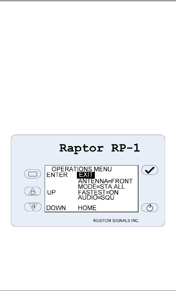
7.7.2 OPERATIONS MENU SCREEN
The Operations menu allows the user to change operational
settings of the Raptor RP-1 that are normally controlled via
the wired or IR remote control. By having this operations
menu the user can continue to control the Raptor RP-1 in
cases of a lost or broken remote control.
To select one of the operational settings, use the Up and
Down switches to highlight the desired item and then press
the Enter switch. The current setting will blink, use the
Up or Down switches to adjust the setting. Once the
desired setting is displayed, press the Enter switch to save
the setting and the highlight will return to the Exit line.
Choices for the Operational settings are:
Antenna: Front, Rear
SECTION 7—OPERATION
7.18
Mode: Stationary Approaching Only (STA APR),
Stationary Receding Only (STA REC), Stationary
All (STA ALL), Moving Opposite (MOV OPP),
Moving Same Direction (MOV SAME)
Fastest: On, Off
Audio: Squelch (SQU), UnSquelch (UNSQU)
Pressing Enter while the EXIT line is highlight will return
to the main menu screen. Pressing Enter while the HOME
line is highlighted will leave the menu screens and return to
the normal operation mode.
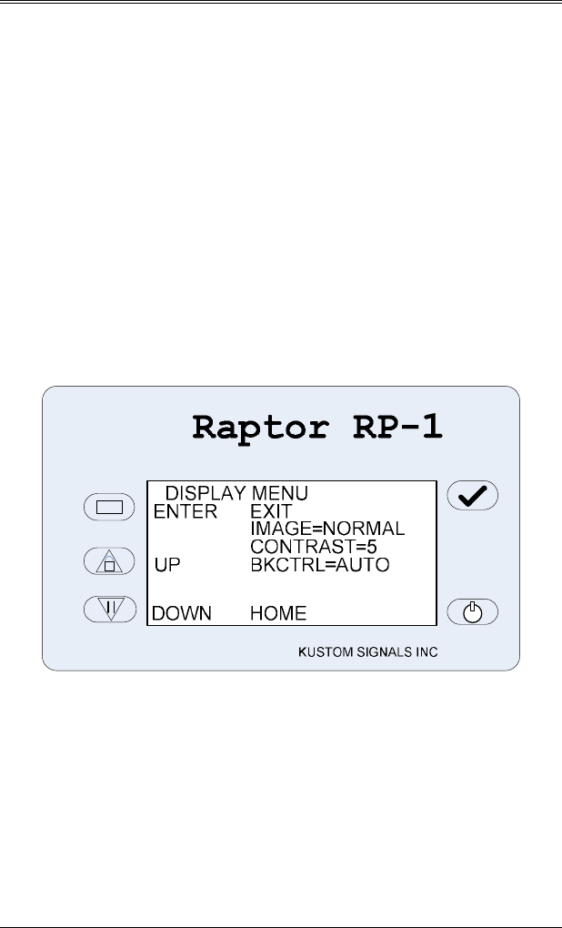
7.7.3 DISPLAY MENU SCREEN
The Display menu allows the user to change settings for the
LCD display.
To select one of the display settings, use the Up and Down
switches to highlight the desired item and then press the
Enter switch. The current setting will blink, use the Up
or Down switches to adjust the setting. Once the desired
setting is displayed, press the Enter switch to save the
setting and the highlight will return to the Exit line.
Choices for the Display settings are:
Image: Normal, Reverse
Contrast: 1 – 5
Back-Light: Manual, Automatic
SECTION 7—OPERATION
7.19
Pressing Enter while the EXIT line is highlight will return
to the main menu screen. Pressing Enter while the HOME
line is highlighted will leave the menu screens and return to
the normal operation mode.
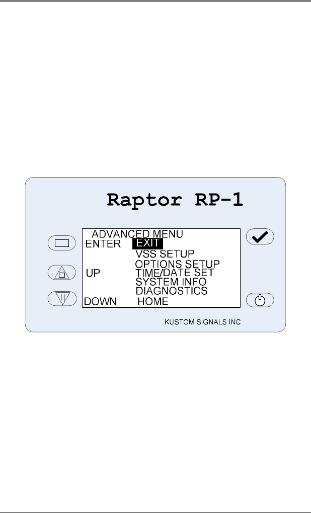
7.7.4 ADVANCED MENU SCREEN
The Advanced menu allows changes to of the Raptor RP-1
that are rarely are not normally set by the user. By having
this advanced menu the user can synchronize to the vehicle
VSS signal, set configuration options, set the optional Time
and Date, view system information, or run system
diagnostics.
To select one of the menu options, use the Up and Down
switches to highlight the option and then press the Enter
switch.
Pressing Enter while the EXIT line is highlight will return
to the main menu screen. Pressing Enter while the HOME
line is highlighted will leave the menu screens and return to
the normal operation mode.
SECTION 7—OPERATION
7.20
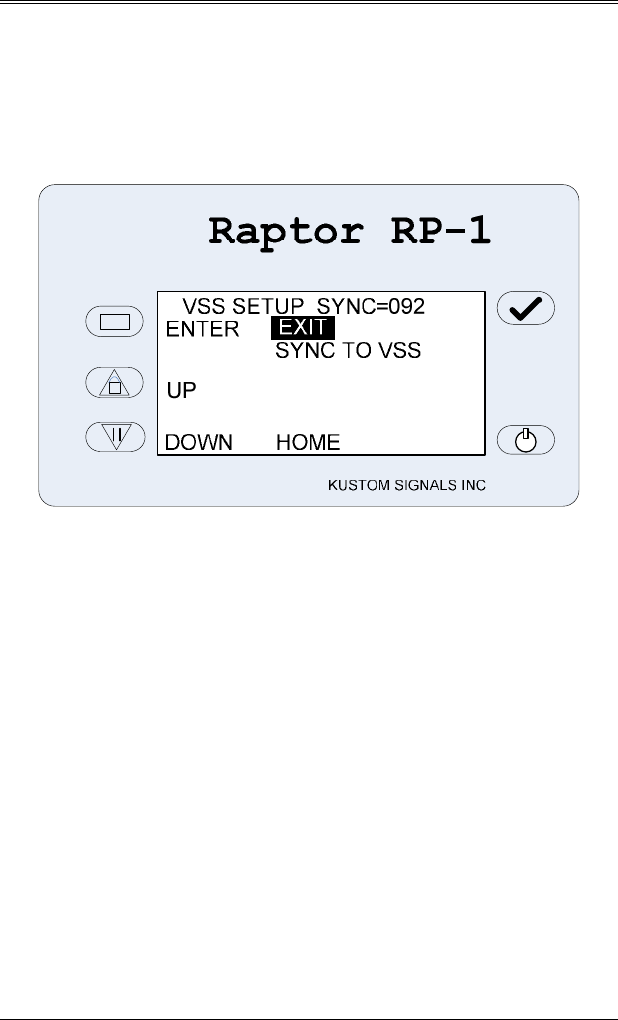
7.7.5 VSS SETUP MENU SCREEN
The VSS setup menu allows the user to synchronize the
Raptor RP-1 to the vehicles speed sensor (VSS) signal.
Follow the steps in Section 6.5 to complete the
synchronization.
Pressing Enter while the EXIT line is highlight will return
to the Advanced menu screen. Pressing Enter while the
HOME line is highlighted will leave the menu screens and
return to the normal operation mode.

SECTION 7—OPERATION
7.21
7.7.6 OPTIONS SETUP MENU SCREEN
The Options setup menu allows the user to set Raptor RP-1
configuration options.
Raptor RP-1
KUSTOM SIGNALS INC
OPTIONS PAGE1 MENU
ENTER
UNITS=MPH
AUTOUNLOCK=OFF
UP MIN AUDIO=0
ROADSIDE=RIGHT
SERIAL=KSI
DOWN NEXT PAGE
EXIT
Choices for the configuration options settings are:
Units: MPH, Km/H
Auto UnLock: Off, On
Minimum Audio Setting Allowed: 0, 1
Driver’s Roadside: Right, Left
Serial Output Format: KSI, Full Gateway, Reduced
Gateway, Test
Pressing Enter while the EXIT line is highlight will return
to the Advanced menu screen. Pressing Enter while the
NEXT PAGE line is highlighted will go to more future
options listings.
SECTION 7—OPERATION
7.22
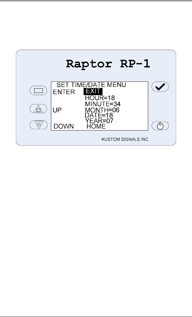
7.7.7 TIME / DATE SETUP MENU SCREEN
The Time / Date setup menu allows the user to set Raptor
RP-1 current time and date. *This is a non-standard,
optional feature.
To adjust the Hour, Minute, Month, Date, or Year, use the
Up / Down switches to highlight the desired selection and
then press the Enter switch. Once the item has been
selected the current setting will blink, use the Up or Down
switches to adjust the setting. Once the setting is at the
desired level, press the Enter switch to save the setting. The
highlight will return to the EXIT line.
Pressing Enter while the EXIT line is highlight will return
to the Advanced menu screen. Pressing Enter while the
HOME line is highlighted will leave the menu screens and
return to the normal operation mode.
SECTION 7—OPERATION
7.23
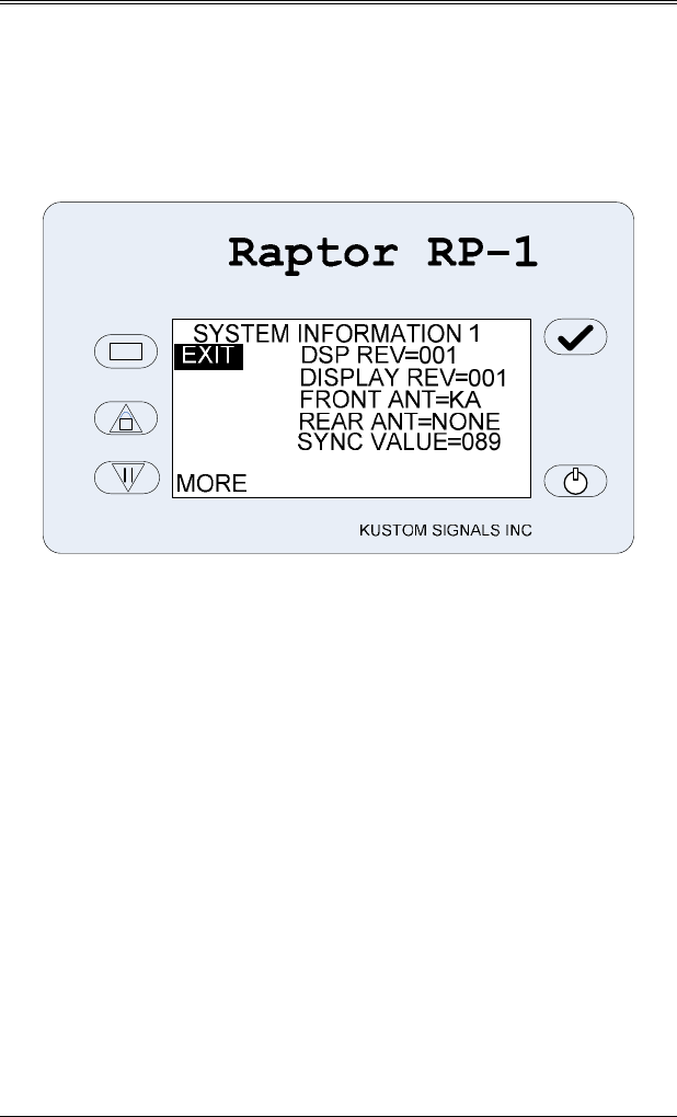
7.7.8 SYSTEM INFORMATION MENU SCREEN
The System Information menu screens allow the user to
view information about their Raptor RP-1 units. This
information includes software revisions, type of antennas
connected, VSS sync value, and enabled features.
There are no user’s settings in these menu screens.
SECTION 7—OPERATION
7.24
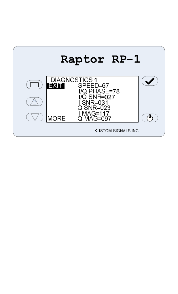
7.7.9 DIAGNOSTICS MENU SCREEN
The Diagnostics menu screens are not for normal users
operation. These menu screens are to augment
troubleshooting and for test lab operations.
There are no user’s settings in these menu screens.

SECTION 8—INFLUENCES AND INTERFERENCE
8.1
8. INFLUENCES AND INTERFERENCE
Interferences from external sources may affect the standard
operation of any radar device, including the Raptor RP-1.
These influences can be natural or man-made, however, the
Digital Signal Processing circuitry will eliminate most of
these influences and a knowledgeable operator should be
able to determine the nature of the influences and their
effect, if any, on the performance of the Raptor RP-1.
8.0 NATURAL INFLUENCES
1. Heavy rains and blowing dust can cause a scattering
effect, which may reduce the effective range of the
Raptor RP-1. The patrol speed can also be affected by
driving rain. It is recommended that the operator
compare the patrol speed reading and the speedometer
reading frequently during rainy periods.
2. Terrain can affect the range of the Raptor RP-1.
Improper aiming of the antenna can cause the radar to
appear to have short range. If the target vehicle were
on a slight incline, the antenna could be shooting short
of the intended target vehicle.
3. Strong reflections from roadside objects, such as large
signs, parked cars and buildings can cause double
bounce reflections, which appear to be targets traveling
at the same speed as the patrol vehicle. The DSP will
analyze signals that are the same as the patrol speed, if
it is determined they are possible “harmonics” from
double bounce the Target area will be blank or display
“- - -“ until this condition no longer exists.

SECTION 8—INFLUENCES AND INTERFERENCE
8.2
8.1 MAN-MADE INFLUENCES
1. Radar units may display incorrect speed readings from
various sources. These include shadowing, combined
speeds, moving cosine and fan interferences (splitting
speeds).
2. Patrol speed shadowing may occur when the radar unit
receives a stronger reflected signal from a vehicle
traveling the same direction than the groundspeed
return signal of the patrol vehicle. This difference
speed may be placed in the Patrol area and used instead
of the proper patrol speed. See Sec. 8.2.
3. The combined speed effect can occur when the patrol
vehicle and the target vehicle are approaching each
other at low speeds, usually in the 25 to 35 mph (40 to
56 km/h) range each, and at relative short distances,
usually less than 300 feet. The radar unit sees a strong
reflection from the combined speed signal and may
display this speed instead of the true patrol speed.
NOTE: The Raptor RP-1 with speedometer input will
eliminate these shadowing and combining
effects, and display the proper patrol and
target speeds. If the speedometer input is not
used, the Raptor RP-1 has patented software
algorithms that allow the radar to correct
shadowing or combined readings. If the user
suspects that the radar is displaying a shadow
or combined speed, entering and exiting the
Hold Mode quickly should correct the readings.
4. The Raptor RP-1 has an input power monitor. If the
power supply voltage drops below the minimum
operating voltage, the unit will not display any new
speed-readings until the low voltage condition no
longer exists. "LOW VOLTAGE" will be displayed in
the Message area.

SECTION 8—INFLUENCES AND INTERFERENCE
8.3
5. Radio Frequency Interference (RFI) exists when there
are strong RF transmitters in the immediate area of the
radar unit, such as the patrol vehicle’s transmitting
radio, high power radio or television stations. Normally
these signals are processed as non-moving and not
displayed as targets. However, if the RFI signals are
strong enough, the Raptor RP-1 will detect these
sources of interference. The unit will not display any
new speed-readings and the “RFI ERROR” will be
displayed in the Message area, until the source of
interference is reduced or eliminated.
6. Heater and A/C fan motors can cause a radar unit to
display the fan’s speed, rather than a weaker target
vehicle’s speed. A trained operator should not be
confused by intermittent fan readings and the distorted
audio. Proper antenna mounting, placement, and
aiming will eliminate most of the potential fan
interferences.
NOTE:
If there are still problems with fan interference
in your type of patrol vehicle, Kustom Signals
can provide antenna noise reduction pads to
prevent the fan signal from reaching the
antennas. Contact your District Sales Manager
or Kustom Signals' Customer Service
department for antenna pad options.
NOTE: Refer to the National Highway Traffic Safety
Administration’s Basic Training Program in
RADAR Speed Measurement for further
information on interferences and training guides.

SECTION 8—INFLUENCES AND INTERFERENCE
8.4
8.2 GROUNDSPEED
True groundspeed of the patrol vehicle is required by all
moving traffic radar systems before a target vehicle’s speed
can be accurately computed. If the Raptor RP-1 loses
correct groundspeed, the operator can recapture
groundspeed by quickly activating and then deactivating
the HOLD mode.
If the speedometer input is being used with the Raptor RP-
1, the DSP will accurately track even a weak patrol speed
return due to the small tracking window, unlike radar
without speedometer input.
The Raptor RP-1 will always look for and display
groundspeed before displaying any targets. The
groundspeed radar signature is unlike most target or
interference signals. The DSP can identify this pattern,
which is helpful in situations such as shadowing or
combined speeds. While the speedometer input and DSP
technology will eliminate most of the influences found in
moving radar, it is still the responsibility of the operator to
complete a tracking history on the target vehicle and verify
the patrol speed with the patrol vehicle’s speedometer.
Close observation of the patrol vehicle’s speed reading is
recommended to avoid possible confusion.
NOTE:
Typically the Raptor RP-1 will not display
patrol speeds below 6 mph (10 km/h), or
below the patrol minimum setting if the
speedometer input is not used.
Operating moving radar in the rain and snow requires the
operator to pay close attention to the patrol speed. Since
rain, fog and snow may affect the ability of the radar
system to find groundspeed, the operator must verify the
displayed patrol speed reading is correct.

SECTION 9—CARE OF THE RAPTOR RP-1
9.1
9. CARE OF THE RAPTOR RP-1
The Raptor RP-1 radar system is designed for long reliable
use by law enforcement agencies. Following basic care
guidelines will ensure the unit gives many years of trouble-
free service.
9.0 ROUTINE CARE
1. Use a damp cloth to clean the outside of the radar unit if
it becomes dirty. DO NOT use excessive water or any
cleaners or sprays on the outer surfaces of the unit or
remote control.
2. As with all electrical or electronic equipment, protect
the unit from water. While all parts are weather
resistant, the processing unit and remote control are not
waterproof. If any liquid should get inside, remove
power immediately and send the unit in to a repair
facility. Prompt action can minimize any damage.
3. If the Raptor RP-1 is used outside in rain or snow, it
should be wiped dry with a clean cloth as soon as
practical.
4. There are no user serviceable parts inside the Raptor
RP-1. All major circuit boars (main processing,
display, antenna) have over-current protection by
automatically resetting fuses. There is one main fuse
located in the end of the cigarette lighter plug. If
needed, simply unscrew the tip and replace with the
same size fuse.
5. Do not pick up or carry the Raptor RP-1 by the power
or remote control cables. Broken power, antenna, and
remote control cables are a common cause of
intermittent operation.

SECTION 9—CARE OF THE RAPTOR RP-1
9.2
6. Kustom Signals recommends periodic maintenance and
certification of the Raptor RP-1 radar system. Check
with your local judicial district for requirements.
9.1 EQUIPMENT REPAIR/RETURN
Should the Raptor RP-1 need repair or certification from
Kustom Signals Customer Service, please visit our website
(www.kustomsignals.com ), click on the “parts & returns”
tab and follow the instructions on the Returns Form to
receive a Return Material Authorization (RMA) number. If
you do not have access to our website, please call our
Customer Service Department at (800) 835-0156 or (620)
431-2700 to obtain your RMA number before returning
your unit. The following information will be needed:
1. Serial number of unit, department name, return
shipping address, contact name at owning department,
and phone number.
2. Complete description of failure or problem with unit.
Please describe, in detail, what the failure is and when it
is observed. EXAMPLE: In moving mode, targets are
close to patrol vehicle before being displayed. Target
speeds are not multiples of patrol speed.
3. Method of return shipment.
NOTE: Kustom Signals will return the unit via Ground
transportation unless otherwise directed.

SECTION 9—CARE OF THE RAPTOR RP-1
9.3
9.2 BATTERY DISPOSAL
It is a violation of Federal regulations to dispose of
rechargeable batteries in a landfill. They must be recycled
at an appropriate facility, disposed of in accordance with
local ordinances, or shipped back to Kustom Signals for
disposal. For more information on disposal facilities near
you, contact the Rechargeable Battery Recycling Corp.
(RBRC) at 1-800-8-BATTERY, email rbrc@rbrc.com, web
page www.rbrc.com.

SECTION 10—CASE LAW
10.1
10. CASE LAW
This section is included so radar operators and those
individuals responsible for prosecuting traffic arrests can
familiarize themselves with the more important legal cases
involving the use of traffic radar. To obtain additional
information on the referenced material, consult your
community’s local law library or the prosecutor’s office.
Since the Raptor RP-1 is a Doppler based traffic radar
system, some older case law is presented because of its
significance to the acceptance of the Doppler principles as
well as the basic requirements of the tuning fork test and
operator training.
Reference A – State vs. Dantonio (N.J.) 1955 115 A2d35,
49 ALR 2d 460. Landmark case on the acceptance of the
Doppler principles as used in traffic radar.
Reference B – State vs. Shelt (Ohio) 1975 75-D O-3682, L-
75-166. Establishes that the courts may take judicial notice
of the reliability of moving radar.
Reference C – Honeycutt vs. Commonwealth (KY) 1966
408 SW 2d 421. Court establishes that a tuning fork test is
an accurate method of testing the accuracy of a radar unit
and along with the visual observations of a trained operator,
is an accurate means of determining the speed of vehicles.
Reference D – Krueger, Pantos and Payne vs. State of
California 1986 (class action suit – suppression hearing on
radar) 887092, DP44339 and DP54571. Court ruled that a
properly built and tested radar used by a trained operator
can accurately determine the speed of vehicles. The judge
dismissed each of the defendant’s claims that outside
influences render the radar readings inaccurate in the
moving mode of operation. He ruled that proper classroom
and field training enables an officer to avoid any false or
inaccurate readings due to outside influences.

SECTION 10—CASE LAW
10.2
The court held and took judicial notice of the accuracy of
Doppler radar in both the stationary and moving modes of
operation.
Reference E – Samuel Knight vs. State of New York
Superior Court. 72 N.Y. 2d 481, 530 N.E. 2d 1273 (1988).
The court ruled that a trained operator, who properly tested
the radar, observed the traffic and checked the patrol speed
against the patrol vehicle’s speedometer, can accurately
determine the speed of vehicles while the patrol vehicle is
moving. The court affirmed the lower court’s ruling and
accepted judicial notice of the radar in the moving mode of
operation.

SECTION 11—FCC INFORMATION
11.1
11. FCC INFORMATION
FCC IDENTIFIER IVQ-RP1
Name of Grantee Kustom Signals Inc.
The Raptor Rp-1 has been tested and found to comply with
the limits pursuant to Part 15 of FCC Rules. These limits
are designed to provide reasonable protection against
harmful interference in a commercial environment. This
equipment generates, uses, and can radiate radio frequency
energy and, if not installed and used in accordance with the
instruction manual, may cause harmful interference to radio
communications. Operation of this equipment in a
residential area is likely to cause harmful interference in
which case the user will be required to correct the
interference at his own expense.
Warning:
Changes or modifications to this device not
expressly approved by Kustom Signals Inc. could
void the user’s authority to operate the equipment.
Operation is subject to the following two conditions:
(1) This device may not cause harmful interference, and
(2) this device must accept any interference received,
including interference that may cause undesired
operation.

SECTION 12—TROUBLESHOOTING
12.1
12. TROUBLESHOOTING
If an operating difficulty is encountered, check the
following list of possible problems and solutions before
returning the unit to the factory or local Service Center.
Problem Possible Solution
No Power Indication Check for proper voltage at cigarette
plug. Reseat cigarette plug in the
socket.
Check fuses if using vehicle’s
cigarette socket.
Unit will not complete
test cycle or shows test
errors
Power the unit off, then back on. If
the problem persists, remove unit
from service and record the error
message.
No speed reading
during tuning fork
tests
Verify that unit is in Test mode.
Verify the proper tuning forks are
being used.
Verify unit is not in HOLD.
Verify that the unit is in maximum
range.
Unsquelch audio. Listen for Doppler
tone.
Lightly strike tuning fork to avoid
harmonics.
Remove unit from service if above
tests fail.

SECTION 12—TROUBLESHOOTING
12.2
No target readings in
Stationary mode
Verify unit is not in HOLD.
Verify range control is set properly.
Verify unit is aimed properly and the
target is within range of the radar.
Unsquelch audio and verify that a
Doppler tone is heard when targets
are present. If no Doppler tone is
heard, remove unit from service.
No Patrol speed in
moving mode. Verify unit is not in HOLD.
Verify the unit is aimed parallel to the
ground and straight down the
roadway.
Verify there are no obstructions
directly in front of the antenna.
Weather conditions (heavy rain, snow
or fog) may affect the unit’s ability to
pick up groundspeed.
Verify speedometer input is
synchronized properly.
Verify the patrol speed is above
patrol minimum setting and below
120 mph.
Place unit in stationary mode and
drive patrol vehicle. Verify Target
area displays proper groundspeed. If
no speed readings, remove unit from
service.

SECTION 12—TROUBLESHOOTING
12.3
No target readings in
moving mode Verify unit is not in HOLD.
Verify the range control is set
properly.
Verify proper patrol speed is
displayed.
Verify moving mode is selected.
Target speed may be a harmonic of
patrol speed. Speed up or slow down
patrol vehicle.
Remove unit from service if above
tests fail.
Speedometer
synchronization
number shows “0”
Check speedometer input cable.
Verify it is connected to the unit and
to proper VSS input wire.
Complete the speedometer
synchronization procedure.
If above tests fail, disconnect
speedometer input cable, press TEST
switch and continue using the radar.
Short range Verify the range control is set for the
desired distance to target vehicles.
Verify the unit is aimed properly.
Verify there are no obstructions
between the antenna and the target.
Weather conditions (heavy rain, snow
and fog) may affect the unit’s range.
Strong fan interference will reduce
the operating range of the unit.
Remove the unit from service if the
above tests fail.

SECTION 13—DIRECTIONAL SUPPLEMENT
13.1
13. DIRECTIONAL OPERATIONAL
SUPPLEMENT
13.0 DIRECTIONAL OPERATION
The Raptor RP-1 uses state-of-the-art signal processing to
determine the direction of travel of target vehicles. This
additional information aids the officer in better target
identification. This can be done by displaying the direction
of travel with the motorist speed or by selecting the
direction of vehicles to be displayed.
Definition of Terms:
STA ALL: Stationary mode: Detects both
approaching and receding vehicles. –
“STA ALL” shown in the Patrol display
area. The directional indicator above the
Target display area will show the
direction of target travel.
STA APR ONLY: Stationary mode: Detects approaching
vehicles only. – “STA APR ONLY”
shown in the Patrol display area.
STA REC ONLY: Stationary mode: Detects receding
vehicles only. – “STA REC ONLY”
shown in the Patrol display area.
Strongest Target: Displays speed of strongest target
vehicle signal regardless of speed.
Fastest Target: Displays speed of fastest target vehicle,
if this is not the strongest target signal.
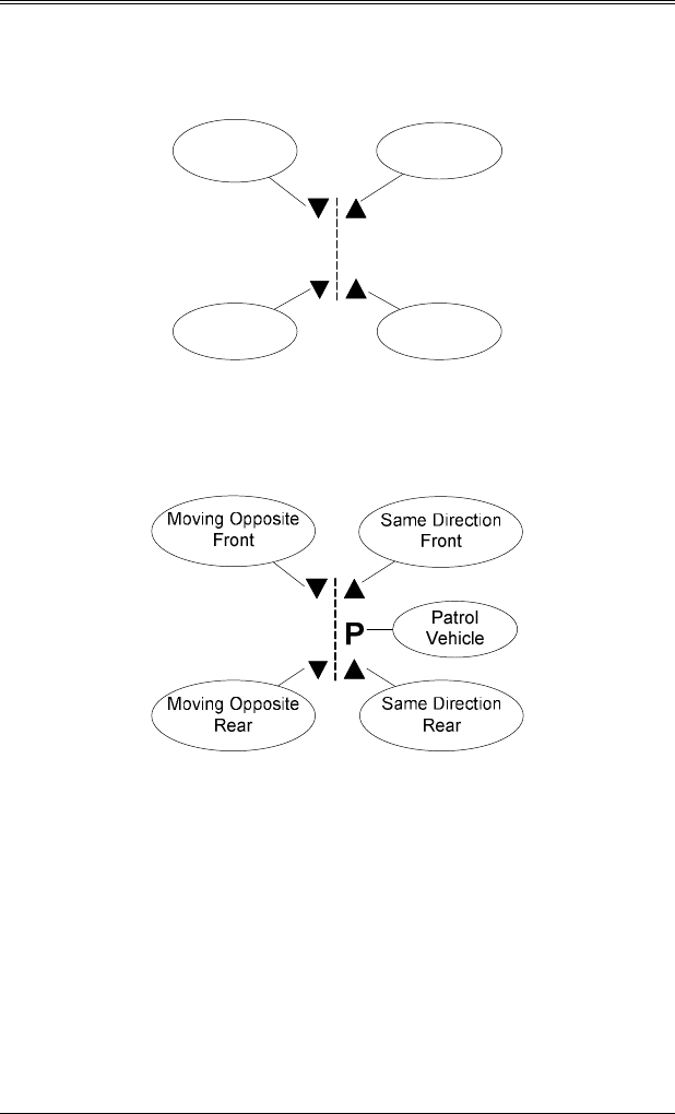
SECTION 13—DIRECTIONAL SUPPLEMENT
13.2
13.1 STATIONARY ROAD GRAPHIC
Front
Receding
Front
Approaching
Rear
Approaching
Rear
Receding
13.2 MOVING MODE ROAD GRAPHIC
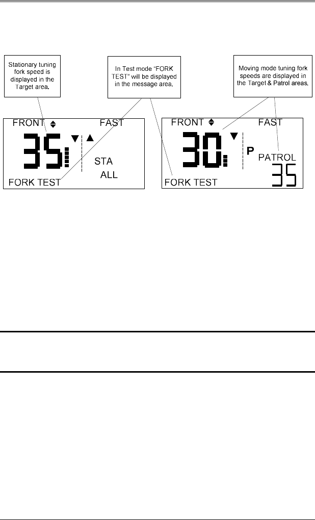
SECTION 13—DIRECTIONAL SUPPLEMENT
13.3
13.3 TEST MODE
Pressing the Test (√) switch places the radar in
test
mode,
which is indicated by the “FORK TEST” displayed in the
message area. While in test mode, the radar will display all
speeds, both moving targets and non-moving targets such
as tuning forks. The unit will remain in test mode for 30
seconds. Selecting a new mode, such as changing from
stationary to moving, will refresh the timeout to 30 seconds
allowing fork testing of all modes.
NOTE: Pressing the test button while in test mode will
turn off test mode immediately.
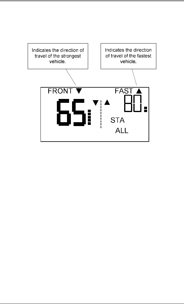
SECTION 13—DIRECTIONAL SUPPLEMENT
13.4
13.4 STATIONARY OPERATION
13.4.1 STATIONARY ALL
To monitor traffic in both directions (the Raptor RP-1 will
automatically indicate which direction the strongest and
fastest vehicles are traveling); repeatedly depress the
MODE switch until “STA ALL” is displayed in the Patrol
area.
When the radar is operated in the Stationary “ALL” mode,
the roadway graphic will display both approaching and
receding indicators. When a target is detected, the
appropriate direction indicator (approaching or receding)
will be displayed above the Target area.
If the “Fastest” function is activated, the appropriate fastest
directional indicator (approaching or receding) will be
displayed above the Fastest Target area.
The example shown is for an approaching 65 mph strongest
vehicle and a receding 80 mph fastest vehicle.
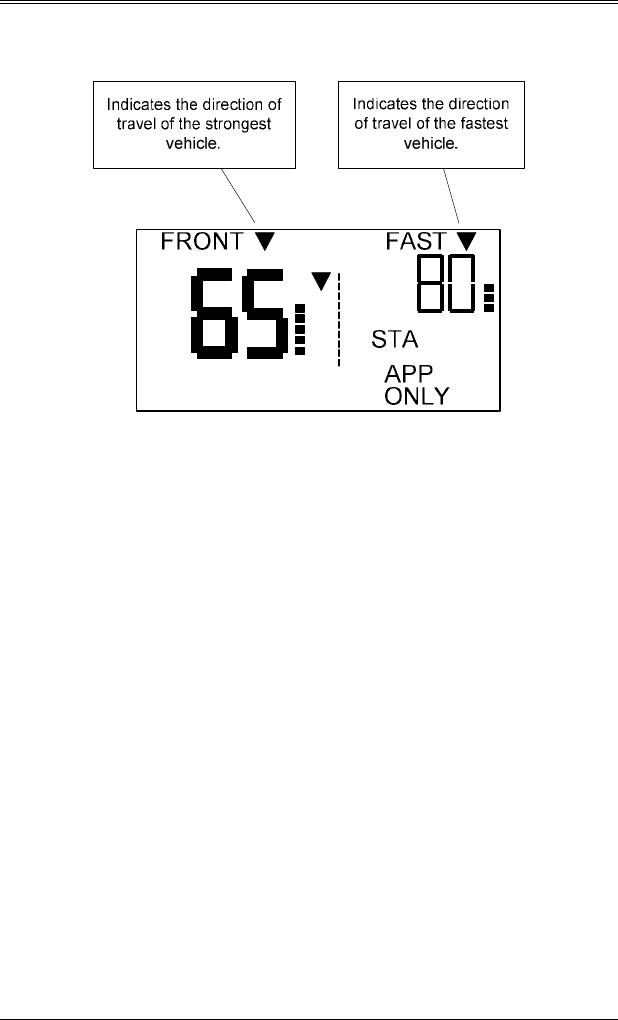
SECTION 13—DIRECTIONAL SUPPLEMENT
13.5
13.4.2 STATIONARY APPROACHING ONLY
To activate the stationary, approaching targets only mode,
repeatedly depress the MODE switch until “STA APR
ONLY” appears in the Patrol area. All receding targets
will be ignored in this mode.
When the radar is operated in the Stationary Approaching
Only mode, the Target area will indicate the strongest
approaching target speed. The road graphic indicator for
approaching vehicles will be on.
If the “Fastest” function is activated, the Fastest Target area
will display the fastest approaching target speed.
The example shown is for an approaching 65 mph strongest
vehicle and an approaching 80 mph fastest vehicle.
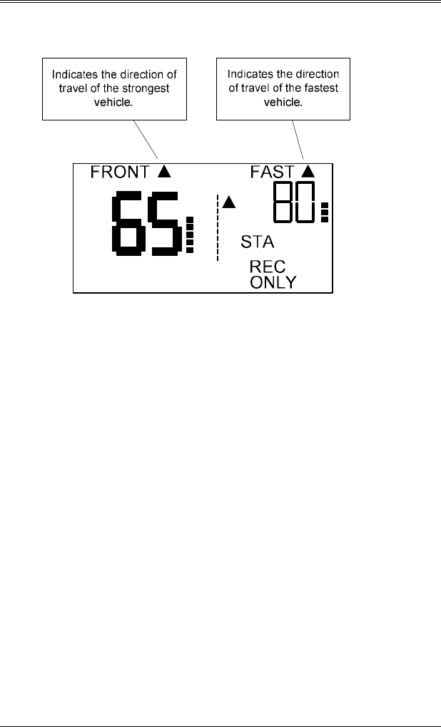
SECTION 13—DIRECTIONAL SUPPLEMENT
13.6
13.4.3 STATIONARY RECEDING ONLY
To activate the stationary, receding targets only mode,
repeatedly depress the MODE switch until “STA REC
ONLY” appears in the Patrol area. All approaching targets
will be ignored in this mode.
When the radar is operated in the Stationary Receding Only
mode, the Target area will indicate the strongest receding
target speed. The road graphic indicator for receding
vehicles will be on.
If the “Fastest” function is activated, the Fastest Target area
will display the fastest receding target speed.
The example shown is for a receding 65 mph strongest
vehicle and a receding 80 mph fastest vehicle.
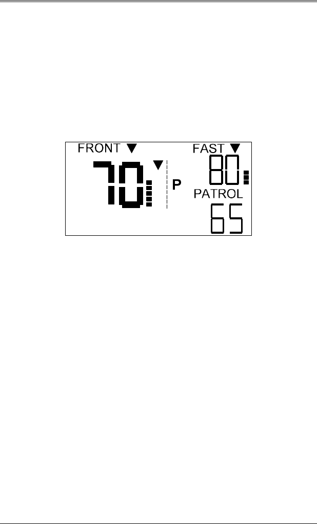
SECTION 13—DIRECTIONAL SUPPLEMENT
13.7
13.5 MOVING MODE OPERATION
Patrol Speed:
In all moving mode operations the PATROL window
indicates the speed of the patrol vehicle and the patrol road
graphic indicator will be lit.
13.5.2 MOVING OPPOSITE
When operating the radar in Moving Opposite mode, the
patrol vehicle and moving opposite road graphic will be on.
The strongest vehicle speed will be displayed in the Target
area.
If the “Fastest” function is activated, the Fastest Target area
will display the fastest moving opposite target speed.
The example shown is for a patrol vehicle speed of 65 mph,
a moving opposite 70 mph strongest vehicle, and a moving
opposite 80 mph fastest vehicle.
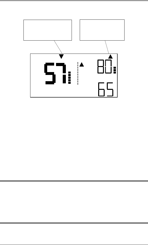
SECTION 13—DIRECTIONAL SUPPLEMENT
13.8
13.5.2 MOVING SAME-DIRECTION
FRONT FAST
PATROL
P
Indicates the direction of
travel of the strongest
vehicle.
Indicates the direction
of travel of the fastest
vehicle.
When operating the radar in Same-Direction mode, the
patrol vehicle and same direction road graphic indicators
will be on. The strongest vehicle speed will be displayed in
the Target speed area. When a target is detected, the
appropriate direction indicator (approaching or receding)
will be displayed above the Target area
If the “Fastest” function is activated, the Fastest Target area
will display the fastest moving same direction target speed.
When a fastest target is detected, the appropriate fastest
directional indicator (approaching or receding) will be
displayed above the Fastest Target area
NOTE: The Raptor RP-1 does not require any input from
the operator in Same Direction mode. The unit
will automatically detect if the target vehicle is
slower than the patrol vehicle and subtract the
separation speed to always provide the operator
the correct speed.

SECTION 13—DIRECTIONAL SUPPLEMENT
13.9
NOTE:
In the Same-Direction Fastest Mode, the “fastest”
target vehicle must be faster than the patrol vehicle
by 3 MPH. EXAMPLE 1: Patrol vehicle = 65
MPH. Large target (strongest) = 43 MPH. Fastest
vehicle = 56. In this event, no fastest speed would
be displayed since the faster vehicle is SLOWER
than the patrol vehicle.
EXAMPLE 2: Patrol vehicle = 65. Large target =
43 MPH. Fastest vehicle = 78 MPH. The
PATROL window will display 65, the TARGET
window will display 43 and the FAST window will
display 78.
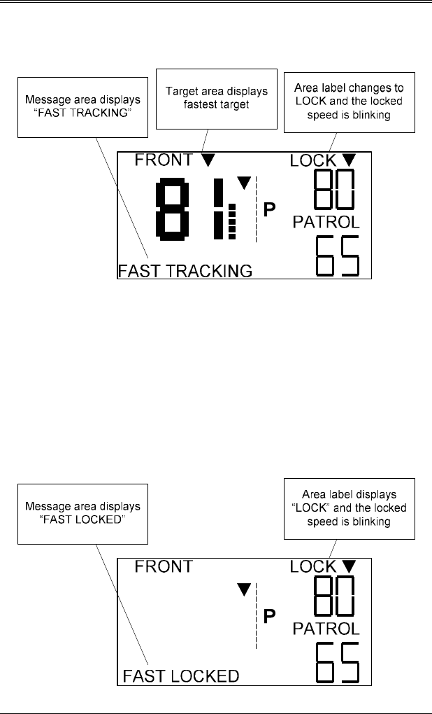
SECTION 13—DIRECTIONAL SUPPLEMENT
13.10
13.6 FASTEST LOCKING
If the Lock button is pressed while tracking a fastest
vehicle in any mode, the fastest speed will be locked and
blinked in the Lock area, and fastest tracking will move to
the Target area. The Message will display “FAST
TRACKING” to alert the user the speed in the Target area
is from the fastest target speed.
If there is no longer a vehicle to track after lock, the
Message area will display “FAST LOCKED” to alert the
user the current lock was made on a fastest target.

SECTION 14--WARRANTY
14.1
14. WARRANTY
The Kustom Signals
Traffic Safety Radar
system is guaranteed
to be free of defects in materials and workmanship for a period
of two (2) years from date of delivery to the Owner or Lessee.
•
This Warranty applies only to the original registered
Owner or Lessee on file at Kustom Signals, Inc., and
cannot be assigned or transferred to a third party.
•
The Owner or Lessee shall use the Equipment in
accordance with the manufacturer’s operational
instructions.
•
The Owner’s or Lessee’s exclusive remedy under this
Warranty is limited to repair to the manufacturer’s
operational specifications or replacement, at the sole
discretion of Kustom Signals, Inc. or its agent, of the
Equipment as (i) is covered by this Warranty; (ii) is
delivered to Kustom Signals, Inc. or its agent at the
Owner’s or Lessee’s expense within the term of this
Warranty; and (iii) upon examination thereof discloses
to the exclusive satisfaction of Kustom Signals, Inc. or
its agent to have been defective in material or
workmanship. Warranty service and repairs must be
performed by an Authorized Kustom Signals Warranty
Service Center or the Factory Customer Service Center
or this Warranty is void.
•
Failure of the Owner or Lessee to observe any
conditions set forth in this warranty; or equipment
damage arising from flood, fire, vehicle collision, act of
God or similar event or catastrophe; or tampering,
abuse, or misuse of the equipment by Owner, Lessee or
third party will render the Owner or Lessee responsible
for the cost of bringing the system within the
manufacturer’s operational specifications.

SECTION 14--WARRANTY
14.2
•
This warranty is not intended to supplant normal care
and service by the Owner or Lessee, as specified in the
Operator’s Manual, and shall not apply to equipment
that has been defaced or damaged through normal
usage.
•
The liability of Kustom Signals, Inc., if any, with
respect to the equipment, shall be limited as provided in
this Warranty. Kustom Signals, Inc. disclaims any
obligation or liability for the loss of use of the
Equipment warranted, loss of time, inconvenience,
commercial loss or other direct, consequential, special
or incidental damages. Kustom Signals, Inc. makes no
warranties of any kind other than as herein expressly
provided, expressed or implied, and specifically
disclaims the implied warranties of merchantability and
of fitness for a particular purpose. You may have
additional rights under this Warranty that vary from
state to state.
•
No action for breach of this warranty may be
commenced more than one year after the date of alleged
breach.
EQUIPMENT SUPPLIED WITH CONSUMABLE
ITEMS
Items such as tires, non-rechargeable batteries, light bulbs,
transmitter carrying pouches, and microphone cables
w/microphone and windscreen are considered consumable
items and as such are not covered by this warranty.
SMART RADAR
SMART system radar units are warranted for two years,
subject to the warranty terms listed above.
AIRBAG CAUTION
Equipment mounted in 1994 or later series police
Equipment mounted in 1994 or later series police Equipment mounted in 1994 or later series police
Equipment mounted in 1994 or later series police
vehicles may interfere with the operation of
vehicles may interfere with the operation of vehicles may interfere with the operation of
vehicles may interfere with the operation of
passenger side airbags. Information is available
passenger side airbags. Information is available passenger side airbags. Information is available
passenger side airbags. Information is available
directly fr
directly frdirectly fr
directly from the automobile manufacturers
om the automobile manufacturers om the automobile manufacturers
om the automobile manufacturers
regarding areas for safe mounting of equipment
regarding areas for safe mounting of equipment regarding areas for safe mounting of equipment
regarding areas for safe mounting of equipment
such as police radar.
such as police radar.such as police radar.
such as police radar.
Since this information will vary by vehicle make
Since this information will vary by vehicle make Since this information will vary by vehicle make
Since this information will vary by vehicle make
and model year, Kustom Signals recommends
and model year, Kustom Signals recommends and model year, Kustom Signals recommends
and model year, Kustom Signals recommends
contacting the vehicle manufacturer and following
contacting the vehicle manufacturer and following contacting the vehicle manufacturer and following
contacting the vehicle manufacturer and following
their instruc
their instructheir instruc
their instructions with respect to mounting of radar
tions with respect to mounting of radar tions with respect to mounting of radar
tions with respect to mounting of radar
units and other equipment.
units and other equipment.units and other equipment.
units and other equipment.
For additional mounting suggestions, please contact
For additional mounting suggestions, please contact For additional mounting suggestions, please contact
For additional mounting suggestions, please contact
the Kustom Signals Customer Service Department.
the Kustom Signals Customer Service Department.the Kustom Signals Customer Service Department.
the Kustom Signals Customer Service Department.
Kustom Signals cannot accept any liability for
Kustom Signals cannot accept any liability for Kustom Signals cannot accept any liability for
Kustom Signals cannot accept any liability for
equipment, which has been mounted in con
equipment, which has been mounted in conequipment, which has been mounted in con
equipment, which has been mounted in conflict with
flict with flict with
flict with
the vehicle manufacturer's recommendation for
the vehicle manufacturer's recommendation for the vehicle manufacturer's recommendation for
the vehicle manufacturer's recommendation for
proper airbag deployment.
proper airbag deployment.proper airbag deployment.
proper airbag deployment.

PRINTER’S NOTES
1. Print Airbag Caution Sheet (located at back of manual) on green bond and insert
between pages 3.6 and 4.1 in the manual.
2. Print Section A—Printer / DataLogger Optional Features (front and back) on Buff
bond and insert between warranty section and radar log.
DO NOT INCLUDE
THIS SHEET AS
PART OF THE
MANUAL.

UNIT SERIAL NUMBER
_____________
ON DUTY TEST OFF DUTY TEST
DATE TEST
FORK/
READ
DRIVE/
RADAR
SIGN TEST
FORK/
READ
DRIVE/
RADAR
SIGN COMMENTS