Kyocera KM 1820 KM1820_SSG_ENG User Manual To The A4287ff3 171c 4657 8f7f E2b6efa8a9d3
User Manual: Kyocera KM-1820 to the manual
Open the PDF directly: View PDF ![]() .
.
Page Count: 34
- About this Guide
- Trademark Information
- Legal Restrictions on Scanning
- Getting connected
- Contents
- 1 Preparations
- 2 Setup
- 3 Operation

Network Scanner Setup Guide
KM-1820
FS-1118MFP
The KM-1820 model is applicable to USA, Canada, and the Asia Pacific region.
The FS-1118MFP model is applicable to Europe and Australasia.

NETWORK SCANNER SETUP GUIDE i
Introduction
About this Guide
This guide contains instructions on the initial setup of the scanner functions and the
basic procedures for using this machine as a network scanner.
Trademark Information
• Microsoft, Windows, Windows NT and Internet Explorer are registered
trademarks of Microsoft Corporation of America and other countries.
• Windows Me, Windows Server and Windows XP are trademarks of Microsoft
Corporation.
• Ethernet is a registered trademark of Xerox Corporation.
• IBM and IBM PC/AT are trademarks of International Business Machines
Corporation of America.
• Adobe and Acrobat are registered trademarks of Adobe Systems Incorporated.
All other company and product names contained in this guide are trademarks or
registered trademarks of their respective companies. The designations ™ and ® will
not be used in this guide.
Legal Restrictions on Scanning
IMPORTANT: Scanning legally copyrighted materials, such as documents, musical
scores, pictures, woodblock prints, maps, drawings and photographs, for any intent
other than your own personal or home use, or other such purpose, is prohibited
under the copyright law without prior permission from the legal copyright owner.
Scanning the following items may result in legal penalty:
Bank notes, coins, government-issue securities, national bonds, local bonds, foreign
currencies and securities, unused postage stamps, government post cards,
government stamps, and securities regulated by the liquor tax law.
Other items that you should not scan:
It is additionally recommended that you do not attempt to scan government-issue
passports, licenses, permits, ID cards, securities, commuter tickets, passes, books
of tickets and meal coupons issued by public or private organizations.
Introduction
ii NETWORK SCANNER SETUP GUIDE
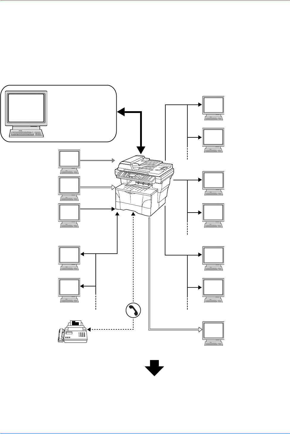
Getting connected
The following procedures are required in order to use this machine as a scanner.
Connect the machine to your PC (Example Connection)
Connecting the scanner to your PC network with a network
cable (100BASE-TX or 10BASE-T) Page 1
Next Page
FAX (Option)
Send FTP
Sends the scanned
image as a data file on
the FTP.
Send E-mail
Sends the image data
of scanned originals to
the desired recipient
as a file attached to an
E-mail message.
Send SMB
Saves the scanned
image as a data file on
your PC.
MFP
FAX
Administrator’s
PC
KYOCERA COMMAND
CENTER
Network settings Scanner
default settings User and
destination registration
Network FAX
(Option)
TWAIN Scanning
TWAIN is a
standardized interface
for communication
between software
applications and
image acquisition
devices. It supports
scanning via the USB
interface.
Parallel
USB
USB
Network
Printing
Network
Network
Network
Network
1
Introduction
NETWORK SCANNER SETUP GUIDE iii
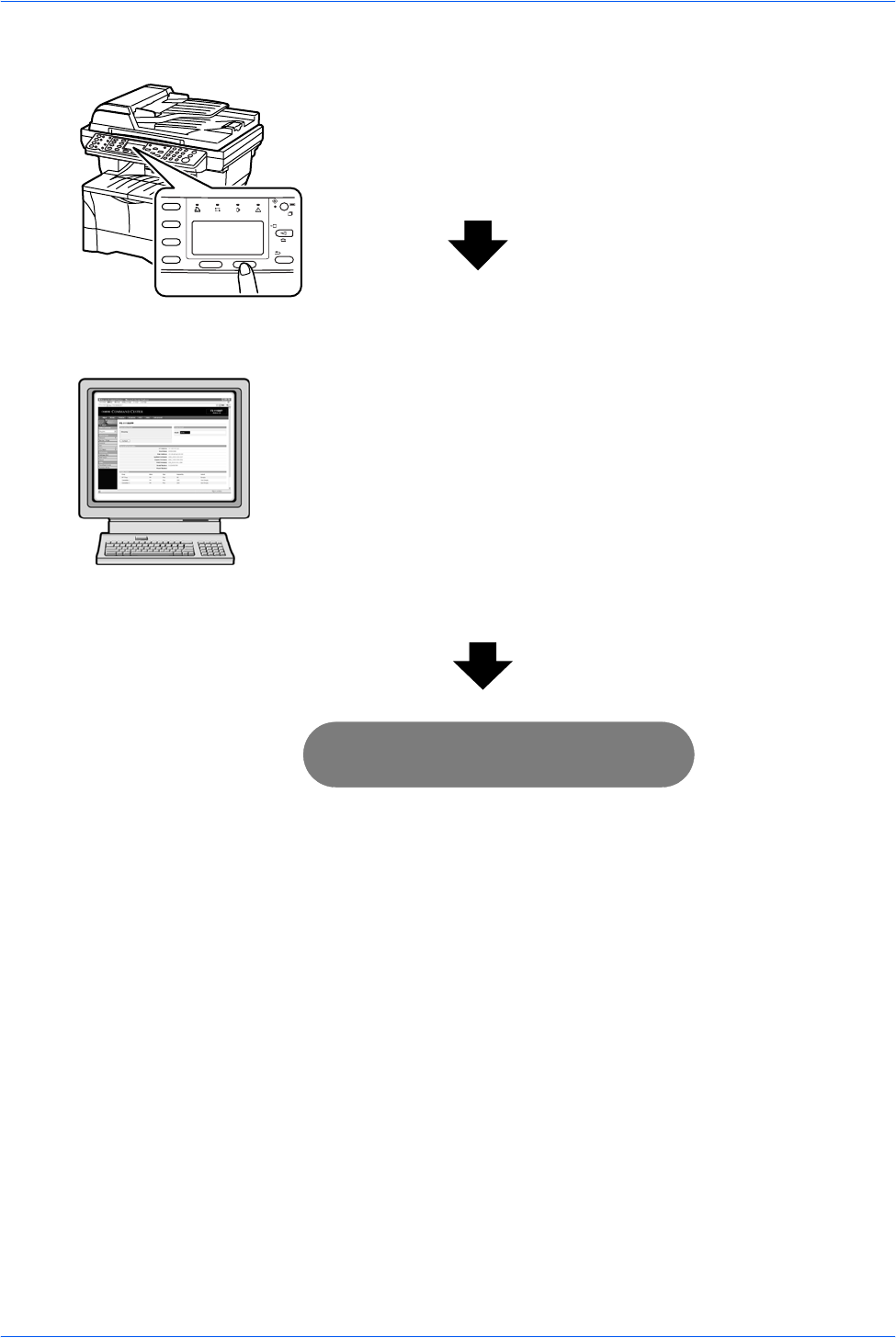
Perform the required operation at the machine
Perform the required operation at the PC
Network settings
(register the IP address, subnet mask, etc.) Page 5
Date and Time settings
(register the time zone, date and time, etc.) Page 3
2
Accessing COMMAND CENTER
(Internal HTML web page)
• Advanced TCP/IP Setting Page 7
• E-mail Setting Page 8
• Enabling SMB Function Page 11
• Enabling FTP Function Page 12
• Registering the Address Book Page 13
• Registering User Login Page 17
Page 7
3
You’re now ready to scan!

Introduction
iv NETWORK SCANNER SETUP GUIDE

NETWORK SCANNER SETUP GUIDE v
Contents
Introduction . . . . . . . . . . . . . . . . . . . . . . . . . . . . . . . . . . . . . . . . . . . . . . . . . . . . . . . . . . . . . . . . . . i
About this Guide . . . . . . . . . . . . . . . . . . . . . . . . . . . . . . . . . . . . . . . . . . . . . . . . . . . . . . . . . . . . . . . i
Trademark Information . . . . . . . . . . . . . . . . . . . . . . . . . . . . . . . . . . . . . . . . . . . . . . . . . . . . . . . . . . i
Legal Restrictions on Scanning. . . . . . . . . . . . . . . . . . . . . . . . . . . . . . . . . . . . . . . . . . . . . . . . . . . . i
Getting connected. . . . . . . . . . . . . . . . . . . . . . . . . . . . . . . . . . . . . . . . . . . . . . . . . . . . . . . . . . . . . . ii
1 Preparations . . . . . . . . . . . . . . . . . . . . . . . . . . . . . . . . . . . . . . . . . . . . . . . . . . . . . . . . . . . . . . . . .1
Connecting the Cables . . . . . . . . . . . . . . . . . . . . . . . . . . . . . . . . . . . . . . . . . . . . . . . . . . . . . . . . . .1
Connecting the Network Cable . . . . . . . . . . . . . . . . . . . . . . . . . . . . . . . . . . . . . . . . . . . . .1
Connecting the Parallel or USB Cable . . . . . . . . . . . . . . . . . . . . . . . . . . . . . . . . . . . . . . . .1
Connecting the Power Cord. . . . . . . . . . . . . . . . . . . . . . . . . . . . . . . . . . . . . . . . . . . . . . . .2
Turning the Machine On . . . . . . . . . . . . . . . . . . . . . . . . . . . . . . . . . . . . . . . . . . . . . . . . . . . . . . . . .2
2 Setup . . . . . . . . . . . . . . . . . . . . . . . . . . . . . . . . . . . . . . . . . . . . . . . . . . . . . . . . . . . . . . . . . . . . . . .3
Date and Time Settings. . . . . . . . . . . . . . . . . . . . . . . . . . . . . . . . . . . . . . . . . . . . . . . . . . . . . . . . . .3
Setting the Time Zone . . . . . . . . . . . . . . . . . . . . . . . . . . . . . . . . . . . . . . . . . . . . . . . . . . . .3
Summer Time Setting. . . . . . . . . . . . . . . . . . . . . . . . . . . . . . . . . . . . . . . . . . . . . . . . . . . . .3
Setting the Current Date and Time. . . . . . . . . . . . . . . . . . . . . . . . . . . . . . . . . . . . . . . . . . .4
Network Settings. . . . . . . . . . . . . . . . . . . . . . . . . . . . . . . . . . . . . . . . . . . . . . . . . . . . . . . . . . . . . . .5
Registering the IP Address . . . . . . . . . . . . . . . . . . . . . . . . . . . . . . . . . . . . . . . . . . . . . . . .5
Registering the Subnet Mask . . . . . . . . . . . . . . . . . . . . . . . . . . . . . . . . . . . . . . . . . . . . . . .6
Registering the Default Gateway . . . . . . . . . . . . . . . . . . . . . . . . . . . . . . . . . . . . . . . . . . . .6
Accessing COMMAND CENTER . . . . . . . . . . . . . . . . . . . . . . . . . . . . . . . . . . . . . . . . . . . . . . . . . .7
Advanced TCP/IP Setting . . . . . . . . . . . . . . . . . . . . . . . . . . . . . . . . . . . . . . . . . . . . . . . . . . . . . . . .7
Advanced > Protocols > TCP/IP > General page. . . . . . . . . . . . . . . . . . . . . . . . . . . . . . . .7
E-mail Setting . . . . . . . . . . . . . . . . . . . . . . . . . . . . . . . . . . . . . . . . . . . . . . . . . . . . . . . . . . . . . . . . .8
Advanced > E-mail > SMTP > General page. . . . . . . . . . . . . . . . . . . . . . . . . . . . . . . . . . .9
Enabling SMB Function. . . . . . . . . . . . . . . . . . . . . . . . . . . . . . . . . . . . . . . . . . . . . . . . . . . . . . . . .11
Scanner > SMB page. . . . . . . . . . . . . . . . . . . . . . . . . . . . . . . . . . . . . . . . . . . . . . . . . . . .11
Enabling FTP Function . . . . . . . . . . . . . . . . . . . . . . . . . . . . . . . . . . . . . . . . . . . . . . . . . . . . . . . . .12
Scanner > FTP page . . . . . . . . . . . . . . . . . . . . . . . . . . . . . . . . . . . . . . . . . . . . . . . . . . . .12
Registering the Address Book. . . . . . . . . . . . . . . . . . . . . . . . . . . . . . . . . . . . . . . . . . . . . . . . . . . .13
Basic > Address Book page. . . . . . . . . . . . . . . . . . . . . . . . . . . . . . . . . . . . . . . . . . . . . . .13
Registering External Address Book . . . . . . . . . . . . . . . . . . . . . . . . . . . . . . . . . . . . . . . . .16
Advanced > Management > LDAP page . . . . . . . . . . . . . . . . . . . . . . . . . . . . . . . . . . . . .16
Registering User Login . . . . . . . . . . . . . . . . . . . . . . . . . . . . . . . . . . . . . . . . . . . . . . . . . . . . . . . . .17
Basic > Security > User Login page. . . . . . . . . . . . . . . . . . . . . . . . . . . . . . . . . . . . . . . . .17
Adding a New User Login . . . . . . . . . . . . . . . . . . . . . . . . . . . . . . . . . . . . . . . . . . . . . . . .18
Editing the User Login . . . . . . . . . . . . . . . . . . . . . . . . . . . . . . . . . . . . . . . . . . . . . . . . . . .18
Deleting the User Login . . . . . . . . . . . . . . . . . . . . . . . . . . . . . . . . . . . . . . . . . . . . . . . . . .18
Entering User Login . . . . . . . . . . . . . . . . . . . . . . . . . . . . . . . . . . . . . . . . . . . . . . . . . . . . .19
3 Operation . . . . . . . . . . . . . . . . . . . . . . . . . . . . . . . . . . . . . . . . . . . . . . . . . . . . . . . . . . . . . . . . . .21
Basic Scanning Procedure . . . . . . . . . . . . . . . . . . . . . . . . . . . . . . . . . . . . . . . . . . . . . . . . . . . . . .21
Function Defaults . . . . . . . . . . . . . . . . . . . . . . . . . . . . . . . . . . . . . . . . . . . . . . . . . . . . . . .24

Contents
vi NETWORK SCANNER SETUP GUIDE
NETWORK SCANNER SETUP GUIDE 1
1 Preparations
Connecting the Cables
The machine can be connected to a network or directly to a PC.
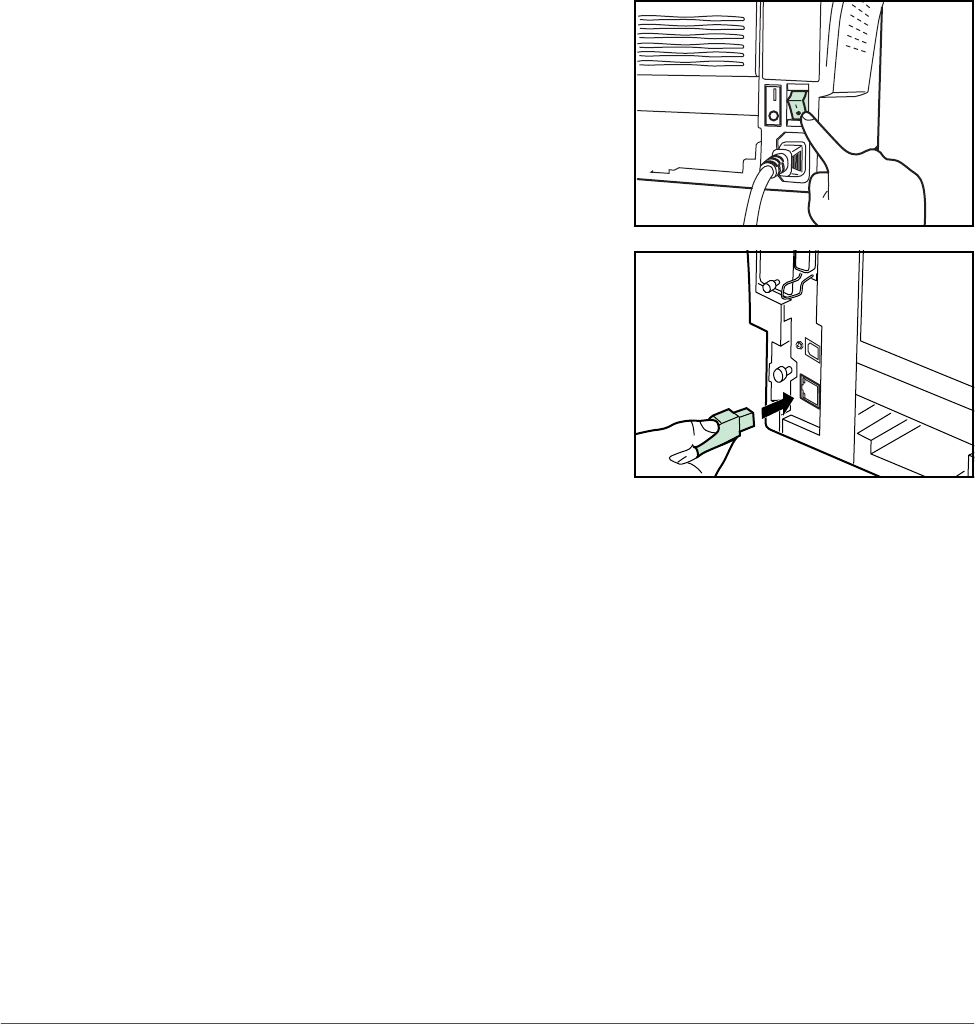
Connecting the Network Cable
When connecting the machine to the network, use the appropriate network cable
(10BASE-T or 100BASE-TX).
1Ensure the machine is off, and remove the
power cord from the outlet.
2Connect the network cable to the network
interface connector at the rear of the
machine.
3Connect the other end of the network cable to your network device.
4Change the appropriate network settings on the operation panel - refer to Network
Settings on page 5.
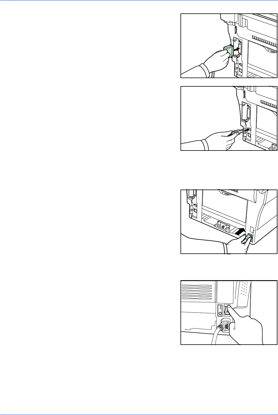
Connecting the Parallel or USB Cable
Before connecting via the USB interface, install the necessary drivers from the
included Product Library CD.
To connect the machine directly to your PC, use either a parallel cable or USB cable.
1Turn the machine off, remove the power cord from the outlet and turn the PC off.
Preparations
2 NETWORK SCANNER SETUP GUIDE
2Connect the printer cable to the appropriate
connector located at the rear of the
machine.
3Connect the other end of the printer cable to the appropriate connector on your PC.
Connecting the Power Cord
Connect the power cord to the rear of the
machine. Connect the other end to a
suitable power outlet.
Turning the Machine On
Turn the power switch on. The machine will
begin to warm up after which the basic
screen is displayed.
Parallel
Cable
USB
Cable

NETWORK SCANNER SETUP GUIDE 3
2Setup
Date and Time Settings
Setting the Time Zone
You can also make this setting using the COMMAND CENTER. For details on
COMMAND CENTER, refer to Accessing COMMAND CENTER on page 7.
1Access Time Zone.
2Press S or T to select the time zone that you are in.
3Press Enter. The message display shows Completed and returns to the Date/
Timer Set. screen.
4Enable Summer Time if needed - refer to Summer Time Setting on page 3.
Summer Time Setting
Follow these instructions to turn the summer (daylight saving) time setting on and off.
NOTE: This setting is valid only in areas where summer time is observed.
1Press S or T to select Summer Time.
2Press Enter.
3Press S or T to select either On or Off.
4Press Enter. The message display shows Completed and returns to the Date/
Timer Set. screen.
5Enter the Date and Time - refer to Setting the Current Date and Time on page
4.
System Menu/
Counter
S or T
Date/Timer Set
Enter
S or T
Time Zone
Enter

Setup
4 NETWORK SCANNER SETUP GUIDE
Setting the Current Date and Time
You can also make this setting using COMMAND CENTER.
NOTE: Periodically check the time that is shown in the message display and adjust
as necessary to match the current time.
1Press S or T to select Year/Time.
2Press Enter. The date setting screen (year:month:day) is displayed.
3To set the date, for each field press S or T as many times as necessary to
display the correct value, then press X to move to the next field.
4When the date is correct, press Enter. The time setting screen
(hour:minute:second) is displayed.
5To set the time, for each field press S or T as many times as necessary to
display the correct value then press X to move to the next field.
6Press Enter. The message display shows Completed and returns to the Date/
Timer Set. screen.
7Press right Select. The message display returns to the basic screen.

Setup
NETWORK SCANNER SETUP GUIDE 5
Network Settings
Registering the IP Address
Check the IP address with your network administrator before changing this setting.
You can enter an IP address only when the DHCP setting is Off and the TCP/IP
setting is On. Any changes made to the network settings will only become effective
after you turn the machine off and then back on again.
1Access IP Address.
2Use the numeric keys to enter each segment of the IP address in turn,
pressing X or [*.] to move between segments.
If you make an error in entering a portion of the IP address, press W to
return to the previous block of digits and re-enter the correct number.
3Press Enter on completion.
4Register the Subnet Mask - refer to Registering the Subnet Mask on page 6.
System Menu/
Counter
S or T
System Setting
Enter
S or T
Network Setting
Enter
S or T
TCP/IP Setting
Enter
S or T
DHCP
Enter
S or T
Off
Enter
S or T
IP Address
Enter

Setup
6 NETWORK SCANNER SETUP GUIDE
Registering the Subnet Mask
1Press S or T to select Subnet Mask.
2Press Enter.
3Use the numeric keys to enter each segment of the Subnet Mask in turn,
pressing X or [*.] to move between segments.
If you make an error in entering a portion of the Subnet Mask, press W to
return to the previous block of digits and re-enter the correct number.
4Press Enter on completion.
5Register the Default Gateway - refer to Registering the Default Gateway on
page 6.
Registering the Default Gateway
1Press S or T to select Default Gateway.
2Press Enter.
3Use the numeric keys to enter each segment of the Default Gateway in turn,
pressing X or [*.] to move between segments.
If you make an error in entering a portion of the Default Gateway, press W
to return to the previous block of digits and re-enter the correct number.
4Press Enter on completion.
5When you have changed all the network settings, press right Select. The
message display returns to the basic screen.
Setup
NETWORK SCANNER SETUP GUIDE 7
Accessing COMMAND CENTER
COMMAND CENTER refers to the machine’s integrated web-based interface. This
enables you to verify the operating status of the machine and change settings related
to security, network printing, e-mail transmission and advanced networking.
1Open the web browser.
2In the Address or Location bar, enter the machine’s IP address as the URL, e.g.
http://192.168.48.21/. The web page displays basic information about the machine
and COMMAND CENTER as well as the current status of the machine.
3Select a category from the navigation bar on the left to view and set values for that
particular category.
4If administrator privileges have been enabled on the COMMAND CENTER,
remember to enter the correct user name and password when trying to access the
relevant screens.
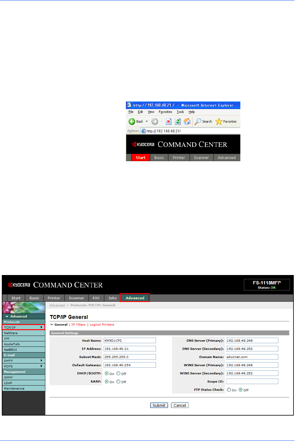
Advanced TCP/IP Setting
Advanced > Protocols > TCP/IP > General page
This page allows you to edit the settings that are required for network printing and
sending e-mail. Restart the machine to register any changed settings.

Setup
8 NETWORK SCANNER SETUP GUIDE
The table below lists the settings displayed on the TCP/IP General Settings page.
E-mail Setting
The following procedure explains the method for attaching scanned data to an e-mail
for transmission.
Scan to e-mail works within the following environments:
• It must have a network environment in which this machine can connect to a
mail server. It is recommended that the machine be used in an environment in
which it can connect to the mail server at any time over a LAN.
• The SMTP settings must be completed. Use COMMAND CENTER to register
the IP address and the host name of the SMTP server.
• There may be times when transmission is not possible due to the size of each
e-mail item.
Item Description
Host Name Specifies a name for the machine system network component. This name is also
used as the NetBEUI Printer Name and the SNMP sysName object.
IP Address Assigns the Internet Protocol address on the machine system network
component. The format of the IP Address is four-byte (32-bit) numbers separated
by dots, e.g. 192.168.48.21.
Subnet Mask Specifies the subnet mask configured on the machine system network
component. If the machine system does not automatically assign a usable
default value and the first number in the IP address is from 192 to 254, then use
255.255.255.0 as the subnet mask.
Default Gateway The IP address of the gateway router for the local network.
DHCP/BOOTP Identifies how the machine obtains its IP configuration: DHCP/BOOTP: automatic
configuration via a BOOTP server or a DHCP server.
RARP Automatic configuration using the Reverse Address Resolution Protocol.
DNS Server (Primary,
Secondary) The IP address of the primary and secondary Domain Name System (DNS)
servers.
Domain Name The Domain Name System (DNS) to which the machine system belongs, such as
abcdnet.com. It should not include the host machine name.
WINS Server (Primary,
Secondary) The IP address of the primary and secondary Windows Internet Name Service
(WINS) servers.
Scope ID This section determines the scope of IP addresses that a Windows server can
grant or lease to any requesting network component. A DHCP server processes
the machine system’s discovery broadcasts and returns an IP address to it. The
DHCP server may be set up to grant an IP address for a limited time (a
temporary lease) or for an unlimited time (an unlimited lease), or it may be
configured with a permanent address reservation for the machine system.
FTP Status Check Enables or disables the FTP Status Check.
Setup
NETWORK SCANNER SETUP GUIDE 9
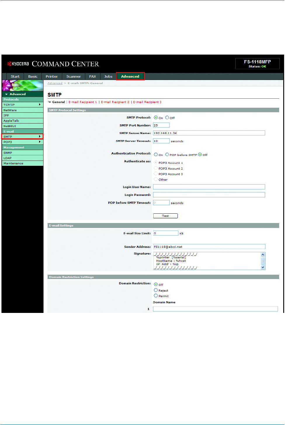
Advanced > E-mail > SMTP > General page
The scanner system network component offers e-mail functionality. SMTP is an
embedded protocol to support this function. To use the e-mail function, the scanner
system should be connected to an e-mail server using the POP3 protocol.

Setup
10 NETWORK SCANNER SETUP GUIDE
The table below lists the settings displayed on the SMTP Protocol Settings page.
Item Description
SMTP Protocol Enables or disables SMTP protocol. To use e-mail, this protocol must be enabled.
SMTP Port Number Set the SMTP Port Number or use the SMTP default port 25.
SMTP Server Name Enter the SMTP server name or its IP address. The maximum length of the SMTP
server name and IP address is 62 characters. If entering the name, a DNS server
address must also be configured. The DNS server address may be entered on
the TCP/IP General tab.
SMTP Server Timeout Enter the default time out for the server in seconds.
Authentication
Protocol Enables or disables the SMTP authentication protocol or sets POP before SMTP
as the protocol. The SMTP authentication supports Microsoft Exchange 2000.
Authenticate as Authentication can be set from three POP3 accounts or you can choose a
different account.
Login Account Name When Other is selected for Authenticate, the account name set here will be used
for SMTP authentication. The maximum length of the login account name is 62
characters.
Login Password When Other is selected for Authenticate, the password set here will be used for
authentication. The maximum length of the login password is 62 characters.
POP before SMTP
Timeout Enter the timeout (in seconds) if you chose POP before SMTP as the
Authentication Protocol.
Test This will test if the SMTP connection can be successfully established.
E-mail Size Limit Enter the maximum size of e-mail that can be sent in kilobytes. When the value is
0, the limitation for e-mail size is disabled.
Sender Address Enter the e-mail address of the person responsible for the scanner system, such
as the machine administrator, so that a reply or non-delivery report will go to a
person rather than to the machine. The sender address must be entered correctly
for SMTP authentication. The maximum length of the sender address is 126
characters.
Signature Enter the signature. The signature is free form text that will appear at the end of
the e-mail body. It is often used for further identification of the machine. The
maximum length of the signature is 126 characters.
Domain Restrictions Enter the domain names that can be permitted or rejected. The maximum length
of the domain name is 30 characters. You can also specify e-mail addresses.
Setup
NETWORK SCANNER SETUP GUIDE 11
Enabling SMB Function
The SMB function enables scanned images to be stored as individual files in a folder
on your PC.
The SMB parameters can be set through the COMMAND CENTER.
The following information about each server needs to be registered on this machine.
• Login user name (using operation panel)
• Password (using operation panel)
• Host name or IP address of the PC
• Port number
• Path (path from the home directory of the PC to the folder for storage)
• Shares the destination's PC folder
Login username and Login password are identical to the Windows User logon on the
PC from which the accessed folder is stored. User access rights for the machine to
the necessary folder should be registered within Windows on that PC.
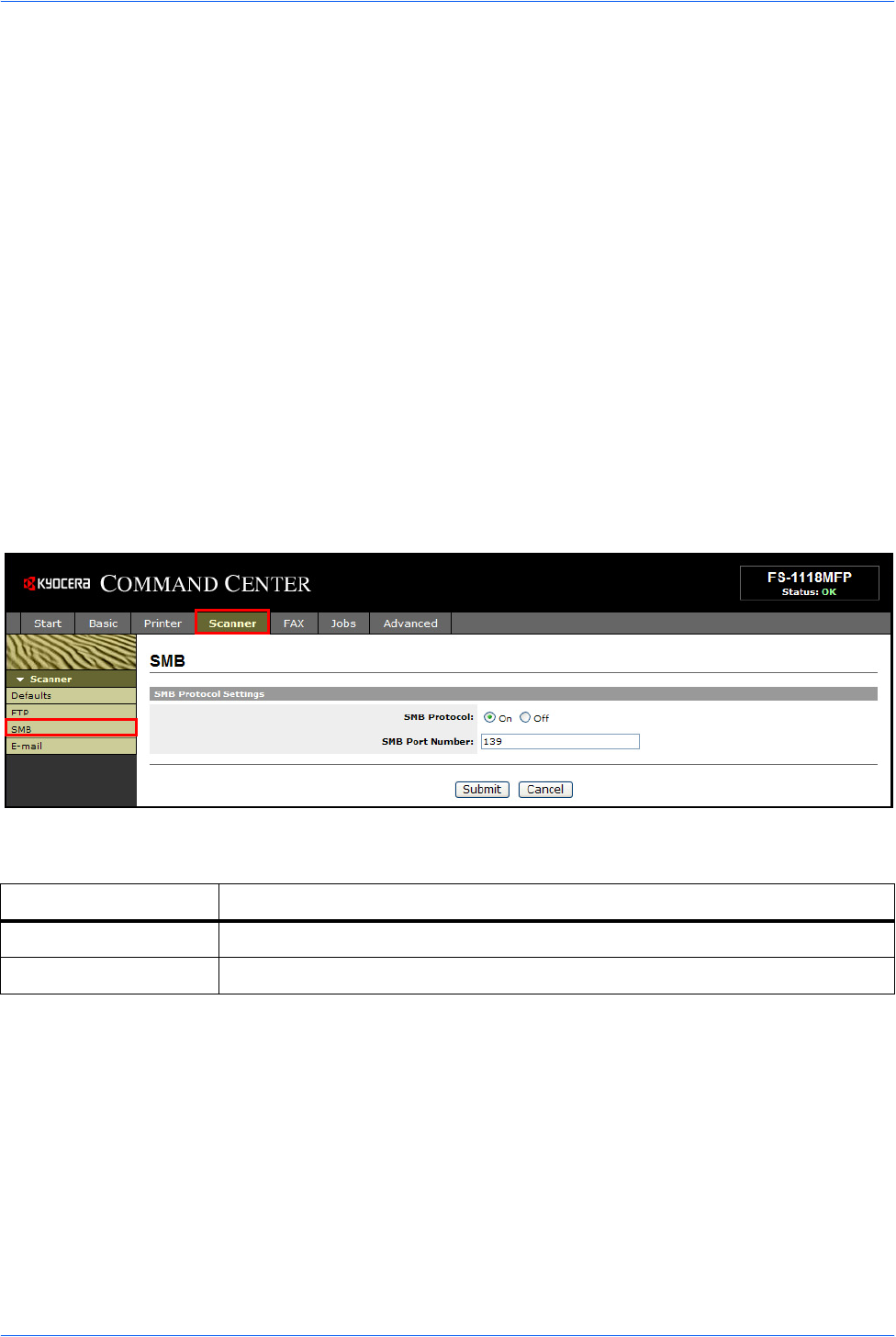
Scanner > SMB page
The table below lists the settings displayed on the scanner SMB page.
Item Description
SMB Protocol Switches the SMB Protocol on or off.
SMB Port Number You can enter the port number to be used by SMB.
Setup
12 NETWORK SCANNER SETUP GUIDE
Enabling FTP Function
The FTP transmission function converts the data of originals scanned on this
machine to the PDF, TIFF, or JPEG format and uploads it directly to an FTP server.
The FTP parameters can be set through the COMMAND CENTER.
The following information is required about each server in order to register them on
this machine. If you are unsure about this information, seek help from the server
administrator.
• Login user name (using operation panel)
• Password (using operation panel)
• Host name or IP address of FTP server
• Port number (normally 21)
• Path (path from the home directory of the FTP server to the folder for storage)
• Shares the FTP server
Login username and Login password are identical to the FTP User login. The FTP
user account for the machine needs to be installed and administrated at the FTP
server.
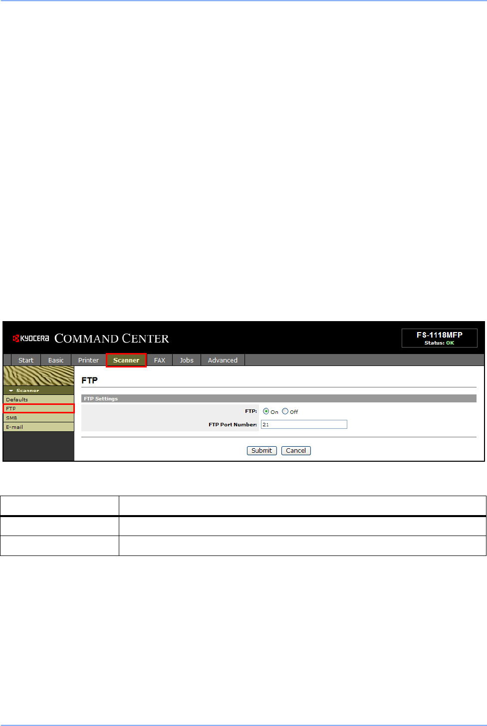
Scanner > FTP page
The table below lists the settings displayed on the scanner FTP page.
Item Description
FTP Switches FTP on or off.
FTP Port Number You can enter the port number to be used by FTP.
Setup
NETWORK SCANNER SETUP GUIDE 13
Registering the Address Book
This machine has an address book function. When an e-mail address, the path to a
PC folder (SMB), FTP server's path, and FAX number are registered in the address
book, it can transmit directly from the operation panel.
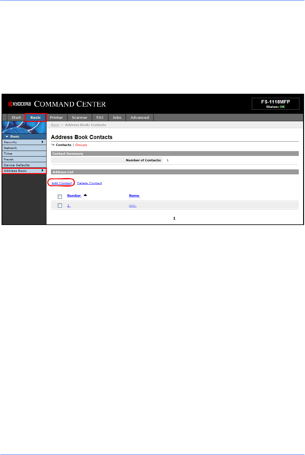
Basic > Address Book page
The Address Book page allows you to add, edit or delete Contacts or Groups.
Setup
14 NETWORK SCANNER SETUP GUIDE
Adding a New Contact
1Open the Address Book Contacts page.
2Click Add Contact and enter the information for the contact. You can specify a fax
number even if the FAX System is not installed.
3Click Submit.

Setup
NETWORK SCANNER SETUP GUIDE 15
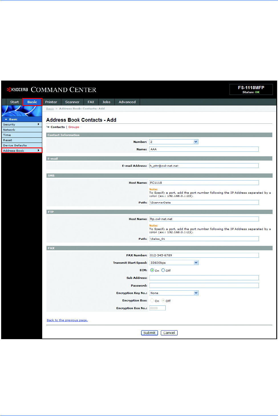
The table below lists the settings displayed on the Address Book Contacts Add page.
Editing a Contact
1Open the Address Book Contacts page.
2Click the Number or Name of the contact.
3Modify the information of the contact.
4Click Submit.
Adding a New Group
1Open the Address Book Groups page.
2Click Add Group and enter the information of the user to be used for the User Login.
3Enter the number and name of the group.
4Click Submit.
Item Description
Number Select the number of this address book.
Name Enter the registration name.
E-Mail Address Enter the e-mail address.
Host Name Enter the PC (FTP server) name or IP address of PC (FTP server).
Path Enter the path of the required folder for uploading data. For example, to store
data in the ScannerData folder in the home directory, enter \ScannerData.
If nothing is entered, data is stored in the home directory.
FAX Number Enter the recipient’s fax number.
Transmit Start Speed Selects the initial fax transmission speed.
ECM Switches the ECM communication on or off.
Sub Address Enter the subaddress for subaddress confidential communication.
Password Enter the password for subaddress confidential communication.
Encryption Key No. Selects the encryption key number to use in the encrypted communication.
Encryption Box Switches the encryption box on or off to register the fax’s encryption box
information.
Encryption Box No. Enter the encryption box number.
Setup
16 NETWORK SCANNER SETUP GUIDE
Editing the Group
1Open the Address Book Groups page.
2Click the number or name of the group to be edited.
3Click Add Members to add the contacts to the group or click Delete Members to
delete the contacts from the group. You can only add one SMB or FTP address to
a group.
4Click Submit.
Registering External Address Book
This machine can refer to an address book on the LDAP server as an external
address book and assign a fax number and e-mail address to the destination.
To use the external address book:
1Register an address book on the LDAP server. For details, refer to the Windows
help.
2Enable LDAP parameters in COMMAND CENTER.
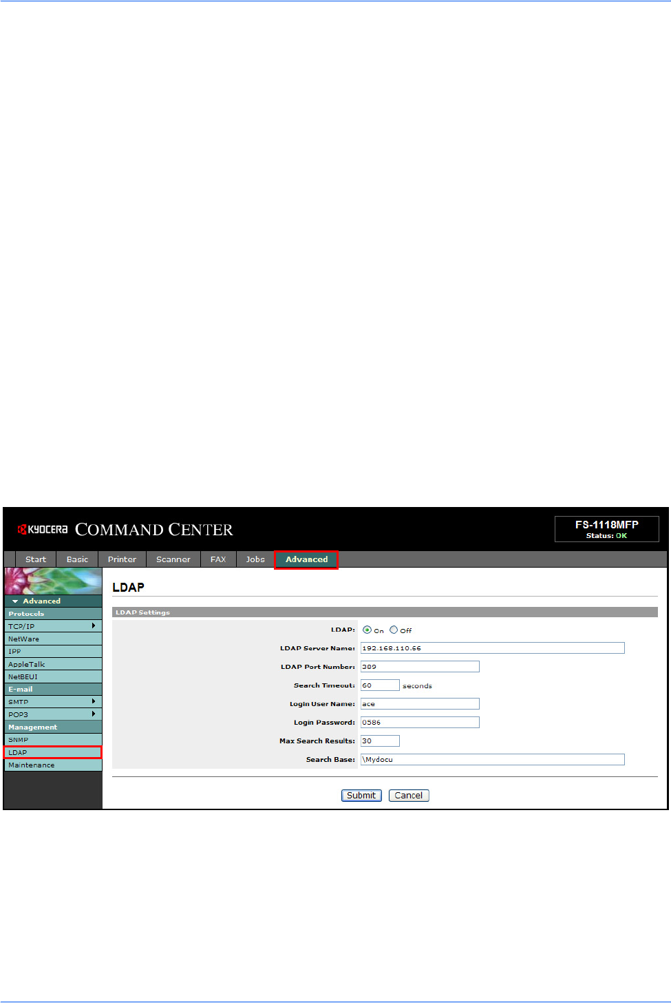
Advanced > Management > LDAP page
Setup
NETWORK SCANNER SETUP GUIDE 17
The table below lists the settings displayed on the LDAP page.
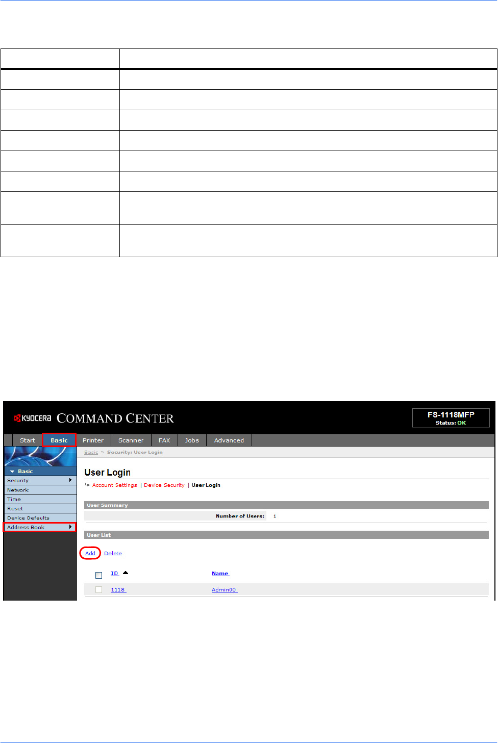
Registering User Login
If the administrator has enabled the User Login function, you will need to enter your
User ID and password in order to use the machine. The factory default User ID and
Password is 1118.
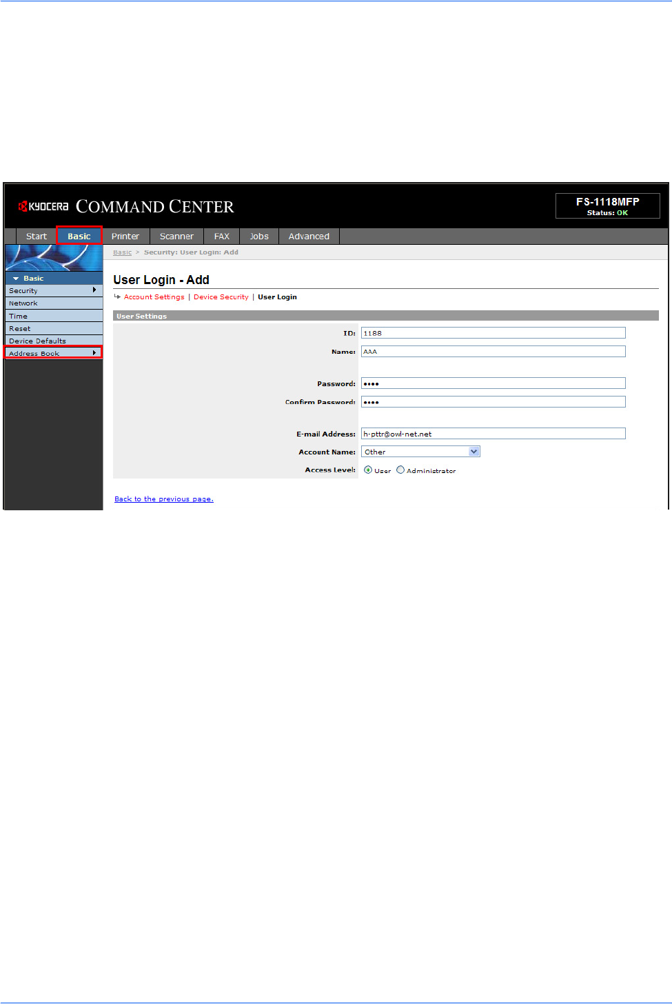
Basic > Security > User Login page
This page lets you add, edit or remove User Logins.
Item Description
LDAP Enables or disables access to the LDAP server.
LDAP Server Name Specifies a name or IP address for the LDAP server.
LDAP Port Number Specifies a port number for LDAP or use the LADP default port 389.
Search Timeout Specifies a period of time for searching the LDAP server.
Login User Name Specifies the user name to login to the LDAP server.
Login Password Specifies the password to login to the LDAP server.
Max Search Results Specifies a maximum number of displayed results which have been searched on
the LDAP address book.
Search Base Specifies a base object which indicates the starting point in the tree structure of
the database for the LDAP directory searching.
Setup
18 NETWORK SCANNER SETUP GUIDE
Adding a New User Login
1Open the User Login page.
2Click Add and enter the information of the user needed for the User Login.
3Click Submit.
Editing the User Login
1Open the User Login page.
2Click the desired number or name to edit the user and modify their information.
3Click Submit.
Deleting the User Login
1Open the User Login page.
2Check the desired user. If you check ID, all users will be checked.
3Click Delete.
4Click Delete.
Setup
NETWORK SCANNER SETUP GUIDE 19
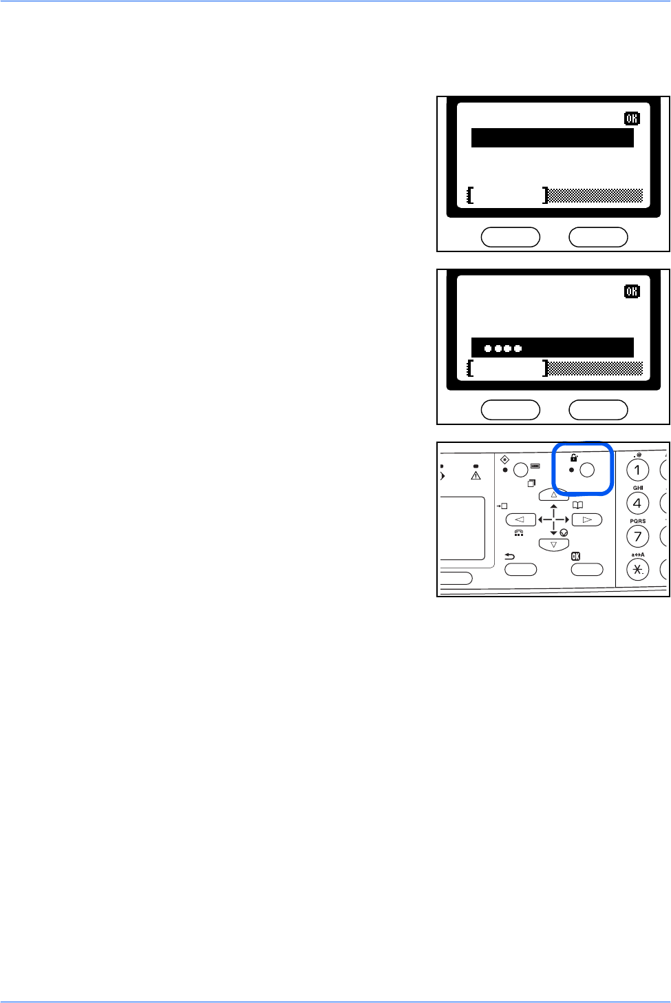
Entering User Login
If the message display prompts you to login, follow the instructions below:
1Use the numeric keys to enter the User ID.
2When the password has been set, press T
to select Password, use the numeric keys to
enter the Password and press Enter. The
basic screen is displayed.
If the administrator has not set the
password, press Enter. The basic screen is
displayed.
3On completion, press Log Out.
User ID:
Cancel
Password:
1118
Cancel
User ID:
Password:

Setup
20 NETWORK SCANNER SETUP GUIDE
NETWORK SCANNER SETUP GUIDE 21
3 Operation
Basic Scanning Procedure
You can scan documents and send them to e-mail addresses or a folder. The folder
can be on a PC or FTP server. The recipient’s address can be entered from an
internal address book, external address book (LDAP) or using a one-touch key.
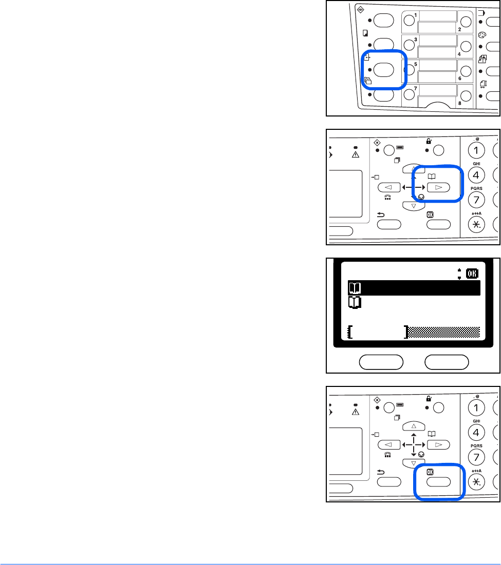
1Press Send.
2Press X.
3Press S or T to select Address Book or Ext
Address Book.
4Press Enter.
Select Addr Book:
Ext Address Book
Address Book
Exit
Operation
22 NETWORK SCANNER SETUP GUIDE
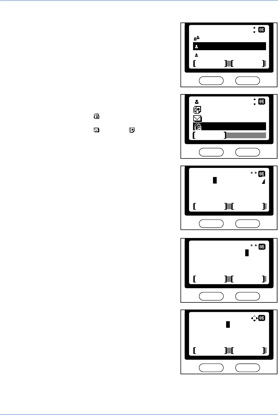
5Press S or T to select a desired name and
press Enter.
6Press S or T to select the destination and
press Enter.
When the (SMB or FTP) is selected, the
login user name input screen is displayed.
When the (E-mail) or (FAX) is
selected, the display shows Completed and
returns to the basic screen. Proceed to step
9.
7Enter the login name and press Enter.
The login name is identical to the login user
name on the destination’s PC (FTP server).
If you also have a domain name, enter it
after the login name. If you are not sure of
the domain name, contact your network
administrator.
8Enter the login password and press Enter.
The display shows Completed and returns
to the basic screen.
The login password is identical to the login
password on the destination's PC (FTP
server).
Address Book:
Harold
ABC
Tiger MenuCancel
Harold
0123456789
Sales_01
Exit
h_pttr@owl-net.net
*
Text
ABC
Cancel
Login Name:
Harold
*
Text
ABC
Cancel
Login Name:
Harold@abcdnet.
*
Text
ABC
Cancel
Login Password:
12345abcde
Operation
NETWORK SCANNER SETUP GUIDE 23
9Press left Select.
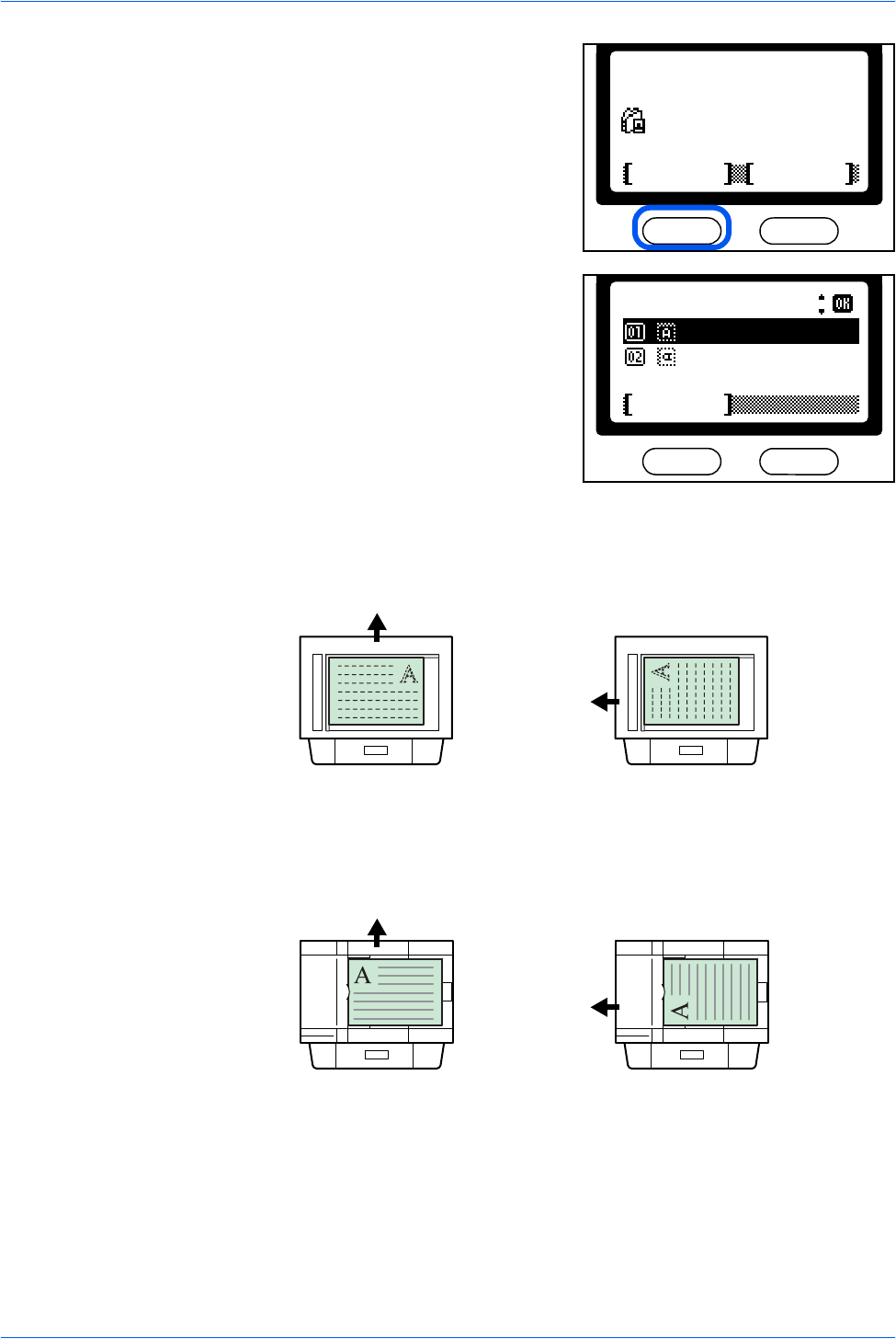
10 Press S or T to select the original
placement required and press Enter. The
display shows Completed and returns to the
basic screen.
Using the Platen
Using the Document Processor
:Sales_01
Ready to send.Dest.
Subject
Placemnt
Left Off
:1
Orig. Placement:
Cancel
*Top Edge to Rear
Top Edge to Left
Top Edge to Rear Top Edge to Left
Rear
Left
Top Edge to Rear Top Edge to Left
Rear
Left
Operation
24 NETWORK SCANNER SETUP GUIDE
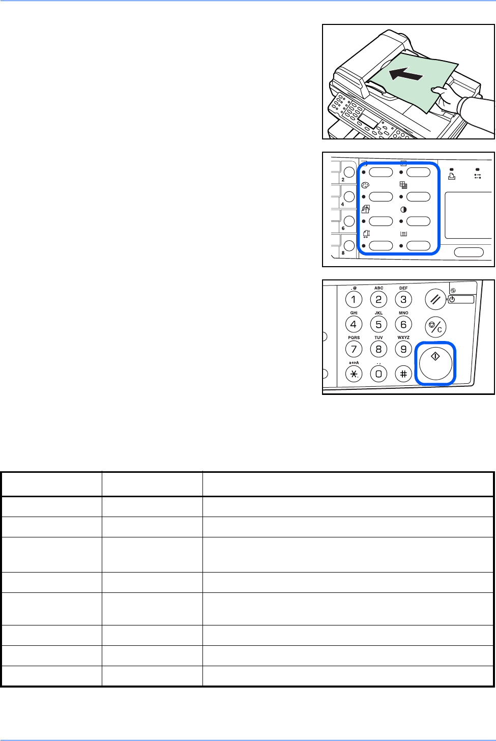
11 Place the original document in the
document processor or on the platen.
12 Program the settings as required to use
additional functions.
To change the default value, refer to
Function Defaults in the table below.
13 Press Start. The Scanning screen is
displayed and scanning will begin.
Function Defaults
The following table shows the scanner functions and their available settings. The
default values can be changed .
Function Defaults Available Settings
Scan Color Select Monochrome Full Color, Grayscale, Monochrome
Original Quality Text + Photo Text + Photo, Photo, Text, OCR
Scan Resolution 200 x 200 Fine 200 x 100 Normal, 200 x 200 Fine, 200 x 400 Sup Fine,
300 x 300 dpi, 400 x 400 Ult Fine†, 600 x 600 dpi†
Exposure Manual (Normal) Auto, Manual (Seven levels available)
Send Size A4 or Letter Letter, Legal, Statement, A4, A5, A6, B5, B6, Folio, OficioII,
Others
Zoom Auto Auto, 100%
File Format PDF PDF, TIFF, JPEG (JPEG compression levels available: 1 to 5)
File Name Date and Time Date and Time, Job No.
†. To scan in full color or gray scale with 400dpi or 600dpi resolution, expansion of the internal memory is
required.

A1

Rev. 1.0 2005.12
©2005 KYOCERA MITA Corporation All rights reserved.
