Kyocera KWC-M300 Dual-Band CDMA 1xRTT Digital Wireless Module User Manual
Kyocera Communications, Inc Dual-Band CDMA 1xRTT Digital Wireless Module Users Manual
Kyocera >
Users Manual
Kyocera 300/1xD Module
Data Book
82-G2153-1
24 September, 2008
[DRAFT]
Kyocera Proprietary
This technology is controlled by the United States Government.
Diversion contrary to U.S. Law prohibited.
Data and information contained in or disclosed by this document is information of Kyocera Wireless Corp. By
accepting this material the recipient agrees that this material and the information contained therein is held in confidence
and trust and will not be used, copied, reproduced in whole or in part, nor its contents revealed in any manner to others
without the express written permission of Kyocera Wireless Corp.
.
KYOCERA WIRELESS CORP.
10300 Campus Point Drive
San Diego, CA 92121
Copyright © 2008 Kyocera Wireless Corp. All rights reserved.
Printed in the United States of America.
82-G2153-1 Rev. 001
24 September 2008
Kyocera Proprietary
Table of Contents
1) Introduction
2) Overview of Kyocera Wireless Corp.
3) CDMA Fundamentals
4) CDMA2000 3G
5) Module Overview
6) Key Features
7) FCC Compliance Statement and Warning
[This page left intentional BLANK.]

Chapter 1
INTRODUCTION
Scope of document
This document will give you information about our M300 and 1xD Modules, that will help you
decide if these products are a match for your requirements. The information contained in this
documents expands on the basic information found on the published Specification Sheets for the
M300 and 1xD modules and gives some perspective on the application of these modules.
For more detailed information on the best ways to implement these modules, please consult the
documents listed below.
If you have any questions about this material or want to report any errors, please send them to:
module-support@kyocera-wireless.com
As with all of our documentation, please check periodically, to see that you have the latest
version of this guide, on our iSupport site:
http://service.kyocera-wireless.com
If you do not have login credentials to this site, talk to your Kyocera Wireless representative, or
send an email request to module-support@kyocera-wireless.com.
1.1 Related Documents
Document Number Title
82-G2090-1 Kyocera 300/1xD Module Systems Integrator’s Guide
82-G2091-1 Kyocera 300/1xD Module KMIP Reference Guide
82-G2092-1 Kyocera 300/1xD AT Reference Guide
82-G2093-1 Kyocera 300/1xD Module BREW Reference Guide
82-G2094-1 Kyocera 300 /1xD Module User’s Guide
82-G2148-1 Kyocera 300/1xD Module Quick Start Guide
82-G2233-1 Kyocera 300/1xD Module Provisioning Guide
82-K4410-1 Kyocera Programming Kit User’s Guide
82-K9145-1 Kyocera Module Development Kit Quick Start Guide
Revision History
[This page left intentionally BLANK.]

CHAPTER 2
Overview of Kyocera Wireless Corp.
Our Vision
Kyocera Wireless connects people worldwide with exciting and easy-to-use communication
technology. We produce mobile handsets and other wireless products with a simple philosophy to
make technology feel natural and intuitive in your hands. Our company leads by pushing the
frontier of wireless communications and consumer lifestyle markets, while maintaining our strong
commitment to an environmentally responsible world, to our employees and communities, and to
the shareholders we serve.
Our Mission
We provide an effortless wireless experience by delivering innovative, high-quality products that
are easy to use.
Our History
You may not know it, but whether listening to your stereo or playing a game on your computer,
there's a good chance you're using Kyocera products in your daily life. That's because Kyocera
Corporation, headquartered in Kyoto, Japan, has been developing high-tech products, high-
performance materials and electronic components since 1959.
Kyocera Wireless Corp. was formed when Kyocera acquired the terrestrial handset division from
CDMA pioneer QUALCOMM, Inc. in February 2000 (read related press release>>). Since that
time, the company, headquartered in San Diego, California, has expanded its operations to
include facilities in India and Brazil, and today employs more than 1600 people globally. As a
wholly-owned subsidiary of Kyocera International Inc., Kyocera Corp.'s North American holding
company, Kyocera Wireless Corp. enjoys the full benefits of this relationship.
Our Company
At Kyocera Wireless Corp., we always keep people in mind. We ask the right questions - What
features would be helpful for people? How could we make this easier to use? - while innovating
the next-generation wireless phones that drive our industry.
And the phone is just one part of the value chain for us. Our parent company, Kyocera
Corporation, creates everything from electronic components to wireless networks. It's a principle
we call vertical integration - and it ensures we're delivering the highest standard of quality in all
aspects of our business.
Kyocera Corporation and its family of companies are recognized worldwide for their commitment
to the environment and to the people and communities they serve. Kyocera Wireless Corp.
shares those same values. We believe working with nature and the communities that support us
is key to our success. You'll see proof of this in our people-focused products and in the way we
interact with the environment and the communities that support us.
Overview of M2M Division
Kyocera Wireless Corp. has been actively involved in the M2M Machine to Machine world since
the release of its award winning Kyocera 200 Module in 2003. Its adoption into the AVL, Meter
Reading, Telemetry, and other industries, from its inception, is a testament to Kyocera's foresight,
engineering expertise and support. The M2M Division leverages the resources of Kyocera.
About Kyocera Wireless M2M Modules
Kyocera Wireless offers a suite of machine-to-machine wireless modules designed to enable real-
time communications over CDMA 1xRTT networks. The modules range from the simplified, data-
only Kyocera 1xD to the Kyocera 300, which integrates the latest QUALCOMM chipsets for a
streamlined form factor, lower power consumption, and extended operating temperatures while
also adding stand-alone GPS capability to digital voice and packet data communications.
The M300 and the 1xD modules are built around QUALCOMM's 'second generation' QSC single
chip solution, the QSC6055.
SUPPORT
The M2M Division of Kyocera Wireless Corp. takes pride is providing the highest level of
technical support to assist your engineering team in the integration of your solution.
• Assistance with integration, FCC and carrier acceptance

Chapter 3
CDMA Fundamentals
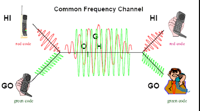
CDMA uses 1.23 MHz per channel. This means all users can transmit at the same time,
relying on codes to differentiate the users. CDMA also uses sectored cells to increase
capacity, like in the advanced mobile phone service (AMPS), but CDMA can use one
frequency in all sectors of the cell instead of following a frequency reuse scheme.
CDMA uses correlative codes to let each user operate under substantial interference.
For example, in a crowded cocktail party, people are talking at the same time but you
are able to listen and understand only one person at a time. This is because your brain
can sort out the voice characteristics of the one with whom you are speaking and
differentiate that voice from the others. As the party grows larger, each person must talk
louder and the size of the talk zone grows smaller. Thus the number of conversations is
limited by the overall noise interference in the room.
CDMA is similar to this cocktail party analogy, but the recognition is based on digital
codes. The interference is the sum of all other users on the same CDMA frequency, both
from within and outside the home cell and from delayed versions of these signals. It also
includes the usual thermal noise and atmospheric disturbances. Delayed signals caused
by multipath are separately received and combined in CDMA.
CDMA cocktail party example
How CDMA works
Cellular frequency reuse patterns
One of the major capacity gains with CDMA is from its frequency reuse efficiency. To eliminate
interference from adjacent cells, narrowband FM systems must physically separate cells using
the same frequency. Complex frequency reuse planning must be done in such a system to
maximize capacity while eliminating interference. A reuse pattern for analog and time division
multiple access (TDMA) systems employs only one-seventh of the available frequencies in any
given cell. With CDMA, the same frequencies are used in all cells and can be used in all sectors
of all cells.
This reuse is possible because CDMA is designed to decode the proper signal in the presence of
high interference. Adjacent cells using the same frequency in CDMA simply cause an apparent
increase in the channel background noise. By allowing the use of the same frequencies in every
cell, CDMA has approximately six times the capacity of existing analog cellular systems.
CDMA concept
CDMA starts with a narrowband signal. Through specialized codes this spreads to a bandwidth of
1.23 MHz. The ratio of the spread data rate to the initial data rate is called the processing gain.
For IS-95 standard CDMA with an 8 kbps vocoder, the processing gain is 21 dB. When
transmitted, a CDMA signal experiences high levels of interference dominated by the coded
signals of other CDMA users. This takes two forms:
• Interference from other users in the same cell
• Interference from adjacent cells
The total interference also includes background noise and other spurious signals.
When the signal is received, the correlator recovers the desired signal and rejects the
interference. The correlators use the processing gain to pull the desired signal out of the noise.
Since a signal-to-noise ratio of 7 dB is required for acceptable voice quality, this leaves 14 dB of
extra processing gain to extract the desired signal from the noise. This is possible because the
interference sources are uncorrelated (orthogonal in the case of the forward link).
CDMA versus analog FM
CDMA channels are defined by various digital codes as well as by frequency.
The capacity for CDMA is soft, not rigid. In analog systems, when all available channels are in
use, no further calls can be added. Capacity in CDMA can be increased with some degradation of
the error rate or voice quality, or can be increased in a given cell at the expense of reduced
capacity in the surrounding cells.
Another advantage of CDMA is the use it makes of diversity. There are three types of diversity:
• Spatial diversity
• Frequency diversity
• Time diversity
Spatial diversity
Spatial diversity takes two forms:
• Two antennas
The base station uses two receive antennas for greater immunity to fading.
This is the classical version of spatial diversity. AMPS analog cellular base stations use
this type of diversity for improved fading resistance.
• Multiple base stations
Multiple base stations simultaneously talk to the mobile phone during soft handoff.
Frequency diversity
Frequency diversity is inherent in a spread-spectrum system. A fade of the entire signal is less
likely than with narrowband systems. Fading is caused by reflected images of an RF signal
arriving at the receiver such that the phase of the delayed (reflected) signal is 180° out of phase
with the direct RF signal.
Since the direct signal and the delayed signals are out of phase, they cancel each other, causing
the amplitude seen by the receiver to be greatly reduced. In the frequency domain, a fade
appears as a notch and is on the order of one over the difference in the arrival time of two
signals. For a 1 µsec delay, the notch is approximately 1 MHz wide.
The Telecommunications Industry Association (TIA) CDMA system prescribes a 1.23 MHz
bandwidth, so only those multipaths of time less than 1 µsec actually cause the signal to
experience a deep fade. In many environments, the multipath signals arrive at the receiver after a
much longer delay, causing only a narrow portion of the signal to be lost. In a fade 20 to 200 kHz
wide, this results in the complete loss of an analog or TDMA signal but only reduces the power in
a portion of a CDMA signal. As the spreading width of a CDMA signal increases, so does its
multipath fading resistance.
Time diversity
Time diversity is a technique common to most digital transmission systems. Signals are spread in
time through interleaving. Interleaving the data improves the performance of the error correction
by spreading errors over time.
Errors in the real world during radio transmission usually occur in clumps, so when the data is de-
interleaved, the errors are spread over a greater period of time. This allows the error correction to
fix the resulting smaller, spread-out errors. Forward error correction is applied, along with
maximal likelihood detection. The particular scheme used for CDMA is convolutional encoding in
the transmitter with Viterbi decoding using soft decision points in the receiver.
Another form of time diversity occurs in the base station when transmitting at reduced data rates.
When transmitting at a reduced data rate, the base station repeats the data resulting in full rate
transmission. The base station also reduces the transmitted power when it operates at reduced
data rates. This added redundancy in the transmitted signal results in less interference (power is
lowered) and improves the CDMA mobile station receiver performance during high levels of
interference.
Synchronization
For any direct sequence spread spectrum radio system to operate, all mobiles and base stations
must be precisely synchronized. If they are not synchronized, it becomes nearly impossible to
recover the codes used to identify individual radio signals. Precise synchronization also leads to
other benefits:
• It allows such services as precise location reporting for emergency or travel usage.
• It allows the use of rake receivers for improved reception in multipath fading conditions.
Rake receiver
Instead of trying to overpower or correct multipath problems, CDMA takes advantage of the
multipath to provide improved reception quality. CDMA does this by using multiple correlating
receivers and assigning them to the strongest signals. This is possible because the CDMA mobile
is synchronized to the serving base station. The mobile receiver can distinguish between direct
and reflected (multipath) signals because of the time delay in receiving the reflected signals.
Special circuits called searchers are also used to look for alternate multipaths and for neighboring
base station signals. The searchers slide around in time until they find a strong correlation with
their assigned code. Once a strong signal is located at a particular time offset, the search assigns
a receiver element to demodulate that signal. The mobile receiver uses three receiving elements,
and the base station uses four. This multiple correlator system is called a rake receiver.
As conditions change, the searchers rapidly reassign the rake receivers to handle new reception
conditions. While each signal being processed by an individual rake receiver experiences fading,
the fades are independent because different path lengths are experienced by each signal. Thus
the receiver can coherently recombine the outputs of the three rake receivers to reconstruct a
much more robust version of the transmitted signal. In this way, CDMA uses multipath signals
to create a more robust receiver. The rake receivers also allow soft handoff as one or more
receivers can be assigned to another base station.
There are some limitations to this scheme. If strong, short transmission paths are present, such
as in a very narrow canyon, the rake receiver system cannot function. If the arrival time of a
multipath signal is less than one clock cycle of the CDMA system, the rake receiver cannot tell
the difference between direct and reflected signals. It has been found, however, that in real world
situations longer time-delayed signals coexist when very strong short multipath signals are
present. This allows the searchers to find these other longer delayed signals under these difficult
propagation conditions.
CDMA reverse link power control
One of the fundamental enabling technologies of CDMA is power control. Since the limiting factor
for CDMA system capacity is the total interference, controlling the power of each mobile is critical
to achieve maximum capacity. CDMA mobiles are power controlled to the minimum power that
provides acceptable quality for the given conditions. As a result, all mobile signals arrive at the
base station at approximately equal levels. In this way, the interference from one unit
to another is held to a minimum.
Two forms of power control are used for the reverse link:
• Open loop power control
• Closed loop power control
Open loop power control
Open loop power control is based on the similarity of the loss in the forward path to the loss in the
reversed path. (Forward refers to the base-to-mobile link, while reverse refers to the mobile-to-
base link.)
Open loop power control sets the sum of transmit power and receive power to a constant,
nominally -73 dBm (IS-98-A). A reduction in signal level at the receive antenna results in an
increase in signal power from the transmitter. For example, when the received power from the
base station is -85 dBm, this is the total energy received in the 1.23 MHz receiver bandwidth. It
includes the composite signal from the serving base station as well as from other nearby base
stations on the same frequency.
The open loop transmit power setting for a received power of -85 dBm would be +12 dBm. By the
IS-98 specification, the open loop power control slew rate is limited to match the slew rate of
closed loop power control directed by the base station. This eliminates the possibility of a sudden
transmission of excessive power by the open loop power control in response to a receiver signal-
level dropout.
Closed loop power control
Closed loop power control is used to allow the power from the mobile unit to deviate from the
nominal as set by open loop control. This is done with a form of delta modulation. The base
station monitors the power received from each mobile station and commands the mobile to either
raise power or lower power by a fixed step of 1 dB. This process is repeated 800 times per
second, or every 1.25 msec.
The power control data sent to the mobile from the base station is added to the data stream by
replacing the encoded voice data. This process is called “puncturing” because the power control
data is written into the data stream by overwriting the encoded voice data. The power control data
occupies 103.6 µsec of each 1.25 msec of data transmitted by the base station.
Because the mobile’s power is controlled no more than is needed to maintain the link at the base
station, a CDMA mobile typically transmits much less power than an analog phone. The base
station monitors the received signal quality 800 times per second and directs the mobile to raise
or lower its power until the received signal quality is adequate. This operating point varies with
propagation conditions, the number of users, and the density and loading of the surrounding cells.
Analog cellular phones must transmit enough power to maintain a link even in the presence of a
fade. Analog phones usually transmit excess power. CDMA radios are controlled in real time and
kept at a power level that maintains a quality transmission based on the changing RF
environment.
Mobile power bursting
Each 20 msec frame in IS-95 is divided into 16 power control groups. When the mobile transmits,
each power control group contains 1536 data symbols (chips) at a rate of 1.2288 Mbps. When the
vocoder moves to a lower data rate, the CDMA mobile bursts its output by sending only the
appropriate number of power control groups. For example, transmitted groups are randomized to
spread the transmitted power over time. For each lowering of the data rate, the transmitted power
is reduced by 3 dB.
CDMA system time
As mentioned earlier, both mobiles and base station in direct sequence CDMA must be
synchronized. In the IS-95 system, synchronization is based on the Global Positioning System
(GPS) time. Each CDMA base station incorporates a GPS receiver to provide exact system
timing information for the cell. The base station then sends this information to each mobile via a
special channel. In this manner, all radios in the system can maintain near-perfect
synchronization.
Most designs also include atomic clocks to provide a backup timing reference. These are capable
of maintaining synchronization for up to several hours. The GPS clock used for CDMA system
time is then used to drive the long code pseudo-random sequence generator.
Closed loop power control puncturing
Once the data has been scrambled with the user-specific long code, the closed loop power
control data is then punctured into the data stream. Power control bits are sent every 1.25
msec—once in every power control group (a CDMA frame is 20 msec, with each frame having 16
1.25 msec power control groups).
Since the power control bits replace the encoded voice data, holes (missing data) are introduced
into the data stream from the receiver’s point of view. These holes are accepted and the system
uses the Viterbi decoder in the receiver to restore the data lost by puncturing. The recovery of the
missing data uses some of the available processing gain in the system. The resulting loss of
capacity has been accounted for in the system’s design.
Another way to think of this is that slightly more power is required to maintain the link because of
the missing data introduced by the power control puncturing. The power control data is sent only
once in the 14.4 kbps case since the reduced processing gain results in higher power being
transmitted from the base station to maintain an acceptable signal-to-noise ratio. The higher
power results in a much lower symbol error rate and the need to send the power control data
twice is eliminated.
Walsh code spreading
In the forward channel (cell-site-to-mobile), the Walsh codes provide a means for uniquely
identifying each user. A Walsh code generator provides 1 of the 64 codes to scramble the
encoded voice data.
• Walsh code 0 = pilot channel
• Walsh code 32 = synchronous channel
• Walsh code 1 to 7 = paging channels
• Other Walsh codes = forward paging channel
Respreading the short sequence
If all cells used the same 64 Walsh codes without another layer of scrambling, the resulting
interference would severely limit the system capacity.
Since all cells can use the same frequency (frequency domain), and all cells use the same Walsh
codes (code domain), the only other means to allow cells to reuse the same Walsh codes is by
using time offset (time domain). This final layer of scrambling uses another code called the short
code to allow reuse of the Walsh codes and to provide a unique identifier to each cell.
Because everything in CDMA is synchronized to system time, it is possible to have each cell site
identified by using a time offset in the short sequence. These “PN offsets” are separated by
multiples of 64 1.2288 Mbps clock chips. This allows for 512 unique time offsets for cell
identification (32768 bits/64 bits = 512 offsets). By scrambling the Walsh encoded channels with
the short code, each base station can reuse all 64 Walsh codes and be uniquely identified from
other adjacent cells using the same frequency.
Forward link channel format
The base station transmitter signal is the composite of many channels (with a minimum of four).
The pilot channel is unmodulated (Walsh code 0); it consists of only the final spreading sequence
(short sequences). The pilot channel is used by all mobiles linked to a cell as a coherent phase
reference and also provides a means for mobiles to identify cells from each other. The other three
channels are:
• Sync channel
• Paging channel
• Traffic channel
These channels use the same data flow, but different data are sent on each channel.
Sync channel
The sync channel transmits time-of-day information. This allows the mobile and base to align
clocks, which form the basis of the codes that are needed by both to make a link. Specifically,
one message sent by the sync channel contains the state of the long code feedback shift
registers 320 msec in the future. By reading this channel, the CDMA mobile can load the data into
its long code generator, and then start the generator at the proper time. Once this has been
accomplished, the CDMA mobile has achieved full synchronization. The sync channel always
uses Walsh code channel 32.
Paging channel
The paging channel is the digital control channel for the forward link. Its complement is the
access channel, which is the reverse link control channel. One base station can have multiple
paging channels and access channels if needed. Up to seven Walsh code channels can be
allocated for use as paging channels. The first paging channel is always assigned to Walsh code
1. When more paging channels are required, Walsh codes 2 through 7 are used.
Traffic channel
The traffic channel is equivalent to the analog voice channel. This is where actual conversation
takes place. The remaining Walsh codes are assigned to traffic channels as required. At least 55
Walsh codes are available for use as traffic channels. The actual number that can be used is
determined by the total interference levels experienced in any given cell. Nominal full loading
would typically be around 30 traffic channels in use for equally loaded cells.
Once all of the various channels are Walsh modulated, they are converted into I/ Q format, re-
spread with the I and Q short sequences, low pass filtered to reduced occupied bandwidth, and
converted into analog signals. The resulting analog I and Q signals from all channels are summed
together and then sent to the I/Q modulator for modulation into an RF carrier.
CDMA reverse link physical layer
The CDMA reverse link uses a different coding scheme to transmit data. Unlike the forward link,
the reverse link does not support a pilot channel for synchronous demodulation (since each
mobile station would need its own pilot channel). The lack of a pilot channel is partially
responsible for the reverse link’s lower capacity than the forward link. In addition, Walsh codes
cannot be used for channelization since the varying time delays from each mobile to the base
station destroys the orthogonality of the Walsh codes. (Varying arrival time makes the Walsh
codes non-orthogonal.)
Since the reverse link does not benefit from non-interfering channels, this reduces the capacity of
the reverse link when compared to the forward link (all mobiles transmitting interfere with each
other). To aid reverse link performance, the 9600 bps voice data uses a one-third (1/3) rate
convolutional code for more powerful error correction. For the 14,400 bps vocoder, the
convolutional encoder is only a half rate encoder that doubles the data rate. Thus the data rate
coming out of the convolutional encoder is the same for either the 9.6 or 14.4 Kbps voice
channels. Then, six data bits at a time are taken to point at one of the 64 available Walsh codes.
The data, which is at 307.2 Kbps, is then XOR’ed with the long code to reach the full 1.2288
Mbps data rate. This unique long code is the channelization for the reverse link.
Reverse error protection
To improve the performance of the reverse link, a more powerful convolution encoder is
used. The third-rate encoder used in the reverse link outputs three 9600 bps data
streams when driven with a single 9600 data stream. This provides increased error
correction capability, but also increases the data rate to 28,800 bps.
64-ary modulation
Walsh codes are not used to provide the channelization in the reverse link. In the
reverse link they are used to randomize the encoded voice data with a modulation
format that is easy to recover. Each six serial data bits output from the convolutional
encoder are used to point to one of the 64 available Walsh codes (26 = 64). This
modulation has the effect of increasing the data rate 10.67 times to 307 Kbps. As the
incoming voice data changes, a different Walsh code is selected. Since this type of
modulation can output one of 64 possible codes, it is referred to as 64-ary modulation.
Reverse channel long code spreading
CDMA mobiles use the same pseudo-random number (PN) sequences as the base for
final short sequence scrambling. An extra one half period clock delay in the mobile’s Q
channel produces offset quadrature phase shift keying (QPSK) modulation rather than
straight QPSK modulation. Thus mobiles can use a simpler and more efficient power
amplifier design. Offset QPSK modulation prevents the signal from going to zero
magnitude and greatly reduces the dynamic range of the modulated signal. Less costly
amplifiers can be used on CDMA mobiles because of the reduced linear dynamic range
obtained with offset QPSK modulation.
CDMA turn-on process
System access
When the mobile is first powered on, it must find the best base station. This is similar to
analog, where the phone scans all control channels and selects the best one. In CDMA,
the mobile unit scans for available pilot signals, which are all on different time offsets.
This process is made easier because of the fixed nature of these offsets.
The timing of any base station is always an exact multiple of 64 system clock cycles
(called chips) offset from any other base station. The mobile selects the strongest pilot
tone and establishes a frequency and time reference from this signal. The mobile then
demodulates the sync channel, which is always on Walsh code 32. This channel
provides master clock information by sending the state of the 42 bit long code shift
register 320 ms in the future. Once the mobile has read the sync channel and
established system time, the mobile uses the parameters from the sync channel to
determine the long code mask being used by the cell site it is acquiring.
Sync channel message
The sync channel messages contains:
• CDMA protocol revision supported by the cell site
• Minimum protocol revision supported by a CDMA mobile to work with the cell site
• System and network identification numbers for the cell site
• PN offset of the cell site
• Paging channel data rate
• Timing parameters – including such items as local time offset from system time and a flag
for indicating if daylight savings time is active in the area
Read the paging channel
At this point the mobile demodulates the paging channel and decodes all of the data contained in
the various messages supplied on the paging channel. If required by the parameters on the
paging channel, the phone then registers with the base station. If the phone is a slotted mode
phone, it must first register with the base station before it can be paged.
The slotted paging channel mode lets the phone save power by going to sleep and only
awakening when it is time to check for a page from the base station. During registration, the time
slot for the phone to wake up and listen is negotiated between the base and mobile. Once this is
completed, the phone is ready to place or receive phone calls.
Paging channel messages
The paging channel is the heart of a CDMA base station. All parameters and signaling necessary
for the proper operation of a CDMA cell site are handled by the paging channel. The paging
channel supports a number of distinct messages that provide information and send messages.
The system parameters message provides the mobile with system information such as the
network, system and base station identification numbers, the number of paging channels
supported, registration information, and the soft handoff thresholds.
The access parameters message provides information to the mobile that dictates the behavior of
access probes when a CDMA mobile initiates a call. The neighbor list message tells the mobile
that the PN offsets of surrounding cell sites may become likely candidates for soft handoffs.
The CDMA channel list reports the number of CDMA frequencies supported by the cell site as
well as the configuration of surrounding cell sites.
The slotted and non-slotted page messages lets the cell site page CDMA phones for incoming
calls. CDMA mobiles operating in the slotted mode must first register with the cell site before they
can be paged. This registration is required to establish which slot is used by the cell site to
transmit the page to the mobile.
The channel assignment message is used to communicate the information needed to get the
mobile onto a traffic channel.
Other supported messages on the paging channel include various types of
signaling messages and authentication.
CDMA idle state handoff
The mobile has searchers scanning for alternative pilot channels at all times. If a pilot channel is
found from another base station that is strong enough for a link, the mobile requests a soft
handoff if it crosses into a new zone. In this case, the CDMA cells must have commanded the
CDMA mobile to perform zone-based registration to reregister the phone.
CDMA call initiation
Keying in a phone number and pressing the Send key initiates an access probe. The mobile uses
a special code channel called the access channel to make contact with the cell site. CDMA
mobiles can transmit two types of channels on the single physical channel provided by the
reverse link. These two channels are distinguished by the types of coding used.
The access channel is used by the mobile to initiate calls. The other possible channel is the traffic
channel, which is used once a call is established. The long code mask used for access probes is
determined from parameters obtained from the sync and paging channels. The parameters are
the access channel number, the paging channel number, the base station ID, and the pilot PN
offset used by the base station.
Before a link is established, closed-loop power control is not active. The mobile uses open-loop
control to estimate an initial level. Multiple tries are allowed, with random times between the tries
to avoid collisions that can occur on the access channel. For each cell site there is also a limited
number of supported access channels, again to reduce the odds of collisions because of the
limited number of access channel receivers in the base station.
CDMA call completion
After each access attempt, the mobile listens to the paging channel for a response from the base
station. If the base station detects the access probe from the mobile, it responds with a channel
assignment message. This message contains all of the information required to get the mobile
onto a traffic channel. This message includes such information as the Walsh code channel to be
used for the forward traffic channel, the frequency being used, and the frame offset to indicate the
delay between the forward and reverse links.
Once the mobile has acknowledged the channel assignment message, the base station initiates
the land link and the mobile moves from the access channel to the traffic channel. To
accommodate signaling, IS-95 supports two methods for temporarily grabbing the traffic channel:
• Blank and burst signaling
• Dim and burst signaling
Both are similar except that the blank and burst steals a contiguous block of frames to transmit
signaling messages, while dim and burst reduces the vocoder rate and then uses the remaining
traffic channel time to more slowly send signaling messages.
Chapter 4
cdma2000 3G
The International Telecommunications Union (ITU), working with worldwide industry bodies,
implemented the IMT-2000 program to develop standards for 3G systems. cdma2000, one of the
most important of the ITU IMT-2000 standards, is the first 3G technology to be commercially
deployed.
CDMA2000 3G standard
Five terrestrial standards were developed as part of the IMT-2000 program. CDMA2000 1X, like
CDMA2000 3X, is an ITU-approved, IMT-2000 (3G) standard. It is part of what the ITU has
termed IMT-2000 CDMA MC, and was sanctioned along with four other terrestrial IMT-2000
standards (listed below) when ITU-R completed the Recommendations in late 1999.
IMT2000 terrestrial radio interfaces:
• IMT-2000 CDMA Multi-Carrier (MC) - CDMA2000 1X and 3X
• IMT-2000 CDMA Direct Spread (DS) - WCDMA (UMTS)
• IMT-2000 CDMA TDD - Ultra TDD and TD-SCDMA
• IMT-2000 TDMA Single Carrier - UWC-136/EDGE
• IMT-2000 FDMA/TDMA-DECT
The cdma200 family of standard
The cdma2000 family of standards specifies a spread-spectrum radio interface that uses Code
Division Multiple Access (CDMA) technology to meet the requirements for 3G wireless
communication systems. The standards in the family are:
IS-2000-1, Introduction to cdma2000 Standards for Spread Spectrum Systems
IS-2000-2, Physical Layer Standard for cdma2000 Spread Spectrum Systems
IS-2000-3, Medium Access Control (MAC) Standard for cdma2000 Spread Spectrum Systems
IS-2000-4, Signaling Link Access Control (LAC) Standard for cdma2000 Spread Spectrum
Systems
IS-2000-5, Upper Layer (Layer 3) Signaling Standard for cdma2000 Spread Spectrum Systems
IS-98-D, Recommended Minimum Performance Standards for cdma2000 Spread Spectrum
Systems
Relationship to TIA/EIA-95-B
cdma2000 provides full backward compatibility with TIA/EIA-95-B. This permits cdma2000
infrastructure to support TIA/EIA-95-B mobile stations and permits cdma2000 mobile stations to
operate in TIA/EIA-95-B systems. The cdma2000 family also supports reuse of existing TIA/EIA-
95-B service standards, such as those that define speech services, data services, Short Message
Services, and Over-the-Air Provisioning and Activation services, with the cdma2000 physical
layer.
cdma2000 and spectrum
cdma2000 is not constrained to only the IMT band; it is defined to operate in all existing allocated
spectrum for wireless telecommunications, thereby maximizing flexibility for operators.
Furthermore, cdma2000 delivers 3G services while occupying a very small amount of spectrum
(1.25 MHz per carrier), protecting this precious resource for operators.
These bands include:
• Cellular (824-849 and 869-894 MHz)
• PCS (1850-1910 and 1930-1990 MHz)
• TACS (872-915 and 917-960 MHz)
• JTACS (887-925 and 832-870 MHz)
• KPCS (1750-1780 and 1840-N870 MHz)
• NMT-450 (411-493 MHz, not continuous 10 MHz spacing)
• IMT-2000 (1920-N980 and 2110-2170 MHz)
• 700 MHz (776-794 and 746-764 MHz)
cdma2000 evolution
cdma2000 is evolving to continue to meet the future demands of the wireless marketplace. The
cdma2000 1xEV standards will provide data-optimized channels, offering data rates well in
excess of the ITU IMT-2000 2 Mbps requirement.
cdmaOne (IS-95-A):
• Voice
• Data up to 14.4 Kbps
cdmaOne (IS-95-B):
• Voice
• Data up to 115 Kbps
cdma2000 1X
• 2X increases in voice capacity
• Up to 307 Kbps packet data on a single (1.25 MHz or 1X) carrier in new or existing
spectrum
• First 3G system for any technology worldwide
cdma2000 1X has been commercially available since October 2000.
cdma2000 1xEV
• Optimized, very high-speed data (Phase 1)
• Up to 2.4 Mbps (downlink) packet data on a single (1.25 MHz) carrier
• Integrated voice and data (Phase 2); up to 4.8 Mbps
•
cdma2000 1xEV is an evolution of cdma2000 1X. 1xEV-DO (Data Only) uses a separate 1.25
MHz carrier for data and offers peak data rates of 2.4 Mbps. 1xEV-DV (Data-Voice) integrates
voice and data on the same carrier.
Kyocera 300/1xD Modules and cdma2000
The Kyocera 300 and 1xD Modules implement cdma2000 1X technology. The Module provides
dual-mode operation CDMA in the 800 MHz cellular band and CDMA PCS in the 1900 MHz PCS
band. The Kyocera 300 and 1xD Modules also support data rates up to 153.6 Kbps in the reverse
and forward links.
Support of E911 Phase 2 Position Location
It is a requirement of the FCC that 25% of new handset sales be Automatic Location Identification
(ALI)-capable by December 31, 2001. AFLT (Advanced Forward Link Trilateration) alone is not
accurate enough to meet the accuracy requirements of the mandate. With AGPS and AFLT, the
Kyocera 300 Module provides the capabilities required for a handset-based voice solution utilizing
an assisting element on the network called the PDE (Position Determination Equipment).
Messaging between the Module and the network is supported by IS- 801.1. The FCC’s accuracy
requirement for a system supporting E911 Phase 2 is 50 meters 67% of the time and 150 meters
95% of the time.
E911 Phase 2: 50 meters 67% of the time and 150 meters 95% of the time
[This page left intentionally BLANK.]
Chapter 5
Module Overview
What is a CDMA 1xRTT Module?
The Kyocera 300 Module and 1xD Module are intended for use by vendors and manufacturers
who would like to design, build, and sell a wireless product using CDMA technology. These
Modules are suited for business applications like remote metering or security, point of sale,
wireless vending, and vehicle tracking. They can support enterprise-wide needs like wireless
voice and data solutions for automotive telematics and handheld devices.
Embedded Module
The Kyocera 300 Module is a fully functional wireless phone designed to be embedded into
another piece of hardware. It then provides wireless connectivity to that device for the purposes
of transferring telemetry data and providing remote monitoring, control, and asset tracking.
The Module integrates easily with your device through a board-to-board connector. Just supply
power, attach an antenna, and use the two serial ports to make and take calls, send and receive
SMS messages, get status, and get a GPS location fix. (It incorporates A-GPS.)
The Module provides state-of-the-art wireless data technology to take advantage of the
nationwide footprint of the 1xRTT networks. It works equally well on both the 800 and 1900
networks.
We at Kyocera Wireless Corp. have applied our expertise in design and manufacturing of CDMA
phones to the creation of an extremely robust, high-performance module. And because the
Kyocera 300 Module is provisioned like a phone, you can get service for it through CDMA cellular
service providers.
What can it do?
The CDMA service providers support voice and various levels of data services, SMS messaging,
and GPS location capabilities. Because the Kyocera 200 Module is designed around the core
technology upon which we build our phones, it can utilize all of those services.
Today, well over 100 million consumers worldwide rely on CDMA for clear, reliable voice
communications and leading-edge data transmission. In North America CDMA is the dominant
wireless technology, and elsewhere it is being adopted in Central and South America as well as
China, and India. Over 35 countries have either commercial or trial activity ongoing. CDMA will
continue to lead in delivering the most advanced 3G services around the world. Kyocera Wireless
Corp. has approved devices operating on many carriers’ networks, and the list is continually
growing.
Will it work in my application?
The chances are: Yes.
Please call us so that we can answer your questions concerning the integration of our technology
into yours.
What is the process to evaluate the module?
Our Module Development Kit is available for evaluation upon execution of a nondisclosure
agreement. With our Module Development Kit you can begin working with the Module
immediately to try out its capabilities.
What is included in the development kit?
We provide everything you need to get started, including extensive documentation and an
interface board for immediate connection to your computer’s serial ports.
How do I integrate the Module into my product from a mechanical perspective?
The Module footprint, pin-out, and connector specifications are provided in our Integration Guide.
How do I integrate the Module into my product from an electronic perspective?
Integration is made easy with serial ports at TTL levels.
How do I integrate the Module into my product from a software perspective?
The Module uses an enhanced AT command set and our proprietary KMIP protocol for enhanced
power and flexibility. These are available on both UARTs and the USB port.
What must I do to get my final product approved for service?
There is a certification process for FCC and carrier approval. But we will help
you get through the process quickly and keep the costs to a minimum.
Module Benefits
The CDMA Module provides access to the CDMA wireless networks without need for engineering
a CDMA product from ASIC level up. The time-to-market advantage saves resources and
provides access to the latest wireless data technology.
The Module is the core technology of KWC’s CDMA phones. It has been repackaged to provide a
ready-to-integrate product. The developer can then concentrate on the specific application and
hardware development application. The CDMA technology within the Module includes the RF and
digital signal processing, analog audio interface, and serial interface. This is the basis from which
to build a device.
User features
The phone Module provides a complete solution to all functionality of a dual-mode cellular phone
minus the keypad, display, and battery. The Module was developed to allow the system integrator
to build CDMA-based devices and to allow very fast time to market. Applications might include a
complete phone, a data modem, or an embedded component in a more powerful device that
needs voice and/or data connectivity in a small form factor.
Definitions of subsystems
Module
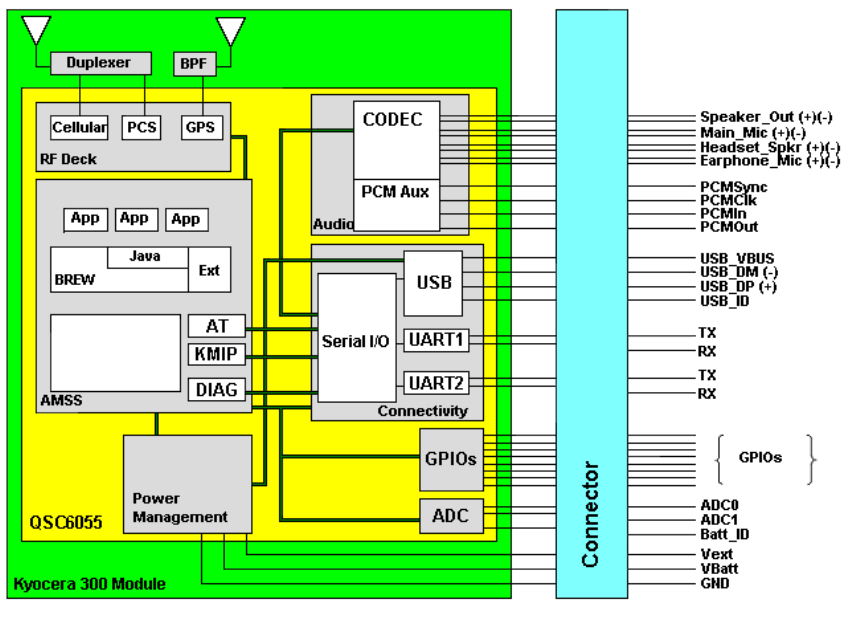
The following figure shows that it is possible to build a full-featured voice phone with the addition
of an external user microprocessor, LCD, keypad, and battery. This figure also shows a typical
module interface.
The Module card includes the following circuits, with the necessary filtering and AGC circuits to
meet performance requirements.
• MSM5100 ASIC
• Memory
• Power management
• Audio
• Transmit and receive
RF interface/antenna ports
Two 50 ohm coaxial RF connectors have been provided for Module testing and integration
into an end user device. The OEM developer must provide a 50 ohm antenna that works in
the desired frequency band of operation.
Wireless data service
The convergence of wireless telephony with mobile computing is making wireless data services a
reality. Among the services and capabilities that can be expected are:
• Direct access to the Internet
• Diagnostic and monitoring applications
• Email capabilities for telephones, PDAs, and connected devices
• Access to corporate intranets from vehicles and remote sites
Data standards supported
• IS-99 – Circuit Switched Data
• IS-657 – Packet Switched Data
• IS-707-A – The combined CDMA Data Standard
• Quick Net Connect (not a standard)
Full documentation for TIA standards can be obtained from Global Engineering in Colorado
(http://www.global.ihs.com) at 800-854-7179.
References
• http://www.3GPP2.com
• http://www.tiaonline.com
• http://www.cdg.org
• http://www.fcc.gov
Carrier requirements must be acquired from each individual operator.
Description of the Kyocera 300 Module
Kyocera 300 Module
The compact Kyocera 300 M2M Module leverages the latest QUALCOMM chipset technology in
order to provide integrated voice, data and autonomous GPS capabilities, based on a smaller
footprint for more widespread integration. The expanded 300 Module feature set includes fully
integrated autonomous GPS that offers “in service” cost advantages over Assisted-GPS.
The Kyocera 300 Module with integrated GPS is designed to enable M2M applications such as
fleet management, asset tracking, telematics, security, wireless vending, roadside call boxes and
wireless point-of-sale terminal applications.
Description of 1xD
Kyocera 1xD Module
The Kyocera 1xD Module makes low-cost M2M solutions a reality for entry-level telemetry
applications. With a lower price point, reduced power consumption and smaller envelope size, the
1xD’s remote capabilities can help improve business operations and productivity while reducing
total cost of ownership.
The Kyocera 1xD Module is designed to enable telemetry M2M data applications such as
metering, security, wireless vending, exception reporting and wireless point-of-sale terminal
applications to name a few.
Overview of GPS capabilities
GPS capabilities are only available in the M300 module and not the 1xD module.
Intelligent multimode GPS
Fully integrated autonomous GPS - standalone GPS
The M300 can get a location fix using the GPS system completely on its own. This means that it
does not require network service and connection to get a fix.
Assisted GPS
The M300 can use both user plane and control plane assisted GPS. Unlike the older systems that
required a brief tune away from to the wireless phone network so that it could tune into and
receive the satellite data, the M300 can talk to the PDE and get GPS info at the same time.
Simultaneous-GPS makes the location acquisition faster and more reliable.
UARTS - Ports of Call
Suggested strategies for utilization
There are 2 UARTS and 1 USB port which are configurable for various protocols such as AT,
DIAG, KMIP, NMEA, PPP etc, one at a time.
You can pick and choose which UARTS, 2 serial and 1 USB that you want to use. Its nice to be
able to use one port to have a call going, while you are using another to control, get status or do
logging.
The power of KMIP
• Fast and comprehensive
• Speed development by porting legacy applications written for the M200.
Enhanced AT command set
In addition to the legacy IS-707A AT command set. These modules have an enhanced AT
command set which includes many GSM-like commands.
[This page left intentionally BLANK.]
CHAPTER 6
KEY FEATURES
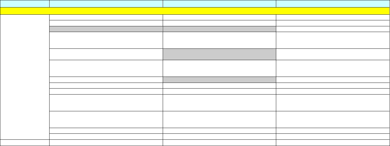
Feature Kyocera 300 Kyocera 1xD Kyocera 200
CDMA CDMA Cellular 800 MHz CDMA Cellular 800 MHz CDMA Cellular 800 MHz
CDMA PCS 1900 MHz CDMA PCS 1900 MHz CDMA PCS 1900 MHz
AMPS 800 MHz
IS-2000 (CDMA2000 Release 0) MOB_P_REV6
radio configurations and features
IS-2000 (CDMA2000 Release 0) MOB_P_REV6
radio configurations and features
IS-2000 (CDMA2000 Release 0) MOB_P_REV6
radio configurations and features
Intelligent multimode GPS - standalone and
assisted, Streaming NMEA Position location capabilities IS-801.1— E911
Release 1.0 and A-GPS Phase II Support
IS-95A/IS-95B (JSTD-008) backward compatibility
(MOB_P_REV1,3,4,5)
IS-95A/IS-95B (JSTD-008) backward compatibility
(MOB_P_REV1,3,4,5)
IS-95A/IS-95B (JSTD-008)
13K, QCELP and EVRC-B (4GV) vocoders 13K QCELP and EVCR vocoders
TIA/EIA-683A; OTASP and OTAPA TIA/EIA-683A; OTASP and OTAPA TIA/EIA-683A; OTASP and OTAPA
TIA/EIA-637A; two-way SMS TIA/EIA-637A; two-way SMS TIA/EIA-637A; two-way SMS
TIA/EIA-707A; data service options, Packet Data
and CSD
TIA/EIA-707A; data service options, Packet Data
and CSD TIA/EIA-707A; data service options, Packet Data
and CSD
TIA/EIA-835C; (TCP/IP/PPP) Simple IP and
Mobile IP
TIA/EIA-835C; (TCP/IP/PPP) Simple IP and
Mobile IP TIA/EIA-835C; (TCP/IP/PPP) Simple IP and
Mobile IP
TIA/EIA-98E minimum RF performance TIA/EIA-98E minimum RF performance TIA/EIA-98E minimum RF performance
Data Throughput 153.6 Kbps Data Throughput 153.6 Kbps Data Throughput 153.6 Kbps
Chipset QUALCOMM QSC6055 QUALCOMM QSC6055 QUALCOMM MSM5100

Feature Kyocera 300 Kyocera 1xD Kyocera 200
PHYSICAL
Dimensions &
Weight Length: 44.5 mm
Width: 33.9 mm
Thickness: 5.4 mm
Weight: Approximately 12.1 g
Length: 44.5 mm
Width: 33.9 mm
Thickness: 5.4 mm
Weight: Approximately 12.1 g
Length: 64.8 mm
Width: 48.2 mm
Thickness: 11.4 mm
Weight: Approximately 38 g
Operational
Temperature
Range
-20° C to +60° C (-4° F to 140° F)
Note: The module is designed to be fully
compliant to RF performance guidelines
throughout the operational temperature range.
-20° C to +60° C (-4° F to 140° F)
Note: The module is designed to be fully
compliant to RF performance guidelines
throughout the operational temperature range.
-22° to 140°F (-30° to 60°C)
Functional
Temperature
Range
-30° C to +85° C (-22° F to 185° F)
Note: Additional improvements have been made
to provide an extended functional temperature
range in which the module can operate with
certain degradation of RF performance.
-30° C to +85° C (-22° F to 185° F)
Note: Additional improvements have been made
to provide an extended functional temperature
range in which the module can operate with
certain degradation of RF performance.
-22° to 140°F (-30° to 60°C)
Storage
Temperature
Range
-40° C to +105° C (-40° F to 185° F) -40° C to +105° C (-40° F to 185° F) -40° to +185°F (-40° to +85°C)
RoHS
YES YES
Antenna
Connectors Separate Hirose UFL-R-SMT (50-Ohm)
connectors for CDMA and GPS applications
Note: See Integrator's Guide for details.
Separate Hirose UFL-R-SMT (50-Ohm)
connectors for CDMA and GPS applications
Note: See Integrator's Guide for details.
• MMCX sub-miniature RF connector
(50-Ohm) for CDMA and AMPS applications
• MMCX sub-miniature RF connector
(50-Ohm) for position location applications
Power Supply VEXT Pins +4.2 to +5.5 VDC
VBAT Pins +3.4 to +4.2 VDC
Note: See Integrator's Guide for details.
VEXT Pins +4.2 to +5.5 VDC
VBAT Pins +3.4 to +4.2 VDC
Note: See Integrator's Guide for details.
+3.6 to + 4.2VDC
Board to Board
Interface
Connector
Molex “SlimStack” 80-pin 0.5mm pitch connector
• Power
• Analog Audio
• Serial-UART 1 and UART 2
• Digital control
• GPIOs
• I2C
• PCM Audio
• USB
Note: See Integrator's Guide for details.
Molex “SlimStack” 80-pin 0.5mm pitch connector
• Power
• Serial-UART 1 and UART 2
• Digital control
• GPIOs
• I2C
• USB
Note: See Integrator's Guide for details.
Molex 50 Pin Molex
• Power
• Analog audio
• Serial-UART 1 and UART 2
• Digital control

Feature Kyocera 300 Kyocera 1xD Kyocera 200
Feature Set
Dual NAM Dual NAM Dual NAM
IMSI IMSI IMSI
SPC/SPC3 SPC/SPC3 SPC/SPC3
General
Services
MEID/ESN MEID/ESN ESN
System Selection 2.0 System Selection 2.0 System Selection 1.0
Cust_Config Cust_Config Cust_Config
Call Processing
Expanded PRL (MAX 16K) Expanded PRL (MAX 16K) PRL (MAX 4K)
Embedded TCP/IP Stack with
Server Functionality Embedded TCP/IP Stack with
Server Functionality Embedded TCP/IP Stack (Client Only)
DCTM 2.0 (Data Call Throttling Mechanism) DCTM 2.0 (Data Call Throttling Mechanism) Data Retry
Dynamic/Static IP address Dynamic/Static IP address Dynamic/Static IP address
MIP Deregistration MIP Deregistration MIP Deregistration
PDSN Change PDSN Change PDSN Change
SMS while dormant SMS while dormant SMS while dormant
Voice call while dormant Voice call while dormant
Dormancy Dormancy Dormancy
IPv4 IPv4 IPv4
Data Services
Simple IP/ Mobile IP Simple IP/ Mobile IP Simple IP/ Mobile IP
AERIS® AERIS® digital services AERIS® digital services
Messaging SMS (Inbox) SMS (Inbox) SMS Relay Mode Only
OTAPA/OTASP OTAPA/OTASP OTAPA/OTASP
DMU DMU DMU
OMA DM OMA DM OMA DM
IOTA IOTA IOTA
FOTA / FUMO FOTA /FUMO
OTA Services
Native PRL Download Native PRL Download
gpsOne gpsOne
Control/User Plane Control/User Plane
M-based GPS
Stand-Alone GPS
Streaming NMEA
Base Station Latitude/ Longitude Base Station Latitude/ Longitude Base Station Latitude/ Longitude
LBS Services
GPS Mode Select
iKyo Interface iKyo Interface
iAT Interface iAT Interface
BREW
API API

Feature Kyocera 300 Kyocera 1xD Kyocera 200
Keypad Emulation
Enhanced AT command set Enhanced AT command set AT command set
APIs
KMIP (Kyocera Multiplex Interface Protocol) KMIP (Kyocera Multiplex Interface Protocol) KMIP (Kyocera Multiplex Interface Protocol)
UART1 UART1 UART1
UART2 UART2 UART2
USB USB
Virtual COM Ports Virtual COM Ports
Communication
Interfaces
I2C BUS I2C BUS
Battery Charging Battery Charging
Over-Voltage Protection Over-Voltage Protection
Power
Management
Power Mode Control Power Mode Control
AT Profile Feature AT Profile Feature AT Profile Feature
Factory Reset Factory Reset
Recovery
Services
Crash Dump Analyzer Crash Dump Analyzer
Carrier Detect (DCD) Carrier Detect (DCD) Carrier Detect (DCD)
Ring Detect Ring Detect
Programmable GPIOs Programmable GPIOs
PDMs PDMs
Pin Behavior
ADCs ADCs
Analog Audio Analog Audio
TTY/TDD with VCO and HCO TTY/TDD
E911 E911
PCM Audio
Audio
Audio over USB
[This page left intentionally BLANK.]

Chapter 7
Compliance and Warning Statement (FCC & IC)
Regulatory Information
This Section outlines important regulatory notices concerning the M300 module.
FCC ID: OVFKWC-M300
IC: 3572A-M300
FCC Notice: This device complies with part 15 of the FCC rules. Operation is subject to the
following two conditions:
(1) This device may not cause harmful interference, and
(2) this device must accept any interference received, including interference that may cause
undesired operation.
Industry Canada Notice: Operation is subject to the following two conditions: (1) this device may
not cause interference, and (2) this device must accept any interference, including interference that
may cause undesired operation of the device. The term “IC:” before the radio certification number
only signifies that Industry Canada technical specifications were met.
1. This Class B digital apparatus complies with Canadian ICES-003.
2. Cet appareil numérique de la classe B est confome à la norme NMB-003 du Canada.
Warning: The Kyocera 300 Module has been certified by the Federal Communications
Commission (“FCC”). Unauthorized modifications or changes not expressly approved by Kyocera
Wireless Corp. (“Kyocera”) could void compliance with regulatory rules, and thereby your authority
to use this equipment.
Warning: This equipment has been tested and found to comply with the limits for a Class B digital
device, pursuant to part 15 of the FCC Rules. These limits are designed to provide reasonable
protection against harmful interference in a residential installation. This equipment generates, uses
and can radiate radio frequency energy and, if not installed and used in accordance with the
instructions, may cause harmful interference to radio communications. However, there is no
guarantee that interference will not occur in a particular installation. If this equipment does cause
harmful interference to radio or television reception, which can be determined by turning the
equipment off and on, the user is encouraged to try to correct the interference by one or more of
the following measures.
• Reorient or relocate the receiving antenna.
• Increase the separation between the equipment and receiver.
• Connect the equipment into an outlet on a circuit different from that to which the
receiver is connected.
• Consult the dealer or an experienced radio/TV technician for help.
Caution: The M300 meets the FCC Limits and has been certified as a Module for mobile
operation. The customer may use Kyocera FCC ID on final product to demonstrate conformity as
long as the provided instructions are followed.

1) To avoid any harmful interference to radio communication or any electronic equipment, it is
customer’s responsibility to test the final product at a system level and to ensure the final
product is in compliance with Part 15 of the FCC rules. This test can be performed by any
accredited test facility acceptable by the FCC.
2) To assure optimal performance and maintain compliance with the FCC RF exposure
requirements, always adhere to the following conditions:
1) The external antenna gain including cable loss must not exceed 8 dBi in Cellular band and
12 dBi in PCS band.
2) User must maintain minimum 20 cm spacing between external antenna(s) and all persons
during wireless modes of operation.
3) This device must not be co-location or operated in conjunction with any other antenna or
transmitter.
Use of this device in any other configuration may exceed the FCC RF Exposure compliance
limit.
3) An FCC ID label is on the Module itself. The FCC label must be visible through a window on
the final device or it must be visible when an access panel, door, or cover is easily removed. If
not, a second label must be placed on the outside of the final device containing the following
text:
Contains “FCC ID: OVFKWC-M300”