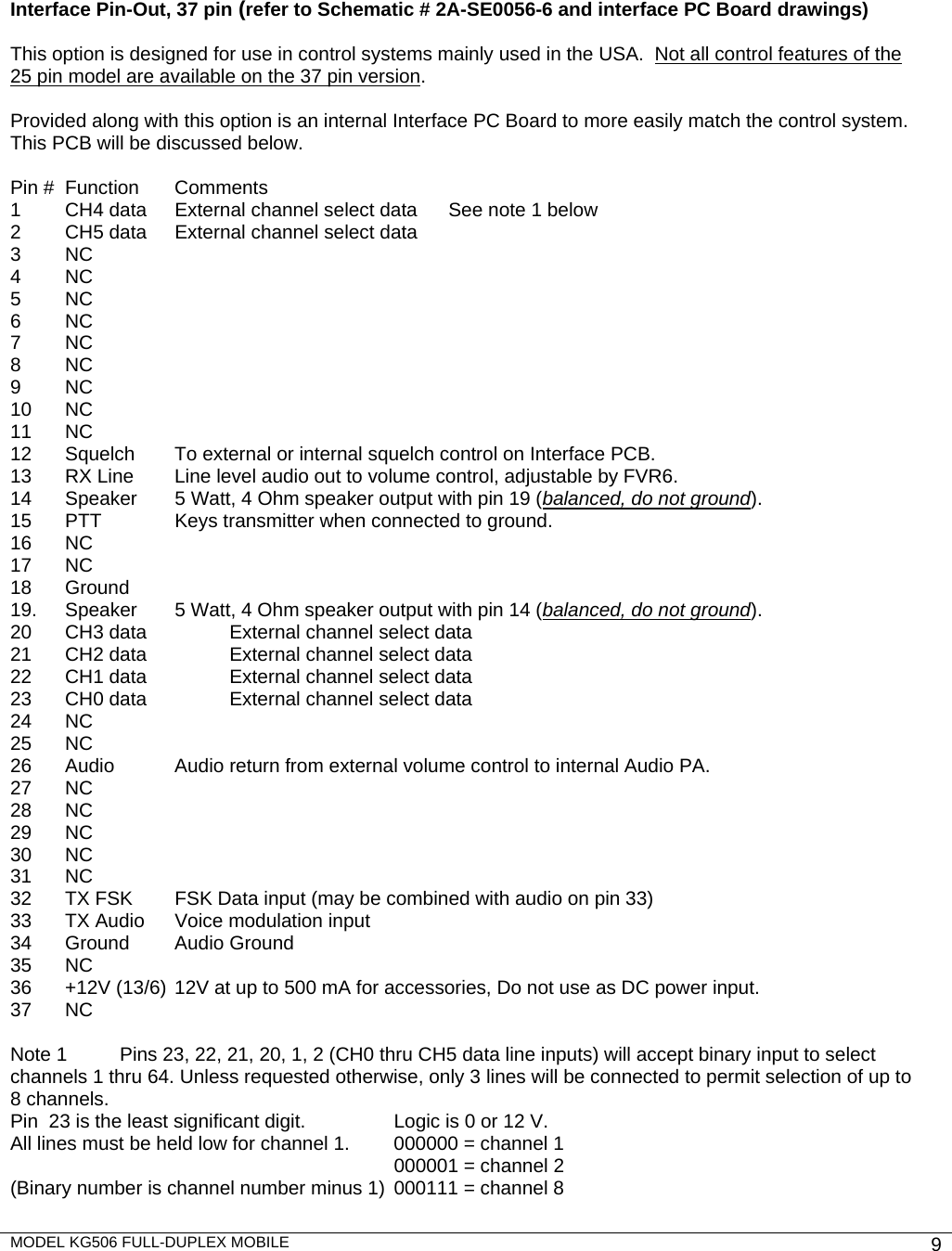
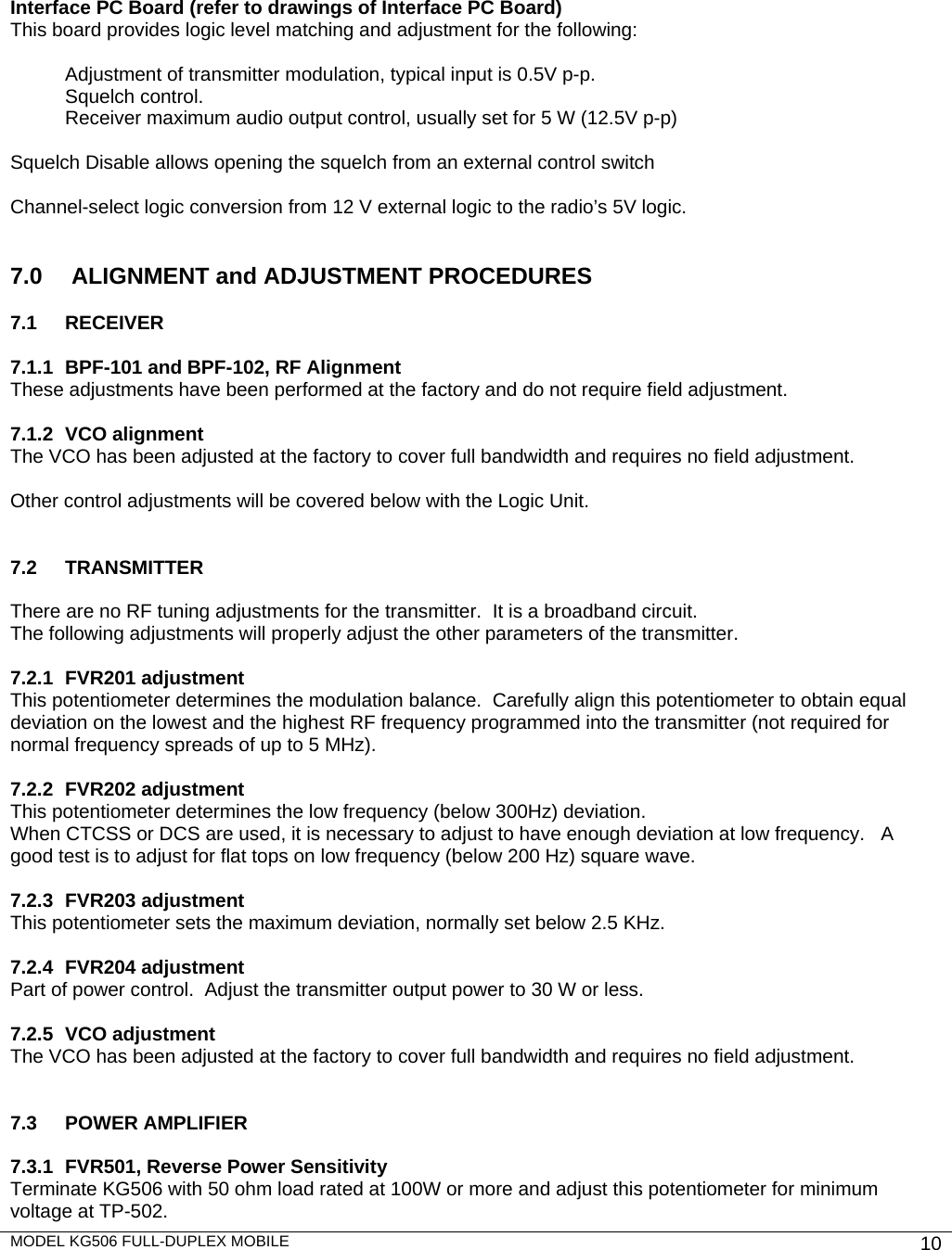
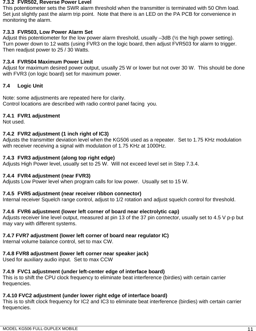
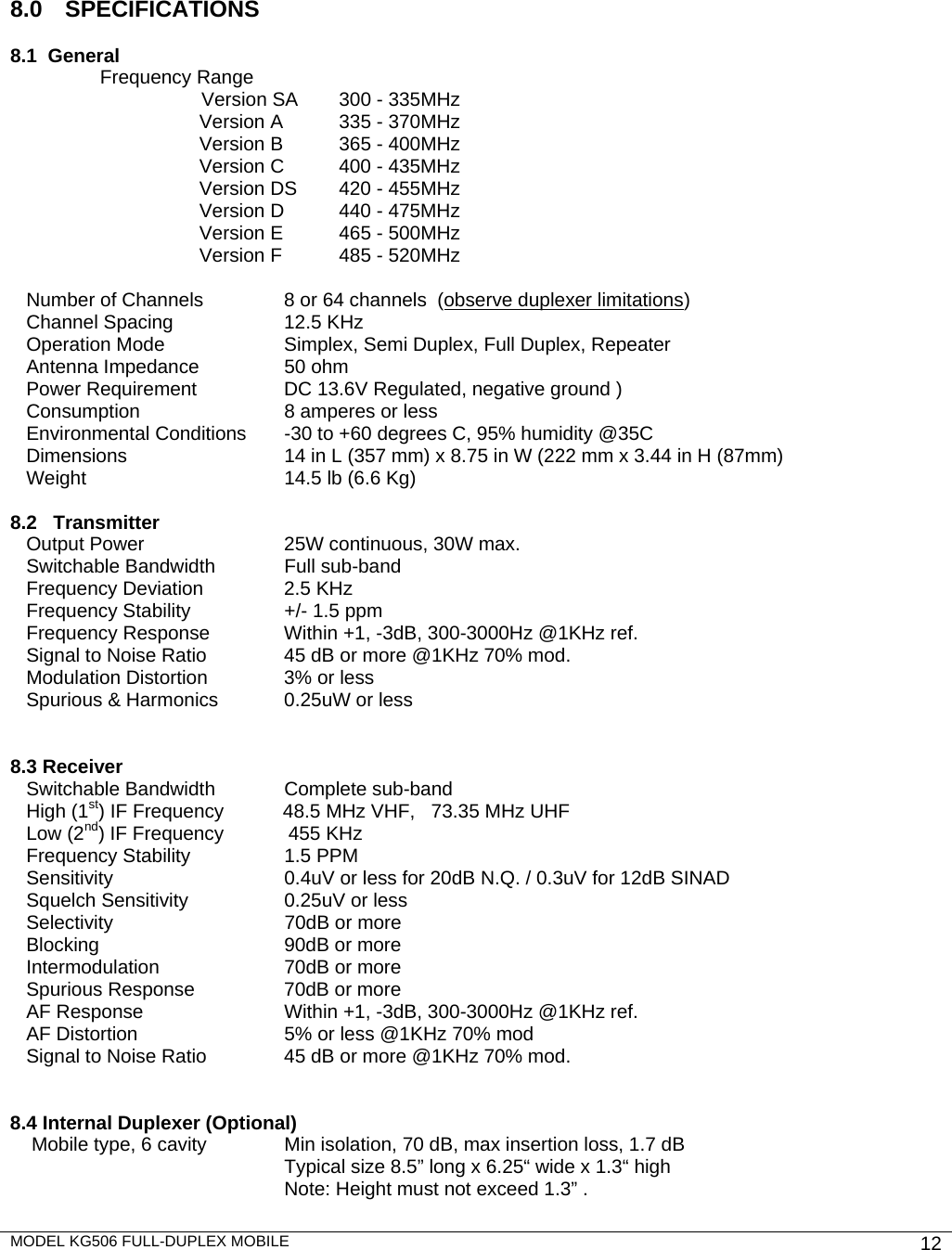
Kyodo West KG50640E FULL-DUPLEX MOBILE RADIO User Manual

Kyodo West Inc FULL-DUPLEX MOBILE RADIO Users Manual

Users Manual

  SERVICE MANUAL   KYODO WEST   MODEL KG506 NT  FULL-DUPLEX TRANSCEIVER  FULL BAND COVERAGE WITHOUT TUNING
MODEL KG506 FULL-DUPLEX MOBILE    2          FCC Compliance Information   THIS DEVICE COMPLIES WITH PART 90 OF THE FCC RULES. OPERATION IS SUBJECT TO THE FOLLOWING TWO CONDITIONS. (1) THIS DEVICE MAY NOT CAUSE HARMFUL INTERFERENCE, AND (2) THIS DEVICE MUST ACCEPT ANY INTERFERENCE RECEIVED, INCLUDING INTERFERENCE THAT MAY CAUSE UNDESIRED OPERATION. Caution: Changes or modifications to this equipment which are not approved by Kyodo West could void the user’s authority to operate the equipment.   (a) Note: This equipment has been tested and found to comply with the limits for a Class B digital device, pursuant to part 90 of the FCC Rules. These limits are designed to provide reasonable protection against harmful interference in a residential installation.   (b) This equipment generates uses and can radiate radio frequency energy and, if not installed and used in accordance with the instructions, may cause harmful interference to radio communications.  However, there is no guarantee that interference will not occur in a particular installation. If this equipment does cause harmful interference to radio or television reception, which can be determined by turning the equipment off and on, the user is encouraged to try to correct the interference by one or more of the following measures: —Reorient or relocate the receiving antenna. —Increase the separation between the equipment and receiver. —Connect the equipment into an outlet on a circuit different from that to which the receiver is connected. —Consult the dealer or an experienced radio/TV technician for help. (c) The provisions of paragraphs (a) and (b) of this section do not apply to digital devices exempted from the technical standards under the provisions of §15.103. (d) For systems incorporating several digital devices, the statement shown in paragraph (a) or (b) of this section needs to be contained only in the instruction manual for the main control unit. (e) In cases where the manual is provided only in a form other than paper, such as on a computer disk or over the Internet, the information required by this section may be included in the manual in that alternative form, provided the user can reasonably be expected to have the capability to access information in that form.
MODEL KG506 FULL-DUPLEX MOBILE    3           1.0     INTRODUCTION  Thank you for purchasing the KYODO WEST MODEL KG506 Full-Duplex Mobile Radio.  This manual contains information to assist you in the application and operation of the radio.  The KG506 is a building block intended for use in systems requiring a compact radio for full duplex, repeater, link, etc.  The radio is capable of both analogue and digital modulation.   The KG506 is designed to operate with an external, custom designed, control system, which may be supplied by Kyodo West or by the customer.  Kyodo West will provide engineering assistance and technical information to assist in the design of the control system by the customer.  Use of the many features available in the radio will depend on the complexity of the control system.  2.0   FEATURES & PRODUCT DESCRIPTION  2.1 Standard Inclusions The KG506 transceiver is supplied complete with the following items:  KG506 transceiver   DC Supply Cable with Fuse and Plug  Operators Manual   Spare Fuse    Two Magnetic Keys           Mounting Plate with Hardware  2.2 Features  Designed for use with external control system Simplex or two frequency Duplex operation Programmable with a PC computer Up to 64 Channels  Optional Internal Duplexer All UHF Frequency Bands from 406 to 500 MHz Transmit Time Limiter to prevent channel jamming   Channel selectable High / Low power CTCSS/DCS on a per channel basis Rugged Housing Heavy gauge mounting plate with key lock Step-Up VCO Voltage for Superior Selectivity Low Stand-by Current is ideal for Solar Installations Watch Dog Timer   2.3 Product Description  The Kyodo West KG506 transceiver represents a great advance on the previous rugged & time proven KG106 transceiver. The radio consists of separate “base station quality” modules all housed within one rugged, compact mobile cabinet. The receiver, the transmitter, and the PA Unit are each enclosed within their own diecast housings that are directly mounted to the main chassis. A full-featured logic module controls all parameters of the radio under the control of a microprocessor. The RF Power Output is programmable to HIGH or LOW power by channel and provides 15 to 30 Watts adjustable. The CTCSS and DCS modules support all EIA tones, which may be set on a per channel basis during radio programming.  The KG506 is supplied with TX and RX antenna ports to allow connection to an external duplexer or feeder cables. Space is provided inside the housing for an antenna relay or mobile type 6-cavity duplexer.  The KG506 is a building block intended for use in systems requiring a compact radio for full duplex, repeater, link, etc.  The radio is capable of both analogue and digital modulation.
MODEL KG506 FULL-DUPLEX MOBILE    4          2.4  Front Panel Features  Beginning at the top left corner and moving clockwise, the front panel includes the following: 1.  UHF Type connector for the Antenna / Transmitter (optional type “N”) LEDs to indicate:  A=POWER, B=BUSY, C=TRANSMIT, D=ALARM, and E=REPEAT MODE 2.  Miniature jack for speaker audio output 3.  BNC Connector for the Receiver 4.  DC Power Connector  5.  37 position D sub connector for interface to the external control system  6.  9 position D sub connector for connection to a PC for programming 7.  Model Number / FCC Label        2.5 Indicator Functions  A    POWER On LED will illuminate Green whenever power is applied to the radio.  B  BUSY Mode LED will illuminate Green whenever the radio receives a signal.   C  TRANSMIT Mode LED will illuminate in Red whenever the radio is transmitting.  D  ALARM Mode LED will flash Amber whenever the radio detects an alarm such as a program problem, 3dB reduction in power output or high VSWR.  E  REPEATER Mode LED will illuminate in Yellow when the selected channel has been   programmed for Repeater operation.       1  32476 5A  B  C  E D
MODEL KG506 FULL-DUPLEX MOBILE    5          3.0 OPERATION  3.1  Installation and Programming KG506 can be installed to operate as Fixed Station, mobile or transportable applications.  The antenna(s) used for base stations must be fixed-mounted on outdoor permanent structures.  RF exposure is addressed at the time of licensing, as required by the responsible FCC Bureau(s), including antenna co-location requirements.  For all applications, follow the precautions below.   DO NOT  transmit if someone is within 0.87 meters of the radio antenna. DO NOT press the transmit switch unless you actually want to transmit. DO NOT allow children to play with any radio equipment containing a transmitter. DO NOT operate the radio near unshielded electrical blasting caps. DO NOT operate the radio in an explosive atmosphere unless the radio is specifically approved for such use. DO NOT operate the radio in a vehicle while refuelling. DO NOT install any fixed (base station) antenna in a location such that it may be approached casually by non-technical personnel.  The KG506 must be programmed before it will operate correctly. This is best done by the equipment supplier or a competent radio engineer. They will require a copy of the FCC station license, correct programming kit and a PC.  Complete programming instructions are provided with the kit.  If a duplexer is used, please observe the maximum frequency spread permitted by the duplexer notches.  It is important that the KG506 be correctly installed at its working location.  Due to the custom nature of each installation, it is recommended that this be done by a competent radio engineer or technician employed by the purchasing agency.  As a minimum, it is necessary to: Securely attach the mounting plate to the desired location. Connect the DC Input power lead to a suitable 13.8 Volt Regulated DC Power supply that has sufficient capacity. (Ensure that the DC Polarity is correct, otherwise the fuse will blow). Connect the antenna feed line(s).  (Check that the VSWR of the antenna system is acceptable). Connect the Control System to the 37 pin sub D connector.  3.2 Basic Operation  Note that controls and functions will vary with different control systems and with programming.  3.3 Switch On Switch the Power Supply "ON” , the POWER indicator should illuminate.    Adjust the Volume Setting    Rotate the Volume Knob clockwise until the audio level from the speaker is suitable.   3.4  Select the Channel  3.5 Receiving You should now be able to hear any radio traffic that occurs on channel. It may be necessary to readjust the Volume setting to suit your listening requirements.  3.6 Transmitting Depending on the legal requirements in your country and the operating requirements within your organization, it may be necessary to announce your Call Sign, and will probably be necessary to announce the Call Sign of the party you are calling at the start of your transmission.
MODEL KG506 FULL-DUPLEX MOBILE    6          Press the PTT switch before beginning to speak.  When transmitting, it is necessary to hold the microphone about 75mm (3") from your mouth and speak clearly into the front of the microphone.   4. CIRCUIT DESCRIPTION / RECEIVER (refer to Schematic # 2A-SA0137-3)  4.1 RF section An incoming signal is fed to pre-selector filters and amplified by Q861 and then fed to post-selector filters.  The RF filters are tuned by varactors D862 thru D866 based on a control voltage derived from the VCO. The output of the RF section feeds the balanced mixer, consisting of IC811 and T801 which produces 48.5MHz (VHF) or 73.35 MHz (UHF) by injection from the 1st local oscillator signal provided by the RX VCO.  4.2  IF & Audio Sections (refer to Schematic # 3A-SA0139-4) The output signal from the balanced mixer, now the High IF signal, is fed to the crystal filters XF801, and then amplified by Q810.  The signal is then fed to the IF Unit.  This module contains additional filters XF001 / 2, amplifier Q001, XF003.  The High IF then passes into 2nd IF processor IC (IC001).  The 2nd local crystal oscillator signal is generated by X001 (48.045 MHz VHF or 72.895 MHz UHF) and fed to IC001 to produce the 2nd (Low IF) signal of 455 KHz.  IC001 amplifies and detects the 455 Low IF 2nd local signal to produce an audio signal.  The audio signal is processed by other components to derive the discriminator audio, the squelch and busy signals.  The audio passes to the main receiver board, amplified and buffered by IC802 and out to the  audio processor IC (IC3) located on the Logic Unit.  IC3 provides band-pass and de-emphasis functions and passes the processed audio to IC16, line amplifier and IC22, Audio PA.  IC16 provides internal repeat audio and external line-level (0 dBm) audio for interfacing external devices.  IC22 provides audio to the speaker jack.  4.3   RX VCO Section (refer to Schematic # 3A-SA0010-7) The oscillator circuit formed by Q301 and associated components produces the 1st local signal Rx frequency minus 48.5MHz, VHF or Rx frequency minus 73.35MHz, UHF.  The frequency of the oscillator is controlled by a signal input from the PLL, (see below) which is applied to varactors D303/304. The signal is amplified by buffer amplifier Q302, IC301 and Q303.  The output signal is fed to the balanced mixer in the receiver RF section. A sample of the frequency is also sent to the PLL. Transistors Q304/ 5/ 6 perform switching and regulating functions.  4.4  RX PLL Section (part of schematic 2A-SA0137-3 receiver) The PLL IC101 contains a pre-scaler and frequency dividers to divide both the VCO frequency and the local reference 12.0 MHz oscillator TCXO801, to a common reference frequency.  These signals are compared by a phase detector to produce a VCO control signal.  This control signal is fed to the charge pump, consisting of Q805, Q806 AND Q807, then to LPF IC808 and on to the VCO. The supply voltage of the charge pump is multiplied by IC102 (approx. 15V) to achieve greater S/N ratio.  The frequency dividers are controlled by data from the Logic Unit to determine receiver operating frequency.   5.0    CIRCUIT DESCRIPTION / TRANSMITTER  (refer to Schematic # 2A-SA0138-1) 5.1  TX VCO section (refer to Schematic # 3A SA0012-6) The oscillator circuit formed by Q301 and associated components produces the final carrier signal.  The frequency of the oscillator is controlled by a signal input from the PLL, (see below) which is applied to varactors D303/304. The oscillator signal is amplified by buffer amplifier Q302, IC301 and Q303.  The output signal is fed to the TX (driver) Unit for further amplification.  A sample of the frequency is also sent to the PLL.  The modulation is applied to varactors D301 and D302. Transistors Q304/ 5/ 6 perform switching and regulating functions.
MODEL KG506 FULL-DUPLEX MOBILE    7            5.2   TX PLL section   The PLL IC101 contains a pre-scaler and frequency dividers to divide both the VCO frequency and the local 12.0 MHz oscillator, OCXO201, to a common reference frequency.  These signals are compared by a phase detector to produce a VCO control signal.  This control signal is fed to the charge pump, consisting of Q205, Q208 and Q209, and fed to the LPF IC209 and on to the VCO. The supply voltage of the charge pump is multiplied by IC210 (approx. 15V) to achieve greater S/N ratio. The frequency dividers are controlled by data from the Logic Unit to determine transmitter operating frequency  5.3 Modulator Section The modulation signal is fed to both VCO and the reference oscillator (OCXO201).  This permits a very flat modulation characteristic against low frequency (DC).  This also permits operation with true digital signals such as Digital Coded Squelch.   5.4  TX Unit (Driver) Section The VCO signal is amplified by Q211 to the proper level to drive the PA Module VIA CN201.    5.5 PA Section The signal from driver stage is amplified by Power Module, PM501 up to 30W output power. The signal is then fed to a balanced line to detect forward and reverse power, then on to the LPF to eliminate harmonics and spurious frequencies.  An APC (Automatic Power Control) circuit stabilizes the output power at the set level.   The circuit also protects the PA from excess reverse power caused by mis-match of the antenna.  An alarm circuit signals if output power drops below a preset level or when SWR exceeds a preset level.  All parameters are adjustable.   6.0   CIRCUIT DESCRIPTION / LOGIC UNIT  (refer to Schematic #  2A-SE0056-6)  6.1 Microprocessor (CPU) CPU, IC1, uPD78F0058Y, an 8-bit processor, has 60K flash memory and 2K RAM inside.  This CPU controls all functions of the KG506 including all software controls and processing programmed data for frequencies, tones, etc.  A flash memory permits ON-BOARD-UP-GRADE when new software is released.  6.2  EE ROM section IC7 is the 64kbit EEROM.  This IC contains all data for channel parameters.  6.3  Audio processor section IC2 and IC3 control all audio processing and encode/decode CTCSS tones for the transmitter and receiver.   6.4  LED display section (front panel of radio) The LED’s indicate each mode of operation of the KG506 as follows:  POWER, BUSY, TRANSMIT, ALARM, REPEATER.  6.5  Audio amplifier section IC22 provides 5 W of audio power to drive 4 ohm external speaker.  Input to the amplifier comes from either the normal receiver audio path controlled by FVR7, or from an external volume control via C68 and FVR8.  6.6  Control Interface Connector Control interface is provided by CN10, a Sub D, 25 or 37 pin female connector on the front panel of the unit.  All I/O required for the operation and control of the radio is available through this connector.  The following list has information regarding pin-out of the 25 pins provided on the on the logic board itself.
MODEL KG506 FULL-DUPLEX MOBILE    8          These pins may be hard-wired to a 37 pin connector which lends itself to customer supplied control systems or may be terminated in an optional 25 pin connector.  The 25 pin option is the most versatile with a full set of control features. Pin-Out for both the 25 pin and 37 pin connectors is provided below.  Interface Pin-Out, 25 pin (refer to the bottom of Schematic # 2A-SE0056-6)  Pin #  Function  Comments   1  CH0    External channel select data  See note 1 below 2  CH1    External channel select data 3  CH2    External channel select data 4  CH3    External channel select data 5  CH4    External channel select data 6  CH5    External channel select data 7 Ground Chassis ground 8  RSSI    Receive Signal Strength Indication: varies from 0.5 V to 3.2 V as                                        signal increases from 0 to saturation. 9  Disc. Out  Discriminator wide band audio output: 1.2V p-p @ 1000 Hz, 70%     Modulation 10  SQ Control  Connects to external squelch control.  11  Busy    Indicates that a signal is being received: switches from near 0V (logic low) for      no signal to near 5V (logic high) when squelch opens. 12  Mute (RX)  Mutes receiver audio when connected to ground. 13  Mod 1   Microphone audio or FSK data input: 50 mV for 70% modulation. 14 Ground  Chassis ground 15  PTT    Keys transmitter when connected to ground. 16  Mod 2   Digital data input: binary data, TTL level  (NOT FSK). 17 Simplex  No function  18  Error    Indicates error / alarm condition:  alternates between 0 and 5V 19. Decode  No function 20  RX audio 1  Provides 0 dBm (variable) output.    See note 2 below 21  RX audio 2  Provides 0 dBm (variable) output.    See note 2 below 22  TX Out  No function 23  Ext Pwr Sw  External control of 12VDC power to the radio. Normally at 5V, turns        radio on when connected to ground.  Usually hard-wired to ground. 24  VR    Bias to external volume control. 25  +12V    12V output to power accessories up to 500 mA.  Note 1    Pins 1 thru 6 will accept 6 digit binary inputs to select the channels 1 thru 64.       Pin 1 is the least significant digit.                Pins 6 5 4 3 2 1     All lines must be held low for channel 1.    000000 = channel 1      (Binary number is channel number minus 1)  000110 = channel 7         111111 = channel 64         000001 = channel 2    Note 2  Either pin 21 or 22 will provide unbalanced output of -6 dBm @ 300 Ohms.  If both are used, a balanced 0 dBm output is available (do not ground either side).  Level is adjusted by control FVR6 on the Logic Unit.
MODEL KG506 FULL-DUPLEX MOBILE    9          Interface Pin-Out, 37 pin (refer to Schematic # 2A-SE0056-6 and interface PC Board drawings)  This option is designed for use in control systems mainly used in the USA.  Not all control features of the 25 pin model are available on the 37 pin version.    Provided along with this option is an internal Interface PC Board to more easily match the control system.  This PCB will be discussed below.  Pin #  Function  Comments   1  CH4 data  External channel select data  See note 1 below 2  CH5 data  External channel select data 3 NC    4 NC  5 NC    6 NC 7 NC 8 NC 9 NC 10 NC 11 NC 12  Squelch   To external or internal squelch control on Interface PCB. 13  RX Line   Line level audio out to volume control, adjustable by FVR6. 14  Speaker  5 Watt, 4 Ohm speaker output with pin 19 (balanced, do not ground).    15  PTT    Keys transmitter when connected to ground. 16 NC   17 NC    18 Ground     19.  Speaker  5 Watt, 4 Ohm speaker output with pin 14 (balanced, do not ground). 20  CH3 data    External channel select data   21  CH2 data    External channel select data 22  CH1 data    External channel select data     23  CH0 data    External channel select data 24 NC    25 NC 26  Audio   Audio return from external volume control to internal Audio PA. 27 NC 28 NC 29 NC 30 NC 31 NC 32  TX FSK  FSK Data input (may be combined with audio on pin 33) 33  TX Audio  Voice modulation input 34 Ground  Audio Ground 35 NC 36  +12V (13/6) 12V at up to 500 mA for accessories, Do not use as DC power input. 37 NC  Note 1  Pins 23, 22, 21, 20, 1, 2 (CH0 thru CH5 data line inputs) will accept binary input to select channels 1 thru 64. Unless requested otherwise, only 3 lines will be connected to permit selection of up to 8 channels. Pin  23 is the least significant digit.      Logic is 0 or 12 V. All lines must be held low for channel 1.    000000 = channel 1         000001 = channel 2 (Binary number is channel number minus 1)  000111 = channel 8
MODEL KG506 FULL-DUPLEX MOBILE    10          Interface PC Board (refer to drawings of Interface PC Board) This board provides logic level matching and adjustment for the following:     Adjustment of transmitter modulation, typical input is 0.5V p-p. Squelch control. Receiver maximum audio output control, usually set for 5 W (12.5V p-p)  Squelch Disable allows opening the squelch from an external control switch  Channel-select logic conversion from 12 V external logic to the radio’s 5V logic.   7.0   ALIGNMENT and ADJUSTMENT PROCEDURES  7.1 RECEIVER   7.1.1  BPF-101 and BPF-102, RF Alignment These adjustments have been performed at the factory and do not require field adjustment.   7.1.2 VCO alignment The VCO has been adjusted at the factory to cover full bandwidth and requires no field adjustment.  Other control adjustments will be covered below with the Logic Unit.   7.2 TRANSMITTER  There are no RF tuning adjustments for the transmitter.  It is a broadband circuit.  The following adjustments will properly adjust the other parameters of the transmitter.   7.2.1 FVR201 adjustment This potentiometer determines the modulation balance.  Carefully align this potentiometer to obtain equal deviation on the lowest and the highest RF frequency programmed into the transmitter (not required for normal frequency spreads of up to 5 MHz).  7.2.2 FVR202 adjustment This potentiometer determines the low frequency (below 300Hz) deviation.  When CTCSS or DCS are used, it is necessary to adjust to have enough deviation at low frequency.   A good test is to adjust for flat tops on low frequency (below 200 Hz) square wave.  7.2.3 FVR203 adjustment This potentiometer sets the maximum deviation, normally set below 2.5 KHz.    7.2.4  FVR204 adjustment  Part of power control.  Adjust the transmitter output power to 30 W or less.  7.2.5 VCO adjustment The VCO has been adjusted at the factory to cover full bandwidth and requires no field adjustment.   7.3 POWER AMPLIFIER  7.3.1  FVR501, Reverse Power Sensitivity Terminate KG506 with 50 ohm load rated at 100W or more and adjust this potentiometer for minimum voltage at TP-502.
MODEL KG506 FULL-DUPLEX MOBILE    11           7.3.2  FVR502, Reverse Power Level This potentiometer sets the SWR alarm threshold when the transmitter is terminated with 50 Ohm load.   Set just slightly past the alarm trip point.  Note that there is an LED on the PA PCB for convenience in monitoring the alarm.  7.3.3  FVR503, Low Power Alarm Set Adjust this potentiometer for the low power alarm threshold, usually –3dB (½ the high power setting).  Turn power down to 12 watts (using FVR3 on the logic board, then adjust FVR503 for alarm to trigger.  Then readjust power to 25 / 30 Watts.  7.3.4  FVR504 Maximum Power Limit Adjust for maximum desired power output, usually 25 W or lower but not over 30 W.  This should be done with FVR3 (on logic board) set for maximum power.   7.4   Logic Unit    Note: some adjustments are repeated here for clarity. Control locations are described with radio control panel facing  you.  7.4.1 FVR1 adjustment Not used.  7.4.2  FVR2 adjustment (1 inch right of IC3) Adjusts the transmitter deviation level when the KG506 used as a repeater.  Set to 1.75 KHz modulation with receiver receiving a signal with modulation of 1.75 KHz at 1000Hz.  7.4.3 FVR3 adjustment (along top right edge) Adjusts High Power level, usually set to 25 W.  Will not exceed level set in Step 7.3.4.  7.4.4  FVR4 adjustment (near FVR3) Adjusts Low Power level when program calls for low power.  Usually set to 15 W.  7.4.5  FVR5 adjustment (near receiver ribbon connector) Internal receiver Squelch range control, adjust to 1/2 rotation and adjust squelch control for threshold.  7.4.6  FVR6 adjustment (lower left corner of board near electrolytic cap) Adjusts receiver line level output, measured at pin 13 of the 37 pin connector, usually set to 4.5 V p-p but may vary with different systems.    7.4.7 FVR7 adjustment (lower left corner of board near regulator IC) Internal volume balance control, set to max CW.  7.4.8 FVR8 adjustment (lower left corner near speaker jack) Used for auxiliary audio input.  Set to max CCW  7.4.9  FVC1 adjustment (under left-center edge of interface board) This is to shift the CPU clock frequency to eliminate beat interference (birdies) with certain carrier frequencies.  7.4.10 FVC2 adjustment (under lower right edge of interface board) This is to shift clock frequency for IC2 and IC3 to eliminate beat interference (birdies) with certain carrier frequencies.
MODEL KG506 FULL-DUPLEX MOBILE    12          8.0 SPECIFICATIONS  8.1  General Frequency Range       Version SA    300 - 335MHz                          Version A    335 - 370MHz                           Version B     365 - 400MHz                          Version C     400 - 435MHz                          Version DS    420 - 455MHz                          Version D      440 - 475MHz                          Version E      465 - 500MHz                          Version F     485 - 520MHz     Number of Channels         8 or 64 channels  (observe duplexer limitations)    Channel Spacing             12.5 KHz    Operation Mode              Simplex, Semi Duplex, Full Duplex, Repeater    Antenna Impedance         50 ohm     Power Requirement           DC 13.6V Regulated, negative ground )    Consumption                  8 amperes or less    Environmental Conditions      -30 to +60 degrees C, 95% humidity @35C    Dimensions                   14 in L (357 mm) x 8.75 in W (222 mm x 3.44 in H (87mm)     Weight                       14.5 lb (6.6 Kg)   8.2   Transmitter    Output Power                  25W continuous, 30W max.    Switchable Bandwidth         Full sub-band    Frequency Deviation          2.5 KHz    Frequency Stability           +/- 1.5 ppm    Frequency Response        Within +1, -3dB, 300-3000Hz @1KHz ref.    Signal to Noise Ratio        45 dB or more @1KHz 70% mod.     Modulation Distortion        3% or less    Spurious & Harmonics       0.25uW or less   8.3 Receiver    Switchable Bandwidth         Complete sub-band      High (1st) IF Frequency           48.5 MHz VHF,   73.35 MHz UHF     Low (2nd) IF Frequency            455 KHz    Frequency Stability           1.5 PPM    Sensitivity                      0.4uV or less for 20dB N.Q. / 0.3uV for 12dB SINAD    Squelch Sensitivity           0.25uV or less    Selectivity                      70dB or more     Blocking                      90dB or more    Intermodulation               70dB or more    Spurious Response           70dB or more    AF Response                  Within +1, -3dB, 300-3000Hz @1KHz ref.    AF Distortion                   5% or less @1KHz 70% mod    Signal to Noise Ratio          45 dB or more @1KHz 70% mod.    8.4 Internal Duplexer (Optional)     Mobile type, 6 cavity     Min isolation, 70 dB, max insertion loss, 1.7 dB           Typical size 8.5” long x 6.25“ wide x 1.3“ high       Note: Height must not exceed 1.3” .

Navigation menu