L 3 Communications Display Systems CM840IC CrewMate 840 Electronic Flight Bag (EFB) User Manual

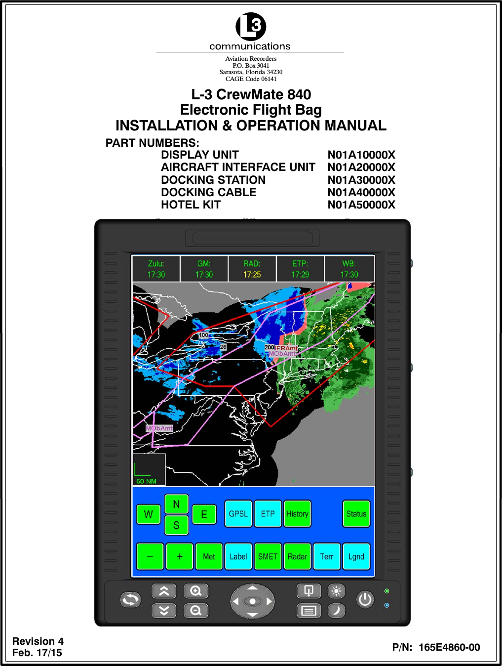
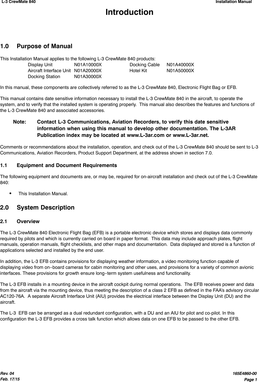
L-3 Communications Corporation, Display Systems CrewMate 840 Electronic Flight Bag (EFB)

User Manual

L-3 CrewMate 840Electronic Flight BagINSTALLATION & OPERATION MANUALRevision 4Feb. 17/15Aviation RecordersP.O. Box 3041Sarasota, Florida 34230CAGE Code 06141PART NUMBERS:DISPLAY UNIT N01A10000XAIRCRAFT INTERFACE UNIT N01A20000XDOCKING STATION N01A30000XDOCKING CABLE N01A40000XHOTEL KIT N01A50000XP/N:  165E4860-00
L-3 CrewMate 840Installation ManualPage iiRev. 04Feb. 17/15165E4860-00CrewMate EFB Installation & Operation ManualPart Number 165E4860-00Revision 4Feb. 17/15EXPORT CONTROL STATEMENT ELECTRONIC FLIGHT BAG TECHNOLOGY / DATA:The CrewMate 840 EFB products/software are being exported from the United States in ac-cordance with the Export Administration Regulations ECCN 7E994, No License Required.Diversion contrary to U.S. law is prohibited.  In accordance with U.S. Law (31 CFR Part 746,and Supplement No.1 to Part 774, and CFR Part 550) resale/re−export or transfer to thecountries identified therein is prohibited without the prior written consent of the U.S. De-partment of Commerce.HTSUS/Schedule B: 4901.10.0040, 4901.10.0000This manual contains date sensitive information. To verify the latest revision level of thismanual, visit our document download site at http://www.L−3ar.net.REGULATORY STATEMENTS FOR FCC AND INDUSTRY CANADA:FCC/Industry Canada Two Part Statement:This device complies with FCC Part 15 and Industry Canada license exempt RSS standard(s). Operation is subject tothe following two conditions: (1) this device may not cause interference, and (2) this device must accept anyinterference, including interference that may cause undesired operation of the device.Cet appareil est conforme à FCC Partie15 d’Industrie Canada RSS standard exempts de licence (s). Son utilisation estsoumise à Les deux conditions suivantes: (1) cet appareil ne peut pas provoquer d’interférences et (2) cet appareil doitaccepter Toute interférence, y compris les interférences qui peuvent causer un mauvais fonctionnement du dispositif.Modification Warning:“Changes or modifications not expressly approved by the party responsible for compliance could void the user’sauthority to operate the equipment.””Les changements ou modifications non expressément approuvés par la partie responsable de la conformité pourraientannuler l’autorité de l’utilisateur à utiliser cet équipement.”ECopyright 2015 by L-3 Communications Corporation Aviation RecordersAll rights reserved.  No part of this manual may be reproduced or utilized in anyform or by any means, electronic or mechanical, including photocopying, re-cording, or by information storage and retrieval system, without permission inwriting.Inquiries should be addressed to:L-3 Communications CorporationAviation RecordersTechnical PublicationsP. O. Box 3041Sarasota, Florida 34230(941) 371–0811FAX: (941) 377–5591CAGE Code 06141
L-3 CrewMate 840 Installation Manual Page iiiRev. 04Feb. 17/15165E4860-00GENERALThis product and related documentation must be reviewed for familiarization withsafety markings and instructions before operation.This instrument was constructed in an ESD (electrostatic discharge) protected envi-ronment.  This is because most of the semiconductor devices used in this instrumentare susceptible to damage by static discharge.Depending on the magnitude of the charge, device substrates can be punctured ordestroyed by contact or the mere proximity of a static charge.  The results can causedegradation of device performance, early failure, or immediate destruction.These charges are generated in numerous ways such as simple contact, separation ofmaterials, and normal motions of persons working with static sensitive devices.When handling or servicing equipment containing static sensitive devices, adequateprecautions must be taken to prevent device damage or destruction.Only personnel who are thoroughly familiar with industry-accepted techniques forhandling static sensitive devices should attempt to service circuitry with these devices.In all instances, measures must be taken to prevent static charge build-up on worksurfaces and persons handling the devices.BEFORE APPLYING POWERVerify that the product is set to match the line voltage and that the correct fusesare installed.Servicing instructions are for use by service-trained personnel only.  To avoid dangerouselectric shock, do not perform any servicing unless qualified to do so.Adjustments described in the manual are performed with power supplied to theinstrument while protective covers are removed.  Energy available at many points may, ifcontacted, result in personal injury.THE CONTENTS OF THEEQUIPMENT CAN BEDAMAGED BY STATIC ELECTRICITY.PROPER HANDLING IS REQUIRED.
L-3 CrewMate 840Installation ManualPage ivRev. 04Feb. 17/15165E4860-00THIS PAGE IS INTENTIONALLY LEFT BLANK
L-3 CrewMate 840 Installation Manual Page vRev. 04Feb. 17/15165E4860-00SERVICE BULLETIN LISTSERVICEBULLETIN DATE DESCRIPTION1July 15/11 INTRODUCTION OF IMPROVED BONDING CHARACTERISTICS (J3)Newly manufactured AIUs include a washer and nut on front panel connector J3, improving the bonding characteristics of the J3 connector.2May 15/12Rev. 1MD1: INTRODUCTION OF IMPROVED ETHERNET CONNECTIVITYThe AIU interface circuit board has been updated to improve the Ethernet connectivity to the aircraft Ethernet.3May 16/12Rev. 1MD1: INTRODUCTION OF IMPROVED ETHERNET CONNECTIVITYThe DU interface circuit board has been updated to improve the Ethernet connectivity to the aircraft Ethernet.4June 27/12Rev. 2IMPROVED NETWORK CONNECTIVITYInstructions for releasing and renewing the IP address acquired by the DU during initial boot up.5May 10/12Rev. 1RESOLVING A LATCHED ETHERNET CONDITIONInstructions for releasing and renewing the IP address acquired by the DU during initial boot up.6May 14/12Rev. 2INTRODUCTION OF SOFTWARE REVISION LProvides changes to the default network settings which increases Ethernet networkreliability. Includes a pre‐defined GUI button allowing for the release and renew ofthe DU IP address on demand. The configuration file has been updated to allow forbetter communication with the DU bezel buttons, preventing inoperability of thesefunctions.7May 8/12 MANUAL NETWORK RE-CONFIGURATIONAlternate set of instructions in situations where the software update detailed in EFBService Bulletin #6 can not be performed. This will re‐configure the DU Ethernet settings into a more reliable configuration allowing for better network communicationwith the on‐board network. These changes will remain in place after rebooting.8Aug. 9/12 MD2: INTRODUCTION OF NEW PROCESSOR BOARD & HARD DRIVEThe processor board and hard drive used in the DU have gone obsolete. Replacement processor board and hard drive have been introduced as replacements.9Aug. 9/12 MD2: INTRODUCTION OF NEW CIRCUIT BOARDSNew circuit boards have been incorporated into the AIU that include the modifications previously incorporated with MD1.10 Apr. 16/13 ENABLING OF WI-FI CAPABILITYInstructions for enabling the Wi‐Fi capability of Display Units shipped with Wi‐Fi disabled.
L-3 CrewMate 840Installation ManualPage viRev. 04Feb. 17/15165E4860-00THIS PAGE IS INTENTIONALLY LEFT BLANK
L-3 CrewMate 840 Installation Manual Page viiRev. 04Feb. 17/15165E4860-00TABLE OF CONTENTSSection PageIntroduction 1.......................................................................................1.0  Purpose of Manual 1............................................................................1.1  Equipment and Document Requirements 1.........................................................2.0  System Description 1............................................................................2.1  Overview 1.....................................................................................2.2  Accessory Overview 2...........................................................................2.3  Hotel Kit Overview 2.............................................................................3.0  Functional Description 2.........................................................................3.1  CrewMate Configuration − Dual Redundant 2.......................................................3.2  Display Unit Configuration 3......................................................................3.3  Bezel Button Operation 5.........................................................................3.4  Aircraft Interface Unit Configuration 5..............................................................3.5  Docking Cradle Configuration 6...................................................................3.6  Cross Talk 8....................................................................................3.7  Operating System 8.............................................................................Installation 9........................................................................................4.0  Aircraft Interface Unit 9..........................................................................4.1  Interface Cable 10...............................................................................4.2  Docking Cradle 11...............................................................................4.3  Display Unit 12..................................................................................4.4  Pre-Installed Software 13.........................................................................4.5  Microsoft Windows Update 14....................................................................4.6  Electronic Flight Bag Graphical User Interface Software 14...........................................4.7  Software Installation Procedure 14................................................................4.8  Touchscreen Calibration 16.......................................................................5.0  Post-Installation Check Out 17....................................................................5.1  EFB Error Messages 18..........................................................................5.2  ARINC 429 Interface 19..........................................................................5.3  ARINC 429 Validation 20.........................................................................Maintenance 23.....................................................................................6.0  Reliability 23....................................................................................6.1  Maintainability 23................................................................................7.0  Scheduled Maintenance and Calibration 23.........................................................7.1  DU Screen Cleaning 23..........................................................................7.2  Li−Ion Battery Particulars 23......................................................................7.3  Battery Electrical Check 23.......................................................................7.3.1  Battery Electrical Check 23.....................................................................7.3.2  Battery Physical Check 24......................................................................7.4  Battery Replacement 25..........................................................................7.5  Coin Battery Replacement 25.....................................................................7.6  Product Support 27..............................................................................7.7  Authorized Repair Facilities 27....................................................................Aircraft Interface Unit Characteristics 29................................................................Docking Assembly Characteristics 29..................................................................Display Unit Characteristics 29........................................................................Display Unit Touch Screen Characteristics 30...........................................................Display Unit Processing Characteristics 30.............................................................Display Unit LCD Characteristics 30...................................................................
L-3 CrewMate 840Installation ManualPage viiiRev. 04Feb. 17/15165E4860-00TABLE OF CONTENTSSection PageDisplay Unit Backlight Characteristics 30...............................................................Applications 31.....................................................................................Reference Documents 33............................................................................8.0  FAA Documents 33..............................................................................8.1  JAA Documents 33..............................................................................8.2  Military Documents 33...........................................................................8.3  Transport Canada Documents 33..................................................................8.4  Non-Government Documents 33..................................................................Hardware Durability and Reliability 35..................................................................LIST OF ILLUSTRATIONSFigure Page1.  L-3 CrewMate Dual Redundant Configuration Block Diagram 3.........................................2.  CrewMate Display Unit Block Diagram 3.............................................................3.  CrewMate Display Unit in Portrait Mode 4...........................................................4.  CrewMate Display Unit Dimensions (in Inches) 4.....................................................5.  DU Front Bezel Key Reference 4...................................................................6.  DU Top Bezel Reference 4........................................................................7.  DU Connection Reference 5.......................................................................8.  CrewMate Aircraft Interface Unit 6..................................................................9.  CrewMate Aircraft Interface Unit Dimensions (in Inches) 6.............................................10.  CrewMate Aircraft Interface Unit Block Diagram 6...................................................11.  CrewMate Docking Cradle Dimensions (in Inches) 7.................................................12.  EFB GUI Cross-Talk Icon 8.......................................................................13.  J1 Pin Outs 9...................................................................................14.  J2 Pin Outs 9...................................................................................15.  J3 Pin Outs 10..................................................................................16.  P4 Connector, Interface Cable 10.................................................................17.  P1 Connector, Interface Cable 10.................................................................18.  Docking Cable 10...............................................................................19.  Docking Cradle Assembly 11.....................................................................20.  Docking Cradle Assembly, Top View 11............................................................21.  Display Unit Seating, Front View 12................................................................22.  Display Unit Seating, Rear View 12................................................................23.  DU Seating, Right Side 12........................................................................24.  DU Seating, Left Side 12.........................................................................25.  DU Seating, Rear 12.............................................................................26.  DU Seating Completed 13........................................................................27.  EFB GUI Interface Icons 14......................................................................28.  Setup GUI Display 15............................................................................29.  Main Menu Configuration GUI Display 15...........................................................30.  On-Screen Display Test 17.......................................................................31.  On-Screen Recalibration 17......................................................................32.  DU Status Display 18............................................................................33.  Tera Term Desktop Icon 20.......................................................................34.  Tera Term New Connection Window 20.............................................................35.  Tera Term New Connection Window 20.............................................................36.  DU Battery Access 24...........................................................................37.  DU Battery Access 25...........................................................................38.  Coin Battery Replacement 26.....................................................................
L-3 CrewMate 840 Installation Manual Page ixRev. 04Feb. 17/15165E4860-00LIST OF TABLESTable Page1.  L-3 CrewMate 840 Electronic Flight Bag Accessory Items 2............................................2.  L-3 CrewMate 840 Electronic Flight Bag Software 2...................................................3.  Hotel Kit, p/n N01A50000X Items 2.................................................................4.  List of A429 Supported Labels 19...................................................................5.  A429 Label Format 21............................................................................
L-3 CrewMate 840Installation ManualPage xRev. 04Feb. 17/15165E4860-00THIS PAGE IS INTENTIONALLY LEFT BLANK
L-3 CrewMate 840 Installation Manual Page 1Rev. 04Feb. 17/15165E4860-00Introduction1.0 Purpose of ManualThis Installation Manual applies to the following L-3 CrewMate 840 products:Display Unit N01A10000X Docking Cable N01A40000XAircraft Interface Unit N01A20000X Hotel Kit N01A50000XDocking Station N01A30000XIn this manual, these components are collectively referred to as the L-3 CrewMate 840, Electronic Flight Bag or EFB.This manual contains date sensitive information necessary to install the L-3 CrewMate 840 in the aircraft, to operate thesystem, and to verify that the installed system is operating properly.  This manual also describes the features and functions ofthe L-3 CrewMate 840 and associated accessories.Note: Contact L-3 Communications, Aviation Recorders, to verify this date sensitiveinformation when using this manual to develop other documentation. The L-3AR Publication index may be located at www.L-3ar.com or www.L-3ar.net.Comments or recommendations about the installation, operation, and check out of the L-3 CrewMate 840 should be sent to L-3Communications, Aviation Recorders, Product Support Department, at the address shown in section 7.0.1.1 Equipment and Document RequirementsThe following equipment and documents are, or may be, required for on-aircraft installation and check out of the L-3 CrewMate840:SThis Installation Manual.2.0 System Description2.1 OverviewThe L-3 CrewMate 840 Electronic Flight Bag (EFB) is a portable electronic device which stores and displays data commonlyrequired by pilots and which is currently carried on board in paper format.  This data may include approach plates, flightmanuals, operation manuals, flight checklists, and other maps and documentation.  Data displayed and stored is a function ofapplications selected and installed by the end user.In addition, the L-3 EFB contains provisions for displaying weather information, a video monitoring function capable ofdisplaying video from on−board cameras for cabin monitoring and other uses, and provisions for a variety of common avionicinterfaces. These provisions for growth ensure long−term system usefulness and functionality.The L-3 EFB installs in a mounting device in the aircraft cockpit during normal operations.  The EFB receives power and datafrom the aircraft via the mounting device, thus meeting the description of a class 2 EFB as defined in the FAA’s advisory circularAC120-76A.  A separate Aircraft Interface Unit (AIU) provides the electrical interface between the Display Unit (DU) and theaircraft.The L-3  EFB can be arranged as a dual redundant configuration, with a DU and an AIU for pilot and co-pilot. In thisconfiguration the L-3 EFB provides a cross talk function which allows data on one EFB to be passed to the other EFB.
L-3 CrewMate 840Installation ManualPage 2Rev. 04Feb. 17/15165E4860-002.2 Accessory OverviewTable 1 contains a summary description of the L-3 CrewMate 840 Electronic Flight Bag (EFB) accessory items covered in thismanual.Table 1.  L-3 CrewMate 840 Electronic Flight Bag Accessory ItemsPart Number Description Weight (lb)N01A10000X Display Unit 4.0N01A20000X Aircraft Interface Unit 2.4N01A30000X Docking Station 0.5N01A40000X Docking Cable 0.3N01A50000X Hotel Kit Undetermined at this time.Table 2 contains a summary description of the L-3 CrewMate 840 Electronic Flight Bag (EFB) software covered in this manual.Table 2.  L-3 CrewMate 840 Electronic Flight Bag SoftwarePart Number DescriptionN01A01600001 Software, EFB Main GUIN01A01600002 Software, EFB ARINC InterfaceN01A01600003   Software, EFB Video InterfaceN01A01600004 Software, EFB Keypad Service2.3 Hotel Kit OverviewTable 3 contains a summary description of the contents of the Hotel Kit, p/n N01A50000X, for use with the L-3 CrewMate 840Electronic Flight Bag (EFB).Table 3.  Hotel Kit, p/n N01A50000X ItemsPart Number Description Weight (lb)999100002 Computer Briefcase w/ Retractable Shoulder Strap Undetermined at this time.994000066 Switching Power Supply, VIN 90-264 VAC, VOUT 12VDC Undetermined at this time.992015017 Mini Desk Keyboard, Black Undetermined at this time.992015018 USB Optical Wheel Mouse, Logitech SBF-96 Undetermined at this time.3.0 Functional Description3.1 CrewMate Configuration − Dual RedundantThe dual redundant EFB system consists of an Aircraft Interface Unit (AIU) and a Display Unit (DU) for the left and right pilotpositions.  One (1) DU mounts on an installation assembly to the left of the left pilot position and the other DU mounts on aninstallation assembly to the right of the right pilot position.  The installation assembly is unique to the aircraft and exactplacement is determined by the airframe installer.The DUs mount to the installation assemblies via a Docking Assembly which makes the electrical and mechanical connections.The Docking Assembly provides for easy removal and installation of the DUs. The DUs contain internal batteries, so they canbe operated either while installed in the mount or handheld while disconnected from the docking station.The AIUs mount in the cockpit near the DUs. As installation varies with aircraft and is at the discretion of the installer,installation assemblies are not part of this manual.
L-3 CrewMate 840 Installation Manual Page 3Rev. 04Feb. 17/15165E4860-00Figure 1 is the block diagram for the dual redundant L-3 CrewMate 840 EFB configuration.PILOTDISPLAYUNITEthernetAudioUSB x2802.11PowerEthernetUSB 2.0INTERFACEUNITAnalog VideoA429 R OnlyRS−232Ethernet28 VDC PowerCO−PILOTDISPLAYUNITEthernetAudioUSB x2802.11PowerEthernetUSB 2.0Analog VideoA429 R OnlyRS−232Ethernet28 VDC PowerRS−422AIRCRAFT INTERFACEUNITAIRCRAFTFigure 1.  L-3 CrewMate Dual Redundant Configuration Block Diagram3.2 Display Unit ConfigurationThe DU is a standalone tablet computer with integral data storage.  The primary operator interfaces are via bezel mountedswitches and the infrared touch screen.  Figure 2 is a block diagram of the EFB Display Unit.  Each DU hosts the applicationsand data base independently of the other DU.The DU to AIU electrical interfaces are USB, Ethernet, and power. DUs are identical and interchangeable between left and rightpilot positions.  Figure 3 shows the Display Unit in portrait and Figure 4 shows the DU dimensions.Figure 2.  CrewMate Display Unit Block Diagram
L-3 CrewMate 840Installation ManualPage 4Rev. 04Feb. 17/15165E4860-006.60”8.50” 8.40”Depth (Not Shown): 1.75”Figure 3.  CrewMate Display Unit in Portrait Mode Figure 4.  CrewMate Display Unit Dimensions (in Inches)ROTATEPAGEZOOM DIRECTIONALMINIMIZEBRIGHTNESSMAIN DIM POWERPOWERWIFILCD SCREEN IN/OUTUP/DOWNARROWKEYS/ENTER MENUAPPLICATIONINDICATORINDICATORFigure 5.  DU Front Bezel Key ReferenceANTENNASLIDESWITCHFigure 6.  DU Top Bezel Reference
L-3 CrewMate 840 Installation Manual Page 5Rev. 04Feb. 17/15165E4860-00DC POWERUSB PORTAUDIOETHERNETFigure 7.  DU Connection Reference3.3 Bezel Button OperationRotates the display 90 degrees.Scrolls upwards.*Scrolls downwards.*Increases magnification.*Decreases magnification.*Minimizes active application window.Returns to main GUI menu.Increases display brightness.Decreases display brightness.Single press powers on / off the display unit.Directional navigation pad.Extended press immediately powers off displayunit.* May not be compatible with all applicatioCenter button used for enter.3.4 Aircraft Interface Unit ConfigurationThe Aircraft Interface Unit is the electrical interface between the Display Units and the aircraft.  The AIU supports a single DU.Figure 8 shows the Dual Redundant AIU and Figure 9 shows a dimensioned view of the AIU. Figure 10 is a block diagram ofthe Aircraft Interface Unit.
L-3 CrewMate 840Installation ManualPage 6Rev. 04Feb. 17/15165E4860-00J1 J2 J4 J3Figure 8.  CrewMate Aircraft Interface Unit Figure 9.  CrewMate Aircraft Interface Unit Dimensions (in Inches)DU1 EthernetDU2 EthernetA/C EthernetDU1 USBRS−170ARS−232RS−422DU2 USBARINC−42928 VDC12 VDC28 VDC12 VDCI/O Board(Custom)EMI FilteringExternalConnectorsUSB (2)Ethernet (2)12 VDC (2)RS−422RS−170AARINC−429EthernetRS−23228 VDCAircraftInterfaces I/F BoardAIU Figure 10.  CrewMate Aircraft Interface Unit Block Diagram3.5 Docking Cradle ConfigurationThe Docking Cradle is the holding fixture for the AIU when it is placed in the aircraft..  The Docking Cradle holds a single AIU.Figure 11 shows the Outline and Dimensions for the Docking Cradle.
L-3 CrewMate 840 Installation Manual Page 7Rev. 04Feb. 17/15165E4860-00Figure 11.  CrewMate Docking Cradle Dimensions (in Inches)
L-3 CrewMate 840Installation ManualPage 8Rev. 04Feb. 17/15165E4860-003.6 Cross TalkThe L-3 CrewMate 840 system has the capability for the Display Units to communicate with each other.The cross talk capability has the following characteristics:a. ‘Pull’ configuration (defined as one pilot taking from the other pilot’s display).b. Screen capture and transferPressing the Cross-Talk button (Figure 12) on the GUI initiates the “Pull” function. When the Cross-Talk function is used, theinitating Display unit will obtain a static screen shot of the other connected Display Unit. The initated Display Unit will thenpresent this static screen shot for viewing. The screen shot is non-interactive and non-updating, the Cross-Talk function mustbe used again if the viewer wishes to see an updated screen.CROSS−TALKFigure 12.  EFB GUI Cross-Talk Icon3.7 Operating SystemThe DU uses Microsoft Windows 7 operating system (OS) and is capable of hosting Windows software.The CrewMate EFB supports applications including pre-composed, fixed presentations of data currently presented in paperformat (Type A) and dynamic, interactive applications which can manipulate data and presentation (Type B) per AC 120-76A.The OS allows multiple applications to be open simultaneously.
L-3 CrewMate 840 Installation Manual Page 9Rev. 04Feb. 17/15165E4860-00Installation4.0 Aircraft Interface UnitThe AIU should be mounted in the cockpit near the DU and should be electrically bonded to the aircraft structure at  2.5milliΩ. The AIU connects to the DU via an interface cable. The interface cable is connected to J4 on the AIU, and the DockingCradle on the DU side. This connection also provides power to the DU. This connection is covered in detail in Section 4.1.The AIU requires a quarter inch clearance at its main fan intake to allow adequate airflow for cooling purposes.The AIU is connected to the aircraft via the J1 and J2 connections as detailed in Figure 13 and Figure 14. An interface cableconnects the DU to the AIU via a cable routed to mounting assembly. The J3 connector, detailed in Figure 15, provides thevideo input to the AIU.PINS F, G & W areShielded Triple CablePINS K & L areShielded Twisted PairFigure 13.  J1 Pin OutsPINS B & C are 100−ohmTwisted Pairs, Shields toV RN PLUCDKA BMJ T SEH G FEMI BackshellPINS K & L are Twisted Pairs,Shields to EMI BackshellPINS D & R are 100−ohmTwisted Pairs, Shields toEMI BackshellPINS M & N are Twisted Pairs,Shields to EMI BackshellPINS H & J are Twisted Pairs,Shields to EMI BackshellPINS T & U are Twisted Pairs,Shields to EMI BackshellFigure 14.  J2 Pin Outs
L-3 CrewMate 840Installation ManualPage 10Rev. 04Feb. 17/15165E4860-00Figure 15.  J3 Pin Outs4.1 Interface CableThe Interface Cable connects the AIU to the DU via the J4 connector on the AIU and the docking assembly on the DU. TheEFB operates with DU to AIU cable lengths of up to 30 feet.The P4 plug (Figure 16) of the interface cable connects to the J4 connector of the AIU. The P1 plug (Figure 17) of the interfacecable connects to the Docking Cradle.P4 P1Pin 1Pin 1Figure 16.  P4 Connector, Interface Cable Figure 17.  P1 Connector, Interface CableP4 P120.0 +/− .536.0 +/− .5Figure 18.  Docking Cable
L-3 CrewMate 840 Installation Manual Page 11Rev. 04Feb. 17/15165E4860-004.2 Docking CradleThe Docking Cradle assembly provides mechanical and electrical connections to the DU and supports the  DU installation inboth portrait or landscape orientations.  The Docking Cradle mounts to the aircraft structure or a mechanical articulating armusing the 2 mounting holes and size 10-32 fasteners.  The DU connector is potted in the Docking Cradle so proper allowancesmust be made for the cable exit from the bottom of the Docking Cradle.Figure 19.  Docking Cradle AssemblyFigure 20.  Docking Cradle Assembly, Top View
L-3 CrewMate 840Installation ManualPage 12Rev. 04Feb. 17/15165E4860-004.3 Display UnitThe Display Unit attaches to the cockpit via the Docking Cradle assembly so as to position the DU for convenient viewing andoperation by the pilot.No pressure or force is required to seat the DU into the Docking Cradle. Seating is accomplished by pulling the Docking Cradlelatch forward and then placing the DU in the Docking Cradle as shown in Figure 21 and Figure 22. The upward side stands ofthe Docking Cradle should slide into the recessed grooves on the sides of the DU as shown in Figure 23 and Figure 24. Inaddition, the center stand of the Docking Cradle should slide underneath the rear catch of the DU as shown in Figure 25.NOTE: The Display Unit should be placed in the Docking Cradle by force of gravity alone. It is not necessaryto apply pressure to complete the data connection between the DU and the Docking Cradle. Usingexcessive force in this manner can damage the DU, Docking Cradle and articulating arm.Figure 21.  Display Unit Seating, Front View Figure 22.  Display Unit Seating, Rear ViewFigure 23.  DU Seating, Right SideFigure 24.  DU Seating, Left SideFigure 25.  DU Seating, Rear
L-3 CrewMate 840 Installation Manual Page 13Rev. 04Feb. 17/15165E4860-00Once the DU is properly placed in the Docking Cradle the front latch of the Docking Cradle should be closed. The latchingmechanism will pull down and seat the DU into the connector and secure as shown in Figure 26. The latch should closesmoothly and easily, if this is not the case then it is possible that the DU has not been placed properly.  In this situation, returnthe latch to the open position, lift the DU from the Docking Cradle, carefully place the DU back into the Docking Cradle andattempt to close the latch again.NOTE: Do not attempt to force the latch closed if it provides resistance. Forcing the Docking Cradle latchcan damage the DU and the Docking Cradle.Figure 26.  DU Seating CompletedThe DU is removed from the Docking Cradle by opening the latch and lifting the DU up.The DU receives power, signals and data from the AIU, and provides two user-accessible USB ports.  When the DU is seatedin the Docking Cradle it operates from Aircraft power provided by the AIU. The DU will continue to operate from internal powerwhile in the Docking Cradle if Aircraft power is removed.When not seated in the Docking Cradle, the DU can operate from power provided by a power adapter or its internal battery.The DU requires no special considerations for cooling. The DU fan, located on the lower rear of the unit, is designed to functionwith adequate airflow when the DU is placed on any flat surface. The operation of the fan is controlled by the DU system andwill turn the fan on and off as needed. This fan requires a tenth of inch clearance in order to provide adequate airflow.Should the main fan fail to activate, the DU will display an on-screen fan error message to alert the user to the failure.4.4 Pre-Installed SoftwareThe Display Unit comes with Windows 7 pre-installed, this installation also includes Microsoft .NET Framework 2.0 and .NETFramework 3.0. In addition the drivers for Sensory Video, the IR Touchscreen, the EFB hardware, the VGA screen andEthernet are also pre-installed.
L-3 CrewMate 840Installation ManualPage 14Rev. 04Feb. 17/15165E4860-004.5 Microsoft Windows UpdateThe DU comes supplied with the Microsoft Windows Update option turned off.Microsoft Windows updates should be applied by the DU administrator in a non-aircraft environment. This is due to thepotential time required to wirelessly download a large update and the subsequent installation process.4.6 Electronic Flight Bag Graphical User Interface SoftwareThe Electronic Flight Bag Graphical User Interface (GUI) comes installed on the DU and is set to automatically run when theunit is powered up. This interface completely obscures the Windows XP interface and becomes the primary method of userinteraction with the DU.The EFB GUI provides an easy to navigate customizable interface. The administrator of the DU is able to customize the menustructure of the GUI, allowing grouping of related programs. Frequently accessed programs can be placed on the top menuallowing easy access.Customization of the menu structure is accomplished by accessing the Setup screen. The Setup screen is protected behind anadministrator’s password, preventing unauthorized modification of the DU system.In addition, installation of additional software is accomplished through the password protected Setup screen. This preventsunauthorized software from being installed without the administrator’s knowledge.Access to the Windows 7 interface is also blocked behind the Setup screen.ACTIVEAPPLICATIONS POWERBARCROSSTALKON SCREENKEYBOARDINFORMATIONPOWERHOMEFigure 27.  EFB GUI Interface IconsSACTIVE APPLICATIONSThe Active Applications status bar shows the number of currently running programs in the parentheses at the end ofthe bar.SPOWER BARThe Power Bar shows a graphical representation of the amount of power left in the DU battery. When fully poweredthe power bar is represented by eight small boxes. The boxes are green in color when the DU battery is charging andamber in color when the battery is discharging.SCROSSTALKThe Crosstalk button allows the screen on one DU to be shared with another DU when used in a dual redundant con-figuration.SON SCREEN KEYBOARDThe On Screen Keyboard button brings up a QWERTY style touch keyboard on the display screen.SINFORMATIONThe Information button brings up the status screen which shows  the current unit status.SPOWERThe Power button is used to shutdown and power off the DU.SHOMEThe Home button returns the DU to the initial start screen.4.7 Software Installation ProcedureThe L-3 CrewMate 840 EFB is delivered with Windows 7 installed. It is up to the customer to install additional applications asneeded and to configure those applications to run from the EFB Main Menu.Installation of additional applications requires administrator privileges.  To install additional software, the administrator mustaccess the Setup Menu via the Setup icon button at the top of the main menu as shown in Figure 27.
L-3 CrewMate 840 Installation Manual Page 15Rev. 04Feb. 17/15165E4860-00The administrator will be prompted for a password to enter the Setup page.  If a password was not previously established, or ifthe administrator forgets the password, he/she should use the test “L3DSADMIN”.After entering the password, the administrator will see the Setup Menu shown in Figure 28.Figure 28.  Setup GUI Display Figure 29.  Main Menu Configuration GUI DisplayOn this page, the administrator has the option of changing (or establishing) the password, setting the Crosstalk COM portnumber and setting the on-screen keyboard opacity percentage.  Note that changes to the OSK opacity setting will not takeaffect until restarting the unit or after exiting and returning to the EFB GUI software.  A password added on this screen will be inaddition to the default password which will always be “L3DSADMIN”.To install additional software, the administrator selects the “Exit to Windows” button, which will close the EFB GUI.  This willprovide the administrator with access to the Windows 7 desktop, at which point the installation can be completed as per thesoftware application’s installation instructions.Once the application has been installed, the administrator will then need to create a launch button for the application.  This isperformed within the Main Menu GUI, the administrator can return to the EFB GUI by running the Main Menu GUI from the startmenu, located under Programs, L−3 Communications, Main GUI.To create a launch button within the EFB GUI the administrator must return to the Setup display by selecting the “Setup” buttonlocated in the upper right corner of the screen. The administrator will then be presented with the password screen again.Once the Setup Menu appears the administrator will then need to select the “Configure Main Menu” button.  The administratorwill then be presented with the Main Menu Configuration screen as shown in Figure 29.The L-3 CrewMate 840 EFB is delivered with some example buttons configured in the Main Menu.  These are displayed in thescroll list in Figure 29.  Each line in the scroll list represents an application button, unless the line contains “SUBMENU” or“ENDSUBMENU.”  An application button configured within the “SUBMENU” and “ENDSUBMENU” lines will be displayed in themenu hierarchy as part of the defined submenu screen.While the GUI can be configured with an unlimited number of nested Sub Menus it is suggested that configurations not exceed5 to 6 sub levels. Sub menus deeper than this can create a configuration that is difficult to navigate.
L-3 CrewMate 840Installation ManualPage 16Rev. 04Feb. 17/15165E4860-00When a line in the scroll list is selected, the information is parsed and appears in group boxes at the bottom of the screen.  Theuser can modify the existing information by making changes and selecting the “Update” button in the group box.If a new button is wanted, the “Add” button should be selected.  When the “Add” button is selected, a new line will appear in thescroll list that defines the button.  This new line will appear below the selected line.The order in the scroll list dictates the order that the buttons will appear on the Main Menu.  The order can be modified byselecting a line to be moved and using the “Move Up” or “Move Down” keys.NOTE: All new entries must be added with the “Add” button before the “Update” button is used. After find-ing an application to add to the menus the administrator must enter the title and application path tobe added and then select the “Add” button before doing anything else.Hitting the “Update” button will overwrite whatever was highlighted on the screen and there is noundo option. Adding Optional information will not be placed into the menu until the “Update” buttonis selected.The information needed for an application launch button consists of the following:SButton Title:  The text that will appear on the button in the Main Menu.SApplication Path:  The path to the application s executable file.  The “Browse ” button provides a find file dialog toassist in configuration.SCmd Line Arguments: (Optional) This field enables the administrator to define additional arguments to be passed tothe application.  This field is useful if the administrator wants to set application parameters or other similar actions.SWorking Directory: (Optional) This field sets the working directory of the selected application.  Many Windows XP ap-plications require this reference to be the installation directory in order to run properly.To configure a SubMenu, the administrator needs to enter the Button Title only.  Selecting the “Add” button will insert two linesinto the scroll list − for the start and end of the defined SubMenu.  The administrator can then add application launch buttons tothe SubMenu using the previous instructions or move existing buttons into the SubMenu.  SubMenus can be layered withineach other as desired.  Each new SubMenu level will cause an indentation of the scroll list line to assist with configuration.After the configuration is complete, the administrator must select the “Save” button at the bottom of the screen.  This newconfiguration will be applied the next time the EFB GUI starts (upon power−cycle of the unit, or closing and launching againfrom the Start menu).4.8 Touchscreen CalibrationThe L-3 CrewMate 840 EFB requires a touchscreen calibration in order to insure proper interaction. This calibration isperformed though the use of the IRTouchscreen Calibration icon located on the DU desktop. When this calibration is run theinterface will prompt the user to use the pointer to write on the touch screen as shown in Figure 30. When this is done thepointer will leave a writing trail for the user to check.If the on-screen writing satisfactorily resembles what the user intended, then the user can select the Cancel button to exit therecalibration tool.If the on-screen writing does not resemble what the user intended, then the user can select the ReCalibrate button. When thisoption is selected the interface will provide on-screen bullseyes as shown in Figure 31. The user must touch the center of thesebullseyes to  align the DU sensitivity. After each bullseye is touched the DU will return to the Test screen shown in Figure 30.Here the user can write again to test the DU’s response. If the response is satisfactory the user must select the “Ok” to acceptthe new calibration.
L-3 CrewMate 840 Installation Manual Page 17Rev. 04Feb. 17/15165E4860-00Figure 30.  On-Screen Display Test Figure 31.  On-Screen Recalibration5.0 Post-Installation Check OutThe functionality and connectivity of the L-3 CrewMate 840 EFB can be checked by powering up the DU and accessing theStatus screen. The Status screen, shown in Figure 32, displays (in order from top to bottom):1) WiFi Module: If WiFi connectivity is Activated or De-Activated.2) Aircraft Interface Unit: If the DU has a connection to the AIU.3) Main Fan Status: If the Main Fan is currently Active or Inactive.4) CPU Temperature: The current temperature, in Celsius, of the DU’s CPU.5) CPU Usage:6) Available Memory:7) Video Capture:8) USB Serial Ports:9) Total Elapsed Time:The Status screen also shows the DU’s software versions of the Main Program (GUI Interface), ARINC Interface, VideoInterface and Keypad Interface. The WiFi Module status is shown in blue when active. Aircraft Interface Unit and Main Fanstatus are shown in green when active.
L-3 CrewMate 840Installation ManualPage 18Rev. 04Feb. 17/15165E4860-00Figure 32.  DU Status DisplayNOTE: The DU should be fully charged before it is powered up for the first time. This can be accomplishedby allowing the DU to charge uninterrupted for one hour.5.1 EFB Error MessagesListed below are some potential EFB error messages and their causes. “Startup/Status” messages occur while the DU is in theprocess of booting up or immediately after the boot up process has completed. “Configuration” messages occur whenmodifications are being made in the Configuration editor. “Operation” messages occur while the DU is being used.Startup/StatusMessage: Could not open EFB.ini.  Use the Setup page to create one.Cause:  Occurs when EFB.ini cannot be found.  Its default location is C:\Program Files\L3 Communications\EFBMain GUIMessage: There was an error opening the Crosstalk port.  Please verify your settings and the AIU connection.Cause: Occurs when Crosstalk is enabled in the Configuration page but the DU is not attached to the AIU.Message: Unable to communicate with Jida CPU.Message: Could not initialize Jida dll.Message: Unable to read AIU status.Message: There was a problem reading the ETI device.Cause: The EFB software continually communicates to an internal card named “Jida.”  Through this interface theEFB communicates with the AIU, the front bezel, and the CPU.  These errors occur when there is a problem withthe internal Jida card.  If you see any of these error messages, please contact Support.ConfigurationMessage: No item selected.
L-3 CrewMate 840 Installation Manual Page 19Rev. 04Feb. 17/15165E4860-00Message: Only application buttons can be moved.Message: This will Delete all of the buttons contained in the Submenu.  Proceed?Message: Please select the start of the menu to remove a Submenu.”Message: Selected Item is not a SUBMENUMessage: Selected Item is not an application button.Message: This is not a flight related application.  Proceed?Cause: These errors occur when using the Configuration editor and their cause depend on the interactions theuser is performing in the Configuration editor.OperationMessage: An error has occurred while launching the application,\ncheck your path and/or arguments.Cause: Occurs if the path to an application is entered incorrectly or the application has been moved or deleted.Message: Battery power is very low.  Would you like to close EFB?Cause: Occurs when the battery power reaches less than 10%, EFB prompts to close open applications and shutthe DU down.Message: Applications are open that EFB has launched.  Would you like to close them?Cause:  Occurs when the EFB GUI is shutting down, whether through the “Exit to Windows” button or because oflow power, and there are applications open that the EFB software has launched. The user is prompted to let thesoftware close them automatically.Message: WARNING: Aircraft Interface Unit is now disconnected.Cause: Occurs when the DU was plugged into the AIU and then disconnected.5.2 ARINC 429 InterfaceThe Electronic Flight Bag communicates with the aircraft via a high-speed ARINC 429 interface. The ARINC Handler parsesARINC data and generates four different NMEA-183 sentences:  GGA (Global positioning), RMC (recommended minimumGPS/transit data), GLL (geographic position − latitude & longitude) and VTG (ground speed).The ARINC Handler uses a COM port to communicate with the AIU and creates two COM ports for applications to use.  TheAIU port defaults to COM 2, but can be changed by the user via the ARINC Handler setup screen.  The COM ports establishedby the ARINC handler are also settable by the user.Table 4.  List of A429 Supported LabelsLabel: (101) − HDOPLabel: (130) − Horizontal Integrity LimitLabel: (147) − Map Center Magnetic VariationLabel: (150) − Greenwich Mean TimeLabel: (203) − Altitude (29.92)Label: (204) − Baro−Corrected AltitudeLabel: (260) − Date Label: (272) − Weight on WheelsLabel: (310) − Position − LatitudeLabel: (311) − Position − LongitudeLabel: (312) − Ground SpeedLabel: (313) − Track AngleLabel: (314) − True HeadingLabel: (320) − Magnetic HeadingLabel: (361) − Origin Airport ID (Word 1)Label: (362) − Origin Airport ID (Word 2)Label: (365) − Destination Airport ID (Word 1)Label: (366) − Destination Airport ID (Word 2)
L-3 CrewMate 840Installation ManualPage 20Rev. 04Feb. 17/15165E4860-005.3 ARINC 429 Validation(1) Access the Setup Menu via the Setup icon button at the top of the main menu.(2) A password prompt will appear before entering the Setup page.  If a password was not previously established,or if the administrator forgets the password, he/she should use the test “L3DSADMIN”.(3) Close the EFB GUI by selecting the “Exit to Windows” button. The Windows 7 desktop will appear on the DU.(4) Double-click Tera Term icon (Figure 33) located on the desktop.Figure 33.  Tera Term Desktop Icon(5) When Tera Term opens the New Connection dialog box should automatically open. Select Serial and COM8port.  This is the ARINC Handler output port.Figure 34.  Tera Term New Connection Window(6) After the connection is made, the NMEA string will appear as show in Figure 35.Figure 35.  Tera Term New Connection Window
L-3 CrewMate 840 Installation Manual Page 21Rev. 04Feb. 17/15165E4860-00(7) Once ARINC 429 labels 150 (Ref 1), 310 (Ref 2,3,4), 311 (Ref 5,6), 312 (Ref 7,8), 260 (Ref 9) and 147 (Ref10,11) are transmitted to the AIU with valid SSM’s, data will appear between the commas of the NMEA stringaccording to Table 5.Table 5.  A429 Label FormatThe NMEA 0183 “$GPRMC” format will be displayed on the hyperterminal session as follows:hhmmss.ss,A,llll.ll,a,yyyyy.yy,a,x.x,x.x,xxxxxx,x.x,a,a*hhREF $GPRMC DEFINITION1 hhmmss.ss UTC Time2 A Data Status (A=Valid Position, V=Navigation Receiver Warning)3 llll.ll A/C Latitude4 a N or S of Latitude5 yyyyy.yy A/C Longitude6 a E or W of Longitude7 x.x Ground Speed in Knots8 x.x Track Made Good in Degrees9 ddmmyy UTC Date10 x.x Magnetic Variation Degrees11 aE or W of Magnetic Variation12 m*hh Mode Indicator (A=Autonomous, D=Differential, E=Estimated, N=Data NotValid)
L-3 CrewMate 840Installation ManualPage 22Rev. 04Feb. 17/15165E4860-00THIS PAGE IS INTENTIONALLY LEFT BLANK
L-3 CrewMate 840 Installation Manual Page 23Rev. 04Feb. 17/15165E4860-00Maintenance6.0 ReliabilityThe EFB exceeds the following Mean Time Between Failure requirements:Display Unit 15,000 hrs minimumAircraft Interface Unit 15,000 hrs minimum6.1 MaintainabilityThe EFB meets the following maintainability requirements:Modular designEasy installationNo disassembly to access another LRUSystem components designated LRUsEase of maintenance is a design goal.7.0 Scheduled Maintenance and CalibrationThe EFB does not require scheduled maintenance or calibration. The DU battery requires periodic testing and inspection asdetailed in Section 7.3.7.1 DU Screen CleaningThe glass screen of the DU can be cleaned with any household glass cleaner and a lint free cloth. A small amount of the glasscleaner should be applied to the lint cloth before the cloth is used to clean the screen. Glass cleaner should not be sprayeddirectly on to the DU.7.2 Li−Ion Battery ParticularsThe DU contains one Li-Ion battery as an internal power supply. This battery is charged through the DU when the DU is placedin the Docking Station. The DU can also be charged through the supplied A/C Adapter. The battery will act as a secondarypower source insuring that the DU remains operational if aircraft power is intermittent. Power is supplied to the Docking Stationthrough the AIU.The Li-Ion battery contains three polymer cells (Kokam p/n SLPB5043128H3). This battery is not field repairable and shouldnot be opened under any circumstances. Altering the battery can result in damage to both the battery as well as the DU.Replacement Li-Ion batteries should only be obtained through L-3 Aviation Recorders to insure compatibility.The Li-Ion battery used in the DU has been tested to DO-311 standards.In situations where the Display Unit battery is removed, the  DU can be used in the Docking Station or with the A/C adapter. Inthese situations extreme care should be taken that the DU is completely shut down before undocking or removing from A/Cpower.7.3 Battery Electrical CheckFAA requires that the Display Unit Li-Ion battery be routinely checked every 15 months for proper operation and battery life.Please perform the steps detailed below to accomplish this.7.3.1 Battery Electrical CheckBefore performing the battery check the Display Unit battery should be fully charged. This can be accomplished by chargingthe DU through the AC adapter for at least three hours. During this time the DU should be powered off. If the DU is powered onduring the AC adapter charge then at least six hours should be given for this charging process.(1) The DU should be removed from the docking station before being turned on. In addition the DU should not beplugged into the AC Adapter.
L-3 CrewMate 840Installation ManualPage 24Rev. 04Feb. 17/15165E4860-00(2) Turn on DU under battery power.(3) While operating only on battery power the DU should be used in a manner consistent with its typical operation.To insure the integrity of the test no abnormal operations (disk defragmentation, virus scanning, copying of largefiles, etc.) should be done at this time. All applications except for the L-3 EFB GIU should be closed.(4) The increase brightness bezel button should be pressed until full DU brightness is exhibited.(5) The DU should then provide at least twenty minutes of operation without any low battery warnings or automaticforced shut downs. A forced shut down occurs when the stored voltage of the DU battery becomes so low thatthe operating system institutes a mandatory stand−by or inert mode to preserve data integrity.(6) If the DU should fail this twenty minute battery test then the battery should be replaced. Please contact ProductSupport for additional instructions regarding shipping and replacing of the failing battery.If the DU battery should fail the Display Unit can still be used through the docking station or AC adapter. In these situationsextreme care should be taken that the DU is fully shut down before it is removed from the docking station or AC adapter.7.3.2 Battery Physical CheckAs part of the routine 15 month check, the physical integrity of the Li-Ion battery should also be inspected. The Li-Ion batteryshould be free from swelling and corrosion.Before performing this procedure the DU should be shut down from the User Interface. The DU should also be disconnectedfrom both the docking station as well as the AC Adapter.(1) Remove 4 Philips−head screws from battery lid on rear housing.BATTERYLID SCREWSFigure 36.  DU Battery Access(2) Inspect the battery pack for any signs of swelling.  If the battery pack appears to be swollen continue with thisprocedure.  If the battery appears normal go to Step (11).(3) Remove and replace battery back from housing cavity by disconnecting the cable at the white connector. Referto Figure 36. The DU battery pack, P/N 63516SOCNN01A100−18−101 (L3AR P/N 011-E4860-00) is a field-ser-viceable item.Note:  If a new battery is not available then the Display Unit can be operated normally in the dock-ing station or with the AC Adapter.(4) Insert new battery pack by aligning the tab of the white connector to the mating connector in the cavity.(5) Ensure a firm connection of the battery cable and secure placement of the battery in the housing cavity.(6) Replace battery lid onto the housing and ensure it seats properly.
L-3 CrewMate 840 Installation Manual Page 25Rev. 04Feb. 17/15165E4860-00(7) Reinsert the 4 Philips−head screws and secure the battery lid to the housing.(8) Press the power button to ensure the unit will power on with the battery.(9) If the unit does not power on, place the unit onto the docking station, power on and verify the battery is char-ging. It may be the case that the battery has discharged while in storage.(10) Dispose of the old battery following local policy for discarding batteries.If a new battery pack is not available perform the following steps:(11) Re−insert the 4 Philips-head screws and secure the battery lid to the housing.(12) Place the unit onto the docking station, power on and verify the proper operation of the DU.Note:  In these situations extreme care should be taken that the DU is fully shut down before itis removed from the docking station or AC adapter.7.4 Battery ReplacementThe DU battery pack (p/n 011-E4860-00) is a field−serviceable item that can be removed and replaced using the instructionsdetailed below. Please contact L-3 Product Support before shipping any batteries back to the factory.(1) If necessary, remove Display Unit (DU) from docking station.(2) Remove 4 Philips−head screws from battery lid on rear housing.BATTERYLID SCREWSFigure 37.  DU Battery Access(3) Remove battery back from housing cavity by disconnecting the cable at the white connector.(4) Insert new battery pack, (part number 011-E4860-00), by aligning the tab of the white connector to the matingconnector in the cavity.(5) Ensure a firm connection of the battery cable and secure placement of the battery in the housing cavity.(6) Replace battery lid onto the housing and ensure it seats properly.(7) Re−insert the 4 Philips−head screws and secure the battery lid to the housing.(8) Press the power button to ensure the unit will power on with the battery.
L-3 CrewMate 840Installation ManualPage 26Rev. 04Feb. 17/15165E4860-00(9) If the unit does not power on, place the unit onto the docking station, power on and verify the battery is char-ging. It may be the case that the battery has discharged while in storage.7.5 Coin Battery ReplacementWhen the coin battery reaches the end of its service life, the date will come up as the default for that version of the bios (ie.June 2007).  When the unit detects that date, the BIOS prompts the user to “Check date and time settings.”  This will occur onevery subsequent power on until the coin battery is replaced.To replace the coin battery, remove the rechargeable battery pack, held by 3 captive screws on back of DU, to access the coinbattery socket.  Replace with a CR2032 button cell battery.With the next subsequent power on, the BIOS will again prompt the user to “Check data and time settings” but will no longer dothis once the correct date is entered and a new coin battery is in place.Figure 38.  Coin Battery Replacement
L-3 CrewMate 840 Installation Manual Page 27Rev. 04Feb. 17/15165E4860-007.6 Product SupportMailing/Contact Information:L–3 CommunicationsAviation RecordersP.O. Box 3041Sarasota, Florida  34230-3041Attention:  Product Support, Mail Stop 20Telephone: (941) 371–0811Telefax: (941) 377–5591SITA: SRQLFCRWeb Site: www.L-3ar.com7.7 Authorized Repair FacilitiesAviation Recorders performs repair services for the CrewMate EFB.  Items needing repair should be shipped to the followingaddress:L-3 Communications Aviation Recorders100 Cattlemen RoadSarasota, Florida   34232 Attention:  Repair StationQuestions concerning the CrewMate EFB component repair may be answered by calling the Aviation Recorders’ RepairStation or the Product Support Department at (941) 371-0811.
L-3 CrewMate 840Installation ManualPage 28Rev. 04Feb. 17/15165E4860-00THIS PAGE IS INTENTIONALLY LEFT BLANK
L-3 CrewMate 840 Installation Manual Page 29Rev. 04Feb. 17/15165E4860-00Aircraft Interface Unit CharacteristicsMaximum DimensionsHeight: 2.62” maximumWidth: 6.0” maximumLength: 9.0” maximumDimensions do not include connectorsWeight2.4 lbs (excludes weather receiver module)EnclosureMaterial to meet environmentMounting locations reinforced for crash safetyMounting points to accommodate fixed mounting.Power Input28 VDC aircraft power per MIL-STD-704E for normal, abnormal emergency & starting conditions.70 Watts nominalOver / Under / Reverse Voltage protectionExternal ConnectorsMaximum protrusion from case: 7mm (~0.27”)Connectors labeled for easy identification.J1 − Main Connector PowerARINC 429 (Receive only)RS-232, spareMIL-C-26482/insert 16-26J2 − High Speed Connector EthernetRS-422 (AIU-AIU (DU Cross Talk)) MIL-C-26482/insert 14-19J3 − DU interconnect 15 pin Micro-mini D-subJ4 − Video BNC (1.0 V pk-pk NTSC/RS-170A composite)Docking Assembly CharacteristicsOrientationPortrait or LandscapeInterfaceIntegral mechanical and electricalMates with installation assembly (blind mate)Display Unit CharacteristicsMaximum DimensionsHeight: 8.5”Width: 6.6”Depth: 1.75”Weight4.0 lbs maximum (excluding Docking mechanism)Power Input 15Vdc (from AIU or external 115/230 VAC charger)60 Watts maxOver / Under Voltage protectionBattery 1.0 hour minimum charge (normal usage)Operates while chargingReplaceable without special tools or disassemblyEnclosureMounting locations reinforced for crash safetyDocking assembly for mounting to the vehicle orinstallation assembly.Aluminum chassisPlastic bezel in accordance with FAA flammability requirementsColorCase and bezel color blackIndicatorsPower ON/OFFWireless ON/OFFOrientationPortrait and landscape.InterchangeabilityInterchangeable left seat to right seat.External ConnectorsAIU / DU:  Part of docking assembly.USB type A x 2:  Located in DU bezel. Ethernet:  RJ-45 Located in DU bezelAudio: Stereo mini phone jack (3.5mm)External power in (hotel kit)Operator ControlsTouch Screen / On Screen DisplayOn/Off bezel switchBack light / Bezel luminance Up / Down.Main Menu bezel switchExit bezel switchUp/Down, Left/Right, Enter bezel switchesPage Up, Page Down bezel switchesLandscape/Portrait bezel switchZoom In / Zoom Out bezel switchesCrosstalk selection (on screen button)Wireless ON/OFF switchIlluminated and dimmable bezel switches
L-3 CrewMate 840Installation ManualPage 30Rev. 04Feb. 17/15165E4860-00Display Unit Touch Screen CharacteristicsTypeInfrared technologyOverlayGlass safety coverAnti-reflectiveCoatings survive repeated use.OperationWorks with gloves, bare fingers, and pointing devicesPositional Accuracy=3.8mm (0.150”)Touch Screen InterfaceInternal to DU.User ControlsCalibration controls provided to configure the touchscreen.  Calibration application resides onDU.Display Unit Processing CharacteristicsProcessorPentium M 1.8 GHz internal, 400MHz front side busNon Volatile Memory32GB or 64GB solid state Flash memory (as available)Start Up< 1 minute to full operationSleep ModeUnit extinguishes the back light and ‘hibernates’ to minimize heat generationLoadingProvides means for loading, maintaining, and updating applications and databasesFilterProvides mechanism to limit installation and use of non-flight related applicationsDisplay Unit LCD CharacteristicsDiagonal Size213mm (8.4”)ResolutionXGA 1024 x 768 in portrait and landscapeDisplay TypeAMLCD with touch screenColor Depth6-bit color (65K colors)Contrast RatioOn-Axis >400:1 at max. brightness>250:1 at low ambient lighting within viewing envelope>8:1 for white with 8000 fc diffuse and 2000 fL specular ambient illumination within viewing envelopeTime Based EffectsNo noticeable effects due to flicker, scintillation, or jitter within the viewing envelopeViewing ConeMinimum viewing cone 80ºH , 80ºV, in portraitwith face plate / bezel installedNo gray scale inversion within viewing coneNo color shift within viewing coneViewabilitySAE-AIR 1151 (Sections 5.2 and 5.5) ‘Flight compartment glare’ recommendations.Design Complies with SAE ARP 4256 ‘Design Objectivesfor Liquid Crystal Displays’PerformanceComplies with SAE AS 8034A ‘Minimum Performance Standard for Airborne MultiPurpose Electronic Displays’Display Unit Backlight CharacteristicsMaximum LuminanceOn axis (0.0ºH x 0.0ºV): >900 Nits (292 FL)Off axis (+22.5ºH x 22.5ºV and −22.5ºH x 22.5ºV):  >800 Nits (234 FL)Measured with touch screen and anti-glare filters inplace.Minimum Luminance<1 Nit (0.3 FL).Measured with touch screen and anti-glare filters inplace.FlickerNot noticeable to a standard viewer down to theminimum luminance.DimmingAdjustable in fine increments or continuouslyEqual apparent brightness between stepsDisplay not OFF at the lowest dim levelDoes not impact night flight deck operations at lowest brightness settingLuminance non-uniformity=30% from minimum to maximum brightnessStartup TimeOver 20ºC to 70ºC temperature range, 1 minute at 50% brightness, 5 minutes at full brightnessOver −30ºC to 20ºC temperature range, 5 minutesat  50% brightness, 10 minutes at fullbrightness
L-3 CrewMate 840 Installation Manual Page 31Rev. 04Feb. 17/15165E4860-00ApplicationsThe L-3 CrewMate 840 EFB is capable of hosting multiple applications compatible with the Windows 7 operating system.Note: The applications installed on the EFB are selected by the end user. The end user shall beresponsible for acquisition costs of the application software products/tools, and any re-lated subscription services associated with use of and/or updates to the application soft-ware products/tools.Applications and data can be loaded via an external USB 2.0 compatible CD-ROM drives and/or memory sticks. Softwaredrivers need to be Windows 7 compatible. External equipment can be connected via the USB ports.  Alternatively, theapplications and data can be loaded via Ethernet or wireless connections.  The following are examples of applications and datathat could be hosted on the CrewMate DU:The following CD-ROM and DVD drives have been tested to be compatible with the L-3 CrewMate 840 EFB: ComstarDVR-S111B, Memorex Ultraspeed CD-R and LG GSA-E60N CD/DVD.The following list is an example of some of the applications that can be run on the L-3 CrewMate 840 EFB:JeppView Electronic ChartingJetPlanner (Jeppesen)NavSuite (Jeppesen)Onboard Performance Tool (Jeppesen)Jeppesen Electronic ChartsJeppesen e-Link OnlineElectronic Documents (Jeppesen)Airport Moving Map (Jeppesen)Electronic Route Manual (NavTech/EAG)MS Office (word processing, spreadsheet, etc)Document/Chart ViewerDocument/Chart printer (color)Moving MapCabin SurveillanceWeather receiverPerformance calculatorWeb BrowserEmailInteractive Logbooks w/ automatic flight time recordingWeight and Balance calculatorAntiVirusTCP/IP video streaming from cabin systemsCrosstalk (DU to DU)The following list is an example of some of the data applications that can be run on the L-3 CrewMate 840 EFB:Route WeatherElectronic Charts and MapsLido databaseNavtec/EAG databaseJeppesen databaseFlight Planning Operations Specifications (OpSpecs)Flight LogsAirport Moving MapAircraft Maintenance LogsAircraft Flight ManualChecklistsEMS Reference Libraryand Navigation Charts(Jeppeson)Minimum Equipment List (MEL)General Operations Manual (GOM)
L-3 CrewMate 840Installation ManualPage 32Rev. 04Feb. 17/15165E4860-00THIS PAGE IS INTENTIONALLY LEFT BLANK
L-3 CrewMate 840 Installation Manual Page 33Rev. 04Feb. 17/15165E4860-00Reference DocumentsThe documents referenced herein apply to the extent they are referenced in the text.  In those cases where specificparagraphs are referenced, only those paragraphs apply.  If specific paragraphs are not referenced, the document applies in itsentirety.8.0 FAA DocumentsAC 120-76A Advisory Circular -Guidelines for the Certification, Airworthiness, & Operational Approval of Electronic  Flight Bag Computing Devices (March 17, 2003)AC 25-11 (AC 25-11-1X draft)Advisory Circular-Transport Category Airplane Electronic Display Systems (July 16, 1987)AC 91-78 Advisory Circular-Use of Class 1 or Class 2 Electronic Flight Bag (EFB)AC 91.21-1 Advisory Circular-Use of Portable Electronic Devices Aboard AircraftOpSpec A025 Guidelines for the Certification, Airworthiness, & Operational Approval of Electronic Flight Bag Computing DevicesDOT-VNTSC-FAA-03-07EFB Job Aid, Human Factors Considerations in the Design & Evaluation of Electronic Flight Bags(EFBs) Version 2.  USDOT Volpe.Notice N 8200.98 EFB Job Aid, Electronic Flight Bag (EFB) Operational Evaluation & Approval version 2.0, Sept 2006.8.1 JAA DocumentsTGL-36 Approval of Electronic Flight Bags8.2 Military DocumentsMIL-HDBK-217 Reliability Production of Electronic EquipmentMIL-STD-704E Aircraft Electrical Power Characteristics8.3 Transport Canada DocumentsPl 500-017 Certification of Electronic Flight Bags (EFBs)8.4 Non-Government DocumentsRTCA DO-160 Environmental Conditions & Test Procedures for Airborne EquipmentSAE AIR 1151 Flight Compartment Glare (sections 5.2 & 5.5)SAE AS 3034 Minimum Performance Standard for Airborne Multi Purpose Electronic DisplaySAE ARP 4260 Photometric & Colorimetric Measurement Procedures for Airborne Flat Panel DisplaysSAE ARP 4256 Design Objectives for Liquid Crystal DisplaysSAE ARP 4102 Flight Deck Panels Controls & Displays (sections 3 & 7)SAE ARP 4032 Human Engineering Considerations in the Application of Colour to Electronic Aircraft DisplaysSAE ARP 1870 Aerospace Systems Electrical Bonding & Grounding for Electromagnetic Compatibility SAE ARP 4102y & SafetySAE ARP 4404 Aircraft Electrical InstallationsARINC 429 Mark 33 Digital Interface Transfer SystemARINC 664 Aircraft Data Network, Part 7 - Avionics Full Duplex Switched Ethernet (AFDX) NetworkARINC 708 Airborne Weather Radar, 1978 (Includes Supplements 1 Through 6)ARINC 717 Flight Acquisition & Recording SystemARINC 828 (draft) Electronic Flight Bag (EFB) Standard InterfaceTIA-232-F Interface Between Data Terminal Equipment & Data Circuit-Terminating Equipment EmployingSerial  Binary Data InterchangeANSI/TIA/EIA-422-B Electrical Characteristics of Balanced Voltage Differential Interface CircuitsANSI/TIA/EIA-485-A-98(R2003)Electrical Characteristics of Generators & Receivers for Use in Balanced Digital Multipoint SystemsDVI Specification “Digital Visual Interface” DVI, Rev. 1.0, April 1999USB Universal Serial Bus (USB) Revision 2.0, Jul 16 2007ANSI/TIA/EIA-644-A Low Voltage Differential Signaling LVDSRS-170A/NTSC Video Television - Composite Analog Video Signal - NTSC for Studio Applications
L-3 CrewMate 840Installation ManualPage 34Rev. 04Feb. 17/15165E4860-00THIS PAGE IS INTENTIONALLY LEFT BLANK
L-3 CrewMate 840 Installation Manual Page 35Rev. 04Feb. 17/15165E4860-00Hardware Durability and ReliabilityThe CrewMate EFB maximizes use of COTS hardware that is packaged for operation within the cockpit of commercial andGeneral Aviation aircraft. The EFB meets the following design levels:Test Environment DO-160ETest Section CategoryTemperature Ground Survival Low Temperature (-55 C) Short Time Operating Low Temperature (-40 C) Operating Low Temperature (-15 C) Ground Survival High Temperature (+85 C) Short Time Operating Temperature (+70 C) Operating High Temperature (+55 C)Section 4.5Category A2Category A2Category A2Category A2Category A2Category A1AltitudeOperating Altitude (15,000 ft)  Rapid Decompression 50,000 to 8000 ft)  Over Pressure (-15,000 ft)Section 4.6 Category A2Temperature Variation Section 5 Category BHumidity Section 6 Category AShock, Operational and Crash Safety Section 7 Category BVibration (curve B) Section 8 Category SExplosion Proofness Section 9 Category ERTCA/DO−160EPROCED-UREENVIRONMENT LIMITSSection 15 Magnetic Effects Cat ZSection 16 Power Input Cat ASection 17 Voltage Spikes Cat ASection 18 Audio Frequency Conducted Susceptibility Cat ZSection 19 Induced Signal Susceptibility Cat ZCSection 20 RF Susceptibility Cat TSection 21 RF Emissions Cat MModified for proximity to glide slope antennaSection 22 Lightning Induced Transient Susceptibility Cat A2E2Section 23 Lightning Direct Effects Cat XSection 25 Electrostatic Discharge Cat A
Safety Statements and Regulatory Compliance for the ClassMate 840 Electronic Flight Bag Doc. #: 165E4860-01, 9/23/2011, Rev. –  Page 1 of 9  Important Safety Information This ClassMate 840 Electronic Flight Bag (EFB) is designed and tested to meet the latest standards for safety of information technology equipment. However, to ensure safe use of this product, it is important that the safety instructions marked on the product and in the documentation are followed. Warning Always follow these instructions to help guard against personal injury and damage to your EFB and associated equipment. Installation Read and follow all instructions marked on the product and in the documentation before you operate the EFB. Retain all safety and operating instructions for future use. Do not use this product near water or a heat source such as a radiator. Set up the system on a stable work surface. The EFB should be operated only from the type of power source indicated on the rating label. Openings in the EFB case are provided for ventilation. Do not block or cover these openings. Make sure you provide adequate space, at least 6 inches (15 cm), around the EFB for ventilation. Never insert objects of any kind into the ventilation openings. The EFB is equipped with a three-wire power cord to make sure that the unit is properly grounded when in use. The plug on this cord will fit only into a grounding-type outlet. This is a safety feature. If you are unable to insert the plug into an outlet, contact an electrician to install the appropriate outlet. If you use an extension cord with this system, make sure that the total ampere rating on the products plugged into the extension cord does not exceed the extension cord ampere rating. Care During Use Do not walk on the power cord or allow anything to rest on it. Do not spill anything on the EFB. The best way to avoid spills is to avoid eating and drinking near the EFB.
Safety Statements and Regulatory Compliance for the ClassMate 840 Electronic Flight Bag Doc. #: 165E4860-01, 9/23/2011, Rev. –  Page 2 of 9  The EFB has a replaceable CMOS battery on the system board. There is a danger of explosion if the CMOS battery is replaced incorrectly. Replace the battery with the same or equivalent type. Dispose of batteries according to the battery manufacturer's instructions. When the EFB is turned off, a small amount of electrical current still flows through the system. To avoid electrical shock, always unplug all power cables from the wall outlets before cleaning the system. Unplug the EFB from the wall outlet and refer servicing to qualified personnel if: •  The power cord or plug is damaged. •  Liquid has been spilled into the system. •  The system does not operate properly when the operating instructions are followed. •  The system was dropped or the cabinet is damaged. •  The system performance changes. Replacement Parts & Accessories Use only replacement parts and accessories recommended by L-3 Aviation Recorders. Important Do not use the EFB in areas classified as hazardous locations. Such areas include patient care areas of medical and dental facilities, oxygen-laden environments, or industrial facilities. Regulatory Compliance Statements Wireless Guidance Low power, Radio LAN type devices (radio frequency (RF) wireless communication devices), operating in the 2.4 GHz Band, are present (embedded) in the EFB. The following section is a general overview of considerations while operating a wireless device. Additional limitations, cautions, and concerns for specific countries are listed in the specific country sections (or country group sections). The wireless devices in your system are only qualified for use in the countries identified by the Radio Approval Marks on the system rating label. If the country you will be using the wireless device in, is not listed, please contact your local Radio Approval agency for requirements. Wireless devices are closely regulated and use may not be allowed.
Safety Statements and Regulatory Compliance for the ClassMate 840 Electronic Flight Bag Doc. #: 165E4860-01, 9/23/2011, Rev. –  Page 3 of 9  The power output of the wireless device or devices that may be embedded in your notebook is well below the RF exposure limits as known at this time. Because the wireless devices (which may be embedded into your notebook) emit less energy than is allowed in radio frequency safety standards and recommendations, L-3 Aviation Recorders believes these devices are safe for use. Regardless of the power levels, care should be taken to minimize human contact during normal operation. As a general guideline, a separation of 20 cm (8 inches) between the wireless device and the body, for use of a wireless device near the body (this does not include extremities) is typical. This device should be used more than 20 cm (8 inches) from the body when wireless devices are on and transmitting. Some circumstances require restrictions on wireless devices. Examples of common restrictions are listed below: • Warning Radio frequency wireless communication can interfere with equipment on commercial aircraft. Current aviation regulations require wireless devices to be turned off while traveling in an airplane. 802.11B (also known as wireless Ethernet or Wifi) and Bluetooth communication devices are examples of devices that provide wireless communication. • Warning In environments where the risk of interference to other devices or services is harmful or perceived as harmful, the option to use a wireless device may be restricted or eliminated. Airports, Hospitals, and Oxygen or flammable gas laden atmospheres are limited examples where use of wireless devices may be restricted or eliminated. When in environments where you are uncertain of the sanction to use wireless devices, ask the applicable authority for authorization prior to use or turning on the wireless device. • Warning Every country has different restrictions on the use of wireless devices. Since your system is equipped with a wireless device, when traveling between countries with your system, check with the local Radio Approval authorities prior to any move or trip for any restrictions on the use of a wireless device in the destination country. • Warning The EFB comes equipped with an internal embedded wireless device, do not operate the wireless device unless all covers and shields are in place and the system is fully assembled. • Warning Wireless devices are not user serviceable. Do not modify them in any way. Modification
Safety Statements and Regulatory Compliance for the ClassMate 840 Electronic Flight Bag Doc. #: 165E4860-01, 9/23/2011, Rev. –  Page 4 of 9  to a wireless device will void the authorization to use it. Please contact L-3 Aviation Recorders for service. • Warning Only use drivers approved for the country in which the device will be used. Contact L-3 Aviation Recorders Technical Support for additional information. United States of America Federal Communications Commission (FCC) Intentional emitter per FCC Part 15 Low power, Radio LAN type devices (radio frequency (RF) wireless communication devices), operating in the 2.4 GHz Band, are present (embedded) in this EFB.  Wireless devices that in the EFB are only qualified for use in the United States of America if an FCC ID number is on the system label. The FCC has set a general guideline of 20 cm (8 inches) separation between the device and the body, for use of a wireless device near the body (this does not include extremities). This device should be used more than 20 cm (8 inches) from the body when wireless devices are on. The power output of the wireless device (or devices), which are embedded in the EFB, is well below the RF exposure limits as set by the FCC. Operation of this device is subject to the following two conditions: (1) This device may not cause harmful interference, and (2) this device must accept any interference received, including interference that may cause undesired operation of the device. Warning Wireless devices are not user serviceable. Do not modify them in any way. Modification to a wireless device will void the authorization to use it. Contact L-3 Aviation Recorders for service. Unintentional Emitter per FCC Part 15 This device has been tested and found to comply with the limits for a Class B digital device, pursuant to Part 15 of the FCC rules. These limits are designed to provide reasonable protection against harmful interference in a residential installation. This equipment generates, uses, and can radiate radio frequency energy and, if not installed and used in accordance with the instructions, may cause harmful interference to radio or television reception. However, there is no guarantee that interference will not occur in a particular installation. If this equipment does
Safety Statements and Regulatory Compliance for the ClassMate 840 Electronic Flight Bag Doc. #: 165E4860-01, 9/23/2011, Rev. –  Page 5 of 9  cause interference to radio and television reception, which can be determined by turning the equipment off and on, the user is encouraged to try to correct the interference by one or more of the following measures: •  Reorient or relocate the receiving antenna •  Increase the separation between the equipment and receiver •  Connect the equipment into an outlet on a circuit different from that to which the receiver is connected •  Consult the dealer or an experienced radio/TV technician for help. FCC Declaration of Conformity • Responsible party: L-3 Aviation Recorders 100 Cattlemen Road Sarasota, FL 34232 (941) 371-0811 Product: •  ClassMate 840 Electronic Flight Bag (EFB) This device complies with Part 15 of the FCC Rules. Operation of this product is subject to the following two conditions: (1) this device may not cause harmful interference, and (2) this device must accept any interference received, including interference that may cause undesired operation. Caution Changes or modifications not expressly approved by L-3 Aviation Recorders could void the FCC compliance and negate your authority to operate the product. Canada Industry Canada (IC) Intentional emitter per RSS 210 Low power, Radio LAN type devices (radio frequency (RF) wireless communication devices), operating in the 2.4 GHz Band, are present (embedded) in the EFB.
Safety Statements and Regulatory Compliance for the ClassMate 840 Electronic Flight Bag Doc. #: 165E4860-01, 9/23/2011, Rev. –  Page 6 of 9  Wireless devices that may be in your system are only qualified for use in Canada if an Industry Canada ID number is on the system label. As a general guideline, a separation of 20 cm (8 inches) between the wireless device and the body, for use of a wireless device near the body (this does not include extremities) is typical. This device should be used more than 20 cm (8 inches) from the body when wireless devices are on. The power output of the wireless device (or devices), which may be embedded in your notebook, is well below the RF exposure limits as set by Industry Canada. Operation of this device is subject to the following two conditions: (1) This device may not cause harmful interference, and (2) this device must accept any interference received, including interference that may cause undesired operation of the device. Warning To prevent radio interference to licensed service, this device is intended to be operated indoors and away from windows to provide maximum shielding. Equipment (or its transmit antenna) that is installed outdoors is subject to licensing. Warning Wireless devices are not user serviceable. Do not modify them in any way. Modification to a wireless device will void the authorization to use it. Contact Gateway for service. Unintentional Emitter per ICES-003 This digital apparatus does not exceed the Class B limits for radio noise emissions from digital apparatus as set out in the radio interference regulations of Industry Canada. Le présent appareil numérique n'émet pas de bruits radioélectriques dépassant les limites applicables aux appareils numériques de Classe B prescrites dans le règlement sur le brouillage radioélectrique édicté par Industrie Canada. Mexico Intentional Emitter Low power, Radio LAN type devices (radio frequency (RF) wireless communication devices), operating in the 2.4 GHz Band, are present (embedded) in the EFB.
Safety Statements and Regulatory Compliance for the ClassMate 840 Electronic Flight Bag Doc. #: 165E4860-01, 9/23/2011, Rev. –  Page 7 of 9  Wireless devices that may be in your system are only qualified for use in Mexico if a SCT ID is on the system label. As a general guideline, a separation of 20 cm (8 inches) between the wireless device and the body, for use of a wireless device near the body (this does not include extremities) is typical. This device should be used more than 20 cm (8 inches) from the body when wireless devices are on. The power output of the wireless device (or devices), which may be embedded in your notebook, is well below the RF exposure limits as set by SCT. Unintentional Emitter At this time there are no mandatory requirements for Unintentional Emitters. However, this device does comply with multiple requirements for other countries and regions as listed on the system label and in the users manual. European Union The following information is only applicable to systems labeled with the CE mark: European directives This Information Technology Equipment has been tested and found to comply with the following European directives: EMC Directive 89/336/EEC with amending directives 92/31/EEC & 93/68/EEC as per: •  EN 55022 Class B • EN 61000-3-2 • EN 61000-3-3 • EN 55024 •  Low Voltage Directive (Safety) 73/23/EEC as per EN 60950(A1/A2/A3/A4/A11) •  Radio and Telecom Terminal Equipment Directive 199/5/EC as per: o  ETS 300 328-2 o  ETS 301 489-1 o  ETS 301 489-17 European Radio Approval Information
Safety Statements and Regulatory Compliance for the ClassMate 840 Electronic Flight Bag Doc. #: 165E4860-01, 9/23/2011, Rev. –  Page 8 of 9  This Product is a Notebook computer; low power, Radio LAN type devices (radio frequency (RF) wireless communication devices), operating in the 2.4 GHz band, are present (embedded) in the EFB which is intended for home or office use.  Wireless devices that may be in your system are only qualified for use in the European Union or associated areas if a CE mark with a Notified Body Registration Number and the Alert Symbol is on the system label. The power output of the wireless device or devices that may be embedded in the EFB is well below the RF exposure limits as set by the European Commission through the R&TTE directive. European States Qualified Under Wireless Approvals: • EU  Austria, Belgium, Denmark, Finland, France (with frequency restrictions), Germany, Greece, Ireland, Italy, Luxembourg, The Netherlands, Portugal, Spain, Sweden and the United Kingdom. • Accept EU Iceland, Liechtenstein, Norway and Switzerland European States with Restrictions on Use: • EU In France, the frequency range is restricted to 2446-2483.5 MHz for devices above 10 mW transmitting power such as wireless LAN. • Accept EU No limitations at this time. Japan Wireless Devices Low power, Radio LAN type devices (radio frequency (RF) wireless communication devices), operating in the 2.4 GHz Band, are present (embedded) in the EFB. Wireless devices that may be in your system are only qualified for use in Japan if a TELEC ID is on the system label. Operational Guidelines for 2.4 GHz Band Wireless Equipment
Safety Statements and Regulatory Compliance for the ClassMate 840 Electronic Flight Bag Doc. #: 165E4860-01, 9/23/2011, Rev. –  Page 9 of 9  This equipment uses the 2.4 GHz ISM frequency band. The ISM band is the industrial, scientific, and medical device band. Devices that might also use this band are microwave ovens, other LAN devices, amateur radio stations, licensed premises radio stations, and non-licensed specified low-power radio stations. Prior to Setting Up the EFB: •  Make sure that there are no other devices in your area using the same frequency band. •  Change the channel, location, or discontinue device use if you are interfering with any other radio station. •  Contact L-3 Aviation Recorders if you have any problems with this device.  VCCI Statement This equipment is in the Class B category (Information Technology Equipment to be used in a residential area or an adjacent area thereto) and conforms to the standards set by the Voluntary Control Council for Interference by Information Technology Equipment aimed at preventing radio interference in such residential areas. When used near a radio or TV receiver, it may become the cause of radio interference. Read instructions for correct handling. Australia and New Zealand Wireless Devices Low power, Radio LAN type devices (radio wave (RF) wireless communication devices), operating in the 2.4 GHz Band, are present (embedded) in the EFB. Wireless devices that may be in your system are only qualified for use Australia and New Zealand if a C-tick mark and registration number is on the system label. The power output of the wireless device or devices that may be embedded in your notebook is well below the RF exposure limits as set by the Australia Communications Authority (ACA) and Radio Spectrum management Group (RSMG). EMI Statement This device has been tested and found to comply with the limits for a Class B digital device, pursuant to the Australian/New Zealand standard AS/NZS 3548 set out by the Australian Communications Authority and the Radio Spectrum Management Agency.

Navigation menu