L 3 Communications Navigation Echosounder Laz 5100 Users Manual LAZ5100ELAC E May 02
LAZ 5100 to the manual a6e42a69-599b-430a-a021-a5ff6af35c4c
2015-02-09
: L-3-Communications L-3-Communications-Navigation-Echosounder-Laz-5100-Users-Manual-569494 l-3-communications-navigation-echosounder-laz-5100-users-manual-569494 l-3-communications pdf
Open the PDF directly: View PDF ![]() .
.
Page Count: 79

NAVIGATION ECHOSOUNDER
LAZ 5100
Technical Handbook
TH 52 603 8001 E
ELAC Nautik
communications

NAVIGATION ECHOSOUNDER
LAZ 5100
Technical Handbook
TH 52 603 8001 E
Edition: February 2003
L-3 Communications ELAC Nautik GmbH
Neufeldtstraße D-24118 Kiel, Germany
Telephone: ++49 431 883 - 0 Telefax: ++49 431 883 496
Email: marketing@elac-nautik.com / support@elac-nautik.com
http:\\www.elac-nautik.com
ELAC Nautik
communications

Page I
L-3 ELAC Nautik
The reproduction, distribution and utilisation of this document as well as the communication of this
contents to others without explicit authorisation is prohibited. Offenders will be held liable for the
payment of damages. All rights reserved in the event of the grant of a patent, utility model or
design.
© L-3 Communications ELAC Nautik GmbH, Kiel, 2003

Page II
L-3 ELAC Nautik
Declaration of Conformity

Page III
L-3 ELAC Nautik
EG- Baumusterprüfbescheinigung

Page IV
L-3 ELAC Nautik
EG- Baumusterprüfbescheinigung

Page V
L-3 ELAC Nautik
EG- Baumusterprüfbescheinigung

Page VI
L-3 ELAC Nautik
EG- Baumusterprüfbescheinigung

Page VII
L-3 ELAC Nautik
Contents
Chapter Title Page
1 GENERAL 1-1
1.1 FUNDAMENTAL SAFETY INSTRUCTIONS 1-1
2 GENERAL INSTALLATION INSTRUCTION FOR ECHOSOUNDERS 2-1
2.1 TRANSDUCER INSTALLATION 2-1
2.1.1 CABLE LENGTH, OPERATING FREQUENCY 2-1
2.1.2 CABLING, CABLE LOCATION, CABLE SPECIFICATION 2-3
2.1.3 TRANSDUCER CABLE SPECIFICATION 2-3
2.1.4 INTERFACES 2-3
2.1.5 INSTALLATION REPORT; SERVICE REQUEST 2-4
3 TECHNICAL DESCRIPTION 3-1
3.1 GENERAL 3-1
3.2 SYSTEM CONFIGURATION 3-2
3.2.1 DISPLAY AND CONTROL UNIT 3-2
3.2.2 TRANSDUCER CONNECTION BOX 3-3
3.2.3 TRANSDUCER 3-3
3.3 OPTIONAL EQUIPMENT 3-3
3.3.1 DIGITAL SLAVE DISPLAY(S) 3-5
3.3.2 PRINTER 3-5
3.3.3 CONNECTION BOX 3-5
3.3.4 TRANSDUCER OPTIONS 3-6
3.3.5 SWITCH BOX 3-6
3.4 TECHNICAL DATA 3-7
3.4.1 ELECTROMAGNETIC COMPATIBILITY 3-9
3.5 INTERFACES 3-10
3.5.1 DESCRIPTION OF NMEA INTERFACES 3-11
3.5.2 OTHER INTERFACES 3-15
4 OPERATING INSTRUCTIONS 4-1
4.1 SWITCHING THE SYSTEM ON/OFF 4-1
4.2 BRIEF EXPLANATION OF CONTROLS 4-1
4.3 DISPLAY AREA 4-3
4.3.1 SINGLE CHANNEL DISPLAY 4-3
4.3.2 2 CHANNEL DISPLAY 4-5
4.3.3 WARNING FIELDS 4-6
4.4 ALTERING SYSTEM PARAMETERS AND SETTINGS 4-7

Page VIII
L-3 ELAC Nautik
4.4.1 GAIN, RANGE AND DIM SETTINGS 4-7
4.4.2 GENERAL INFORMATION REGARDING MENUS 4-9
4.4.3 ALTERING SYSTEM SETTINGS/PARAMETERS WITHIN A MENU 4-10
4.5 MENU DESCRIPTION 4-16
4.5.1 THE ALARM MENU 4-16
4.5.2 THE PARAMETER MENU 4-18
4.5.3 THE LOG DATA MENU 4-21
4.5.4 THE SYSTEM SET-UP MENU 4-26
5 INSTALLATION, CARE AND MAINTENANCE 5-1
5.1 INSTALLATION 5-1
5.1.1 DISTORTION LEVEL TEST 5-3
5.1.2 INITIAL SYSTEM SET-UP 5-6
5.1.3 POWER ADJUST 5-13
5.2 CARE AND MAINTENANCE 5-13
5.3 SPARE PARTS LIST 5-15
6 DRAWINGS 6-1

Page 1-1
L-3 ELAC Nautik
1 GENERAL
1.1 FUNDAMENTAL SAFETY INSTRUCTIONS
General remark to hydroacoustic equipment LAZ 5100
Even with a carefully selected transducer position and proper installation, the function of
hydroacoustic equipment can be impaired by turbulence, acoustic noise or aerated water.
As main causes, the following can be stated:
− Propeller(s) running reversed;
− Thruster(s) in operation, especially at low speed ahead;
− Engine noise, transferred to the transducer either by the hull structure or through the water, the
latter especially as bottom- reflection in shallow water.
− Losing sonar contact with the water at extremely bad weather, as a result of violent pitching.
− Hot water discharges from power plants;
− Rising cold water in several sea areas.
The list above is not complete; we will be pleased to assist with further information on request, see
also chapter 5.1 Installation.
The LAZ 5100 echosounder has been built in accordance with state of the art standards and
recognised safety regulations. Nevertheless, it may constitute a risk to life or limb of the user and
or third parties, or cause damage to the vessel and or other material property if the following rules
are not complied with.
The LAZ 5100 Echosounder must only be used in a technically flawless condition in accordance
with it's designated use and the instructions contained within this Technical Handbook and only by
safety conscious persons who are fully aware of the risks involved in operating such a system.
The LAZ 5100 Echosounder is designed exclusively for use as a navigational echosounder. Using
the system for purposes other than this is considered contrary to it's designated use. The
manufacturer can not be held responsible for any damage resulting from such misuse. The risk of
such misuse lies entirely with the user.
Personnel entrusted with operating the system must have read the Technical Handbook, in
particular the section on safety measures before and during operation. Reading these instructions
after starting the system is too late. This applies especially to persons who only work with the
system occasionally, e.g. during setting up or maintenance.
Always observe the maintenance/inspection intervals laid down in this Technical Handbook.
Use only spare parts authorised by the manufacturer and never replace defective fuses by those of
any other rating than specified.
Switch the system OFF immediately if trouble occurs with the electrical system.

Page 1-2
L-3 ELAC Nautik
Work on the system must only be carried out by a qualified technician or a specially trained person
working under the supervision of such a technician. Electrical engineering regulations must be
observed at all times.
Observe all safety instructions and warnings for operating and maintenance attached to the
system. Ensure that such safety instructions and warnings are always complete, visible and
perfectly legible.
Never make any modifications, additions or conversions to the system without the manufacturers
full approval.
If the system is shut down for maintenance or repair, it must be secured against inadvertent
switching ON by isolating the system from the mains power supply and attaching a sign to the front
plate of the display and control unit stating that the unit must not be switched ON because
maintenance or repair work is being carried out.
Always check tighten any screwed connections, e.g. plugs, sockets and terminals, which may have
been loosened during maintenance or repair work.
Always dispose of replaced parts in accordance with local environmental regulations.
Check the system regularly for defective cables, connections etc.
Alterations within the SERVICES menu must only be made by trained persons. Altering setting
within this menu may lead to incorrect depth readings which in turn may lead to loss of life or limb.
Service technicians opening the Display and Control unit for repair purposes must observe the
tightening torque of the capped nut and washer, see items 17, 27 in drawing: ECHOLOT
LAZ 5100-01 to 10, no. 52 590 8001 to 8010 in chapter 6 "DRAWINGS" .
Echosounding Systems and remote indicators which detect and display the water depth from a
single momentary value per transmission pulse, e.g. digital and pointer displays, can display false
readings over a period of time. This is primarily valid in shallow water areas. For this reason, water
depths displayed in this manner must be compared with the graphic presentation at such intervals
as to guarantee the ship's safety.

Page 2-1
L-3 ELAC Nautik
2 GENERAL INSTALLATION INSTRUCTION FOR ECHOSOUNDERS
2.1 TRANSDUCER INSTALLATION
The performance of an echosounder is limited by the acoustical propagation of sound in water.
Mainly this is influenced by the transducer mounting place, the operational frequency and the
transducer efficiency.
The transducer mounting place is to select in such a way, that the transducer surface is free of air
bubbles and turbulence. Air bubbles and turbulence will reflect the sound energy so that no echoes
from the bottom will return.
That's why transducers in general have to be installed in ship's bow.
If the ship has a bow thruster, the transducer has to be mounted ahead of it. Otherwise the
turbulence caused by the thruster hole will inhibit echosounding operation.
While the bow thruster is operating, no echosounding is possible because of the propeller rotation.
On ships with bulbs the transducer must be mounted as far ahead as possible.
Transducers mounted in ship's aft normally are limited in function during travelling, because this
area is very noisy. Due to engine noise, propeller rotation and air bubbles, the transducers are
only efficient during low speed travelling.
An indication for that is the disappearing of echoes, digital reading will indicate surface
reverberation ( 1-1.5 m ) or “?”.
While sailing only the front transducer should be used.
2.1.1 CABLE LENGTH, OPERATING FREQUENCY
Both the operating frequency and the length of cable between the echosounder and the transducer
influence the performance of echosounding.
General rules are:
At lower frequencies the influence of air bubbles and turbulence decreases, increased depth
measurements are possible, energy loss at longer cable length is minimised.
Higher frequencies are less sensitive against radiated water noise caused by the ships engine
and propeller rotation.
Following tables give information about echosounding performance depending on various
parameters.
Page 2-2
L-3 ELAC Nautik
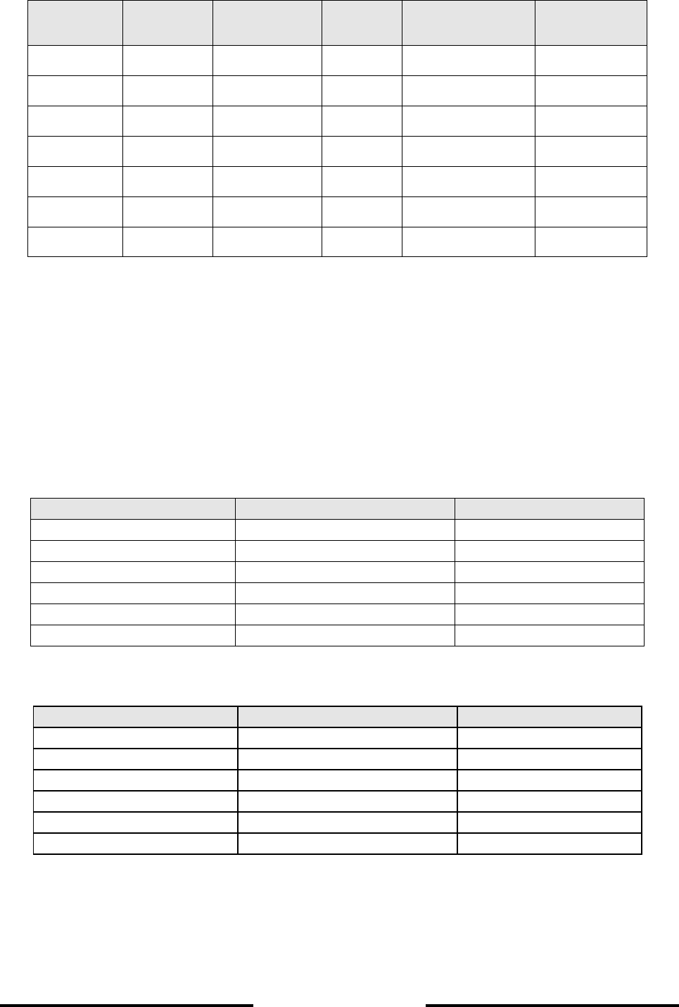
Table of maximum measurable water depth, depending on frequency, transducer type, cable
length.
Transducer
Type
Frequency Manufacturer Electrical
Power
Maximum Cable
Length
Maximum
Waterdepth
LSE 132 30 kHz Elac Nautik 450 Watt 600 m 1200 m
LSE 297 50 kHz Elac Nautik 250 Watt 400 m 600 m
LSE 133 50 kHz Elac Nautik 450 Watt 600 m 1100 m
SW 6016 100 kHz STN Atlas 200 Watt 150 m 300 – 350 m
LSE 148 100 kHz Elac Nautik 450 Watt 200 m 350 – 400 m
LSE 313 200 kHz Elac Nautik 250 Watt 150 m 250 – 300 m
LSE 135 200 kHz Elac Nautik 250 Watt 150 m 250 – 300 m
The depth values can only be reached with limited cable length and an undisturbed
acoustic and electric receiver channel.
For cable length longer than mentioned in the table the electrical power of the echosounder has to
be increased according to manufacturer's release.
Table 1 and 2 show as an example cable loss depending on frequency and cable length and the
corresponding possible depth measurements for the frequencies 50 kHz and 100 kHz.
Table 1: Cable loss for 100 kHz and 50 kHz
Cable length in m Loss in dB at 100 kHz Loss in dB at 50 kHz
50 1.2 0.8
100 2.8 1.7
150 4.5 2.6
200 6.3 3.6
250 8.2 4.6
300 10 5.6
Table 2: Depth measuring performance, cable length- dependent for 100 kHz and 50 kHz
Cable len
g
th in m Depth in m at 100 kHz Depth in m at 50 kHz
50 270 600
100 250 580
150 230 560
200 200 540
250 180 515
300 170 495

Page 2-3
L-3 ELAC Nautik
2.1.2 CABLING, CABLE LOCATION, CABLE SPECIFICATION
Critical point in cabling is the correct handling of the cable screens, especially for the transducer
cable.
The cable screens have to be grounded only at one point: at the echosounder.
In all connection boxes the screens are slide and not connected to ground.
Dismantling has to be as short as possible.
The transducer cable from transducer to the first connection box has to be fed through a steel
protection pipe.
From the first connection box to the echosounder three kinds of cable laying are mandatory
recommended:
• the cable is laid in a steel pipe
• a double-screened cable is used as transducer cable, the inner screen is one-side
connected to the echosounder's ground, the outer screen is one-side connected to the
ship's ground.
• the transducer cable has to be laid separately from other cables in a distance of
minimum 0.5 m.
Most important is not to lay single shielded cable in the vicinity of other cable.
NOTE: in any case shielded cable has to be used over the whole distance from the
transducer to the echosounder. All connection boxes must be metallic.
2.1.3 TRANSDUCER CABLE SPECIFICATION
The cable from the transducer connection box to the echosounder must be approved marine cable
according DIN 89158 or similar, like MGCG 2x1.5.
At least the requirement of a resistance <13 Ω/ km and a capacity of < 150 nF/ km must be fulfilled.
2.1.4 INTERFACES
Printer interface: Standard CENTRONICS parallel interface, cable length: 5 m max.
Serial NMEA input: Input for navigational data and time synchronisation
Serial NMEA output: Water depth and additional information, see chapter 3.5.
Both serial interfaces are RS 422.
Only equipment with RS 422 interfaces can be connected to the echosounder, otherwise the
interface electronic gets damaged.

Page 2-4
L-3 ELAC Nautik
2.1.5 INSTALLATION REPORT; SERVICE REQUEST
After the installation and the quick check ( see chapter 5.1.2) are completed, please fill in the
installation report and send a copy to the ELAC Nautik service center ( FAX +49 431 883 366 ).
The original belongs into the technical handbook.
If service is needed in case of trouble with the echosounder, please complete the service request/
inspection sheet and forward it to the service company responsible with a copy to the ELAC Nautik
service center ( FAX + 49 883 366 ).

Page 2-5
L-3 ELAC Nautik
Installation – Report
Schiffsname
Ship’s name _________________________________________________
Installationsfirma
Installation Company _________________________________________________
Installationsdatum
Date of Installation ______________________________
LAZ 5100 ES 5000 Atlas 9205
Werk-Nr. (S/N) 1-Kanal – Gerät 2-Kanal – Gerät
Serial Number 1-channel unit 2-channel unit
Wandlertyp
Transducer Type S/N
Digitale Tochteranzeige
Digital Display Unit DAZ 25 Atlas 9205 T
S/N S/N
Einstellungen
Settings
LAZ 5100 Kanal 1
Channel 1
Kanal 2
Channel 2
Frequenz / Frequency
Blocking Depth
Draft
Trim
Location
NMEA - Interface
Baudrate
Mode
Repetition Rate
Protocol
Bitte eine Kopie des Installationsreports an Elac Nautik Service Center schicken.
Please forward a copy of the Installation Report to Elac Nautik Service Center.
Fax + 49 431 883 366
Page 2-6
L-3 ELAC Nautik
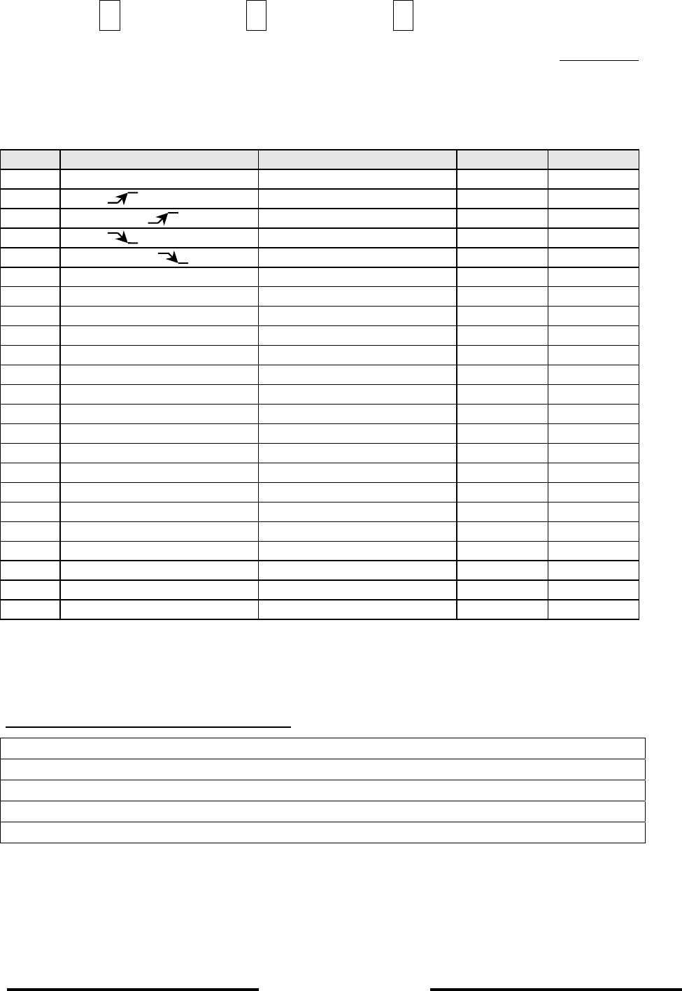
Service – Anforderung / Service Request
LAZ 5100 ES 5000 Atlas 9205 Werk – Nr.
Serial Number
Schiffsname: Schiffsfax:
Ship’s Name: ___________________ Ship’s Fax: _________________________
No. Item Default value Channel 1 Channel 2
1. Menu
„
Alarm“
1.1
A
larm
„
OFF“
1.2
A
larm de
p
th
„
0000“
1.3
A
larm
„
OFF“
1.4
A
larm de
p
th
„
0000“
2. Menu
„
Parameter“
2.1 Sound velocit
y
1500 m/s
2.2 Units m
2.3 De
p
th mode DBK
3. Menu
„
S
y
stem Set U
p
“
3.1 Date
,
Time actual date
,
time
3.2 Service select with
y
es
3.2.1 Channel Settin
g
s
3.2.1.1 Draft 0
,
0 m
3.2.1.2 Trim 0
,
0 m
3.2.1.4 Blockin
g
De
p
th 2 - 2
,
5 m
3.2.1.4 Fre
q
uenc
y
xx kHz
3.2.1.5 Location BOW
,
AFT
3.2.2 Interface
3.2.2.1 External PC 38400
;
8N1
3.2.2.2 NMEA / DAZ 25 4800
;
8N1
3.2.2.3 Re
p
etition Rate Fast / Slow
3.2.2.4 Protocol DPT/DBT or ELAC
Fehlerbeschreibung / Fault Description
Page 3-1
L-3 ELAC Nautik
3 TECHNICAL DESCRIPTION
3.1 GENERAL
The LAZ 5100 Navigation Echosounder is a compact, processor controlled, state of the art system.
Presentation of the water depth is made on a Liquid Crystal COLOR Display (LCD) as.
• depth below the keel (DBK)
Logically structured MENUS assist the user when selecting the operating parameters required.
Built to the highest standards, it is certified to meet all requirements laid down by the
IMO Resolution MSC 74/69: Amendments to Resolution A.224,Annex 4 . Wheelmark-tests are
certified by the German authorty BSH (German Hydrographic Institute)..
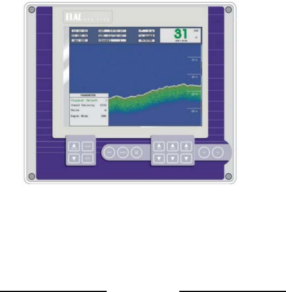
Figure 3-1: LAZ 5100 Display and Control Unit

Page 3-2
L-3 ELAC Nautik
3.2 SYSTEM CONFIGURATION
NOTE: See also Figure 3-2, System Configuration with Options.
The basic system configuration is as follows:
• 1 x Display and Control Unit LAZ 5100
• 1 x Connection Box
• 1 x Transducer
3.2.1 DISPLAY AND CONTROL UNIT
The Display and Control Unit will normally be installed on the bridge, either mounted in a console
or bracket mounted to the deckhead or bulkhead. It is made up of a display area and a keypad
which is used to alter system parameters and settings.
The unit can be a one or two channel unit, working with different transducers on different
frequencies, see Technical Data.
When used with only one transducer ( see Figure 3-1 ), the display area shows the following:
• Water depth
• Range scale
• Time and Date
• Latitude and Longitude (if connected to a Navigation system with a standard
NMEA 0183, version 2.0 interface)
• Minimum and maximum depth alarm settings (if activated)
• A trace of the sea bed
• A colour bar representing the signal strength of the echoes
With two channels, a vertical split display shows left half channel 2 information, right half channel 1
information. Instead of LAT/ LONG a second water depth indication appears.
A built-in ring memory continually stores system data, this allows the user to recall data to the
screen, or print out a hard copy of any or all events occurring within the last 24 operating hours
(if a printer is connected).

Page 3-3
L-3 ELAC Nautik
3.2.2 TRANSDUCER CONNECTION BOX
This will usually be installed near the transducer, to allow a defective transducer to be replaced
without having to replace the complete cabling to the Display and Control Unit. The connection box
must be made of metallic material.
3.2.3 TRANSDUCER
The transducer converts electrical energy to sound energy and transmits this towards the sea bed.
Sound energy returning from the sea bed, in the form of echoes, is converted into electrical energy
by the transducer and fed to the Display and Control Unit for evaluation and presentation.
3.3 OPTIONAL EQUIPMENT
The following optional equipment is available to broaden the system capabilities:
• Digital Slave Display(s)
• Printer
• Connection Box
• Transducer(s)
• Switch box
Page 3-4
L-3 ELAC Nautik
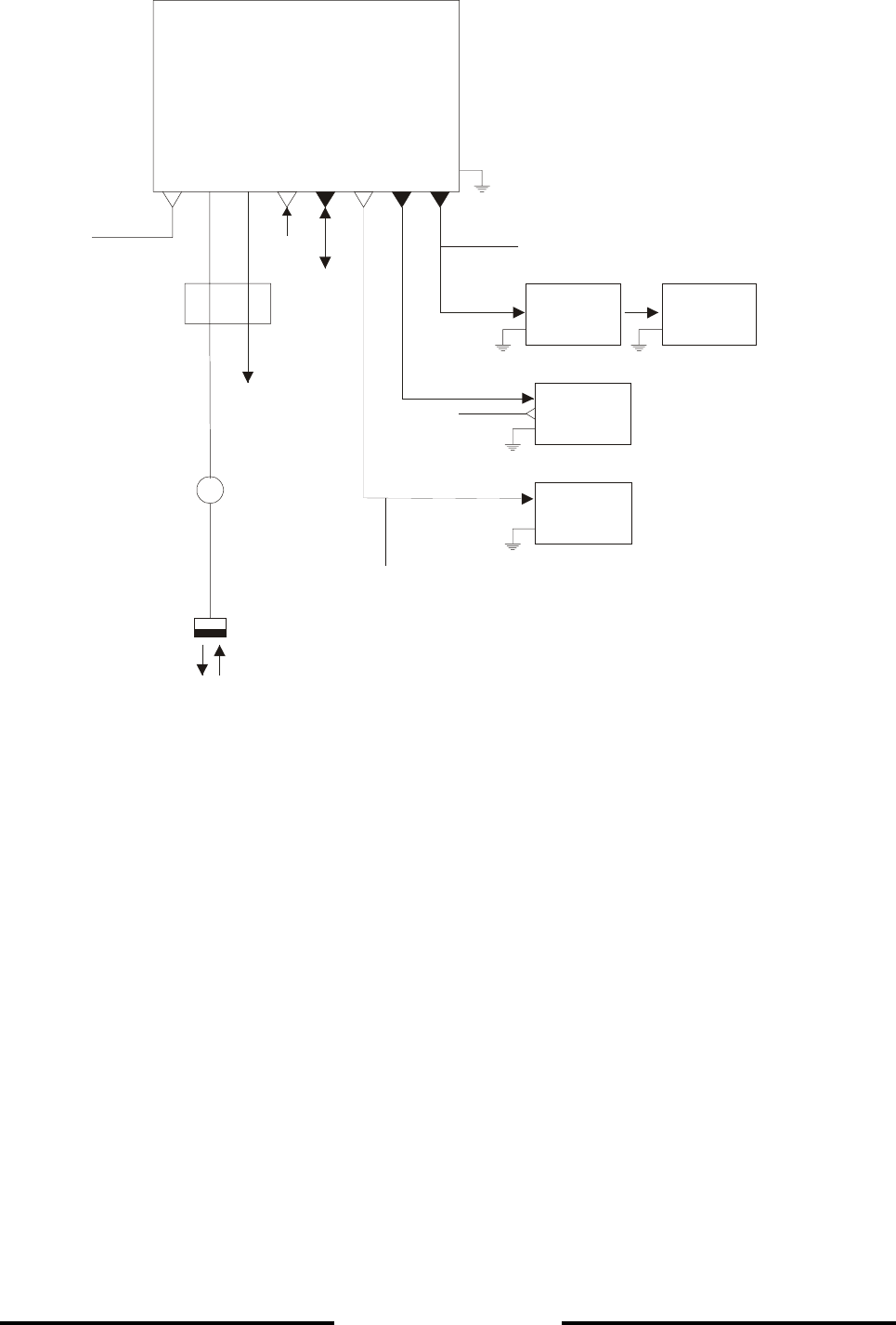
Figure 3-2 : System Block Diagram with Options
* Operator´s Fitness Check
** Mute- Control, TXD1 for Voyage Data Recorder ( NMEA, RS 422)
PRINTER
OPTIONAL
CONNECTION
BOX
N
AVIGATIONS-
ECHO SOUNDER
LAZ 5100
X3 X5X2 X7X1 X6X4 X8
RS 232 RS 422
RS 422
NMEA
CONNECTION BOX
TRANSDUCER
MAINS
MAINS
DAZ 25 DAZ 25
OPTIONAL OPTIONAL
OPTIONAL
OPTIONAL 2nd
TRANSDUCER
OPTIONAL
SWITCH BOX
*
**

Page 3-5
L-3 ELAC Nautik
3.3.1 DIGITAL SLAVE DISPLAY(S)
These are used to repeat water depth information at other parts of the ship where such information
is needed. A total of two Digital Slave Displays can be connected directly to the system.
NOTE: Echosounding Systems and remote indicators which detect and display the
water depth from a single momentary value per transmission pulse, e.g. digital
and pointer displays, can, over a period of time display false readings. This is
primarily valid in shallow water areas. For this reason, water depths displayed
in this manner must be compared with the graphic presentation at regular
intervals in order to guarantee the ship's safety.
IMPORTANT NOTE: While crossing steep slopes the echo evaluation might fail. A steady
depth display cannot be guarantied in this case. The LAZ depth display
will show the last evaluated depth value together with a question mark,
longer lasting errors will be indicated by a question mark without any
depth value. At the digital slave display "----" will be displayed in this
case.
3.3.2 PRINTER
A Printer can be connected to give a continuous hard copy of data presented on the display area
or to print out a hard copy of events from any time within a previous 24 operating hour period.
3.3.3 CONNECTION BOX
The Connection Box is connected up to the Display and Control Unit and provides the following
connections:
• a 2nd Digital Slave Display
• a blanking pulse output
• depth alarm relay contacts (potential free)

Page 3-6
L-3 ELAC Nautik
3.3.4 TRANSDUCER OPTIONS
If a 2 channel module is installed, the system is capable of accommodating two transducers
without further modification, e.g. one fore and one aft, one port and one starboard. Information
received from either or both transducer(s) can be called up for display.
3.3.5 SWITCH BOX
If no 2 channel module is installed, a switch box can be used for the connection of two transducers
of the same type (frequency). Echo-information of the transducer selected by the switch box will be
shown on the display.

Page 3-7
L-3 ELAC Nautik
3.4 TECHNICAL DATA
Supply voltage, nominal : 95 - 240 V AC, 50 - 400 Hz
(min. 85 V AC, max. 264 V AC)
10 - 30 V DC (option, via power pack)
Power consumption : Approx. 25 W
Operating temperature range : -15°C - +55°C
Storage temperature : -20°C - +60°C
Housing : Cast aluminium
Protection code : IP 53
Transducer impedance : 50 - 150 Ohms
Pulse length : 0.3, 1, 3 ms, (automatically switches to suit
range selected)
Measurement ranges : 0 - 10, 20, 50, 200, 500, 2000 m (or the
equivalent in feet or fathoms)
Auto range : depending on the water depth range scale of
200m or 50 m will be selected automatically
Digital Depth Information : 150% of measurement range for 0 - 10m
0 - 50m
120% for other ranges
Resolution : 1% of range selected
Measuring accuracy : 2.5% of depth reading
Display : Liquid Crystal Display,
Display size : 192 mm x 144 mm
Pixels : 640 (hor.) x 480 (vert.)
Minimum sounding depth : 0.5 m or equivalent ( Transducer depended )
Depth corrections Transducer-surface : up to 9.9 m
Starting with software version 1.82 : up to 29,9 m
Transducer-keel : up to 4.9 m
Standard frequencies (kHz) : 28, 30, 33, 38, 50, 100, 200, 210 (selectable)
2 Channel version : any combination of the frequencies above
Output power : 1000 W Max. dependent upon range selected
and transducer installed
Compass Safety Distance : Magnetic compass : 0.5 m
: Steering compass : 0.3 m
Dimensions : Height = 288 mm
Width = 336 mm
Depth = 156 mm
Weight : Approx. 8 kg

Page 3-8
L-3 ELAC Nautik
Deadman alarm : altering parameters of the unit causes an output
to a central alarm unit ( potential free relais
contact )
Power alarm : when the power supply voltages decreases 100
V a visual and audio alarm ( with mute control )
is activated, a potential free output for external
use is available ( potential free relais contact )
.

Page 3-9
L-3 ELAC Nautik
3.4.1 ELECTROMAGNETIC COMPATIBILITY
The LAZ 5100 conforms with specifications laid down in DIN* EN 60945 (IEC945+A1) Navigation
equipment for Shipping; all editions up to March 1997 and also to the newest version 4 with
measurements up to 2 GHz.
A declaration of conformity, in accordance with European Community guideline 89/336/EG, can be
found in Figure 3-4 on page 3-17.
* DIN (Deutsches Institut für Normung) = German Standards Institute
Page 3-10
L-3 ELAC Nautik
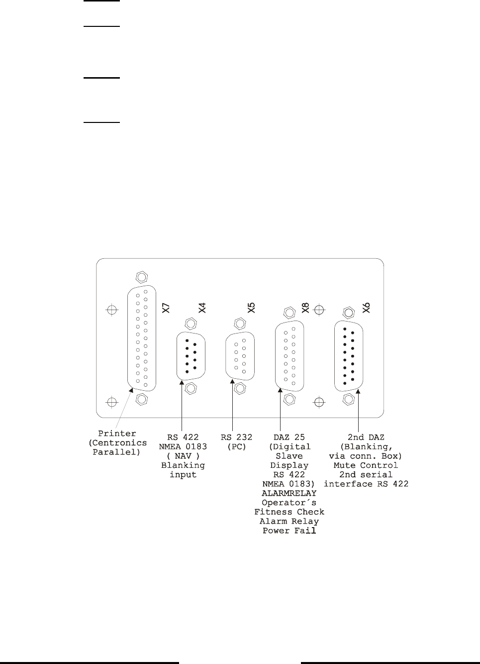
3.5 INTERFACES
The LAZ 5100 has the following interfaces:
• RS 422, NMEA, for Navigation data input (X4), Blanking input
• RS 232, Personal Computer connection for testing (X5)
• Centronics, parallel Printer connection (X7)
• RS 422, Digital Slave Display connection and potential free relay contacts for
alarm ACTIVE (X8), relay control for Operator´s Fitness Check
• RS 422, Power supply for a 2nd Digital Slave Display, and blanking pulse output
(X6), Mute Control input, second serial output for Voyage Data Recorder, Power
Fail output.
• Interface to an external CRT monitor.
Interface connections are made at the rear of the unit. Figure 1-3 below shows which connector
belongs to which interface.
Figure 3-3 : LAZ 5100 Interface Connector Plate
NOTE: For pin connections, see Table 1 at the end of this Chapter.

Page 3-11
L-3 ELAC Nautik
3.5.1 DESCRIPTION OF NMEA INTERFACES
All serial interfaces described in this chapter conform to EN 61162-1 ( 2001 ).
(X4)
A navigation system can be connected to this interface so that the ship's co-ordinates are
displayed by the LAZ 5100. The system will accept and evaluate data sentences in NMEA 0183,
Version 2.30, GLL and ZDA formats, as follows:
GLL Format
Example:
ZDA Format
$--GLL IIII.II,a yyyyy.yy,a hhmmss.ss A hh, , , , * <CR><LF>
Checksum
Status : A =Data Valid
UTC at this position
Longitude, E/W
Latitude, N/S
Talker Identification
$GPGLL 5420.549,N 01007.192,E 201533.25 A 02, , , , * <CR><LF>
Checksum
Data Valid
UTC =20:15:33.25
Longitude=10°07.192’E
Latitude=54°20.549’N
Data are being received from
a Global Positioning System
$--ZDA hhmmss.ss xx,xx,xxxx xx,xx hh,,,*<CR><LF>
Checksum
Difference between UTC and
GMT
Day,Month,Year
UTC
Talker Identification

Page 3-12
L-3 ELAC Nautik
Example:
(X8)
Interface for START/ STOP - SLAVE indicator, potential free alarm relay contacts and Digital Slave
Indicator.
After each sounding the LAZ 5100 transmits depth information to the Digital Slave Display
interface (15 to 60 times per minute, depending upon the measuring range selected) in NMEA,
Version 2.00 format. The DPT (Depth) and DBT (Depth Below Transducer) sentences are as
follows:
DPT (Depth)
$ZAZDA 184533.20 20,12,1995 12,15 62, , , * <CR><LF>
Checksum
Difference 12 hrs 15 mins
Date 20th Dec 1995
UTC=18:45:33.20 s
Data are originating from
an atomic clock
$SDDPT x.x -x.x xx hh, , , ,* <CR><LF
>
Checksum
Distance transducer-keel
in metres
Depth in metres
Range Scale

Page 3-13
L-3 ELAC Nautik
Example:
Depth Below Transducer (DBT)
Example:
$SDDBT x.x,f x.x,M x.x,F hh, , , * <CR><LF>
Checksum
Depth in fathoms
Depth in metres
Depth in feet
$SDDBT 0012.1,f 0003.7,M 0002.0,F 32, , , * <CR><LF>
Checksum
Depth = 2 fathoms
Depth = 3.7 metres
Depth = 12.1 feet
$SDDPT 0337.0 -1.
5
, , ,0500,*4D<CR><LF>
Checksum
Transducer=1.5 metres above
the keel
Depth in metres
Range Scale

Page 3-14
L-3 ELAC Nautik
A NMEA proprietary sentence ELAC is available to allow the transfer of dual channel depth
information, including transducer mounting position.
ELA (Manufacture’s Mnemonic Code)
k: S= Starboard, P= Port, B= Bow, A= Aft, 0=not selected
m: K=DBK (Depth below Keel), S=DBS (Depth below Surface), T=DBT (Depth below
Transducer)
r: Range Scale
q: Quality of digital depth reading:
0=no depth information available
1=no depth information available, poor quality
2=depth information available, high reliability
Example:
To activate the Protocol ELAC see chapter 5.1.2 Initial System Set-up.
$ CSDS, , , , , , ,r,* <CR><LF>Pkx.xd.d-t.tmghh
ELA
Checksum
Depth quality
Selected depth mode
Distande transducer-keel
in metres (TRIM)
Distance transducer-surface
in metres (DRAFT)
Depth in metres
Transducer location
Manufacture´s mnemonic code
P:Propriatary sentence identifier
Range Scale
$ CSDS, , , , , , ,0500,* <CR><LF>P B 0337.0 3.4 -1.5 K 2 3F
EL
A
Checksum
Depth information, high realibility
Depth below keel
TRIM, transducer 1.5 m above keel
DRAFT, transducer 3.4
below surface
Depth = 337.0 m
Depth from Bow transducer
Range Scale

Page 3-15
L-3 ELAC Nautik
3.5.2 OTHER INTERFACES
(X5)
Reserved for service technicians for testing purposes and transferring data to a PC (special
software required).
(X6)
This interface provides a power supply and serial Data output for a second Digital Slave Display
and a blanking pulse output.
(X7)
This Centronics interface allows an EPSON LX 300 (or compatible) printer to be connected to the
system. Max. length of printer cable 5 m !
(X38)
This is an output to connect a standard CRT monitor to the echosounder.

Page 3-16
L-3 ELAC Nautik
NMEA IN PC 2nd DAZ Printer DAZ 25 Monitor
Pin X4 X5 X6 X7 X8 X38
1 CANL*** BSL SioB1Tx- Strobe OFC 1** red
2 SioBRxD+ Sio0RxD SioB1Tx+ Data 0 OFC 2** green
3 n.c. Sio0TxD SioB0Tx+ Data 1 SioB0Tx+ blue
4 Blanking in - n.c. Mute in b Data 2 n.c. n.c.
5 Blanking in + Ground Mute in a Data 3 Alarm A ** Ground
6 CANH*** n.c. SioATxD+ Data 4 START Ground
7 SioBRxD- n.c. SioARxD+ Data 5 STOP Ground
8 n.c. n.c. SioB0Tx- Data 6 SioB0Tx- Ground
9 n.c. Vcc Blanking out -* Data 7 Alarm B ** n.c.
10 --- --- Blanking out +* ACK Alarm C ** Ground
11 --- --- Aux. Voltage + BUSY Aux. Voltage + n.c.
12 --- --- RSRemote PAPER END Power Fail 1** n.c.
13 --- --- SioATxD- SELECT Power Fail 2** hsync
14 --- --- SioARxD- n.c. LSE2+2 vsync
15 --- --- Aux. Voltage - ERROR Aux. Voltage - n.c.
16 --- --- --- RESET --- ---
17 --- --- --- n.c. --- ---
18 --- --- --- Ground --- ---
19 --- --- --- Ground --- ---
20 --- --- --- Ground --- ---
21 --- --- --- Ground --- ---
22 --- --- --- Ground --- ---
23 --- --- --- Ground --- ---
24 --- --- --- Ground --- ---
25 --- --- --- Ground --- ---
Pin Connections
LEGEND: nc = not connected OFC: Operator Fitness Check
--- = not available
* Blanking + : open Collector (Potentialfree Transistor output )
Blanking - : open Emitter
** Relays; Contact rating : Umax 28 VDC, Imax 1 A
Max. switching Power: 5W
*** Not in use

Page 3-17
L-3 ELAC Nautik
EC- Approval
Figure 3-4 : Copy of the Original Declaration of Conformity
Page 4-1
L-3 ELAC Nautik
4 OPERATING INSTRUCTIONS
4.1 SWITCHING THE SYSTEM ON/OFF
CURSOR GAIN RANGE DIM
ESCAPE
ENTER
PRINT MARKER
ONOFF
To switch the System ON, press the far right-hand key marked "ON". The system will switch ON
and assume the parameter settings which were selected when the system was last switched OFF.
To switch the system OFF, press and hold the second key from the right, marked "OFF", the
system will switch OFF after about 3 to 5 seconds. This is a built-in safety feature to prevent
accidental switching OFF.
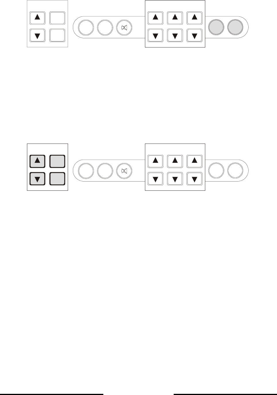
4.2 BRIEF EXPLANATION OF CONTROLS
CURSOR
GAIN RANGE DIM
ESCAPE
ENTER
PRINT MARKER
ONOFF
• CURSOR : The CURSOR keys allow the user to move the cursor within a MENU and alter
parameters. The position of the cursor can easily be seen, the word, letter or
digit marked by the cursor appears inverse (dark background, light text).
Parameters to be altered must first be "marked" by the cursor.
• ESCAPE : The ESCAPE key is used to leave a MENU or to abort parameter alterations.
• ENTER : The ENTER key is used to call up MENUS and confirm parameter alterations
within MENUS.
Page 4-2
L-3 ELAC Nautik
CURSOR
GAIN RANGE DIM
ESCAPE
ENTER
PRINT MARKER
ONOFF
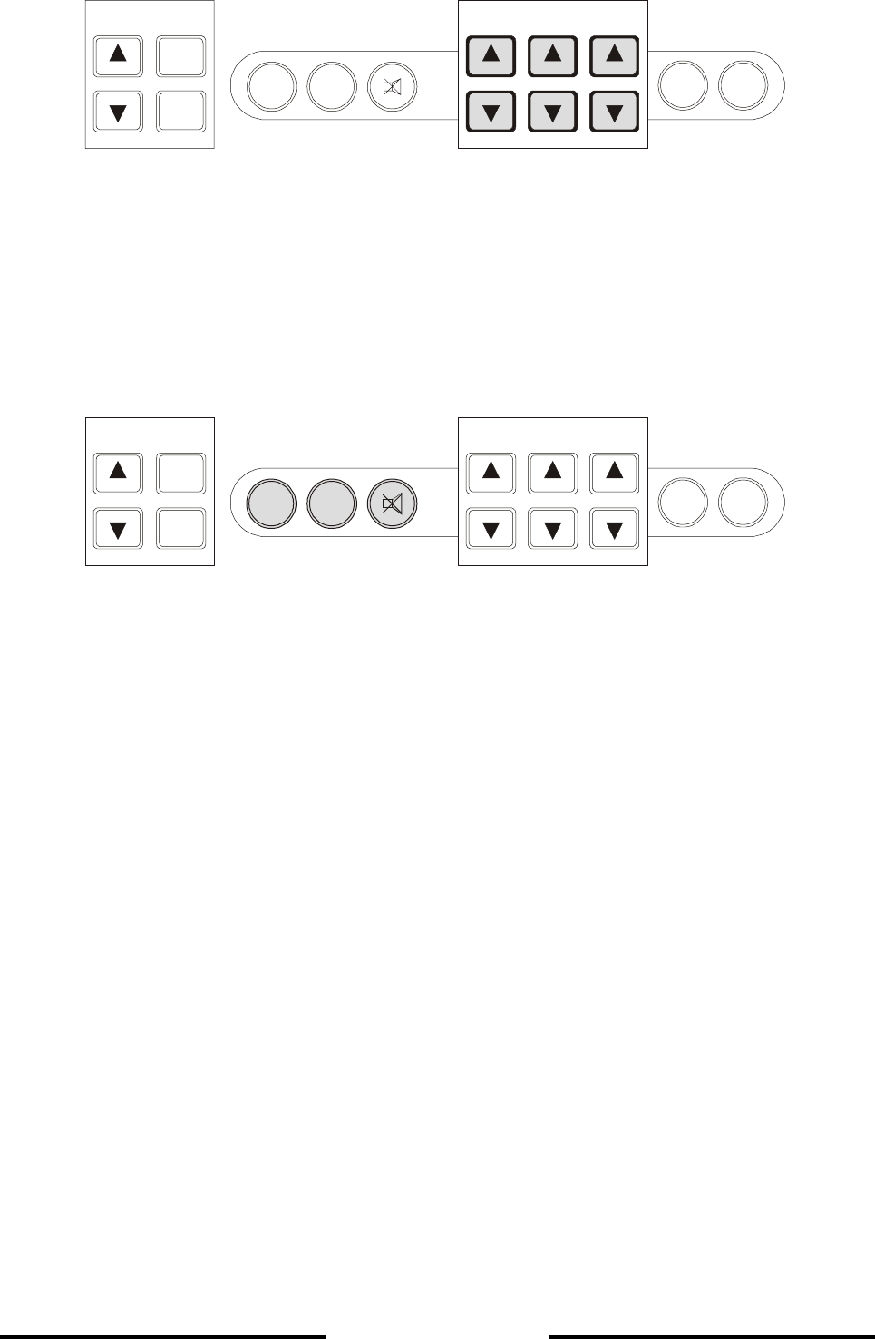
• GAIN : The GAIN keys are used to alter the system gain, otherwise known as
amplification, to achieve a clearer presentation. The system can be operated
with either automatic or manual gain control. See chapter 4.4.1.
• RANGE : The RANGE keys are used to set the depth range of the system.
• DIM : The DIM keys are used to set the display backlighting level to suit the user.
CURSOR GAIN RANGE DIM
ESCAPE
ENTER
ONOFF
PRINT MARKER
• PRINT : The PRINT key is used when the user wishes to make a simultaneous hard copy
of the echogram. This is only possible if a printer is connected to the system.
• MARKER : When the MARKER key is pressed, a vertical dotted line appears on the screen
and moves with the presentation from right to left. At the same time all relevant
information is stored in the system's 24 hour memory. This memory stores data
from the previous 24 system operating hours.
• SYMBOL : The key marked with a loudspeaker symbol is used to acknowledge acoustic
depth alarms.

Page 4-3
L-3 ELAC Nautik
4.3 DISPLAY AREA
4.3.1 SINGLE CHANNEL DISPLAY
The Display Area is used to present the user with all relevant information. The screen is divided
into two areas. The lower, main area is used to present an echogram of the scenario beneath the
ship. It is provided with a scale and time markings. The range in use is displayed beside the scale
markings, at the bottom right of the screen. The time markings appear at 3 minute intervals at the
bottom edge of the screen. As explained previously, when MENUS are called up, they will appear
at the bottom left-hand side of this area. The smaller strip across the top of the screen provides the
user with various system and depth information (see illustration below).
Explanation of information contained in the illustration above (from left to right):
TIME : Shows the actual time
DATE : Shows the actual date
NAV OFF : Flashes to indicate that the Navigation mode is not in use i.e. the user has
selected other units, sound velocity or depth mode. When the user returns to
the Navigation mode,
by selecting NAV Defaults, this window will disappear (see also chapter 4.5.1,
NAV-Defaults). If the echosounder is in the two channel mode ( only if the
second channel and a second transducer is fitted), NAV - OFF is activated
without flashing.
LONGITUDE : These windows will display the actual Lat. and
LATITUDE : Lon. only if the system is connected up to the ship's navigation system.
Printing : This window is usually blank. If the user chooses to make a hard copy of the
echogram, by pressing the PRINTER key (a printer must be connected)
the word "Printing" will appear here.
ALARM : These windows show the depth alarm settings. The upper window shows the
minimum depth alarm, the lower window shows the maximum depth alarm. If
the alarms are not activated, e.g. Status = OFF, the relevant window(s) will
remain blank. If an alarm condition is present, the relevant window will flash
mm

Page 4-4
L-3 ELAC Nautik
REPLAY : When the user chooses to display information stored over the previous 24
operating hours (using the LOG DATA MENU), the word "REPLAY" will
appear here.
The large window at the right-hand side of the information area is used to display the actual water
depth, the measurement mode, units of measurement. The measurement mode can be either:
• Depth Below the Keel = DBK (as shown)
• Depth Below the Surface = DBS
• Depth Below the Transducer = DBT
The units of measurement can be either:
• Metres = m (as shown)
• Feet = ft
• Fathoms = ftm
If instead of the depth value a ? appears, make sure, that the echo signal will be in the range
selected.
IMPORTANT NOTE: While crossing steep slopes the echo evaluation might fail. A steady
depth display cannot be guarantied in this case. The LAZ depth display
will show the last evaluated depth value together with a question mark,
longer lasting errors will be indicated by a question mark without any
depth value. At the digital slave display "----" will be displayed in this
case.
Page 4-5
L-3 ELAC Nautik
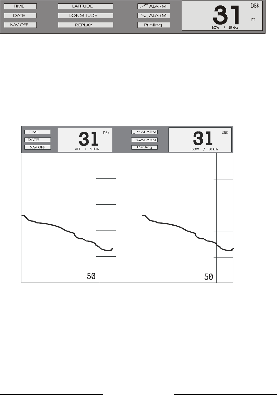
4.3.2 2 CHANNEL DISPLAY
In the 2 channel mode information of the transducer location and frequency of the transducer in
use is added.
If the presentation channel 1/2 is selected, Information of both channels are shown in a vertical
split display.
The indication NAV OFF is activated without flashing to indicate, that all parameters are mode of
presentation is non standard. For each transducer depth location and frequency is shown.
For transducer location and frequency see chapter 5.1.2 Initial System Set - up.
40
10
20
20
40
10
20
20
m
m

Page 4-6
L-3 ELAC Nautik
4.3.3 WARNING FIELDS
Three warning fields are provided on the display:
• NAV OFF flashing indicates that one or more parameters do not correspond to the
navigational mode, i.e. the user has selected other units, sound velocity or depth
mode.
• NAV OFF whithout flashing appears in the 2 channel mode. It is a hint, that in this
display mode the user has to observe, that for instances dedicated digital slave
repeaters are in use.
• POWER ERROR occurs when the supply voltage of the echosounder unit
undergoes a value of 100 V AC. This is an internal alarm, the POWER ERROR field
flashes and an acoustic alarm ( with mute control ) is activated.

Page 4-7
L-3 ELAC Nautik
4.4 ALTERING SYSTEM PARAMETERS AND SETTINGS
When the system is switched OFF, parameters selected are stored in the system's memory. When
the system is switched ON again, these parameters will be retrieved and used (see NOTE below).
NOTE: The "DIM" setting is not stored, a pre-set default setting is used when the
system is switched ON. With two channel systems, channel 1 is the default
channel at start-up.
4.4.1 GAIN, RANGE AND DIM SETTINGS
GAIN (amplification), RANGE (depth range) and DIM (display area backlighting and keypad
illumination) settings are made by pressing the relevant keys. There are two keys for each setting,
one marked with an arrow pointing upwards and one marked with an arrow pointing downwards.
Pressing these keys as described below will alter the present setting. The new setting will appear
briefly on the display area directly above the key which was pressed and the effects of a change
can be observed directly on the display area. Pressing the key a second time will alter the setting
by a further unit.
GAIN:
The unit is fitted with an automatic gain control circuit for the data processing which is always
activated when the unit is switched on. The GAIN setting only influences the displayed echo
information. The GAIN value can be altered between 1 and 10, whereby 1 is the lowest and 10 the
highest gain (amplification) factor.
If the sea bed trace appears too weak, the GAIN level must be increased to give a clear
presentation. If there is a lot of "noise" to be seen on the display area, the GAIN level must be
decreased. To increase the GAIN level, press the GAIN key V To decrease the GAIN level,
press the GAIN key W. The value set will appear on the display area above the key (between 1
and 10). Pressing the same key a second time will cause the value to increase or decrease by one
further unit. Repeat the procedure until a satisfactory sea bed trace is achieved.
In some cases it can be useful to work with manual instead of automatic gain. Manual gain setting
is explained in chapter 4.5.2.

Page 4-8
L-3 ELAC Nautik
RANGE:
The RANGE can be set to suit the circumstances e.g. if a water depth of 35 m is indicated, the
50m range will give a better resolution and accuracy than the 200 m range. The range can be
altered in the same way as the gain, except that here, pressing the RANGE key V will decrease
the range and pressing the RANGE key W will increase the range. There are 6 ranges to choose
from, 10, 20, 50, 200, 500 and 2000 m (or the equivalent in fathoms or feet). Selecting the unit of
measurement is described in chapter 4.5.2.
Increasing the range to more than 2000 m scale an "A" will appear together with the 200 m scale.
"A" indicates the selection of the automaticc mode. When the water depth decreases the range will
at depth less than 50 m switch automatically in the 50 m range scale, if the depth increases, the
200 m range will be selected. Pressing in the automatic mode the range keys, manual control is
activated.
NOTE: When DBS is used, the ranges 0-10 m; 0-20 m are not available, only 0-50 m.
DIM:
The display backlighting can be set in 10 steps to suit the ambient light. To increase the display
backlighting, press the DIM key V. To decrease the display backlighting, press the DIM key W
(see NOTE below).
All other parameters and settings are altered within so called MENUS, as described in chapters
4.4.2 and 4.5.

Page 4-9
L-3 ELAC Nautik
4.4.2 GENERAL INFORMATION REGARDING MENUS
The ENTER key is used to call up the various MENUS in sequence. The order in which they
appear is as follows:
• Press the ENTER key 1x - ALARM MENU
• Press the ENTER key 2x - PARAMETER MENU
• Press the ENTER key 3x - LOG DATA MENU
• Press the ENTER key 4x - SYSTEM SET-UP MENU
If the ENTER key is pressed 5x, the ALARM MENU will re-appear.
When a MENU is called up, the title will be highlighted i.e. it will appear in inverse text, this means
light text on a dark background or vice versa, depending upon the DIM setting. During daylight use,
the text will be light on a dark background and during darkness, when the screen is dimmed, the
text will be dark on a light background.
When the title line of a MENU is highlighted, it is possible to leave that MENU by pressing the
ESCAPE key 1x, or to change to another MENU by pressing the ENTER key 1x or more until the
desired MENU appears. If parameters or settings have been altered within a MENU, the ESCAPE
key may have to be pressed more than 1x in order to either return to the title line or to leave the
MENU completely. The ESCAPE key can also be used to abort parameter selections.
A detailed example of altering system settings and parameters within a MENU can be seen in
chapter 4.4.3. It is advisable that the user reads this Section thoroughly and practices making the
alterations described in order to become more familiar with the system.
WARNING: Do not alter parameters within the SERVICE SUB-MENU unless authorised to
do so. See also WARNING given in chapter 4.5.4, "The SYSTEM SET-UP
MENU".
Page 4-10
L-3 ELAC Nautik
4.4.3 ALTERING SYSTEM SETTINGS/PARAMETERS WITHIN A MENU
When a MENU is called up, it will appear at the bottom left-hand side of the display area. There
are 4 main MENUS available. These can be called up by pressing the ENTER key.
Example: The user wishes to change the MINIMUM DEPTH ALARM from 30m to 20m and
activate it (Status = ON) and to change the MAXIMUM DEPTH ALARM to 410m
and activate it.
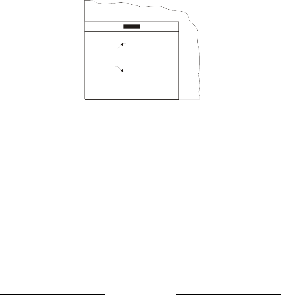
Press the ENTER key once to call up the ALARM MENU. The ALARM MENU as shown below,
appears at the bottom left-hand side of the display area.
The word ALARM is marked by the so called cursor and appears inverse, i.e. dark background,
light text.
In order to alter the MINIMUM DEPTH ALARM setting within this MENU, the value to be altered
must be marked by the cursor. This is done by using the CURSOR keys. The CURSOR key with
the arrow pointing downwards (W) is used to move the cursor down and the CURSOR key with the
arrow pointing upwards (V) is used to move the cursor up. Press the CURSOR W key twice to
mark the word "Depth".
The MENU below shows that the cursor has been moved down to mark the word "Depth" which
now appears inverse.
NAV-Defaults >>
Alarm
Depth 0030
Status OFF
Alarm
Depth 1990
Status OFF
Test Alarm
ALARM
Page 4-11
L-3 ELAC Nautik
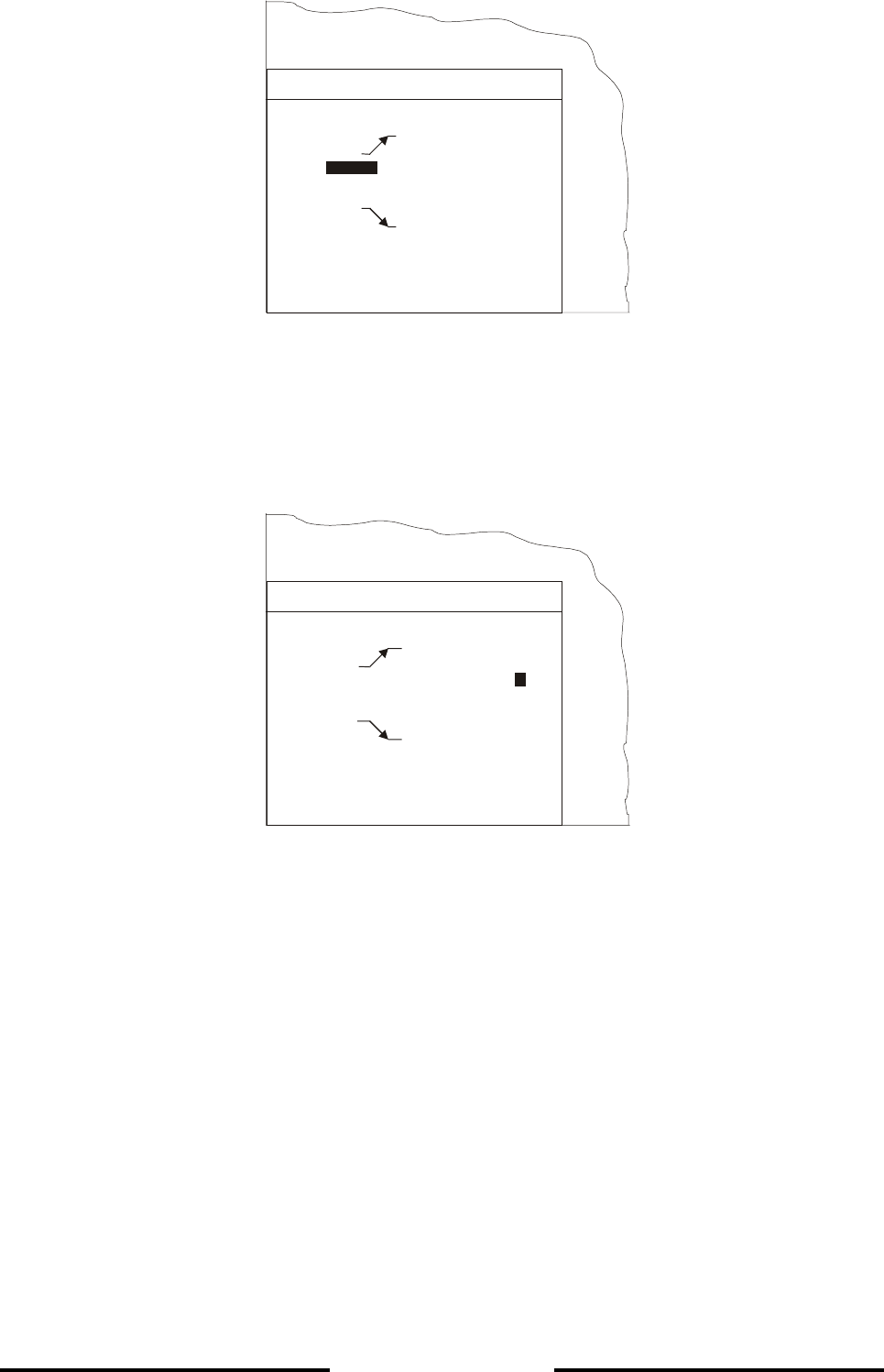
Now press the ENTER key. The cursor will jump from the word "Depth" to the first digit of the alarm
setting, in this case a zero. Press the ENTER key twice more and the cursor will move to the right
and mark the figure 3, as shown in the MENU below.
Press the CURSOR W key once. The figure 3 will change to a 2.
Press the ENTER key to confirm the new setting. The cursor will jump one digit to the right. Press
the ENTER key once more and the cursor will move to mark the word "Status" as shown in the
MENU overleaf.
NAV-Defaults >>
Alarm
Depth 0030
Status OFF
Alarm
Depth 1990
Status OFF
Test Alarm
ALARM
Depth
NAV-Defaults >>
Alarm
Depth 0030
Status OFF
Alarm
Depth 1990
Status OFF
Test Alarm
ALARM
3
Page 4-12
L-3 ELAC Nautik
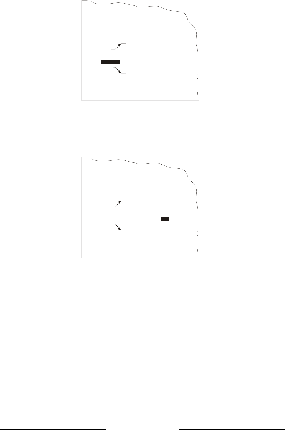
Press the ENTER key and the cursor will jump to the word "OFF". Press a CURSOR key
(V or W) to toggle from OFF to ON. The MENU will appear as below.
Press the ENTER key to confirm the setting. The cursor will jump to the word "Depth" as shown in
the MENU below.
NAV-Defaults >>
Alarm
Depth 0020
Status OFF
Alarm
Depth 1990
Status OFF
Test Alarm
ALARM
Status
NAV-Defaults >>
Alarm
Depth 0020
Status
Alarm
Depth 1990
Status OFF
Test Alarm
ALARM
ON
Page 4-13
L-3 ELAC Nautik
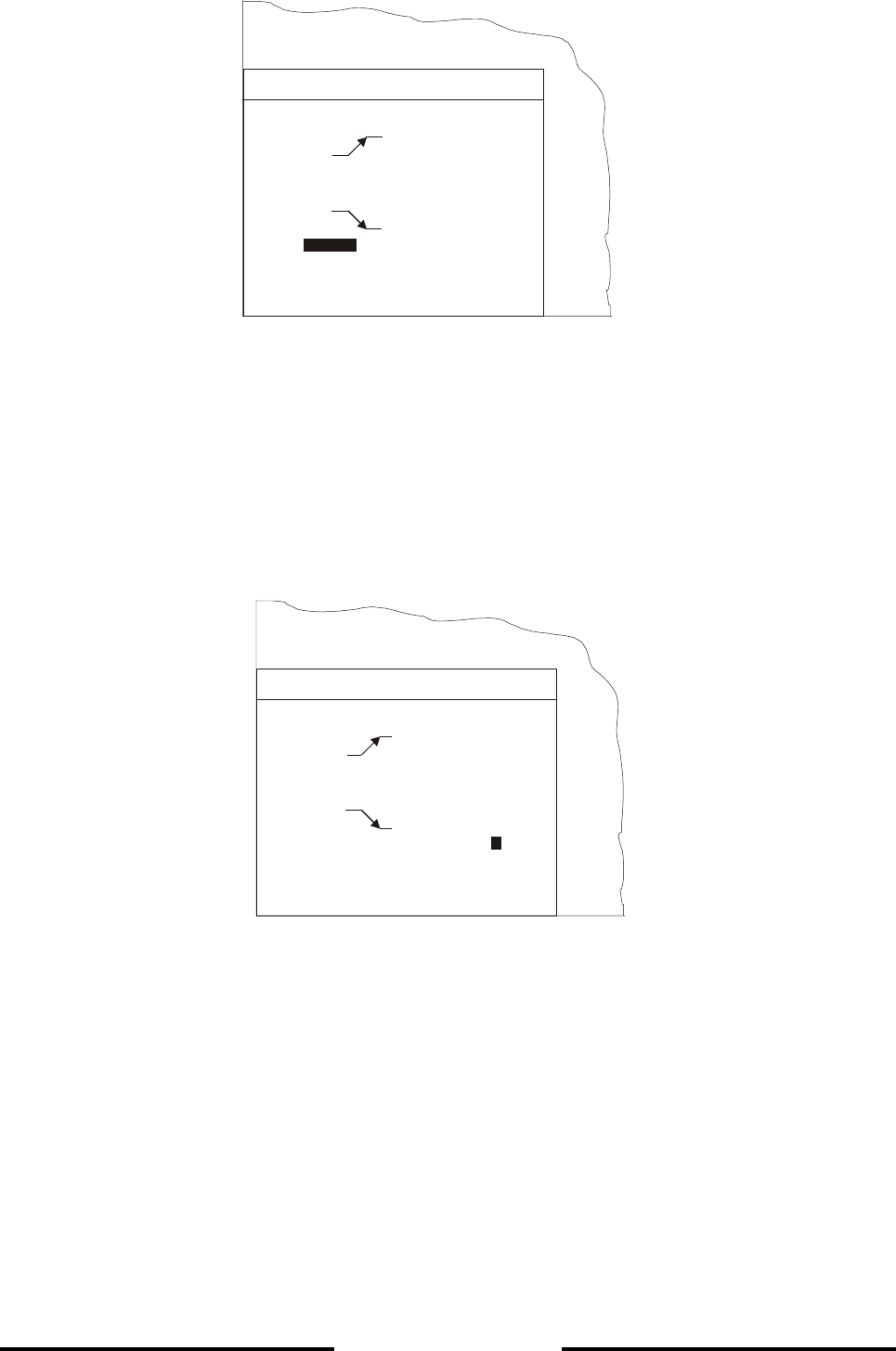
Press the ENTER key and the cursor will jump to the first digit of the alarm setting, in this case a 1,
as shown in the MENU below.
Change the 1 to a 0 by pressing the CURSOR W key. Press the ENTER key to confirm. The cursor
will jump to the next digit, a 9. Repeatedly press the CURSOR W key until the desired value is
reached, in this case a 6. Press the ENTER key to confirm. The cursor will jump to the next digit,
again a 9. Set this to 1 using the CURSOR W key. Press the ENTER key to confirm, the cursor
jumps to the 0 which need not be altered. Now that the desired value, 410m, has been set, press
the ENTER key to confirm. The cursor will jump to the word "Status" as shown in the MENU below.
NAV-Defaults >>
Alarm
Depth 0020
Status ON
Alarm
Depth 1990
Status OFF
Test Alarm
ALARM
Depth
NAV-Defaults >>
Alarm
Depth 0020
Status
Alarm
Depth 990
Status OFF
Test Alarm
ALARM
ON
1

Page 4-14
L-3 ELAC Nautik
Press the ENTER key and the cursor will jump to the word "OFF".
The MENU will appear as shown overleaf.
NAV-Defaults >>
Alarm
Depth 0020
Status ON
Alarm
Depth 0610
Status OFF
Test Alarm
ALARM
Page 4-15
L-3 ELAC Nautik
Alter the Status to ON as described for the minimum depth alarm. Press the ENTER key to
confirm. The cursor will jump to the words "Test Alarm", as shown in the MENU below.
A functional test of the audio/visual alarm can now be carried out by pressing the ENTER key. The
audio alarm must sound and the field(s) showing the alarm setting(s) on the display area must
blink.
Now that the settings have been altered and the alarm tested by pressing the ENTER key, leave
the MENU by pressing the ESCAPE key twice.
NAV-Defaults >>
Alarm
Depth 0020
Status ON
Alarm
Depth 0610
Status
Test Alarm
ALARM
OFF
NAV-Defaults >>
Alarm
Depth 0020
Status ON
Alarm
Depth 0610
Status
ALARM
OFF
Test Alarm

Page 4-16
L-3 ELAC Nautik
4.5 MENU DESCRIPTION
4.5.1 THE ALARM MENU
To call up the ALARM MENU, press the ENTER key once.
This MENU is used to set, select or test the following:
• Select NAV-Defaults
• Set Minimum Depth Alarm
• Set Maximum Depth Alarm
• Test the Alarm system
NAV-Defaults
NAV(Navigation)-Defaults are basic compulsory settings which must be used when operating the
system for navigational purposes. These are laid down by the International Maritime Organisation
(IMO) and state that:
• The system must operate with one channel only
• The sound velocity must be set to 1500 m/s
• The unit of measurement must be metric (metres)
• Water depth must be measured below the keel (DBK)
If the system is being operated in any other mode, e.g. units selected are feet, water depth from
the surface is selected etc. the user can return to the NAV mode by calling up this MENU and
selecting NAV-Defaults. A sub menu will appear in which the user can choose between selecting
NAV-Defaults, or returning to the ALARM MENU. The sub menu can be seen overleaf.
NAV-Defaults >>
Alarm
Depth 0020 (0....1999m)
Status ON (ON, OFF)
Alarm
Depth 0410 (0....1999m)
Status ON (ON, OFF)
Test Alarm
ALARM

Page 4-17
L-3 ELAC Nautik
This function will
set the sounder
to NAV-Defaults !
Continue ? NO (NO, YES)
WARNING!
To set the system back to NAV defaults, call up the ALARM MENU and press the following keys:
• CURSOR W (1x, to mark NAV-Defaults)
• ENTER (1x, to call up SUB-MENU)
• CURSOR W or V (to select YES)
• ENTER (to confirm selection and exit SUB-MENU)
• ESCAPE (1x, to leave the MENU)
Maximum and Minimum Depth Alarms
The user can set the system alarm so that an audio/visual alarm occurs if the water becomes
shallower than a set minimum or if the water becomes deeper than a set maximum. This depth is
always measured from the ship's keel. An Alarm Test facility is available so that the alarm function
can be periodically tested. These settings are made as described in chapter 4.4.3.
Mute- Control
The audio alarm can be muted externally by connected Mute Control.

Page 4-18
L-3 ELAC Nautik
4.5.2 THE PARAMETER MENU
To call up the PARAMETER MENU, press the ENTER key twice.
Channel Select 1 (1, 2, 1/2)
Sound Velocity 1500 (1400....1699)
Units m (m, ftm, ft)
Depth Mode DBK (DBK, DBT, DBS)
(Auto, Man)Gain auto
PARAMETER
The PARAMETER MENU is used to select system parameters which vary from those laid down by
the IMO. The following and settings can be made within this MENU:
• Channel selection
• Sound velocity setting
• Unit of measurement selection
• Depth mode selection
Channel Select
The Channel Select function is only operative if the system is fitted with two transducers. When the
system is switched on, channel 1 is the default setting. This function is used to select the channel
to be presented on the display area. Presentation of either Channel 1, Channel 2, or both is
possible. If both channels are selected, they will appear side by side on the display area,
Channel 1 to the right and Channel 2 to the left. Call up the PARAMETERS MENU and press the
following keys to make a selection:
• CURSOR W (1x, to mark Channel Select)
• ENTER (1x, to mark Channel number)
• CURSOR V or W (to make selection)
• ENTER (1x, to confirm selection)
• ESCAPE (2x, to leave the MENU)

Page 4-19
L-3 ELAC Nautik
Sound Velocity
Sound travels at varying speeds in water, depending upon the salinity, temperature and density.
The standard NAV(Navigation) default setting for sound velocity is 1500 m/s. If a sound velocity
measuring system is available and the user wishes to adjust the sound velocity of the depth
sounder, call up the PARAMETERS MENU and press the following keys:
• CURSOR W (2x, to mark Sound Velocity)
• ENTER (1x, to mark 2nd digit)
• CURSOR V or W (to alter 2nd digit)
• ENTER (1x, to confirm selection and jump to 3rd digit)
• CURSOR V or W (to alter 3rd digit)
• ENTER (1x, to confirm selection and jump to 4th digit)
• CURSOR V or W (to alter 4th digit)
• ENTER (1x, to confirm selection)
• ESCAPE (2x, to leave the MENU)
Units
The standard default unit of measurement is metres. It is however possible, if the user wishes, to
choose either fathoms or feet. In order to alter the unit of measurement, call up the PARAMETERS
MENU and press the following keys:
• CURSOR W (3x, to mark the word Units)
• ENTER (1x to mark units selected)
• CURSOR V or W (to make selection)
• ENTER (1x, to confirm selection)
• ESCAPE (2x, to leave the MENU)
Depth mode
The standard default depth measurement mode is DBK (depth below the keel). It is however
possible to change this mode to either DBT (depth below the transducer) or DBS (depth below the
surface). In order to alter the mode of depth measurement, call up the PARAMETERS MENU and
press the following keys:

Page 4-20
L-3 ELAC Nautik
• CURSOR W (4x, to mark Depth Mode)
• ENTER (1x, to mark the mode selected)
• CURSOR V or W (to make selection)
• ENTER (1x, to confirm selection)
• ESCAPE (2x, to leave the MENU)
NOTE: When the NAV-Defaults are selected within the ALARM MENU, the system
returns to the navigation mode, using the default values , i.e.:
• Channel Select = 1
• Sound Velocity = 1500 (m/s)
• Units = m
• Depth Mode = DBK
Manual Gain setting
In a noisy environment or if the bottom depth changes very rapidly it is useful to work with manual
gain instead of automatic gain.
The manual mode is selected as follows:
Select second menu (PARAMETER) by pressing ENTER, ENTER
Select in the PARAMETER menu Gain using the cursor, ENTER
With the cursor change Auto to Man., ENTER
With the GAIN keys now gain is adjustable.
With GAIN UP or DOWN gain can be set between 1 (minimum) and 15 (maximum)
Vary the gain value until the bottom is clearly indicated on the display. For differentiation the gain
value selected is shown inverse on the display during the use of the gain keys:
Indication with Auto:
Indication with Man.:
NOTE : During switch off the last gain value in use is stored. If the unit is switched on
again, Auto mode is selected. If Man. becomes selected as described, the
stored last gain value will be recalled.
12
9

Page 4-21
L-3 ELAC Nautik
4.5.3 THE LOG DATA MENU
To call up the LOG DATA MENU, press the ENTER key three times. The MENU as shown below
will appear.
View Display memory contents
Data Transfer >> Transfer data to an external PC
LOG DATA
The LOG DATA MENU is used to gain access to data stored in the system's built-in 24 hour ring
memory. This data can then be viewed on the display area and printed out in full or in part (if an
external printer is connected). The contents of the memory can also be transferred to a personal
computer for further analysis (special software is required in order to transfer and analyse data).
WARNING: During this mode, the echo sounder is not in operation and no actual depth
data will be given. ALARM functions will not be in effect. No data will be
stored.
Page 4-22
L-3 ELAC Nautik
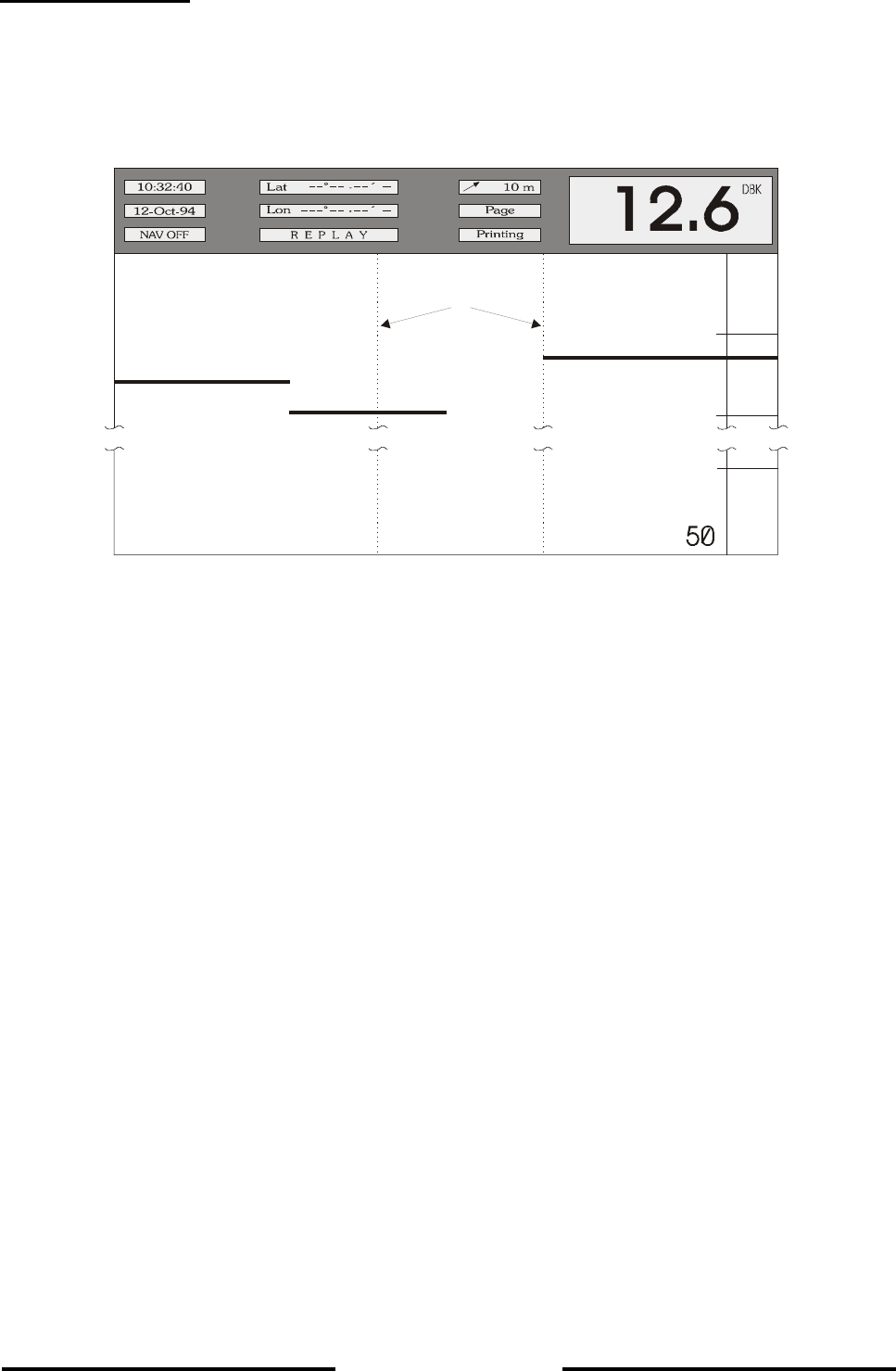
To view stored data
Call up the LOG DATA MENU as described previously. Press the CURSOR W key once to mark
the word "VIEW", followed by the ENTER key. The MENU will disappear from the screen and
stored data will appear. A typical Viewed Data display area can be seen below.
10
20
40
Marker Lines
m
The upper part of the display area contains the following information which is always related to the
1st data block on the extreme right of the display area:
• Time (10:32:40) and date (12-Oct.-94) of stored data
• NAV Mode ON or OFF (if the NAV mode was ON when data was stored, this
window will not be present)
• Latitude and Longitude (only if the system was connected to an external navigation
system)
• The window showing REPLAY indicates that stored data is being viewed
• Depth setting of the shallow water alarm (10m) (if this function was selected)
• Depth, unit (m) and mode (DBK) of measurement
• Depth range (50m)
• the "Page" and "Printing" windows will be explained later
Page 4-23
L-3 ELAC Nautik
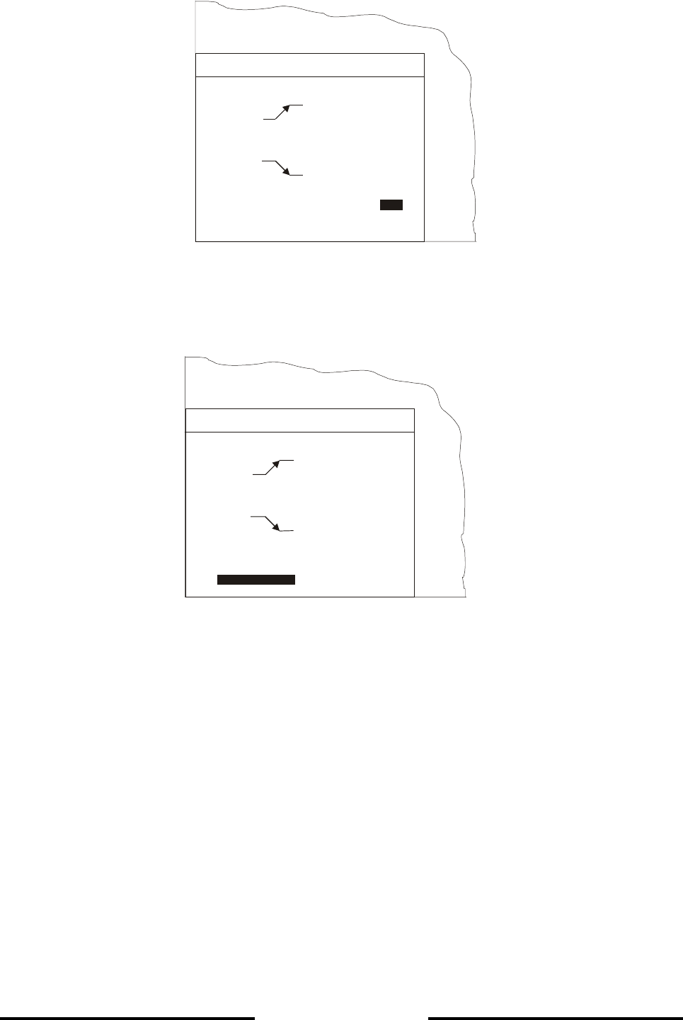
Explanation of controls for viewing data
40
10
20
30
Marker line a
Marker line b
direction A
Reference line for information and
setting print out time period limits
direction B
m
Key Function
CURSOR V
CURSOR W
ENTER
MARKER
PRINT
ESCAPE
Scrolls forwards in time (direction A)
Scrolls backwards in time (direction B)
Toggles page scroll option (for faster scrolling)
Marks one limit of the time period to be printed out (start
or finish)
Marks the other limit of the time period to be printed out
and simultaneously activates the printer (if connected)
Exit, return to the echosounding mode
Controls for Viewing Data
NOTE: With the exception of the DIM and OFF keys, all other keys are inoperative.

Page 4-24
L-3 ELAC Nautik
Scrolling through memory data
To scroll the display to a certain time in the memory at which events that occurred earlier (relative
to time shown in "time" window) wish to be viewed, press and hold the CURSOR W key until
nearing the desired time (shown in the "time" window). Finely adjust the desired time by pressing
the CURSOR V or W key momentarily, each time a key is pressed, the time will advance by a 5
second period. If the event to be viewed occurred a lot earlier, scrolling can be accelerated by
using the "Page scroll" option. Press the ENTER key and the word "Page" will appear in the
window beneath the "Depth Alarm" window. When the CURSOR V or W keys are now pressed
momentarily, the display will be shifted by approx. three quarters of a page backwards or forwards
(pressing and holding these keys scrolls continuously).
EXAMPLE:
To view data at the time "Marker line a" was set, press and hold the CURSOR W key until the
marker line is almost at the right-hand side of the display area. Finely adjust by pressing the
CURSOR W repeatedly until the marker is at the extreme right-hand side of the display area. The
data will now be presented in the upper part of the display area. To move "Marker line b", press the
ENTER key. The word "Page" will appear in the window below the alarm window showing that the
"Page scroll" option is activated. When the CURSOR W is now pressed once, the marker line will
jump to the right. Press the ENTER key to return to the "slow scroll" option and finely adjust as
previously described for "Marker line a".
NOTE: Depth, scale and position information will not be updated during scrolling
(only time and echograms) except when a marker line passes the right-hand
border of the display area.
The following information can be read off the display area for any given time during the previous 24
system operating hours:
• Water depth at that time
• Units and mode of measurement at that time
• Range in use at that time
• Time and date at which the information was stored
• Whether the NAVIGATION mode was in use at that time
• Latitude and Longitude at which the information was stored (if connected to a nav.
system)
• Whether a shallow water alarm was activated at that time

Page 4-25
L-3 ELAC Nautik
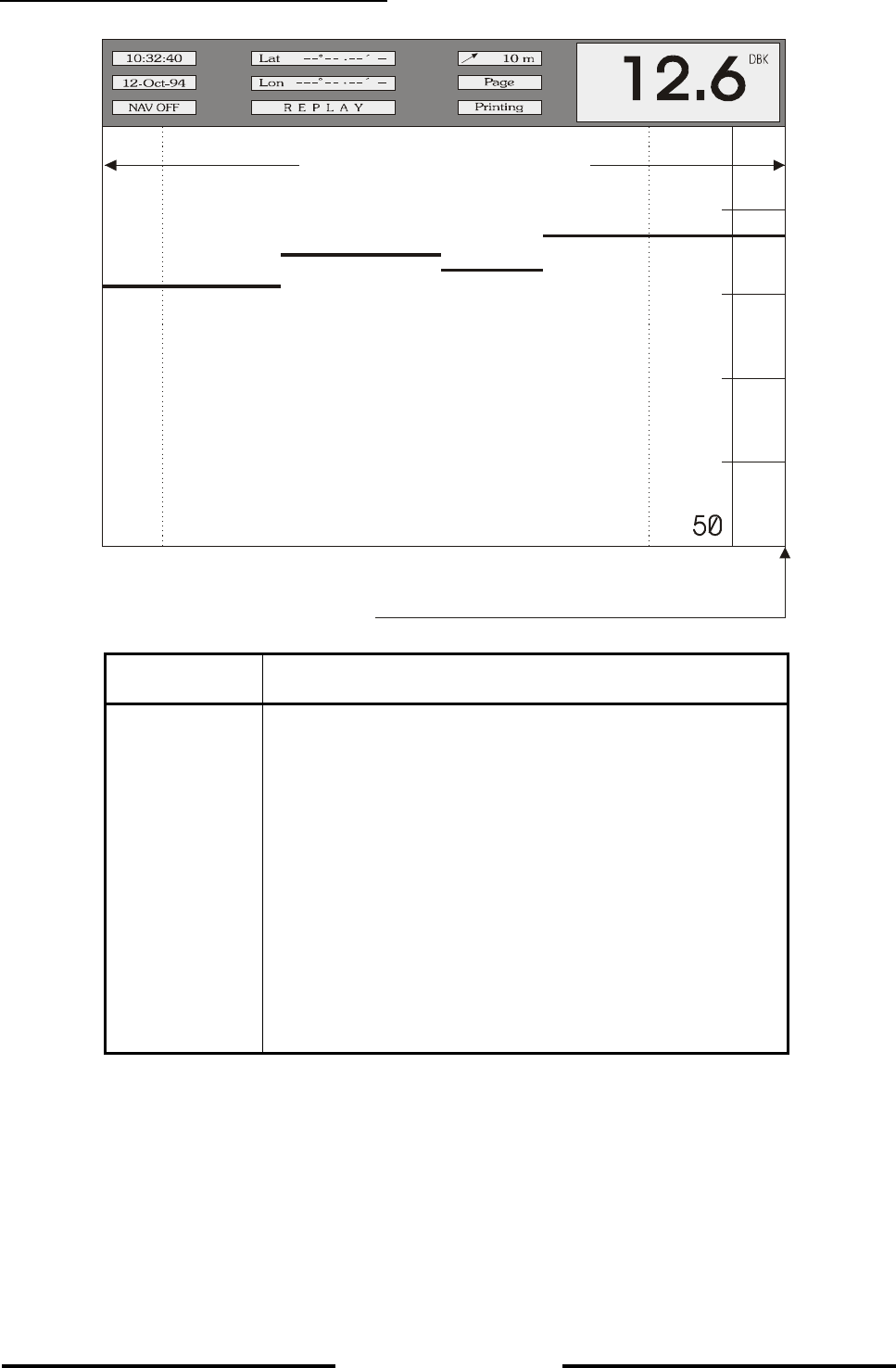
Printing data from the memory
In order to make a print-out of all or part of the data stored in the memory, so called "limit markers"
must be set. Only data within these limit markers will be printed out. To set these limit markers and
print the data within them, proceed as follows:
• Scroll the display area until one limit is reached (the time can be seen in the "time
window").
• Press the MARKER key (the time of the right hand side of the display appears in a
window below the depth alarm window)
• Scroll the display area until the other limit is reached (the time can be seen in the
"time window").
• Press the PRINT key, the time in the window below the depth alarm window will be
replaced by the word "Wait", followed after a short time by the word "Printing".
During printing, the user may scroll further within the memory. The print-out can be stopped at any
point by pressing the PRINT key for a second time.
Fault conditions
When the PRINT key is pressed, a fault condition may exist. If so, one of the 3 fault conditions
shown below will be indicated in the window beneath the depth alarm window:
• PERIOD? : This indicates that the user has set the both limit markers to the
same time. The limit markers must be set to different times.
• PAPER OUT : The printer has run out of paper
• ERROR : The printer is not connected, not switched ON, or otherwise
defective
Making a hard copy of the screen
In order to make a hard copy of data displayed on the screen, scroll to the desired position and
press the PRINT key. A window will appear containing the word "Hardcopy". The print-out will be
an exact reproduction of the screen at the time the PRINT key was pressed.
NOTE: With the exception of the PRINT and ESCAPE push-buttons, all other controls
are "dead" during the time it takes to print out a hard copy of the screen. The
PRINT push-button will stop the printing process and the ESCAPE push-
button will exit the LOG-DATA feature and return the system to Echo-
sounding operation.

Page 4-26
L-3 ELAC Nautik
4.5.4 THE SYSTEM SET-UP MENU
WARNING: With the exception of the time, date and contrast, no other parameters must
be altered unless modifications are made to the system, e.g. altering the
installation depth of the transducer, replacing the transducer for one of a
different frequency. Alteration of such parameters must only be made by an
experienced service technician.
PARAMETER ALTERATIONS MADE BY NON-QUALIFIED PERSONS MAY LEAD TO
INCORRECT DEPTH READINGS WHICH IN TURN CAN LEAD TO MATERIAL DAMAGE AND
TO THE LOSS OF LIFE AND LIMB
To call up the SYSTEM SET-UP MENU, press the ENTER key four times. The MENU as shown
below will appear.
The SYSTEM SET-UP MENU is used to set the Time and Date and to gain access to the
SERVICE and INTERFACE SUB MENUS to allow the service technician to alter installation and
interface parameters (see above warning).
Changing the Date and Time
To change the system DATE, call up the SYSTEM SET-UP MENU and press the following keys:
• CURSOR W (1x, to mark the word Date)
• ENTER (1x, to mark the day setting)
• CURSOR W or V (to alter the day setting)
• ENTER (1x, to confirm selection and jump to the month setting)
• CURSOR W or V (to alter the month setting)
Date 29.06.94
Time 12:34
Color up
Color down
Version
SYSTEM-SETUP
Service >>
Version number and date

Page 4-27
L-3 ELAC Nautik
• ENTER (1x, to confirm selection and jump to the year setting)
• CURSOR W or V (to alter the year setting)
• ENTER (1x, to confirm selection)
• ESCAPE (2x, to leave the MENU)
To change the system TIME, call up the SYSTEM SET-UP MENU and press the following keys:
• CURSOR W (2x, to mark the word Time)
• ENTER (1x, to mark the hour setting)
• CURSOR W or V (to alter the hour setting)
• ENTER (to confirm selection and jump to the minutes setting)
• CURSOR W or V (to alter the minutes setting)
• ENTER (1x, to confirm selection)
• ESCAPE (2x, to leave the MENU)

Page 4-28
L-3 ELAC Nautik
COLOR BAR MENU allows user settings according to ambient conditions. Several combinations
of echo indication and the overlay of general information are possible
according the following table.
Example: CC B>R means
CC: Colored overlay, Colored echotrace
B>R: Blue are week echoes, Red are strong echoes
CODE
LETTERS
1+2
OVERLAY LETTERS
3+4
ECHOLEVEL COLORS
Text Background High Low
CC Black Colored B>W White Black 8 blue to white on black
GC Grey Dark grey B>W White Black 8 blue to white on black
GG Grey Dark grey B>W White Black 16 grey level on black
GG Grey Dark grey W>B Black White 16 grey level on white
CC Black Colored B>R Red Black 16 blue to red on black
GC2 Grey Dark grey B>R Red Black 16 blue to red on black
CC Black Colored B>W White Black 8 blue to white on black
GC Black Dark grey B>W White Black 8 blue to white on black
GG Black Dark grey B>W White Black 16 grey level on black
GG Black Dark grey W>B Black White 16 grey level on white
CC Black Colored B>R red black 16 blue to red on black
GC Grey Dark grey B>R Red Black 16 blue to red on black
Installation settings are made within the SERVICE and INTERFACE SUB-MENUS which are
described in Chapter 5.

Page 5-1
L-3 ELAC Nautik
5 INSTALLATION, CARE AND MAINTENANCE
5.1 INSTALLATION
The display and control unit can be panel, bulkhead, deckhead or console mounted. The system is
delivered with mounting brackets as specified by the user. Install the display and control unit in
accordance with the relevant section of the Installation Drawing Number EZ 52 590 8001 to 8010
which can be found in chapter 6 "DRAWINGS" of this handbook.
The mounting place should assure, that no direct sun light influences the visibility of the display
and for clear display readings a viewing angle of ± 50° perpendicular to the display is
recommended.
The echosounder performance is limited by the acoustic in-water characteristics. These are mainly
influenced by the transducer mounting position, the operating frequency and the efficiency of
electrical-acoustical conversion.
The transducer position must be selected in a way that the radiating surface is mounted in an area
virtually free of turbulence and air bubbles. The sound waves are reflected by any layers of air
bubbles or turbulence that strong, that the sound can not pass the layers and thus echosounding is
prevented.
Because of this fact the transducers should be mounted within the ship's bow area. In case of an
existing bow thruster, the transducer must be mounted ahead or below the thruster outlet. If
mounted behind the bow thruster, the performance of the echosounder will be degraded by
turbulence and air bubbles. Even a total echosounding break down is possible.
During bow thruster operation echosounding is not possible because a wide area around the
thruster´s outlet is saturated with turbulence and air bubbles.
On ships equipped with a bulb bow the transducer must be mounted ahead as far as possible,
because the bulb generates a layer of air bubbles that heavily reduces the transducer /
echosounder performance.
A transducer mounted in the vicinity of the ship's stern can be operated only while drifting, at the
pier or at very low speed. The reason is that the stern area is generally disturbed by turbulence
and air bubbles, dependent on ship's speed. Additionally vibrations and engine noise may be a
source of disturbances. The sound signal cannot penetrate this layer, the bottom echo fades away
and the digital display shows the zero echo ( 1 - 1.5 m) or "?". For this reason only the front
transducer must be used while sailing.

Page 5-2
L-3 ELAC Nautik
Once the transducer has been installed, the system must be set up to take certain factors into
consideration. These are:
• Never paint the radiating surface of the transducer.
• Transducer installation depth beneath the surface.
• Transducer installation height relative to the lowest part of the ship's keel.
• Blocking depth, a setting to prevent false digital depth readings caused by resonance of
non-ELAC transducers. This setting need not be altered from ZERO if using ELAC
transducers.
• Frequency of the transducer.
• Installation position of the transducer, e.g. BOW, AFT, Pt., Stb, (if 2 transducers are
installed).
When a transducer is installed, i.e. before the ship is launched, measure the height difference
between the radiating surface of the transducer and the lowest part of the keel and the distance
between the waterline and the radiating surface of the transducer. These measurements are
needed to compensate the differences when the system is initially set up. The transducer
frequency can be found in the shipping documents.
Connect the system up in accordance with the connection diagram which can be found in chap. 6.
When cabling the system, take especial care that all signal lines are screened properly. The cable
from the transducer to the connection box must be laid in an iron tube. From the connection box to
the echo sounder there are three choices for a proper cable laying:
- the transducer cable is laid within an iron tube
- a double-screened cable is used as transducer cable, the inner screen is one-side
connected to the echosounder's ground, the outer screen is one-side connected to the
ship's ground.( see Figure 5- 1)
- the transducer cable is laid apart at least 500 mm from all other cables.
By no means a single screened cable must be laid together with any other cable.

Page 5-3
L-3 ELAC Nautik
5.1.1 DISTORTION LEVEL TEST
After routing and connecting the transducer cable a distortion level test has to be carried out, to
ensure the correct routing and screening of the transducer cables.
Test procedure:
1. Switch on the echosounder LAZ 5100
2. Select 500 m range
3. Select Display Gain 10 (max.)
4. Select Display Mode 1/2 for Dual Channel Unit
5. Select Item Gain, man. in the Parameter Menu
6. Select Gain 15 (max.)
7. Check the recording on the LCD – Screen. Below the transmitting pulse and echo signals no or
only light distortion shall appear on the screen.
8. If strong distortion appear, check and correct transducer cable routing and screening according
to the Installation Instruction.
9. Repeat test procedure until the display is free of distortion.
10. Return to normal mode
Connect up peripheral equipment, i.e. external PC, printer, remote display unit etc. in accordance
with the above mentioned connection diagram and referring to Figure 3-3 in chapter 3.5.
Page 5-4
L-3 ELAC Nautik
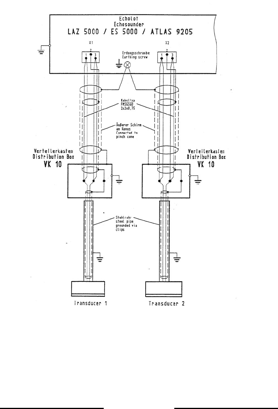
Figure 5-1 Instruction for transducer- cable connection
Kabelklemmen nur zur
Befestigung der Wandlerkabel
Cable Clamps only for fixing of
Transducer Cables
Kabellänge zwischen VK 10 und
Wandler max. 30 m
Cable Length between VK 10 and
Transducer max. 30 m

Page 5-5
L-3 ELAC Nautik
Transducer
Type Frequency Manufacturer
Electrical
Power
Maximum
Cable Length
Maximum
Waterdepth
LSE 131 30 kHz Elac Nautik 1000 Watt 600 m
(2x1,5mm2)2200 m
LSE 132 30 kHz Elac Nautik 450 Watt 600 m
(2x1,5mm2)1200 m
LSE 297 50 kHz Elac Nautik 250 Watt 400 m
(2x1,5mm2)600 m
LSE 133 50 kHz Elac Nautik 450 Watt 600 m
(2x1,5mm2)1100 m
SW 6016 100 kHz STN Atlas 200 Watt
150 m
(2x1,5mm2)
250 m
(2x2,5mm2)
300 – 350 m
LSE 148 100 kHz Elac Nautik 450 Watt
200 m
(2x1,5mm2)
300 m
(2x2,5mm2)
350 – 400 m
LSE 313 200 kHz Elac Nautik 250 Watt
150 m
(2x1,5mm2)
250 m
(2x2,5mm2)
250 – 300 m
LSE 135 200 kHz Elac Nautik 250 Watt
150 m
(2x1,5mm2)
250 m
(2x2,5mm2)
250 – 300 m
Table 5-1 Transducer type

Page 5-6
L-3 ELAC Nautik
5.1.2 INITIAL SYSTEM SET-UP
After installation of the LAZ 5100 please follow this procedure for setting into operation the first
time.
No. Item Result
1. Installation check
1.1 Main su
pp
l
y
(
X3
)
1.2 Transducer
(
X1
,
X2
)
– cable screenin
g,
cable la
y
in
g
1.3 Printer
(
X7
)
– max. cable len
g
th 5 m
1.4 NMEA – Out
p
ut
(
X8
)
– RS 422
1.5 NMEA – In
p
ut
(
X4
)
– RS 422
1.6 Start / Sto
p
– Out
p
ut
(
X8
)
1.7 NMEA – Out
p
ut
(
X6
)
– RS 422
2. Settin
g
into o
p
eration
2.1 Disconnect Printer
,
NMEA - In
p
ut and Out
p
ut
2.2 Onl
y
Main Su
pp
l
y
and Transducer connected
2.3 Switch
„
ON“ the unit
2.4 Check and do basicall
y
settin
g
s
- fre
q
uenc
y
- sound velocit
y
(
1.500 m/s
)
- blockin
g
de
p
th
(
2 - 2.9 m
)
- draft
,
trim
- NMEA - Interface
(
4.800 baud
,
8N1
)
- date and time
2.5 Check the function of the unit
- de
p
th recordin
g
- LC - Dis
p
la
y
2.6 Check distortion level
- select 500 m ran
g
e
- select item Manual Gain
- select
g
ain Vmax
(
15
)
- no or li
g
ht distortion shall a
pp
ear on the LCD – screen
- reduce
g
ain
,
until the screen is free of distortion
- notice
g
ain level
- return to normal mode
2.7 Connect NMEA - Out
p
ut
(
if re
q
uested
)
- check data at receivin
g
unit
2.8 Connect NMEA - In
p
ut
(
if re
q
uested
)
- check data on LC- Dis
p
la
y
2.9 Connect Printer
(
if available
)
- check recordin
g
on
p
rinte
r
2.10 Connect Start/Sto
p
- Out
p
ut
(
i.e. DAZ 13
)
(
if re
q
uested
)
3. Sea Trial
3.1 Check the
p
erformance of the transduce
r
- distortion
(
airbubbles
,
turbulence
)
under the
- recordin
g
free of electrical noise?
- de
p
th indication
,
analo
g
ue and di
g
ital

Page 5-7
L-3 ELAC Nautik
Once the system has been correctly installed, the initial set-up can be carried out. Call up the
SYSTEM SET-UP MENU by pressing the ENTER key four (4) times. When the SYSTEM SET-UP
MENU appears on the display area, press the CURSOR W key three (3) times so that the word
Service is highlighted as shown below.
Press the ENTER key and the WARNING shown below will appear.
Changing parameters
in the following
menus should only
be done by qualified
persons
Continue ? NO NO/YES, select YES for SERVICE menu
WARNING!
WARNING: Only qualified service technicians are allowed to alter these system settings. If
you are not authorised to alter these settings, DO NOT continue. Press either
the ENTER or ESCAPE key to return to the SYSTEM SET-UP menu.
UNAUTHORISED ALTERATION OF THESE SETTINGS CAN ENDANGER THE SAFETY OF
THE SHIP AND LEAD TO LOSS OF LIFE AND LIMB.
If not authorised to make alterations, press the ESCAPE or ENTER key to return to the
SYSTEM SET-UP menu.
Date 11.02.03
Time 12:34
Color up
Color down
Version
SYSTEM-SETUP
Service >>
Version number and date
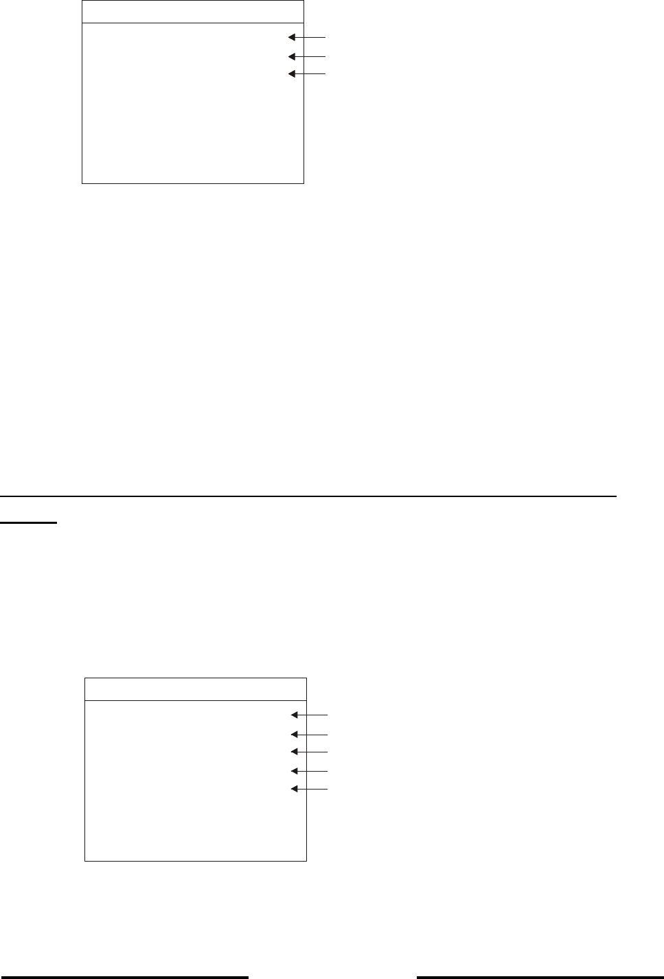
Page 5-8
L-3 ELAC Nautik
Access to the SERVICE MENU is gained by pressing any CURSOR key. The word NO will change
to YES. Press the ENTER key and the SERVICE MENU, shown below, will appear.
The SERVICE MENU allows the service technician to access the following sub-MENUS:
• Channel 1 - allows selection of Draft, Trim, Blocking Depth, Frequency and
Location for the Channel 1 transducer.
• Channel 2 - allows selection of Draft, Trim, Blocking Depth, Frequency and
Location for the Channel 2 transducer, if fitted. If no 2nd Channel is
fitted, this MENU is not available
• Interfaces - allows selection of parameters for data transfer.
• Display 15 min altering the selection of the recording display time.
In order to set or alter the parameters for Channel 1, call up the CHANNEL 1 MENU, as
follows:
• Call up the SERVICE MENU as previously described
• CURSOR W (1x, to mark Channel 1)
• ENTER (1x, to call up the Channel 1 parameters MENU as seen below)
Draft 0.0 (0.0..29.9 m)
Trim 0.0 (0.0...4.9 m)
Blocking Depth 0.0 (0.0...2.9 m)
CHANNEL 1
Frequency 50 (28, 33, 38, 50, 100, 200, 210 kHz)
Location BOW (BOW, AFT, Stb., Pt.)
Channel 1 >> To call up Channel 1 parameter MENU
Channel 2 >> To call up Channel 2 parameter MENU
Interfaces >> To call up interface parameter MENU
SERVICE
Display 15 min ON ON - OFF
Channel 1 >> To call up Channel 1 parameter MENU
Channel 2 >> To call up Channel 2 parameter MENU
Interfaces >> To call up interface parameter MENU
SERVICE
Display 15 min ON ON - OFF
Channel 1 >> To call up Channel 1 parameter MENU
Channel 2 >> To call up Channel 2 parameter MENU
Interfaces >> To call up interface parameter MENU
SERVICE
Display 15 min ON ON - OFF
Power adjust

Page 5-9
L-3 ELAC Nautik
The CHANNEL 1 MENU allows the service technician to set the following parameters:
• Draft the transducer installation depth is entered here, i.e. the depth
of the transducer below the waterline, e.g. 5.6 m. This
compensation allows accurate surface to sea bed
measurements..
• Trim the distance between the transducer and the lowest part of the
keel is entered here, e.g. 0.3 m. This compensation allows
accurate keel to sea bed measurements.
• Blocking depth this setting is to prevent false digital depth readings caused by
the effects of resonance of non-ELAC transducers. If the water
depth is less than the depth set here, the digital display will show
a „?“ but the analogue depth reading will be displayed correctly.
• Frequency the transducers working frequency is entered here, e.g. 50 kHz.
• Location the position where the transducer is installed is entered here,
e.g. BOW. This parameter can not be altered for single
channel systems.
To alter the Draft setting, press the following keys:
• Call up the CHANNEL 1 SUB MENU as described previously
• CURSOR W (1x, to mark the word Draft)
• ENTER (1x, to mark the 1st digit)
• CURSOR W or V (to alter the metre (1st digit) setting)
• ENTER (1x, to confirm selection and jump to 2nd digit)
• CURSOR W or V (to alter the 1/10th of a metre (2nd digit) setting)
• ENTER (1x, to confirm selection)
• ESCAPE (2x, to leave the MENU)
To alter the Trim setting, press the following keys:
• Call up the CHANNEL 1 SUB MENU as described previously
• CURSOR W (2x, to mark the word Trim)
• ENTER (1x, to mark the 1st digit)
• CURSOR W or V (to alter the metre (1st digit) setting)
• ENTER (1x, to confirm selection and jump to 2nd digit)
• CURSOR W or V (to alter the 1/10th of a metre (2nd digit) setting)
• ENTER (1x, to confirm selection)
• ESCAPE (2x, to leave the MENU)
To alter the Blocking Depth setting, press the following keys:

Page 5-10
L-3 ELAC Nautik
• Call up the CHANNEL 1 SUB MENU as described previously
• CURSOR W (3x, to mark the word Blocking Depth)
• ENTER (1x, to mark the 1st digit)
• CURSOR W or V (to alter the metre (1st digit) setting)
• ENTER (1x, to confirm selection and jump to 2nd digit)
• CURSOR W or V (to alter the 1/10th of a metre (2nd digit) setting)
• ENTER (1x, to confirm selection)
• ESCAPE (2x, to leave the MENU)
To alter the Frequency setting, press the following keys:
• Call up the CHANNEL 1 SUB MENU as described previously
• CURSOR W (3x, to mark the word Frequency )
• ENTER (1x, to mark the frequency selected e.g. 200)
• CURSOR W or V (to alter the setting)
• ENTER (1x, to confirm selection)
• ESCAPE (2x, to leave the MENU)
IMPORTANT NOTE: The new setting can only be activated by re-starting the system (i.e.
switch the system OFF and then ON again).
To alter the Location setting, press the following keys:
• Call up the CHANNEL 1 SUB MENU as described previously
• CURSOR W (5x, to mark the word Location )
• ENTER (1x, to mark the location selected e.g. BOW)
• CURSOR W or V (to alter the setting)
• ENTER (1x, to confirm selection)
• ESCAPE (2x, to leave the MENU)
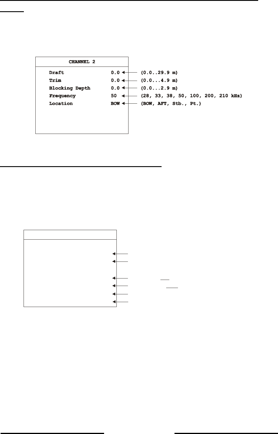
Page 5-11
L-3 ELAC Nautik
In order to set or alter the parameters for Channel 2, call up the CHANNEL 2 MENU, as
follows:
• Call up the SERVICE MENU as previously described
• CURSOR W(2x, to mark Channel 2)
• ENTER (1x, to call up the Channel 1 parameters MENU as seen below)
Proceed from here in exactly the same way as described for Channel 1 settings.
To call up the INTERFACE MENU. proceed as follows:
• Call up the SERVICE MENU as described previously
• CURSOR W (3x, to mark the word Interfaces)
• ENTER (1x, to call up the INTERFACES SUB-MENU)
The INTERFACE MENU shown below will appear.
External PC
Mode 8N1 (7E1, 7E2, 8N1, 8E1, 8N2, 8E2)
Baud 19200 (1200, 2400, 4800, 9600, 19200, 38400 Baud)
NMEA/DAZ 25
Mode 8N1 (7E1, 7E2, , 8E1, 8N2, 8E2)8N1
Baud 4800 (1200, 2400, , 9600, 19200, 38400 Baud)4800
Rep. rate SLOW (SLOW, FAST)
INTERFACES
Protocol DPT/DBT (DPT/DBT, ELAC)
This menu allows the service technician to assign the interfaces to fit to other peripheral
equipment, e.g. a personal computer or digital slave indicators.

Page 5-12
L-3 ELAC Nautik
To alter the External PC Mode, press the following keys:
• Call up the INTERFACES SUB-MENU as described previously
• CURSOR W (1x, to mark the word Mode)
• ENTER (1x, to mark the selected mode)
• CURSOR W or V (to alter the mode)
• ENTER (1x, to confirm selection)
• ESCAPE (2x, to leave the MENU)
To alter the External PC Baud rate, press the following keys:
• Call up the INTERFACES SUB-MENU as described previously
• CURSOR W (2x, to mark the word Baud)
• ENTER (1x, to mark the selected Baud rate)
• CURSOR W or V (to alter the Baud rate)
• ENTER (1x, to confirm selection)
• ESCAPE (2x, to leave the MENU)
To alter the NMEA/DAZ 25 Mode, press the following keys:
WARNING: The NMEA/DAZ 25 interface Mode and Baud rate are laid down by the National
Marine Electronics Association. If these are altered, the interface will no
longer be to this NMEA standard.
• Call up the INTERFACES SUB-MENU as described previously
• CURSOR W (3x, to mark the word Mode)
• ENTER (1x, to mark the selected mode)
• CURSOR W or V (1x, to alter the mode)
• ENTER (1x, to confirm selection)
• ESCAPE (2x, to leave the MENU)
To alter the NMEA/DAZ 25 Baud rate, press the following keys:
• Call up the INTERFACES SUB-MENU as described previously
• CURSOR W (5x, to mark the word Baud)
• ENTER (1x, to mark the selected Baud rate)
• CURSOR W or V (to alter the Baud rate)
• ENTER (1x, to confirm selection)
• ESCAPE (2x, to leave the MENU)

Page 5-13
L-3 ELAC Nautik
To alter the Protocol, press the following keys:
• Call up the INTERFACES SUB-MENU as described previously
• CURSOR W (6x, to mark the word Protocol)
• ENTER (1x, to mark the selected Protocol)
• CURSOR W or V (to alter the Protocol)
• ENTER (1x, to confirm selection)
• ESCAPE (2x, to leave the MENU)
Note, that the Protocol ELAC is only applicable for dual channel units, see also chapter 3.5.1
Description of Interfaces.
To alter the recording display time on the LCD – Screen, press the following keys
Call up the Display 15 min Sub Menu as described previously
- Enter (1x), to mark “ON” or “OFF”
- Cursor to alter the setting
- Enter (1x), to confirm the selection
- Escape(2x), to leave the Menu
Once the initial system settings have been made they need only be altered if for example a 2nd
transducer is added or the original transducer is replaced for one of a different frequency.
If a 2nd transducer is added at a later date, parameters must be entered in the channel 2 sub-
menu. The parameters for channel 1 must not be altered. ( See installation instruction
UN 52 590 4001 for the integration of the second channel).
If the original transducer is replaced and the replacement is fitted at a different location, the
parameters must be altered accordingly.
5.1.3 POWER ADJUST
This adjust feature allows the authorised service person to alter the transmit power according to
cable length on bord.
5.2 CARE AND MAINTENANCE
The LAZ 5100 Navigation Echo Sounder is largely maintenance free. The transducer(s) should be
cleaned whenever an opportunity arises, e.g. when the ship is in dock. The Transducer(s) can be
cleaned using a plastic scraper or scrubbing brush, see note below.
NOTE: Never use metal scrapers or wire brushes to clean the transducer(s). Never
paint the radiating surface of the transducer(s).

Page 5-14
L-3 ELAC Nautik
The housing of the control and display unit can be cleaned using a non-abrasive household
cleaning agent. Use window/glass cleaning fluid to clean the display area screen. Do not apply
unnecessary pressure to the screen area when cleaning.
If the system cables are exposed, i.e. are not run in ducts or tubes, check them at monthly
intervals for insulation damage.
If the system is defective and requires repair, onboard service is normally not possible because of
the high density electronics. Onboard service is done by exchanging PCB´s ( Printed Circuit
Boards), a list of spare parts available can be seen overleaf. Order spares from the address below
stating part(s) required and ident. number(s).
L-3 Communications ELAC Nautik GmbH
Neufeldtstrasse
24118 Kiel
Germany

Page 5-15
L-3 ELAC Nautik
5.3 SPARE PARTS LIST
Spare Part Ident. No.
Power supply unit.........................................................................................
Printed circuit board A3................................................................................
Fuses (line) F1, F2, T2A...............................................................................
Main board PSE 33......................................................................................
Frontpanel complete....................................................................................
.......06 990 0274
.......52 603 181801
.......06 710 1200
.......57 319 8001
.......52 603 1002

Page 6-1
L-3 ELAC Nautik
6 DRAWINGS
Dimensional drawing : MB 52 603 8001
: MB 54 555 1101
: MB 54 555 8002 to 8004
: MB 54 568 1101
: MB 54 568 8001
Installation drawing : EZ 52 603 8001
: EZ 54 555 8002 to 8004
: EA 54 555 8002
: EZ 54 568 8001
: EA 54 568 8001
Circuit diagram: : SP 52 590 8001
Connection Diagram : VE 44 390 8001
Cable Joining List : KA 44 390 8001
