L3 Fuzing and Ordnance Systems 25TWD3000 RANGE-R Handheld Through Wall Radar User Manual FCC Part 15
L-3 Communications CyTerra Corporation RANGE-R Handheld Through Wall Radar FCC Part 15
Manual

5015 B.U. Bowman Drive Buford, GA 30518 USA Voice: 770-831-8048 Fax: 770-831-8598
Certification Exhibit
FCC ID: YKD-25TWD3000
FCC Rule Part: CFR 47 Part 90, DA 09-2482
ACS Report Number: 10-0003.W03.11.A
Applicant: L-3 Communications CyTerra
Model: RANGE-R
Manual
MAN-0001 Rev C
OPERATOR’S MANUAL
RANGE-R™
This RANGE-R Handheld Through Wall Radar is controlled under the U.S. International Traffic
in Arms Regulations (ITAR) and may not be exported without proper authorization by the U.S.
Department of State.

CAUTION
Inserting the batteries into the unit in the wrong orientation may
cause the batteries to overheat or explode. Care should be taken to
insert the batteries correctly. Failure to follow the appropriate
procedure may cause damage to the equipment.
CAUTION
The battery compartment is not internally watertight, thus care
should be exercised when the battery door is open to ensure liquids
do not enter the compartment where it is possible for them to leak
into the internal electronics. Failure to follow this caution may cause
damage to the equipment.
CAUTION
It is essential that the operator remain as still as possible when
performing scanning operations in order to achieve the best
overall detection performance. Failure to follow this caution
could result in false alarms and degraded detection performance.
SAFETY SUMMARY
WARNINGS
When the degraded breather detection indicator is illuminated on the
display, only large body movements will be detected. Small body
movements such as respirations may not be detected. This should be
taken into account when making mission oriented operational
decisions. Failure to follow this warning could result in death or injury.
To avoid possible wall blockage scenarios, an operator must observe
the building material to avoid scanning through metal or absorptive
material. The building material should be taken into account when
making mission oriented operational decisions. Failure to follow this
warning could result in death or injury.
The RANGE-R™ system’s best detection performance occurs directly
in front of the unit and extends out ±80 degrees in a conical pattern.
Outside of this area the detection performance rapidly degrades. This
should be taken into account when making mission oriented
operational decisions. When possible, the operator should perform
scans at different locations along the wall surface to maximize
coverage of the target area. Failure to follow this warning could result
in death or injury.
There is a region above the display marked “Sensor Area – Do Not
Block.” This region should not be covered by the operator’s hand. This
region houses an antenna used to sense and reject nuisance
detections that may arise from operator-side motion. Failure to do so
could result in false alarms and degraded detection performance.
ii

SAFETY SUMMARY
WARNINGS
Inserting the batteries into the unit in the wrong orientation may cause
the batteries to overheat or explode. Care should be taken to insert the
batteries correctly. Failure to follow the appropriate procedure may
cause damage to the equipment.
The battery compartment is not internally watertight, thus care should
be exercised when the battery door is open to ensure liquids do not
enter the compartment where it is possible for them to leak into the
internal electronics. Failure to follow this caution may cause damage
to the equipment.
If the RANGE-R™ system is placed in the case with a side facing up,
the scan buttons may be pressed when the case is closed, causing the
unit to transmit. This will drain the batteries and may cause the system
to overheat. This may possibly damage the device.
This RANGE-R Handheld Through Wall Radar is controlled under the
U.S. International Traffic in Arms Regulations (ITAR) and may not be
exported without proper authorization by the U.S. Department of State.
iii
FCC COMPLIANCE
WARNING
Do not open the unit. There are no user serviceable parts contained
within the unit, and opening or tampering with it will void the FCC
certification and the manufacturer’s warranty.
This device is approved for use by the FCC under FCC Order DA 09-2482, FCC ID
YKD-25TWD3000.
Warning: Changes or modifications to this device not expressly approved by L-3
CyTerra could void the user’s authority to operate the equipment.
“This equipment complies with FCC radiation exposure limits set forth for an
uncontrolled environment. This equipment should be installed and operated with
minimum distance 20cm between the radiator and your body. This transmitter must
not be co-located or operating in conjunction with any other antenna or transmitter.”
“NOTE: This equipment has been tested and found to comply with the limits for a
Class B digital device, pursuant to Part 15 of the FCC Rules. These limits are
designed to provide reasonable protection against harmful interference in a
residential installation. This equipment generates, uses, and can radiate radio
frequency energy and, if not installed and used in accordance with the instructions,
may cause harmful interference to radio communications. However, there is no
guarantee that interference will not occur in a particular installation. If this equipment
does cause harmful interference to radio or television reception, which can be
determined by turning the equipment off and on, the user is encouraged to try to
correct the interference by one or more of the following measures:”
• Reorient or relocate the receiving antenna.
• Increase the separation between the equipment and receiver.
• Connect the equipment into an outlet on a circuit different from that to which the
receiver is connected.
• Consult the dealer or an experienced radio/TV technician for help.
For any questions related to FCC compliance contact L-3 CyTerra Technical Support.
iv
TABLE OF CONTENTS
Page
SAFETY SUMMARY.................................................................................................................. ii
FCC COMPLIANCE ..................................................................................................................iv
TABLE OF CONTENTS ............................................................................................................. v
CHAPTER 1 INTRODUCTION...............................................................................................1
SECTION I GENERAL INFORMATION...............................................................................1
1.1 SCOPE..............................................................................................................1
1.2 LIST OF ACRONYMS/ABBREVIATIONS .........................................................1
SECTION II EQUIPMENT DESCRIPTION AND DATA ........................................................3
1.3 EQUIPMENT CHARACTERISITICS, CAPABILITIES, AND FEATURES..........3
1.4 LOCATION AND DESCRIPTION OF MAJOR COMPONENTS........................3
1.5 EQUIPMENT DATA ..........................................................................................4
SECTION III THEORY OF OPERATION ...............................................................................5
1.6 TECHNICAL PRINCIPLES OF OPERATION....................................................5
CHAPTER 2 OPERATOR INSTRUCTIONS..........................................................................6
SECTION I DESCRIPTION AND USE OF OPERATOR CONTROLS AND INDICATORS .6
2.1 OPERATOR CONTROLS AND INDICATORS..................................................6
SECTION II SYSTEM OPERATION .....................................................................................7
2.2 PREPARATION FOR USE................................................................................7
2.3 POWERING THE SYSTEM ON........................................................................7
2.4 BRIGHTNESS ADJUSTMENT..........................................................................8
2.5 SCAN MODE ....................................................................................................8
2.6 FACTORS AFFECTING DETECTION ............................................................10
2.6.1 INTERFERENCE ............................................................................................10
v
2.6.2 Operator and Rearward Motion.......................................................................11
2.6.3 Wall Blockage .................................................................................................12
2.6.4 Water and Moisture.........................................................................................13
2.6.5 Blind Spots......................................................................................................13
2.6.6 False Range Indication....................................................................................13
2.6.7 Hollow Building Materials ................................................................................14
2.7 FAULT AND STATUS MODES .......................................................................14
2.7.1 Battery Status.................................................................................................. 14
2.7.2 Built-In-Test Failures ....................................................................................... 15
CHAPTER 3 OPERATOR MAINTENANCE INSTRUCTIONS
SECTION I INSPECTIONS AND STORAGE.....................................................................17
3.1 INSPECTIONS................................................................................................17
3.1.1 Preoperational Inspections..............................................................................17
3.1.2 Post Operational Inspections ..........................................................................17
3.2 STORAGE.......................................................................................................18
SECTION II SERVICE AND SUPPORT.............................................................................. 19
3.3 SERVICE / WARRANTY.................................................................................19
3.4 TECHNICAL SUPPORT..................................................................................19
vi
LIST OF ILLUSTRATIONS
Figure Number Page
1-1 RANGE-R™ Components ...............................................................................................3
2-1 RANGE-R™ – Controls and Indicators............................................................................6
2-2 Standby Mode Display.....................................................................................................8
2-3 Adjust Brightness Mode Display......................................................................................8
2-4 Scan Mode Displays......................................................................................................10
2-5 Diminished Breather Detection Display .........................................................................12
2-6 Blocked Detection Display.............................................................................................13
2-7 Blind Spots ....................................................................................................................13
2-8 Battery Status Displays ................................................................................................. 15
2-9 Fault Displays................................................................................................................16
vii
viii
LIST OF TABLES
Table Number Page
2-1 RANGE-R™ Control and Indicator Functions..................................................................6

CHAPTER 1
INTRODUCTION
SECTION I - GENERAL INFORMATION
1.1 SCOPE.
This manual provides instructions for operating and service information for the
RANGE-R™ (Electro-Magnetic Motion Detection and Ranging) system. It includes a
description of the hardware, its controls and indicators, and operating procedures.
To obtain the best performance and margin of safety, it is imperative that the operator
familiarize themselves with the contents of this manual and train with the system on a
regular basis in order to fully understand the system’s capabilities and limitations.
1.2 LIST OF ACRONYMS/ABBREVIATIONS.
Acronym/Abbreviation Definition
Br Breather
BIT Built-in-Test
C Celsius
CBIT Continuous Built-in-Test
cm centimeter
DSP Digital Signal Processor
F Fahrenheit
ft Foot
in Inch
kg Kilogram
lb Pound
LED Light Emitting Diode
MOV Mover
PLL Phase Locked Loop
PMCS Preventative Maintenance Checks and Services
1

1.2 LIST OF ACRONYMS/ABBREVIATIONS (Continued).
Acronym/Abbreviation Definition
RF Radio Frequency
RMA Return Material Authorization
sec Second
SFCW Stepped Frequency Continuous Wave
Tx Transmit
VDC Volts Direct Current
2
SECTION II - EQUIPMENT DESCRIPTION AND DATA
1.3 EQUIPMENT CHARACTERISTICS, CAPABILITIES, and FEATURES.
The RANGE-R™ system is a highly sensitive, portable, handheld, battery operated
system. It is designed to detect moving and near stationary personnel through walls
constructed of common building materials. Anticipated uses of the RANGE-R™
system include room clearance operations and victim location by search and rescue
personnel engaged in disaster recovery efforts.
The system is comprised of a stepped-frequency continuous wave (SFCW) radar
transceiver, digital signal processor (DSP), display and power supply electronics
enclosed in a rugged, water-resistant, light-weight plastic housing. The operator
controls consist solely of the two momentary pushbutton switches located on the
sides of the unit. Target detection information and system status are shown on a
graphics display and two LED indicator lights on the front of the unit. Batteries used
to power the unit are accessed through a hinged door located on the bottom of the
unit that is secured by a thumb screw.
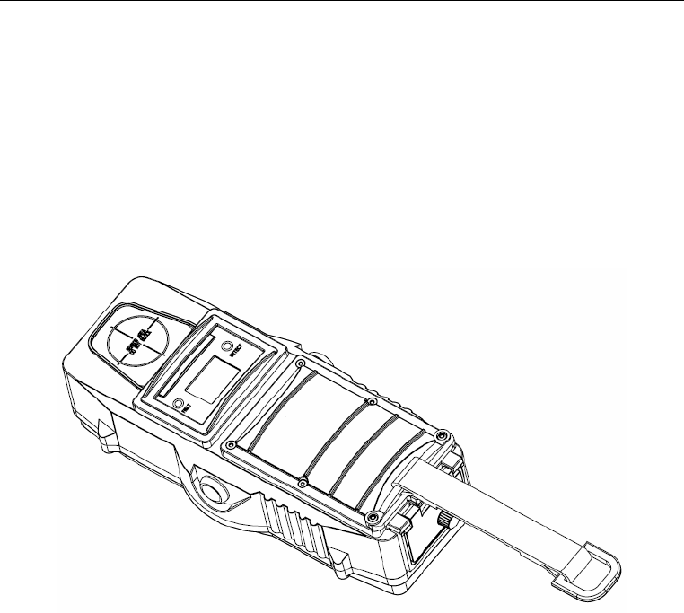
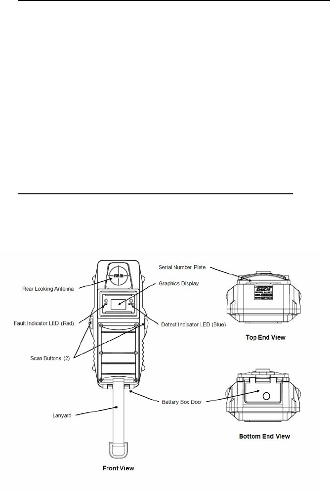
1.4 LOCATION AND DESCRIPTION OF MAJOR COMPONENTS
The major features of the RANGE-R™ system are: Rear Looking Antenna; Fault
LED, Detect LED, Graphics Display, Scan Button (2), Battery Door with Thumb
Screw, and Serial Number Plate.
Figure 1-1. RANGE-R™ Components
3

1.5 EQUIPMENT DATA
System Dimensions and Weight:
Length…………………………………………………………………....... 8.9 in (22.16 cm)
Width………………………………………………………………………. 4.0 in (10.16 cm)
Height……………………………………………………………………….. 2.7 in (6.86 cm)
Weight…………………………………………………………………….. 1.2 lbs (0.55 kg)
Battery:
Type……………………………………………..........4 each AA sized lithium batteries
Battery Life….……………………..…………………………………. >400 uses
Temperature
Operational Temperature Range………………………….0°F(-20°C) to 125°F (40°C)
4

SECTION III - THEORY OF OPERATION
1.6 TECHNICAL PRINCIPLES OF OPERATION.
The RANGE-R™ system uses safe levels of electro-magnetic radiation in the form of
radar signals to detect and measure the range to moving or near stationary personnel
through walls constructed of common building materials. The system is very sensitive
and can detect coarse body movements such as walking or fast head and arm
movements, as well as fine body motion such as chest movement caused by
respirations.
The RANGE-R™ system contains three (3) mounted antennas. Two of the antennas,
a transmit antenna and a receive antenna, face towards the target area. The third
antenna is a rear-looking antenna that faces the operator of the system and is used
in reducing the false alarm rate from movement of the user or behind the user.
When the RANGE-R™ system is in scan mode, radar waves are transmitted by the
transmit antenna through the wall and into the adjacent room/structure or area. The
radar waves travel until they strike an irregularity and are reflected back to the
receive antenna. The return signal is analyzed by a signal processing algorithm. If a
target is detected, the alert results are indicated on the graphics display and
illumination of the blue LED indicator light.
5
CHAPTER 2
OPERATOR INSTRUCTIONS
SECTION I - DESCRIPTION AND USE OF OPERATOR CONTROLS
AND INDICATORS
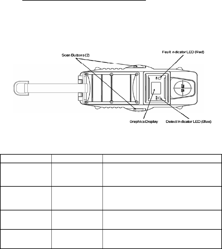
2.1 OPERATOR CONTROLS AND INDICATORS.
It is important to know the location and function of all controls associated with the
RANGE-R™ system prior to use to ensure proper and safe operation. The controls
used to operate the RANGE-R™ are located on each side and the indicators are
located on the front of the system (see Figure 2-1). The function of each item is
listed on Table 2-1.
Figure 2-1. RANGE-R™ – Controls and Indicators
ITEM COMPONENT FUNCTION
Scan Buttons (2) Momentary
Switch Mode Selection/ Scan
Graphics
Display LCD Screen Display detection information / BIT
functions
Fault Indicator Red LED BIT Fault
Detect Indicator Blue LED Positive Detection
Table 2-1. RANGE-R™ – Control and Indicator Functions
6

SECTION II - SYSTEM OPERATION
2.2 PREPARATION FOR USE.
WARNING
Inserting the batteries into the unit in the wrong orientation may
cause the batteries to overheat or explode. Care should be taken to
insert the batteries correctly. Failure to follow the appropriate
procedure may cause damage to the equipment.
WARNING
The battery compartment is not internally watertight, thus care
should be exercised when the battery door is open to ensure liquids
do not enter the compartment where it is possible for them to leak
into the internal electronics. Failure to follow this caution may cause
damage to the equipment.
Prior to operation, batteries need to be installed into the RANGE-R™ system. The
RANGE-R™ is designed to operate on four standard “AA” sized lithium batteries.
Alkaline AA batteries should not be used in the system. The following procedure is to
be used when installing the batteries into the RANGE-R™ system.
a. Open the battery door by unscrewing the thumbscrew located at the bottom
end of the unit.
b. Insert all batteries with the positive end first into the battery compartment.
c. Close the battery door and secure it by hand-tightening the thumbscrew.
2.3 POWERING THE SYSTEM ON.
Powering on the RANGE-R™ system will bring the unit into STANDBY Mode (see
Figure 2-2. In this mode, the radar is not active and target detection is not possible.
The following procedure is to be used to power on the RANGE-R™ system.
a. Depress both Scan buttons simultaneously and release.
b. As the unit powers on, first the Fault Indicator LED (Red) and then the Detect
Indicator LED (Blue) will momentarily turn on. This allows the operator to
know that the LEDs are functioning properly. The unit will show STANDBY
on the display as shown in Figure 2-2 when it is ready for operation.
c. If the unit is not used within one minute, the system will power down to
conserve battery life.
7
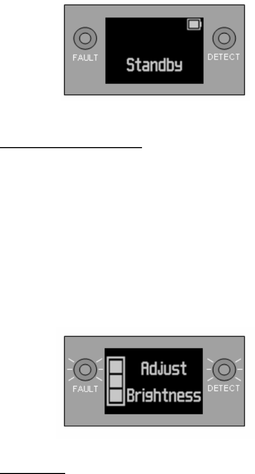
Figure 2-2. Standby Mode Display
2.4 BRIGHTNESS ADJUSTMENT.
After powering on the RANGE-R™ system, it may be necessary to adjust the
brightness of the graphic display and LED indicators for specific operational and
environmental conditions.
a. Press and hold either of the Scan buttons for two seconds to enter ADJUST
BRIGHTNESS Mode (see Figure 2-3).
b. Adjust the brightness by pressing the left-side scan button to decrease the
brightness or the right-side button to increase the brightness.
c. To return to STANDBY Mode, press and release both scan buttons
simultaneously. The selected brightness level is stored in flash memory and
will be used again at the next power-on.
Figure 2-3. Adjust Brightness Display
2.5 SCAN MODE.
WARNING
When the degraded breather detection indicator is illuminated on the
display, only large body movements will be detected. Small body
movements such as respirations may not be detected. This should
be taken into account when making mission oriented operational
decisions. Failure to follow this warning could result in death or
injury.
8
WARNING
It is essential that the operator remain as still as possible when
performing scanning operations in order to achieve the best
overall detection performance. Failure to follow this caution
could result in false alarms and degraded detection performance.
WARNING
There is a region above the display marked “Sensor Area – Do Not
Block.” This region should not be covered by the operator’s hand.
This region houses an antenna used to sense and reject nuisance
detections that may arise from operator-side motion. Failure to do
so could result in false alarms and degraded detection performance.
a. Follow the steps below when performing scanning operations with the
RANGE-R™ system.
b. With the unit in STANDBY Mode, place the black, backside surface firmly
against the wall to be scanned.
c. Squeeze-and-hold both scan buttons to initiate SCAN Mode.
d. Allow three seconds for the signal processing algorithms to assess the
ambient conditions of the room being scanned.
e. Continue to maintain both scan buttons depressed and the system
maintained with the black backside surface firmly against the wall. A scan
indicator located in the upper left corner of the display provides a visual cue
to the operator when the three-second initialization period has ended and full
performance scanning has begun. During the initialization period, the scan
indicator shows only the word “SCAN.” Thereafter, scan bars are added,
slowly cycling through zero, one, two, three, and four bars (see Figure 2-4).
f. When a target is detected, the two horizontal bars in the range field will be
replaced with the range to the target which is displayed to the nearest foot
along with the target classification: “Mov” (Mover) or “Br” (Breather). The
blue DETECT light is also illuminated for the duration of the detection (see
Figure 2-4).
g. Releasing the two Scan buttons will return the system to STANDBY Mode.
9
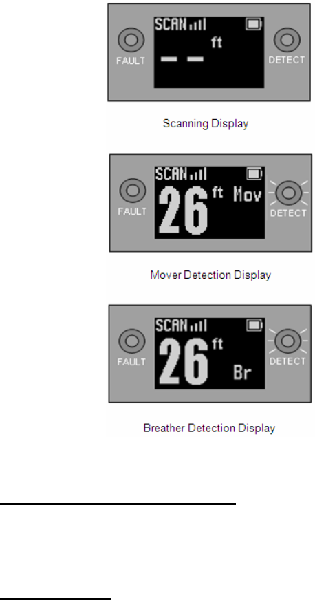
Figure 2-4. Scan Mode Displays
2.6 FACTORS AFFECTING DETECTION.
Several different factors and environmental conditions may inhibit or degrade the
detection capabilities of the RANGE-R™ system. Operators should be familiar with
these limitations prior to using the system.
2.6.1 INTERFERENCE.
WARNING
When the degraded breather detection indicator is illuminated on the
display, only large body movements will be detected. Small body
movements such as respirations may not be detected. This should
be taken into account when making mission oriented operational
decisions. Failure to follow this warning could result in death or
injury.
Strong RF interference will degrade target detection performance. As Breather target
signals are typically much smaller than Mover target signals, Breather detection
10

performance will be affected first. Signal processing algorithms are included to
detect and alert the operator when these conditions exist.
While operating in Scan Mode and with strong interference detected, the display will
show a dimly illuminated Breather symbol overlaid with a circle-cross out (see Figure
2-5). When the degraded detection performance indicator is illuminated, the operator
and surrounding personnel should try scanning again while standing as still as
possible, and if necessary, move to a different spot on the wall where the interference
may be less intense.
2.6.2 Operator and Rearward Motion.
WARNING
When the degraded breather detection indicator is illuminated on the
display, only large body movements will be detected. Small body
movements such as respirations may not be detected. This should
be taken into account when making mission oriented operational
decisions. Failure to follow this warning could result in death or
injury.
The RANGE-R™ system is highly sensitive to motion, whether it is by a person
hiding in a building, or by the operator and his/her teammates. While the majority of
radar energy is directed away from the operator side of the unit, some energy does
bounce back off internal wall structures and is reflected by the operator and anyone
else nearby which is in turn detected by the RANGE-R™ system. Because the
operator is typically the closest person to the system, the radar energy reflected by
the operator is potentially greater than the radar energy returning from a distant
target. For this reason, the operator and his/her teammates must stand as still as
possible during operations in the scan mode.
A rearward looking antenna is included in the design to detect operator motion and
inhibit the resulting false target alerts. However, this does not reduce the strong
interference from the operator that can obscure true target returns. Most of the
degradation in detection performance will be associated with Breather targets as both
the operator’s and the target’s breathing signatures are virtually identical.
While operating in Scan Mode and with operator interference detected, the display
will show a dimly illuminated Breather symbol overlaid with a circle-cross out (see
Figure 2-5). When the degraded detection performance indicator is illuminated, the
operator and surrounding personnel should try scanning again while standing as still
as possible, and if necessary, move to a different spot on the wall where the
interference may be less intense.
11
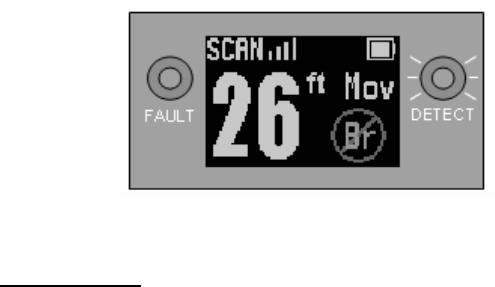
Figure 2-5. Diminished Breather Detection Display
2.6.3 Wall Blockage.
WARNING
To avoid possible wall blockage scenarios, an operator must observe
the building material to avoid scanning through metal or absorptive
material. The building material should be taken into account when
making mission oriented operational decisions. Failure to follow this
warning could result in death or injury.
Wall blockage occurs when a large reflective object is within, or in close proximity to,
the wall being scanned and obscures the view of the target area. The RANGE-R™
system contains signal processing algorithms that detect and alert the operator if
such conditions exist. Since it is possible that the transmit signal is being blocked
and not reaching potential targets, target detection is not possible when blockage is
detected.
While operating in Scan Mode and with blockage detected, the red FAULT light will
be illuminated and the word “Blocked” will be displayed (see Figure 2-6). If this
occurs, the operator should release the scan buttons, move to a different spot on the
wall, and try again.
In some situations, a blockage alert will not be indicated even though the signal is
blocked. One possible is when the unit is held up directly against a metal door or
wall. In this situation, the transmit signal is completely blocked and little to no energy
reaches the receive antenna. Because the blockage signal power threshold will not
be exceeded, no alert is generated. Another scenario occurs when the wall material
is highly absorptive. Here, signal returns from the obscuring object are greatly
reduced by losses in the wall. The blockage signal power threshold is not exceeded
and no alert is generated.
Through training and frequent use in different scenarios with different wall types and
materials, the operator will become aware of its limitations and proficient at adapting
his/her tactics and procedures to reduce the risk of a missed detection.
12
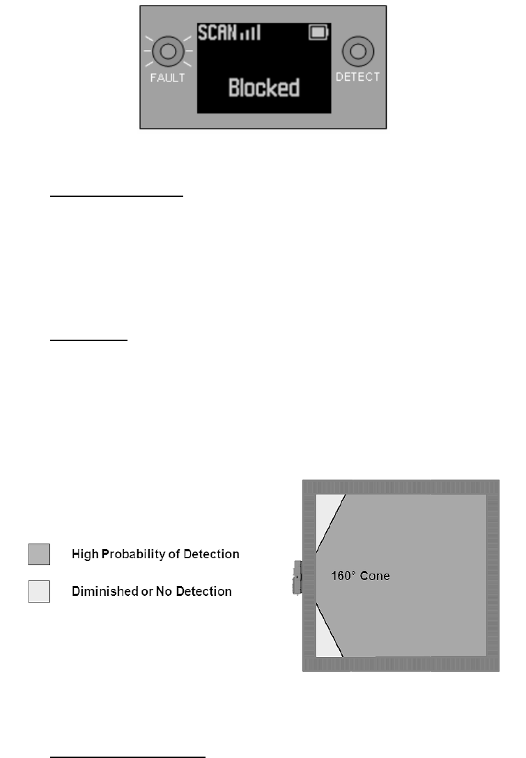
Figure 2-6. Blocked Detection Display
2.6.4 Water and Moisture. Water is highly absorptive at the frequency band in
which the RANGE-R™ system operates. This becomes a factor when the wall being
scanned is made of a porous material such as exposed concrete or adobe and is
saturated deep within from rain or some other source of moisture. In this case,
significant radar energy may be lost due to attenuation through the wall and result in
critical loss of detection performance. There is no system test available for this
condition and thus the operator must be aware of this possibility and trained to
recognize such conditions.
2.6.5 Blind Spots. The best detection performance when using the RANGE-R™
system occurs directly in front of the unit, and extends out ±80 degrees in a conical
pattern (160 degree cone). Outside this region, detection performance rapidly falls
off to a minimum at ±90 degrees. Because of this, there are blind spots in close
proximity and at sharp angles from the system (see Figure 2-7). To compensate for
blind spots, it is suggested that the operator perform scans through at different
locations along the wall surface to maximize scan coverage of the target area.
Figure 2-7. Blind Spots
2.6.6 False Range Indication. Specific building structures may cause the range
to the target to appear farther away than the actual range to the target. This often
occurs in buildings that have a mix of hard and soft walls on the interior, like concrete
13

block or brick and drywall, or half height walls. This may cause the radar to bounce
multiple times and the range that is shown on the RANGE-R™ is then the sum of all
of the reflections. When this happens it is likely that the range will alternate between
the correct range and the incorrect range. In this case RANGE-R™ is still operating
as it should and will continue to detect personnel targets properly.
2.6.7 Hollow Building Materials. Hollow concrete block and similar materials
having hollow cavities present additional challenges to the system. Signal reflections
off internal structures, being close to the radar, can produce strong returns that
desensitize the receiver and degrade detection performance. It is also possible the
return is large enough to be classified as blockage and be indicated as such on the
display.
Reflections off internal wall structures also exaggerate the effects of interference from
movement by the operator and others in close proximity. Higher false alarms, as well
as degraded Breather detection performance due to operator-side movement, have
been observed during operational testing. Minimizing movement on the operator side
of the unit is imperative to achieving the best overall system performance.
2.7 FAULT AND STATUS MODES
Internal circuitry monitors the battery voltage whenever the RANGE-R™ system is
powered on and the critical performance parameters while the unit is actively
transmitting. When a failure occurs or the status changes, indicators are given to the
operator as to the condition of the system.
2.7.1 Battery Status. While the system is powered on, internal circuitry measures
the battery voltage and reports the status to the user. Three different battery status
modes may be displayed:
FULL BATTERY – The battery voltage is sufficient to provide full operational
performance. This state is indicated by a filled-in battery symbol located in the upper
right-hand corner of the graphics display (see Figure 2-8).
LOW BATTERY CAUTION – The battery voltage is beginning to get low, but will
continue to function normally. The operator should consider replacing the batteries
as soon as possible. This state is indicated by an empty battery symbol located in
the upper right-hand corner of the graphics display (see Figure 2-8).
LOW BATTERY WARNING – The battery voltage is too low to continue operation.
The operator must replace the batteries. The words “Replace Battery” are displayed
and the red FAULT light is illuminated.
14
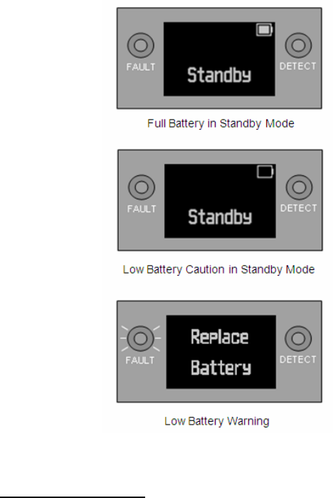
Figure 2-8. Battery Status Displays
2.7.2 Built-In-Test Failures. Continuous built-in-test (CBIT) circuitry monitors
critical performance parameters while the unit is actively transmitting. These
parameters include transmit (Tx) output power, phase locked loop (PLL) lock status,
and software execution status. When these failures occur, the red FAULT light is
illuminated and a description of the failure is shown on the display (see Figure 2-9).
When a PLL Lock failure or a Tx Power failure occurs, releasing the scan buttons and
re-squeezing may solve the problem. If the failure continues after several cycles of
releasing and re-squeezing the scan buttons, the unit should be considered
inoperable.
If a software execution error occurs, the unit will be rebooted within 2 seconds, and
the System Restarted warning will be displayed. The unit will then be in standby
mode, and normal operation can resume.
15
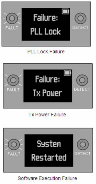
Figure 2-9. Fault Displays
16

CHAPTER 3
MAINTENANCE AND SUPPORT
SECTION I - INSPECTIONS AND STORAGE
3.1 INSPECTIONS.
A proper inspection program that includes preventative checks and maintenance will
help prevent damage and extend the service life of the RANGE-R™ system.
Inspections should be performed both prior to operations and after the completion of
operations.
3.1.1 Preoperational Checks. Prior to conduction operations, the following
checks should be performed to ensure that the RANGE-R™ system is serviceable
and mission ready.
a. Inspect the RANGE-R™ system’s housing and graphics display for visible
physical damage.
b. Ensure the batteries to be used contain a sufficient charge to last the
duration of the mission.
c. Power on the RANGE-R™ system and ensure that both LED indicator lights
illuminate and the graphics display functions properly.
d. Test the RANGE-R™ system on a wall in a safe area with a target at a
known distance to ensure it is functioning properly.
3.1.2 Post Operational Checks. After the completion of an operation, the
following checks and maintenance should be performed to maintain the operational
readiness of the RANGE-R™ system.
a. Inspect the RANGE-R™ system’s housing and graphics display for visible
physical damage
b. Clean the RANGE-R™ housing using either a dry or slightly dampened cloth.
Never use any cleaners or solvents.
c. Clean the graphics display using an approved lens cleaning cloth.
d. Remove the batteries from the system. The system should never be stored
with batteries inserted into the system.
17

3.2 STORAGE.
WARNING
If the RANGE-R™ system is placed in the case with a side facing up,
the scan buttons may be pressed when the case is closed, causing
the unit to transmit. This will drain the batteries and may cause the
system to overheat. This may possibly damage the device.
When not in use, the RANGE-R™ system should be stored in the storage case
provided with the system to protect the system from accidental damage. The system
should be stored with the graphics display facing up. The batteries should also be
removed from the battery compartment to prevent possible damage from battery
leakage.
18

19
SECTION II - SERVICE AND SUPPORT
3.3 SERVICE / WARRANTY.
The manufacturer warranty provided with the RANGE-R™ is for defects in materials
and workmanship for a period of 12 months following delivery to the end user.
Damage due to abuse, misuse, mishandling, or use other than specified in this user
manual is not covered by the warranty. The RANGE-R™ batteries must be removed
from the unit prior to storage. Damage to the RANGE-R™ from leaking batteries is
not covered by the warranty. If your RANGE-R™ requires service, please contact a
product support representative using the contact information listed below to obtain a
Return Material Authorization (RMA) number and shipping instructions.
Service/Warranty Returns:
Phone: 407-517-6110
Email: RANGE-R.service@L-3com.com
3.4 TECHNICAL SUPPORT.
Technical support for the RANGE-R™ is available at anytime. Please feel free to
contact a product support representative with any questions or concerns using the
contact information listed below.
24/7 Technical Support:
Phone: 407-517-6167
Email: RANGE-R.techsupport@L-3com.com