L3 Technologies AISA1 Shipboard use User Manual ProTec AIS Hardware Install Operation Manual
L-3 Communications Shipboard use ProTec AIS Hardware Install Operation Manual
manual
P/N: 165M0014-10Dec. 01/06
Initial Issue
ProTec
AUTOMATIC IDENTIFICATION SYSTEM
HARDWARE
AIS PART NUMBER
AISA1000-10
INSTALLATION AND OPERATION MANUAL

Marine Systems
Aviation Recorders
Initial Issue
Dec. 01/06
165M0014-10
Page ii
AIS Hardware I&O Manual 165M0014-10
Initial Issue
Dec. 01/06
EXPORT CONTROL STATEMENT AIS TECHNOLOGY / DATA:
“This Automatic Identification System (AIS) Products/Technology is
being exported from the United States in accordance with the Export
Administration Regualtions (ECCN #7E994, #4E992), No License Re-
quired (NLR). Diversion contrary to U.S. law is prohibited. In accor-
dance with U.S. Law (Title 15 CFR Part 746 and Supplement No. 1 to
Part 774; and Title 31 CFR) resale/reexport or transfer to certain des-
ignated countries is prohibited without the prior written consent of
the U.S. Department of Commerce.”
This manual contains date sensitive information.
To verify the latest revision level of this manual,
visit our document download site at
http://www.L-3ar.net.
ECopyright 2006 by L-3 Communications.
All rights reserved. No part of this manual may be re-
produced or utilized in any form or by any means, elec-
tronic or mechanical, including photocopying, record-
ing, or by information storage and retrieval system,
without permission in writing.
Inquiries should be addressed to:
L-3 Communications
Aviation Recorders Publications
Vendor Code: 06141
P. O. Box 3041
Sarasota, Florida 34230
Phone: (941) 371–0811
FAX: (941) 377–5591

Marine Systems
Aviation Recorders
Initial Issue
Dec. 01/06
165M0014-10
Page iii
GENERAL
This product and related documentation must be reviewed for familiarization with safety
markings and instructions before operation.
This board was constructed in an ESD (electroćstatic discharge) protected environment. This is
because most of the semiconductor devices used in this board are susceptible to damage by static
discharge.
Depending on the magnitude of the charge, device substrates can be punctured or destroyed by
contact or mere proximity of a static charge. The results can cause degradation of device perforĆ
mance, early failure, or immediate destruction.
These charges are generated in numerous ways such as simple contact, separation of materials,
and normal motions of persons working with static sensitive devices.
When handling or servicing equipment containing static sensitive devices, adequate precautions
must be taken to prevent device damage or destruction.
Only those who are thoroughly familiar with industry accepted techniques for handling static senĆ
sitive devices should attempt to service circuitry with these devices.
In all instances, measures must be taken to prevent static charge buildćup on work surfaces and
persons handling the devices.

Marine Systems
Aviation Recorders
Initial Issue
Dec. 01/06
165M0014-10
Page iv
RETURN MATERIAL POLICY
Components and spare parts purchased from L–3 that are discrepant for any of the following reasons may be re-
turned immediately provided the extended value of the parts are in excess of $100.00.
1. Overshipments
Quantity of parts received in excess of quantity specified on purchase order.
2. Wrong Part Numbers
Receipt of parts numbered other than those identified on a customer order where L–3 has not advised the cus-
tomer by purchase order acknowledgment, by telex, or by notification on the shipping document that the received
part is a replacement for the ordered part.
3. Parts Nonconforming to Specifications
If the extended value of the items is less than $100.00, the items are to be scrapped instead of returned. When
this occurs, notification must be sent to L–3 advising: (1) the reason for the rejection; (2) the items are less than
$100.00 in extended value and have been scrapped, and; (3) whether credit or replacement is desired.
If you wish to return material to L–3 for reasons other than warranty returns or those specified above, please contact
an L–3 Account Administrator for authorization before proceeding. A Return Authorization Number will be assigned at
this time. Your request should specify the relevant Return Authorization Number, purchase order number, part num-
ber, quantity and the reason you wish the part returned.
To assist us in processing these items more efficiently, we ask that all returned goods be accompanied by paperwork
that clearly indicates the following:
1. Reason for return.
2. Purchase Order Numbers.
3. Correspondence Reference Number.
4. Return Authorization Number.
4. Copies of returned goods paperwork should be mailed to:
L–3 COMMUNICATIONS CORPORATION
AVIATION RECORDERS DIVISION
P. O. Box 3041
Sarasota, FL 34230–3041
Attn: Tom Meloche / Marine Systems Product Support Department
5. Parts returned under the above conditions should be addressed to:
L–3 COMMUNICATIONS CORPORATION
AVIATION RECORDERS DIVISION
6000 E. Fruitville Road
Sarasota, FL 34232
Attn: SERVICE DEPARTMENT
Component and spare parts purchased from L–3 that have been on the customer’s shelf for more than 10 weeks from
date of receipt; have been installed in a component or on a vessel, are not covered by this procedure. Such parts
may be covered by warranty in which case they should be returned through normal warranty channels.

Marine Systems
Aviation Recorders
Initial Issue
Dec. 01/06
165M0014-10
Page v
RETURN OF MATERIAL UNDER WARRANTY
1. Material should be returned to the following address:
L–3 COMMUNICATIONS CORPORATION
AVIATION RECORDERS DIVISION
6000 E. Fruitville Road
Sarasota, FL 34232
Attn: WARRANTY RETURNS
2. For returning overseas shipments, the following customs broker must be used:
L–3 COMMUNICATIONS CORPORATION
AVIATION RECORDERS DIVISION
c/o A.J. Arango
Air Cargo Bldg.
Hoover Blvd.
Tampa Int’l Airport
Tampa, Florida 33634
Tel: (813) 248–9220
Fax: (813) 248–6013
To ensure prompt handling of material returned under warranty, your return order and shipment should clearly
identify the item as a warranty return, and a copy of such return order should accompany the shipment. Status of
warranty in process will be provided by the Warranty Administrator.
3. Warranty claims and warranty return orders pertaining to components and spare parts returned should be
mailed to the following address:
L–3 COMMUNICATIONS CORPORATION
AVIATION RECORDERS DIVISION
P. O. Box 3041
Sarasota, FL 34230–3041
Attn: Marine Systems Warranty Administrator
Tel: (941) 377–5574
Fax: (941) 377–5591
RETURNED GOODS
Goods returned to stock for credit at the request of the Buyer and authorized by the Seller, will be subject to a restock-
ing charge of 10% of the purchase price if notified within 30 days of the order, and 25% of the purchase price if notified
after 30 days of the order.
CANCELLATION CHARGE
Any order wishing to be canceled must be approved by the pertinent Account Administrator and may be accountable
for a cancellation fee of 15%. This cancellation fee shall take into account expenses already incurred and commit-
ments made by L–3.

Marine Systems
Aviation Recorders
Initial Issue
Dec. 01/06
165M0014-10
Page vi
THIS PAGE IS INTENTIONALLY LEFT BLANK.

Marine Systems
Aviation Recorders
Initial Issue
Dec. 01/06
165M0014-10
Page vii
TABLE OF CONTENTS
AUTOMATIC IDENTIFICATION SYSTEM
SUBJECT/DESCRIPTION PAGE
SECTION 1 – ProTec AIS Introduction
1.1. General 1–3. . . . . . . . . . . . . . . . . . . . . . . . . . . . . . . . . . . . . . . . . . . . . . . . . . . . . . . . . . . . . . . . .
1.1.1. System Overview 1–3. . . . . . . . . . . . . . . . . . . . . . . . . . . . . . . . . . . . . . . . . . . . . . . . . . . . . . . . .
1.1.2. References 1–4. . . . . . . . . . . . . . . . . . . . . . . . . . . . . . . . . . . . . . . . . . . . . . . . . . . . . . . . . . . . . .
1.1.3. Acronyms 1–5. . . . . . . . . . . . . . . . . . . . . . . . . . . . . . . . . . . . . . . . . . . . . . . . . . . . . . . . . . . . . . .
1.2. Technical Specifications 1–6. . . . . . . . . . . . . . . . . . . . . . . . . . . . . . . . . . . . . . . . . . . . . . . . . . .
1.3. AIS Description 1–8. . . . . . . . . . . . . . . . . . . . . . . . . . . . . . . . . . . . . . . . . . . . . . . . . . . . . . . . . .
1.3.1. Compact Design 1–8. . . . . . . . . . . . . . . . . . . . . . . . . . . . . . . . . . . . . . . . . . . . . . . . . . . . . . . . .
1.3.2. Integral Minimum Keyboard Display (MKD) 1–8. . . . . . . . . . . . . . . . . . . . . . . . . . . . . . . . . .
1.3.3. Integral GPS 1–8. . . . . . . . . . . . . . . . . . . . . . . . . . . . . . . . . . . . . . . . . . . . . . . . . . . . . . . . . . . . .
1.3.4. Data Interface 1–8. . . . . . . . . . . . . . . . . . . . . . . . . . . . . . . . . . . . . . . . . . . . . . . . . . . . . . . . . . .
1.3.5. Equipment List 1–9. . . . . . . . . . . . . . . . . . . . . . . . . . . . . . . . . . . . . . . . . . . . . . . . . . . . . . . . . . .
1.3.6. Operational Modes 1–10. . . . . . . . . . . . . . . . . . . . . . . . . . . . . . . . . . . . . . . . . . . . . . . . . . . . . .
1.3.6.1 Autonomous and Continuous 1–10. . . . . . . . . . . . . . . . . . . . . . . . . . . . . . . . . . . . . . . . . . . . .
1.3.6.2 Assigned 1–10. . . . . . . . . . . . . . . . . . . . . . . . . . . . . . . . . . . . . . . . . . . . . . . . . . . . . . . . . . . . . . .
1.3.6.3 Polled 1–10. . . . . . . . . . . . . . . . . . . . . . . . . . . . . . . . . . . . . . . . . . . . . . . . . . . . . . . . . . . . . . . . . .
1.3.6.4 Initialization 1–10. . . . . . . . . . . . . . . . . . . . . . . . . . . . . . . . . . . . . . . . . . . . . . . . . . . . . . . . . . . . .
1.3.7. DSC Functionality 1–11. . . . . . . . . . . . . . . . . . . . . . . . . . . . . . . . . . . . . . . . . . . . . . . . . . . . . . .
1.3.8. AIS Broadcast Parameters 1–11. . . . . . . . . . . . . . . . . . . . . . . . . . . . . . . . . . . . . . . . . . . . . . .
1.3.9. AIS Frequencies 1–12. . . . . . . . . . . . . . . . . . . . . . . . . . . . . . . . . . . . . . . . . . . . . . . . . . . . . . . .
1.3.10. AIS Input Sentences 1–12. . . . . . . . . . . . . . . . . . . . . . . . . . . . . . . . . . . . . . . . . . . . . . . . . . . . .
1.4. Interface Description 1–13. . . . . . . . . . . . . . . . . . . . . . . . . . . . . . . . . . . . . . . . . . . . . . . . . . . . .
1.4.1. Pilot Systems Input Data and Formats 1–13. . . . . . . . . . . . . . . . . . . . . . . . . . . . . . . . . . . . .
1.4.2. Pilot Systems Output Data and Formats 1–14. . . . . . . . . . . . . . . . . . . . . . . . . . . . . . . . . . . .
1.4.3. Pilot Input / Output Port 1–14. . . . . . . . . . . . . . . . . . . . . . . . . . . . . . . . . . . . . . . . . . . . . . . . . .
1.4.4. Long Range Equipment Interface 1–15. . . . . . . . . . . . . . . . . . . . . . . . . . . . . . . . . . . . . . . . .
1.4.5. Long Range Input Data and Formats 1–16. . . . . . . . . . . . . . . . . . . . . . . . . . . . . . . . . . . . . .
1.4.6. Long Range Output Data and Formats 1–17. . . . . . . . . . . . . . . . . . . . . . . . . . . . . . . . . . . . .

Marine Systems
Aviation Recorders
Initial Issue
Dec. 01/06
165M0014-10
Page viii
TABLE OF CONTENTS
(Continued)
SUBJECT/DESCRIPTION PAGE
1.4.7. Sensor Input Data and Formats 1–19. . . . . . . . . . . . . . . . . . . . . . . . . . . . . . . . . . . . . . . . . . .
1.5. Data Field Assignments 1–19. . . . . . . . . . . . . . . . . . . . . . . . . . . . . . . . . . . . . . . . . . . . . . . . . .
1.5.1. GPS and Sensor Input Sentences 1–19. . . . . . . . . . . . . . . . . . . . . . . . . . . . . . . . . . . . . . . . .
1.5.1.1 DTM – Datum Reference 1–19. . . . . . . . . . . . . . . . . . . . . . . . . . . . . . . . . . . . . . . . . . . . . . . . .
1.5.1.2 GBS – GNSS Satellite Fault Detection 1–20. . . . . . . . . . . . . . . . . . . . . . . . . . . . . . . . . . . . .
1.5.1.3 GGA – Global Positioning System Fix Data 1–20. . . . . . . . . . . . . . . . . . . . . . . . . . . . . . . . .
1.5.1.4 GLL – Geographic Position – Latitude / Longitude 1–20. . . . . . . . . . . . . . . . . . . . . . . . . . .
1.5.1.5 GNS – GNSS Fix Data 1–21. . . . . . . . . . . . . . . . . . . . . . . . . . . . . . . . . . . . . . . . . . . . . . . . . . .
1.5.1.6 HDT – Heading True 1–21. . . . . . . . . . . . . . . . . . . . . . . . . . . . . . . . . . . . . . . . . . . . . . . . . . . . .
1.5.1.7 RMC – Recommended Minimum Specific GNSS Data 1–21. . . . . . . . . . . . . . . . . . . . . . .
1.5.1.8 ROT – Rate of Turn 1–22. . . . . . . . . . . . . . . . . . . . . . . . . . . . . . . . . . . . . . . . . . . . . . . . . . . . . .
1.5.1.9 VBW – Dual Ground / Water Speed 1–22. . . . . . . . . . . . . . . . . . . . . . . . . . . . . . . . . . . . . . . .
1.5.1.10 VTG – Course Over Ground and Ground Speed 1–22. . . . . . . . . . . . . . . . . . . . . . . . . . . .
1.5.1.11 ZDA – Time and Date 1–23. . . . . . . . . . . . . . . . . . . . . . . . . . . . . . . . . . . . . . . . . . . . . . . . . . . .
1.5.2. AIS Specific Input Sentences 1–23. . . . . . . . . . . . . . . . . . . . . . . . . . . . . . . . . . . . . . . . . . . . .
1.5.2.1 ABM – Addressed Binary and Safety–Related Message 1–23. . . . . . . . . . . . . . . . . . . . . .
1.5.2.2 ACA – AIS Regional Channel Assignment Message 1–24. . . . . . . . . . . . . . . . . . . . . . . . .
1.5.2.3 ACK – Acknowledge Alarm 1–24. . . . . . . . . . . . . . . . . . . . . . . . . . . . . . . . . . . . . . . . . . . . . . .
1.5.2.4 AIQ – Query Sentence 1–24. . . . . . . . . . . . . . . . . . . . . . . . . . . . . . . . . . . . . . . . . . . . . . . . . . .
1.5.2.5 AIR – AIS Interrogation Request 1–25. . . . . . . . . . . . . . . . . . . . . . . . . . . . . . . . . . . . . . . . . .
1.5.2.6 BBM – Broadcast Binary Message 1–25. . . . . . . . . . . . . . . . . . . . . . . . . . . . . . . . . . . . . . . .
1.5.2.7 SSD – Ship Static Data 1–25. . . . . . . . . . . . . . . . . . . . . . . . . . . . . . . . . . . . . . . . . . . . . . . . . .
1.5.2.8 VSD – Voyage Static Data 1–26. . . . . . . . . . . . . . . . . . . . . . . . . . . . . . . . . . . . . . . . . . . . . . . .
SECTION 2 – ProTec AIS Operation
2.1. Operation 2–3. . . . . . . . . . . . . . . . . . . . . . . . . . . . . . . . . . . . . . . . . . . . . . . . . . . . . . . . . . . . . . .
2.1.1. Minimum Keyboard Display 2–3. . . . . . . . . . . . . . . . . . . . . . . . . . . . . . . . . . . . . . . . . . . . . . . .
2.1.1.1 Power/Dim Control 2–4. . . . . . . . . . . . . . . . . . . . . . . . . . . . . . . . . . . . . . . . . . . . . . . . . . . . . . .
2.1.1.2 Liquid Crystal Display 2–4. . . . . . . . . . . . . . . . . . . . . . . . . . . . . . . . . . . . . . . . . . . . . . . . . . . . .
2.1.1.3 Key Pad 2–4. . . . . . . . . . . . . . . . . . . . . . . . . . . . . . . . . . . . . . . . . . . . . . . . . . . . . . . . . . . . . . . . .

Marine Systems
Aviation Recorders
Initial Issue
Dec. 01/06
165M0014-10
Page ix
TABLE OF CONTENTS
(Continued)
SUBJECT/DESCRIPTION PAGE
2.1.1.4 Pilot Port 2–4. . . . . . . . . . . . . . . . . . . . . . . . . . . . . . . . . . . . . . . . . . . . . . . . . . . . . . . . . . . . . . . .
2.1.2. Keypad Description 2–4. . . . . . . . . . . . . . . . . . . . . . . . . . . . . . . . . . . . . . . . . . . . . . . . . . . . . . .
2.1.3. Data Display Screens 2–6. . . . . . . . . . . . . . . . . . . . . . . . . . . . . . . . . . . . . . . . . . . . . . . . . . . . .
2.1.3.1 NAV Display Screen (Default Screen) 2–6. . . . . . . . . . . . . . . . . . . . . . . . . . . . . . . . . . . . . . .
2.1.3.2 Own Ship Information 2–7. . . . . . . . . . . . . . . . . . . . . . . . . . . . . . . . . . . . . . . . . . . . . . . . . . . . .
2.1.4. Data Entry Screens 2–8. . . . . . . . . . . . . . . . . . . . . . . . . . . . . . . . . . . . . . . . . . . . . . . . . . . . . . .
2.1.4.1 AIS Main System Menu 2–8. . . . . . . . . . . . . . . . . . . . . . . . . . . . . . . . . . . . . . . . . . . . . . . . . . .
2.1.4.2 Logon / Logoff Screen 2–9. . . . . . . . . . . . . . . . . . . . . . . . . . . . . . . . . . . . . . . . . . . . . . . . . . . .
2.1.4.3 System Information and Configuration 2–11. . . . . . . . . . . . . . . . . . . . . . . . . . . . . . . . . . . . .
2.1.4.4 Vessel/Voyage Setup 2–13. . . . . . . . . . . . . . . . . . . . . . . . . . . . . . . . . . . . . . . . . . . . . . . . . . . .
2.1.4.5 Channel Management 2–16. . . . . . . . . . . . . . . . . . . . . . . . . . . . . . . . . . . . . . . . . . . . . . . . . . .
2.1.4.6 Antenna Position 2–17. . . . . . . . . . . . . . . . . . . . . . . . . . . . . . . . . . . . . . . . . . . . . . . . . . . . . . . .
2.1.4.7 Text Messaging 2–19. . . . . . . . . . . . . . . . . . . . . . . . . . . . . . . . . . . . . . . . . . . . . . . . . . . . . . . . .
2.1.4.8 View Safety Text Log 2–20. . . . . . . . . . . . . . . . . . . . . . . . . . . . . . . . . . . . . . . . . . . . . . . . . . . .
2.1.4.9 Change Password 2–21. . . . . . . . . . . . . . . . . . . . . . . . . . . . . . . . . . . . . . . . . . . . . . . . . . . . . . .
2.1.4.10 System Alert Screen 2–22. . . . . . . . . . . . . . . . . . . . . . . . . . . . . . . . . . . . . . . . . . . . . . . . . . . . .
2.1.4.11 Alarm Status 2–22. . . . . . . . . . . . . . . . . . . . . . . . . . . . . . . . . . . . . . . . . . . . . . . . . . . . . . . . . . . .
2.1.4.12 General Status Screen 2–25. . . . . . . . . . . . . . . . . . . . . . . . . . . . . . . . . . . . . . . . . . . . . . . . . . .
2.1.4.13 Down–Time Log 2–27. . . . . . . . . . . . . . . . . . . . . . . . . . . . . . . . . . . . . . . . . . . . . . . . . . . . . . . . .
2.1.4.14 LCD Viewing Angle Adjustment 2–27. . . . . . . . . . . . . . . . . . . . . . . . . . . . . . . . . . . . . . . . . . .
2.1.4.15 Baud Rate Setup 2–28. . . . . . . . . . . . . . . . . . . . . . . . . . . . . . . . . . . . . . . . . . . . . . . . . . . . . . . .
2.1.4.16 Set AIS Channels 2–29. . . . . . . . . . . . . . . . . . . . . . . . . . . . . . . . . . . . . . . . . . . . . . . . . . . . . . .
SECTION 3 – ProTec AIS Installation
3.1. Installation 3–3. . . . . . . . . . . . . . . . . . . . . . . . . . . . . . . . . . . . . . . . . . . . . . . . . . . . . . . . . . . . . . .
3.1.1. Transponder 3–4. . . . . . . . . . . . . . . . . . . . . . . . . . . . . . . . . . . . . . . . . . . . . . . . . . . . . . . . . . . . .
3.1.2. Connecting the IEC Data Interface Cable 3–6. . . . . . . . . . . . . . . . . . . . . . . . . . . . . . . . . . . .
3.1.2.1 Data Channels 3–6. . . . . . . . . . . . . . . . . . . . . . . . . . . . . . . . . . . . . . . . . . . . . . . . . . . . . . . . . . .
3.1.2.2 Data Cable 3–7. . . . . . . . . . . . . . . . . . . . . . . . . . . . . . . . . . . . . . . . . . . . . . . . . . . . . . . . . . . . . .
3.1.2.3 Terminal Block 3–7. . . . . . . . . . . . . . . . . . . . . . . . . . . . . . . . . . . . . . . . . . . . . . . . . . . . . . . . . . .

Marine Systems
Aviation Recorders
Initial Issue
Dec. 01/06
165M0014-10
Page x
TABLE OF CONTENTS
(Continued)
SUBJECT/DESCRIPTION PAGE
3.1.3. Installing the VHF Antenna 3–13. . . . . . . . . . . . . . . . . . . . . . . . . . . . . . . . . . . . . . . . . . . . . . .
3.1.4. Installing the GPS Antenna 3–14. . . . . . . . . . . . . . . . . . . . . . . . . . . . . . . . . . . . . . . . . . . . . . .
3.1.5. PowerUp and Configuration 3–17. . . . . . . . . . . . . . . . . . . . . . . . . . . . . . . . . . . . . . . . . . . . . .
3.1.5.1 PowerUp the Transponder 3–17. . . . . . . . . . . . . . . . . . . . . . . . . . . . . . . . . . . . . . . . . . . . . . . .
3.1.5.2 Vessel / Voyage Setup 3–18. . . . . . . . . . . . . . . . . . . . . . . . . . . . . . . . . . . . . . . . . . . . . . . . . . .
3.1.5.3 Antenna Position Configuration 3–22. . . . . . . . . . . . . . . . . . . . . . . . . . . . . . . . . . . . . . . . . . .
3.1.5.4 Verify Transponder Linkup to Ship’s dGPS & GYRO 3–23. . . . . . . . . . . . . . . . . . . . . . . . .
SECTION 4 – ProTec AIS Installation
LIST OF APPENDIXES
APPENDIX TITLE PAGE
APPENDIX A – ProTec AIS Installation Checklist

Marine Systems
Aviation Recorders
Initial Issue
Dec. 01/06
165M0014-10
Page xi
LIST OF FIGURES
FIGURE TITLE PAGE
Figure 1–1. AIS Transponder 1–6. . . . . . . . . . . . . . . . . . . . . . . . . . . . . . . . . . . . . . . . . . . . . . . . . . . .
Figure 2–1. AIS Transponder 2–3. . . . . . . . . . . . . . . . . . . . . . . . . . . . . . . . . . . . . . . . . . . . . . . . . . . .
Figure 2–2. NAV Display Screens 2–6. . . . . . . . . . . . . . . . . . . . . . . . . . . . . . . . . . . . . . . . . . . . . . . . .
Figure 2–3. Own Ship Data Display 2–7. . . . . . . . . . . . . . . . . . . . . . . . . . . . . . . . . . . . . . . . . . . . . . .
Figure 2–4. AIS Main System Menu 2–9. . . . . . . . . . . . . . . . . . . . . . . . . . . . . . . . . . . . . . . . . . . . . . .
Figure 2–5. Password Entry Screen 2–11. . . . . . . . . . . . . . . . . . . . . . . . . . . . . . . . . . . . . . . . . . . . . .
Figure 2–6. System Information and Configuration Screen 2–12. . . . . . . . . . . . . . . . . . . . . . . . . .
Figure 2–7. Vessel Data Setup 2–14. . . . . . . . . . . . . . . . . . . . . . . . . . . . . . . . . . . . . . . . . . . . . . . . . .
Figure 2–8. Channel Management Settings Screen 2–17. . . . . . . . . . . . . . . . . . . . . . . . . . . . . . . .
Figure 2–9. Antenna Position Screen 2–17. . . . . . . . . . . . . . . . . . . . . . . . . . . . . . . . . . . . . . . . . . . .
Figure 2–10. Antenna Position Measurements 2–18. . . . . . . . . . . . . . . . . . . . . . . . . . . . . . . . . . . . .
Figure 2–11. Safety Text Message 2–20. . . . . . . . . . . . . . . . . . . . . . . . . . . . . . . . . . . . . . . . . . . . . . . .
Figure 2–12. Safety Text Review Screen 2–21. . . . . . . . . . . . . . . . . . . . . . . . . . . . . . . . . . . . . . . . . . .
Figure 2–13. Password Change Screen 2–22. . . . . . . . . . . . . . . . . . . . . . . . . . . . . . . . . . . . . . . . . . .
Figure 2–14. System Alert Screen 2–22. . . . . . . . . . . . . . . . . . . . . . . . . . . . . . . . . . . . . . . . . . . . . . . .
Figure 2–15. Alarm Status Screen 2–23. . . . . . . . . . . . . . . . . . . . . . . . . . . . . . . . . . . . . . . . . . . . . . . .
Figure 2–16. General Status Screen 2–25. . . . . . . . . . . . . . . . . . . . . . . . . . . . . . . . . . . . . . . . . . . . . .
Figure 2–17. Down–Time Log Screen 2–27. . . . . . . . . . . . . . . . . . . . . . . . . . . . . . . . . . . . . . . . . . . . .
Figure 2–18. LCD Viewing Angle Adjust Screen 2–28. . . . . . . . . . . . . . . . . . . . . . . . . . . . . . . . . . . .
Figure 2–19. Baud Rate Setup Screen 2–28. . . . . . . . . . . . . . . . . . . . . . . . . . . . . . . . . . . . . . . . . . . .
Figure 2–20. AIS Channel Setup Screen 2–29. . . . . . . . . . . . . . . . . . . . . . . . . . . . . . . . . . . . . . . . . .
Figure 3–1. AIS Transponder Interconnection Diagram 3–3. . . . . . . . . . . . . . . . . . . . . . . . . . . . . .
Figure 3–2. AIS Transponder IEC Data Cable 3–8. . . . . . . . . . . . . . . . . . . . . . . . . . . . . . . . . . . . . .
Figure 3–3. IEC Data Cable External Wiring Diagram 3–9. . . . . . . . . . . . . . . . . . . . . . . . . . . . . . .
Figure 3–4. AIS Transponder Power Cable 3–11. . . . . . . . . . . . . . . . . . . . . . . . . . . . . . . . . . . . . . .
Figure 3–5. Pilot Port Cable 3–12. . . . . . . . . . . . . . . . . . . . . . . . . . . . . . . . . . . . . . . . . . . . . . . . . . . . .
Figure 3–6. AIS Transponder Antenna Diagram 3–15. . . . . . . . . . . . . . . . . . . . . . . . . . . . . . . . . . .
Figure 3–7. AIS Transponder Rear View 3–16. . . . . . . . . . . . . . . . . . . . . . . . . . . . . . . . . . . . . . . . . .
Figure 3–8. AIS Transponder MKD 3–17. . . . . . . . . . . . . . . . . . . . . . . . . . . . . . . . . . . . . . . . . . . . . .
Figure 3–9. UAIS Main System Menu 3–19. . . . . . . . . . . . . . . . . . . . . . . . . . . . . . . . . . . . . . . . . . . .
Figure 3–10. Vessel/Voyage Setup 3–20. . . . . . . . . . . . . . . . . . . . . . . . . . . . . . . . . . . . . . . . . . . . . . . .
Figure 3–11. Antenna Position 3–22. . . . . . . . . . . . . . . . . . . . . . . . . . . . . . . . . . . . . . . . . . . . . . . . . . .

Marine Systems
Aviation Recorders
Initial Issue
Dec. 01/06
165M0014-10
Page xii
LIST OF FIGURES
(Continued)
FIGURE TITLE PAGE
Figure 3–12. Calculating Antenna Position 3–22. . . . . . . . . . . . . . . . . . . . . . . . . . . . . . . . . . . . . . . . .
Figure 4–1. AIS Transponder O&D Drawing with Trunion Bracket 4–3. . . . . . . . . . . . . . . . . . . . .
Figure 4–2. AIS Transponder O&D Drawing 4–4. . . . . . . . . . . . . . . . . . . . . . . . . . . . . . . . . . . . . . . .
Figure 4–3. IEC Data Cable Interconnect Diagram 4–5. . . . . . . . . . . . . . . . . . . . . . . . . . . . . . .
LIST OF TABLES
TABLE TITLE PAGE
Table 1–1. AIS Parts List 1–9. . . . . . . . . . . . . . . . . . . . . . . . . . . . . . . . . . . . . . . . . . . . . . . . . . . . . . .
Table 1–2. Pilot System High–Speed Input Data Formats 1–13. . . . . . . . . . . . . . . . . . . . . . . . . .
Table 1–3. Pilot System High–Speed Output Data Formats 1–14. . . . . . . . . . . . . . . . . . . . . . . .
Table 1–4. Pilot Port Pinout 1–15. . . . . . . . . . . . . . . . . . . . . . . . . . . . . . . . . . . . . . . . . . . . . . . . . . . .
Table 1–5. Long Range Input Data and Formats 1–16. . . . . . . . . . . . . . . . . . . . . . . . . . . . . . . . . .
Table 1–6. Long Range Output Data and Formats 1–18. . . . . . . . . . . . . . . . . . . . . . . . . . . . . . . .
Table 1–7. Sensor Input Data and Formats 1–19. . . . . . . . . . . . . . . . . . . . . . . . . . . . . . . . . . . . . .
Table 2–1. ProTec AIS Default Passwords 2–10. . . . . . . . . . . . . . . . . . . . . . . . . . . . . . . . . . . . . . .
Table 2–2. Password Type Menu Screen Access 2–10. . . . . . . . . . . . . . . . . . . . . . . . . . . . . . . . .
Table 2–3. Vessel Type Codes 2–15. . . . . . . . . . . . . . . . . . . . . . . . . . . . . . . . . . . . . . . . . . . . . . . . .
Table 2–4. Integrity Alarm Conditions Signalled Using ALR Sentence Formatter 2–24. . . . . .
Table 2–5. Sensor Status Indications Signalled Using TXT Sentence Formatter 2–26. . . . . .
Table 3–1. Data Channels 3–6. . . . . . . . . . . . . . . . . . . . . . . . . . . . . . . . . . . . . . . . . . . . . . . . . . . . . .
Table 3–2. IEC Cable Pinouts 3–10. . . . . . . . . . . . . . . . . . . . . . . . . . . . . . . . . . . . . . . . . . . . . . . . . .
Table 3–3. Pilot Port Pinout 3–12. . . . . . . . . . . . . . . . . . . . . . . . . . . . . . . . . . . . . . . . . . . . . . . . . . . .
Table 3–4. ProTec AIS Default Passwords 3–18. . . . . . . . . . . . . . . . . . . . . . . . . . . . . . . . . . . . . . .
Table 3–5. Vessel Type Codes 3–21. . . . . . . . . . . . . . . . . . . . . . . . . . . . . . . . . . . . . . . . . . . . . . . . .

Marine Systems
Aviation Recorders
Initial Issue
Dec. 01/06
165M0014-10
Page 1–1
SECTION 1
ProTec
AUTOMATIC IDENTIFICATION SYSTEM (AIS)
INTRODUCTION

Marine Systems
Aviation Recorders
Initial Issue
Dec. 01/06
165M0014-10
Page 1–2
THIS PAGE IS INTENTIONALLY LEFT BLANK.

Marine Systems
Aviation Recorders
Initial Issue
Dec. 01/06
165M0014-10
Page 1–3
ProTec AIS Introduction
1.1. General
The L-3 ProTec is an Automatic Identification System transponder which is fully com-
pliant to the technical specifications defined by the IMO and outlined in ITU.R.M
1371-1. The transponder employs the latest radio frequency and SOTDMA and DSC
controller technology to provide a high performance, automated, and reliable identifi-
cation system for commercial mariners. The Transponder is a fully automated sys-
tem which ties into ship’s navigational instruments to provide automatic transmission
of ships identity, status, and maneuvering intentions via standard marine VHF com-
munication techniques. Sequencing of transmission between all vessels within VHF
range is provided through SOTDMA controlling software to handle high traffic vol-
ume situations.
The Transponder is a fully automated system. This means that once it is installed
and turned on, no maintenance is required to keep it operational. The only time the
user needs to perform any function on the transponder is to change the ship’s Ves-
sel/Voyage data as required.
1.1.1. System Overview
The L-3 ProTec is an Automatic Identification System fully compliant with the IMO
specifications defined in IMO MSC.74(69) Annex 3, IEC 61993-2, and ITU.R
M.1371-1. This AIS transponder has been developed using technology applied in
the design of our VHF DSC Class A radio, a design which has been field tested for
over a decade with over 10000 units operational in the field. With the addition of the
SOTDMA controllers, the L-3 ProTec provides a cost-effective AIS solution which will
meet the needs of any vessel required to carry AIS. The compact, single-box design
allows the L-3 ProTec to be easily incorporated into any bridge layout thus simplify-
ing installation and cabling requirements.
The L-3 ProTec has been designed as maintenance-free unit which makes extensive
use of surface mount technology (SMT). The repair of printed wiring assemblies
(PWAs) containing SMT components requires specialized factory equipment, train-
ing, and techniques, therefore, such PWAs are not field-repairable.
As a result, maintenance philosophy for the L-3 ProTec is replacement of failed as-
semblies. In the case of the L-3 ProTec, the replaceable assemblies are the Face-
plate Assembly (192M0093-00), the Main PWA (205M0023-12), the Channel 70
PWA (205M0003-01), the IEC PWA (205M0274-11), and the Controller PWA
(205M0307-01).

Marine Systems
Aviation Recorders
Initial Issue
Dec. 01/06
165M0014-10
Page 1–4
When it has been determined that one or more of these assemblies is faulty, the
faulty assembly(ies) should be removed and returned to the Aviation Recorders fac-
tory for repair or replacement. Attempts to repair any of these assemblies will void
the warranty. Extreme care should be used when handling these assemblies.
For repair service, ship units to:
L-3 Communications, Aviation Recorders
6000 East Fruitville Road
Sarasota, FL 34232 USA
Attn: Repair Department
Tel: (941) 377-5558
Fax #: (941) 377-5585
CAUTION: THE L-3 ProTec CIRCUIT BOARDS ARE SUSCEPTIBLE TO
ELECTROSTATIC DESTRUCTION (ESD). PRIOR TO HANDLING
PWAs, ENSURE PROPER PERSONNEL GROUNDING TECH-
NIQUES ARE USED. ENSURE THAT CARDS ARE PLACED INTO
STATIC SHIELDING CONDUCTIVE BAGS WHEN HANDLING OR
STORING.
1.1.2. References
IMO Resolution MSC.74(69), Annex 3, Recommendation on Performance Standards
for an Universal Shipborne Automatic Identification Systems (AIS)
IMO SN/Circ. 227, Guidelines for the INstallation of a Shipborne Automatic Identifi-
cation System (AIS)
International Telecommunications Union Sector for Radio Communications (ITU-R)
Recommendation M.1371-1, Technical Characteristics for a Universal Shipborne Au-
tomatic Identification System Using Time Division Multiple Access in the Maritime
Mobile Band.
IEC 61993-2 Edition1, Maritime Navigation and Radiocommunication Requirements
- Automatic Identification Systems (AIS) - Part 2: Class A shipborne Equipment of
the Universal Automatic Identification System (AIS) - Operational and Performance
Requirements, Methods of Test and Required Test Results
IEC 60945 Edition 4, Maritime Navigation and Radiocommunication Equipment and
Systems - General Requirements - Methods of Testing and Required Test Results.
IALA Recommendation on AIS Shore Stations and Networking Aspects Relating to
the AIS Service, Edition 1.0, September 5, 2002

Marine Systems
Aviation Recorders
Initial Issue
Dec. 01/06
165M0014-10
Page 1–5
IEC 61162-1 Edition 1.0, Maritime Navigation and Radiocommunication Equipment
and Systems - Digital Interfaces - Part 100: Single Talker and Multiple Listeners
IEC 61162-2 Edition 1.0, Maritime Navigation and Radiocommunication Equipment
and Systems - Digital Interfaces - Part 100: Single Talker and Multiple Listeners,
High-Speed Transmissions
1.1.3. Acronyms
ABM Addressed Binary Message
ABK Acknowledgement Message
ACA AIS Channel Assignment
ACK Ackowledgement Message
ASPA Automatic Radar Plotting Aid
BBM Broadcast Binary Message
COG Course Over Ground
DGPS Differential Global Positioning System
GGA Global Positioning Fix Data
GLL Geographic Position, Latitude/Longitude
GNSS Global Navigation Satellite System
GPS Global Positioning System
GSA GPS DOP and Active Satellites
GSV GPS Satellites in View
HDG Heading, Deviation & Variation
HDT Heading, True
IEC International Electrotechnical Commission
IMO International Maritime Organization
LRF Long Range Function
LFI Long Range Interrogation
MMSI Maritime Mobile Service ID
NMEA National Marine Electronics Association
RAIM Receiver Autonomous Integrity Monitoring
RMC Recommended Minimum Data for GPS
ROT Rate of Turn
SOG Speed Over Ground
SOTDMA Self Organized Time Division Multiple Access
SSD Station Static Data
TDS Target Display Software
TXT Status/Indication Message
VBW Dual Ground/Water Speed
VDL VHF Data-link Other Vessel Message
VDM VHF Data-link Message
VDO VHF Data-link Own-vessel Message
VSD Voyage Static Data
VTG Track Made Good and Ground Speed
ZDA Date and Time
Marine Systems
Aviation Recorders
Initial Issue
Dec. 01/06
165M0014-10
Page 1–6
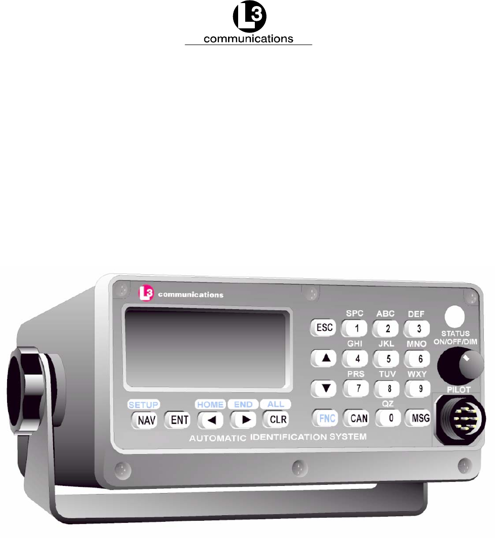
NOTE: 1. Front Panel Mating Connectors
Pilot Port - L3 PN: 063-98-02113
TYCO PN: 206485-1
communications
STATUS
ON/OFF/DIM
PILOT
Figure 1–1. AIS Transponder
1.2. Technical Specifications
Standards IMO MSC.74(69) Annex 3, IEC 61993-2 Ed. 1, ITU.R.M.1371-1
Ship reporting capacity
2250 reports per minute, 4500 reports per minute on two channels
TDMA Transmitter
TX Frequency: 156.025 MHz - 162.025 MHz, manual/automatic setting
Transmitter Power: 2 W, 12.5 W manual/automatic selection
TDMA Receiver
RX Frequency: 156.025 MHz - 162.025 MHz, 2 channels
RX1: Default CH87B (161.975 MHz), manual/automatic setting
RX2: Default CH88B (162.025 MHz), manual/automatic setting
Channel Spacing: 25 kHz and 12.5 kHz
DSC Receiver
RX Frequency: CH70 (156.525 MHz)

Marine Systems
Aviation Recorders
Initial Issue
Dec. 01/06
165M0014-10
Page 1–7
Internal GPS Receiver
12 Channel, UTC Synchronization Jitter: ±100 ms
[Time between slot start and transmitter on.]
Navigational data
COG/SOG, ROT, POS, Heading from external sources
Display
Integral MKD with 160 x 64 Dots backlit LCD
INTERFACE
Input ABM, ACA, ACK, AIR, BBM, DTM, GBS, GGA, GLL, GNS, HDT,
OSD, SSD, RMC, ROT, VBW, VSD, VTG
Output ABK, VDO, VDM, ACA, ACS, ALR, LRF, LR1, LR2, LR3, TXT
Power Supply
24 VDC nominal, complies with IEC 60945 Ed. 4
NOTE: Due to the stringent transmit attack and release times spe-
cified in ITU 1371, a robust power source is required for
proper operation. Recommended current ratings for power
sources are:
24 VDC - 10 Amps
The transponder may operate improperly if the power
source does not have the recommended minimum current
ratings.
Environment
IEC 60945 Ed. 4 for Protected Environment
Frequency
VHF Marine Band

Marine Systems
Aviation Recorders
Initial Issue
Dec. 01/06
165M0014-10
Page 1–8
1.3. AIS Description
1.3.1. Compact Design
The completely self-contained L-3 ProTec is the most compact AIS unit available on
the market today with outside dimensions of 6.5” W (16.5 cm.) x 3.4” H (8.6 cm.) x
7.4” D (18.8 cm.). It is easily mounted on any surface using either a trunion bracket
or flush-mount bracket. The data port on the faceplate provides for easy connection
to any external display in either mounting configuration.
1.3.2. Integral Minimum Keyboard Display (MKD)
In line with the compact design, the L-3 ProTec is a single-box design incorporating
an integral MKD which is fully IMO compliant. The interface includes a 2.58” L (6.5
cm.) x 1.16” H (2.9 cm.) (160 x 64 Dots) backlit LCD screen for displaying alphanu-
meric text and a multifunction keypad. The closest three vessels within AIS range
will be displayed with each vessel identified by MMSI and ship name and will display
both range and bearing to each vessel.
The interface has been designed to facilitate data entry and retrieval with a minimum
of keystrokes. It also includes a Pilot port designed to allow any user to quickly and
easily attach a portable AIS-compatible display system directly to the AIS transpond-
er for display of the AIS data. This display system can consist of any system which
recognizes the NMEA AIS string whether it’s installed on a handheld PC, laptop PC,
or dedicated display.
1.3.3. Integral GPS
The L-3 ProTec includes an internal GPS receiver card. The internal GPS provides
timing data required for synchronization of transmission. By specifications, ship posi-
tional information in NMEA format is to be fed to the transponder from the ships ex-
ternal electronic position indicating system through the supplied data cable. The in-
ternal GPS requires a dedicated GPS antenna to be mounted on the superstructure
and the appropriate connections are supplied on the transponder unit back panel.
1.3.4. Data Interface
Each transponder will be delivered with an IEC-specified NMEA standard data cable
required to interface to ship’s sensors and external display. The description of this
interface cable is given in the Installation Section of this manual. The standard kit
includes an eight (8) ft. (2.9 meters) cable and a terminal block to facilitate the final
linkup to the ship’s navigational instruments.

Marine Systems
Aviation Recorders
Initial Issue
Dec. 01/06
165M0014-10
Page 1–9
1.3.5. Equipment List
The Standard AIS Installation Kit includes the following equipment:
FTransponder Unit
FFlush Mount Kit
FTrunion Mount Kit
FIEC NMEA Data Cable
FTerminal Strips (Qty: 3)
FPower Cable
FGround Cable
FInstallation Manuals
In order to complete the installation, the following items will be required.
FGPS Antenna with coaxial cable
FVHF Antenna with coaxial cable
FGyro Interface (if gyro output is not NMEA)
FDGPS Interface (if ships dGPS output is not NMEA)
Table 1–1. AIS Parts List
Component Part Number
Transponder AISA1000-10
Flush Mount Kit 147M0092-01
Trunion Mount 147M0092-02
IEC Cable 024M0088-00
Terminal Strip 2469800177
422 to 232 Adapter 415-98-00079
Power Cable 024M0086-00
Ground Cable 024M0043-00
Installation Manual 165M0014-00
Quick Installation Manual 165M0511-00

Marine Systems
Aviation Recorders
Initial Issue
Dec. 01/06
165M0014-10
Page 1–10
1.3.6. Operational Modes
The ProTec AIS is designed to operate in each of three modes: Autonomous and
Continuous, Assigned and Polled which are defined below.
1.3.6.1 Autonomous and Continuous
This is the default mode. The ProTec AIS will determine its own schedule for trans-
mission of position and identification and will automatically resolve scheduling con-
flicts with other stations using the Self Organized Time Division Multiple Access
(SOTDMA) methodology.
1.3.6.2 Assigned
The ProTec will automatically switch to assigned mode when it is commanded by a
competent authority, such as a base or repeater station, to transmit on a specific
transmission schedule. In this mode, the ProTec allocates the defined slots and be-
gins transmitting on these slots. It will continue to transmit in these slots with a zero
slot time-out and a zero slot offset, until those slots have been removed from the
transmission schedule. The assigned slots use the SOTDMA access scheme, with
the time-out value set to the assigned slot time-out. The assignment terminates
when the slot time-out reaches zero of any assigned slot, and the ProTec returns to
autonomous and continuous mode.
1.3.6.3 Polled
The ProTec AIS will transmit a response to DSC interrogation messages from a ship
or competent authority and respond back on the same channel without interfering
with either of the other two modes. When an automatic response is required, trans-
mitted responses will be made on channel 70 unless the unit is instructed to transmit
on another channel. The ProTec is inhibited from transmitting on the AIS 1 and AIS
2 channels. If and when frequency channels other than channel 70 are used for
DSC transmissions, the receive capability of TDMA operations should not be
impaired more than it would be if all DSC messages were transmitted on channel
70.
1.3.6.4 Initialization
The ProTec AIS will enter into an Initialization mode at Power-Up during which it will
monitor the TDMA channels for one minute. During this initialization period, a dy-
namic directory of all users in the system will be created which includes user IDs,
slot assignments, positions, and other transmitted data. After this initialization period
of 1 minute, the ProTec will enter the required operational mode and begin transmis-
sion of the AIS data on the required schedule.

Marine Systems
Aviation Recorders
Initial Issue
Dec. 01/06
165M0014-10
Page 1–11
1.3.7. DSC Functionality
The Assigned and Polled operational modes are activated through a DSC message
transmitted by the competent authority. In order to provide for this, the ProTec AIS
contains a dedicated DSC receiver that is tuned to channel 70. DSC messages
originating from shore stations of competent authorities will define regional AIS fre-
quencies, regions of coverage, required transmission schedule and/or interrogation
request. The ProTec AIS will respond back to such DSC interrogations on the fre-
quency specified in a manner such that it does not interfere with the TDMA transmis-
sions by interleaving the transmission between TDMA transmissions. The DSC re-
sponse will be made after a random delay of 0 - 20 secs provided the signaling
channel is clear and the TDMA transmissions are not interrupted.
1.3.8. AIS Broadcast Parameters
A Class A AIS unit broadcasts the following information every 2 to 10 seconds while
underway, and every 3 minutes while at anchor at a power level of 12.5 watts. The
information broadcast includes:
FMMSI number - unique referenceable identification.
FNavigation status
FSpeed over ground - 1/10 knot resolution.
FPosition accuracy - differential GPS.
FLongitude - to 1/10000 minute and Latitude - to 1/10000 minute.
FCourse over ground - relative to true north to 1/10th degree.
FTrue Heading - 0 to 359 degrees derived from heading sensor.
FTime stamp - The universal time to nearest second that this information
was generated.
In addition, the Class A AIS unit broadcasts the following information every 6
minutes:
FMMSI number - same unique identification used above, links the data
above to described vessel.
FIMO number - unique referenceable identification (related to ship’s
construction).
FRadio call sign - international call sign assigned to vessel, often used on
voice radio.
FName - Name of ship, 20 characters are provided.
FType of ship/cargo - there is a table of possibilities that are available.

Marine Systems
Aviation Recorders
Initial Issue
Dec. 01/06
165M0014-10
Page 1–12
FDimensions of ship - to nearest meter.
FLocation on ship where reference point for position reports is located.
FType of position fixing device - various options from differential GPS to un-
defined.
FDraught of ship - 1/10 meter to 25.5 meters [note “air-draught” is not pro-
vided].
FDestination - 20 characters are provided.
1.3.9. AIS Frequencies
The International Telecommunications Union World Radio Conference in 1997 desig-
nated two VHF radio frequencies: 161.975 MHz (AIS1, or channel 87B) and 162.025
MHz (AIS2, or channel 88B) for AIS. In the US, the first channel is owned by Mari-
TEL, a public coast station operator, and the second by the federal government. The
USCG signed a Memorandum of Agreement with MariTEL for use of AIS 1, and has
authority from the National Telecommunications and Information Administration to
use both AIS1 and AIS 2 US-wide for AIS operation. The USCG has asked the Fed-
eral Communications Commission to authorize any US vessel to operate AIS on
these two channels under its existing ship station license. The FCC released a No-
tice authorizing operation of AIS under a ship’s existing station license.
1.3.10. AIS Input Sentences
This section lists the input sentences received by the L-3 ProTec AIS Transponder.
The input sentences are categorized as Pilot, Long Range, and Sensor, which are
listed as follows:
Pilot
ABM, BBM, AIR, VSD, SSD, ACK, ACA, AIQ
Long Range
LRI, LRF
Sensor
RMC, VTG, ROT, HDT, GNS, GLL, GGA, GRS, GSA, GST, GSV, ZDA, GBS, DTM,
VBW

Marine Systems
Aviation Recorders
Initial Issue
Dec. 01/06
165M0014-10
Page 1–13
1.4. Interface Description
1.4.1. Pilot Systems Input Data and Formats
The input data and formats are shown in Table 1–2, and the details of the sentences
can be found in IEC 61162-1.
Table 1–2. Pilot System High-Speed Input Data Formats
Data IEC 61162-1 Sentences
Normal Access - Parameter Entry
Static station information
- (Vessel name)
- (Call sign)
- Antenna location
- Length and beam
SSD - Station Static Data
- (not used, field sets to null by MKD)
- (not used, field sets to null by MKD)
- used to set the antenna location for the
MKD external GPS only (saved in MKD
memory)
Voyage Information
- Vessel type and cargo category
- Navigational status
- Draught, max. actual static
- Destination
- ETA date and time
- Regional application flags
VSD - Voyage Static Data
Long Range Acknowledgement
External manual LR acknowledgement LRF - Long Range Function
Initiate VHF Data Link Broadcasts
Safety messages ABM - Addressed Binary Message
BBM - Broadcast Binary Message
Binary messages ABM - Addressed Binary Message
BBM - Broadcast Binary Message
Interrogation message AIR - AIS Interrogation Information
Channel Setting
Channel assignment message (set frequency) ACA - AIS Channel Assignment Message
BIIT Input
Alarm / indication acknowledgement ACK - Acknowledgement Message
Own Station Settings Queries
Query messages AIQ, ACA - Query AIS Channel Assignment

Marine Systems
Aviation Recorders
Initial Issue
Dec. 01/06
165M0014-10
Page 1–14
1.4.2. Pilot Systems Output Data and Formats
The output data and formats are shown in Table 1–3, and the details of the sen-
tences can be found in IEC 61162-1.
Table 1–3. Pilot System High-Speed Output Data Formats
Data IEC 61162-1 Sentences
Prepared by AIS Transponder
Notification that a session initiated by messages
ABM, BBM, ACA, AIR is terminated
ABK - Acknowledgement Message
AIS Own-ship broadcast data (all transmissions
available)
VDO - VHF Data-link Own-vessel Message
Query response messages ACA - AIS Channel Assignment
SSD - Station Static Data
VSD - Voyage Static Data
BIIT Results
AIS equipment status ALR - Alarm Message
TXT - Status / Indication Message
Received from Long Range Equipment
LR Interrogation LRI - Long Range Interrogation
LR Function identification LRF - Long Range Function
Received on VHF Data Link by AIS Transponder
All VDL AIS messages received
- Broadcast or
- Addressed to own station
VDM - VHF Data Link Message
1.4.3. Pilot Input / Output Port
The Pilot input/output port is a part of the AIS Class A stations. If the installation of
the AIS equipment is such that a pilot cannot connect his Personal Pilot Unit (PPU)
with a reasonable length of cable, an extension cable must be installed with a con-
nector located on the bridge such that the PPU can be connected on the normal
working position of the port.

Marine Systems
Aviation Recorders
Initial Issue
Dec. 01/06
165M0014-10
Page 1–15
The Pilot input/output port defined by IEC 61193-2 for connections of ship’s pilot
equipment shall, if fitted, be connected using the pilot port cable, p/n: 024M0099-03.
The Pilot input/output port meets the requirement of IEC 61162-2 and is terminated
as shown in Table 1–4.
Table 1–4. Pilot Port Pinout
J1 Pin Name Description Pair Color P2 Pin
1 PILOT_TXA RS4–22 Compliant Output A Blue 2
2 GND Signal/Power 0 Volt Reference Black 5
3+ 8V + 8.0 Volt ( 5%) Output Used to Power External
Test Equipment. External Equipment should be
Current Limited to 300mA
4 PILOT_TXB RS–422 Compliant Output B Black 7
5 PILOT_RXA RS–422 Compliant Input A Green 8
6 PILOT_RXB RS–422 Compliant Input B Black 3
7 TRACE/BOOT_TX TTL–Level RS–232 Serial Output (Trace Message/
Bootload Output)
8 RX_SINAD TDMA / DSC FM Discriminator Output used to
Test Receiver Performance during Special Test
Modes.
9NO CONNECT Not Used
NOTE: Some early transponders had incorrect Pilot Port wiring.
See factory for more details.
1.4.4. Long Range Equipment Interface
The range of operation of standard AIS is limited to the range of VHF transmissions
which is approximately 30 miles. The Long Range mode is intended to allow the ex-
change of ships position information from ship to a competent authority via a satellite
interface such as Inmarsat-C which is already onboard many ships. This port is in-
tended to interface with the Long Range equipment.
The Long Range reply can be set in either:
Fautomatic mode (AUTO)
Fmanual mode L-3 ProTec (MANUAL)
Fmanual mode external application (EXT APPL).
The Long Range reply, when in AUTO mode, is made as soon as a request is re-
ceived on the Long Range communication port.

Marine Systems
Aviation Recorders
Initial Issue
Dec. 01/06
165M0014-10
Page 1–16
The Officer of the Watch must approve the Long Range reply when in MANUAL
mode, by a means of pressing a keyboard button on the L-3 ProTec before the reply
is performed.
The Long Range reply, when in EXT APPL mode, is made by the L-3 ProTec upon
reception of confirmation / acknowledgement from the external application via the
high-speed ports. The external application acknowledges the interrogation by return-
ing the LRF sentence (updated with reply information).
1.4.5. Long Range Input Data and Formats
The input data and formats are in the form of two Long Range interrogation sen-
tences, LRI and LRF, refer to Table 1–5.
FThe LRI -sentence contains the information needed to determine if a reply
needs to be constructed.
FThe LRF-sentence identifies the information items that are being re-
quested. Details of each sentence can be found in IEC 61162-1.
Table 1–5. Long Range Input Data and Formats
Data IEC 61162-1 Sentences
Long Range Interrogation
Type of request:
- Geographic area request
- AIS transponder request
LRI - Long Range Interrogation
Long Range Function identification
Requestor MMSI and Name
Request for:
- Ship’s name, call sign and IMO number (A)
- Date and time of message composition (B)
- Position (C)
- Course over ground (E)
- Speed over ground (F)
- Destination and ETA (I)
- Draught (O)
- Ship / Cargo (P)
- Ship’s length, breadth and type (U)
- Number of persons on board (W)
LRF - Long Range Function

Marine Systems
Aviation Recorders
Initial Issue
Dec. 01/06
165M0014-10
Page 1–17
1.4.6. Long Range Output Data and Formats
The output data and formats are in the form of four Long Range reply sentences,
LRF, LR1, LR2, and LR3, refer to Table 1–6.
FThe LRF sentence provides the “Function Reply Status” for the requested
information. Following is a list of “Function Reply Status” characters with
the status:
2 = Information available and provided in the following LR1, LR2, and
LR3 sentences.
3 = Information not available from the AIS system.
4 = Information is available but not provided (i.e. restricted access deter-
mined by ship’s master).
FThe LR1 sentence identifies the destination for the reply and contains the
information items requested by the “A” function identification character in
the LRF sentence.
FThe LR2 sentence contains the information items requested by the “B, C,
E, and F” function identification characters in the LRF sentence.
FThe LR3 sentence contains the information items requested by the “I, O,
P, U, and W” function identification characters in the LRF sentence.

Marine Systems
Aviation Recorders
Initial Issue
Dec. 01/06
165M0014-10
Page 1–18
Table 1–6. Long Range Output Data and Formats
Data IEC 61162-1 Sentences
Long Range Function identification
Requestor MMSI and Name
Request for:
- Ship’s name, call sign and IMO number (A)
- Date and time of message composition (B)
- Position (C)
- Course over ground (E)
- Speed over ground (F)
- Destination and ETA (I)
- Draught (O)
- Ship / Cargo (P)
- Ship’s length, breadth and type (U)
- Number of persons on board (W)
LRF - Long Range Function
MMSI of Responder
MMSI or Requestor
Ship’s name
Ship’s call sign
IMO number
LR1 - Long Range Response, Line 1
MMSI of Responder
Date and time of message composition
Position
Course over ground
Speed over ground
LR2 - Long Range Response, Line 2
MMSI of Responder
Destination and ETA
Draught
Ship / Cargo
Ship’s length, breadth and type
Number of persons on board
LR3 - Long Range Response, Line 3

Marine Systems
Aviation Recorders
Initial Issue
Dec. 01/06
165M0014-10
Page 1–19
1.4.7. Sensor Input Data and Formats
The L-3 ProTec Shipborne Class A Transponder supports input data sentences from
various ship sensors, refer to Table 1–7.
Table 1–7. Sensor Input Data and Formats
Sensor Data IEC 61162-1 Sentences
GNSS Positions system:
- Time of position
- Latitude /Longitude
- Accuracy (and integrity status)
Course Over Ground (COG)
Speed Over Ground (SOG)
RAIM Indicator
DTM, GBS, GGA, GLL, GNS, GRS, GSA,
GST, GSV, HDT, RMC, ROT, VBW, VTG,
ZDA
Log Course Over Ground (COG)
Speed Over Ground (SOG)
VBW
Gyro Heading
Rate of Turn (ROT)
HDT, ROT
1.5. Data Field Assignments
1.5.1. GPS and Sensor Input Sentences
1.5.1.1 DTM - Datum Reference
If Local and Reverence Datum codes are not WGS84, then the positions report from
that sensor is discarded.
Field Notes
Local Datum Code Check for WGS84
Local Datum Subdivision Code Ignored
Lat Offset (2 fields) Ignored
Long Offset (2 fields) Ignored
Altitude Offset Ignored
Reference Datum Code Check for WGS84

Marine Systems
Aviation Recorders
Initial Issue
Dec. 01/06
165M0014-10
Page 1–20
1.5.1.2 GBS - GNSS Satellite Fault Detection
If this sentence is received from the position source, with Latitude error or Longitude
error specified, the RAIM flag will be set to TRUE. If both are Null or 60 seconds
goes by without a GBS sentence, RAIM flag goes to False
Field Notes
UTC Time of GGA or GNS Ignored
Expected Error in Latitude Check for Null
Expected Error in Longitude Check for Null
Expected Error in Altitude Ignored
ID Number of Most LIkely
Failed Satellite Ignored
Probability of MIssed Detection Ignored
Estimate of Bias in Meters Ignored
Standard Deviation of Bias Estimate Ignored
1.5.1.3 GGA - Global Positioning System Fix Data
Field Notes
UTC of Position UTC Second is used to
indicate Time Stamp
Latitude (2 fields) Used
Longitude (2 fields) Used
GPS Quality Indicator Used
Number of Satellites in Use Ignored
Horizontal Dilution of Precision (HDOP) Ignored
Altitude RE: Main Sea Level (2 fields) Ignored
Geoidal Separation (2 fields) Ignored
Age of Diff Data Ignored
Diff Reference Station Ignored
1.5.1.4 GLL - Geographic Position - Latitude / Longitude
Field Notes
Latitude (2 fields) Used
Longitude (2 fields) Used
UTC of Position UTC Second is used to
indicate Time Stamp
Status Used
Mode Indicator Used

Marine Systems
Aviation Recorders
Initial Issue
Dec. 01/06
165M0014-10
Page 1–21
1.5.1.5 GNS - GNSS Fix Data
If the Mode Indicator is a NULL field, the sentence is ignored.
Field Notes
UTC of Position UTC Second is used to
indicate Time Stamp
Latitude (2 fields) Used
Longitude (2 fields) Used
Mode Indicator Used
Total Number of Satellites in Use Ignored
HDOP Ignored
Antenna Altitude Ignored
Geoidal Separation Ignored
Age of Diff Data Ignored
Diff Reference Station ID Ignored
1.5.1.6 HDT - Heading True
Message is ignored if Talker is “HC”.
Field Notes
Heading Used if Valid indicator is “T”
Valid Indicator Used
1.5.1.7 RMC - Recommended Minimum Specific GNSS Data
Field Notes
UTC of Position Fix UTC Second is used to
indicate Time Stamp
Status Must be “A”
Latitude (2 fields) Used
Longitude (2 fields) Used
SOG, knots Used
COG, degrees Used
Date Ignored
Magnetic Variation (2 fields) Ignored
Mode Indicator Used

Marine Systems
Aviation Recorders
Initial Issue
Dec. 01/06
165M0014-10
Page 1–22
1.5.1.8 ROT - Rate of Turn
The rate of turn value is only used if the talker identifier is “TI”. Otherwise the value
will only be used to determine if the vessel is “Moving Right” or “Moving Left”.
Field Notes
Rate of Turn Used when status is “A”. If Talker
is “TI”, value is converted ascending
to 1371 msg 1, 2, 3 spec. If talker is not
“TI”, value is set to - 127, 0, or + 127,
based on ROT value.
Status Must be “A”
1.5.1.9 VBW - Dual Ground / Water Speed
The current position source must be external GPS, and heading must be available
for the transponder to accept this sentence.
Field Notes
Longitudinal Water Speed Ignored
Transverse Water Speed Ignored
Status: Water Speed Ignored
Longitudinal Ground Speed Used if Status is set to “A”
Transverse Ground Speed Used if Status is set to “A“
Status: Ground Speed Used
Stern Transverse Water Speed Ignored
Status Stern Water Speed Ignored
Stern Transverse Ground Speed Ignored
Status Stern Ground Speed Ignored
1.5.1.10 VTG - Course Over Ground and Ground Speed
Field Notes
GOG, degrees True (2 fields) Used
COG, degrees Magnetic (2 fields) Ignored
SOG, knots (2 fields) Used
SOG, km/h (2 fields) Ignored
Mode Indicator Used

Marine Systems
Aviation Recorders
Initial Issue
Dec. 01/06
165M0014-10
Page 1–23
1.5.1.11 ZDA - Time and Date
This message is only processed if it is received from the internal GPS (the time
synchronization source).
Field Notes
UTC Used
Day Used
Month Used
Year Used
Local Zone Hours Ignored
Local Zone Minutes Ignored
1.5.2. AIS Specific Input Sentences
1.5.2.1 ABM - Addressed Binary and Safety-Related Message
Field Notes
Total Number of Sentences Used if in interval 1..9,
otherwise the sentence
is ignored.
Sentence Number Used if in interval 1..total
sentence, otherwise the
sentence is ignored.
Sequential Message Identifier Used if in interval 0..3,
otherwise the sentence
is ignored.
MMSI of Destination Used
AIS Channel Used
Message ID Used if in 6 or 12,
otherwise the sentence
is ignored.
Encapsulated Data Used
Number of Filled Bits Used

Marine Systems
Aviation Recorders
Initial Issue
Dec. 01/06
165M0014-10
Page 1–24
1.5.2.2 ACA - AIS Regional Channel Assignment Message
The zone created of this sentence must be accepted by the channel management
rules (size of zone, distance to own position, etc.) If the zone isn’t accepted, the
zone will be ignored.
Field Notes
Sequence Number Ignored
NE Latitude (2 fields) Used
NE Longitude (2 fields) Used
SW Latitude (2 fields) Used
SW Longitude (2 fields) Used
Transitional Zone Size Used
Channel A Used
Channel A Bandwidth Used
Channel B Used
Channel B Bandwidth Used
Tx/Rx Mode Used
Power Level Used
In Use Flag Ignored
Time of In Use Change Ignored
1.5.2.3 ACK - Acknowledge Alarm
Field Notes
ID of the Alarm Source Used
1.5.2.4 AIQ - Query Sentence
Field Notes
Approved Sentence Formatter of
Data being Requested It is possible to query the
ACA Sentence

Marine Systems
Aviation Recorders
Initial Issue
Dec. 01/06
165M0014-10
Page 1–25
1.5.2.5 AIR - AIS Interrogation Request
Field Notes
MMSI 1 Used
Message ID 1.1 Used
Message Subsection Ignored
Message ID 1.2 Used, may be NULL
Message Subsection Ignored
MMSI 2 Used, may be NULL
Message ID 2.1 Used, may be NULL
Message Sub Section Ignored
1.5.2.6 BBM - Broadcast Binary Message
Field Notes
Total Number of Sentences Used if in interval 1..9,
otherwise rejected.
Sentence Number Used if in interval 1..total
number of sentences,
otherwise rejected.
Sequential Message Identifier Used if in interval 0..9,
otherwise rejected.
AIS Channel Used
Message ID Used if 8 or 14
Encapsulated Data Used
Number of Filled Bits Used
1.5.2.7 SSD - Ship Static Data
Field Notes
Call Sign Ignored, use the proprietary
password protected sentence
instead (used by the MKD)
Name Same as Call Sign
Pos Ref A This is the EXTERNAL
Position reference, use
proprietary sentence for
the internal Position reference.
May be NULL
Pos Ref B Same as Pos Ref A
Pos Ref C Same as Pos Ref A
Pos Ref D Same as Pos Ref A
DTE Used
Source Identifier Ignored

Marine Systems
Aviation Recorders
Initial Issue
Dec. 01/06
165M0014-10
Page 1–26
1.5.2.8 VSD - Voyage Static Data
Field Notes
Type of Ship and Cargo Used
Maximum Present Draught Used
Persons On-Board Used
Destination Used
Estimated UTC of Arrival Used
Estimated Day of Arrival Used
Estimated Month of Arrival Used
Navigational Status Used
Regional Application Flags Used

Marine Systems
Aviation Recorders
Initial Issue
Dec. 01/06
165M0014-10
Page 2–1
SECTION 2
ProTec
AUTOMATIC IDENTIFICATION SYSTEM (AIS)
OPERATION

Marine Systems
Aviation Recorders
Initial Issue
Dec. 01/06
165M0014-10
Page 2–2
THIS PAGE IS INTENTIONALLY LEFT BLANK.
Marine Systems
Aviation Recorders
Initial Issue
Dec. 01/06
165M0014-10
Page 2–3
ProTec AIS Operation
2.1. Operation
The L-3 ProTec has been designed to require minimal user interaction during normal
operation. The interface consists of an integral alphanumeric display with alphanu-
meric keypad providing for data entry, retrieval and display.
2.1.1. Minimum Keyboard Display
The L-3 ProTec includes and integral MKD which is fully IMO compliant. The MKD is
designed to be used for configuration of the hardware, entry of vessel and voyage
specific data, and be used to monitor the AIS system. The MKD provides numerous
functions, which can be accessed via the controls located on the front face of the
ProTec AIS system. The MKD provides a fully functional menu structure that allows
the user to Logon / Logoff , configure System Information, Vessel / Voyage data, and
the Antenna Position. The user may also view Alarm Status, General Status, Down-
Time Log, and the Safety Text Log. In addition, the AIS Channels can be configured,
along with changing user passwords, setting Baud rate, adjust the LCD viewing
angle, and managing the Change Management Settings. The front face of the L-3
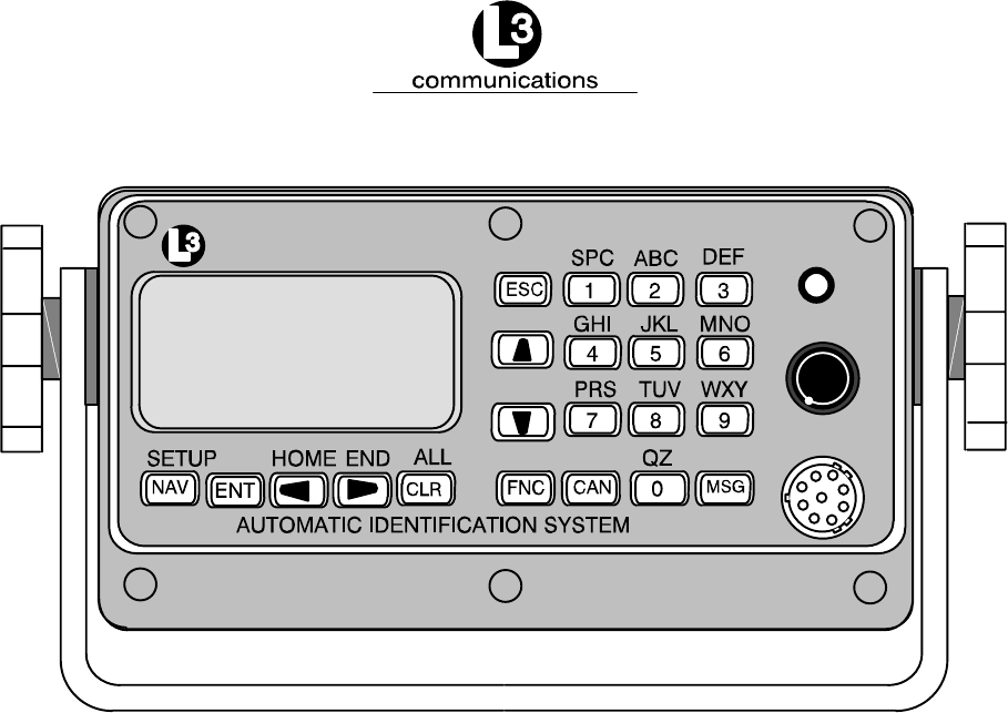
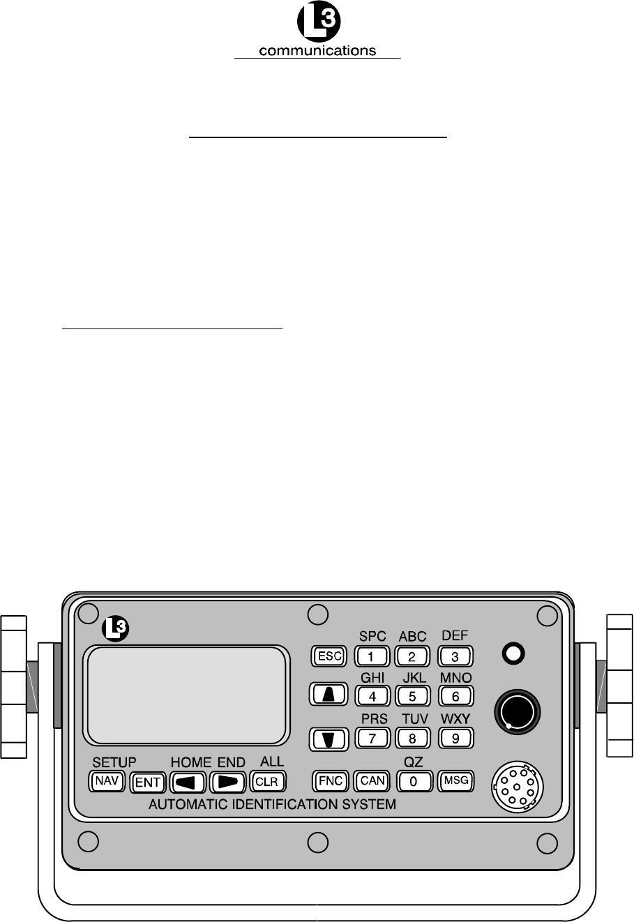
ProTec contains the following controls.
communications
STATUS
ON/OFF/DIM
PILOT
Figure 2–1. AIS Transponder

Marine Systems
Aviation Recorders
Initial Issue
Dec. 01/06
165M0014-10
Page 2–4
NOTE: When the AIS is in operation it is normal for the housing to be
warm to the touch.
2.1.1.1 Power/Dim Control
A single control knob controls both the on/off function and backlighting level for the
LCD. To turn the unit ’On’, rotate the knob clockwise. To turn unit ’Off’ rotate counter-
clockwise fully. The degree of rotation determines the brightness of the LCD back-
light and rotation to the right will dim the backlighting.
2.1.1.2 Liquid Crystal Display
The display is an alphanumeric LCD with backlighting which will display data entry
forms and AIS target data for the nearest three vessels.
2.1.1.3 Key Pad
The keypad contains dedicated function buttons and alphanumeric buttons which
allow for data entry and retrieval.
2.1.1.4 Pilot Port
The Pilot Port is an IEC high speed (38400 Kbs), RS422, data port which can be
used to connect any external display such as an ECS, or other PC-based software
package.
2.1.2. Keypad Description
The keypad allows the user to access the menu system built into the transponder
interface. The keys are defined below:
NAV AIS Target Data Display
Pressing this button will bring the user to the main default screen which
will display the AIS target data for the nearest three vessels, or allows
the user to switch back to the “Own Ship” display if the nearest three
vessels are already displayed.
ENT Enter Key
Allows user to enter Edit mode, or to save data if already performing an
Edit operation.
CLR Clear Key
Used to clear data from a data entry field before entering new data .
Pressing once will clear the entire field.

Marine Systems
Aviation Recorders
Initial Issue
Dec. 01/06
165M0014-10
Page 2–5
Directional ARROW Keys
Used to navigate between data entry fields on a data entry form and
scroll right/left and up/down in an alphanumeric display field. When in
Closest Vessel (default) screen, the Left or Right Arrow Keys will allow
the user to toggle between the Ship Name display and the MMSI
screen. (The MMSI screen will always be displayed for a vessel if the
ship name is not known.
FNC Function Key
Used as the initial key in a key sequence to access the various secon-
dary functions of the interface.
CAN Cancel Key
Used to cancel any edit made in a data entry field and revert data back
to preexisting data.
MSG Message Key
Used to access the text messaging window, in order to send Safety Text
Messages.
ESC Escape Key
Will bring user up one level on the menu system.
The blue text above some of the keys identify the secondary definitions for each but-
ton. These secondary definitions are activated by pressing of the FNC button in a
key sequence.
SETUP Enters the AIS Main System Menu menu system.
HOME Returns cursor to start position in a data entry field
END Moves cursor to last position in a data entry field
ALL System Information Menu
The alphanumeric keypad is used to enter both numbers and letters. When alphanu-
meric text entry is expected, the nonnumerical options are presented before the nu-
meric value of the key. For example, the number “2” key provides for entry of “A”,
“B”, and “C”. When the cursor is positioned in a display field location that expects an
alphanumeric character, the first press of the “2” key will result in the display of an
“A”. Another press (in less than one second) will cause a “B” to be displayed. The
next press shows a “C”, while the forth press shows a “2”.
Marine Systems
Aviation Recorders
Initial Issue
Dec. 01/06
165M0014-10
Page 2–6
Repeated key presses will result in cycling through the character options repeatedly.
When the operator stops pressing keys for longer than the preset timeout, the last
value is retained and the cursor moves to the next location in the field. Pressing a
different key forces acceptance of the last character for the field and moves the cur-
sor along.
FNC-ENT Own Ship display
(NAV Key will also bring up this screen if already showing the Closest
Vessel display.)
2.1.3. Data Display Screens
The AIS interface consists of the following display screens each of which is ac-
cessed using the defined key sequence.
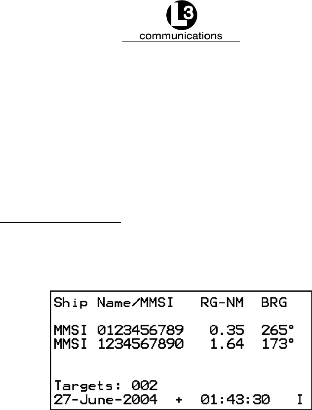
2.1.3.1 NAV Display Screen (Default Screen)
Figure 2–2. NAV Display Screen
MKD will default to this screen after 30 seconds when the unit is idle.
This display shows closest three (3) targets by MMSI number or ship name, the
range in nautical miles, and bearing of each target. Using the up (↑) or down (↓) ar-
row keys you may scroll through every target that is detected.
Targets xxx: Number of targets detected by the transponder.
Date: Current date.
Time: Current time derived by the internal GPS receiver.
GPS status can be found in lower right corner of display.
I = Internal Time: Valid time from the internal GPS (normal operating
condition).
S = Slot Time: Lost internal GPS time but is deriving timing inform–
ation from the slot timing on the VHF Data Link (VDL).
F= Flywheel: Transponder is depending on the internal CPU clock
for timing, after losing internal and slot timing. It will
run for approximately one minute and then go to “N”.
N= No time available
Marine Systems
Aviation Recorders
Initial Issue
Dec. 01/06
165M0014-10
Page 2–7
Text messaging can be disabled by pressing the FNC → 1 button. When text mes-
saging is disabled a “Tx Disabled” message will appear in the upper right hand area
of the display window.
The AIS can be set to use it’s internal GPS by pressing the FNC → 4 button. When
using the internal GPS a “+” symbol will appear in the lower center area of the dis-
play window (as shown in Figure 2–2).
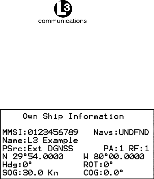
Figure 2–3. Own Ship Data Display
2.1.3.2 Own Ship Information
Press the NAV button repeatedly from any menu to cycle the displays until the Own
Ship Information menu appears. The data that is displayed is as follows:
MMSI: Maritime Mobile Service ID: Nine digit unique identification number
that registers the boat information in the U.S. Coast Guard’s national
distress database for use in emergency situations
NavS: Navigational Status:
UNDFND Undefined
UW-ENG Underway Using Engine
AANCHR At Anchor
NOCMD Not Under Command
RMANUV Restricted Maneuverability
CBDRFT Constrained by Draught
MOORED Moored
AGRND Aground
FISHNG Engaged in Fishing
SAILNG Underway sailing
Name: Vessel Name: Any alphanumeric characters up to 20 in length.
PSrc: Positional Data Source: The following options may be seen in the
order of their priority:

Marine Systems
Aviation Recorders
Initial Issue
Dec. 01/06
165M0014-10
Page 2–8
Ext DGNSS - External GPS in use (corrected).
Int M17Corr - Internal GPS in use (corrected, message 17).
Int Bcncorr - Internal GPS in use (corrected, beacon).
Ext Uncorr - External GPS in use (uncorrected).
Int Uncorr - Internal GPS in use (uncorrected).
No Pos Src - No sensor position in use.
PA: Positional Accuracy: 0 = uncorrected, 1 = corrected.
RF: RAIM Flag: (Receiver Autonomous Integrity Monitoring)
0 = normal operation, 1 = in use.
Lat: Latitude: North or South in degrees.
Lon: Longitude: East or West in degrees.
Hdg: Heading: in degrees true from Gyrocompass.
ROT: Rate of turn: in degrees/sec (- denotes port, + denotes starboard).
COG: Course Over Ground: in degrees true from dGPS.
SOG: Speed Over Ground: in knots from dGPS.
2.1.4. Data Entry Screens
The AIS interface provides the following three data entry screens for completing in-
put of required vessel and voyage data and for modifying the administrator pass-
word. The required data entry screen can be accessed from the main AIS Main Sys-
tem Menu menu. This menu is accessed by the key sequence FNC SETUP. The re-
quired screen can be selected by using the DOWN / UP arrow keys to scroll through
the list and pressing ENT to select the highlighted screen name. This will open and
display the screen and free all fields for editing.
Use the LEFT, RIGHT, UP, DOWN arrows to navigate between fields. Use the ENT
key to select a field to edit. Use the alphanumeric keypad to enter the required data
into the field. Use ENT to save the data entered into the field. Use CAN to cancel
any changes made to edited fields and revert to preexisting data. Once the data
entry is completed, pressing ESC will exit the user to the AIS Main System Menu
screen, allowing the user to go to another menu selection.
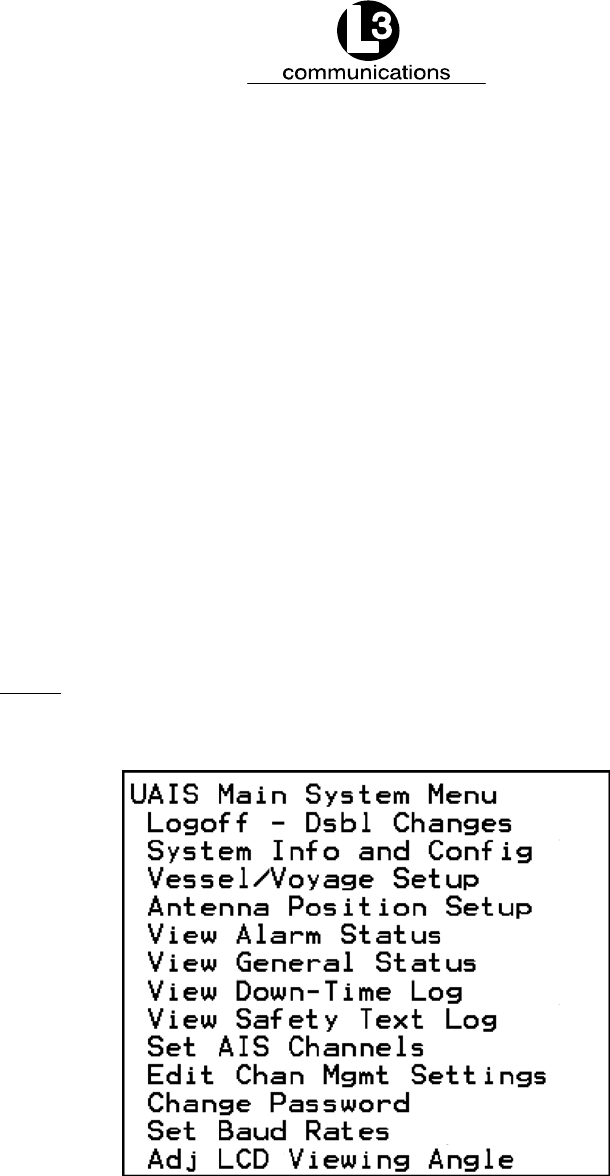
2.1.4.1 AIS Main System Menu
Press FNC → NAV button from any menu to access this screen.
The AIS Main System Menu contains the following options:
Marine Systems
Aviation Recorders
Initial Issue
Dec. 01/06
165M0014-10
Page 2–9
FLogon / Logoff
FSystem Information and Config
FVessel / Voyage Setup
FAntenna Position Setup
FView Alarm Status
FView General Status
FView Down-Time Log
FView Safety Text Log
FSet AIS Channels
FEdit Channel Mgmt Settings
FChange Password
FSet Baud Rates
FLCD Viewing Angle
NOTE: Figure 2–4 shows the AIS Main System Menu screen as it
appears as the user initially enters this menu. Not shown is
the Logon option.
Figure 2–4. AIS Main System Menu
2.1.4.2 Logon / Logoff Screen
Passwords allow the user to change the information contained within the AIS Trans-
ponder. Users with an Administrative password can change any of the information
contained within the AIS Transponder; however, users with a User password, cannot

Marine Systems
Aviation Recorders
Initial Issue
Dec. 01/06
165M0014-10
Page 2–10
change the MMSI number, IMO number, Name of the ship, Call Sign, passwords, or
anything contained in the Channel management screen.
Press FNC → NAV button from any menu and use the up (↑) or down (↓) arrow
keys.
This screen will appear prior to entry of any menu besides the NAV menu. After en-
tering the proper password, press ESC to continue.
Table 2–1. ProTec AIS Default Passwords
Default Passwords
Administrative L3AIS
User L3USR
Table 2–2. Password Type Menu Screen Access
Menu Item Read Access Write Access Comments
Logon - Password Entry G, U, A G, U, A
System Info and Config G, U, A A
Vessel/Voyage Setup G, U, A U, A Update of MMSI, IMO No,
Call Sign, and Name of
Ship Limited to A
Antenna Position Setup G, U, A A
View Alarm Status G, U, A Not Applicable
View General Status G, U, A Not Applicable
View Down-Time Log G, U, A Not Applicable
View Safety Text Log G, U, A Not Applicable
Set AIS Channels G, U, A A
Edit Chan Mgmt Settings G, U, A U, A
Change Password G, U, A A
Set Baud Rates G, U, A A
Adj LCD Viewing Angle G, U, A A
(G)eneral Access, (U)ser Access, (A)dmin Access

Marine Systems
Aviation Recorders
Initial Issue
Dec. 01/06
165M0014-10
Page 2–11
To log on perform the following:
(1) Press the FNC key.
(2) Press the NAV key. The AIS Main System Menu screen will appear.
(3) Select Logon, and press the ENT key. The System Password Entry screen will
appear.
(4) Press the ENT key, and enter the password, and press the ENT again.
(5) Press the ESC key to return to the AIS Main System Menu screen.
To log off from any menu other than the UAIS Main System menu perform the
following:
(1) Press the FNC key.
(2) Press the NAV key. The AIS Main System Menu screen will appear.
(3) Select Logoff, and press the ENT key. The user is now logged off of the AIS
Transponder.
Figure 2–5. Password Entry Screen
2.1.4.3 System Information and Configuration
Press FNC → CLR button from any menu.
Powerup: Number of power ups and length of current power up.
ChkSums: Checksums of internal processors. Used for information and
troubleshooting.
NOTE: To be compatible with older versions of NMEA 0183 (ver-
sion 1.X and lower) the checksum requirement must be dis-
abled. This can be done by setting the ChksmRqd (Check-
sum Required) field to “NO” by using the up and down ar-
rows.

Marine Systems
Aviation Recorders
Initial Issue
Dec. 01/06
165M0014-10
Page 2–12
SW Rev: Software Revision of transponder.
Pwd Rqrd: Password required. Determines whether or not a password is
required at power up.
Al Popup: Alarm Popups. Yes = popups enabled, No = disabled.
Scrn Tmt: Screen Timeout. Yes = default to NAV screen after 30 seconds,
No = disable
LR RsPns: Long Range Response. All long range requests cause an alarm to be
displayed.
IEC Trc: IEC Trace. Turns on up to five levels of troubleshooting messages,
0 = off.
VDL Trc: VDL Trace. Turns on up to five levels of troubleshooting messages,
0 = off.
To enter System Information and Configuration information, perform the fol-
lowing:
(1) Press the FNC key, press the NAV key. The AIS Main System Menu screen will
appear.
(2) Using the down Arrow key, select System Info and Config, and press the ENT
key. (Refer to Figure 2–6.)
(3) Using the arrow keys, highlight an entry point, and press the ENT key.
(4) Enter the data by using the arrow keys, press the ENT key, and move to the
next data entry point.
(5) Press the ESC key to return to the AIS Main System Menu screen.
Figure 2–6. System Information and Configuration Screen

Marine Systems
Aviation Recorders
Initial Issue
Dec. 01/06
165M0014-10
Page 2–13
2.1.4.4 Vessel/Voyage Setup
The Vessel/Voyage Setup screen allows the user to enter the following information,
which is required to be completed during the installation of the AIS.
MMSI: Maritime Mobile Service ID: Maximum nine (9) numbers.
NavS: Navigational Status:
UNDFND Undefined
UW-ENG Underway Using Engine
AANCHR At Anchor
NOCMD Not Under Command
RMANUV Restricted Maneuverability
CBDRFT Constrained by Draught
MOORED Moored
AGRND Aground
FISHNG Engaged in Fishing
SAILNG Underway sailing
IMO#: IMO Number: Official IMO designation ID for Vessel. 0 = default =
not available.
MaxD: Maximum Draft: Maximum draft in meters from 0.1 to 25.5 meters.
CSgn: Radio Call Sign: Maximum seven (7) characters.
Type: Vessel Type: (Refer to Table 2–3.)
Name: Vessel Name: Any alphanumeric characters up to 20 in length.
Dest: Destination. The current destination of this voyage.
POB: People on Board. The number of persons currently on board the
vessel.
ETA: Estimated Time of Arrival.
To enter vessel and voyage information, perform the following:
(1) Press FNC and then NAV to get to the AIS Main System Menu screen. (Refer
to Figure 2–4.)
(2) Use DOWN ARROW key to scroll down to Vessel Voyage Setup. Press ENT.
Use the following instructions to enter data for Steps (3) through (9). (Refer to
Figure 2–7.)
FUse the LEFT, RIGHT, UP, DOWN arrows to navigate between fields.
FUse the ENT key to select a field to enter.
FUse the alphanumeric keypad to enter the required data into the field.
FUse ENT to save the data entered into the field.
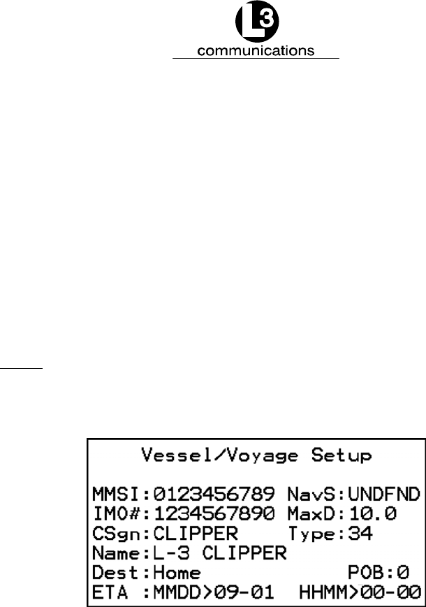
Marine Systems
Aviation Recorders
Initial Issue
Dec. 01/06
165M0014-10
Page 2–14
(3) Enter Data in MMSI Field ( MMSI ).
(4) Enter Data in Navigational Status Field ( NavS ).
(5) Enter Data in IMO Number Field ( IMO# ).
(6) Enter Data in Maximum Sailing Draft Field ( MaxD ).
(7) Enter Data in Radio Callsign Field ( CSgn ).
(8) Enter Data in Vessel Type Field ( Type ). (Refer to Table 2–3.)
(9) Enter Data in Vessel Name Field ( Name ).
NOTE: Destination (Dest), ETA, and POB are optional fields and
can be entered at this time if known.
(10) Press ESC to return to the AIS Main System Menu screen.
Figure 2–7. Vessel Data Setup

Marine Systems
Aviation Recorders
Initial Issue
Dec. 01/06
165M0014-10
Page 2–15
Table 2–3. Vessel Type Codes
Special Crafts Other Ships
First Digit Second Digit
50 Pilot Boats
51 Search and Rescue Vessels
52 Tugs
53 Port Tenders
54 Vessels with anti-pollution
facilities or equipment
55 Law Enforcement Vessel
56 Spare - for assignment to
local vessels
57 Spare - for assignment to
local vessels
58 Medical Transport (as defined
in the 1949 Geneva
Conventions)
59 Spare - Ships according to
RR Resolution No. 18
(Mob-83)
1 reserved for
future use
2 WIG
3 See Below
4 HSC
5 See Special
Crafts
6 Passenger Ships
7 Cargo Ships
8 Tankers
9 Other types of
ships
0 All ships of this type
1 Carrying DG HS or MP
IMO hazard or pollutant
category A
2 Carrying DG HS or MP
IMO hazard or pollutant
category B
3 Carrying DG HS or MP
IMO hazard or pollutant
category C
4 Carrying DG HS or MP
IMO hazard or pollutant
category D
5 Reserved for future use
6 Reserved for future use
7 Reserved for future use
8 Reserved for future use
9 No additional information
First Digit Second Digit
DG: Dangerous Goods
HS: Harmful Substances
MP: Marine Pollutants
3 Vessel
0 Fishing
1 Towing
2 Towing and length of the
tow exceeds 200 m or
breadth exceeds 25 m
3 Engaged in dredging or
underwater operations
4 Engaged in diving
operations
5 Engaged in military
operations
6 Sailing
7 Pleasure craft
8 Reserved for future use
9 Reserved for future use

Marine Systems
Aviation Recorders
Initial Issue
Dec. 01/06
165M0014-10
Page 2–16
2.1.4.5 Channel Management
This page displays all of the relevant information regarding the regions established
either by manual entry, a governing authority’s VTS station broadcasting region infor-
mation, or another Universal AIS broadcasting the data. These regions determine
the authorized operating frequencies for the coverage area. The user can set these
different configurations at the initial setup; however, the L-3 ProTec Transponder will
acquire the data for a new region once it has entered the region.
Edit Chan Mgmt Settings
NE: N 91’00.0 E 181’00.0
SW: N 91’00.0 E 181’00.0
ChA: 2087 Bw0 ChB:2088 Bw0
PLvl:H Md:TxRxAB TZn: Nm
Src:Intrnl MMSI:---------
FNC: ← Prv. → Nxt. FNC Save
Press FNC → NAV button from any menu and use the up (↑) or down (↓) arrow
keys.
NE: Indicates the North East corner of the region.
SW: Indicates the South West corner of the region.
ChA: Channel Frequency for Channel A.
Bw: Bandwidth 0 = 25 kHz, 1 = 12.5 kHz.
ChB: Channel Frequency for Channel B.
Bw: Bandwidth 0 = 25 kHz, 1 = 12.5 kHz.
Plvl: Power Level H = high power (12.5 Watts), L = low power (2 Watts)
Md: TxRxAB, TARxAB, TBRxAB, RxAB, RAOnly, and RBOnly.
TZn: Transition zone size, defined in nautical miles.
Src: Intrnl = Internal command, Extrnl = External command
(governing authority).
MMSI: MMSI of the authority that has issued the command (blank if internal).
For the initial setup perform the following:
(1) Press the FNC key.
(2) Press the NAV key. The AIS Main System Menu screen will appear.
(3) Using the down Arrow key, select “Edit Chan Mgmt Settings”, and press the
ENT key. The Channel Management Table Entry screen will appear. (Refer to
Figure 2–8.)
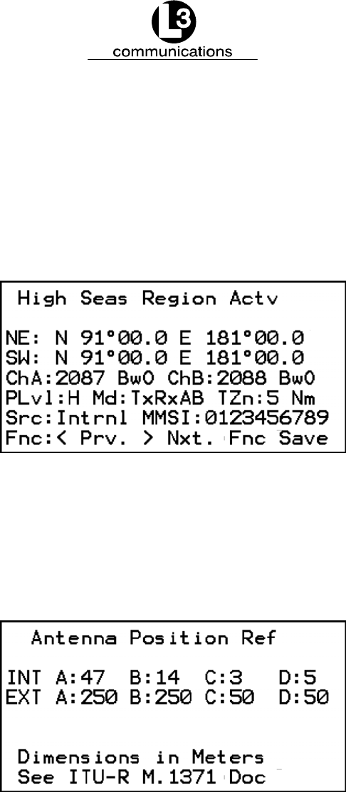
Marine Systems
Aviation Recorders
Initial Issue
Dec. 01/06
165M0014-10
Page 2–17
(4) Use the up and down arrow keys and the left and right arrow keys to highlight
an entry point, and press the ENT key.
(5) Enter the data, press the ENT key, and move to the next data entry point.
(6) After all of the data is entered for that region, press the FNC key twice and then
press the ENT key to save the data.
(7) Press the ESC key to return to the AIS Main System Menu screen.
Figure 2–8. Channel Management Settings Screen
2.1.4.6 Antenna Position
This setup provides for data entry of location of the antenna for each of the GPS an-
tennas required for the system. The ‘Int’ refers to the antenna dedicated to the AIS’
internal GPS and the ‘Ext’ refers to the antenna dedicated to the ship’s external
GPS. The screen layout is as follows:
Figure 2–9. Antenna Position Screen

Marine Systems
Aviation Recorders
Initial Issue
Dec. 01/06
165M0014-10
Page 2–18
To enter the antenna position, perform the following:
(Refer to Figure 2–9 and Figure 2–10)
(1) Press the FNC key.
(2) Press the NAV key. The AIS Main System Menu screen will appear.
(3) Using the down Arrow key, select “Antenna Position Setup”, and press the ENT
key. The Antenna Position Reference screen will appear.
(4) Use the up and down arrow keys and the left and right arrow keys to highlight
an entry point, and press the ENT key.
(5) Enter the data, press the ENT key, and move to the next data entry point.
(6) Press the ESC key to return to the AIS Main System Menu screen.
NOTE: The INT antenna is the antenna dedicated to the GPS re-
ceiver internal to the AIS. The EXT antenna is the antenna
dedicated to the ship’s dGPS. The dimensions are to be
entered in Meters and are defined as follows: (Refer to
Figure 2–10.)
A
B
CD
A Distance in meters from Forward
Perpendicular (FP)
B Distance in meters from After
Perpendicular (AP)
C Distance in meters inboard from
port side
D Distance in meters inboard from
starboard side
Figure 2–10. Antenna Position Measurements

Marine Systems
Aviation Recorders
Initial Issue
Dec. 01/06
165M0014-10
Page 2–19
2.1.4.7 Text Messaging
Text messages include specific addressed messages, broadcast messages, and
safety messages. To send a particular type of message perform the steps as de-
scribed below:
MMSI: Maritime Mobile Service ID: Nine digit unique identification number
Mode: Mode:
Broadcast: 0 = Default
Addressed: Enter MMSI
TXch: Transmit Channel:
Auto Select: Default
ChanA: Send on channel A
ChanB: Send on channel B
Chan A and B: Send on both channels
Text: Safety Message Text to be Sent: Up to 156 alphanumeric characters
To send an addressed message, perform the following:
(1) Press MSG key (From any menu).
(2) Ensure the MMSI is highlighted.
(3) Press the ENT key, and enter the MMSI number of the ship to be addressed,
press the ENT key.
(4) Press the down arrow key to highlight “Mode” and press the ENT key.
(5) Using the down arrow key, highlight “Addressed”, and press the ENT key.
(6) Using the down arrow key, highlight the text portion of the screen, press the
ENT key, and type in the message.
(7) Press the MSG key to broadcast the message.
To broadcast a message, perform the following:
(1) Press MSG key.
(2) Verify that the MMSI number is a zero.
(3) If the MMSI is not a zero, press the down arrow key until the MMSI is high-
lighted.
(4) Press the ENT key, and press the CLR key.
(5) Press the down arrow key to highlight “Mode” and press the ENT key.
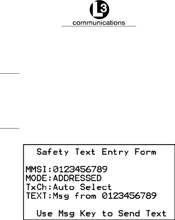
Marine Systems
Aviation Recorders
Initial Issue
Dec. 01/06
165M0014-10
Page 2–20
(6) Using the down arrow key, highlight “Broadcast”, and press the ENT key.
NOTE: Unless instructed, leave TxCh to Auto Select.
(7) Using the down arrow key, highlight the text portion of the screen, press the
ENT key, and type in the message.
(8) Press the MSG key to broadcast the message.
NOTE: “Successful Transmission” should be displayed at the
bottom of the screen.
Figure 2–11. Safety Text Message
2.1.4.8 View Safety Text Log
This log shows any safety text messages that have been received during the pres-
ent power up.
To review Safety Text Messages that have been received,
perform the following:
(1) Press the FNC key.
(2) Press the NAV key. The AIS Main System Menu screen will appear.
(3) Using the down Arrow key, select “View Safety Text Log”, and press the ENT
key. The Safety Text Review screen will appear.
(4) Use the left and right arrows to view previous or next messages respectively.
(5) Press the ESC key to return to the AIS Main System Menu screen.
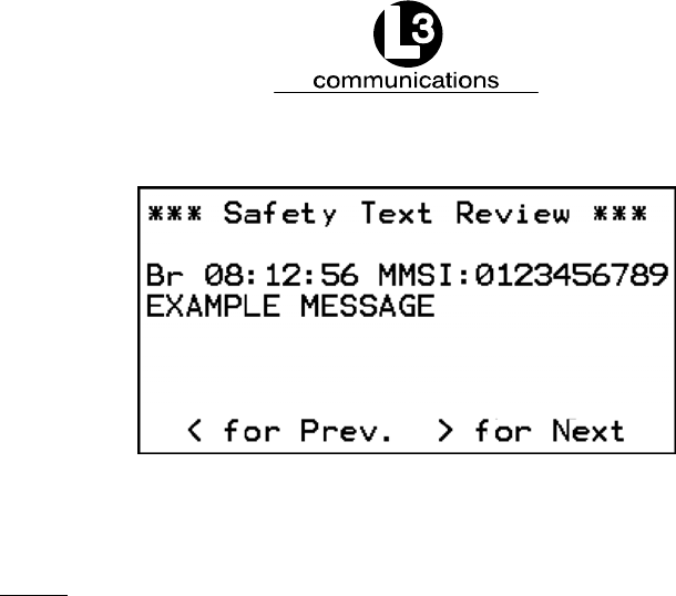
Marine Systems
Aviation Recorders
Initial Issue
Dec. 01/06
165M0014-10
Page 2–21
Figure 2–12. Safety Text Review Screen
2.1.4.9 Change Password
NOTE: Only users with an administrative password can change
passwords
To change the transponder’s access password, perform the following:
(1) Press the FNC key.
(2) Press the NAV key. The AIS Main System Menu screen will appear.
(3) Using the down Arrow key, select Change Password, and press the ENT key.
The System Password Change screen will appear.
(4) Enter the new password, and press the ENT key.
(5) Enter the new password in the Verify field, and press the ENT key. This will
save the new password.
(6) Use the Up (↑) and Down (↓) keys too select type of Access, and press the
ENT key.
PassWd: New password.
Verify: Confirmation of new password
Access: ADMIN = administrator, USER = user.
(7) Press the ESC key to go back to the AIS Main System Menu screen.
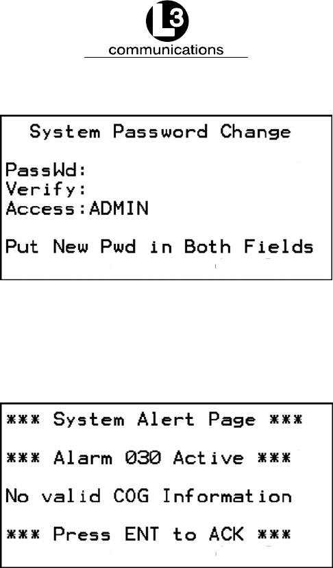
Marine Systems
Aviation Recorders
Initial Issue
Dec. 01/06
165M0014-10
Page 2–22
Figure 2–13. Password Change Screen
2.1.4.10 System Alert Screen
This screen will appear when a system alert is received. Press the ENT key to ac-
knowledge the alert.
Figure 2–14. System Alert Screen
2.1.4.11 Alarm Status
The ProTec AIS unit does not support a “General Failure” alarm since all detected
failures are reported with an explicit discrete alarm message. Refer to Table 2–4 for
an explanation of the alarm codes. Table 2–4 explains the codes that are referenced
on this page.

Marine Systems
Aviation Recorders
Initial Issue
Dec. 01/06
165M0014-10
Page 2–23
To review Safety Text Messages that have been received, perform the
following:
(1) Press the FNC key.
(2) Press the NAV key. The AIS Main System Menu screen will appear.
(3) Using the down Arrow key, select “View Alarm Status”, and press the ENT key.
(4) Use the up (↑) or down (↓) arrow keys to view previous or next messages re-
spectively.
(5) Press the ESC key to return to the AIS Main System Menu screen.
AA: Alarm is active and has been acknowledged.
AV: Alarm is active and has not been acknowledged.
Figure 2–15. Alarm Status Screen

Marine Systems
Aviation Recorders
Initial Issue
Dec. 01/06
165M0014-10
Page 2–24
Table 2–4. Integrity Alarm Conditions Signalled Using ALR Sentence Formatter
Alarm’s description
text
Alarm condition
threshold exceeded
Alarm condition
exceeded
Alarm ID
Text Identifier
Reaction of the system to the alarm
condition threshold exceeded
AIS: Tx malfunction A V 001 Stop transmission
AIS: Antenna VSWR exceeds limit A V 002 Continue operation
AIS: Rx channel 1 malfunction A V 003 Stop transmission on affected channel
AIS: Rx channel 2 malfunction A V 004 Stop transmission on affected channel
AIS: Rx channel 70 malfunction A V 005 Stop transmission on affected channel
AIS: general failure A V 006 Stop transmission
AIS: MKD connection lost A V 008 continue operation with “DTE” set to “1”
AIS: external EPFS lost A V 025 continue operation
AIS: no sensor position in use A V 026 continue operation
AIS: no valid SOG information A V 029 continue operation using default data
AIS: no valid COG information A V 030 continue operation using default data
AIS: Heading lost/invalid A V 032 continue operation using default data
AIS: no valid ROT information A V 035 continue operation using default data
AIS: IEC Com Error A V 051 indicates miswired NMEA port, continue
operation
1
2
2
2
2
1If applicable
2When so configured
As per IEC 61193–2

Marine Systems
Aviation Recorders
Initial Issue
Dec. 01/06
165M0014-10
Page 2–25
2.1.4.12 General Status Screen
This menu page displays a table of events describing the general status of the oper-
ating unit along with a time stamp of when each automatic entry was made.
Table 2–5 explains the codes that are referenced on this page. Refer to Table 2–5
for an explanation of the General Status codes.
To review the ProTec General status, perform the following:
(1) Press the FNC key.
(2) Press the NAV key. The AIS Main System Menu screen will appear.
(3) Using the down Arrow key, select “View General Status”, and press the ENT
key. The General Status screen will appear. (Refer to Figure 2–16.)
(4) Press the ESC key to return to the AIS Main System Menu screen.
Figure 2–16. General Status Screen

Marine Systems
Aviation Recorders
Initial Issue
Dec. 01/06
165M0014-10
Page 2–26
Table 2–5. Sensor Status Indications Signalled Using TXT Sentence Formatter
Text Message
Text Identifier
Reaction of the system
AIS: UTC clock lost 007 Continue operation using indirect or semaphore
synchronization
AIS: external DGNSS in use 021 Continue operation
AIS: external GNSS in use 022 Continue operation
AIS: internal DGNSS in use (beacon) 023 Continue operation
AIS: internal GNSS in use (message 17) 024 Continue operation
AIS: internal GNSS in use 025 Continue operation
AIS: external SOG/COG in use 027 Continue operation
AIS: internal SOG/COG in use 028 Continue operation
AIS: Heading valid 031 Continue operation
AIS: Rate of Turn Indicator in use 033 Continue operation
AIS: Other ROT source in use 034 Continue operation
AIS: Channel management parameters changed 036 Continue operation
As per IEC 61193–2

Marine Systems
Aviation Recorders
Initial Issue
Dec. 01/06
165M0014-10
Page 2–27
2.1.4.13 Down-Time Log
This screen shows the date, time and duration that the transponder has been pow-
ered off.
To review Down-Time Log, perform the following:
(1) Press the FNC key.
(2) Press the NAV key. The AIS Main System Menu screen will appear.
(3) Using the down Arrow key, select “View Down-Time Log”, and press the ENT
key.
(4) Use the down arrow to view the down times that are further down the list.
(5) Press the ESC key to return to the AIS Main System Menu screen.
Figure 2–17. Down-Time Log Screen
2.1.4.14 LCD Viewing Angle Adjustment
This menu page allows the user to adjust the contrast of the LCD display on all
pages and screens.
Use the up (↑) or left (←) arrow keys to decrease the viewing angle.
Use the down (↓) or right (→) arrow keys to increase the viewing angle.
To enter adjust the LCD viewing angle, perform the following:
(1) Press the FNC key, press the NAV key. The AIS Main System Menu screen will
appear.
(2) Using the down Arrow key, select Adj LCD Viewing Angle, and press the ENT
key. The LCD Viewing Angle Adjust screen will appear. (Refer to Figure 2–18.)
(3) Use the Left or Up arrows to decrease the viewing angle, or use the Right or
Down arrows to increase the viewing angle.
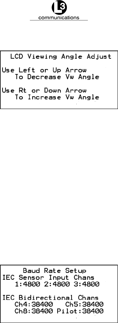
Marine Systems
Aviation Recorders
Initial Issue
Dec. 01/06
165M0014-10
Page 2–28
(4) Press the ESC key to return to the AIS Main System Menu screen.
Figure 2–18. LCD Viewing Angle Adjust Screen
2.1.4.15 Baud Rate Setup
IEC Sensor Input Channels: Valid baud rates for CH1, CH2, and CH3 - 4800,
9600, 19200, and 38400. (Default = 4800)
IEC Bidirectional Channels: Valid baud rates for CH4, CH5, CH8, and Pilot
(front panel) are 4800, 9600, 19200, 38400.
(Default = 38400)
To setup the Baud Rate, perform the following:
(1) Press the FNC key, press the NAV key. The AIS Main System Menu screen will
appear.
(2) Using the down Arrow key, select Set Baud Rate, and press the ENT key. The
Baud Rate Setup screen will appear. (Refer to Figure 2–19.)
(3) Using all of the arrow keys, highlight an entry point, and press the ENT key.
(4) Enter the data, press the ENT key, and move to the next data entry point.
(5) Press the ESC key to return to the AIS Main System Menu screen.
Figure 2–19. Baud Rate Setup Screen

Marine Systems
Aviation Recorders
Initial Issue
Dec. 01/06
165M0014-10
Page 2–29
2.1.4.16 Set AIS Channels
This menu page allows the administrator to set the default, Open Seas, transmit and
receive frequencies as well as the operating power level.
AIS Channel A: 2087 should be default (Channel 87B, 161.975 MHz)
AIS Channel B: 2088 should be default (Channel 88B, 162.025 MHz)
Power Level: Hi = high power, Lo = low power
To enter System Information and Configuration information, perform the fol-
lowing:
(1) Press the FNC key, press the NAV key. The AIS Main System Menu screen will
appear.
(2) Using the down Arrow key, select Set AIS Channels, and press the ENT key.
The AIS Channel Setup screen will appear. (Refer to Figure 2–20.)
(3) Using all of the arrow keys, highlight an entry point, and press the ENT key.
(4) Enter the data, press the ENT key, and move to the next data entry point.
(5) Press the ESC key to return to the AIS Main System Menu screen.
Figure 2–20. AIS Channel Setup Screen

Marine Systems
Aviation Recorders
Initial Issue
Dec. 01/06
165M0014-10
Page 2–30
THIS PAGE IS INTENTIONALLY LEFT BLANK.

Marine Systems
Aviation Recorders
Initial Issue
Dec. 01/06
165M0014-10
Page 3–1
SECTION 3
ProTec
AUTOMATIC IDENTIFICATION SYSTEM (AIS)
INSTALLATION

Marine Systems
Aviation Recorders
Initial Issue
Dec. 01/06
165M0014-10
Page 3–2
THIS PAGE IS INTENTIONALLY LEFT BLANK.
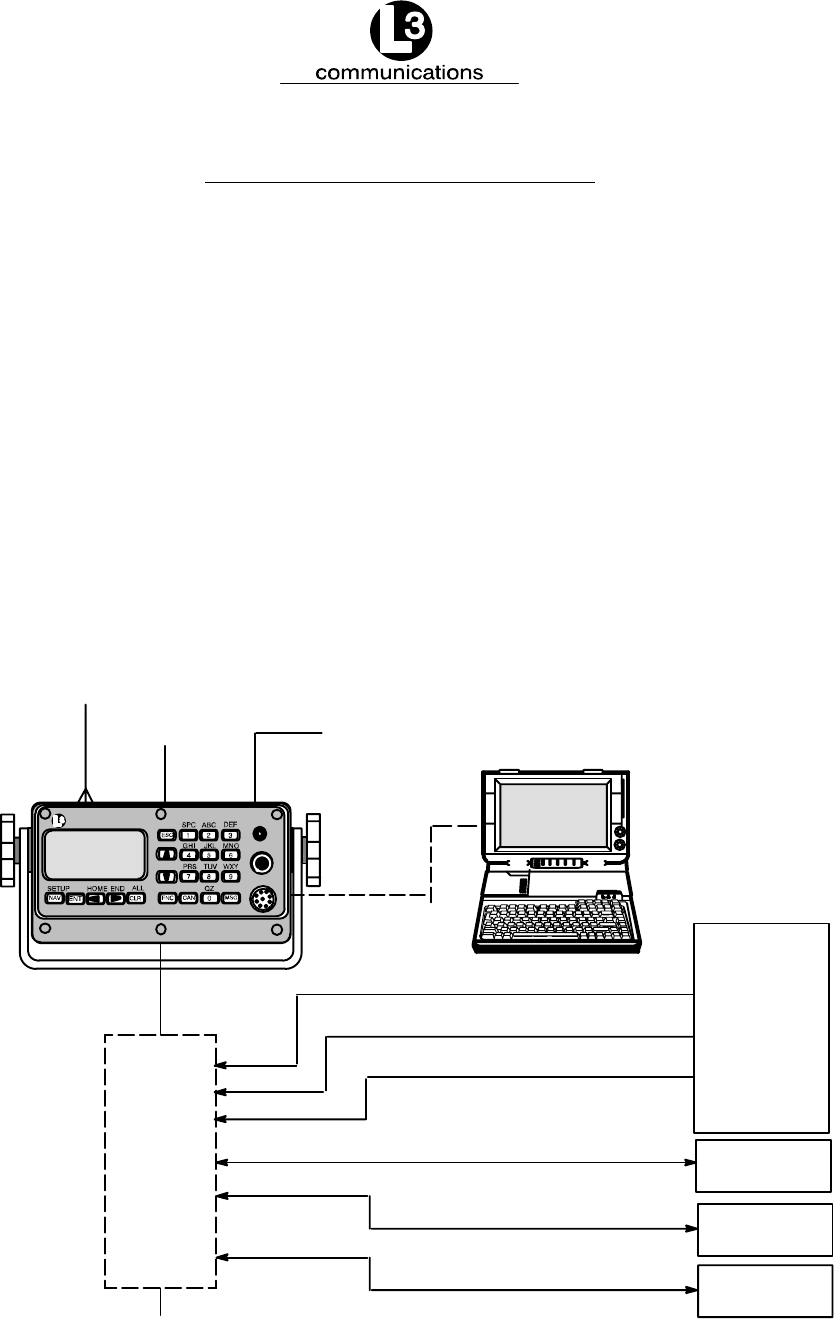
Marine Systems
Aviation Recorders
Initial Issue
Dec. 01/06
165M0014-10
Page 3–3
ProTec AIS Installation
3.1. Installation
The L-3 ProTec Transponder has been designed for easy installation into any exist-
ing bridge layout. Figure 3–1 gives a general representation of the system layout.
Installation can be broken down into 5 distinct operations as follows:
FTransponder
FVHF Antenna
FGPS Antenna
FData Interface
FPowerup and Configuration
Each operation will be discussed in detail below. In regards to 3rd part components
such as VHF and GPS antennas and Gyro interfaces, it is suggested that the
installation procedures suggested by the manufacturer be followed in lieu of these
procedures.
Junction
Box
IEC 61162 HDG, ROT
TRANSPONDER UNIT
IEC 61162 HDG, SOG, COG, ROT, POSN
POSN, SOG, COG
SHIP
SENSORS
(Optional)
RADAR
ECDIS
PILOT/PC
AIS DATA
AIS DATA
AIS DATA
VHF Antenna
150M-W2VN
GPS
24VDC - 10 Amp
Power
PILOT/PC
24 VDC
(Optional)
communications
PILOT
AUTOMATIC IDENTIFICATION SYSTEM
STATUS
ON / OFF / DIM
Figure 3–1. AIS Transponder Interconnection Diagram

Marine Systems
Aviation Recorders
Initial Issue
Dec. 01/06
165M0014-10
Page 3–4
3.1.1. Transponder
The L-3 ProTec is a single box design which is easily installed into any existing
bridge layout. The compact design requires minimal clearance (refer to Section 4
Figure 4–1 and Figure 4–2) and can be mounted in a trunion bracket or mounted
flush using the available flush–mount bracket.
FMount the transponder in a position which provides easy access to the key-
board and display.
FIf using the trunion bracket, the mount itself may be used to mark the screw
holes on the mounting surface. When locating the transponder, consider that
the IMO mandates that the AIS keyboard and display be easily accessed from
a navigable position on the bridge.
FIf used, Mount the transponder in the trunion utilizing the trunion knobs pro-
vided, otherwise mount transponder in flush mount bracket.
FLocate and mount the terminal block or junction box in a position near the
transponder. The IEC cable provided with the unit is 100 inches (2.54 m) long.
Locate the terminal block in a fashion which allows for easy access to the termi-
nals for making the connections to required input/output feeds.
FWhen connecting the power cable, the “Red“ lead goes to positive and “Black“
to negative. Ensure proper ground wire attachment to ships structure. The oth-
er two leads can be used to connect to an external alarm system. This alarm
system can provide an audio and/or visual alarm in the event of an internal sys-
tem malfunction, or if the AIS loses power or is turned off.
Install the transponder, and complete the AIS Installation Checklist found it Ap-
pendix A, as follows:
(1) Mount the transponder. (In trunion, if used.)
NOTE: A junction box may be used in place of the terminal block.
(2) Locate an ideal position for the terminal block.
FProtected from weather.
FProtected from high heat.
FProtected from accidental contact with conductive material.
FWithin 100 inches (2.5 m) of the transponder due to IEC data cable length.
FGrounding of terminal block to ship’s structure.
FNeed to feed cables from navigational sensors.
(3) Mount terminal block or junction box with self tapping screws.
(4) Ground terminal block to ship’s structure using grounding cable provided.

Marine Systems
Aviation Recorders
Initial Issue
Dec. 01/06
165M0014-10
Page 3–5
For steps (5) through (9) refer to Paragraph 3.1.2.
(5) Connect the IEC cable to data port on back of Transponder.
NOTE: If an interface adapter must be used to convert either Gyro
output and/or dGPS output to IEC (NMEA 0183) standard,
the output from the interfaces should be located as near as
possible to the sending unit (Gyro or dGPS) and the output
cables led to the IEC terminal block.
(6) Lead data cables from Gyrocompass data output port to terminal block.
(7) Lead data cables from ship’s DGPS data output port to terminal block.
(8) Feed the IEC data cable to the terminal block.
NOTE: The metallic shielding of each of the three shielded cables
containing the twisted pairs must be connected to the ter-
minal block using the shield drain wire connected to the
shield. The shields from Cables 1 and 2 do not have to be
connected. The shield from Cable 3 must be connected to
TB pin ID 30, which is grounded to the ship’s hull.
(9) Connect each wire in the IEC data cable to the terminal block. (Refer to
Figure 3–3 and Table 3–2.)
(10) Connect power cable to transponder. (Refer to Figure 3–4.)
NOTE: Due to the stringent transmit attack and release times spe-
cified in ITU 1371, a robust power source is required for
proper operation. Recommended current ratings for power
sources are:
24 VDC – 10 Amp
The transponder may operate improperly if the power
source does not have the recommended minimum current
ratings.
(11) Connect power cable to ships 24 Vdc, 10 Amp minimum power supply is rec-
ommended. ( Red + , Black – )
(12) Connect the other two leads to external alarm system if desired.
(13) If an external display system is to be connected, lead the pilot port cable from
the display unit to the terminal block. (Refer to Figure 3–5.)
CAUTION: Do not power up the unit at this time.
(14) Go to Paragraph 3.1.3. for VHF antenna installation steps.

Marine Systems
Aviation Recorders
Initial Issue
Dec. 01/06
165M0014-10
Page 3–6
3.1.2. Connecting the IEC Data Interface Cable
The AIS Transponder receives data from the ship’s sensors through a data interface
cable which is connected to the back of the transponder through a data port. IMO
regulations require that the ship heading, speed–over–ground (SOG), course–over–
ground (COG), rate–of–turn (ROT) and position be transmitted from the AIS. In or-
der to meet these requirements, the L-3 ProTec provides six (6) data channels to al-
low the AIS to be connected to the ships Gyrocompass and DGPS system in accor-
dance with NMEA 0183.
The L3 AIS is shipped with one IEC interface cable P/N 024M0088-01. All IEC/Pilot
communications with the AIS is referenced with the L-3 ProTec considered the
“MASTER” in that transmit data is OUTPUT from the L-3 ProTec, and receive data is
INPUT to the L-3 ProTec. All channels are isolated with individual shielded twisted
pair cables. The IEC connector (J4) is located on the back of the L-3 ProTec. (Refer
to IEC 61993–2 annex D. and NMEA 0183) IEC channels 1, 2, and 3 are RECEIVE
ONLY sensor inputs. Differential data (RS422) is received on each of these chan-
nels and internally converted to TTL for input to a standard UART. Channels 4, 5,
and 8 are all RS422 interfaces. IEC channels 4 and 5 are TRANSMIT/RECEIVE
channels for AIS data. IEC channel 8 is the AIS long range port.
3.1.2.1 Data Channels
Data enters the Transponder through six (6) available data channels. Three data
channels are low speed unidirectional (4800 baud) channels suitable for data input
to the transponder. The other three data channels are high speed bidirectional
channels (38400 baud) which support both input and output to/from the transponder.
The channels are described below by channel number and type. Suggested uses of
each channel are provided but it is not required that a user define the channels in
this fashion. The internal software in the transponder is able to distinguish the type
of data feeding from each channel provided all data streams subscribe to the IEC
61162 format (NMEA 0183).
Table 3–1. Data Channels
Channel BAUD Type Suggested Use
1 4800 Receive dGPS (COG, SOG, LAT, LON)
2 4800 Receive Rate of Turn
3 4800 Receive Heading (Gyro)
4 38400 Transmit / Receive PC Application
5 38400 Transmit / Receive ARPA/ECDIS
8 38400 Transmit / Receive Long Range Tracking (Dedicated)

Marine Systems
Aviation Recorders
Initial Issue
Dec. 01/06
165M0014-10
Page 3–7
The IEC I/O electrical characteristics are as follows:
The “A”, “B” and “C” leads are as defined in IEC 61162–1, 61162–2 and V.11.
“A” and “B” are both signal leads with “C” being the effective return for both the “A”
and “B” leads.
“A” and “B” operate differentially to each other.
High–level output voltage is 4V minimum from the “A” lead to the “C” lead and from
the “B” lead to the “C” lead. Low–level output voltage is 0.4V maximum.
Recommended maximum output current capability is 110mA.
Input is differential from “A” to “B”. Effective input resistance is 4.9k ohm across “A”
and “B” and 96k from “A” or “B” to “C”.
Differential input voltage threshold is 250mV maximum.
Inputs will meet the requirement of withstanding +/–15V between any two leads, “A”,
“B” or “C”.
3.1.2.2 Data Cable
Each transponder will come shipped with an 100 inches long IEC data cable (P/N
024M0088-01) terminated at one end by a J4 connector. (Refer to Figure 3–2 and
Figure 3–3.) The IEC data cable is shielded and contains three smaller diameter
cables, each of which is also shielded. Each of these smaller cables contains three
shielded twisted pairs (STP) each and each STP includes a drain wire. A low speed
unidirectional (input only) data channel (4800 Kbs) is carried through one STP, and a
high speed bidirectional (input/output) data channel (38400 Kbs) will require two
pairs.
3.1.2.3 Terminal Block
A terminal block is the preferred installation method for completing the data interface
(NMEA) because data output from a ship sensor ( dGPS, ROT, Gyro) may not sub-
scribe to a standard pinout definition. As such, each installation may require that
the installer identify and cross reference the sensor pinouts with the IEC pinouts,
which is a well defined standard pinout description. The terminal block allows for
greater flexibility in completing the connection to the ship’s sensors.
A junction box may be made available which terminates the data cable on the termi-
nal block and provides serial connectors to allow for easy connection to ship sen-
sors. However, the installer will need to confirm the pinout definitions for the sensor
outputs before completing the connection correctly.
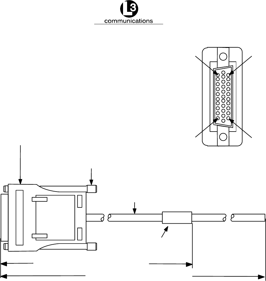
Marine Systems
Aviation Recorders
Initial Issue
Dec. 01/06
165M0014-10
Page 3–8
P1–Connector, Cannon p/n 2DA31P
Metal or metalized plastic backshell,
Cannon p/n DA121073–150 or Equivalent
Thumbscrew, Cannon p/n 250–8501–013
or Equivalent
Cable, ECS p/n 622818
Marker, Brady p/n PWC–PK3
or Equivalent
Pin 1
Pin 10
Pin 31
Pin 22
100 in. 12 in. 25.4 cm 3 cm
10 in. 2 in. 2.54 cm 0.5 cm
Figure 3–2. AIS Transponder IEC Data Cable

Marine Systems
Aviation Recorders
Initial Issue
Dec. 01/06
165M0014-10
Page 3–9
12–24 VDC
BLACK (–)
RED (+)
GREEN (BIIT 1)
WHITE (BIIT 2)
GPS
ANT
VHF
ANT
PL 259
CONN.
TNC
CONN.
RG213/RG214 COAX.
CABLE GROUP 1
1
11
22
2
12
23
3
13
24
NC
4
14
25
5
15
26
6
16
27
NC
8
19
29
9
20
30
10
21
31
18
WHITE/BLUE
BLUE/WHITE
SHIELD
WHITE/ORANGE
ORANGE/WHITE
SHIELD
WHITE/GREEN
GREEN/WHITE
SHIELD
CABLE SHIELD
[NO CONNECT]
WHITE/BROWN
BROWN/WHITE
SHIELD
WHITE/GREY
GREY/WHITE
SHIELD
RED/BLUE
BLUE/RED
SHIELD
CABLE SHIELD
[NO CONNECT]
RED/ORANGE
ORANGE/RED
SHIELD
RED/GREEN
GREEN/RED
SHIELD
RED/BROWN
BROWN/RED
SHIELD
CABLE SHIELD
1
2
3
10
11
12
4
5
6
10
7
8
9
17
18
19
24
25
26
20
13
14
15
20
21
22
27
28
29
30
31
CABLE GROUP 2 CABLE GROUP 3
IEC DATA CABLE
(31 PIN)
RATE OF TURN
NMEA 0183
RS 422 CH 2
HEADING
NMEA 0183
RS 422 CH 3
PC/EXT APP.
NMEA 0183
RS 422 CH 4
TX
TX
B
A
B
A
POSITION
NMEA 0183
RS 422 CH 1
TX
B
A
B
A
A
B
TX
B
A
B
A
TX
RX
ECDIS/ARPA
NMEA 0183
RS 422 CH 5
B
A
RX
B
A
TX
LONG RANGE
NMEA 0183
RS 422 CH 8
RX
Open = Pass
Short = Fail
Note: Alarm Relay Output
RG213/RG214 COAX.
JUNCTION BOX
TERMINAL BLOCK
Figure 3–3. IEC Data Cable External Wiring Diagram

Marine Systems
Aviation Recorders
Initial Issue
Dec. 01/06
165M0014-10
Page 3–10
NOTE: Each shielded twisted pair of wires is shielded as well by
metallic shielding and a drain wire connected to this shield-
ing is to be connected in accordance with Table 3–2.
Table 3–2. IEC Cable Pinouts
Cable STP Wire Color IEC Pin TB Pin
1White / Blue 1 1
Blue / White 11 2
Shield 22 3
Cable
2White / Orange 2 10
Cable
Group1 Orange / White 12 11
p
Shield 23 12
3White / Green 3 4
Green / White 13 5
Shield 24 6
Shield Drain NC 16
4White / Brown 4 7
Brown / White 14 8
Shield 25 9
Cable
5White / Gray 5 17
Cable
Group 2 Gray / White 15 18
p
Shield 26 19
6Red / Blue 6 24
Blue / Red 16 25
Shield 27 26
Shield Drain NC 23
7Red / Orange 8 13
Orange / Red 19 14
Shield 29 15
Cable
8Red / Green 9 20
Cable
Group 3 Green / Red 20 21
p
Shield 30 22
9Red / Brown 10 27
Brown / Red 21 28
Shield 31 29
Shield 18 30
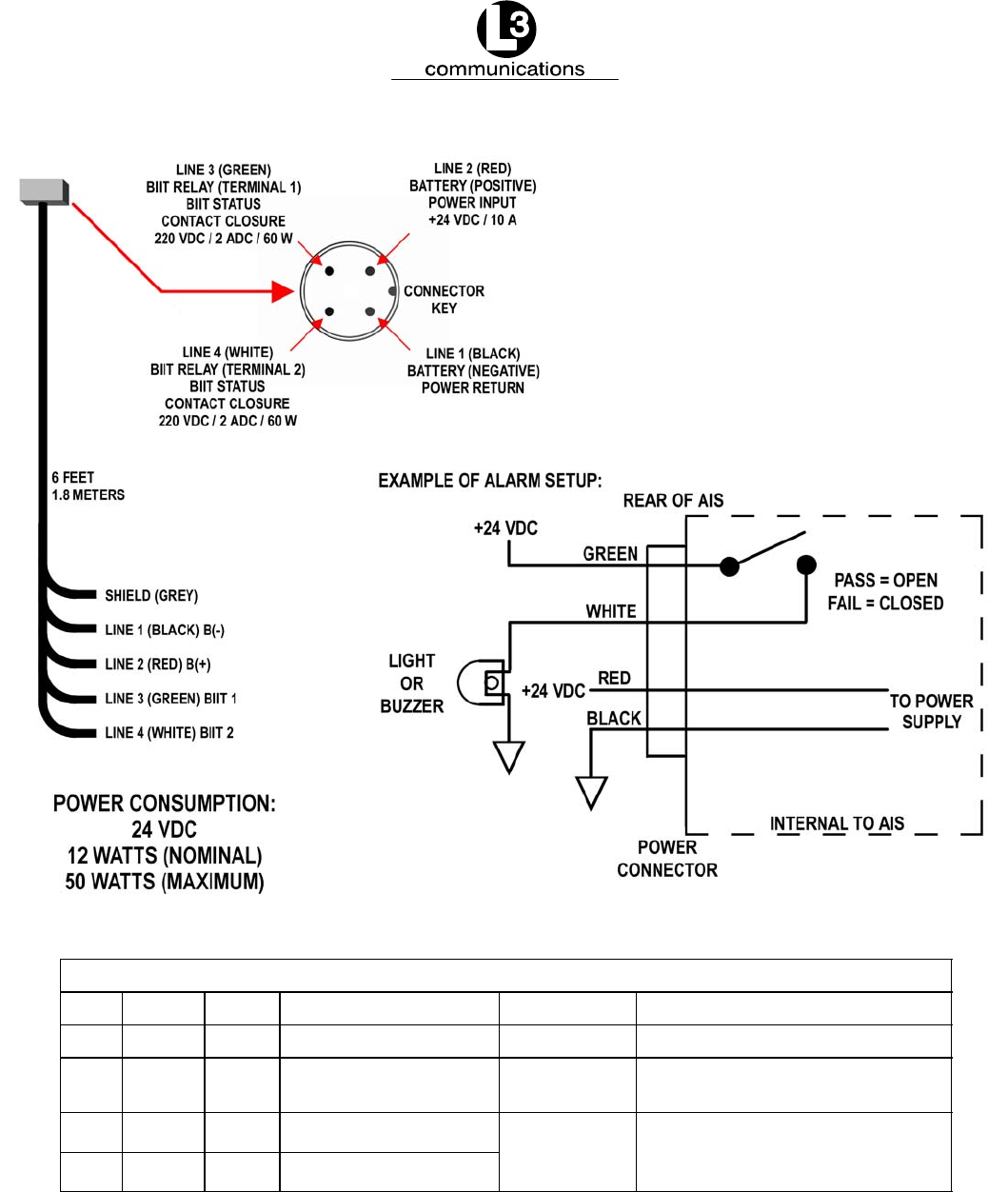
Marine Systems
Aviation Recorders
Initial Issue
Dec. 01/06
165M0014-10
Page 3–11
Signal Table for “Cable Assembly, Power/BIIT, External”
Line Color Name Description Function Power
1 Black B(–) Battery, negative Power return ––
2 Red B(+) Battery, positive Power input +24VDC/10A
(nominal voltages)
3 Green BIIT 1 BIIT relay, terminal 1 BIIT Status Contact closure
220VDC/ 2ADC/ 60W
4 White BIIT 2 BIIT relay, terminal 2
220VDC/ 2ADC/ 60W
maximum
Figure 3–4. AIS Transponder Power Cable
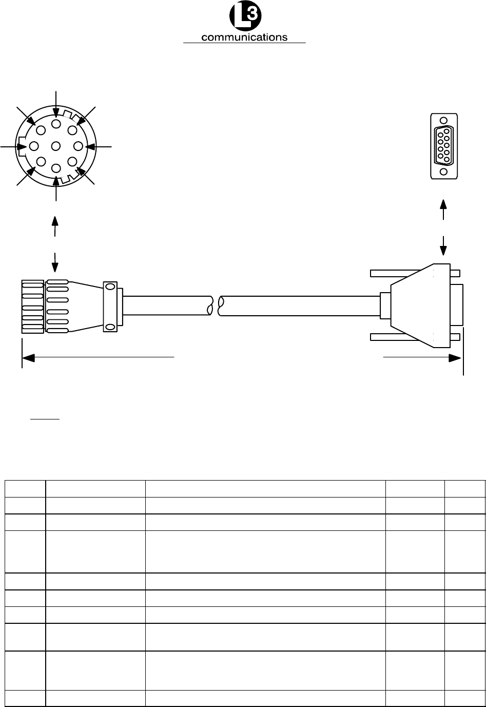
Marine Systems
Aviation Recorders
Initial Issue
Dec. 01/06
165M0014-10
Page 3–12
6
4
91
3
7
8
2
J1 Pilot Port Connector
72 in. 2 1.8 m 0.05 m
5
P2 DB9 Connector
Figure 3–5. Pilot Port Cable
NOTE: A Digital Volt Meter may be used to determine the “A” and “B” polarities. A
negative voltage when referenced to ground would indicate “A”, while a positive
voltage when referenced to ground would indicate “B”.
Table 3–3. Pilot Port Pinout
J1 Pin Name Description Pair Color P2 Pin
1 PILOT_TXA RS4–22 Compliant Output A Blue 2
2 GND Signal/Power 0 Volt Reference Black 5
3+ 8V + 8.0 Volt ( 5%) Output Used to Power External
Test Equipment. External Equipment should be
Current Limited to 300mA
4 PILOT_TXB RS–422 Compliant Output B Black 7
5 PILOT_RXA RS–422 Compliant Input A Green 8
6 PILOT_RXB RS–422 Compliant Input B Black 3
7 TRACE/BOOT_TX TTL–Level RS–232 Serial Output (Trace Message/
Bootload Output)
8 RX_SINAD TDMA / DSC FM Discriminator Output used to
Test Receiver Performance during Special Test
Modes.
9NO CONNECT Not Used

Marine Systems
Aviation Recorders
Initial Issue
Dec. 01/06
165M0014-10
Page 3–13
3.1.3. Installing the VHF Antenna
Installation of a VHF antenna is as important to reliable communications as the
transceiver itself. It is recommended that a high quality antenna be purchased from
an established source and that all manufactures instructions be followed with partic-
ular attention to cable routing and connector installation. Some important consider-
ations in antenna installation are:
FIn general, antennas should be located as high as practical on the vessel
and separated as much as possible from each other.
FThe VHF antenna should be placed in an elevated position with a mini-
mum of 2 meters clearance from any construction that is made with con-
ductive material. In addition, it should not be installed close to any large
vertical obstruction, and the VHF antenna should have a 360° line of sight
to the horizon.
FIt is preferable that the VHF antenna is installed at least 3 meters away
from high power energy sources such as radar and other transmitting ra-
dio antennas, and out of the transmitting beam.
FThere should not be more than one antenna on the same level. The AIS
VHF antenna should be mounted directly above or below the ship’s prima-
ry VHF radiotelephone antenna, with no separation and with a minimum of
2 meters vertical separation. If the VHF antenna is located on the same
level as other antennas, the distance between them should be at least 10
meters.
To install the VHF antenna, perform the following:
(Refer to Figure 3–6 and Figure 3–7.)
(1) Position the antenna mounting bracket on a rigid and structurally sound sur-
face.
(2) Install the antenna on the antenna mount.
NOTE: Use only high quality RG213/RG214 coaxial cable and keep
cable length as short as possible to reduce signal attenua-
tion.
(3) Run the coaxial cable from the antenna to the transponder location.
(4) Trim cable to length leaving a few inches slack at the transponder.
(5) Attach the connectors to the end of the coaxial cable.
(6) Connect the cables to the transponder. Soldering the connection is
recommended.

Marine Systems
Aviation Recorders
Initial Issue
Dec. 01/06
165M0014-10
Page 3–14
3.1.4. Installing the GPS Antenna
The correct installation of a GPS antenna is crucial to the operation of the trans-
ponder because the internal transmission synchronization relies on the accuracy of
the time signal obtained from the GPS. It is recommended that a high quality GPS
antenna be purchased from an established source and that all manufactures instruc-
tions be followed with particular attention to cable routing and connector installation.
Some important considerations in GPS antenna installation are:
FGPS antennas should be located to provide a clear, unobstructed view of
the sky.
FGPS signals can be affected by RADAR and SATCOM transmissions. As
such, GPS antennas should be positioned below and at least 5 meters
away from RADAR and SATCOM antennas and outside of the beam path.
FGPS signals can also be affected negatively by VHF and HF transmis-
sions, and the GPS antenna should be positioned at least 3 meters from
these types of antennas.
FThe GPS antennas can be flat mounted onto any surface but it is recom-
mended that it be elevated from the deck surface (20–30 cm.) to prevent
ice or spray from negatively impacting the signal reception.
FRecently, it has been identified that certain makes/models of TV antennas
can drastically interfere with GPS reception. As such, the installer should
place the GPS antenna as far away from any shipboard TV antennas as
possible and confirm that any antennas used on board are not ones which
have been exhibited GPS interference problems.
To install the GPS antenna, perform the following:
(Refer to Figure 3–6 and Figure 3–7.)
(1) Position the antenna mounting bracket and/or antenna mast on a rigid and
structurally sound surface.
(2) Install the antenna on the antenna mount.
NOTE: Use only high quality RG213/RG214 coaxial cable and keep cable
length as short as possible to reduce signal attenuation.
(3) Run the coaxial cable from the antenna to the transponder location through an
existing throughhull.
(4) Trim cable to length leaving a few inches slack at the transponder.
(5) Attach the connectors to the end of the coaxial cable.
(6) Connect the cable to the transponder. Soldering the connection is
recommended.
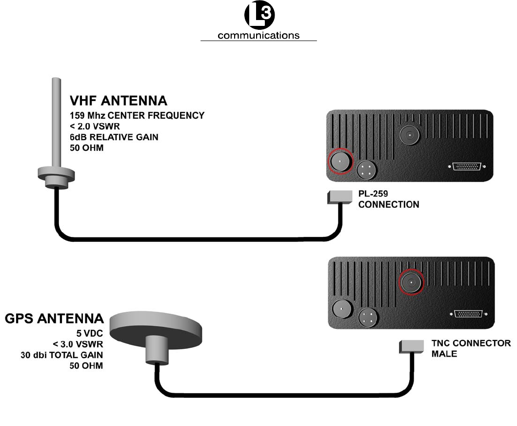
Marine Systems
Aviation Recorders
Initial Issue
Dec. 01/06
165M0014-10
Page 3–15
RG213/RG214
COAXIAL
CABLE
100 FEET
30 METERS
RG213/RG214
COAXIAL
CABLE
30 FEET
9 METERS
Figure 3–6. AIS Transponder Antenna Diagram
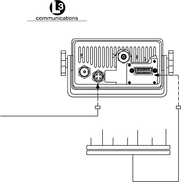
Marine Systems
Aviation Recorders
Initial Issue
Dec. 01/06
165M0014-10
Page 3–16
Back Panel Mating Connectors
VHF Antenna – L3 PN: PL–259 (Generic) (20 ft. cable supplied)
TELEGARTNER J01041A0004
Power BIIT – L3 PN: 063–98–02108 (6 ft. cable supplied)
CONXALL PN: 6382–4SG–522
GPS – L3 PN: TNC (Generic) (20 ft. cable supplied)
IEC NMEA – L3 PN: 063–98–02106 (100 in. cable supplied)
HIROSE PN: HR22–12TPD–20S
Power Consumption: 24 VDC
12 Watts nominal – 50 Watts max.
OTHER
PILOT/PC
ECS
ARPAROT
COG
DGPS
TERMINAL BLOCK
IEC/NMEA DATA
NOTES:
Figure 3–7. AIS Transponder Rear View
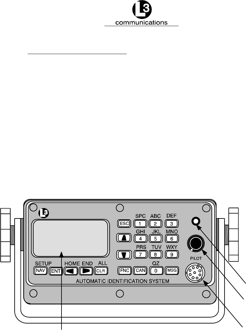
Marine Systems
Aviation Recorders
Initial Issue
Dec. 01/06
165M0014-10
Page 3–17
3.1.5. PowerUp and Configuration
At this stage you should have the following steps completed:
FTransponder installed and 10–28 Vdc power connected.
FVHF antenna installed and connected to transponder.
FGPS antenna installed and connected to transponder.
FIEC data cable installed and connected to transponder and terminal block.
The next step in the installation of the AIS transponder involves setup and configura-
tion. A complete description of the interface and menu system is previously given in
Section 2. Figure 3–8 presents a view of the layout of the integral Minimum Key-
board Display. This display includes a backlit LCD screen and keypad which allows
the user to enter the required static and voyage related vessel data. A complete de-
scription of the user interface and menu system is presented in Section 2. The con-
figuration process is summarized below.
communications
Power/Dim
Status Light
Pilot Port
Display Window
STATUS
ON / OFF / DIM
Figure 3–8. AIS Transponder MKD
3.1.5.1 PowerUp the Transponder
The following procedure should be followed to carry out final setup and testing of the
AIS Transponder.
(1) Rotate the POWER button clockwise to turn on the transponder.
(2) Check the STATUS light for a steady light to ensure power is supplied to unit.

Marine Systems
Aviation Recorders
Initial Issue
Dec. 01/06
165M0014-10
Page 3–18
Table 3–4. ProTec AIS Default Passwords
Default Passwords
Administrative L3AIS
User L3USR
(3) Press FNC and then the NAV button.
(4) Enter Password. Press ENT.
(5) Verify password entry confirmation message is present.
(6) Press ESC to continue.
3.1.5.2 Vessel / Voyage Setup
The Vessel Data Setup screen allows the user to enter the following information
which is required to be completed during the installation of the AIS.
MMSI: Maritime Mobile Service ID: Maximum nine (9) numbers.
NavS: Navigational Status:
UNDFND Undefined
UW–ENG Underway Using Engine
AANCHR At Anchor
NOCMD Not Under Command
RMANUV Restricted Maneuverability
CBDRFT Constrained by Draught
MOORED Moored
AGRND Aground
FISHNG Engaged in Fishing
SAILNG Underway sailing
IMO#: IMO Number: Official IMO designation ID for Vessel. 0 = default =
not available.
MaxD: Maximum Draft: Maximum draft in meters from 0.1 to 25.5 meters.
CSgn: Radio Call Sign: Maximum seven (7) characters.
Type: Vessel Type: (Refer to Table 3–5.)
Name: Vessel Name: Any alphanumeric characters up to 20 in length.
Dest: Destination. The current destination of this voyage.
POB: People on Board. The number of persons currently on board the
vessel.
ETA: Estimated Time of Arrival.
NOTE: Destination, ETA, and POB are optional fields.
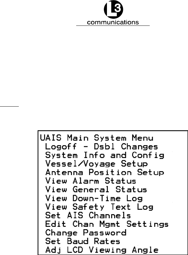
Marine Systems
Aviation Recorders
Initial Issue
Dec. 01/06
165M0014-10
Page 3–19
Perform the following to setup the Vessel/Voyage data:
(1) If already on the UAIS Main System Menu screen, go to Step (2).
Otherwise, press FNC and then NAV to get to the UAIS Main System Menu
screen. (Refer to Figure 3–9.)
NOTE: Figure 3–9 shows the UAIS Main System Menu screen as it
appears as the user initially enters this menu. Not shown is
the Logon option.
Figure 3–9. UAIS Main System Menu
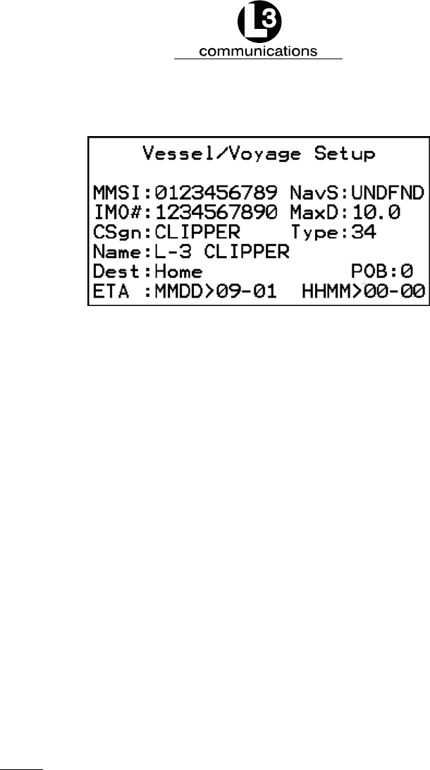
Marine Systems
Aviation Recorders
Initial Issue
Dec. 01/06
165M0014-10
Page 3–20
(2) Use DOWN ARROW key to scroll down to Vessel/Voyage Setup. Press ENT.
Figure 3–10. Vessel/Voyage Setup
Use the following instructions to enter data for Steps (3) through (9). (Refer to
Figure 3–10.)
FUse the LEFT, RIGHT, UP, DOWN arrows to navigate between fields.
FUse the ENT key to select a field to enter.
FUse the alphanumeric keypad to enter the required data into the field.
FUse ENT to save the data entered into the field.
(3) Enter Data in MMSI Field ( MMSI ).
(4) Enter Data in Navigational Status Field ( NavS ).
(5) Enter Data in IMO Number Field ( IMO# ).
(6) Enter Data in Maximum Sailing Draft Field ( MaxD ).
(7) Enter Data in Radio Callsign Field ( CSgn ).
(8) Enter Data in Vessel Type Field ( Type ). (Refer to Table 3–5.)
(9) Enter Data in Vessel Name Field ( Name ).
NOTE: Destination (Dest), ETA, and POB are optional fields and
can be entered at this time if known.
(10) Press ESC to return to the UAIS Main System Menu screen.

Marine Systems
Aviation Recorders
Initial Issue
Dec. 01/06
165M0014-10
Page 3–21
Table 3–5. Vessel Type Codes
Special Crafts Other Ships
First Digit Second Digit
50 Pilot Boats
51 Search and Rescue Vessels
52 Tugs
53 Port Tenders
54 Vessels with anti–pollution
facilities or equipment
55 Law Enforcement Vessel
56 Spare – for assignment to
local vessels
57 Spare – for assignment to
local vessels
58 Medical Transport (as defined
in the 1949 Geneva
Conventions)
59 Spare – Ships according to
RR Resolution No. 18
(Mob–83)
1 reserved for
future use
2 WIG
3 See Below
4 HSC
5 See Special
Crafts
6 Passenger Ships
7 Cargo Ships
8 Tankers
9 Other types of
ships
0 All ships of this type
1 Carrying DG HS or MP
IMO hazard or pollutant
category A
2 Carrying DG HS or MP
IMO hazard or pollutant
category B
3 Carrying DG HS or MP
IMO hazard or pollutant
category C
4 Carrying DG HS or MP
IMO hazard or pollutant
category D
5 Reserved for future use
6 Reserved for future use
7 Reserved for future use
8 Reserved for future use
9 No additional information
First Digit Second Digit
DG: Dangerous Goods
HS: Harmful Substances
MP: Marine Pollutants
3 Vessel
0 Fishing
1 Towing
2 Towing and length of the
tow exceeds 200 m or
breadth exceeds 25 m
3 Engaged in dredging or
underwater operations
4 Engaged in diving
operations
5 Engaged in military
operations
6 Sailing
7 Pleasure craft
8 Reserved for future use
9 Reserved for future use
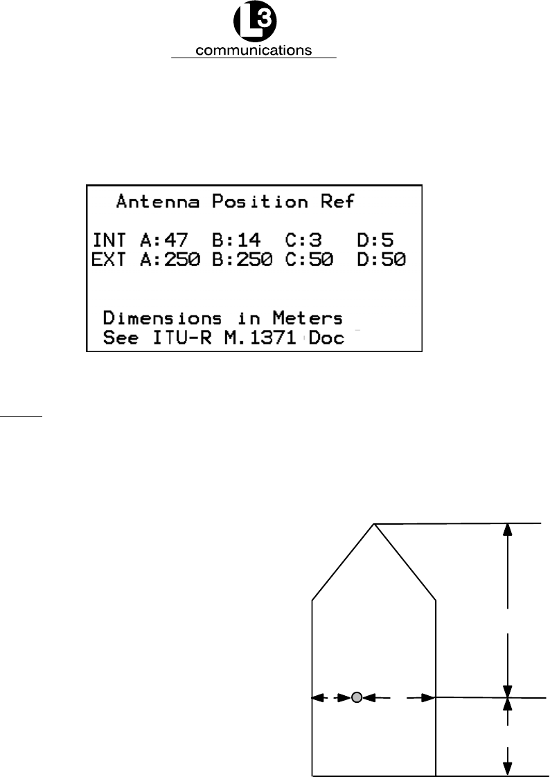
Marine Systems
Aviation Recorders
Initial Issue
Dec. 01/06
165M0014-10
Page 3–22
3.1.5.3 Antenna Position Configuration
(1) On the UAIS Main System Menu screen, use DOWN ARROW key to scroll
down to Antenna Position. Press ENT to select. (Refer to Figure 3–11.)
Figure 3–11. Antenna Position
NOTE: The INT antenna is the antenna dedicated to the GPS re-
ceiver internal to the AIS. The EXT antenna is the antenna
dedicated to the ship’s dGPS. The dimensions are to be
entered in Meters and are defined as follows: (Refer to
Figure 3–12.)
A
B
CD
A Distance in meters from Forward
Perpendicular (FP)
B Distance in meters from After
Perpendicular (AP)
C Distance in meters inboard from
port side
D Distance in meters inboard from
starboard side
Figure 3–12. Calculating Antenna Position
(2) Enter AIS Internal GPS Position. (Refer to Figure 3–12.)
FEnter AIS Internal GPS “A” Position
FEnter AIS Internal GPS “B” Position
FEnter AIS Internal GPS “C” Position
FEnter AIS Internal GPS “D” Position

Marine Systems
Aviation Recorders
Initial Issue
Dec. 01/06
165M0014-10
Page 3–23
(3) Press ENT to save data.
(4) Enter External GPS Antenna Position. (Refer to Figure 3–12.)
FEnter External GPS Antenna “A” Position
FEnter External GPS Antenna “B” Position
FEnter External GPS Antenna “C” Position
FEnter External GPS Antenna “D” Position
(5) Press ENT to save data.
(6) Press ESC to return to the UAIS Main System Menu screen.
(7) Press ESC again to return to the Navigational Display Screen.
3.1.5.4 Verify Transponder Linkup to Ship’s dGPS & GYRO
(1) Press NAV to go to the Own Ship Information Screen.
(2) Confirm ship positional data, heading and SOG/COG/ROT data is correct by
referencing the equipment repeater display.
(3) Confirm that there are no alarms after one minute.
(4) Press ESC to return to the Navigational Display Screen.
The AIS is now placed in service. It is to remain operational at all times when the
vessel is operating unless given specific authorization to discontinue operation by
local maritime authorities. The only interaction with the interface will be to view sur-
rounding ship traffic identification information and to enter voyage specific data at
the start of each voyage.

Marine Systems
Aviation Recorders
Initial Issue
Dec. 01/06
165M0014-10
Page 3–24
THIS PAGE IS INTENTIONALLY LEFT BLANK.

Marine Systems
Aviation Recorders
Initial Issue
Dec. 01/06
165M0014-10
Page 4–1
SECTION 4
ProTec
AUTOMATIC IDENTIFICATION SYSTEM (AIS)
DRAWINGS

Marine Systems
Aviation Recorders
Initial Issue
Dec. 01/06
165M0014-10
Page 4–2
THIS PAGE IS INTENTIONALLY LEFT BLANK.
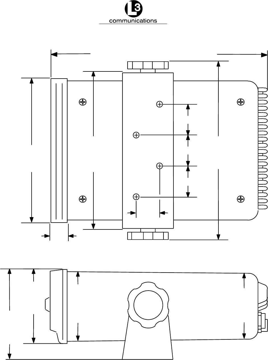
Marine Systems
Aviation Recorders
Initial Issue
Dec. 01/06
165M0014-10
Page 4–3
7.23 in. .12
0.625
in.
1.25 in.
1.25 in.
1.25 in.
0.88 in.
7.81 in. .12
6.87 in. .12
6.40 in. .06
3.28 in.
.06
3.73 in.
.12
3.14 in.
.06 2.937 in.
.06
80 mm
1.5 75 mm
1.5
83 mm
1.5
95 mm
3
174 mm
3
163 mm
1.5
22 mm
31.75 mm
31.75 mm
31.75 mm
198 mm
3
184 mm 3
16 mm
Figure 4–1. AIS Transponder O&D Drawing with Trunion Bracket
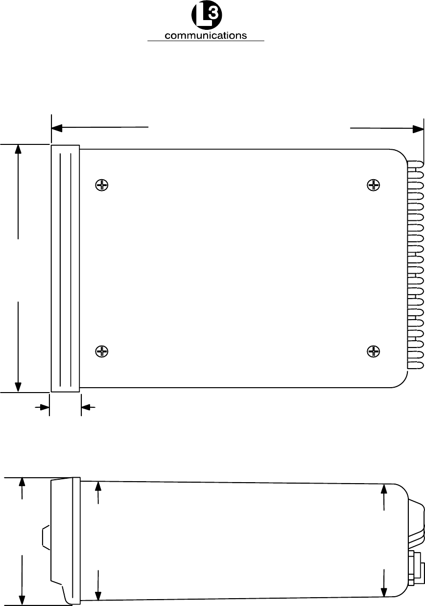
Marine Systems
Aviation Recorders
Initial Issue
Dec. 01/06
165M0014-10
Page 4–4
7.23 in. .12
0.625
in.
6.40 .06
184 mm 3
163 mm
1.5
15.875 mm
3.28 in.
.06
3.14 in.
.06 2.937 in.
.06
80 mm
1.5 75 mm
1.5
83 mm
1.5
Figure 4–2. AIS Transponder O&D Drawing
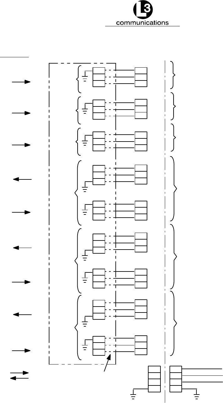
Marine Systems
Aviation Recorders
Initial Issue
Dec. 01/06
165M0014-10
Page 4–5
22
1
11
DB31
CHANNEL 1
CHANNEL 2
CHANNEL 3
CHANNEL 4
CHANNEL 5
CHANNEL 8
7
17
28
18
TEST_V+
TEST_OUT
TEST_GND
NOTES:
DATA DIRECTION IS ASSUMED WITH
THE L3 COMMUNICATIONS UAIS
REFERENCED AS THE MASTER. FOR
EXAMPLE, TRANSMIT DATA
ORIGINATES FROM THE L-3 UAIS AND
RECEIVE DATA IS TERMINATED AT
THE L3 UAIS.
7
17
28
18
N/C
N/C
N/C
24
3
13
25
4
14
23
2
12
8
19
29
26
5
15
9
20
30
27
6
16
10
21
31
P4
RX_A
RX_B
RX_A
RX_B
RX_A
RX_B
TX_A
TX_B
RX_A
RX_B
TX_A
TX_B
RX_A
RX_B
TX_A
TX_B
RX_A
RX_B
5
3
8
5
3
8
5
3
8
5
3
8
7
2
1
5
3
8
5
3
8
7
2
1
7
2
1
DB9 MALE
DB9 MALE
DB9 MALE
DB9 MALE
DB9 MALE
DB9 MALE
IEC CABLE OPTIONAL TERMINATION
PIGTAILS
DATA DIRECTION
CAUTION... PINOUTS
MAY VARY WITH MANUFACTURER.
RS422 TX_A AND TX_B
RS422 RX_A AND RX_B
RS422 RX_A AND RX_B
RS422 RX_A AND RX_B
RS422 TX_A AND TX_B
RS422 TX_A AND TX_B
RS422 TX_A AND TX_B
RS422 TX_A AND TX_B
RS422 TX_A AND TX_B
RS232
Figure 4–3. IEC Data Cable Interconnect Diagram

Marine Systems
Aviation Recorders
Initial Issue
Dec. 01/06
165M0014-10
Page 4–6
THIS PAGE IS INTENTIONALLY LEFT BLANK.

Marine Systems
Aviation Recorders
Initial Issue
Dec. 01/06
165M0014-10
Page A–1
APPENDIX A
ProTec
AUTOMATIC IDENTIFICATION SYSTEM (AIS)
INSTALLATION CHECKLIST

Marine Systems
Aviation Recorders
Initial Issue
Dec. 01/06
165M0014-10
Page A–2
THIS PAGE IS INTENTIONALLY LEFT BLANK.

Marine Systems
Aviation Recorders
Initial Issue
Dec. 01/06
165M0014-10
Page A–3
ProTec AIS INSTALLATION CHECKLIST
Installation Tasks Completed
(Yes / No)
Date
1. Transponder Installed
2. IEC Cable Connected
3. VHF Antenna Installed and Connected
4. GPS Antenna Installed and Connected
Power Up and Configuration Tasks
1. Transponder Powered Up
2. MMSI Number Entered
3. Navigational Status Entered
4. IMO Number Entered
5. Maximum Sailing Draft Entered
6. Radio Callsign Entered
7. Vessel Type Entered
8. Vessel Name Entered
9. Destination Entered (Optional)
10. POB Entered (Optional)
11. ETA Entered (Optional)
Antenna Configuration Tasks
1. AIS Internal GPS Position Entered
2. External GPS Antenna Position Entered
3. Transponder Linkup to Ship’s dGPS & GYRO Verified
4. No Alarms Verified

Marine Systems
Aviation Recorders
Initial Issue
Dec. 01/06
165M0014-10
Page A–4
THIS PAGE IS INTENTIONALLY LEFT BLANK.