LB Technology 96223W-CP IP VIDEO DOOR PHONE User Manual
LB Technology Co., Ltd. IP VIDEO DOOR PHONE Users Manual
UserManual.wiki
>
LB Technology
>
96223W CP User Manual
Users Manual
Navigation menu
Upload a User Manual
Namespaces
Wiki Guide
HTML
PDF
Info
Views
User Manual
Discussion / Help
Navigation
![11 12Click “IPType” to enter the Settings menu, the following fields will need to be completed: b. By IP typeName: Set name for the outdoor device, and saves settings for future usage.Address: The public IP address or dynamic domain name of the outdoor device.Port: The mobile port of the outdoor device for remote access viewing via mobile phone or iPad, the default is “20510”.User: The user name set for entering the outdoor device system. (Admin by default)Password: The password set for entering the outdoor device system. (888888 by default)Channel Number: Select the max channels of the device will be connected.Click “ ” to save.C. Adding by “LAN Search”On LAN, turn on the WIFI of the Wireless Router and the mobile phone(or the ipad). Click “Local Search” and online devices will appear on the “Please choose the device” list, click one to add the device, the following fields will need to be completed: Name: Set name for the outdoor device, and saves settings for future usage.User: The user name set for entering the outdoor device system. (Admin by default)Password: The password set for entering the outdoor device system. (888888 by default)Channel Number: Set the max channels of the device will be connected.Click “ ” to save.2> After adding the device successfully, the device will appear on the main screen. Click the device, and all the channels of the device will be shown on the screen. Click any channel and it will connect immediately. The background of the channel will be highlighted after connectingsuccessfully(shown as follows).3> The functions of the other icons on the live view: Unlock. Snapshot . : to capture a frame of the video stream as a still photoRecord: Click it to start manual record video on the current channel, and the right top corner of the channel has a normal recording video symbol “[REC]”. And click it again to stop manual record. Click it to turn the sound on or disable. Click it to start to talk, and the background of the button will be highlighted. Click it again to stop talking. Click it to display or hide the buttons “ ”. Click it to enter the device list interface. Click it to enter the snapshot file and record file. Click it to enter the local setting interface. Click it to enter user guide interface.4> On the live view, users can touch a channel on the screen and drag it to the other channel position directly.5> On the interface of “Device”, user can edit the parameters of one device, click “ ” to the next interface as below. Click “ ” to enter edit mode to adjust the parameters. Click “ ” to save.And click “ ” to remove the information of the current device. [Video Push]: To access the interface about the parameters of one device, there is an option “video push” for alarm push function. When select “On”, it indicates that the alarm push function of the current device is enabled. To enable alarm push function, users need to make sure the outdoor Name: Set name for the outdoor camera, and saves settings for future usage.UID: The device UID (UID is attached to the machine).User: The user name set for entering the IP outdoor device system. The default is “Admin”. Password: The password set for entering the outdoor device system. The default is “888888".Channel Number: Set the max channels of the device will be connected.Click “ ” to save. IPDoo r 2014-07-25 10:30:32](https://usermanual.wiki/LB-Technology/96223W-CP/User-Guide-2396910-Page-7.png)
![13 14device and the mobile phone are both connected to internet. Note: 1) The alarm push function can be effective, and the device must be added by UID type.2) For the phone with iOS system, please go into “Settings->Notification Center” on you phone, click on “MobileEyeDoor+” and make sure you have “Badge APP Icon, Sounds, Shown in Notification Center” enabled. Also make sure you have “Shown on Lock Screen” enabled. 3) When the option “video push” on the mobile software interface is set to “On”, someonepress the call button on the outdoor camera, the notification message will be pushed onto the master’s phone or iPad(Shown as below figure). And users can click the alarm list to access to the video live view of the channel directly or access to the video live view to unlock for the outdoor camera .[WIFI Setting]: To access the interface about the parameters of one device, there is an option “WIFI Setting” for the outdoor device. Click “WIFI setting”, and available wireless devices will beshown on the list. Choose one and click it, if the wireless password of the wireless router is enabled, it will pop-up a window to enter the password of the wireless router, input the correct password and setting ok, the outdoor device will reboot automatically, it will be connected to the wireless router after starting when hearing a beep again. Note: If users want to connect the device via wireless network, when the device restarts automatically after completing set of the parameters about WIFI, please unplug the Ethernet cable connected to the device, otherwise the device will run via wired network. 6> Click one on the list to see the picture or the record. Click “ ” to enter the snapshot and record file interface. Click “Photos” or “Records” to switchdisplay interface. Click “ ” to enter edit mode, users can remove the file list that they want to. 1) Please go to the android software market “Play Store” to search for “MobileEyeDoor+” and install it. Or from the installation CD, copy the setup software “MobileEyeDoor+.apk” to user's Android phone or to SD card.Open your “File Manager” in android phone, and find out the file “MobileEyeDoor+” in your android phone memory or SD card. Click it to install the software. When the application hasfinished installing, the icon “MobileEyeDoor+ ” will display on the screen of the phone (shown as below).4.2 Android Mobile7> Click “ ”to enter the “System Settings” interface as follows.[Video Views]: Select “1" and only one channel view will be shown on live view. Select “4" and quad channels view will be shown on live view.[Live Preference]: Options include “Real-time” and “Quality”. If choose “Real-time”, the video encoder of the channel for remote access viewing via mobile phone will consider to the frame first; If choose “Quality”, the video encoder of the channel for remote access viewing via mobile phone will consider to the image quality first.[View Preference]: To set up the image display size when view the channel video. Options include “”original” and “tile”.2)Click the “MobileEyeDoor+” icon to run the program, click “ ” to add a new device, first please choose the adding mode, click “ ” to the interface to select adding type, there are three methods to add device: “Scan QR code”, “Manually enter” and “LAN Search”.](https://usermanual.wiki/LB-Technology/96223W-CP/User-Guide-2396910-Page-8.png)
![17 184) The functions of the other icons on the live view: Unlock. Snapshot . : to capture a frame of the video stream as a still photoRecord: Click it to start manual record video on the current channel, and the right top corner of the channel has a normal recording video symbol “[REC]”. And click it again to stop manual record. Click it to turn the sound on or disable. Click it to start to talk, and the background of the button will be highlighted. Click it again to stop talking. Click it to display or hide the buttons “ ”. Click it to enter the device list interface. Click it to enter the snapshot file and record file. Click it to enter the local setting interface. Click it to enter user guide interface.5) On the live view, users can touch a channel on the screen and drag it to the other channel position directly.6) On the interface of “Devices”, user can edit the parameters of one device, click “ ” to the next interface as below. Click “ ” to enter edit mode to adjust the parameters. Click “ ” to save.And click “ ” to remove the information of the current device. [Alarm Setting]: To access the interface about the parameters of one device, there is an option“Alarm Setting” for alarm push function. When select “Open”, it indicates that the alarm push function of the current device is enabled. To enable alarm push function, users need to make sure the outdoor camera and the mobile phone are both connected to internet. Note: 1) The alarm push function can be effective, and the device must be added by UID type. 2) When the option “Alarm Setting” on the mobile software interface is set to “On”, someone press the call button on the outdoor camera, the notification message will be pushed onto the master’s phone(shown as the right figure). And users can click the alarm list to access to the videolive view of the channel directly or access to the video live view to unlock for the outdoor camera. [WIFI Setting]: To access the interface about the parameters of one device,there is an option “WIFI Setting” for the outdoor device. Click “WIFI setting”,and available wireless devices will be shown on the list. Choose one and click it, if the wireless password of the wireless router is enabled, it pop-up a window to enter the password of the wireless router, input the correct password and setting ok, the outdoor device will reboot automatically, it will be connected to the 7) Click “ ” to enter the snapshot and record file interface. Click “snapshot” or “record” to switchdisplay interface. Click “ ” to enter edit mode, users can remove the file list that they want to. Click one on the list to see the picture or the record.wireless router after starting when hearing a beep again. Note: If users want to connect the device via wireless network, when the device restarts automatically after completing set of the parameters about WIFI, please unplug the Ethernet cable connected to the device, otherwise the device will run via wired network. 8) Click “ ”to enter the “Settings” interface as follows.[Video Views]: Options include “1" and “4". Select “1" and only one channel view will be shown on live view. Select “4" and quad channels view will be shown on live view.[Video Style]: Options include “Original” and “Covered”.5. Web Browser Operation For IP Outdoor Camera2.1 Mouse ControlUsers could set up parameters for the stand-alone IP outdoor camera via Web browser.](https://usermanual.wiki/LB-Technology/96223W-CP/User-Guide-2396910-Page-10.png)
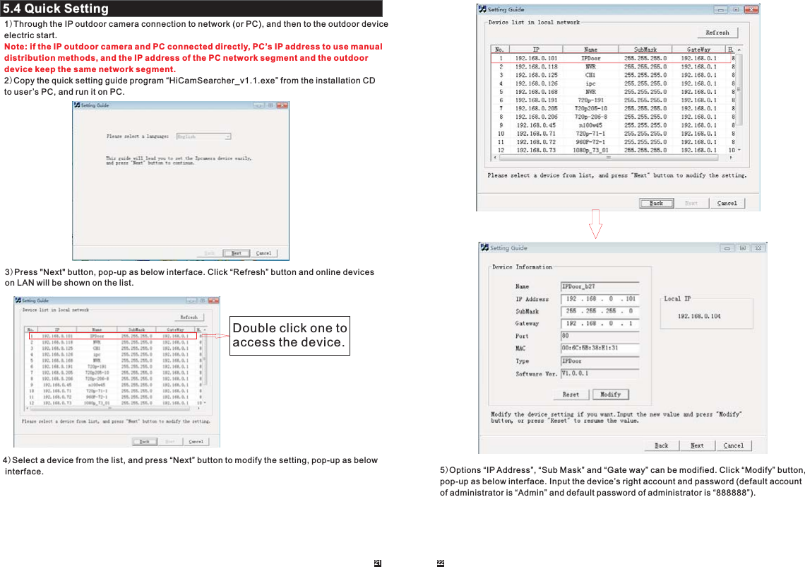
![A. LAN Settings[IP Type]: There are two options: “Fixed IP Address” and “dynamic IP Address”.After selecting an Internet connection setting - such as fixed IP address (static) or dynamic IP address (DHCP) – and allocating a port, users can access the IP outdoor camera remotely via the Internet. 1)If fixed IP address has been selected, it is necessary to set up an IP address, a subnet mask and a gateway. [IP Address]: Enter the IP address in this field.[Subnet Mask]: Input numbers for the subnet mask.[Gateway]: Enter numbers for the default gateway.[DNS Type]: Options include “Manual DNS” and “From DHCP Server”. If users select “Manual DNS”, they have to input numbers for primary DNS and second DNS manually. 2)If DHCP is selected, the server will allocate an outdoor camera IP address automatically.NOTE: Save the IP address when selecting DHCP and the outdoor camera will automatically connect with the server. It will allocate an IP address when the connection is stable, and this address will be displayed on the interface.B. HTTP[HTTP Port]: The IP address identity one outdoor device in the network, you can run several programs on this equipment, and every program will transfer the data through some port, in factdata is transferred from one port to another. The port setting of this page is asking user choosewhich port to transfer the data for the web server. Doing port mapping, need to maintainconsistent with the port (equipment factory default port is 80).Sets up a Web browser port via HTTP. The default port number is “80”.[Mobile port]: Mobile monitoring port. And default value is 20510.C. Network Test[Wan Test]: In this field, users can fill in the IP address or DDNS address which they set up, and click “ ” to test the network traffic is normal or not. If all the network parameters are set correctly, click “ ” and “Test Success!” will be shown. Otherwise “Test Failure!” will be shown. 5.7.3.1 Network--Basic SettingsClick “Parameters—Network—Basic Settings” to enter the LAN Settings interface. Default IPtype is “dynamic IP Address”. The user can set up device network parameters through the operation “Quick Setting Guide”, user can change it according to your network environment.5.7.3.2 Network--DDNSClick “Parameters-Network-DDNS”to enter the DDNS setting interface. DDNS setup as follows.User can use third part DDNS, first user must have a domain name; www.dyndns.org or www.3322.org is recommended. Please remember the username, password and domain name.Then enable DDNS, for example, select the DDNS Provider as “3322.org”. If your domain name is “test.f3322.org”, please enter “test.f3322.org” in the option “Your Domain”, the “Username” and“Password” is the username and password that applied in the www.3322.org. Click “ ” tosave. Then you can access the device by domain name.5.7.3.3 Network--Wifi(Optional, please take actual machine as quasi)For the outdoor device with WIFI function, users can visit the device remotely by the following methods: through network cable connection or through wireless connection. If through wireless connection, please use the network cable to connect the device into LAN before doing settings of wireless connection. Then click “Parameters—Network—WiFi” to enter the Wifi Setting interface, and according to the below 1-6 steps to do the settings.1) Open wireless, “ ” indicates WIFI status to be enabled.2) Click the “ ” button to search the current wireless routers, and all the wireless routers will appear on the Current Hot Point list.3) Choose one effective router, click it to choose router SSID.4) Input correct password of the wireless router in wireless security mode.5) Click “ ” to check the wireless network is connected successfully or not.6)When the wireless is connected successfully, click “ ” to save the settings, the devicewill be reboot automatically, take away the Ethernet cable, then the wireless network will workperfectly.Note: 1. When adjust WIFI status, the device will be reboot after saving the setting. 2. When enable WIFI status, the device will be reboot automatically if plug or unplug the network cable connected to the outdoor device. 3. Through Wifi connection, the “Network Type” on the Network Basic Setting suggested to be set as “DHCP”. When configure the parameters about WIFI, user can view the outdoor device can be allocated IP address whether or not through the search tool “HiCamSearcher”. 29 30](https://usermanual.wiki/LB-Technology/96223W-CP/User-Guide-2396910-Page-16.png)
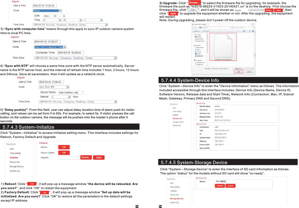
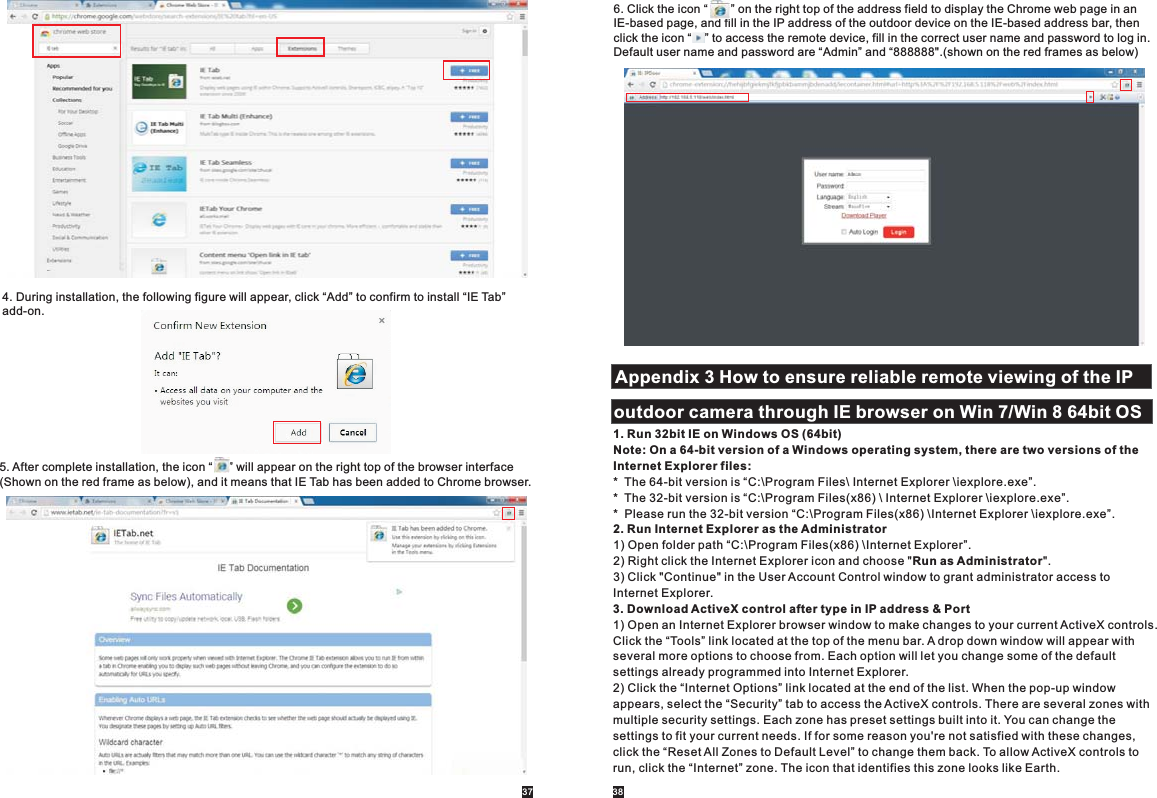
![5.7.5 LogoutClick “Logout” to log out of the system.5.7.4.6 System-System LogClick “System—System Log” to enter the “system log” menu as follows.At the top of the “Log Search” page are the following filters to facilitate locating the desired file(s):[Time]: Set the starting time and the ending time of the log being searched for.[Type]: Choose from the following options: “All”, “Alarm” and “Operation”.Click the “ ” button after setting the log time and type, and the system will display the selected log in the list. Click “ ”, “ ”, “ ”, “ ” to navigate pages, and click “ ” to delete all the log lists. 361.First, install Firefox on Windows(This document will use Firefox 28.0 as an example). 2. After installing Firefox, please search for the “IE Tab” add-on for Firefox, which can be downloaded from Firefox browser.3. Open Firefox, click “Tools-->Add-ons” to enter into the interface of “Get Add-ons”, and search for “IE Tab”, all the IE tabs will be shown on the list for “Available Add-ons”. Choose one and install it, this document will use IE Tab 2(FF 3.6+)5.12.12.1 for example.4. After installing the IE Tab, user need restart Firefox browser.5. Open Firefox and enter the outdoor device IP address in the address field. Right-click at blank,select “View Page in IE tab”. The outdoor device can now be connected successfully.Appendix 1. Accessing the IP outdoor camera via Mozilla Firefox1.First, installing Google Chrome Browser on Windows(this manual will use Chrome version 34.0.1847.116 m as an example).2. After installing Google Chrome, search for the “IE Tab” add-on for Chrome, which can be downloaded from the Chrome Web Store.3. Opening Chrome, click “ Customize and control Google Chrome->Tools->Extensions->browser the gallery” to enter the “Chrome Web Store” interface to search for “IE Tab”, and results for IE tab in Extensions will appear on the right side. Choose one to install it and it’s free for installation(Shown as below). Appendix 2. Accessing the IP outdoor camera via google Chrome35](https://usermanual.wiki/LB-Technology/96223W-CP/User-Guide-2396910-Page-19.png)