LB Technology 96223W-CP IP VIDEO DOOR PHONE User Manual
LB Technology Co., Ltd. IP VIDEO DOOR PHONE Users Manual
Users Manual

OPERATION INSTRUCTION
IP Video Door Phone
User Manual
MC-1054(A-3)

LIMITATION OF LIABILITY
This users' manual is supplied 'as is', with no warranties, be it expressed or implied, including,
but not limited to, the implied warranties of merchantability, suitability for any exact purpose, or
non-infringement of any third party's rights.
This publication may include technical inaccuracies or typos. The manufacturer holds the right
to introduce any changes to the information contained herein, for any purpose, including but not
limited to, improvements of the publications and/or related to the product, at any time, without
prior notice.
※
※
DISCLAIMER OF WARRANTY
The supplier shall not be liable to any party or any person, except for replacement or reasonable
maintenance of this product, for the cases, included but not limited to the following:
Any damage or loss, including but not limited to: direct/indirect, consequential, special, exemplary,
arising out of or related to the product;
Inappropriate use or negligence of the user in operation of the product, resulting in personal injury
or any damage;
Unauthorized disassembly, repair or modification of the product by the user;
Any problems or consequential inconvenience, loss or damage, caused by connecting this product
to devices of the third parties;
Any claim or action for damages, brought by any photogenic subject, be it a person or organization,
due to violation of privacy whereby the pictures taken by the device and/or saved data become
public or are used for the purposes other than intended.
※
※
※
※
※
SAFETY INSTRUCTIONS
1 2
Read these instructions and keep them in a safe place for future reference.
Please refer all work related to the installation of this product to qualified service personnel or
system technician.
Do not operate the appliance beyond its specified temperature, humidity or power source ratings.
Securely install the devices on vertical surfaces (solid walls/doors) not prone to vibration or impact.
Install the devices away from heat sources such as radiators, heat registers and stoves.
Installation of the terminal near consumer electronics devices, e.g. stereo receiver/amplifiers and
televisions, is permitted as long as the air surrounding the terminal does not exceed the above
mentioned temperature range.
Handle the appliance with care. Do not strike or shake, as this may damage the device.
The doorbell/camera units should be fitted with an approved weather shield if the chosen position
is in direct sunlight, or in contact with rain, snow or irrigation sprinkler systems.
Do not use strong or abrasive detergents when cleaning the appliance body. When the dirt is
hard to remove, use a mild detergent and wipe gently.
Do not overload outlets and extension cords as this may result in a risk of fire or electric shock.
Distributing, copying, disassembling, reverse compiling, reverse engineering, and also exporting
in violation of export laws of the software provided with this product, is expressly prohibited.
※
※
※
※
※
※
※
※
※
CARING FOR THE ENVIRONMENT BY RECYCLING
When you see this symbol on a product, do not dispose of the product
with residential or commercial waste.
Recycling your electrical equipment
Please do not dispose of this product with your residential or commercial waste. Some countries or
regions, such as the European Union, have set up systems to collect and recycle electrical and electronic
waste items. Contact your local authorities for information about practices established for your region.
COPYRIGHT STATEMENT
All rights reserved. No part of this publication may be reproduced in any form or by any means,
transcribed, translated into any language or computer language, transformed in any other way,
stored in a retrieval system, or transmitted in any form or by any means, electronic, mechanical,
recording, photocopying or otherwise, without the prior written permission of the owner.

LIMITATION OF LIABILITY..............................................................................1
DISCLAIMER OF WARRANTY.........................................................................1
SAFETY INSTRUCTIONS...............................................................................1
CARING FOR THE ENVIRONMENT BY RECYCLING........................................2
COPYRIGHT STATEMENT..............................................................................2
Table of Contents ...........................................................................................3
1. Description Of IP Outdoor camera................................................................5
1.1 Feature(Please take actual model as quasi).............................................5
1.2 Specifications.......................................................................................5
1.3 Fitting of the IP Outdoor Camera.............................................................6
1.4 Wiring Diagram of the IP Outdoor Camera................................................6
1.5 Installation process of Outdoor Units.......................................................7
2. Device Connect--Through wired network or wireless network(optional)............................8
3. Soft AP Function.........................................................................................8
4. Mobile Phone Software Visit ......................................................................10
4.1 Iphone Mobile or Ipad ..........................................................................10
4.2 Android Mobile ....................................................................................14
5. Web Browser Operation For IP Outdoor Camera...........................................18
5.1 Running Environment ..........................................................................19
5.2 Network Security Setting......................................................................19
5.3 Connection Settings ............................................................................20
5.4 Quick Setting.......................................................................................21
5.5 System Login ......................................................................................23
5.6 Port Forwarding ..................................................................................25
5.7 Function Settings................................................................................26
5.7.1 Home..........................................................................................26
5.7.2 Media .........................................................................................27
5.7.2.1 Media--Video....................................................................27
5.7.2.2 Media--OSD .....................................................................28
5.7.3 Parameters .................................................................................28
5.7.3.1 Network--Basic Settings ...................................................29
5.7.3.2 Network--DDNS ...............................................................30
5.7.3.3 Network--Wifi(Optional, please take actual machine as quasi) ............30
5.7.3.4 Event--Record(Optional)...................................................31
5.7.4 System...................................................................................... 32
5.7.4.1 System-User.................................................................... 32
5.7.4.2 System-Time Setting.........................................................32
5.7.4.3 System-Initialize .............................................................. 33
5.7.4.4 System-Device Info...........................................................34
5.7.4.5 System-Storage Device.....................................................34
5.7.4.6 System-System Log..........................................................35
5.7.5 Logout.........................................................................................35
Table of ContentsTable of Contents
Appendix 1. Accessing the IP outdoor camera via Mozilla Firefox .....................35
Appendix 2. Accessing the IP outdoor camera via Google Chrome ....................36
Appendix 3. How to ensure reliable remote viewing of the IP outdoor camera through IE brows er on Win 7/ Win 8 64bi t OS..38
3 4
User Manual
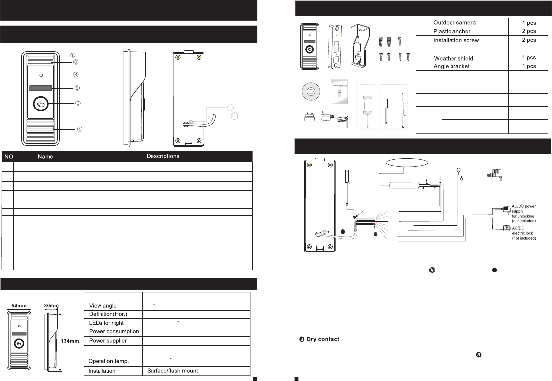
1.1 Feature(Please take actual model as quasi)
1. Description Of IP Outdoor camera
6
5
1 Weather shield Affix and protect outdoor camera from rain or snow.
2 IR LEDs Provides illumination with IR LEDs for better visibility.
3 Camera Capture image to transmit to display
4 Speaker Sound from smart-phone
5 Call button Visitor call for intercommunication
6 Microphone Transmit voice to smart-phone
1.2 Specifications
1.0M
IR LEDs(60 )
60
300mA max.
Camera 1/4 CMOS
External switching power supply DC 12V.
-40~+50 C
Network Interface 10/100M
1.3 Fitting of the IP Outdoor Camera
s
Affixation screws3 pcs
1.4 Wiring Diagram of the IP Outdoor Camera
In the standard delivery the system support locks with Normally Open(N.O.) door unlocking
method. It means that in the normal state the dry contact(marked as ) is opened, so the lock
is kept under constant closed state. If the unlocking button is pressed and the dry contact is
changed to closed, then the lock is released.
Installation CD(with full manual and
android mobile phone software)
User quick guide
External Switching Power Adapter
1 pcs
1 pcs
1 pcs
System port
7
The terminal is defined functionality as below:
1.GN&WH: To network wire GN&WH 2.GN: To network wire GN
3.OG&WH: To network wire OG&WH 4.OG: To network wire OG
5.RD: DC 12V 6.BK: GND 7/8.BN: To door lock.
Note:
GN--Green, WH--White, OG--Orange, RD--Red, BK--Black, BN--Brown
8Volume regulator To be used to adjust the speaker volume. If the speaker volume is too low, how to increase it?
At the backside of outdoor unit, you can find out a regulator (Marked as ) which is used to
adjust the speaker volume, turn the regulator with the screwdriver to decrease/increase the
speaker volume.
b
7
8
Antenna
(optional)
Indoor antenna(optional)
Outdoor antenna(optional)
1pcs(6dBi or 3dBi)
1pcs(10dBi)
or
Indoor antenna
(optional)
Outdoor
antenna
(optional)
or
Antenna(optional)
For the models with wired function, connect the doorbell to external
switching power supply(DC 12V), ethernet cable and door lock.
For the models with wireless function, connect the doorbell to external
switching power supply(DC 12V), door lock and indoor antenna or
outdoor antenna, and antenna can be optional.
Antenna(optional)
Antenna connector
(optional)
External switching power supply
DC 12V
1.GN&WH
2.GN
3.OG&WH
4.OG
5.RD:DC 12V
6.BK:GND
7.BN
8.BN
+
-
GN&WH
GN
OG&WH
OG
Network Cable
To Internet
b
7 8
* Avoid installation of the device near strong radiation e.g. AC motor and lift.
* Maintenance should be complied with qualified technician.
* Avoid hard shake, beating and collision, otherwise the internal exact components maybe
be damaged.
* Do not expose the outdoor camera under strong light or sunshine.
* Do not install the outdoor camera in the environment e.g. direct sunlight, contact rain,
High temperature, high humidity, full of dust and chemistry corrosive.
* Select the most suitable position where the camera is located at user’s eye level.
* Switch off power supply before installation.
* Keep more than 30cm away from AC power supply to avoid external interference.
* Keep it away from the water and magnetic field.
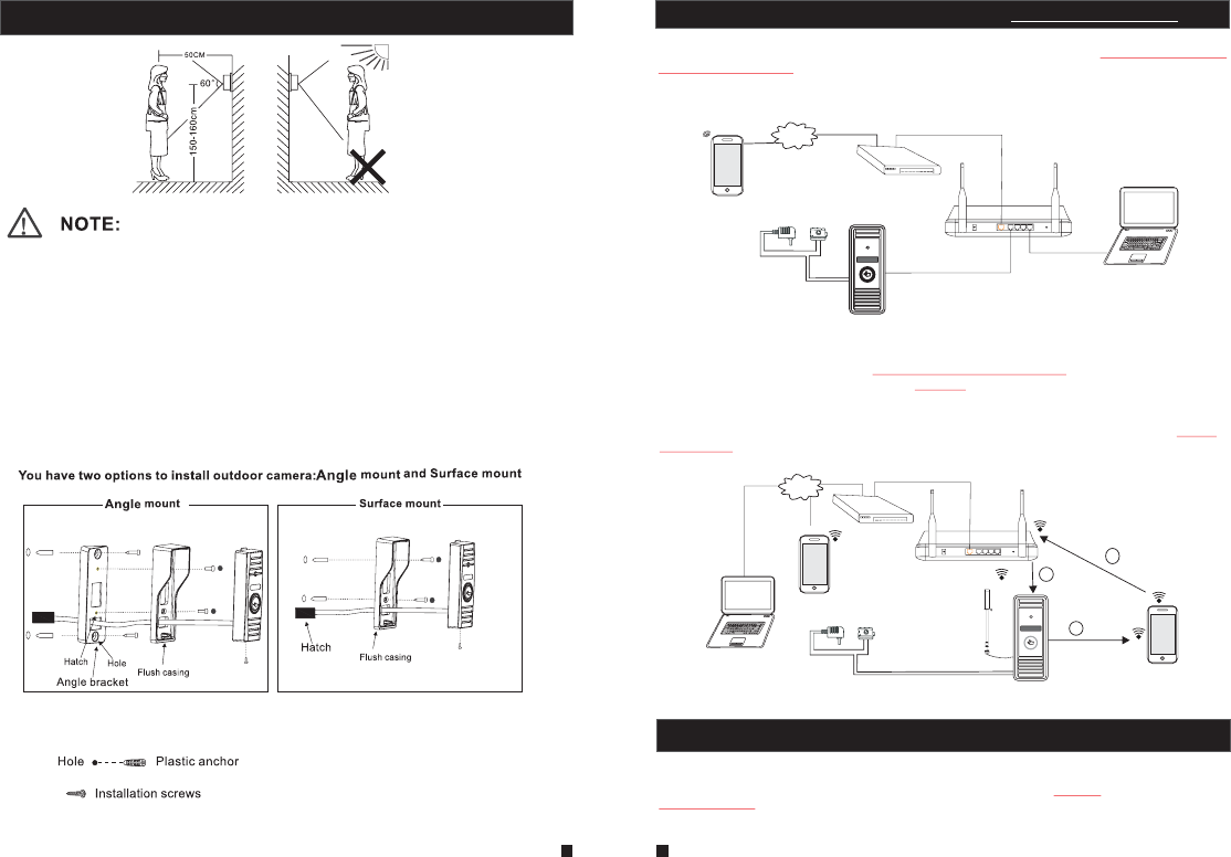
Please follow these steps as reference:
1.Select the most suitable position where the outdoor camera is located at user’s eye level, then
drill 2 holes according the weather shield, embed 2 plastic anchors into the holes.
2.Use a screwdriver to affix the weather shield with the installation screws.
3.Drag the connection cable through the hatch at the bottom side.
4.Embed the outdoor unit into the weather shield and affix with the supplied screws.
2.2 Tool Bar
2. Device Connect--Through wired network or wireless network(optional)
A. User can connect the outdoor camera through network cable, operation steps:
1. Connect the network cable to the outdoor camera according to section
.
2. Connect the power adapter to the electrical outlet of the outdoor camera and power on.
3. Wait for a while until hearing a beep, this time the outdoor camera starts completely.
Network connection diagram through wired network as Figure 1.
1.4 wiring diagram of
the IP outdoor camera
B. The device with WIFI function can be also work with WIFI wireless network.
1. If user connects a network cable to the outdoor camera, the parameters for WIFI can be set up
via web browser, please see section for more information,
network connection diagram please refer to on the above.
2. If user doesn’t want to connect a wired cable to the device, and user needs to prepare a
wireless router and a smart-phone or a pad with IOS or Android system. The parameters for WIFI
can be set up via a smart-phone or a pad with IOS or Android system, please see section
for more information.
Network connection diagram via wireless network as Figure 2.
5.7.3.3 Network--WIFI(optional)
Figure 1
3. Soft
AP function
Figure 2
Figure 1
DOOR
AC/DC power lock
(not Included) (not Included)
Router
Internet
Reset
WAN
LAN
3G/WIFI
IOS/Android
To WAN
To LAN To LAN
Modem
PC
3. Soft AP Function
The outdoor camera with wifi function can be worked in wireless mode. If user doesn’t want to connect a wired
cable to the device, and user need prepare a wireless router and a smart-phone or a pad with IOS or Android
system. The network connection diagram via wireless network please refer to on section
Figure 2
2.Device Connect.
1.5 Installation process of Outdoor Units
DOOR
AC/DC power lock
(not Included) (not Included)
WIFI(LAN)
IOS/Android
Reset
WAN
LAN
Internet
To WAN
AP mode
WIFI
(LAN)
WIFI(LAN)
WIFI(LAN)
1
2
3
3G/WIFI
IOS/Android
Modem
Router
PC
Antenna
(optional)
Antenna connector
(optional)
1) First user must install a mobile operating system specific program onto his mobile or pad. The Android mobile
10
9
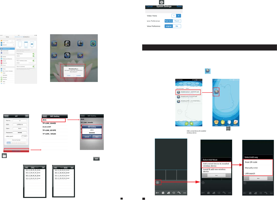
4.1 Iphone Mobile or Ipad
The iPhone or iPad application, like all iPhone or iPad applications, needs to be downloaded
directly from the App Store. Open APP store, search for “MobileEyeDoor+”, it's a free application.
The application on the iPad could be searched for “iPad Only” or “iPhone Only”.
(1) “MobileEyeDoor+” installation
According to the following method, open the App store “ ”, touch “ ” and search for
“MobileEyeDoor+”. Install it on the mobile phone or the iPad. After installing “MobileEyeDoor+”,
it will appear a “ MobileEyeDoor+” icon on the application software.
(2)
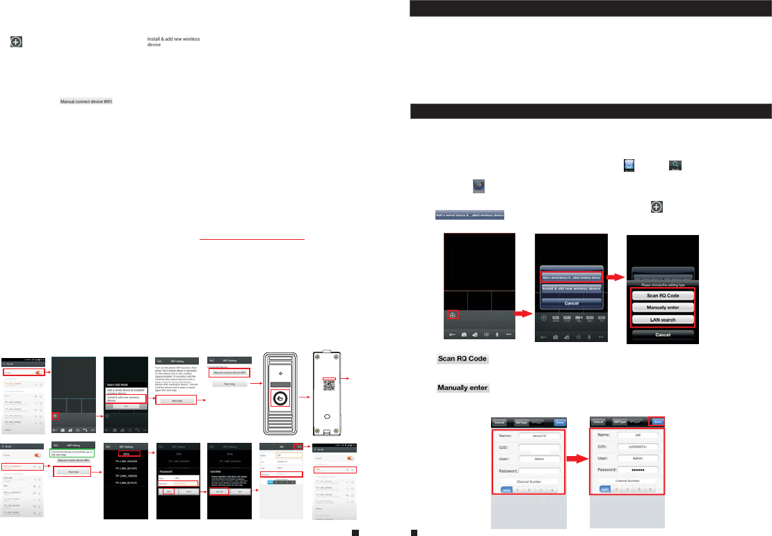
Click the “MobileEyeDoor+” icon to run the program. Click “ ” to add a new device, first
click “ ” to the interface to choose the adding type, there are three methods
to add device: “Scan QR Code”, “Manually enter” and “LAN Search”.
How to use “MobileEyeDoor+”
1>
A. Adding by “Scan QR Code”
Click “ ” to the next interface, users can scan QR code attached to the machine
through the mobile phone or the iPad, and the device UID will be shown.
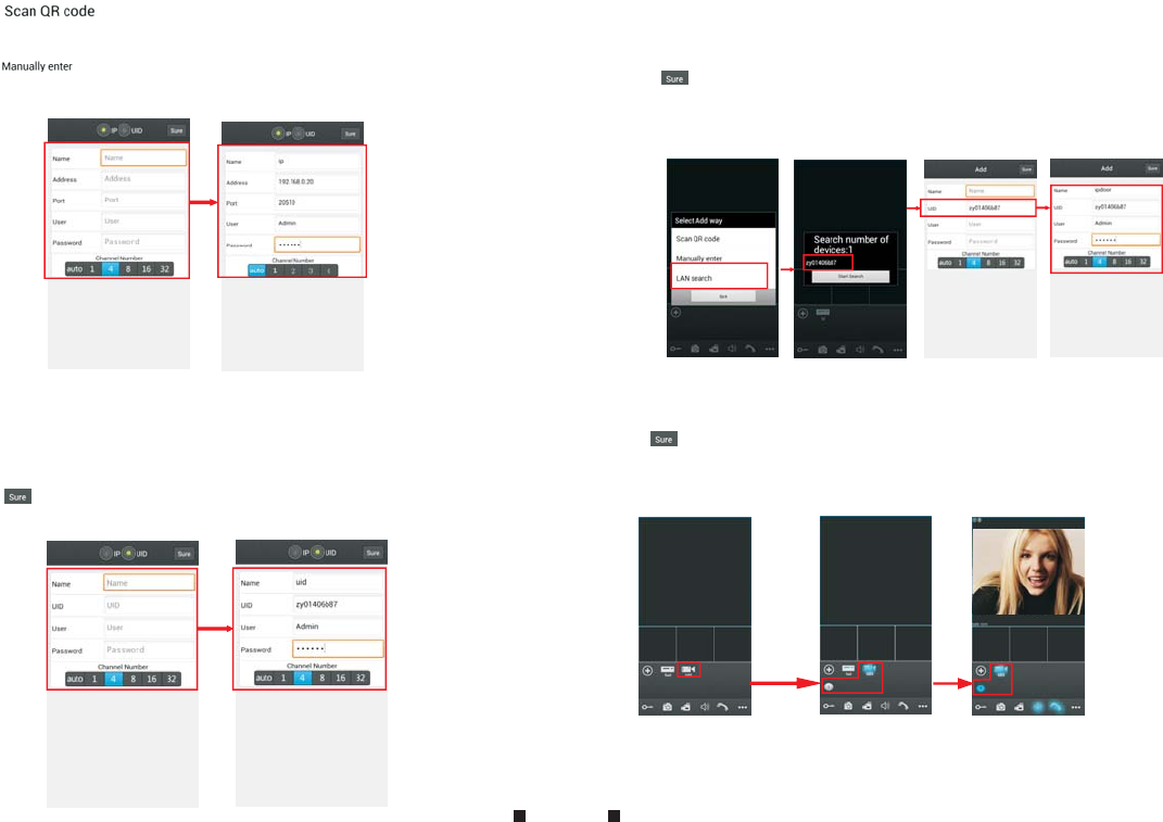
B. Adding by “Manually enter”
Click “ ” to the next interface, users can add a new device by UID type or by IP type.
a.By UID type
After entering the “UID Type” Settings menu, the following fields will need to be completed:
4. Mobile Phone Software Visit
This IP video door phone can transmit live feed to your mobile phone, and support P2P for
mobile monitoring, so that you can have 'on the go' access to your surveillance system from
virtually anywhere. To view, you must install a mobile operating system specific program into
your mobile. Currently, there are a limited number of phones that are supported: Google
Android and Apple iPhone or iPad. The Android mobile program is located on the included CD
or downloaded via “Play Store”, and an iPhone mobile program or an iPad program is
downloaded via “APP Store”. In “APP Store” or “Play Store”, please search for “MobileEyeDoor+”.
Please see the instruction manual for your mobile to install the program.
program is located on the included CD or downloaded via “Play Store”, and the iPhone or iPad program should
be downloaded via “APP Store”. In “Play Store” or “APP Store”, please search for “MobileEyeDoor+” and install
it onto user’s mobile or Pad. Please see the instruction manual for user’s mobile to install the program.
2) Second turn on user’s phone WLAN function, then click the “MobileEyeDoor+” icon to run the program, click
“ ” to select add mode, here must select “ ” to the next interface to add wireless device.
3) Then long-press the “call” button on the outdoor camera, don’t loosen the button until hearing a beep, this
means the device will reboot automatically and go into AP mode. Wait for a moment, when hearing another
beep it means the device starts successfully and goes into AP mode.
4) On “WIFI setting” interface, wait for a moment and phone with android system can be connected to the device
WIFI successfully automatically. For the phone with IOS system user need to connect device WIFI function
manually. Click “ ” to enter WLAN interface of user’s phone to see available networks, and UID
number of the device(the UID is attached to the machine) will be shown on the available networks list.
Select it and connected successfully means the mobile will be connected to the outdoor camera directly(shown
as follows).
5) On this interface, Return to the “WIFI setting” interface and go to the next step. available wireless devices will
be shown on the list. Choose one and click it, if the wireless password of the wireless router is enabled, it will
pop-up a window to enter the password of the wireless router, input the correct password and setting ok, the
outdoor device will reboot automatically, it will be connected to the wireless router after starting when hearing a
beep again.
7) Return to the WLAN settings on the mobile and choose the wireless router which the outdoor device has been
connected to. Now the wireless function of the outdoor camera has been activation and works normally(Shown
as follows).
6) Click “Next Step” to add outdoor device, input the correct password of the device, default as “888888", and then
save.
2. When the device went into AP mode, long-press the “Call” button again, don’t loosen the button until
hearing a beep, this means the device will reboot automatically and will return to the previous
connection mode.
For more details of “MobileEyeDoor+”, please refer to Section .4. Mobile Phone Software Visit
1. If the device has went into AP mode, but the wireless function of the device hasn’t been activation via
“MobileEyeDoor+” on the phone or user doesn’t do any operate about the device, after 10 minutes the
device will automatically exit AP mode and returns to the previous connection mode.
Note:
In the following diagram, we use a smart-phone with android system to an outdoor camera. The
usage of an iPhone/iPad with IOS system is similar.
UID: zz0280a1cb
11 12
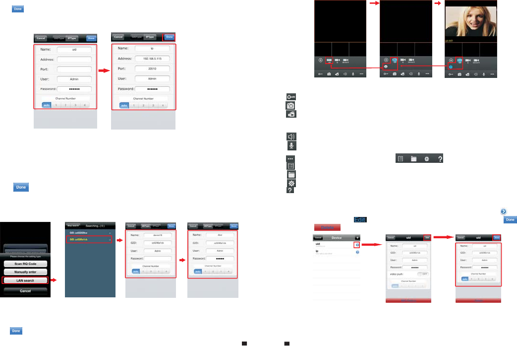
Click “IPType” to enter the Settings menu, the following fields will need to be completed:
b. By IP type
Name: Set name for the outdoor device, and saves settings for future usage.
Address: The public IP address or dynamic domain name of the outdoor device.
Port: The mobile port of the outdoor device for remote access viewing via mobile phone or
iPad, the default is “20510”.
User: The user name set for entering the outdoor device system. (Admin by default)
Password: The password set for entering the outdoor device system. (888888 by default)
Channel Number: Select the max channels of the device will be connected.
Click “ ” to save.
C. Adding by “LAN Search”
On LAN, turn on the WIFI of the Wireless Router and the mobile phone(or the ipad). Click
“Local Search” and online devices will appear on the “Please choose the device” list, click
one to add the device, the following fields will need to be completed:
Name: Set name for the outdoor device, and saves settings for future usage.
User: The user name set for entering the outdoor device system. (Admin by default)
Password: The password set for entering the outdoor device system. (888888 by default)
Channel Number: Set the max channels of the device will be connected.
Click “ ” to save.
2> After adding the device successfully, the device will appear on the main screen. Click the
device, and all the channels of the device will be shown on the screen. Click any channel and
it will connect immediately. The background of the channel will be highlighted after connecting
successfully(shown as follows).
3> The functions of the other icons on the live view:
Unlock.
Snapshot .
: to capture a frame of the video stream as a still photo
Record: Click it to start manual record video on the current channel, and the right top corner
of the channel has a normal recording video symbol “[REC]”. And click it again to stop manual
record.
Click it to turn the sound on or disable.
Click it to start to talk, and the background of the button will be highlighted. Click it again to
stop talking.
Click it to display or hide the buttons “ ”.
Click it to enter the device list interface.
Click it to enter the snapshot file and record file.
Click it to enter the local setting interface.
Click it to enter user guide interface.
4> On the live view, users can touch a channel on the screen and drag it to the other channel
position directly.
5> On the interface of “Device”, user can edit the parameters of one device, click “ ” to the next
interface as below. Click “ ” to enter edit mode to adjust the parameters. Click “ ” to save.
And click “ ” to remove the information of the current device.
[Video Push]: To access the interface about the parameters of one device, there is an option
“video push” for alarm push function. When select “On”, it indicates that the alarm push function of
the current device is enabled. To enable alarm push function, users need to make sure the outdoor
Name: Set name for the outdoor camera, and saves settings for future usage.
UID: The device UID (UID is attached to the machine).
User: The user name set for entering the IP outdoor device system. The default is “Admin”.
Password: The password set for entering the outdoor device system. The default is “888888".
Channel Number: Set the max channels of the device will be connected.
Click “ ” to save.
IPDoo r 2014-07-25 10:30:32
13 14
device and the mobile phone are both connected to internet.
Note: 1) The alarm push function can be effective, and the device must be added by UID type.
2) For the phone with iOS system, please go into “Settings->Notification Center” on you phone,
click on “MobileEyeDoor+” and make sure you have “Badge APP Icon, Sounds, Shown in
Notification Center” enabled. Also make sure you have “Shown on Lock Screen” enabled.
3) When the option “video push” on the mobile software interface is set to “On”, someone
press the call button on the outdoor camera, the notification message will be pushed onto the
master’s phone or iPad(Shown as below figure). And users can click the alarm list to access to the
video live view of the channel directly or access to the video live view to unlock for the outdoor
camera .
[WIFI Setting]: To access the interface about the parameters of one device, there is an option
“WIFI Setting” for the outdoor device. Click “WIFI setting”, and available wireless devices will be
shown on the list. Choose one and click it, if the wireless password of the wireless router is enabled,
it will pop-up a window to enter the password of the wireless router, input the correct password
and setting ok, the outdoor device will reboot automatically, it will be connected to the wireless router
after starting when hearing a beep again.
Note: If users want to connect the device via wireless network, when the device restarts
automatically after completing set of the parameters about WIFI, please unplug the Ethernet cable
connected to the device, otherwise the device will run via wired network.
6>
Click one on the list to see the picture or the record.
Click “ ” to enter the snapshot and record file interface. Click “Photos” or “Records” to switch
display interface. Click “ ” to enter edit
mode, users can remove the file list that they want to.
1) Please go to the android software market “Play Store” to search for “MobileEyeDoor+” and
install it. Or from the installation CD, copy the setup software “MobileEyeDoor+.apk” to user's
Android phone or to SD card.
Open your “File Manager” in android phone, and find out the file “MobileEyeDoor+” in your
android phone memory or SD card. Click it to install the software. When the application has
finished installing, the icon “MobileEyeDoor+ ” will display on the screen of the phone (shown
as below).
4.2 Android Mobile
7> Click “ ”to enter the “System Settings” interface as follows.
[Video Views]: Select “1" and only one channel view will be shown
on live view. Select “4" and quad channels view will be shown on
live view.
[Live Preference]: Options include “Real-time” and “Quality”. If
choose “Real-time”, the video encoder of the channel for remote
access viewing via mobile phone will consider to the frame first;
If choose “Quality”, the video encoder of the channel for remote access viewing via mobile
phone will consider to the image quality first.
[View Preference]: To set up the image display size when view the channel video. Options
include “”original” and “tile”.
2)Click the “MobileEyeDoor+” icon to run the program, click “ ” to add a new device, first please
choose the adding mode, click “ ” to the interface to select adding type, there are
three methods to add device: “Scan QR code”, “Manually enter” and “LAN Search”.
A. Adding by “Scan QR code”
Click “ ” to the next interface, users can scan two-dimensional code attached
to the machine through the mobile phone, and the device UID will be shown.
B. Adding by “Manually enter”
Click “ ” to the next interface, users can add a new device by UID type or by IP type.
a. By IP type
After entering the “IP” Settings menu, the following fields will need to be completed:
Name: Set name for the outdoor camera, and saves settings for future usage.
Address: The public IP address or dynamic domain name of the outdoor device.
Port: The mobile port of the outdoor device for remote access viewing via mobile phone, the
default is “20510”.
User: The user name set for entering the outdoor device system. (Admin by default)
Password: The password set for entering the outdoor device system. (888888 by default)
Channel Number: Select the max channels of the device will be connected.
Click “ ” to save.
b. By UID type
Click “UID” to enter the Settings menu, the following fields will need to be completed:
15 16
Name: Set name for the outdoor device, and saves settings for future usage.
UID: The device UID (UID is attached to the machine).
User: The user name set for entering the outdoor device system. The default is “Admin”.
Password: The password set for entering the outdoor device system. The default is “888888".
Channel Number: Set the max channels of the device will be connected.
Click “ ” to save.
C. Adding by “LAN Search”
On LAN, turn on the WIFI of the Wireless Router and the mobile phone. Click “LAN Search”
and online devices will appear on the “Search number of device” list, click one to add the
device, the following fields will need to be completed:
Channel Number: Set the max channels of the device will be connected.
Click “ ” to save.
3) After adding the device successfully, the device will appear on the main screen. Click the
device, and all the channels of the device will be shown on the screen. Click any channel and
it will connect immediately. The background of the channel will be highlighted after connecting
successfully(shown as follows).
Name: Set name for the outdoor device, and saves settings for future usage.
User: The user name set for entering the outdoor device system. The default is “Admin”.
Password: The password set for entering the outdoor device system. The default is “888888".
IPDoo r 2014-04-24 10:20:30
17 18
4) The functions of the other icons on the live view:
Unlock.
Snapshot .
: to capture a frame of the video stream as a still photo
Record: Click it to start manual record video on the current channel, and the right top corner
of the channel has a normal recording video symbol “[REC]”. And click it again to stop manual
record.
Click it to turn the sound on or disable.
Click it to start to talk, and the background of the button will be highlighted. Click it again to
stop talking.
Click it to display or hide the buttons “ ”.
Click it to enter the device list interface.
Click it to enter the snapshot file and record file.
Click it to enter the local setting interface.
Click it to enter user guide interface.
5) On the live view, users can touch a channel on the screen and drag it to the other channel
position directly.
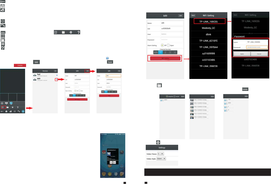
6) On the interface of “Devices”, user can edit the parameters of one device, click “ ” to the next
interface as below. Click “ ” to enter edit mode to adjust the parameters. Click “ ” to save.
And click “ ” to remove the information of the current device.
[Alarm Setting]: To access the interface about the parameters of one device, there is an option
“Alarm Setting” for alarm push function. When select “Open”, it indicates that the alarm push function
of the current device is enabled. To enable alarm push function, users need to make sure the
outdoor camera and the mobile phone are both connected to internet.
Note: 1) The alarm push function can be effective, and the device must be
added by UID type.
2) When the option “Alarm Setting” on the mobile software interface is
set to “On”, someone press the call button on the outdoor camera, the
notification message will be pushed onto the master’s phone(shown as
the right figure). And users can click the alarm list to access to the video
live view of the channel directly or access to the video live view to unlock
for the outdoor camera.
[WIFI Setting]: To access the interface about the parameters of one device,
there is an option “WIFI Setting” for the outdoor device. Click “WIFI setting”,
and available wireless devices will be shown on the list. Choose one and
click it, if the wireless password of the wireless router is enabled, it pop-up a
window to enter the password of the wireless router, input the correct
password and setting ok, the outdoor device will reboot automatically, it will be connected to the
7) Click “ ” to enter the snapshot and record file interface. Click “snapshot” or “record” to switch
display interface. Click “ ” to enter edit
mode, users can remove the file list that they want to.
Click one on the list to see the picture or the record.
wireless router after starting when hearing a beep again.
Note: If users want to connect the device via wireless network, when the device restarts
automatically after completing set of the parameters about WIFI, please unplug the Ethernet
cable connected to the device, otherwise the device will run via wired network.
8) Click “ ”to enter the “Settings” interface as follows.
[Video Views]: Options include “1" and “4". Select “1" and only one
channel view will be shown on live view. Select “4" and quad channels
view will be shown on live view.
[Video Style]: Options include “Original” and “Covered”.
5. Web Browser Operation For IP Outdoor Camera
2.1 Mouse Control
Users could set up parameters for the stand-alone IP outdoor camera via Web browser.
Install the software through the Internet browser of OS to conveniently operate the network
from a remote location. This device supports C/S, B/S, and access in LAN and WAN. It also
supports IP and domain name visiting.
IMPORTANT! SOFTWARE RECOMMENDATIONS:
To ensure reliable remote viewing of IPdoor footage, it is highly recommended that users have
either Windows XP, Windows 7 or Windows 8 installed on their computers, and that they use
either Internet Explorer 6.0, Internet Explorer 7.0, Internet Explorer 8.0, Internet Explorer 9.0
Internet Explorer 10.0, Internet Explorer 11.0, Mozilla Firefox, or Google Chrome as their
Internet browser. (In the appendix, there is an explanation of how to access the IP outdoor
camera using Firefox or Google Chrome.)
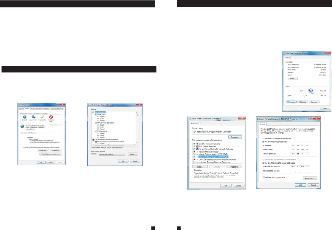
Prior to setting up remote access, set the network security level by following the following
instructions:
(1) Open the Internet Explorer browser and click the “Tools” tab located in the bar at the top
of the browser; from the drop-down menu, select “Internet Options”.
(2) Click the “Security” tab in the dialogue box.
(3) Click “Custom level” (at the bottom of the dialogue box) to set the security level.
Note: Suggested that to run Internet Explorer browser as Administrator on operation
system such as Windows 7/Windows 8/Windows 8.1 except Window XP.
5.1 Running Environment
5.2 Network Security Setting
Set the appropriate settings for the ActiveX controls and plug-ins. Find the following controls
in the “Security Settings” box and select the “Enable” option for each of them. This is an
extremely important step.
* Automatic prompting for ActiveX controls.
* Binary and script behaviors.
* Initialize and script ActiveX controls not marked as safe for scripting.
* Download signed ActiveX controls.
* Download unsigned ActiveX controls.
* Run ActiveX controls and plug-ins.
* Script ActiveX controls safe for scripting.
Prompt: Before setting up remote access, turn Disable the firewall and any anti-virus software
currently running on the computer.
Remote access to the IP video door phone is carried out over the Internet. In the local area
network, the IP address of the client-side computer must be in the same network segment that
the IP address of the IP video door phone. In the wide area network, the only requirement is
that the two sides can visit the public network and connect to the Internet through the IP
address or the dynamic domain name. The following will mainly focus on connecting and
setting up the local area network.
Step 1: Right-click on “Network Neighborhood” and click “Properties” in the menu to open the
“Network Connections” menu. Alternatively, if the operating system being used does not have
a “Network Neighborhood” icon, enter the Control Panel found in the “Start” menu; then, click
“Network and Internet”, and select “Network and Sharing
Center.” On the “Network and Sharing Center” page, there
should be a “Network” section; in that section, there should be
a “View Status” link next to a listing that reads “Connection:
Local Area Connection.” Click the “View Status” link. A small
“Local Area Connection Status” window will appear; at the
bottom of this screen, click “Properties”, and if prompted to
give permission to continue, click “Yes.”
Step 2: Double-click to open “Local Area Connection” from the
“Network Connections” menu.
Step 3: Click “Properties” in the lower-left corner of the window
(see preceding figure).
Step 4: Double-click “Internet protocol (TCP/IP)” from the “This
connection uses the following items” list in the center of the
window (see preceding figure).
5.3 Connection Settings
Step 5: The default IP address of the outdoor camera is 192.168.0.111. Set the corresponding
IP address, subnet mask, and default gateway on the PC. If the subnet mask and default
gateway on the computer are the same as those of the outdoor device, then the IP address is
most likely in the same network segment. However, they must not be exactly the same as the
ones on the outdoor device, as this will cause IP address conflicts. Taking the preceding figure
as an example, the IP address should be: 192.168.0.X, where X cannot be 244 or 1 (including
other IP addresses currently being used), and cannot exceed 255, as the subnet mask is
255.255.255.0, and the gateway is 192.168.1.1.
19 20
21 22
5.4 Quick Setting
2.
2.4.1 System
2.
2.
1)Through the IP outdoor camera connection to network (or PC), and then to the outdoor device
electric start.
2)Copy the quick setting guide program “HiCamSearcher_v1.1.exe” from the installation CD
to user ’s PC, and run it on PC.
Note: if the IP outdoor camera and PC connected directly, PC’s IP address to use manual
distribution methods, and the IP address of the PC network segment and the outdoor
device keep the same network segment.
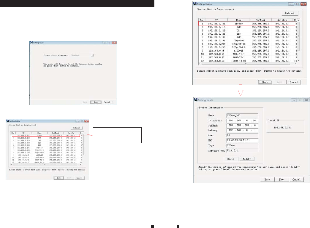
3)Press "Next" button, pop-up as below interface. Click “Refresh” button and online devices
on LAN will be shown on the list.
Double click one to
access the device.
4)Select a device from the list, and press “Next” button to modify the setting, pop-up as below
interface. 5)Options “IP Address”, “Sub Mask” and “Gate way” can be modified. Click “Modify” button,
pop-up as below interface. Input the device’s right account and password (default account
of administrator is “Admin” and default password of administrator is “888888”).
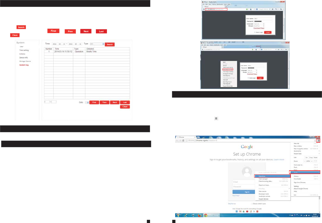
5.5 System Login
1)Open the web browser, enter the IP address of the device(such as ,
which can be searched by the program “HiCamSearcher_v1.1.exe”.
“http://xxx.xxx.xxx.xxx”)
Note: If the device is connected to the WAN, the IP address should be a public IP address.
The system will automatically enter the GUI as follows.
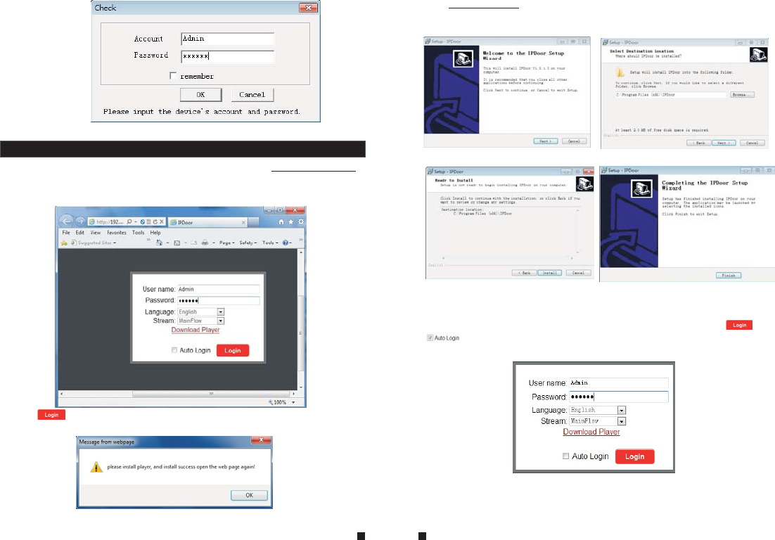
2) Click “ ”, if users access the device on the PC for the first time, it will pop up a window as
below, click “ok” and install player on the PC according to the following method.
Click “ Download Player ” and download the file “IPDoor.zip” to the PC. Open the zip file to
run the file “IPDoor.exe” and it will install outdoor device’s OCX on the PC (according to the
method as following figures).
3)After installing player on the PC, input the authorized user name and password, the default
user name is “Admin” and the default password is “888888”. Select language “English” or
“Chinese”, choose network stream “Main Flow” or “Minor Flow”, and then click “ ”.
“ ” indicates that it will enter into “Home” interface automatically when the device will
be connected to the web browser again on the same PC.
6)Click “OK” to confirm device parameters configuration.
23 24
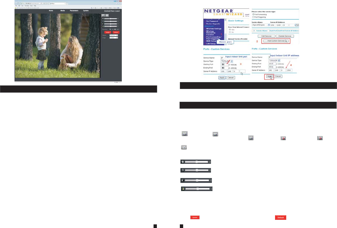
4)After login, it will enter into “Home” interface of the live view as follows.
5.6 Port Forwarding
If visit IP outdoor camera via Internet Explorer browser from WAN, you must do port forwarding
on the router. Port Forwarding is used to transfer information from your router directly to your
computer or outdoor device through Ports. What is a Port? Ports are openings through your
computer that allow data in you computer/outdoor device. The World Wide Web for example
uses Port 80. Anytime you go to a website, that goes over that specific port. The reason we
need to forward certain ports for your outdoor camera is so that you can view your cameras
over the Web(internet).Take Netgear router for example.
A few things that you need to find out about your Internet Connection:
* Do you have a Static IP or Dynamic IP? To find this out, contact your Internet Service Provider
and they should be able to tell you.
* If you have a Dynamic IP or PPPoE ADSL, you will need to set up an Account on DDNS
(www.dyndns.org or www.3322.org). That way when your IP changes, you can connect to the
same Hostname (ex: my.dyndns.org) everytime you connect. In other words, it makes your
Dynamic IP a static host address. This is very important if you want to connect to your outdoor
device remotely.
* Find out what equipment you are using from the Internet Service Provider. If it is a modem,
then you should be fine just configuring your router that's connected to it. Make sure to get the
username and passwords for any router you may have. If you can not log in to the router, you
will not be able to complete this setup. You may have to contact your Internet Service Provider
for this information.
Take Netgear router for example.
Operation Steps:
1) After login the interface of the router, choose “Port Forwarding”;
2) Choose “Add custom Service”;
3) Input IP outdoor camera ports, including http port 80 and mobile port 20510;
4)Input IP address of the outdoor device, click “Apply”(the HTTP port, the mobile port and IP
address should be the same as the following figure which set by your own).
Note: Different router has different settings for port forwarding; please kindly follow your
router guide to do the port-forwarding.
After the port-forwarding is done, you could view the IP outdoor camera from WAN now.
5.7 Function Settings
Options in the main interface include “Home”, “Media”, “Parameters” and “System”. Click any
option to access it.
5.7.1 Home
Click “Home” to enter the window for live video as follows, it includes video window, control
buttons and Image Settings.
Video window: Double click the real-time video then it will display video full-screen. Double
click it again then it will recovery default window.
Control buttons:
Record: Click “ Record” button, which could record the video with audio and store it at the
present path. When recording, the button “ ’’ will change to ‘‘ ’’. Click the button “ ” again,
and then the record stops.
Capture: Click the capture button, which could take photos for the current video and store the
image at the present path.
Image Settings:
: Adjust hue of image. Values can be set from 0~100.By default, the value is
set at 50.
: Adjust brightness of image. Values can be set from 0~100.By default, the value
is set at 50.
: Adjust contrast of image. Values can be set from 0~100.By default, the value is
set at 50.
: Adjust saturation of image. Values can be set from 0~100.By default, the value
is set at 50.
Powerfreq (Power Line Frequency): Options include 50HZ and 60HZ. If the monitoring site adopting
lighting elimination, user should set a corresponding frequency. If the two frequencies are different,
the image will flick. There are two frequencies on the world, one is 50HZ, and the other is 60HZ. In
China, adopt 50HZ.
Click “ ” to refresh the settings of the Image, and click “ ” to restore the parameters of
the image to the default settings.
25 26
IPDoor 2014-04-25 11:20:08
Stream: Set up network stream, including main flow and minor flow.
Image: Set up the size of view image. Options include Fit size and Src size.
5.7.2 Media
Click “Media” to enter the media parameter setting menu. This interface includes settings for
Video and OSD.
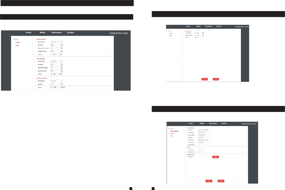
Click “Media—Video” to access the interface as follows. And user can set up parameters of main
stream, sub stream and mobile stream.
A. Video—Main Stream and Sub Stream
1)Resolution: For the resolution of main stream, there is only 720P(1280*720). And for the
resolution of sub stream, there is only VGA (640*360). The bigger the resolution is, the clearer
the image will be. On the other hand the bit rate is bigger and takes more bandwidth.
2)Bit Rate: User can choose a certain bit rate, generally speaking, the bigger the bit rate is,
the clearer the image will be. Please choose the suitable bit rate according to your bandwidth.
If you select a big bit rate, while the bandwidth is worse, it will cause the video stream can't be
transferred smoothly, the video quality will be not perfect too. The default bit rate value of main
stream is 2048kbps. And the default bit rate value of sub stream is 1024kbps.
3)Maximum Frame: User can choose a certain frame rate, when the bandwidth is limited,
suggest reducing the value. Generally, the video is fluency if the value is more 15 frames.
Default value is 30 frames for NTSC norm and is 25 frames for PAL norm.
4)Bit Rate Type: There are three modes for bit rate control, CBR, VBR and FixQp. If user
choose CBR mode, the video encoder will encode according to the bit rate you have selected.
If user choose VBR mode, the video encoder will consider to the image quality and encode
according to the bit rated have been selected, but not strictly according to this bit rate. Suggest
VBR mode.
5)Audio: Options include “On” and “Off”.----(Optional)
B. Video—Mobile Stream
1)Resolution:The resolution of mobile stream is QVGA (320*180).
2)Quality: The image quality of the outdoor camera for remote access viewing via mobile phone.
And there are five options: “Very High”, “High”, “Normal”, “Low” and “Very Low”. The better the
5.7.2.1 Media--Video
image quality is, the bigger the bit rate and the frame rate of the outdoor camera are. Please
choose the suitable quality according to your bandwidth.
C. Video Norm
From this field, select the system output type for outdoor camera, i.e. PAL or NTSC.
Note: The device will restart automatically if the outdoor camera output type is changed.
Click “Media—OSD” to access the interface as follows. OSD options include “Time Stamp”,
“Device Name” and “Name”.
1)Time Stamp: From this field, users can decide time stamp will be shown on the home page
for live viewing as the OSD (On-Screen Display) string wether or not.
2)Device Name: User can add the equipment's name on the home page for live viewing
through this setting.
3)Name: Users can modify the name of the outdoor device. Note that the name of the device
must not exceed twelve arabic numbers, letters or twelve Chinese characters.
5.7.3 Parameters
Click “Media” to enter the parameters setting menu. This interface includes settings for
Network (Basic Settings, DDNS, and Wifi-optional) and Event (Record).
5.7.2.2 Media--OSD
27 28
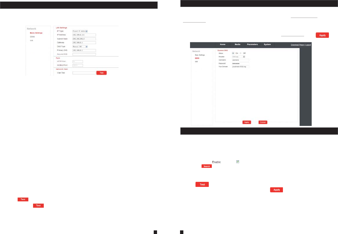
A. LAN Settings
[IP Type]: There are two options: “Fixed IP Address” and “dynamic IP Address”.
After selecting an Internet connection setting - such as fixed IP address (static) or dynamic IP
address (DHCP) – and allocating a port, users can access the IP outdoor camera remotely via
the Internet.
1)If fixed IP address has been selected, it is necessary to set up an IP address, a subnet mask
and a gateway.
[IP Address]: Enter the IP address in this field.
[Subnet Mask]: Input numbers for the subnet mask.
[Gateway]: Enter numbers for the default gateway.
[DNS Type]: Options include “Manual DNS” and “From DHCP Server”. If users select “Manual
DNS”, they have to input numbers for primary DNS and second DNS manually.
2)If DHCP is selected, the server will allocate an outdoor camera IP address automatically.
NOTE: Save the IP address when selecting DHCP and the outdoor camera will automatically
connect with the server. It will allocate an IP address when the connection is stable, and this
address will be displayed on the interface.
B. HTTP
[HTTP Port]: The IP address identity one outdoor device in the network, you can run several
programs on this equipment, and every program will transfer the data through some port, in fact
data is transferred from one port to another. The port setting of this page is asking user choose
which port to transfer the data for the web server. Doing port mapping, need to maintain
consistent with the port (equipment factory default port is 80).Sets up a Web browser port via
HTTP. The default port number is “80”.
[Mobile port]: Mobile monitoring port. And default value is 20510.
C. Network Test
[Wan Test]: In this field, users can fill in the IP address or DDNS address which they set up,
and click “ ” to test the network traffic is normal or not. If all the network parameters are
set correctly, click “ ” and “Test Success!” will be shown. Otherwise “Test Failure!” will
be shown.
5.7.3.1 Network--Basic Settings
Click “Parameters—Network—Basic Settings” to enter the LAN Settings interface. Default IP
type is “dynamic IP Address”. The user can set up device network parameters through the
operation “Quick Setting Guide”, user can change it according to your network environment.
5.7.3.2 Network--DDNS
Click “Parameters-Network-DDNS”to enter the DDNS setting interface. DDNS setup as follows.
User can use third part DDNS, first user must have a domain name; www.dyndns.org or
www.3322.org is recommended. Please remember the username, password and domain name.
Then enable DDNS, for example, select the DDNS Provider as “3322.org”. If your domain name
is “test.f3322.org”, please enter “test.f3322.org” in the option “Your Domain”, the “Username” and
“Password” is the username and password that applied in the www.3322.org. Click “ ” to
save. Then you can access the device by domain name.
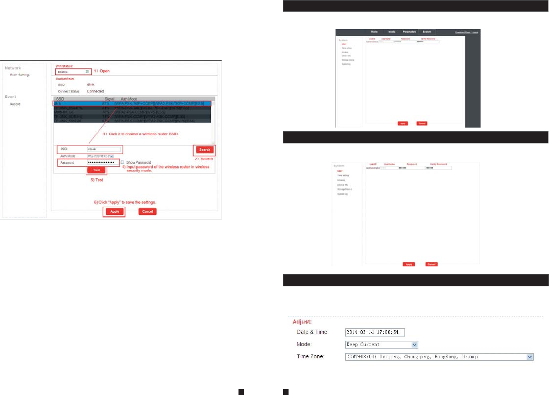
5.7.3.3 Network--Wifi(Optional, please take actual machine as quasi)
For the outdoor device with WIFI function, users can visit the device remotely by the following
methods: through network cable connection or through wireless connection. If through wireless
connection, please use the network cable to connect the device into LAN before doing settings
of wireless connection. Then click “Parameters—Network—WiFi” to enter the Wifi Setting
interface, and according to the below 1-6 steps to do the settings.
1) Open wireless, “ ” indicates WIFI status to be enabled.
2) Click the “ ” button to search the current wireless routers, and all the wireless routers
will appear on the Current Hot Point list.
3) Choose one effective router, click it to choose router SSID.
4) Input correct password of the wireless router in wireless security mode.
5) Click “ ” to check the wireless network is connected successfully or not.
6)When the wireless is connected successfully, click “ ” to save the settings, the device
will be reboot automatically, take away the Ethernet cable, then the wireless network will work
perfectly.
Note: 1. When adjust WIFI status, the device will be reboot after saving the setting.
2. When enable WIFI status, the device will be reboot automatically if plug or unplug the
network cable connected to the outdoor device.
3. Through Wifi connection, the “Network Type” on the Network Basic Setting suggested
to be set as “DHCP”. When configure the parameters about WIFI, user can view the outdoor
device can be allocated IP address whether or not through the search tool “HiCamSearcher”.
29 30
5.7.4 System
Click “System” to enter the parameters setting menu. This interface includes settings for User,
Time setting, Initialize, Device info, Storage Device and System Logo.
31 32
If not, user must set up parameters about Wifi again.
4. When the equipment connected to the Internet, and also enable the WIFI, when
activated, the equipment will be the first to choose Ethernet cable connection mode, if
can't connect, then choose WIFI connection. WIFI connection of the ports to use are
consistent with cable connection of the ports to use.
5.7.4.1 System-User
Click “System—user” to access user setting menu, the default username and password of
administrator is “Admin” and “888888”.
5.7.4.2 System-Time Setting
Click “System—Time setting” to access time setting menu. There are four types of time mode:
keep current, manual, Sync with computer time and Sync with NTP.
1) “Keep Current” means the system time won't be changed.
2) “Manual” means adjust time manually. Users need to enter date & time and time zone
manually.
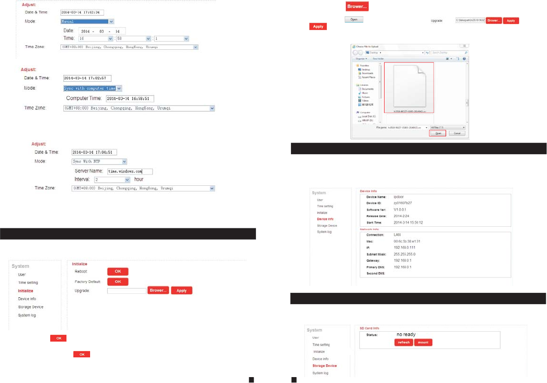
3) “Sync with computer time” means through this apply to sync IP outdoor camera system
time to local PC time.
4) “Sync with NTP” will choose a same time zone with the NTP server automatically. Server
name is the NTP server host, and the interval of refresh time includes 1 hour, 2 hours, 12 hours
and 24hous. Save all parameters, then it will update as a network clock.
5.7.4.3 System-Initialize
Click “System—Initialize” to access initialize setting menu. This interface includes settings for
Reboot, Factory Default and Upgrade.
1) Reboot: Click “ ”, it will pop-up a message window “the device will be rebooted. Are
you sure?”, and click “OK” to restart the equipment.
2) Factory Default: Click “ ” , it will pop-up a message window “Set up data will be
initialized. Are you sure?” Click “OK” to restore all the parameters to the default settings
except IP address.
3) Upgrade: Click “ ” to select the firmware file for upgrading, for example, the
firmware file such as “hi3518-96223-V1003-20140421.ov” is on the desktop. First choose the
firmware file, click “ ”, and it will be shown as “ ”,then
click “ ” to upgrade the equipment whether or not. After the upgrading, the equipment
will restart.
Note: During upgrading, please don’t power off the outdoor device.
33 34
5.7.4.4 System-Device Info
Click “System—Device Info” to enter the “Device Information” menu as follows. The information
included accessible through this interface includes: Device Info (Device Name, Device ID,
Software Version, Release date and Start Time), Network Info (Connection, Mac, IP, Subnet
Mask, Gateway, Primary DNS and Second DNS).
5.7.4.5 System-Storage Device
Click “System—Storage Device” to enter the interface of SD card information as follows.
The option “status” for the models without SD card will show “no ready”.
5) “Delay push(s)”: From this field, user can adjust delay duration time of alarm push for visitor
calling, and values can be set from 0 to 60s. For example, to select 5s, if visitor presses the call
button on the outdoor camera, the message will be pushed onto the master’s phone after 5
seconds.
5.7.5 Logout
Click “Logout” to log out of the system.
5.7.4.6 System-System Log
Click “System—System Log” to enter the “system log” menu as follows.
At the top of the “Log Search” page are the following filters to facilitate locating the desired file(s):
[Time]: Set the starting time and the ending time of the log being searched for.
[Type]: Choose from the following options: “All”, “Alarm” and “Operation”.
Click the “ ” button after setting the log time and type, and the system will display the
selected log in the list. Click “ ”, “ ”, “ ”, “ ” to navigate pages, and
click “ ” to delete all the log lists.
36
1.First, install Firefox on Windows(This document will use Firefox 28.0 as an example).
2. After installing Firefox, please search for the “IE Tab” add-on for Firefox, which can be
downloaded from Firefox browser.
3. Open Firefox, click “Tools-->Add-ons” to enter into the interface of “Get Add-ons”, and search
for “IE Tab”, all the IE tabs will be shown on the list for “Available Add-ons”. Choose one and install
it, this document will use IE Tab 2(FF 3.6+)5.12.12.1 for example.
4. After installing the IE Tab, user need restart Firefox browser.
5. Open Firefox and enter the outdoor device IP address in the address field. Right-click at blank,
select “View Page in IE tab”. The outdoor device can now be connected successfully.
Appendix 1. Accessing the IP outdoor camera via Mozilla Firefox
1.First, installing Google Chrome Browser on Windows(this manual will use Chrome version
34.0.1847.116 m as an example).
2. After installing Google Chrome, search for the “IE Tab” add-on for Chrome, which can be
downloaded from the Chrome Web Store.
3. Opening Chrome, click “ Customize and control Google Chrome->Tools->Extensions->
browser the gallery” to enter the “Chrome Web Store” interface to search for “IE Tab”, and results
for IE tab in Extensions will appear on the right side. Choose one to install it and it’s free for
installation(Shown as below).
Appendix 2. Accessing the IP outdoor camera via google Chrome
35
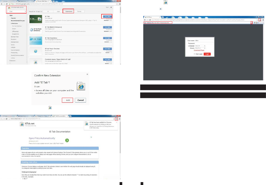
4. During installation, the following figure will appear, click “Add” to confirm to install “IE Tab”
add-on.
5. After complete installation, the icon “ ” will appear on the right top of the browser interface
(Shown on the red frame as below), and it means that IE Tab has been added to Chrome browser.
37 38
6. Click the icon “ ” on the right top of the address field to display the Chrome web page in an
IE-based page, and fill in the IP address of the outdoor device on the IE-based address bar, then
click the icon “ ” to access the remote device, fill in the correct user name and password to log in.
Default user name and password are “Admin” and “888888".(shown on the red frames as below)
Appendix 3 How to ensure reliable remote viewing of the IP
outdoor camera through IE browser on Win 7/Win 8 64bit OS
1. Run 32bit IE on Windows OS (64bit)
Note: On a 64-bit version of a Windows operating system, there are two versions of the
Internet Explorer files:
* The 64-bit version is “C:\Program Files\ Internet Explorer \iexplore.exe”.
* The 32-bit version is “C:\Program Files(x86) \ Internet Explorer \iexplore.exe”.
* Please run the 32-bit version “C:\Program Files(x86) \Internet Explorer \iexplore.exe”.
2. Run Internet Explorer as the Administrator
1) Open folder path “C:\Program Files(x86) \Internet Explorer”.
2) Right click the Internet Explorer icon and choose "Run as Administrator".
3) Click "Continue" in the User Account Control window to grant administrator access to
Internet Explorer.
3. Download ActiveX control after type in IP address & Port
1) Open an Internet Explorer browser window to make changes to your current ActiveX controls.
Click the “Tools” link located at the top of the menu bar. A drop down window will appear with
several more options to choose from. Each option will let you change some of the default
settings already programmed into Internet Explorer.
2) Click the “Internet Options” link located at the end of the list. When the pop-up window
appears, select the “Security” tab to access the ActiveX controls. There are several zones with
multiple security settings. Each zone has preset settings built into it. You can change the
settings to fit your current needs. If for some reason you're not satisfied with these changes,
click the “Reset All Zones to Default Level” to change them back. To allow ActiveX controls to
run, click the “Internet” zone. The icon that identifies this zone looks like Earth.

39 40
3) Change the security level for the “Internet” zone from the default “Medium-high” zone to
“Medium". Slide the bar up and down between the different security zones. The “Medium”
Internet zone will allow a lower security environment for your web browsing. To go even
further with enabling the ActiveX controls, click the “Custom Level” button. Under the
“Settings” menu, look for the “ActiveX Controls and Plug-ins” options. Normally, these
settings are disabled to prevent a security risk to your computer system.
4) Allow the ActiveX controls to automatically run by changing the settings from “Disable” to
“Enable”. This can be done by clicking the “Enable” button next to “Allow Previously Unused
ActiveX Controls to Run without Prompt”. After making these changes to your Internet
Explorer browser, you won't be constantly prompted to enable the ActiveX controls. They'll
automatically be allowed without prompting you to manually do so. The changes made in
these settings will not take full effect until you close and restart the Internet Explorer browser
window.
4. Fix site display problems with Compatibility View
Sometimes a website you're visiting doesn't look like you expect it to. Images might not show
up, menus might be out of place, and text boxes could be jumbled together. This can be caused
by a compatibility problem between Internet Explorer and the site you're on. When a site is
incompatible with Internet Explorer, you'll see the Compatibility View button in the Address bar.
You can only turn on Compatibility View in Internet Explorer for the desktop.
A. To turn on Compatibility View
1) See if the Compatibility View button appears in the Address bar. (If you don't see the
button, there's no need to turn on Compatibility View.)
2) Tap or click the Compatibility View button to display the site in Compatibility View.
Once you turn on Compatibility View, Internet Explorer will automatically show that site in
Compatibility View each time you visit. You can turn it off by tapping or clicking the button
again. Or, you can clear the entire list of sites using Compatibility View by deleting your
browsing history.
B. To clear the list of Compatibility View sites
Not all website display problems are caused by browser incompatibility. Interrupted Internet
connections, heavy traffic, or problems with the website can also affect how a page is displayed.
If you're having other problems on a site, such as playing videos, read Video won't play in
Internet Explorer.
The Compatibility List is frequently updated, and Internet Explorer automatically downloads
these update. This list includes sites that might've been designed for older or other browsers,
sites that use Adobe Flash Player, and other settings that help give you a better browsing
experience. If you don't want these updates, you can turn off Compatibility List Updates at
any time.
C. To turn off Compatibility List Updates
1) Open Internet Explorer in the desktop.
2) Press the Alt key to display the Menu bar (or press and hold the Address bar and then select
Menu bar).
3)Tap or click Tools, and then tap or click Compatibility View settings.
4) Clear the Download updated compatibility lists from Microsoft check box, and then tap or
click Close.
D. To change Compatibility View settings
1) Open Internet Explorer in the desktop.
2) Press the Alt key to display the Menu bar (or press and hold the Address bar and then select
Menu bar).
3) Tap or click Tools, and then tap or click Compatibility View settings.
Statement
* If there is any doubt or disputable regarding information in this manual, you can call our company for
clarification.
* There maybe some differences between the descriptions provided here and the actual devices, as our
products are constantly developing and upgrading. We apologize if this manual does not contain all of the
latest updates.Thanks.
FCC Notice
This device complies with Part 15 of the FCC Rules. Operation is
subject to the following two conditions:
(1) This device may not cause harmful interference, and (2) this device must accept any
interference received, including interference that may cause undesired operation.
NOTE 1: This equipment has been tested and found to comply with the limits for a Class B digital
device, pursuant to part 15 of the FCC Rules. These limits are designed to provide reasonable
protection against harmful interference in a residential installation. This equipment generates, uses
and can radiate radio frequency energy and, if not installed and used in accordance with the
instructions, may cause harmful interference to radio communications. However, there is no
guarantee that interference will not occur in a particular installation. If this equipment does cause
harmful interference to radio or television reception, which can be determined by turning the
equipment off and on, the user is encouraged to try to correct the interference by one or more of
the following measures:
- Reorient or relocate the receiving antenna.
- Increase the separation between the equipment and receiver.
-Connect the equipment into an outlet on a circuit different from that to which the receiver is
connected.
-Consult the dealer or an experienced radio/TV technician for help.
NOTE 2: Any changes or modifications to this unit not expressly approved by the party
responsible for compliance could void the user's authority to operate the equipment.