LB Technology 96330AW-CEM IP VIDEO DOOR PHONE User Manual
LB Technology Co., Ltd. IP VIDEO DOOR PHONE
UserManual.wiki
>
LB Technology
>
96330AW CEM User Manual
User Manual
Navigation menu
Upload a User Manual
Namespaces
Wiki Guide
HTML
PDF
Info
Views
User Manual
Discussion / Help
Navigation
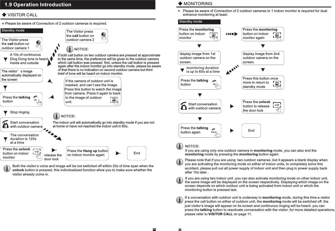
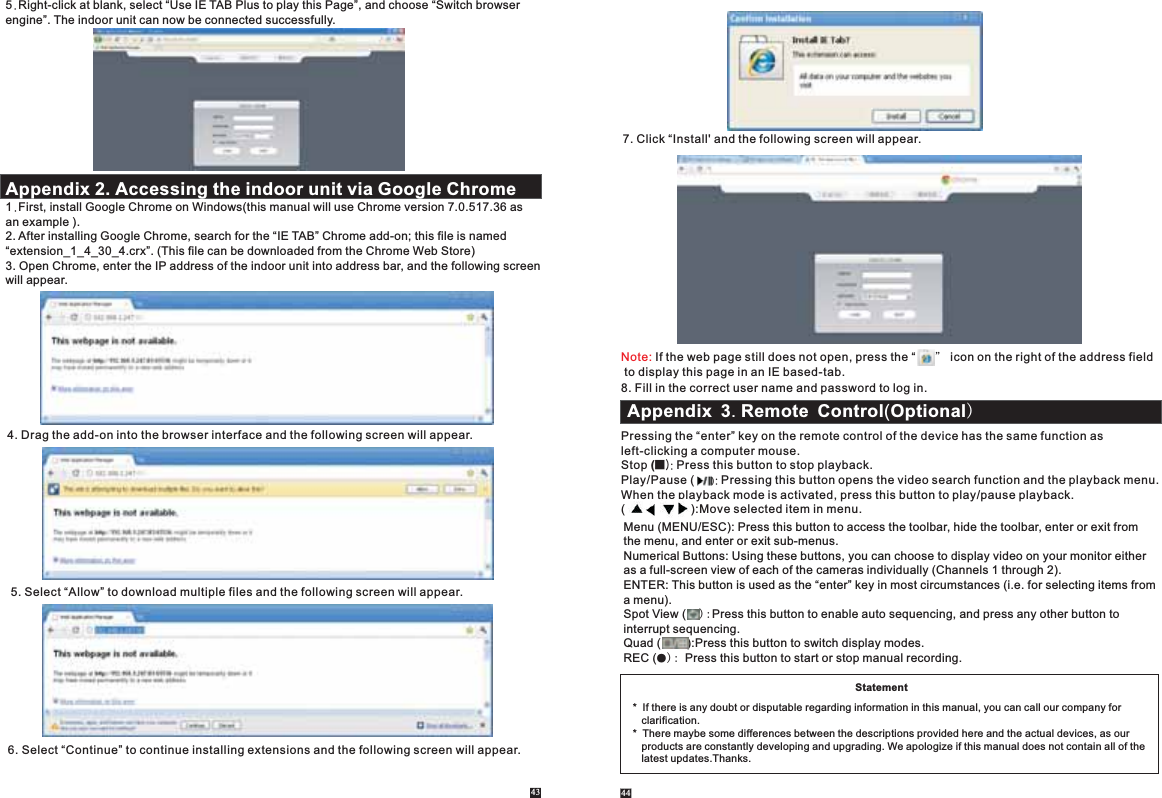
![15 16Note: 1. If there is no “ ” button in the sub-menu, in order to for changes to sub-menu settings to take effect, it is necessary to return to the “save” menu to click “ ”. Changes to the sub-menusettings will not be saved if you do not click “ ” and exit the sub-menu immediately afterward. 2. If there is a “ ” button in the sub-menu, users need to click the “ ” button to save parameters in the current window.3.A special feature of this device is that an explanation of each menu item will be displayed automatically when the cursor is moved over it.There are two ways of recording live video/audio feed from your cameras: manual recording and scheduled recording.If scheduled recording is in conflict with manual recording, the manual recording will be processed first until stopped. For a detailed description of scheduled recording, see In order to manually record a video/audio feed, click the “ ” button from the “Tools” menu. Clicking “ ” again will stop the recording process.To start video playback, first move the cursor to “ ” (the icon will be highlighted when selected) and left-click it to enter the settings menu. And left-clicking the “x” button will exit the current window, or move the cursor to the ““x” button and left-click it to exit. Section 2.4.3 Record Scheduling. Input the date and time, click “ ” and the recording status on that date will be displayed. Thecalendar on the above figure will show all the recordings in a given month. A background on the calendar indicates that there was recording on the day. Click any date in this frame to search by the recording files of that day, and the search results will be shown in the file frame.On the file list, “Channel” shows which channel the file was recorded under, “Time” shows the recording time, and “Size” is the size of this file (listed in MB). An orange list indicates this recording file is a motion detection recording file, and a black list indicates this file is a normal recording file. 2.3.2 Manual Recording2.3.3 Video PlaybackMove the cursor up or down to select the files, left-click to enter the playback menu. It will play thevideo from a single channel in full-screen view. When the selected files finish, the screen will return to the file list menu.Clicking “ ” button to enter into the first page, clicking “ ” button to previous, clicking “ ” buttonto the next page, and clicking “ ” to the last page. 2. When the selected files finish, the screen will return to the file list menu.In playback mode, users can view the playback control panel as well as the date and time of the file being played. Playback ControlThe following are the functions of and options for the items in the playback control panel: PlayPauseMinimize the control panel.Exit from playback and return to the formermenu.In order to modify or adjust the system configuration, it is necessary to enter the “Setup” menu; to do this, click the “Setup” icon ( ) in the “Tools” Menu.“Playback”, “Network”, “Scheduling”, “Alarm”, “Maintenance”, “User”, “Default” and “Information”. The following are detailed descriptions of these settings.2.4.1 SystemMove the cursor to the “System” icon and left-click to enter the “System” menu. System setup includes: “Basic configure” and “Time”.2.4 Menu Options 1. After moving the cursor up or down and selecting the files, left-click to enter the playback menu.It will play the video from a single channel in full-screen view. Note:2.3.4 Ring SettingSingle Click “ ” on the tool bar menu to enter the “Ring setting”menu.[Ring]: Click the icon “ ” on the right side of the option to adjust the ring type.[Volume]: To set up the volume of the ring,values can be set from 15 to 30.[Ring time]:To set up the ring time of the ring, values can be set from 5 seconds to 30 seconds.[Unlock time]: Options can be set up from 1 second to 10 seconds.After clicking the “Setup” icon, a dialog box with settings for all of the systems and options available for the device will appear. The settings are divided into nine subsections: “System”,](https://usermanual.wiki/LB-Technology/96330AW-CEM/User-Guide-2515214-Page-9.png)
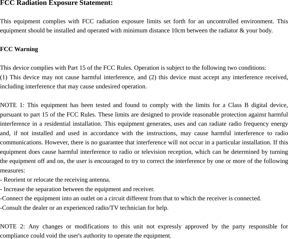
![Basic configure includes: “Language”, “Standard”, “Color Setup” and “Video margin”.[Standard]: From this field, select the system output type that is consistent with camera input,i.e. PAL or NTSC.[Language]: Use this field to change the language of the device menu text and the on-screen display.[Color Setup] location where the camera is installed.Click the vertical bar on the slide bar and drag the cursor to the left or right along the slide bar to set color attributes. Once the color attributes have been set, click “ ” to save the settings. [Video Margin]Click “ ” to enter the “Video Margin” menu, the entire video screen can be moved up, down, to the left, and to the right using this option.17Click “ ” to enter the “Color Setup” menu. From this menu, the video color attributes can be adjusted for the best image quality. By default, the values are set at31, as this is the median value. Make adjustments to the chroma, brightness, contrast, and/or saturation as appropriate depending on the actual conditions at the [Date Format]: Left-click to switch the date format, include YY/MM/DD, MM/DD/YY and DD/MM/YY.[Date]: Left-click to switch the numerical keypad, and set the date using the numerical keypad.[Time Format]: Left-click to switch the time format from a 12-hour clock to a 24-hour clock and vice versa.[Time]: Left-click to switch the numerical keypad, and set the system time using the numericalkeypad.2.4.1.1 System-Basic2.4.1.2 System-TimeMove the cursor to the “Network” icon and left-click to enter the “Network” menu. Network setupincludes: “Basic Setup”, “Port” and “Advanced”.2.4.2.1 Network-Basic[Network Link]: There are three options: “Static” and “DHCP”.After selecting an Internet connection setting - such as static or DHCP – and allocating a port, users can access the device remotely via the Internet. 1)If static allocation has been selected, it is necessary to set up an IP address, a subnet mask, agateway, and a Web port. [IP Address]: Enter the IP address in this field.[Subnet Mask]:Input numbers for the subnet mask.[Gateway]: Enter numbers for the default gateway.[DNS Address]: Input numbers for the subnet mask in this field.2)If DHCP is selected, the server will allocate an indoor unit IP address automatically. Save the IP address when selecting DHCP and the indoor unit will automatically connect with the server. It will allocate an IP address when the connection is stable, and this address will be displayed on the interface.NOTE:2.4.2.2 Network-Port2.4.2 Network18](https://usermanual.wiki/LB-Technology/96330AW-CEM/User-Guide-2515214-Page-10.png)
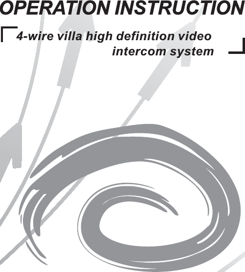
![[Media Port]: Port for the private protocol of the device and computer; the default is “9000”. If this port is being used by other server, use another free port for the device.[Web Port]: Sets up a Web browser port via HTTP. The default port number is “8090”, but thespecific number is model-dependent. If Administrator changes the Web port, for example, “8088”, the port number should be added after the IP address, i.e. http://192.168.15.145:8088should be entered as the IP address of the Web browser.[Setup Port]: It's used to control the device. The default number is “8000”. User can specify a different port number.In advanced menu, user can set up DDNS, Wifi, UPNP, Mobile phone, Sub Stream andIP firewall.“ ” indicates the selected option is enable. Click “ ” to enter into the next page,and click “ ” to the previous. User should enable the relevant function with “ “ before setup.Note:A. DDNS“ ”indicates DDNS is enabled. Move the cursor to “DDNS” (the tab will be highlighted when selected) and single-click to enter the DDNS setup menu.[Server]: There are three options: “3322”, “dyndns” and “easterndns”.[Host Name]: In this field, enter the name of the host server.[User Name]: In this field, enter the username.[Password]: In this field, enter the password.B. Wifi (Optional)For the indoor unit with WIFI function, users can visit the device remotely by the following methods: through network cable connection or through wireless connection. If through wireless connection, please setup the parameters about Wifi manually. indicates Wifi is enabled.Move the cursor to “Wifi” (the tab will be highlighted when selected) and single-click to enter the Wifi setup menu. “ ”Note: Through Wifi connection, the “Network Type” on the Network Basic interface suggested to be set as “DHCP”. When configure the parameters about WIFi, user can enter the network basic interface to view the indoor unit can be allocated IP address whether or not. If not, user must set up parameters about Wifi again.19 20[SSID]: Input the effective wireless router SSID.[Password]: If the password of the wireless router is enabled, the option should be adjusted to “ ”.[AuthMode]: Options include “WPA-PSK” and “WPA2-PSK”.[EncrypType]: Options include “AES” and “TKIP”.[Key]: Input the password of the wireless router. C. UPNP“ ”indicates UPNP is enabled. D. Mobile PhoneMove the cursor over “Mobile Phone” (the tab will be highlighted when selected), and single-clickto enter the mobile settings menu. [Phone port]: Mobile monitoring port. In this field, enter the relevant mobile port. The range for server ports is between “1024” and “65535”. The default is “10510”.[Push time(s)]: From this field, select push time for motion detection or visitor calling.[Push]: “ ” indicates the push function is to be enabled. E. Sub StreamMove the cursor over “Sub Stream” (the tab will be highlighted when selected), and single-clickto enter the Sub steam menu. 2.4.2.3 Network - Advanced](https://usermanual.wiki/LB-Technology/96330AW-CEM/User-Guide-2515214-Page-11.png)
![[Channel]: After clicking the “Channel” tab, users can modify the settings of the camera connected to the selected channel. Users can modify the parameters of each channel independently.[Frame rate]: For the PAL video output format, options include 5-25 frames. For the NTSC video output format, options include 5-30 frames.[Bit rate]: There are 5 options: 64K, 128K, 192K, 256K and 384K. [Bit rate control]: There are two modes for bit rate control: VBR and CBR. If users choose CBR mode, the video encoder will encode according to the bit rate you have selected. If userschoose VBR mode, the video encoder will consider to the image quality and encode accordingto the bit rated have been selected, but not strictly according to this bit rate. Suggest VBR mode.F. IP FirewallMove the cursor over “IP Firewall” (the icon will be highlighted when selected), and single-clickto enter the IP Firewall menu. The options for IP access settings are: “disable”, “Black list” and “White list”. 2.4.3 Record SchedulingClick Setup”—“Scheduling”(the tab will be highlighted when selected) and single-click to enter the “Record Scheduling” menu.[Channel]: Users can select channel 3 or channel 4.There are three modes for recording: “MD”, “Normal”, “None”. Different colors are used to identify the different recording modes: Orange refers to “MD record”, green refers to “normal record”, gray refers to “no record”.To set up weekly schedules, click on the box of the recording status to be used (Alarm, Normal,or No record) and then click on each box in the schedule timeline that this recording status is to be applied to. See the “Scheduling” screenshot in the preceding figure. Each gray block represents one hour on a 24-hour clock, i.e. the first block(next to each day of the week) represents the hour from midnight-01:00 AM and the last block (below the “23” on the right hand side of the screen) represents the hour from 11:00 PM-midnight. After setting up the record schedule, click the “ ” button at the bottom of the screen to save it.Alternatively, left-click and drag the frames of the boxes in the schedule timeline where you want to. Another way to set up schedules is to create a schedule for one day of the week, and then use the “Copy from” and “to” dropdown menus and “ ” copy button settings to apply the setting from one day to another day or a series of up to all seven days of the week. To do this, first create a schedule for one day. Then, from the “Copy from” dropdown menu, select the firstday of the week that the schedule should apply to. Next, from the “to” dropdown menu, select the last day of the week that the schedule should apply to, and click “ ” copy button. For example, to set a schedule where the device uses MD recording from 2:00 AM until 1:00 PM, and normal recording from 1:00 PM until 10:00 PM on Tuesdays, Wednesdays, Thursdays, and 21 22Fridays, the process would be as follows: 1. Click the orange box at the bottom of the screen to select “MD record.” Then, in the row of gray boxes next to the “TUE.” box, click all of boxes from the third box from the left to the box under the “12” at the top of the timeline(the box directly under the “12” should be selected) in order to select the hours between 2:00 AM and 1:00 PM. 2. Click the green box at the bottom of the screen to select “normal record.” Then click all of the boxes in the same row from the box immediately to the right of the box under the “12” at the top of the timeline to the third box from the right to select the hours from 1:00 PM-10:00 PM. 3. The preceding steps set a schedule for Tuesday, which can now be copied to Wednesday, Thursday, and Friday. To copy it, from the “FROM” field, first select “Tues.”4. In the “To” field, select “Fri.” and then click “ ” copy button.5. To save this schedule, click the “ ” button at the bottom of the screen. Regardless of whether the schedule is set for each day individually or by copying one schedule to multiple days of the week, it is necessary activate it by clicking the “ ” button. Withoutclicking the “ ” the schedule will not take effect.2.4.4 AlarmClick “Setup”—“Alarm”(the tab will be highlighted when selected) and single-click to enter the “Alarm” menu. And the dialog window where Sensitivity, MD Area, Enable Switch and record settings can be set will appear.[Channel]: In this field, select the channel to be set up.[Sensitivity]: Each channel has a specific sensitivity setting; there are eight levels, with “1” being the highest level of sensitivity; left-clicking to adjust the level.[MD Area]: Sometimes, it is necessary to have someregions in the camera's coverage area enabled with the motion detection feature, while other regions in the same coverage area do not require this functionality. This may be handy when, for example, the camera covers the road and an adjoining area. While it would be useful to have the motion detection enabled on the area near the entrance to a building, it would most likely not be helpful to see it triggered every time a car or truck passes by on the nearby road. Each channel has a specific regional motion detecting setting.Move the cursor to “ ” and then single-click.When viewing the selected channel's coverage area using the MD Area option, the blue area is where motion detection is activated, and transparentblock is the area where motion detection is not activated.Left-click and drag the frame to set up the region for motion detection.[MD Enable]: Each channel has a corresponding channel switch. “ ” indicates that the motion detection alarm of the selected channel is enabled. [Record]: “ ” indicates that the selected channel will record if it has been triggered by motion.Note: To select the option, please make sure that a SD card has been already inserted into the video data can be stored onto the SD card normally. 2.4.5 MaintenanceClick “Setup”—“Alarm”(the tab will be highlighted when selected) and single-click to enter the “System Maintenance” menu. Options include “SD Management” and “System Upgrade”.](https://usermanual.wiki/LB-Technology/96330AW-CEM/User-Guide-2515214-Page-12.png)
![2.4.5.1 SDTo enter the “System Maintenance”, select “SD” (see adjacent figure).[Size/Free]: This field indicates amount of space available and the amount of unused space available on the SD card.[Free Time]: Indicates remaining recording time on the SD card.[State]: There are three available statuses: “OK” and “No SD”.If a new SD card is used with the device for the first time, please format the SD card. [Format]: Move the cursor to select the device to be formatted, “ ” indicates the option of “format” is enabled, and click “ ” to begin formatting.[Auto overwrite]:Options Include “Disable and Auto”. If a user chooses “Disable”, the recording stops when the SD card is full. Once the SD card is full, it will not record again until “overwrite” is enabled. If a user chooses “Auto”, recording continues and overwrites previous recording when the SD card is full.2.4.5.2 UpgradeTo enter the “system Maintenance”, select “upgrade”(see adjacent figure).23 24Create a new root directory called “ivrupgrade” on a SD card, copy the update file to it, and then insert it into SD port of the device. Click “ ” to upgrade the firmware and it will display the process of the system upgrade.Note: The system upgrade will require at least two minutes; during this time, do not remove the SD card or turn the device disable. After completing the upgrade, the device will restart.2.4.6 UserClick “Setup”—“User”(the tab will be highlighted when selected) and single-click to enter the “User” menu. In this field, a password for accessing the device system can be changed.From this window, the Administrator can change the system's password. For security reasons, before a new password can be set, it is necessary to enter the original password. Click “ ” to save. 2.4.7 DefaultClick “Setup”—“Default”(the tab will be highlighted when selected) and single-click to enter the “Restore to default” menu. The system restores the default configuration status in the factory, and corresponding settingcan be resumed based on options on the menu. User can select “All” to restore all the settingsto the original factory settings. The options include: Time, Color and margin, Record schedule,User, Maintenance, Network, Network advanced and Alarm setup. Prompt: The port and language can't be resumed. 2.4.8 InformationClick “Setup”—“Information”(the tab will be highlighted when selected) and single-click to enter the “Device information” menu. The information included accessible through this interface includes: the device ID, the software version and the release date.](https://usermanual.wiki/LB-Technology/96330AW-CEM/User-Guide-2515214-Page-13.png)
![2.4.9 Save/ExitOn the “Configuration” menu, right-click or click “ ” to enter the “Save” menu. [Save]: Save all settings and exit the menu.[Exit]: Exit the menu without saving any changes.3. Web Browser OperationInstall the software through the Internet browser of OS to conveniently operate the networkfrom a remote location. This device supports C/S, B/S, and access in LAN and WAN. It also supports IP and domain name visiting.To ensure reliable remote viewing of IVR footage, it is highly recommended that users have either Windows XP, Windows 7 or Windows 8 installed on their computers, and that they use either Internet Explorer 6.0, Internet Explorer 7.0, Internet Explorer 8.0, Internet Explorer 9.0, Mozilla Firefox, or Google Chrome as their Internet browser. (In the appendix, there is an explanation of how to access the indoor unit using Firefox or Google Chrome.)Prior to setting up remote access, set the network security level by following the following instructions:(1) Open the Internet Explorer browser and click the “Tools” tab located in the bar at the top of the browser; from the drop-down menu, select “Internet Options”.(2) Click the “Security” tab in the dialogue box(3) Click “Custom level” (at the bottom of the dialogue box) to set the security level. .IMPORTANT! SOFTWARE RECOMMENDATIONS:25 263.1 Feature3.2 Network Security SettingSet the appropriate settings for the ActiveX controls and plug-ins. Find the following controls in the “Security Settings” box and select the “Enable” option for each of them. This is an extremely important step.* Automatic prompting for ActiveX controls. * Binary and script behaviors.* Initialize and script ActiveX controls not marked as safe for scripting.* Download signed ActiveX controls.* Download unsigned ActiveX controls.* Run ActiveX controls and plug-ins.* Script ActiveX controls safe for scripting.Prompt: Before setting up remote access, turn Disable the firewall and any anti-virus softwarecurrently running on the computer.Remote access to the IP video door phone is carried out over the Internet. In the local area network, the IP address of the client-side computer must be in the same network segment that the IP address of the IP video door phone. In the wide area network, the only requirement is that the two sides can visit the public network and connect to the Internet through the IP address or the dynamic domain name. The following will mainly focus on connecting and setting up the local area network.Step 1: Right-click on “Network Neighborhood” and click “Properties” in the menu to open the “Network Connections” menu. Alternatively, if the operating system being used does not have a “Network Neighborhood” icon, enter the Control Panel found in the “Start” menu; then, click “Network and Internet”, and select “Network and Sharing Center.” On the “Network and Sharing Center” page, there should be a “Network” section; in that section, there should be a “View Status” link next to a listing that reads “Connection: Local Area Connection.” Click the “View Status” link. A small “Local Area Connection Status” window will appear; at the bottom of this screen, click “Properties”, and if prompted to give permission to continue, click “Yes.”Step 2: Double-click to open “Local Area Connection” from the “Network Connections” menu.Step 3: Click “Properties” in the lower-left corner of the window(see preceding figure).Step 4: Double-click “Internet protocol (TCP/IP)” from the “Thisconnection uses the following items” list in the center of the window (see preceding figure). 3.3 Connection Settings](https://usermanual.wiki/LB-Technology/96330AW-CEM/User-Guide-2515214-Page-14.png)
![Step 5: Examine the IP address, subnet mask, and default gateway on the PC. Step 6: Set the corresponding IP address, subnet mask, and default gateway on the indoor unit(for detailed instructions, refer to ). If the subnet mask and default gateway on the indoor unit are the same as those of the computer, then the IP address is most likely in the same network segment. However, they must not be exactly the same as the ones on the indoor unit, as this will cause IP address conflicts. Taking the preceding figure as an example, the IP address should be: 192.168.1.X, where X cannot be 244 or 1 (including other IP addresses currently being used), and cannot exceed 255, as the subnet mask is 255.255.255.0, and the gateway is 192.168.1.1. Section 2.4.2 Network Setup3.4 Control Download and InstallationAfter the aforementioned settings have been adjusted and saved, open the Internet browser, enter (192.168.1.X is the set IP address of the indoor unit) and confirm. If the http port of indoor unit setting has been changed (if it is not “80”), it will be necessary to add a “:” followed by a port number. For example, assuming that the current port number is “P”,enter “ ”, to correct the problem. After connecting to the internet, Internet Explorer (or other Internet browser being used) will automatically download the file to the computer as follows. Click “Install”.http://192.168.1.Xhttp://192.168.1.X:PThe system will automatically enter the GUI as follows.27 28Select the English interface from the upper left side. Enter the correct password if a passwordhas been enabled. The password is the same as the one set in indoor unit.[USER ID]: In this field, enter the username. The default is Admin.[PASSWORD]: The password is as the same as the password for the indoor unit. The default is888888.[NETWORK]: MAIN STREAM or SUB STREAM.[Open Preview]: “ ” enable to view all the cameras automatically after the login. “ ” meansthat user needs to connect all the cameras manually after the login.Note: If the device is connected to the WAN, the IP address should be a public IP address.Options in the main interface include “LIVE”, “PLAYBACK”, “REMOTE SETTING”, “LOCAL SETTING” and “LOGOUT.” Click any option to access it. Click “Live” to enter the interface as follows (in some cases, it will be necessary to click “ ”to open images from the indoor unit). 3.5 Operation Interface3.5.1 Live](https://usermanual.wiki/LB-Technology/96330AW-CEM/User-Guide-2515214-Page-15.png)
![E IP FirewallFrom the sidebar on the left, click “Network Setting”, and then select ”IP Firewall” to enter the firewall settings interface. From this page, users can turn the firewall on or Disable for specificIP addresses. F System SettingFrom the sidebar on the left, click “Advanced Setting”, then select “System Setting” to enter the system settings menu. From this menu users can find out the language and TV mode for the indoor unit.G System Info[Version Information]: From the sidebar on the left, click “System INFO”, and then select “Version INFO” to enter the system information interface. Here, users can find out the device name, software version, and the release date. 33 34H. REMOTE UPGRADEFrom the sidebar on the left, click “REMOTE UPGRADE” to enter the remote upgrade interface. Clicking “ ” will select file for upgrading. Then click the “ ” remote upgrade button in the center of the screen.I. User Management[Modify password]: From the sidebar on the left, click “User Manager”, and then select “Modifypassword” to enter the user management interface. Users can modify the user’s password.From the sidebar on the top, click “Local Setting” to enter the local settings interface. From this page, users can set up the save path for local settings; in the “Record Save Path” field, they can create a save path for recordings, in the “Picture Save Path” field, they can create a save path for video/still images, and in the “File Save Path” they can create a save path for downloads. Clicking “ ” will set up the respective save path.3.5.7 Local Setings](https://usermanual.wiki/LB-Technology/96330AW-CEM/User-Guide-2515214-Page-18.png)
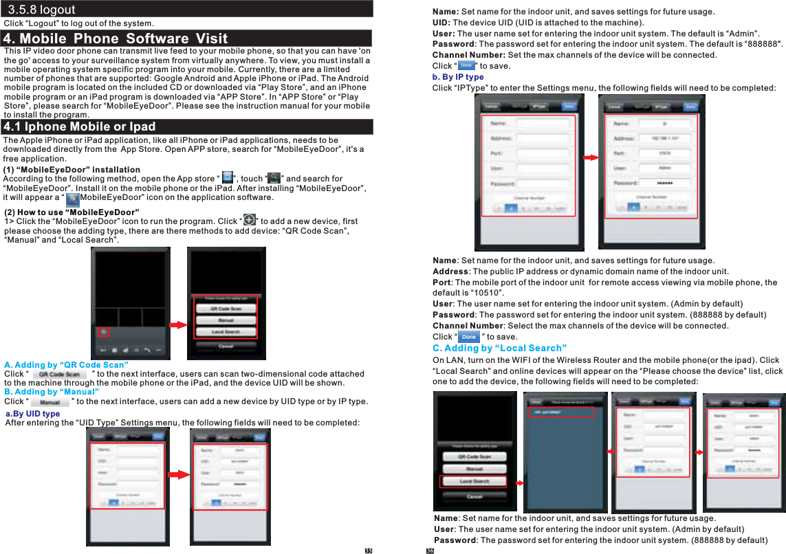
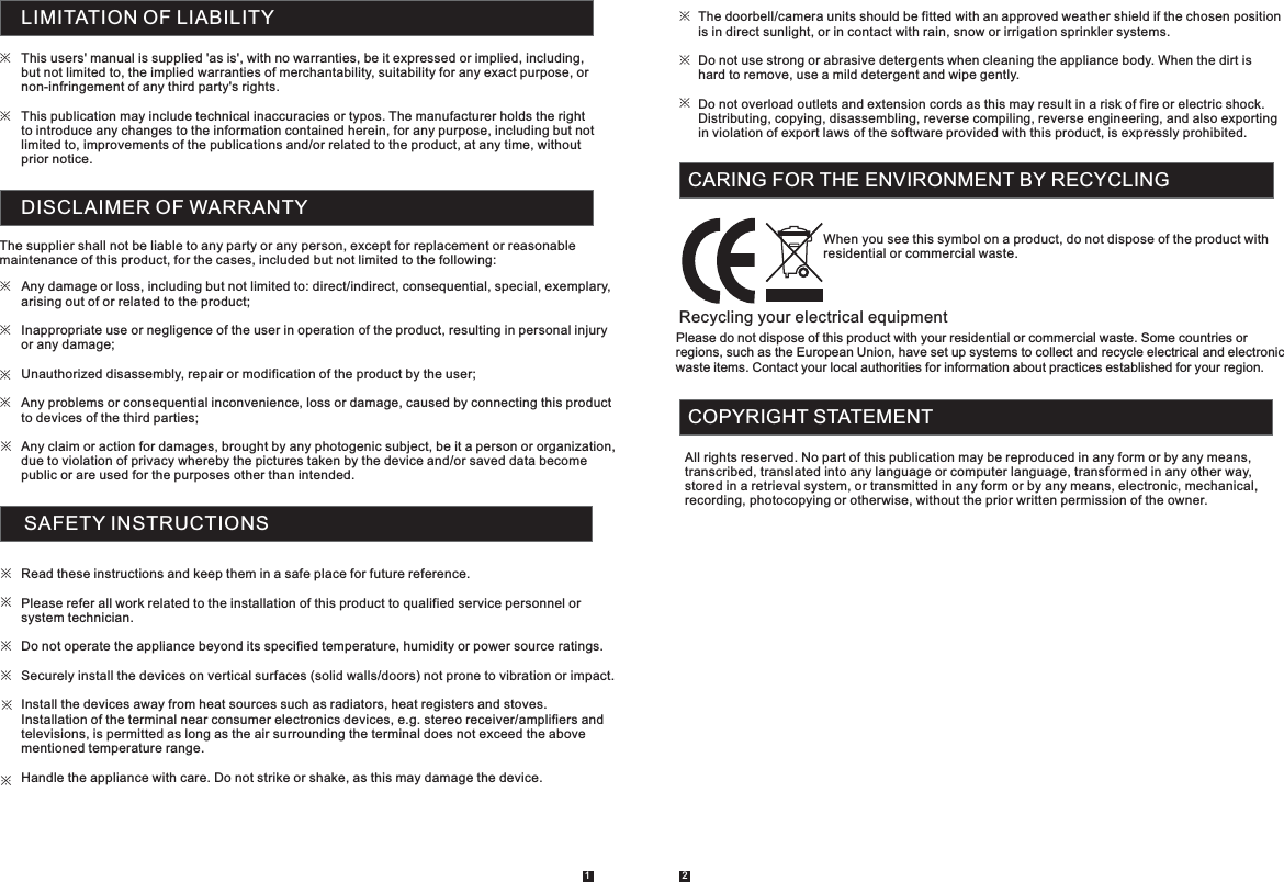
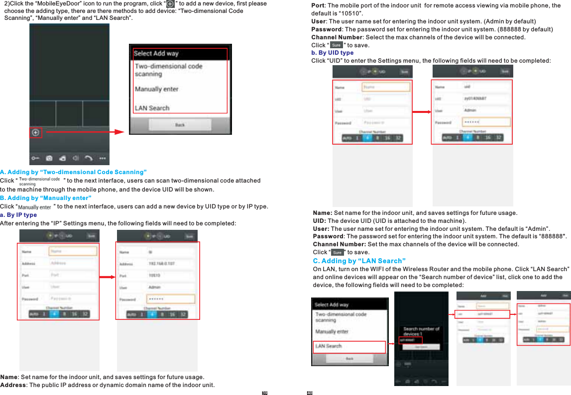
![Channel Number: Set the max channels of the device will be connected.Click “ ” to save.2> After adding the device successfully, the device will appear on the main screen. Click the device, and all the channels of the device will be shown on the screen. Click any channel and it will connect immediately. The background of the channel will be highlighted after connectingsuccessfully(shown as follows).3> The functions of the other icons on the live view: Unlock. Snapshot . : to capture a frame of the video stream as a still photoRecord: Click it to start manual record video on the current channel, and the right top corner of the channel has a normal recording video symbol “[REC]”. And click it again to stop manual record. Click it to turn the sound on or disable. Click it to start to talk, and the background of the button will be highlighted. Click it again to stop talking. Click it to display or hide the buttons “ ”. Click it to enter the device list interface. Click it to enter the snapshot file and record file. Click it to enter the local setting interface. Click it to enter user guide interface.4> On the live view, users can touch a channel on the screen and drag it to the other channel postion directly.5> On the interface of “Device”, user can edit the parameters of one device, click “ ” to the next interface as below. Click “ ” to enter edit mode to adjust the parameters. Click “ ” to save.And click “ ” to remove the information of the current device. [Alarm]: To access the interface about the parameters of one device, there is an option “Alarm” for alarm push function. When select “On”, it indicates that the alarm push function of the currentdevice is enabled. To enable alarm push function, users need to make sure the indoor unit and the 37 38mobile phone are both connected to internet. 6> Click one on the list to see the picture or the record. Note: 1)When the option “Alarm Setting” on the mobile software interface is set to “On”, and the order “Configuration--Network--Advanced--Mobile Phone--Push” on the remote indoor unit is enabled. When someone press the call button on any outdoor camera, the alarm information will be pushed to the phone. And users can click the alarm list to access to the video live view of the channel directly or access to the video live view to unlock for the outdoor camera .2)The alarm push function can be effective, and the device must be added by UID type. Click “ ” to enter the snapshot and record file interface. Click “Photos” or “Records” to switchdisplay interface. Click “ ” to enter edit mode, users can remove the file list that they want to. 7> Click “ ”to enter the “System Settings” interface as follows.[Video Views]: Select “1" and only one channel view will be shown on live view. Select “4" and quad channels view will be shown on live view.[Live Preference]: Options include “Real-time” and “Quality”. If choose “Real-time”, the video encoder of the channel for remote access viewing via mobile phone will consider to the frame first; 1)Please go to the android software market “Play Store” to search for “MobileEyeDoor” and install it. Or from the installation CD, copy the setup software “MobileEyeDoor.apk” to user's Android phone or to SD card.Open your “File Manager” in android phone, and find out the file “MobileEyeDoor” in your android phone memory or SD card. Click it to install the software. When the application hasfinished installing, the icon “ ” will display on the screen of the phone(shown as below).If choose “Quality”, the video encoder of the channel for remote access viewing via mobile phone will consider to the image quality first.4.2 Android Mobile](https://usermanual.wiki/LB-Technology/96330AW-CEM/User-Guide-2515214-Page-20.png)
![Channel Number: Set the max channels of the device will be connected.Click “ ” to save.3) After adding the device successfully, the device will appear on the main screen. Click the device, and all the channels of the device will be shown on the screen. Click any channel and it will connect immediately. The background of the channel will be highlighted after connectingsuccessfully(shown as follows).4) The functions of the other icons on the live view: Unlock. Snapshot . : to capture a frame of the video stream as a still photoRecord: Click it to start manual record video on the current channel, and the right top corner of the channel has a normal recording video symbol “[REC]”. And click it again to stop manual record. Click it to turn the sound on or disable. Click it to start to talk, and the background of the button will be highlighted. Click it again to stop talking. Click it to display or hide the buttons “ ”. Click it to enter the device list interface. Click it to enter the snapshot file and record file. Click it to enter the local setting interface. Click it to enter user guide interface.5) On the live view, users can touch a channel on the screen and drag it to the other channel position directly.6) On the interface of “Devices”, user can edit the parameters of one device, click “ ” to the next interface as below. Click “ ” to enter edit mode to adjust the parameters. Click “ ” to save.And click “ ” to remove the information of the current device.[Alarm Setting]: To access the interface about the parameters of one device, there is an option“Alarm Setting” for alarm push function. When select “On”, it indicates that the alarm push function of the current device is enabled. To enable alarm push function, users need to make sure the indoor unit and the mobile phone are both connected to internet. Note: 1)When the option “Alarm Setting” on the mobile software interface is set to “On”, and the order “Configuration--Network--Advanced--Mobile Phone--Push” on the remote indoor unit is enabled. When someone press the call button on any outdoor camera, the alarm information will be pushed to the phone. And users can click the alarm list to access to the video live view of the channel directly or access to the video live view to unlock for the outdoor camera.2) The alarm push function can be effective, and the device must be added by UID type. 41 427) Click “ ” to enter the snapshot and record file interface. Click “snapshot” or “record” to switchdisplay interface. Click “ ” to enter edit mode, users can remove the file list that they want to. Click one on the list to see the picture or the record.8) Click “ ”to enter the “System Settings” interface as follows.[Video Views]: Options include “1" and “4". Select “1" and only one channel view will be shown on live view. Select “4" and quad channels view will be shown on live view.[Video Style]: Options include “Original” and “Covered”.[Live Preference]: Options include “Real-time” and “Smooth”. If choose “Real-time”, the video encoder of the channel for remote access viewing via mobile phone will consider to the frame first; If choose “Smooth”, the video encoder of the channel for remote Appendix 1. Accessing the indoor unit via Mozilla Firefox1.First, install Firefox on Windows(This document will use Firefox 3.6 as an example )2. After installing Firefox, search for the “IE TAB” add-on for Firefox; this file is named “ie_tab_plus-1.95.20100930-fx+sm (IE Tab Plus (FF 3.6+).xpi”. (This file can be downloaded fromthe Mozilla website)3.To install: Open Firefox, then click “Tools”, and select “Privacy” and a dialog box will appear. Then choose tab which is named “Get Accessory Discreteness”, and copy and paste“ie_tab_plus-1.95.20100930-fx+sm (IE Tab Plus (FF 3.6+).xpi” into the address field. A dialog box will prompt you to install or cancel the program; choose “Install immediately.” After installing the program, restart Firefox Browser.4. Open Firefox and enter the indoor unit IP address in the address field.access viewing via mobile phone will consider to the image quality first.](https://usermanual.wiki/LB-Technology/96330AW-CEM/User-Guide-2515214-Page-22.png)