LENNOX Furnace/Heater, Gas Manual L0403509
User Manual: LENNOX LENNOX Furnace/Heater, Gas Manual LENNOX Furnace/Heater, Gas Owner's Manual, LENNOX Furnace/Heater, Gas installation guides
Open the PDF directly: View PDF ![]() .
.
Page Count: 8
USER'S INFORMATION
G12, G12R and G12X Series Units
i i • ,i
GABUNIT8 RETAIN THESE INSTRUCTIONS FOR FUTURE REFERENCE
502,253M
8/90
SuperP,edee 3188 FOR YOUR SAFETY
Do not store or use gasoline or other
Eflammable vapors and liquids in the
Ivicinity of this or any other appliance.
i
WARNING
Improper InStallation, adjustment, alter.
arian, service, or ma|nte_'tance can
cause Injury or property damage. Refer
to this manual. For assistance or addi-
tional Information, consult a qualified
Installer, service agency, or the gas
supplier.
,,=
Litho U,S,A,
.... FOR YO01_'SAFETY
WHAT TO DO IFYOU SMELL GAS:
• Do not try to light any appliance.
•Open windows.
•Do not touch any electrical swite,b; De
not use the phone In your building.
•Immediately call your gas suppl|er from
a neighbor's phone. Follow the gas
suppller's Instructions.
•If you cannot reach your gas supplier,
call the fire department.
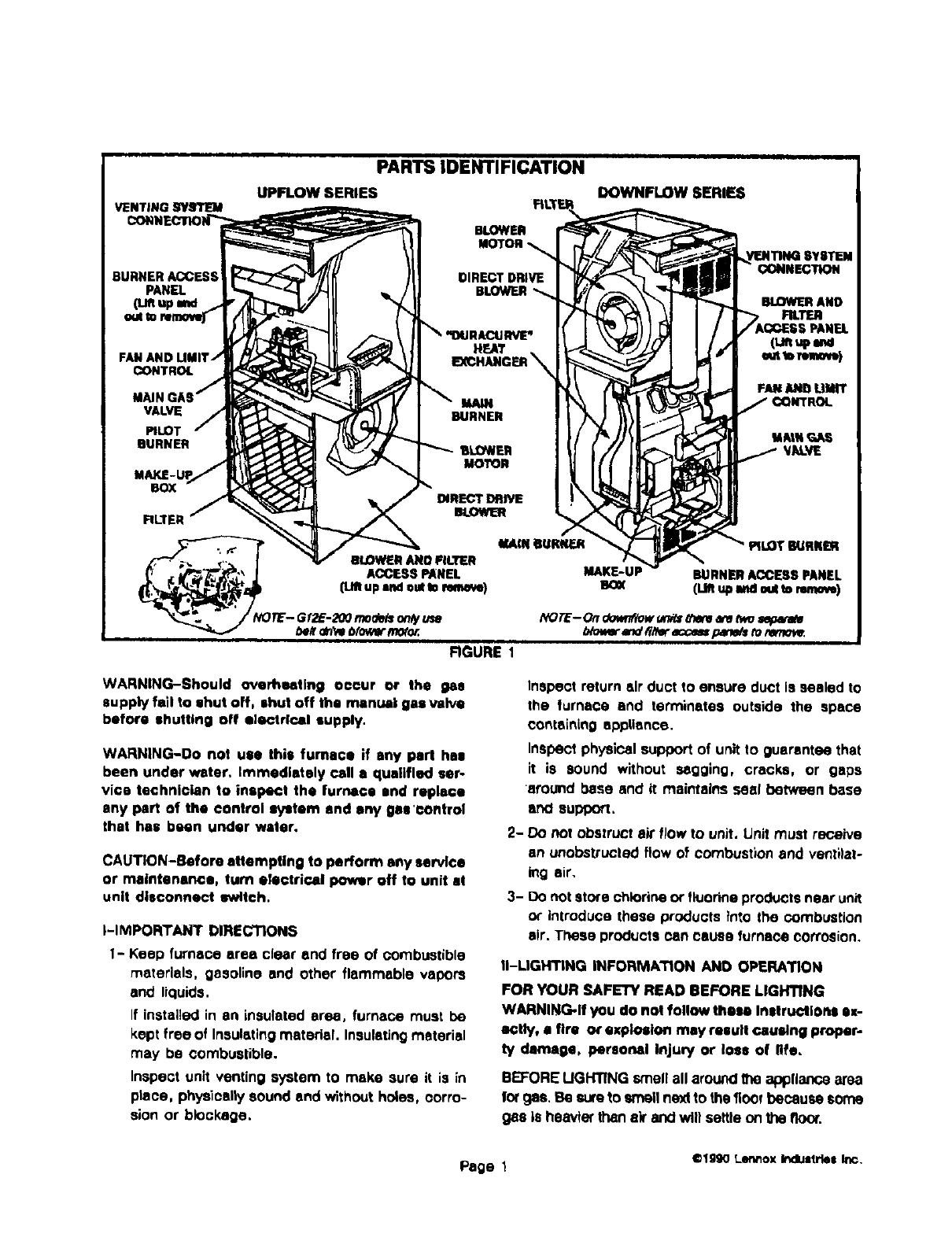
PARTSIDENTIFICATION
UPFLOW SERIES
BLOWER
DOWNFLOW SERIES
DIRECT
BLOWER
FAN AND
CONTROL
MAIN
VALVE
PILOT
BURNER
BOX
FILTER
HEAT
DIRECTDflIVE
FIGURE 1
WARNING-Should oyerhastlng occur or the ps
supply fell to shut off, shut off the manual gas valve
before shutting off electrical supply.
WARNING-Do not use this furnace if any pad has
been under water. Immediately call • qualified ser-
vice technician to inspect the furnace and replace
any pert of the €ontrol s_tem and any gas'control
that has been under water,
CAUTION-Before elf empties to perform any Nrvlce
or maintenance, turn electrical power off to unit el
unit disconnect switch.
i-IMPORTANT DIRECTIONS
1- Keep furnace area clear and free of combustible
materials, gasoline and other flammable vapors
and liquids,
If installed in art insulated area, furnace must be
kept free of Insulating material. Insulating material
may be combustible.
Inspect unit venting system to make sure it is in
piece, physically sound end without holes, corro-
sion or blockage,
CONNECTION
BLOWERAND
F'R.1T_
Inspect return sir duct to ensure duct is sealed to
the furnace end terminates outside the space
containing appliance.
Inspect physical support of unit to guerentee that
it is sound without sagging, cracks, or gaps
around base and it maintains seat between base
arx:l sopq:x_.
E- Do not obstruct aWflow to unit. Unit must receive
an unobstructed flow of combustion and ventilate
_ng air.
3- Do not store chlorine Or fluorine products near unit
or introduce these products into the combustion
air. These products Pan cause furnace coffosion.
II-LIGHTING iNFORMATiON AND OPERATION
FOR YOUR SAFETY READ BEFORE LIGHTING
WARNING-If you do not follow these Instructions ax-
_tly, a fire or explosion may result causing proper-
ty damage, personal Injury or loss of life.
BEFORE UGHTING smellall arounOthe appliance area
forgas, Be sore to smelt nextto thefloor because some
gas is heavier thanair and will settle on the floor.
Page 11¢19g0 Lermox Ir_llustrlel Inc,
Use.only your.hand to push in or turn the gas control
knob. Never use tools. If Ihe knob wit1not push in or turn
by hand, do not fly to repair I1,call a qualified service
tecrmicfan. Force or affempted repair may resuTtIn afke
or explosion,
This unit is equipped with an automatic "gasvalve using
a standing (constant) pilot flame or and intermittent
pilot (=E" and "X" series units). Standing pilot units
require manual lighting of pilot flame. Intermittent pilot
models have a pilot ignitor, Do NOT try to manually
light the pilot on an "E" or "X" series unit.
A-PlacMg Furnace In Operation
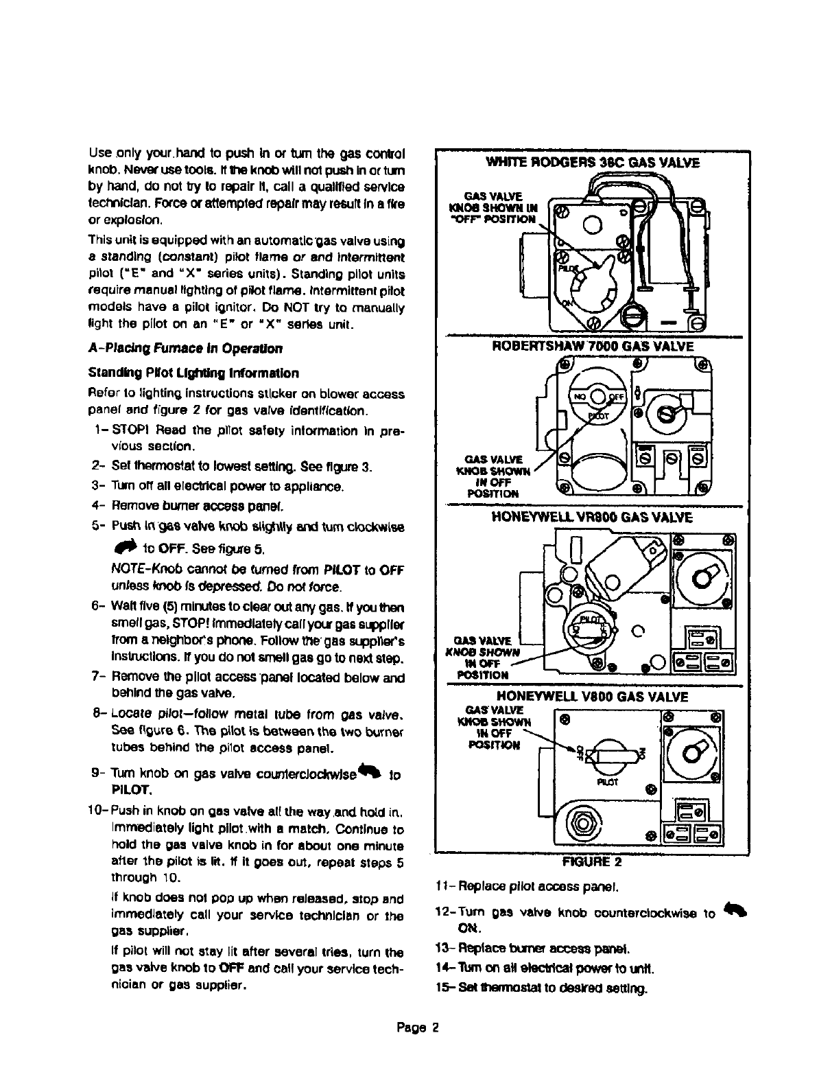
Stand_g Pltot Lighting Information
Refer to lightin_ instructions sticker on blower access
panel and figure 2 for gas valve identlflP._ticn.
1-S'I'OPI Read the pilot safety information in pre-
vious section,
2- Sol thermostat to lowest setting. See figure 3.
3- Turn off all electrical power to appliance.
4- Remove burner access panel.
5- Push in g6s vane knob s_ghtly and turn ck_ckw{se
_lb 1o OFf =. See figure 5,
NOTE-Knob cannot be turned from PILOT to OFF
unless knob fs de._'essed. Do not force.
6- Walt five (5) minutes to clear out any gas. If you
smell gas, STOP! Immediately call your gas s_llar
from •T0eighbor's phone. Follow tllegas suppl_or's
Instructions. If you do not smell gas go to next step.
7- Remove the pilot access panel located below and
behind the gas valve.
8-Locate pilot--follow metal tube from gas valve.
_ee figure 6. The I_tot is be_ee_ the two b_rnsr
tubes behind the pilot access panel.
9- Turn knob o_ gas valve countercJoc_vAse_l_ to
PILOT,
10- Push in knob on gas valve all the way.and ho_d in,
Immediately light pilot.with amatch. Continue to
hold the gas valve knob in for about one minute
after the pilot is lit, ff it goes out, repeat steps 5
through 10.
if knob does not pop up when reJeased, stop and
immediately call your service technician or the
gas supplier,
If pilot will not stay lit after several tries, turn the
gas valve knob to OFF and call your service tech-
nioian or gas supplier.
WHITE RODGERS 36C GAS VALVE
ROBERTSHAW 7000 GAS VALVE
P.._ VALVE
OAS"#a,LVE
POSITION
HONEYWELL VRS00 GAS VALVE
HONEYWE II VBO0 GAS VALVE
GASVALVE
!otis SHOWN
tit OFF
POSITION
FIGURE 2
f I- Replace pilot access panel.
12-Turn gas valve knob counterclockwise to 41_
ON.
13- Replace bumeTacsess panel
14-Turn _eH eleotdcaI pow_" to unit,
15- S_ B'mn'nostatto desk'edsetting.
Pope 2
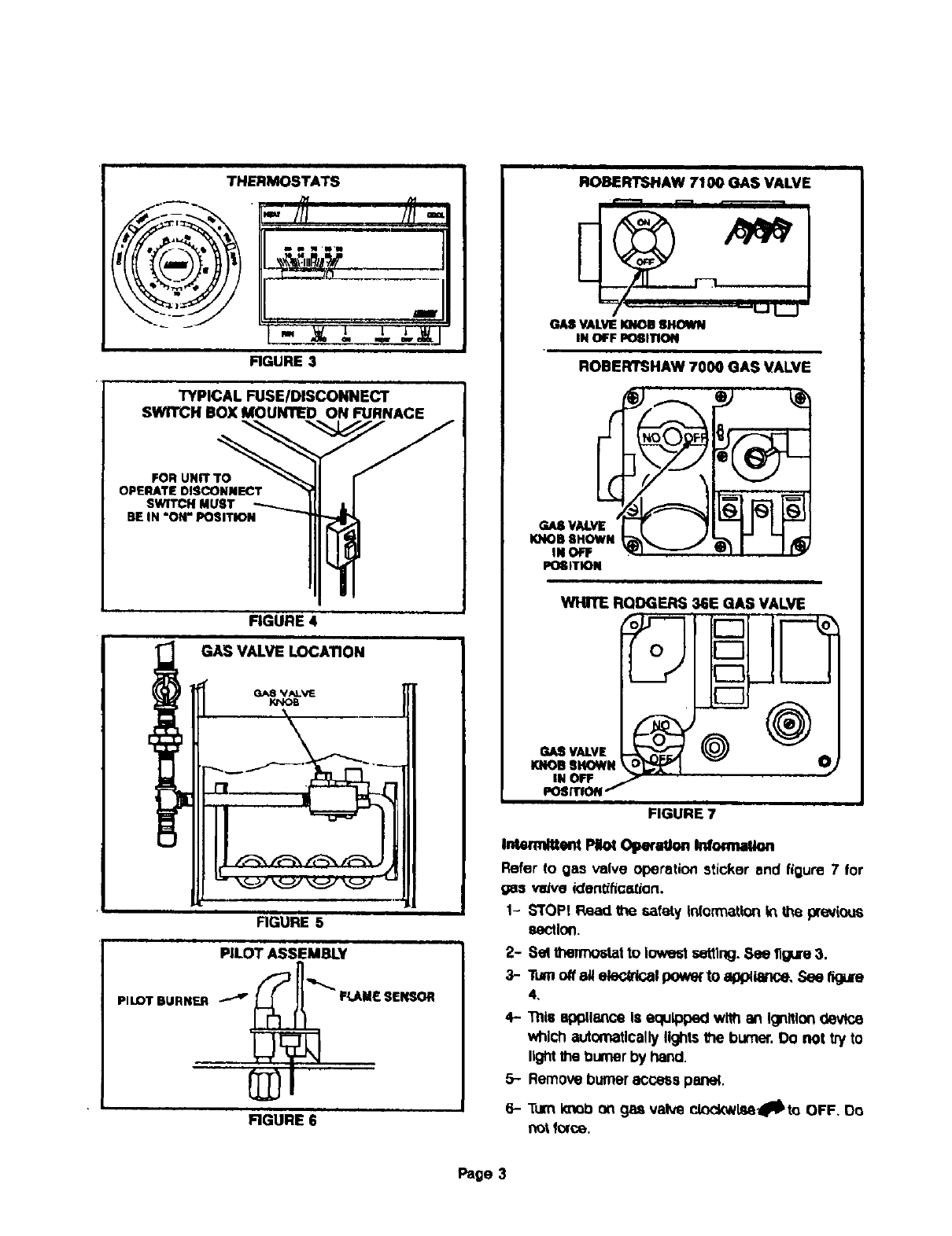
THERMOSTATS
FIGURE 3
TYPICAL FUSEIDISCONNECT
SWITCH BOX MOUNTED ON FURNACE
FOR UNIT TO
OPERATE DISCONNECT
SWITCH MUST
BF IN "Off' POSITION
FIGURE 4
GAS VALVE LOCATION
KNOB
FIGURE 5
PILOT ASSEMBLY
_n
PILOT BURNER _--_'_"'_ FU_M_ SFI_JOR
@l
FIGURE 6
ROBERTSHAW 7100 GAS VALVE
GASVALVEKNOB8_
IN OFF L_ITION
ROBERTSHAW 7000 GAS VALVE
POGITION
WIgTE RQDGERS 36E GAS VALVE
GASVALVE )_
KNOBSHOWN O_
IN OFF " ----
POSrllON/
FIGURE 7
k_mduent PI_ O_xaOo. _ormaUo.
Refer to gas valve operation sticker and figure 7 for
gas veJveictentifice_ion.
1- s'roPI Read the safety Infom_atlonin the previous
section.
2- 8el lt_nTx_lat to lowest settlng.See 11gure3.
3- Turnoff 8_ ete_dGal powe( to appllance. See figu[e
4,
4- Tills 8pl3tlol_'eIS equipped wi#l oft IOrtitlon(levite
which automatically lightsthe burner.Do not try to
lightthe l_umerby hand.
5- Remove burneraccess panel.
6- TurnKnot:)on gss valve clocl_l_l_to OFF, Do
not force,
Page 3
7- Waltfive(5)minutestocleatoutanygas.Ifyouthen
smellgas,STO_ IrTVllediotelycallyourgas supplier
froma nel_s phone. Follow (he gas supplrer's
instructions.If you do not smell gas go to ne)dstep.
8- Turnknob on gasvalve counlerclockwlse41_ to ON,
9- Replace burneraccess panel.
10- Turnon all electricalpower to unit.
11- Set thermostatto deslreclsetting.
12- if the appliance will not operate, follow _e Instmc-
lions "To Turn Off Gas To Unit"and call your service
technician orgas supplier.
B-To Turn Off Gas To Unit
1-Set thermostatto lowest setting.
2- Turnoff all electrical POwerto unitif service is to be
per/on'ned.
3- Remove unit access panel.
4- Turnknob .ongas valve clockwlseOIb 1oOFF. Do
notforce.
NOTE-On standing p/;or units, the gas valve knob
must be depressed sl/gt_tlyto lure to OFF. Do not
torce.
5- Replace unit access panel.
TABLE 1
FILTER'MEDIADIMENSIONo
D_
Unit .&lJ flll_ 1 in.
in. •In. I[mm •ram)
GfZS-200 62" A2il" It'L_lx 711
,_" x_e" 11130x7111
36" x28" (914 x?lt)
G f 2Q_1-82,
G12Q2/3X-60
Gf2QOE-62 _112Q3E..40
G12Q3_-2B
QI2Q;_. 110; (312Q3E- 110
G12Q3/4X-80;
_2C_E-;_b; G1204 -_10
G1203-137: G tZ_Q4.137
G 12Q</SX- 100;
G 12Q5-137; G12C_E-75
e 12QSE- 100, GI2COE- 137
G_204E-',3/: Gl_QS_-137
GI2Q_.lag
01f 2Q2X-40; G IL:'O2-5_
G1202-82; G1202E-40
GI202E-S$; O12D-110
Q1203E-_._ OIZDE-I TO
Q12RO2-f_; G12_0_-412
G f2RO2E-66
_f2RQ_-137
Q12RQ3E-110
G 12RO3-137;
G I2RQ6-137:G12RQS-137
G_2RQ_E-a_:
G12ROIS-1e15
FIIIw" TyPe
|Qu_mlty)
Hammo_ (13
H,tmmo=_t[t)
2,0t4a mmoek (1)
H_mmo¢_(t_
Hammock (f]
2t31Hs_m_k 11)
S_ab1_)
81=b(2I
Smb(2_
30" x28" (7_x 71+)
•qZ" _26" (BOOx _l_)
,_,= x2S* (l_t x 711
4,?."_26" _tos6x 71_
44P x_O* 11130x7_11
}S" x2S" (_x S25)
ID_x_O _x 1"
_:4 x SO8 x 2S)
12" x20" x 1"
16- M20- .q ) +
(406 x 50_ x 25)
f6"x_O'x f"
(40e x 50_ x 25)
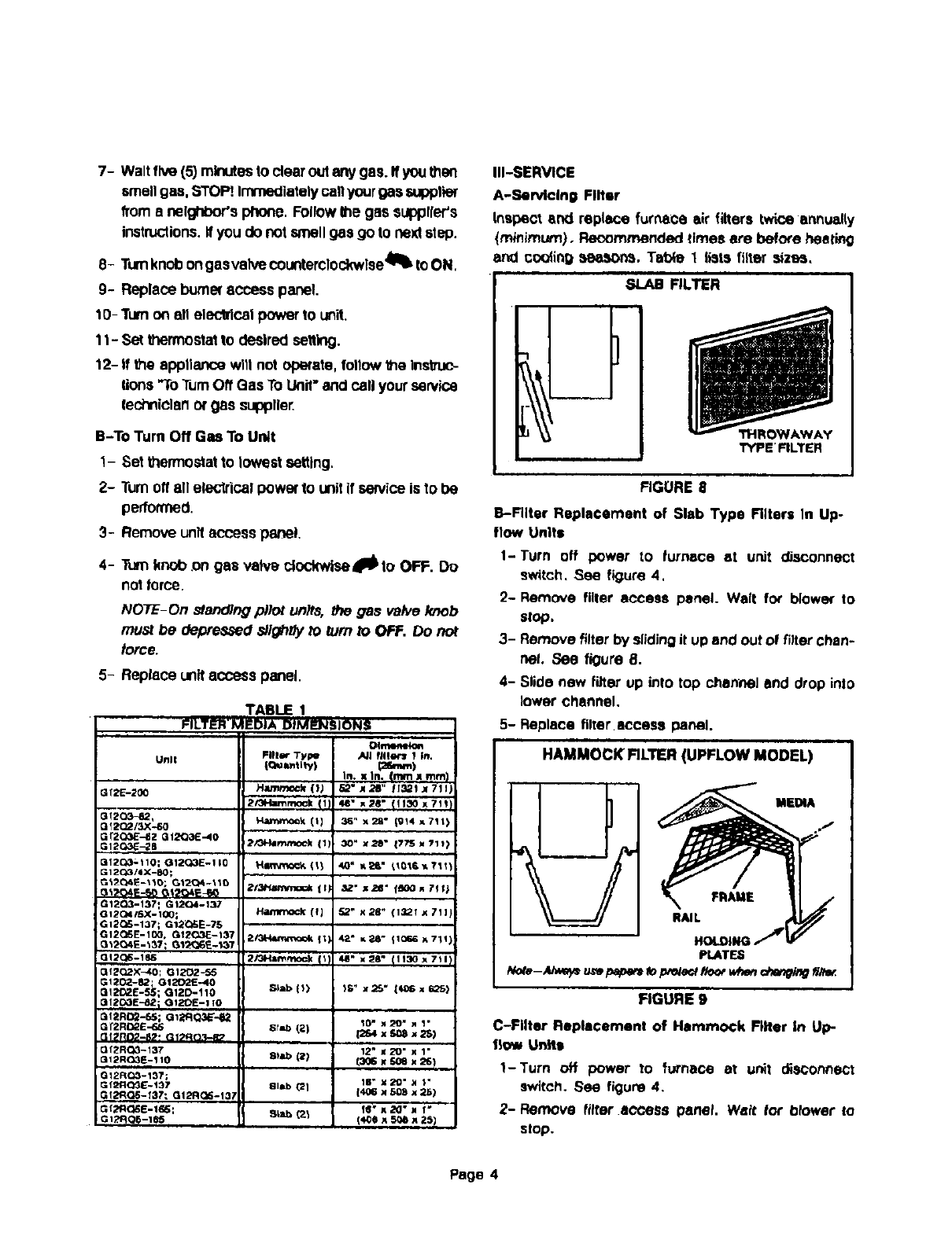
Ill-SERVICE
A-Servicing Filter
Inspect and repl_-e furnace air filters twice annually
(m_imum). Raceme'rended times ere before heating
and cooling seasons. Taf0_ 1lists filter sizes.
SLAB FILTER
TYPE' FILTER
FIGURE 8
B-Filter Replacement of Slab Type Filters In Up-
flow Units
1-Turn off power to lurnece at unit c_sconnect
switch, See figure 4,
'2- Remove filter access panel. Walt for blower to
slop,
3- Remove filter by siidJngit upand out of filter chan-
nel. See figure 8.
4- Slide new filter up into top channel and drop into
lower channel.
5-Replace filter.access panel.
HAMMOCK RLTER (UPFLOW MODEL)
MEDIA
RAIL
P_T_
FIGURE 9
C-Filter Replacement of Hammock Filter in Up-
11o_ Units
1-Turn off power to furnace at unit disconnect
switch. See figure 4.
2- Remove filter access panet, Welt for O_ower to
stop.
Page 4
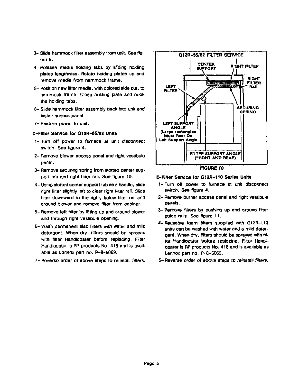
3- Slidehammockfilterassembly from unit, Sea fig-
ure g.
4-Release mecrm holding tabs by sliding holding
plates lenglhwise. Rotate holding plates up and
remove media from hammock frame.
5- Positionnew filter media, with cOlored side out, to
hammock frame, Close holding plate and hook
the holding tabs.
6- Slide .hammock fitter assembly back into unit end
install access 10anal.
7- Re=tore power to unil,
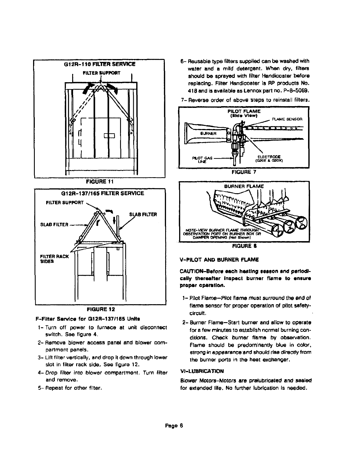
D-Filter Service for G12R-55!82 Units
1-Turn off power to furnace at unJt disconnect
switch. See figure 4.
2- Remove blower access panel and right vestibule
panel.
3- Remove seoudng spring from slotted center sup-
port tab and right litter rail, See figure 10.
4- Using slotted center support tab as s handle, slide
right filter s_ghtly left to clear right filter rail. Slide
filter downward to the right, below filter rail and
around blower and remove filter from cabinet.
5- Remove left fitter by ilfting up end around blower
and through right vestibule el:tuning.
6- Wash permanent slab filters with water end mild
detergent. When dry, filters should be sprayed
wifft filter Hendicoater before replacing. Filter
Handiooater is liP products No, 418 and is avail-
able as Lennox part no. P-8-5069.
7- Reverse order of above steps to reinstall fillers,
LEFT
LEFT SUPPORT
ANGLE
{Large rectangles
MUSt Rest On
Lilt support Angle
SEt-_LIRINO
SPRING
(FRONT AND REAR)
fiGURE 10
E-Filter Service for G12R-l_O Series U_ts
I-Turn off power to furnace at u_it disconnect
switch. Sea figure 4,
2- Remove burner access panel and right vestJbule
panels.
3-Remove filters by _ahing upend ,,round fil_er
guide rails. See figure 11.
4-Reusabk3 foam filters supplied with GI2R-lt0
units can be washed with water end a mild deter-
get_. Wt_endry, filters should be sDrayed w_h fil-
ter !4andk:oater _,_eforereplacb',g. F_er Han_-
teaser is RP products No. 418 and is available as
Lennox part no, P-8-5069.
5- Reverse order of above steps to reinstall filters.
Page 5
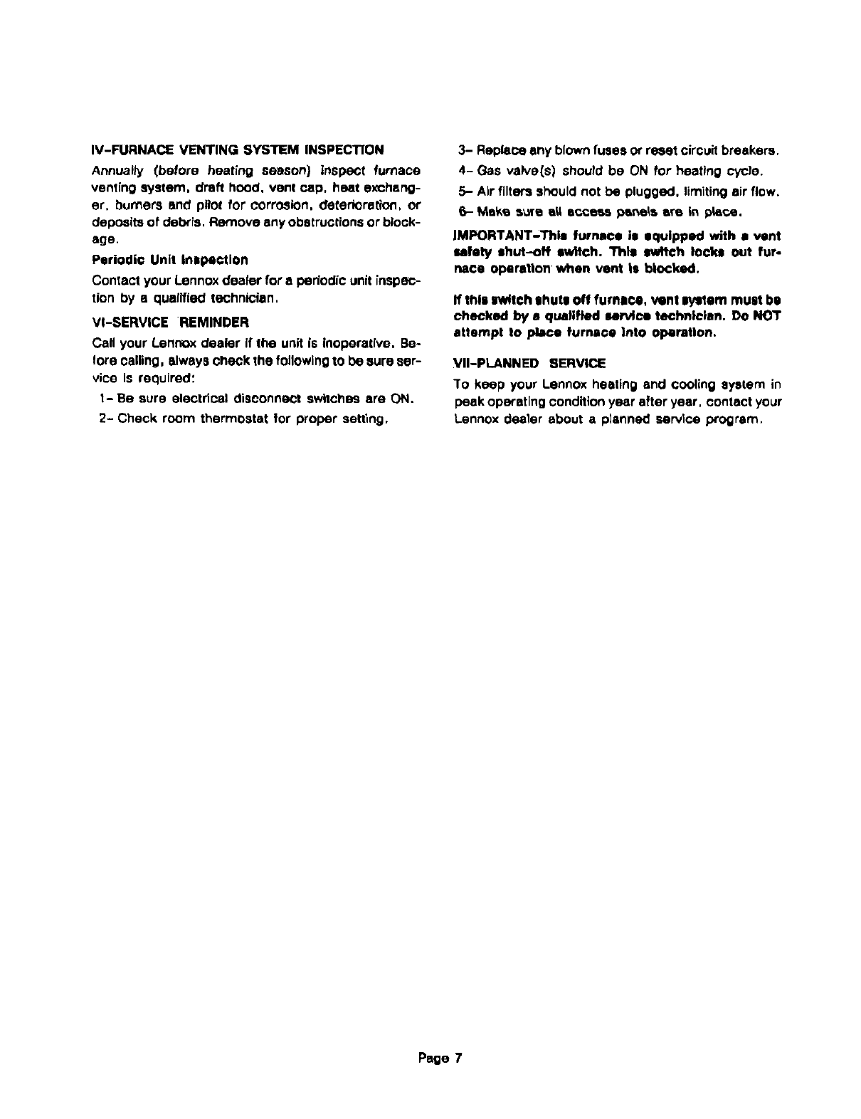
G12R-110FILTERSERVICE
FILTERStJPPO_r
//
d'
:,{--
q
FIGURE !1
G12R-137/165 FILTER SERVICE
FILTERSUppORT
FILTERRACK
SIDES
FIGURE 12
F-Filter Service for G12R-1371165 Units
1-Turn off power to furnace at unit disconnect
switch. See figure 4.
2- Remove blower access panel and blower com-
partment i_nels.
3- Lift filter vertically, and drop it down through lower
slot in litter rack side, Sea figure 12.
4-Drop filter into blower eomparlment. Turn frlter
and remove.
5- Repeat for other filter.
6- Reusable type filters supplied can be washed with
water end amild detergent. When dry. filters
should be swayed with filter Handicoater before
replacing. Filter Handicoater is liP products No.
418 and is available as Lennox part no. P-8-5069.
7- Reverse order of above steps to reinstall filters.
I
PILOT FLAME
(side View) FLAME SENSOR
FIGURE 7
FIGURE 3
V-PLOT AND BURNER FLAME
CAUTION-Before each heating season and periodi-
cally thereafter inspect burner flame to ensure
proper eI_rttlo_.
!- Pilot F)ame--Pt]o! flame must surround the end of
flame sensor for proper operation of pilot safety-
circuit.
2- Burner Flame--Start burner and allow to operate
for e few minutes to establish normal burning con-
ditions. Check burner" flame by observation.
Flame should be predominantly blue in color,
strong in appearance'and should dso directly from
the burner ports in the heat exchanger.
VI-LUBRICATION
BJower Mozore-Motors are prelubrlcated and sealed
for extended life. No further lubrication is needed.
Page 6
IV-FURNACEVENTINGSYSTEMINSPECTION
AnnuaIJy(before heating season) inspect furnace
venting system, draft hood, vent cap, heat exchang-
er, burners and p_ot for corrosion, deterioratlon, or
deposits of del_ia, Re.nave any obstructions or block-
age.
Periodic Unit Inspection
Contact your Lennox dealer for a periodic unit inspec-
tion by a qualified mchni_an.
VI-SERVICE REMINDER
CaN your Lennox dealer If the unit is Inoperative. Be-
lore calling, always check the following to De sure ser-
vice is required:
1- Be sure electrical disconn_.'t SWitChBS are ON.
2- Check room thermostat for proper setting,
3- Replace any blown fuses or re_t circuit breakers.
4- Gas valve(s) should be ON lot heating cycle.
5- Air filters should not be plugged, limiting air flow.
6- Make s_e a_,ie_.oeea pane_a ere In p_ca,
IMPORTANT-This furnace is equipped with •vent
safety shut--oN sw_tch. This switch locks out fur-
nace operation when vent is b|ocked.
thle Iv_tch shuts off fumloe, vent system must be
checked by aqualified san4ca technloisn. Do Nor
attempt to place furnace into operation,
VII-PLANNED SERVICE
To keep your Lennox heating and cooling system in
peak opiating condition year after year, contact your
Lennox dealer about a planned service program,
Page 7
