LENNOX Furnace/Heater, Gas Manual L0406231
User Manual: LENNOX LENNOX Furnace/Heater, Gas Manual LENNOX Furnace/Heater, Gas Owner's Manual, LENNOX Furnace/Heater, Gas installation guides
Open the PDF directly: View PDF ![]() .
.
Page Count: 32

¢:_2000 Lennox Industries Inc.
Dallas, Texas
INSTALLATION
INSTRUCTIONS
G24M Series
GAS FURNACE Technicld
504,1g7MSureLight_Ignition System _.L_PuF[T_')-bli_ations
02/2000
Supersedes 503.981M LithoUSA
RETAIN THESE INSTRUCTIONS
FOR FUTURE REFERENCE
i:-i:, i I
:::::::::::::_::::_:_::::::_:_:::_ _: : , ,, ........ r-
G24M Unit Dimensions ...................... 2
G24M Parts Arrangement .................... 3
G24M Gas Furnace ......................... 3
Shipping and Packing List .................... 3
Requirements .............................. 3
General ................................... 4
Combustion, Dilution& Ventilation Air .......... 5
Setting Equipment .......................... 8
Duct System .............................. 11
Venting ................................... 12
Gas Piping ................................ 19
Electrical ................................. 21
Unit Start-up .............................. 24
Gas Pressure Adjustment ................... 25
High Altitude Information .................... 25
Other Unit Adjustments ..................... 25
Service ................................... 27
Repair Parts List ........................... 28
Ignition Control Board Diagnostic Codes ...... 28
Troubleshooting ........................... 29
G24M Start-up & Performance Check Ust ..... 32
Do not store or use gasoline or oth-
er flammable vapors and liquids In
the vicinity of this or any other ap-
pliance.
Installation and service must be
performed by a qualified installer,
service agency or the gas supplier.
WHAT TO DO IF YOU SMELL GAS:
• Do not try to light any appliance.
• Extinguish any open flames.
•Do not touch any electrical switch; do not
use any phone in your building.
•Immediately call your gas supplier from a
neighbor's phone. Follow the gas suppli-
er's instructions.
•If you cannot reach your gas supplier, call
the fire department.
Page 1
GAS PIPING 2 (51) ELECTRICAL INLETS
INLET
FLUE
OUTLET "
1
1
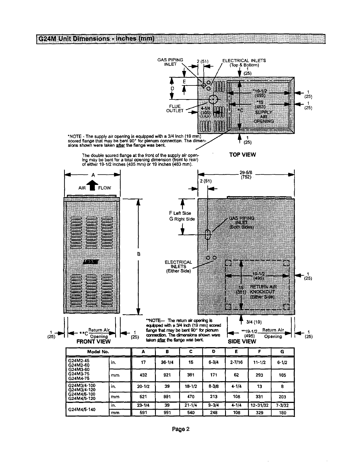
*NOTE - The supply air opening is _ with a 3/4 inch (19 n
scored flange that may
sionsshown were taken after the flange was bent,
The double scored flange at the front of the supply air open-
ing may be bent for a total opening dimension (front to rear)
of either 19-1/2 incheS(495 ram) or 19 inches (483 ram),
,4_ A -_----Ib
AIRtFLOW
(25
L
,ql'-**C_ _ 1
Opening- I (25)
FRONT VIEW
FLeft Side
ELECTRICAL
iNLETS
(Ei_erSide)
1
(25)
TOP VIEW
29-5/8
(752)
.3/4(19) II
19-1/2 ReturnAir_l L__ 1
(495) Opening Vl r" (25)
SIDE VIEW
Model No. A B C D E F G
G24M2-45 m. 17 36-1/4 15 6-3/4 2-7/16 1%1/2 6-1/2
G24M2-60
G24M3_60
G24M3-75 rnm 432 921 381 171 62 293 165
G24M4.75
G24M3/4-100 m, 20-1/2 39 18-1/2 8-3/8 4-1/4 13 8
G24M3/4.120
G24M4/5-100
G24M4/5-120 mm 521 991 470 213 108 931 203
m, 23-1/4 39 21-1/4 9-3/4 4-1/4 12-31/32 7-3/32
G24M4fS-140 mm 591 991 540 248 108 329 180
Page 2

G24M VENT ADAPTER _CABINET TOP I_
PARTS IDENTIFICATION HEATEXCHANGER
ASSEMBLY
FLUE BOX
COMBUSTION AIR
BLOWER _I
FRONT LOUVERED
PANEL
BURNER
AS_
CONTROL
BOARD
PRESSURE
PRIMARY
LIMIT _
LOW PRESSURE SWITCH
• Only)
TRANSFORMER
DOOR INTERLOCK SWITCH
NOx
TURBULATOR
SECONDARY
LIMITS
BLOWER ASSEMBLY
G24M
CABINET
CABINET
BOTTOM
The G24M gas furnace is shipped ready for installation
in the upflow position. The unit can easily be converted
for installation in either downflow or horizontal ap-
plications. The furnace is shipped with a bottom seal
panel in place for side return air in upflow applications.
Package I of 1 contains:
1-Assembled G24M unit (includes vent adapter except
for 140 kBtuh units)
1 - Vent adapter (140 kBtuh unitsonly)
The following additiona/items may be ordered separately,
ff required:
1 - Thermostat
1 - Externalfilter rack kit
1-Hanging bracket kit
1 - Propane/LP changeover kit
Check equipment for shipping damage. If you find any
damage, immediately contact the last carder.
LennoxG24M unitsare Amedcan Gas Association (AGA)
and Canadian Gas Association (CGA) cedified.
In the USA, installation of Lennox gas centralfurnaces must
conform with local building codes. In the absence of local
codes, units must be installed according to the current Na-
tional Fuel Gas Code (ANSI-Z223.1) in the United States.
The NationalFuel Gas Code is availablef/om the following
address:
Amedcan National StandardsInstitute, Inc.
11 West 42nd Street
NewYork, NY 10036
In Canada, installationmust conformwithcurrentNational
Standardof Canada CAN/CGA-B149.1 "Installation Code
for Natural Gas Burning Appliances and Equipment"and
CAN/CGA-B149.2 "Installation Cede for Propane Gas
Burning Appliances and Equipment," local plumbing or
waste water Codesand other applicablelocal codes.
Page 3
Adequate clearance must be made around the air open-
ings into the vestibule area. Provisions must be made for
proper operation and for combustion air and ventilation air
supply according to the current National Fuel Gas Code or
CAN/CGA-B149 standards.
Vent installations must be according to the provided vent-
ing tables and applicable provisions of local building codes.
This furnace is AGA and CGA certified for installation clear-
ances to combustible matedal as listedon the unit rating plate
and in the tables in figures 5, 7 and 9. Accessibility and ser-
vice clearances must take precedence over fire protection
clearances.
NOTE -For installation on combustible floors, the fumaca shall
not be installed directly on carpeting, b'le,or other combustible
material other than wood flooring.
For installation in a residential garage, the fumace must be
installed so that the bumer(s) and the ignition sourceare lo-
cated no tess than 18 inches (457 mm) above the floor.The
furnace must be located or protected to avcid physical darn-
age by vehicles.When a furnaceis installedina publicgarage,
hangar, or other building that has a hazardous atmosphere,
the furnace must be installed according to recomrnended
good practice requirements and current National Fuel Gas
Code or CAN/CGA B149.1 and B149.2 standards.
The furnace must be adjusted to obtain a temperature dse
within the range specified on the unit rating plate.
The G24M fumace must be installed sothat electrical com-
ponents are protected from water.
When the furnace is used with cooling units, it shall be
installed in parallel with, or on the upstream sideof, cooling
units to avoid condensation in the heating compartment.
With a parallel flowarrangement, a damper (or other means
to control the flow of air) must adequately prevent chilled air
from entedng the furnace. If the damper is manually oper-
ated, it must be equipped to prevent operation of either the
heating or the cooling unit, unless it is in the full "HEAT" or
"COOL" setting.
When installed,the furnace must be electricallygrounded
accordingto local codes. In addition, in the United States,
installationmust conformwith the currentNationalElectric
Code, ANSI/NFPA No. 70. The National Electric Code
(ANSI/NFPA No. 70) is available from the followingad-
dress:
National Fire Protection Association
1 Battery March Park
Quincy, MA 02269
In Canada, all electrical wiring and grounding for the unit
must be installed according to the current regulations of the
Canadian Electrical Code Part I (CSA Standard C22.1)
and/or local cedes.
Field wiring connections must meet or exceed specifica-
tions of type T wire and withstand a maximum temperature
rise of 180°F (82°C).
When the furnace is installed so that supply ducts carry air
circulated by the fumace to areas outside of the space con-
taining the furnace, retum air shall be handled by a duct(s)
sealed to the furnace casing and terminating outside space
containing furnace.
NOTE -G24M series unitsmust not be used as a construc-
tion heater during any phase of construction. Very low re-
turn air temperatures, harmful vapors and misplacement of
the fi#ers will damage the unit and lower its efficiency.
The Lennox G24M furnace may be installed in alcoves,
closets, attics, basements, garages and utility rooms in the
upflow, downflow, or hedzontal position.
This furnace design has not been AGA or CGA certified for
installation in mobile homes, recreational vehicles, or out-
doors.
AWARNING
These instructionsareintendedas a generalguideand de not
supersedelocalcodesinany way.Consult authoritieshaving
judsd_ before installation.
In additionto the requirementsoutlinedpreviously,the fol-
lowing general recommendationsshould be considered
when installingthe LennoxG24M furnace.
The furnaceshouldbe placed as closeto the centerof the
air distributionsystemas possible.Thefurnace shouldalso
be located closeto the chimneyorvent terminationpoint.
Do not installthe fumaca where drafts mightblow directly
intoit. This couldcause impropercombustionand unsafe
operation.
Do notblock fumaca combustionair openingswith cloth-
ing, boxes, doors,etc. Combustion airis needed for proper
combustion and safe unit operation.
When the furnace is installed in an attic or other insulated
space, keep insulation away from the furnace.
Page 4
ZkWARNING I AWARNING
In the past,therewas noproblemin bringinginsufticientout-
door airtor cembustien. Infiltrationprovidedalllie airthatwas
needed.Intoday'shomes,_ght _n p_ctJcesmakeit
necessary tobdnginairfrom outsideforcombustion.Takeinto
accountthat exhaustfans, appliancevents, chimneys,and
fireplaces forceadditionalairthat couldbe usedfor oombus-
tion outof the house.Unless outsideair is brm,'ghtintothe
houseforcombustion,negative pressure(outsidepressureis
greaterthan insidepressure)willbuildtothe pointthata down-
draft canoccurin_e fumacevent pipeorchimney.As a result,
cembustiongasesenterhe living spacecreatinga potentially
dangeroussituation.
In the absenceof localcodes concerning air forcombustion
and ventilation,use the guidelines and proceduresin his
sectionto installG24M furnaces to ensureefficientandsafe
operation.You mustconsidercombustionair needsand re-
quirementsfor exhaustventsend gaspiping.A portionof this
informationhas beenreprinted withpermission from the Na-
tionalFuel Gas Code (ANSI-7_'_3.1).This reprinted material
is not the completeandofficialpositionof theANSI onthe ref-
erencedsubject,whichis representedonly bythe standardin
its entirety.
In Canada, refer to the standard CAN/CGA B149.1 and
B149.2 installationcodes.
,CAUTION
All gas-firedappliancesrequire air forthe combustion pro-
cess. If sufficientcombustion air is not available,the fur-
nace or other appliance will operate inefficientlyand un-
safely.Enoughair must be providedto meetthe needs of all
fuel-burning appliances and apptiances such as exhaust
fans whichforce airout of the house. When fireplaces, ex-
haustfans, or clothesdryersare used at the same timeas
the furnace, much more air is required to ensure proper
combustionand to prevent adowndraft. Insufficientair
causes incompletecombustionwhich can resultincarbon
monoxide.
Inadditionto providingcombustion air,freshoutdoorairdi-
lutes contaminants in the indoor air. These contaminants
may include bleaches, adhesives, detergents, solvents
and other contaminantswhichcan corrodefurnacecompo-
nents.
The requirementsfor providingair for combustionand ven-
tilationdependlargely onwhether the furnace is installedin
an unconfinedor a confinedspace.
Unconfined Space
An unconfinedspace is an area such as a basement or
large equipmentroomwith a volume greater than50 cubic
feet (1.42 m3) per 1,000 Btu (.29 kW) perhourof the com-
binedinput ratingof all appliances installedinthat space.
This space also includes adjacent rooms which are not
separated bya door.Thoughan area may appear to be un-
confined,it might be necessary to bdngin outdoorair for
combustion if the structuredoesnot provide enoughair by
infiltration.If the furnace is located in a building of tight
constructionwith weather stripping and caulkingaround
the windows and doors, followthe procedures in the air
from outsidesection.
Page 5
ConfinedSpace
Aconfinedspaceis an area witha volumelessthan50 cubic
feet (1.42 m3) par 1,000 Bto (.29 kW) par hourof the com-
bined input rating of all appliancesinstalled inthat space. This
definition includesfurnace closets or small equipment rooms.
When the fumace isinstalledso that supplyducts carryair cir-
culated by the furnace to areas outside the space containing
the fumace,the retumair must be handledby ducts whichare
sealedto the fumaca casing and which terminate outs;dethe
space containing the furnace. This is especially important
whenthefurnaceismountedonaplatforminaconfinedspaoe
suchas a closetor smallequipmentroom.Even a smallleak
aroundthe base of the unitat the platformorat the returnair
ductconnection can cause a potentiallydangerousnegaUve
pressurecondition. Airfor combusiton and ventilationcan be
brought intothe confinedspace eitherfrominsidethe building
orfromoutside.
EQUIPMENT IN CONFINED SPACE
ALL AIR FROM INSIDE
CHIMNEY
G24M
FURNACE
i i I I II II Ii i i i i i i
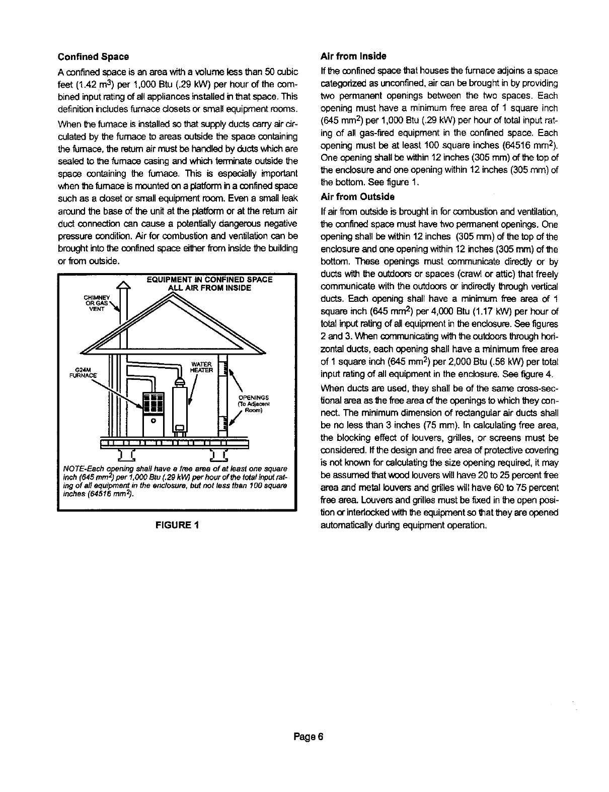
NOTE-Each opening shall have a free area of at least one square
inch (645 mmz) per 1,000 Btu (.29 kW) per hour of the total inputrat-
ing of all equipment in the enclosure, but not teas then 1O0square
inches (64516 mrn2).
FIGURE 1
Air from Inside
If theconfinedspacethathouses the furnace adjoinsa space
categorized as unconfined,aircan be broughtinby providing
two permanent openings between the two spaces. Each
opening must have a minimum free area of 1 square inch
(645 mm2) per 1,000 Btu (.29kW) per hour of total input rat-
ing of all gas-fired equipment in the confined space. Each
opening must be at least 100 square inches (64516 ram2).
One opening shall be within 12 inches(305 mm)of the topof
the enclosureandone opening within 12 inches (305 ram) of
the bottom. See figure 1.
Air from Outside
If airfrom outsideis brought infor cornbustionand ventilation,
the confinedspacemusthave two permanentopenings.One
opening shall be within 12 inches (305 mm) of the top of the
enclosure and one openingwithin 12 inches (305 mm) of the
bottom. These openings must communicate directly or by
ducts with the outdoorsor spaces (crawl or attic) that freely
communicate withthe outdoors or indirectly through vertical
ducts. Each opening shall have a minimum free area of 1
square inch(645 mm2) par 4,000 Btu (1.17 kW) per hour of
totalinput ratingof allequipmentin the enclosure.See figures
2 and 3. When communicatingwith the outdoorsthrough hod-
zontal ducts, each opening shall have a minimum free area
of 1 square inch(645 mm2)par 2,000 Btu (.55 kW) par total
input rating of all equipment in the enclosure. See figure 4.
When ducts are used, they shall be of the same cross-sec-
tionalarea as the free area of the openings to which they con-
nect. The minimum dimension of rectangular air ducts shall
be no less than 3 inches (75 mm). In calculating free area,
the blocking effect of louvers, gdlles, or screens must be
considered. Ifthe design and free area of protective covering
is not known for calculatingthe size opening required, it may
be assumed that wood louvers will have 20 to 25 percentfree
area and metal louvers and grineswill have 60 to 75 percent
free area. Louvers and grilles must be fixed in the open posi-
tion orinterlockedw_ the equipmentso thattheyare opened
automaticallydudngequipmentoperation.
Page 6
CH{MNEY OR
GAS VENT _1
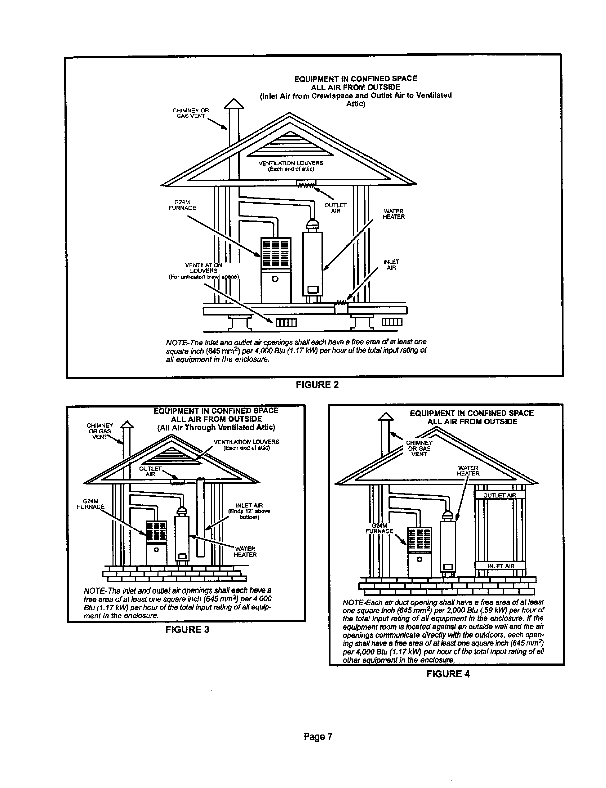
EQUIPMENT IN CONFINED SPACE
ALL AIR FROM OUTSIDE
(Inlet Air from Crawlspace and Outlet Air to Ventilated
Attic)
G24M
FURNACE
VENTILATION LOUVERS
(EaCh end of atdc)
WATER
HEATER
VENTILATION
LOUVERS
(For uni_ealed craw!
rrrrn rrrmi
NOTE- The inletand outJefairnpemngs shafteach have a free area of at least one
square _ch {645 turn2) per 4,000 Btu (1.17 kW) per hour of thetotalinputrating of
a/! equipment in the enclosure.
FIGURE 2
EQUIPMENT IN CONFINED SPACE
ALL AIR FROM OUTSIDE
(All Air Through Ventilated Attic)
VENTILATIONLOUVERS
(Eachendof ate)
G24M
FURNACE
NOTE-The inletand outJetair openings 8hall each have a
free area of at least one square inch (645 mm2)per 4,_0
Btu (1.17 kW}per hour of the total input ratingof all equip-
ment in the enstosure.
FIGURE 3
FIGURE 4
P_e7
ii i i ii ii ; il; = iiiiiiiiiiil
The Lennox G24M multi-position gas furnace can be
installed as shipped in upflow or horizontal position with
right-hand or left-hand discharge. The furnace can easi-
ly be converted for downflow applications.
Select a location that allows for required clearances
listed on the unit rating plate. Also consider gas supply
connections, electrical supply, vent connection and
installation and service clearances [24 inches (610 mm)
at unit front].
NOTE -1/3 and 1/2 hp blower motors are equipped with ei-
ther four flexible mounting legs or three flexible legs and
one rigid leg. The dgid leg is equipped with a shipping bolt
and a flat white plastic washer (rather than the rubber
mounting grommet used witha flexible mounting leg). This
shipping bolt and flat washer must be removed before the
furnace is put into operation. Once the shippingbolt and
washer are removed, the rigid leg will not touch the fan
housing.
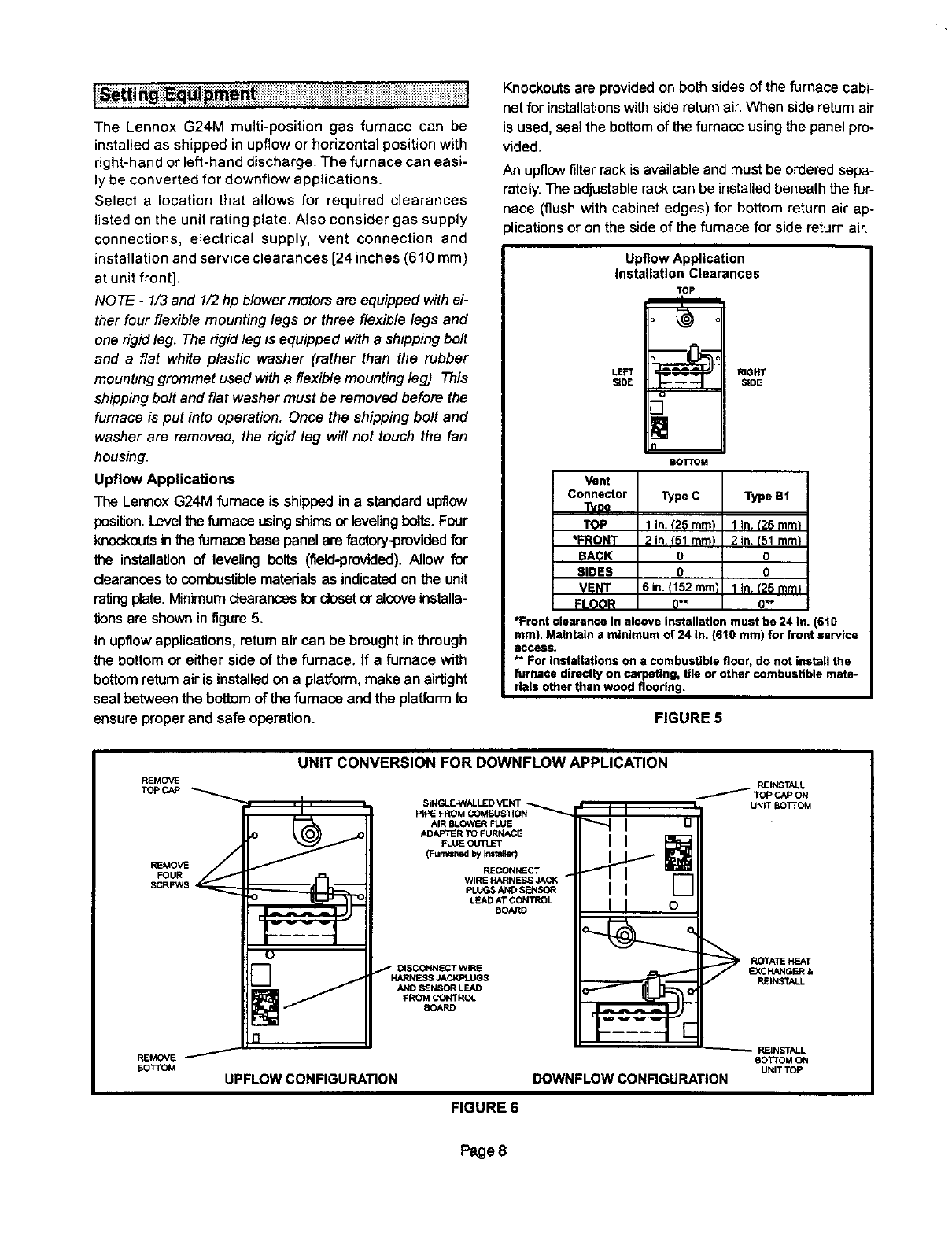
Upflow Applications
The LennoxG24M furnace is shipped in a standardupflow
position.Level_furnaceusing shimsor levelingbolts. Four
knockoutsinthefumaca b_se panelare factory-providedfor
the installationof leveling bolts (field-provided).Allow for
clearancesto combustiblematerialsas indicatedon the unit
ratingplate.Minimumclearances for closetoralcove installa-
tionsare shownin figure5.
In upfiowapplications, returnair can be broughtin through
the bottom or either side of the furnace. If a furnace with
bottomreturnair is installedona platform,make an airtight
seal between the bottomof the furnace and the platformto
ensure properand safe operation.
Knockouts are provided on both sidesof the furnace cabi-
net for installations with side return air. When side return air
is used, seal the bottom of the furnace using the panel pro-
vided.
An upflow filter rack is available and must be ordered sepa-
rately. The adjustable rack can be installed beneath the fur-
nace (flush with cabinet edges) for bottom return air ap-
)lications or on the side of the furnace for side return air.
Upflow Application
Installation Clearances
LEFT
SIDE
TOP
BOTTOM
RIGHT
S;DE
1 in. t'25 ram) 1In. (25 mm_ I
2in.(51mm) 2in.(51mm}]
0 0
0 o
6in.(152mm) 1in.(25mm}i
0" 0"
*Front clearance in alcove Installation must be 24 in. (610
ram). Maintain a minimum of 24 in. (610 rnm) for front service
eccess.
*" For installations on acombustible floor, do not install the
furnace directly on carpeting, tile or other combustible mate-
rials other than wood flooring=
Vent
Connector Type C Type BI
Twe
TOP
*FRONT
BACK
SIDES
VENT
FLOOR
FIGURE 5
REMOVE
TOPCAP
REMOVE
FOUR
SCREWS
REMOVE
BOTTOM
UNIT CONVERSION FOR DOWNFLOW APPLICATION
SINGLE-WALLED VENT ,,.._.,..,._._
PtPE FROM COMBUSTION
AIR BLOWER FLUE
ADAPTER TO FURNACE
FLUIE OUTLET
(FumW_ed by Imta_eq
RECONNECT
WIRE HARNESS JACK
PLUGS AND SENSOR
LEAD AT CONTROL
BOARD
DISCONNECT WIRE
HARNESS JACKPLUGS
AND SENSOR LEAD
FROM CONTROL
8OARD
UPFLOW CONFIGURATION
'II
I I o
PJEINSTALL
/Topc,,.-oN
UNIT BOTTOM
ROrATE HEATEXCHANGER &
REINSTALL
_-- REIN_rALL
BOTTOM ON
UNIT TOP
DOWNFLOWCONFIGURATION
FIGURE 6
Page 8
DownflowApplications
The LennoxG24M furnace is shippedinthe upflowconfig-
uration and must be converted for downflow installation.
Refer tofigure6 and the followingstepsto convertthe unit
for downflowinstallation:
1 - Place uniton its back and remove access panel.
2- Disconnect wire harness jackplugs from control
board.
3 - Disconnect sensor lead from control board.
4 - Remove four screws securing cabinet top cap to cabi-
net.
5 - Remove four screws holding heat exchanger assem-
bly in place. Slide heat exchanger out through top of
cabinet.
6 - Rotate heat exchanger 180° and slide back into cabi-
net throughtop. Resecure using four screws.
7 - Remove four screws securing cabinet bottom piece
to cabinet. Replace with cabinet top cap.
8 - Use four screws to install cabinet bottom piece where
cabinet top was.
9 - Reconnect sensor lead to control board.
10- Reconnectwire harness jackptugs to control board.
11- Replace unit access panel.
12- Use cord clip located on right side of furnace to
hold wiring away from hot surfaces in heating
compartment. Install two #10 sheet metal screws in
cabinet top to provide a better air seaL
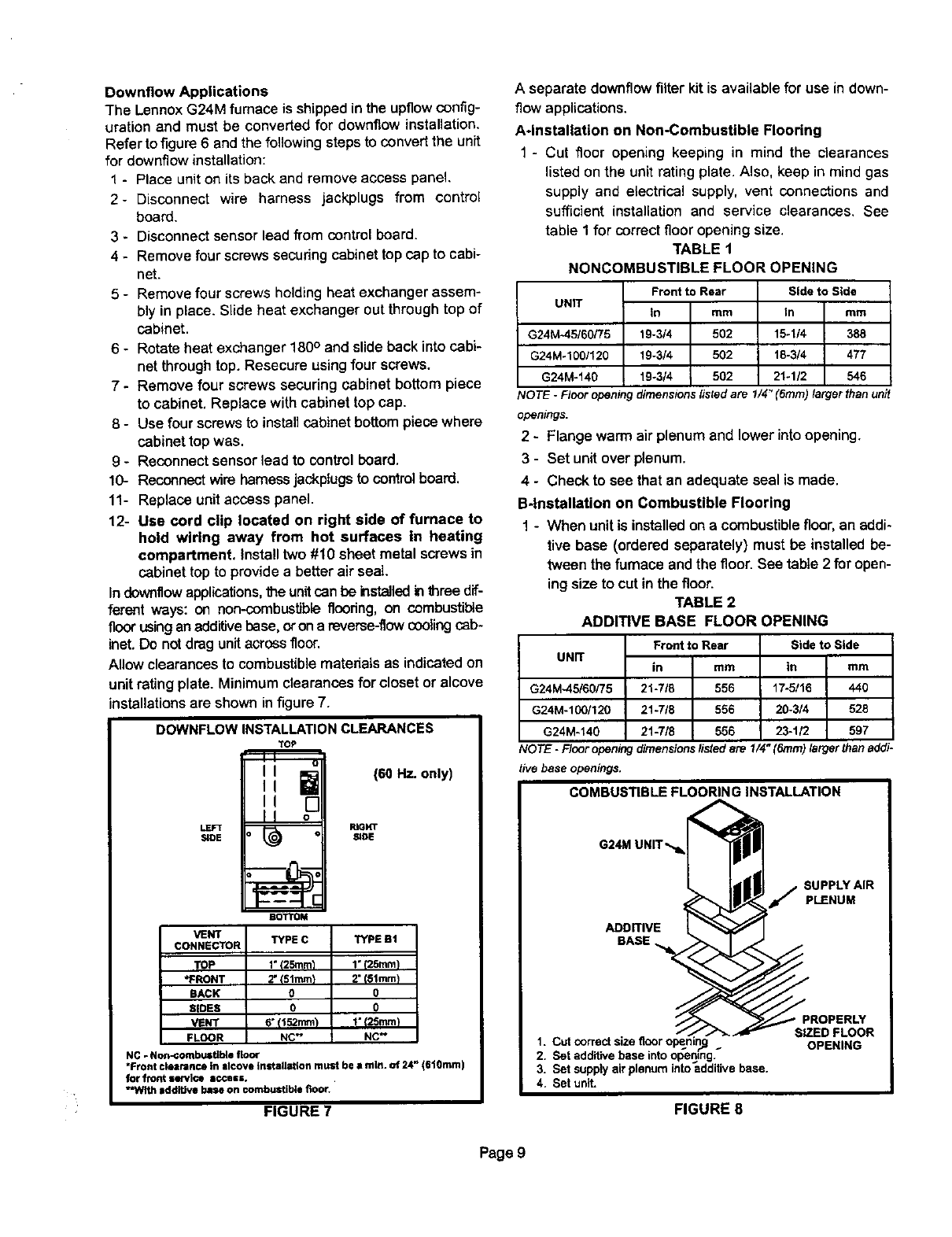
Indownflowapplications,the unitcan be installedinthree dif-
ferent ways: on non-combustibleflooring, on combustible
floor using an additivebase, oron areverse-flow cooling cab-
inet. Do not drag unit across floor.
Allow clearances to combustible materials as indicated on
unit rating plate. Minimum clearances for closet or alcove
installations are shown in figure 7.
DOWNFLOWINSTALLATIONCLEARANCES
TOP
(60 Hz. only)
LEFT RIGHT
SIDE SiDE
BOTTOM
VENT TYPE C TYPE Bt
CONNECTOR
TOP 1"I25mm_ 1*125mint
•FRONT 2"I51mm) 2" t81mm)
BACK 0 0
SIDES 0 0
VENT 6" {r 52rnm'p I" t25mrn_
FLeeR NC" NC"
NC - Non-combustible floor
"Front clearance In Ilcove Install_tion must be • nlln. of 24" (610rnm)
for front service IOCaKK.
"With addiUve base on combustible floor.
FIGURE 7
A separate downflow filter kit is available for use in down-
flow applications.
A*lnstallation on Non-Combustible Flooring
1 - Cut floor opening keeping in mind the clearances
listed onthe unit rating plate. Also, keep in mindgas
supply and electrical supply, vent connections and
sufficient installation and service clearances. See
table 1for correct flooropening size.
TABLE 1
NONCOMBUSTIBLE FLOOR OPENING
G24M*45/60/75
G24M-1001120
G24M-140
Front to Rear
UNIT In mm
19-3/4 502
19-3/4 502
19-3/4 502
Side to Side
In mm
15-1/4 388
18-3/4 477
21÷1/2 546
COTE-Flooropeningdimensionslistedare 1/4"(6rnm) larger than unit
openings.
2 - Flange warm air plenumand lower into opening.
3 - Set unitover plenum.
4 - Check to see that an adequate seal is made.
B4nstallation on Combustible Flooring
1 - When unit is installedon a combustiblefloor,an addi-
tive base (ordered separately) must be installedbe-
tween the furnace and the floor. See table 2 for open-
ing size to cut in the floor.
TABLE 2
ADDITIVE BASE FLOOR OPENING
UNIT
G24M-45/60/75
G24M-100/120
G24M.140
Front to Rear
in rnm
21-7/8 556
21-718 556
21-718 556
Side to Side
in mm
17-5/t6 440
20-3/4 528
23-1/2 597
NO TE -Floor opening dimensionslistedare 1/4" (6ram) larger than addi-
tive base openings.
COMBUSTIBLE FLOORING INSTALLATION
G24M
ADDITIVE
BASE
SUPPLY AIR
_" PLENUM
1. Cut correct size floor _:
2. Set additive base into opening._
3. Set supply air plenum into additive base.
4. Set unit,
FIGURE 8
SIZED FLOOR
OPENING
Page 9
2-After opening is cut, set the additive base into opening.
3 - Check fiberglass strips on additive base to make sure
they are propedy glued and positioned.
4 - Lower supply air plenum into additive base until ple-
num flanges seal against fiberglass strips.
5- Set unit on additive base so unit flanges drop into ple-
num. Refer to figure 8.
NOTE -Be careful not to damage fiberglass strips.
Check for tight seal
C-installation on Cooling Cabinet
1 - Refer to reverse-flow coil installationinstructions for
correctlysized openinginfloorand installationof cabi-
net.
2- When cooling cabinet is in place, installfurnace so
flanges drop insidecabinet opening.
3-Seal cabinet and check for air leakage.
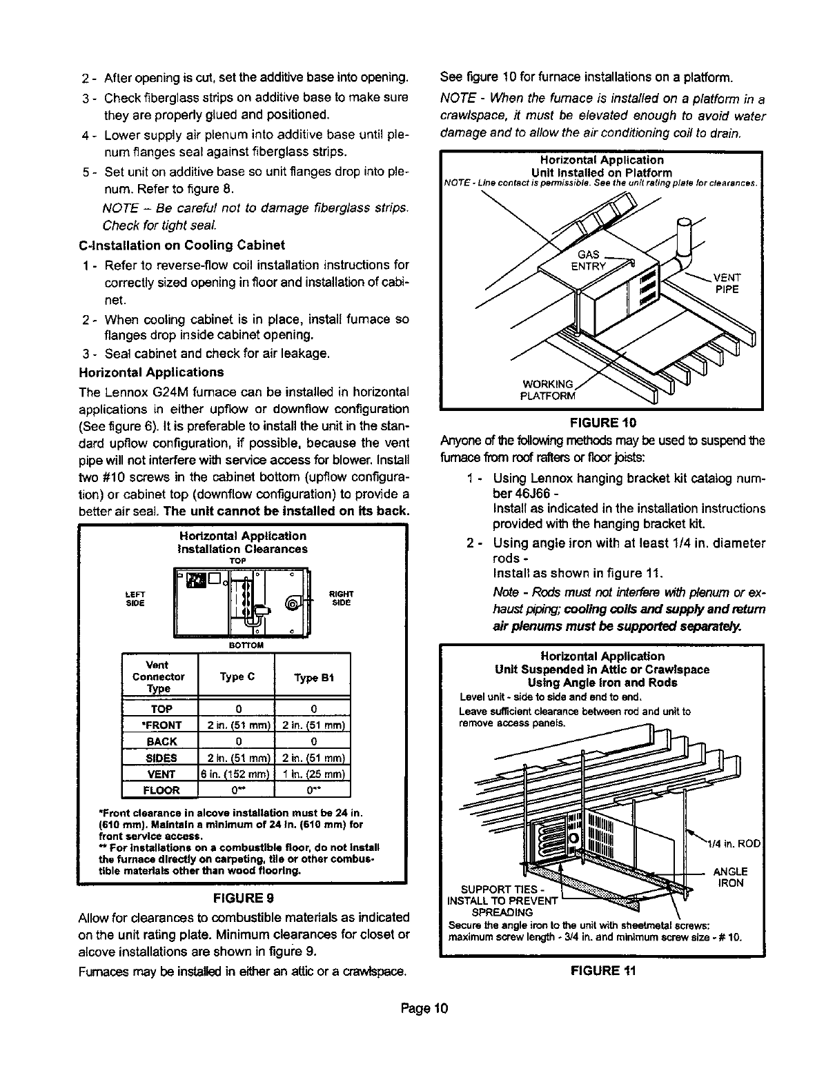
Horizontal Applications
The Lennox G24M furnace can be installed in horizontal
applications in either upflow or downflow configuration
(See figure6). It is preferable to installthe unit in the stan-
dard upflow configuration,if possible, because the vent
pipewill not interferewithserviceaccess forblower. Install
two #10 screws in the cabinet bottom (upflow configura-
tion) or cabinet top (downflow configuration)to provide a
betterair sea]. The unit cannot be installed on its back.
HorizontalApplication
installation Clearances
TOP
SIDE S_DE
BOTI'OM
Vem
Connector
Type
TOP
*FRONT
SACK
SIDES
VENT
FLOOR
Type C
0
2in. (51 ram)
0
2in. (51 rnm)
6 in. (152 ram)
0._
Type BI
o
2 in. 151 ram)
0
2 in. (51 ram)
1 in. (25 turn
0"*
*Front clearance in alcove installation must be 24 in.
(610 ram). Maintain aminimum of 24 in, (610 ram) for
front service access,
** For installations on a combustible floor, do not install
the furnace directly on carpeting, tile or other combus-
tible materials other than wood flcorlng.
FIGURE g
Allow for clearancesto combustiblematerials as indicated
on the unit ratingplate. Minimum clearances for closet or
alcove installationsare shown infigui'e9.
Furnaces may be installed in either an atticor a crawispace.
See figure 10 for furnace installationson a platform.
NOTE -When the furnace is installed on a platform in a
crawlspace, it must be elevated enough to avoid water
damage and to allow the air conditioning coil to drain.
Horizontal Application
Unit Installed on Platform
_IOTE-Linecontactis permissibleSeethe unitrating plateforclearances.
_VENTPIPE
WORKING
pLATFORM
FIGURE 10
Anyone ofthefollowingmethodsmay be usedtosuspendthe
furnace fiom roofraftersorfloor joists:
1 - Using Lennoxhanging bracket kit catalog num-
ber46366 -
Install as indicatedin the instaltationinstructions
providedwiththe hangingbracketkit.
2 - Using angle iron with at least 1/4 in. diameter
rods -
Install as shown in figure 11.
Note -Rods must not inter[erav_h plenum or ex-
haustpiping; coolingcoils and supplyand return
air plenums must be supported separately.
FIGURE 11
Page 10
IAWARNING
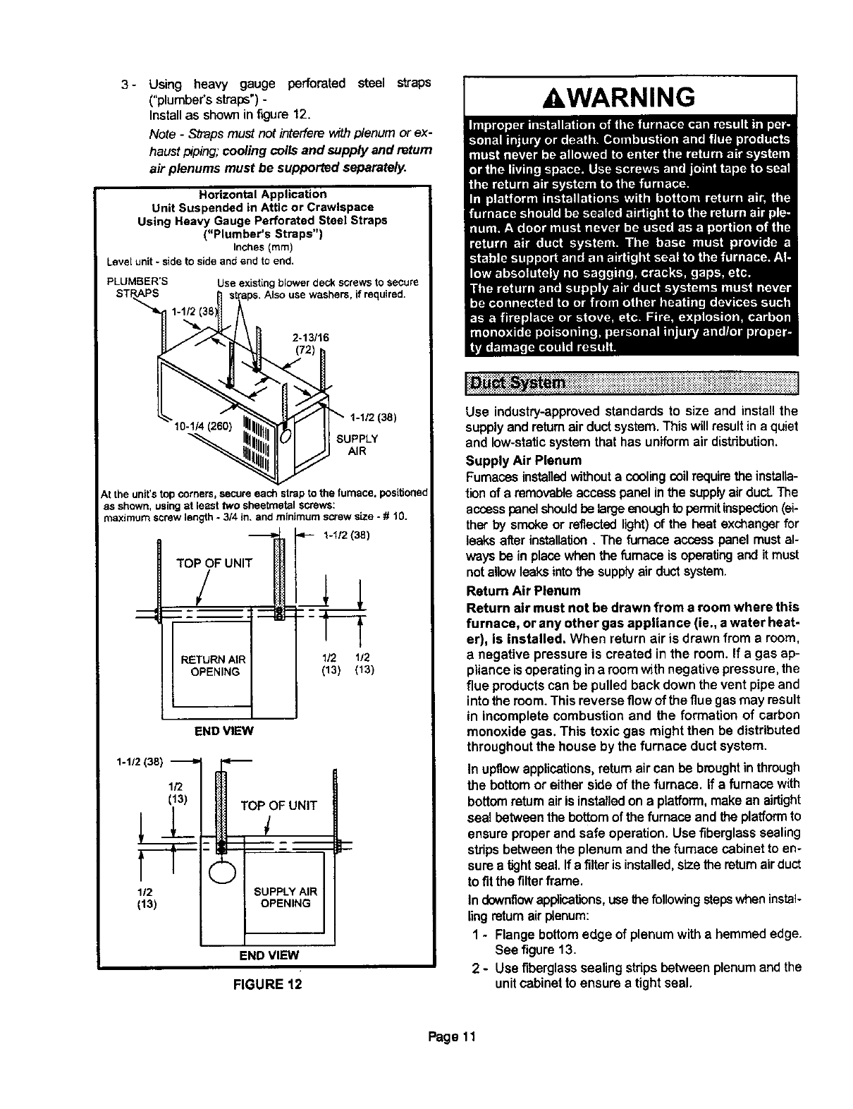
3- Using heavy gauge perforated steel straps
("plumber's straps') -
Install as shown in figure 12.
Note -Straps must not interfere withplenum or ex-
haust I_ping; cooling coils and supply and return
air plenums must be supported separately.
Horizontal Application
Unit Suspended in Attic or Crawlspace
Using Heavy Gauge Perforated Steel Straps
("Plumber's Straps")
Inches (ram)
Level unit - side to side and end to end.
PLUMBER'S Use existing blower deck screws to secure
Also use washers, if required,
2-13/16
1-1/2 (38)
SUPPLY
AIR
Atthe unit's top corners, secure each strap to the furnace, positJone_
as shown, using st least two sheetrnetal screws:
maximum screw length - 3/4 in. and minimum screw size - # 10.
1-1/2 {38)
TOP OF UNIT
/
RETURN AIR 112 1/2
OPENING (13) (13)
END VIEW
1-1/2 (3S)
1/2
(13) TOP OF UNIT
112 ;UPPLY AIR
(13) OPENING
END VIEW
FIGURE 12
Use industry-approvedstandards to size and installthe
supplyand rstumair ductsystem.This willresultina quiet
and low-staticsystemthat has uniformair distdbution.
Supply Air Plenum
Furnacesinstalledwithouta coolingcoilrequirethe instaUa-
tion of e removableaccesspanel inthe supplyairduct.The
accesspanelshouldbe largeenoughto permitinspection(ei-
ther by smoke or reflectedlight)of the heat exchangerfor
leaks after installation.The furnace access panel mustal-
waysbe in placewhen the furnace is operatingand it must
notallowleeksintothe supplyair ductsystem.
Return Air Plenum
Return air must not be drawn from a room where this
furnace, or any other gas appliance (ie., a water heat-
er), is installed. When return air is drawn from a room,
a negative pressure is created in the room. If a gas ap-
pliance is operating in a room with negative pressure, the
flue productscan be pulled back down the vent pipe and
into the room. This reverse flow of theflue gas may result
in incomplete combustion and the formation of carbon
monoxide gas. This toxic gas might then be distributed
throughout the house by the furnace duct system.
In upfiowapplications,returnair can be brought in through
the bottomor either side of the furnace. If afurnace with
bottomreturnairis installedon a platform,makean airtight
seal between the bottomof the furnace and the platformto
ensure proper and safe operation. Use fiberglasssealing
stripsbetweenthe plenumand the furnace cabinet to en-
sure a tightseal.If a filter is installed,sizethe returnair duct
to fit the filterframe.
In downfiow applications,usethe followingsteps when instal-
ling rstum air plenum:
1-Flange bottom edge of plenum with a hemmed edge.
See figure 13.
2 - Use fiberglass sealing strips between plenum endthe
unit cabinet to ensure a tight seal.
Page 11
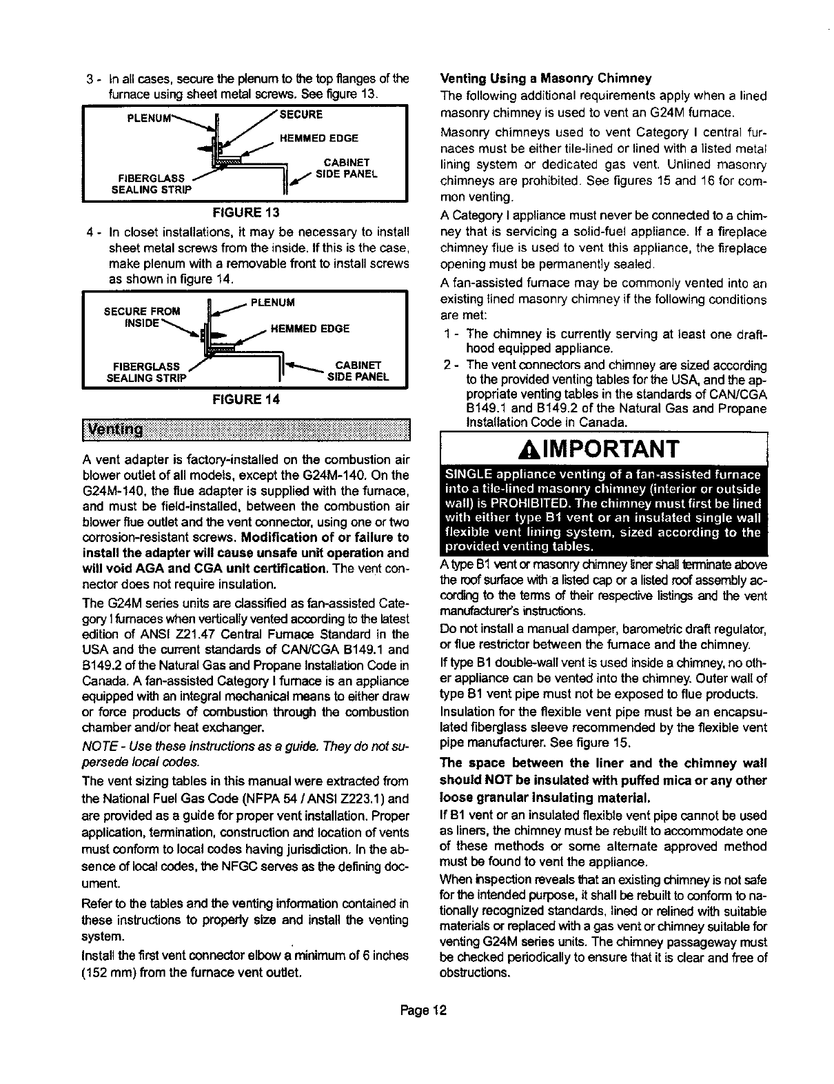
3- Inallcases,securetheplenumtothetop flanges of the
furnace using sheet metal screws.See figure 13.
PLENUM.._._ JSECURE
._ HEMMED EDGE
FIGURE 13
4 - In closet installations,it may be necessary to install
sheet metalscrews from the inside.Ifthis isthe case,
make plenumwitharemovablefront to installscrews
as shownin figure 14.
a _ PLENUM
SECURE FROM .jl_
,NSIDE_,_._ HEMMED EDGE
FIGURE t4
: ::_:i_:::_:::_::'::::iii%::_:.iiii::iiiiiiiiii'ii'::iiii ::ii_ii'ii_i::ii'i_=:i'==:i"i_i'i'i?i_i'iii_i;i_iii'i_i'i':.:iiiiii::%::i":::.i i:.i'
.V mg ...................................................................................................................................................................
Avent adapter is factory-installed on the combustion air
blower outlet of all models, except the G24M-140. On the
G24M-140, the flue adapter is supplied with the furnace,
and must be field-installed, between the combustion air
blower flueouUetand the vent connector, using one or two
corrosion-resistant screws. Modification of or failure to
install the adapter will cause unsafe unit operation and
will void AGA and CGA unit certification, The vent con-
nectordoes not require insulation.
The G24M sedes units are classified as fan-assisted Cate-
gory tfurnaces when vertically vented according to the btest
edition of ANSI Z21.47 Central Fumaca Standard in the
USA and the current standards of CAN/CGA B149.1 and
B149.2 of the Natural Gas and Propane Installation Code in
Canada. A fan-assisted Category I furnace is an appliance
equipped with an integral mechanical means to eitherdraw
or force productsof combustion through the combustion
chamber and/or heat exchanger.
NO TE -Use these instructions as eguide. They do not su-
persede local codes.
The vent sizingtables in this manual were extracted from
the National Fuel Gas Code (NFPA 54 /ANSI Z223.1 ) end
are provided as a guide for proper vent installation. Proper
application,termination, construction and location of vents
must conform to local codes having jurisdiction. In the ab-
sence of local codes,the NFGC servesas the definingdoc-
ument.
Referto the tablesand the ventinginformationcontained in
these instructionsto properlysize and installthe venting
system.
Installthe first ventconnectorelbowa'minimumof 6 inches
(152 ram) fromthe furnace vent outlet.
Venting Using a Masonry Chimney
The following additional requirements apply when a lined
masonry chimney is used to vent an G24M furnace.
Masonry chimneys used to vent Category I central fur-
naces must be either tile-lined or lined with e listed metal
lining system or dedicated gas vent. Unlined masonry
chimneys are prohibited. See figures 15 and 16 for com-
mon venting.
A Category I appliance must never be connected to achim-
ney that is servicing e solid-fuel appliance. If a fireplace
chimney flue is used to vent this appliance, the fireplace
opening must be permanently sealed.
A fan-assisted fumaca may be commonly vented into an
existing lined masonry chimney if the following conditions
are met:
1 - The chimney is currently serving at least one draft-
hood equipped appliance.
2 - The vent connectors end chimney are sized according
to the provided venting tables for the USA, and the ap-
propriate venting tables in the standards of CAN/CGA
B149.1 and B149.2 of the Natural Gas and Propane
Installation Code in Canada.
A type B1vent or mascnry chimney Itoershallterrninatsabove
the roofsurfacawithe listedcap or a listed roof assemblyac-
cordingto the terms of their respective listingsand the vent
manufacturer'sinstrucfions.
Do notinstalla manualdamper, barometric draft regulator,
or flue restdctor between the furnace and the chimney.
If type B1 double-wall vent is used insidee chimney, no oth-
er appliance can be vented into the chimney. Outer wall of
type B1 vent pipe must not be exposed to flue products.
Insulation for the flexible vent pipe must be an encapsu-
lated fiberglass sleeve recommended by the flexiblevent
pipe manufacturer. See figure 15.
The space between the liner and the chimney wail
should NOT be insulated with puffed mica or any other
loose granular insulating material.
If B1 vent or an insulated flexiblevent pipe cannot be used
as liners, the chimney must be rebuilt to accommodate one
of these methods or some alternate approved method
must be found to vent the appliance.
When inspection reveals that an existing chimney is not safe
for_e intended purpose, it shall be rebuilt to conform to na-
tionally recognized standards, linedor relined with suitable
materials or replaced with e gas vent or chimney suitablefor
venting G24M seriesunits. The chimney passageway must
be checked periodically to ensure that it is clear and free of
obstructions.
Page 12
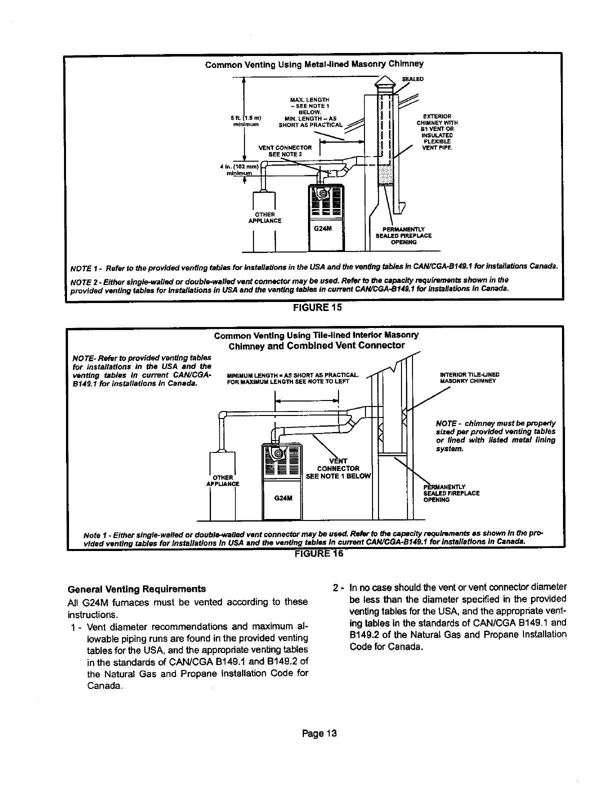
Common Venting Using Metal-lined Masonry Chimney
MAX. LENGTH
- SEE NOTE 1
BELOW,
4in, (102rmm) _'_
OTHER
APPLIANCE
i 1i
EXTERLOR
CHIMNEY WITH
I!11 <s,
PERMANENTLY
SEALED FIREPLACE
OPENING
NOTE 1 o Refer to the provided venting tables for installations in the USA and the venting tables in CAN/CGA.B149.1 for insfalletlons Canada
NOTE 2- Either single*watied or double.walled vent connector may be used. Refer to the capacity e_luirementa shown in the
provided venting tables for installations in USA end the venting tables in current CAN/CGA-B1411.1for Installations in Canada,
FIGURE 15
NOTE- Refer to provided venting tables
for installations in the USA and the
venting tables in current CAN/CGA-
B14g I for installations in Canada.
Common Venting Using Tile-tined Interior Masonry
Chimney and Combined Vent Connector
MiNiMUM LENGTH =AS SHORT AS PRACTICAL
FOR MAXIMUM LENGTH SEE NOTE TO LEFT
APPLIANCE
CONNECTOR
INTERIOR TILE-L] NED
MASONRY CHIMNEY
NOTE- chimney must be property
sized par provided venting tables
or lined with listed metal lining
system,
SEALED FIREPLACE
OPENING
Note1 - Eithersingle-walledordouble.walledventconnectormaybeused.Referto thecapacity requirementsas shownIn the pro-
videdventing tables for InstallationsIn USAand the ventingtables In currentCAN/CGA-B141l.ffor installationsin Canada,
FIGURE t6
General Venting Requirements
All G24M furnaces must be vented according to these
instructions.
1 - Vent diameter recommendations and maximum al-
lowable pipingruns are found inthe providedventing
tables forthe USA, and the appropriateventingtables
in the standards of CAN/CGA B149.1 and B149.2 of
the Natural Gas and Propane Installation Code for
Canada,
2-In nocase shouldthe vent or vent connectordiameter
be less than the diameter specifiedin the provided
ventingtablesfor the USA, andthe appropriatevent-
ing tables in the standardsof CAN/CGA B149.1 and
B149.2 of the Natural Gas and Propane Installation
Code forCanada,
Page 13
3 - For single appliance vents: If the vertical vent or tile-
lined chimney has a larger diameter or flow area than
the vent connector, use the vertical vent diameter to
determine the minimum vent capacity and the vent
connector diameter to determine the maximum
vent capacity. The flowarea of the vedicelvent,how-
ever, shall not exceed 7 times the flow area of the
listedappliancecategorizedvent area, drefthcodout-
let area or flue cellar area unlessdesignedaccording
to approved engineeringmethods.
4 - For multiple appliance vents: The flowarea of the larg-
estsectionof vertical vent or chimneyshallnotexceed
7 times the smallest listed appliancecetegefized vent
area, drafthoodoutlet area or flue collararea unless
designed according to approved engineering meth-
ods.
5 - The entire length of single wall metal vent connector
shall be readily accessible for inspection, cleaning,
and replacement.
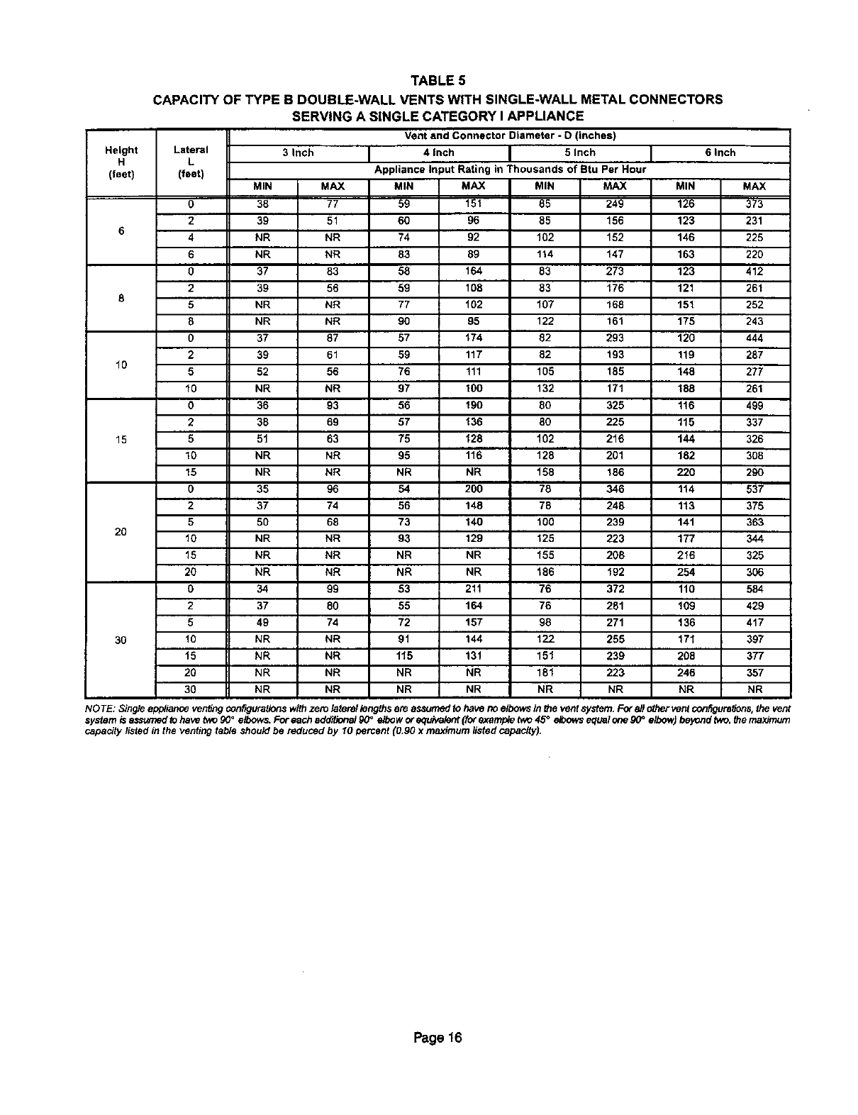
6 - Single appliance venting configurations with zero lat-
eral lengths, see tables 4 and 5, are assumed to have
no elbows in the vent system. For all other vent config-
urations, the vent system is assumed to have two 90°
elbows. For each additional 90° elbow or equivalent
(for example two 45° elbows equal one 90°elbow) be-
yond two, the maximum capacity listed in the venting
table should be reduced by 10 percent (0.90 x maxi-
mum listed capacity).
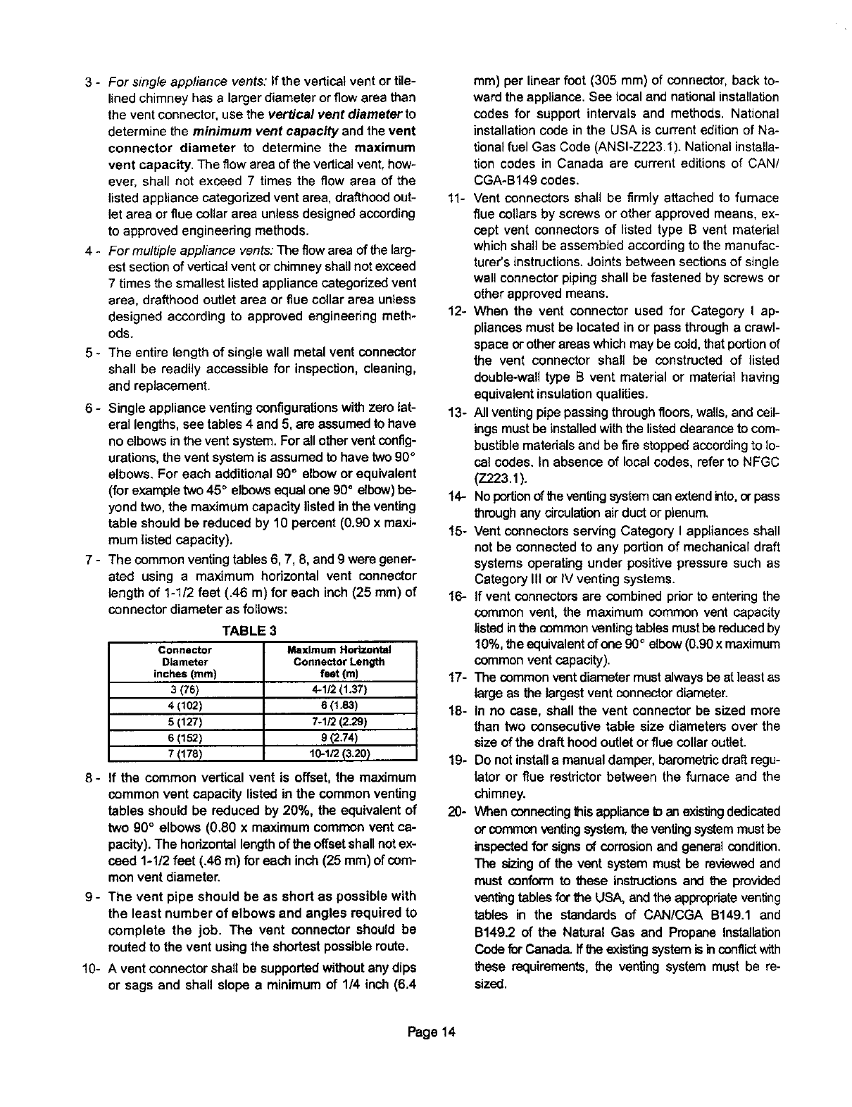
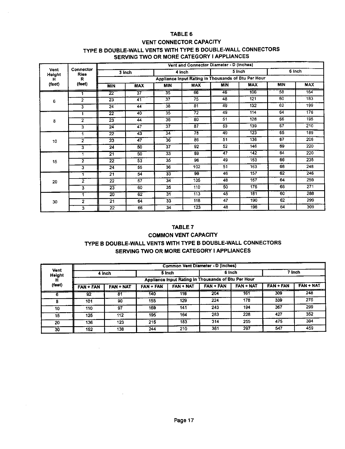
7 - The common venting tables 6, 7, 8, and 9 were gener-
ated using a maximum hodzontal vent connector
length of 1-1/2 feet (.46 m) for each inch (25 ram) of
connector diameter as follows:
TABLE 3
Connector
Diameter
inches (ram)
3(76)
4(102)
5 (127)
s(152)
7 (178)
Maximum Horizontal
Connector Length
feet (m)
4-1/2 (1.37)
s (1.e3)
7-tr2(2.29)
8 (2.74)
10-1/2 (3.20}
8 - If the common vertical vent is offset,the maximum
common vent capacity listed in the common venting
tables should be reduced by 20%, the equivalent of
two 90° elbows (0.80 x maximum common vent ca-
pacity). The hodzontal length of the offset shallnot ex-
ceed 1-1/2 feet (.46 m) for each inch (25 ram) of cem-
mon vent diameter.
9- The vent pipe should be as short as possible with
the least number of elbows and angles required to
complete the job. The vent connector should be
routed to the vent using the shortest possible route.
10- A vent connector shall be supported without any dips
or sags and shall slope aminimum of 1/4 inch (6.4
ram) per linear foot (305 mm) of connector, back to-
ward the appliance. See local and national installation
codes for support intervals and methods. National
installation code in the USA is current edition of Na-
tional fuel Gas Code (ANSI-Z223.1). National installa-
tion codes in Canada are current editions of CAN/
CGA-B149 codes.
11- Vent connectors shall be firmly attached to fumace
flue collars by screws or other approved means, ex-
cept vent connectors of listed type B vent material
which shall be assembled according to the manufac-
turer's instructions. Joints between sections of single
wall connector piping shall be fastened by screws or
other approved means.
12- When the vent connector used for Category I ap-
pliances must be located in or pass through a crawl-
space or other areas which may be cold, that portion of
the vent connector shall be constructed of listed
double-wall type B vent material or matedal having
equivalent insulation qualities.
13- All venting pipe passingthrough floors, walls, and ceil-
ings must be installed with the listed clearance to com-
bustible materials and be fire stopped according to lo-
cal codes. In absence of local codes, refer to NFGC
(Z223.1).
14- No portionof the venting system can extendinto,or pass
through any circulation air duct or plenum.
15- Vent connectors serving Category I appliances shall
not be connected to any portion of mechanical draft
systems operating under positive pressure such as
Category III or IV venting systems.
16- If vent connectors are combined prior to entering the
common vent, the maximum common vent capacity
listed inthe common venting tables must be reduced by
10%, the equivalent of one 90°elbow (0.90x maximum
common vent capacity).
17- The common vent diameter must always be at leastas
large as the largest vent connector diameter.
18- In no case, shall the vent connector be sized more
than two consecutive table size diameters over the
size of the draft hood outlet or flue collar outlet.
19- Do not install a manual damper, barometric draft regu-
lator or flue restdctor between the furnace and the
chimney.
20- When connecting this appliance toan existingdedicated
or common venting system,the venting system must be
inspected for signs of corrosion and general condition.
The sizing of the vent system must be reviewedand
mast conform to these instructions and the provided
venting tables for the USA, and the appropriate venting
tables in the standards of CAN/CGA B149.1 and
B149.2 of the Natural Gas and Propane Installation
Code for Canada. If the existing system is inconflictwith
these requirements, the venting system must be re-
sized.
Page 14
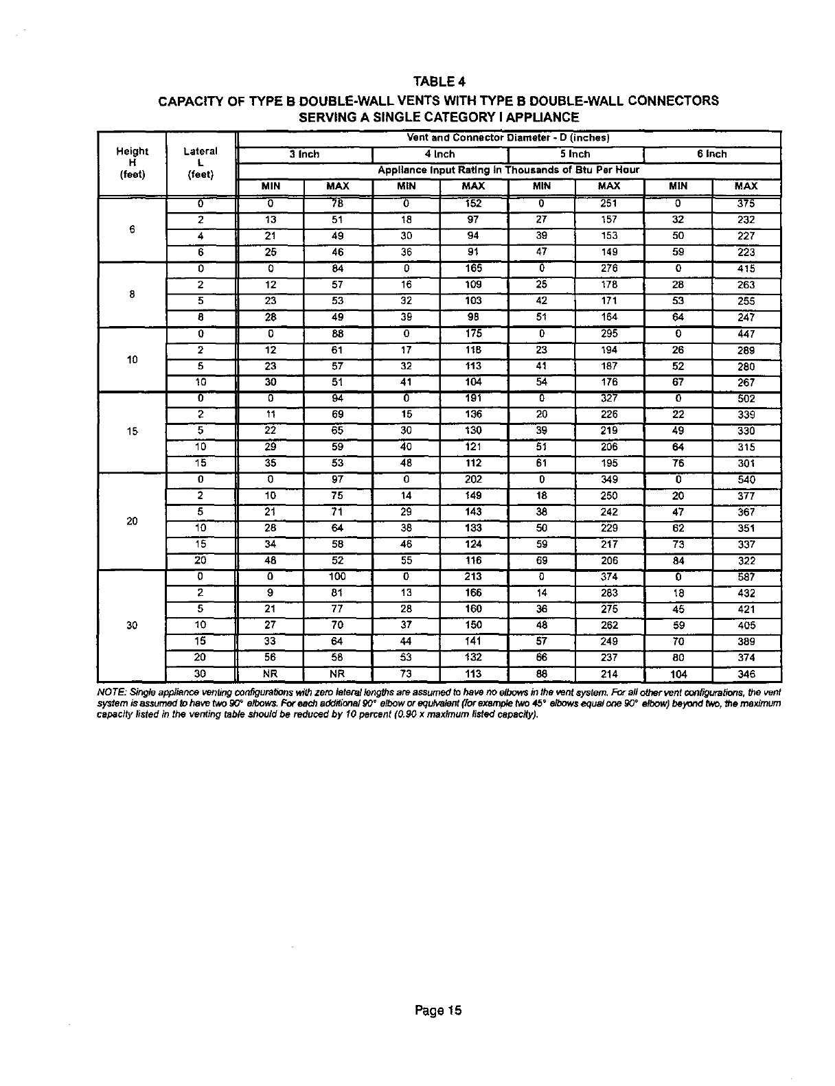
TABLE4
CAPACITY OF TYPE B DOUBLE-WALL VENTS WITH TYPE B DOUBLE-WALL CONNECTORS
Height Lateral
H L
(feat) (feet)
0
2
64
6
0
2
85
8
0
2
10 5
10
0
2
15 5
10
15
0
2
5
2O 10
15
20
0
2
5
30 10
15
2O
3O
MIN
0
13
21
25
0
12
23
28
0
12
23
30
0
11
22
29
35
0
10
21
28
34
48
0
9
21
27
33
56
NR
SERVING A SINGLE CATEGORY I APPUANCE
Vent and Connector Diameter - D (inches)
3 Inch 4 Inch I5 Inch
m
Appliance Input Rating In Thousands of Btu Par Hour
MAX
78
51
49
46
84
57
53
49
88
61
57
51
94
69
65
59
53
97
75
71
64
58
52
100
81
77
70
64
58
NR
MIN
0
18
3O
36
0
16
32
39
0
17
32
41
0
15
30
4O
48
0
14
29
38
46
55
0
13
28
37
44
53
73
MAX
152
97
94
91
165
109
103
98
175
118
f13
104
191
136
130
121
112
202
149
143
133
124
116
213
166
160
150
141
t32
113
MIN
0
27
39
47
0
25
42
51
0
23
41
54
0
20
39
51
61
0
18
38
5O
59
69
0
14
36
48
57
66
88
MAX
251
157
153
149
276
178
171
164
295
194
187
176
327
226
219
206
195
349
250
242
229
217
2O6
374
283
275
262
249
237
214
6 Inch
MIN
0
32
50
59
0
28
53
64
O
26
52
67
0
22
49
64
76
0
20
47
62
73
84
0
18
45
59
70
8O
104
MAX
375
232
227
223
415
263
255
247
447
289
280
267
502
339
330
315
301
540
377
367
351
337
322
587
432
421
405
389
374
346
NOTE: Singleapp/isnceventingconfiguraUonsv_Lhzero thtera/ton rutsare assumedtohave no elbow_in theventsystem,Forall otherventconfigurations,the vent
systemisassumed_ohave two90_elbows,Forea_ addifiona/90°elbowor equivalent(forexampletwo45°elbowsequalonegO° elbow) beyondP_o,themaximum
capacitylistedin the venting tableshouldbe reducedby 10 percent(0.90 x maximumlistedcapacity).
Page 15
Height
H
(feet)
10
15
20
30
TABLE 5
CAPACITY OF TYPE B DOUBLE-WALL VENTS WITH SINGLE-WALL METAL CONNECTORS
Lateral
L
(feet)
0
2
4
6
0
2
5
8
0
2
5
10
0
2
5
10
15
O
2
5
10
15
20
0
2
5
lO
15
20
30
MIN
38
39
NR
NR
37
39
NR
NR
37
39
52
NR
36
38
51
NR
NR
35
37
5O
NR
NR
NR
34
37
49
NR
NR
NR
NR
SERVING A SINGLE CATEGORY I APPLIANCE
Vent and Connector Diameter - D (inches)
3 Inch 4 Inch 5 Inch
Appliance Input Rating in Thousands of Btu Per Hour
MAX
77
51
NR
NR
83
56
NR
NR
87
61
56
NR
93
69
63
NR
NR
96
74
68
NR
NR
NR
99
80
74
NR
NR
NR
NR
MIN
59
6O
74
83
58
59
77
90
57
59
76
97
56
57
75
95
NR
54
56
73
93
NR
NR
53
55
72
91
115
NR
NR
MAX
151
96
92
89
164
108
102
95
174
117
111
100
190
136
128
116
NR
200
148
140
129
NR
NR
21t
164
157
144
131
NR
NR
MIN
85
85
102
114
83
83
107
122
82
82
105
132
80
8O
102
128
158
78
78
100
125
155
186
76
76
98
122
151
181
NR
MAX
249
156
152
147
273
176
168
161
293
193
185
171
325
225
216
201
186
346
248
239
223
208
192
372
281
271
255
239
223
NR
6 Inch
MIN
126
123
146
163
123
121
151
175
120
119
148
188
116
115
t44
182
220
114
113
141
177
216
254
110
109
136
171
208
246
NR
MAX
373
231
225
220
412
261
252
243
444
287
277
261
499
337
326
3O8
29O
537
375
363
344
325
306
584
429
417
397
377
357
NR
NOTE: Singleapp4ianoaver_ngconfigurationswithzero laterallengthsare assumedto havenoelbowsin the ventsystem.Forall othervent_figura_ons, the vent
ao
system isassumedtohavetwo90 eibow,_Fo_each ad_N_al _0°elboworequtva_t (f_ exampleIwo45 etoowsequalonegO=elbowJbeyondtwo.themaximum
capacitylistedin the ventingtable shouldbe reduced by 10 percent(0.90 x maximumlistedcapaclty_.
Page 16
Vent
Height
H
(feet)
6
8
10
t5
20
30
TABLE 6
VENT CONNECTOR CAPACITY
TYPE B DOUBLE-WALL VENTS WITH TYPE B DOUBLE-WALL CONNECTORS
Connector
Rise
R
(feet)
1
2
3
1
2
3
1
2
3
1
2
3
1
2
3
1
2
3
SERVING TWO OR MORE CATEGORY I APPLIANCES
MIN
22
23
24
22
23
24
22
23
24
2t
22
24
21
22
23
20
21
22
3 inch
MAX
37
41
44
40
44
47
43
47
50
50
53
55
54
57
6O
62
64
66
Vent and Connector Diameter - D (inches)
4 inch I 5 Inch
B
Appliance Input Rating in Thousands of Btu Per Hour
MIN
35
37
38
35
36
37
34
36
37
33
35
36
33
34
35
31
33
34
MAX MIN MAX
66 46 106
75 48 121
81 49 132
72 49 114
80 51 128
87 53 139
78 49 123
86 51 136
92 52 146
89 47 142
96 49 153
102 51 163
g9 46 157
105 48 167
110 50 176
113 45 181
118 47 190
123 48 198
MIN
58
60
62
64
66
67
65
67
69
64
66
68
62
64
66
6O
62
64
6inch
MAX
164
183
199
176
195
210
189
206
220
220
235
248
246
259
271
288
299
309
Vent
Height
H
(feet)
6
8
10
15
20
3O
TABLE 7
COMMON VENT CAPACITY
TYPE B DOUBLE-WALL VENTS WITH TYPE B DOUBLE-WALL CONNECTORS
SERVING TWO OR MORE CATEGORY I APPLIANCES
4 Inch
FAN+ FAN FAN+NAT
92 81
101 90
110 97
125 112
136 123
t52 138
Common Vent Diameter - D (Inches)
5 Inch 6 Inch 7 Inch
Appliance Input Rating in Thousands of Btu Per Hour
FAN + NAT
116
129
141
164
183
210
FAN + FAN
204
224
243
283
314
361
FAN + NAT
161
178
194
228
255
297
FAN ÷ FAN
3O9
339
367
427
475
547
FAN +FAN
140
155
169
195
215
244
FAN+NAT
248
275
299
352
394
459
Page 17
Vent
Height
H
(feet)
15
3O
TABLE 8
VENT CONNECTOR CAPACITY
TYPE B DOUBLE-WALL VENTS WITH SINGLE-WALL METAL CONNECTORS
Connector
Rise
R
(feet)
1
2
3
1
2
3
1
2
3
SERVING TWO OR MORE CATEGORY I APPLIANCES
MIN
NR
NR
NR
NR
NR
NR
47
5O
54
3 Inch
MAX
NR
NR
NR
NR
NR
NR
6O
62
84
Vent and Connector Diameter - D (inches)
4 Inch 5 inch
Appliance Input Rating in Thousands of Btu Per Hour
MIN
NR
NR
NR
79
83
87
77
81
85
MAX MIN MAX
NR NR NR
NR NR NR
NR 121 131
87 116 138
94 121 150
100 127 160
110 113 175
115 117 185
119 122 193
MIN
NR
168
174
177
185
193
169
177
185
6Inch
MAX
NR
182
198
214
230
243
278
290
30O
Vent
Height
H
(feet)
6
8
10
15
2O
3O
TABLE 9
COMMON VENT CAPACITY
TYPE B DOUBLE-WALL VENTS WITH SINGLE-WALL METAL CONNECTORS
SERVING TWO OR MORE CATEGORY I APPLIANCES
Common Vent Diameter * D (inches)
4 inch
FAN+ FAN FAN + NAT
89 78
98 87
106 94
121 108
131 118
145 132
5 inch 6 Inch
Appliance Input Rating in Thousands of atu Per Hour
FAN + FAN
136
151
163
189
208
236
FAN + NAT
113
126
137
159
177
202
FAN + FAN
200
218
237
275
305
350
FAN ÷ NAT
158
173
189
221
247
286
FAN ÷ FAN
304
331
357
416
463
533
7Inch
FAN + NAT
244
269
292
343
383
446
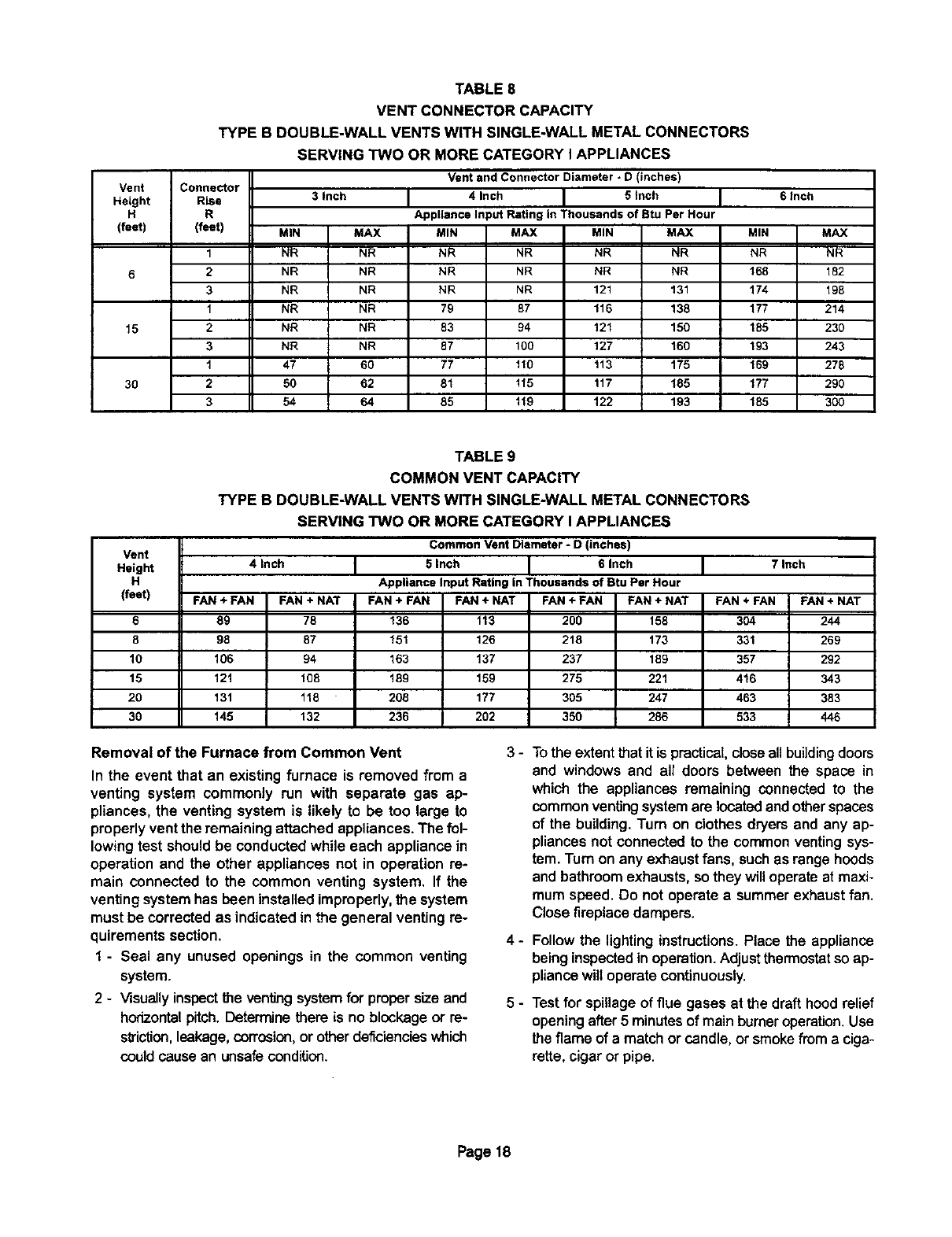
Removal of the Furnace from Common Vent
In the event that an existing furnace is removed from a
venting system commonly run with separate gas ap-
pliances, the venting system is likely to be too large to
properly ventthe remaining attached appliances. The fol-
lowing test shouldbe conducted while each appliance in
operation and the other appliances not in operation re-
main connected to the common venting system. If the
venting systemhas been installed improperly,the system
must be corrected as indicated in the general venting re-
quirements section.
1- Seal any unused openings in the common venting
system.
2-Visuallyinspectthe ventingsystemfor propersizeand
horizontal pitch. Deterrrmethere is no blockage or re-
striction, leakage,corrosion, or other deficiencies which
could cause an unsafe condition.
3-
4-
5-
Tothe extentthat it is practical, closeallbuilding doors
and windows and all doors between the space in
which the appliances remaining connected to the
common ventingsystemare located andotherspaces
of the building. Turn on clothes dryers and any ap-
pliancesnot connected to the commonventingsys-
tem. Turn on any exhaust fans, suchas range hoods
and bathroom exhausts, sothey willoperate at maxi-
mum speed. Do not operate a summerexhaustfan.
Close fireplacedampers.
Follow the lightinginstructions. Place the appliance
being inspected in operation. Adjust thermostat so ap-
pliance will operate continuously.
Test for spillage of flue gases at the draft hood relief
openingafter 5 minutesof mainburner operation.Use
the flame of a match orcandle, or smokefrom a ciga-
rette,cigar or pipe.
Page 18
6- Afterdetermining that each appliance remaining con-
nected to the common venting system prepedy vents
when tested as indicated in step 3, return doors, win-
dows, exhaust fans, fireplace dampers and any other
gas-burning appliance to their previous condition of
use.
7- If improper venting is observed during any of the
above tests, the common venting system must be cor-
rected. The common venting system should be re-
sized to approach the minimum size as determined by
using the appropriate tables in appendix G in the cur-
rent standards of the National Fuel Gas Code ANSI
Z223.1 in the USA, and the appropriate Category 1
Natural Gas and Propane appliances venting sizing
tables in the current standards of the CAN/CGA
B149.1 and B149.2 in the Natural Gas and Propane
Installation Code in Canada.
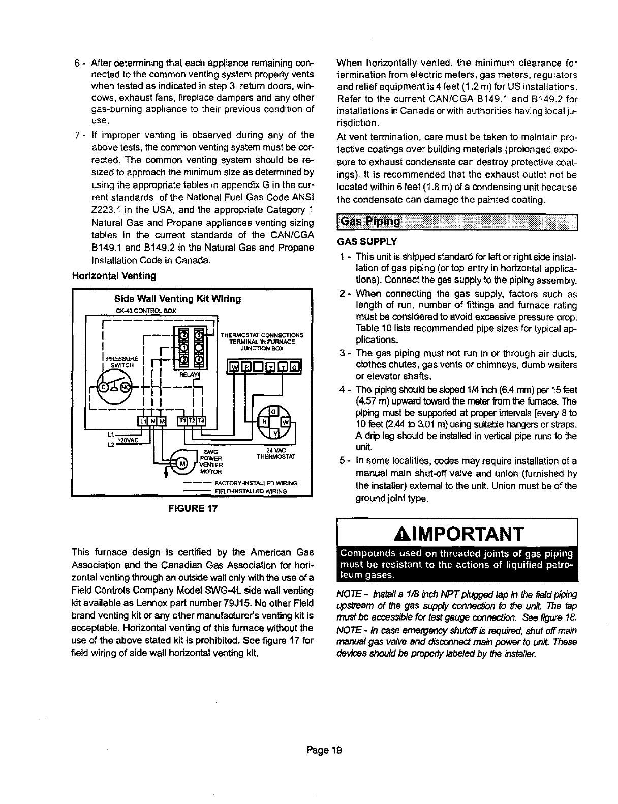
Horizontal Venting
Side Wall Venting Kit Widng
CX_3 CONTROL 8OX
MOTOR
THERMOSTAT CONNECTIONS
13ERMINAL IN FURN&CE
JUNC'RQN BOX
24 VAC
THERMC_TAT
.... FA_Y4NST_ED WI_NG
-- FIFJ.D-INSTALLED WIRING
FIGURE 17
This furnace design is certified by the American Gas
Association and the Canadian Gas Association for hori-
zontal venting through an outside wall only with the use of a
Field Conb'ols Company Model SWG-4L sidewall venting
kit available as Lennox part number 79J15. No other Field
brand venting kit or any other manufacturer's venting kit is
acceptable. Horizontal venting of this furnace without the
use of the above stated kit is prohibited. See figure 17 for
field wiring of side wall horizontal venting kit,
When horizontally vented, the minimum clearance for
termination from electric meters, gas meters, regulators
and relief equipment is 4 feet (1.2 m) for US installations.
Refer to the current CAN/CGA B149.1 and B149.2 for
installations in Canada or with authorities having localju-
risdiction.
At vent termination, care must be taken to maintain pro-
tective coatings over building materials (prolonged expo-
sure to exhaust condensate can destroy protective coat-
ings). It is recommended that the exhaust outlet not be
located within 6 feet (1.8 m) of a condensing unit because
the condensate can damage the painted coating.
Iiiiiiii_i_ii_lii!ii::i!iiiiii iii {iiil!i¢i!iiiTiiiiT{iiii!iiiiiiii{ii
GAS SUPPLY
1 - This unitisshipped standardfor left orright sideinstal-
lation of gas piping (or top entry in horizontal applica-
tions). Connect the gas supply to the piping assembly.
2- When connecting the gas supply, factors such as
length of run, number of fittings and furnace rating
must be considered to avoid excessive pressure drop.
Table 10 listsrecommendedpipe sizes for typicalaP-
plications.
The gas piping must not run in or throughair ducts,
clothes chutes, gas vents or chimneys,dumbwaiters
or elevator shafts,
3-
4-
5-
The pipingshould besloped 1/4 inch(6.4 ram) per 15feet
(4.57 m) upwardtowardthe meterfrom the fumace.The
piping must be supported at proper intervals [every 8 to
10 feet(2.44to 3.01 m) using suitablehangers or straps.
A drip leg should be installedin verUcalpipe runs to the
unit.
In some localities,codes may require installationof a
manuel main shut-off valve and union (furnished by
the installer) externalto the unit. Union must be of the
groundjointtype.
AIMPORTANT
NOTE -Install a 1/8 inch NPT plugged tap in the _eldpiping
u_m of _e gas supplyconnes_on_ the unit. The tap
must be accessiblefor testgaugeconnection._ee figure 18.
NOTE -In case emergencyshutoffis required, shutoff main
manual gas valve and disconnect main power to uniL These
devicesshou/d be propedylabeled by the installer.
Page 19
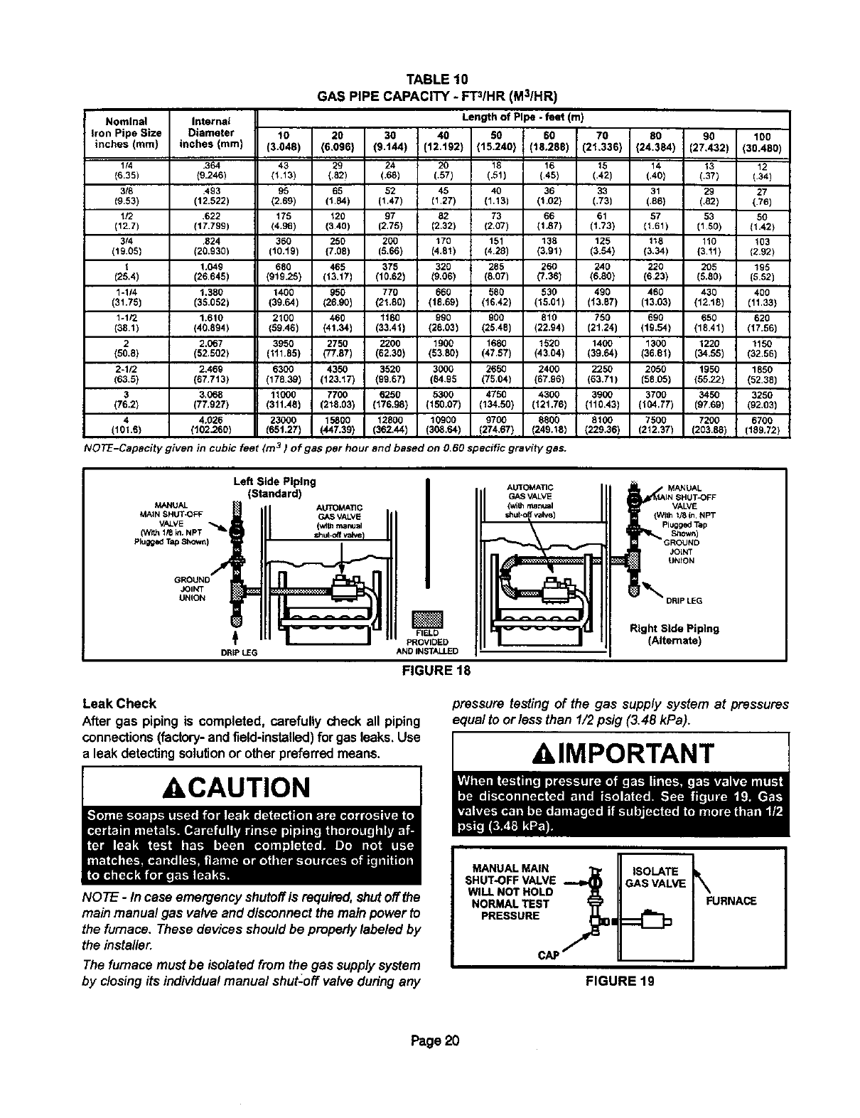
TABLE 10
GAS PIPE CAPACITY - FT3/HR (M3/HR)
Nominal Internal
Iron Pipe Size Diameter 10 20 30 i 40
inches (mm) inches (mm) (3.048) (6.096) (9.144) I (12.192
1/4 .364 43 29 24 20
(6.35) (9.246) (1113) (.52) (,65) (.57)
3/8 .493 96 65 52 45
(9.53) (12.522) (2.69) (t.84) (1.47) (1.27)
112 .622 175 t20 97 82
(12.7) (17.799) (4.95) (3.40) (2,75) (2.32)
3/4 .524 360 250 200 170
(19.05) (20.930) (10.t9) (7.08) (5,66) (4,81)
1 1.049 680 465 375 320
(25,4) (26.645) (919.25) (13.t7) (10.62) (9,06)
1-1/4 1,380 1400 950 770 660
(31.75) (38.052) (39.64) (26,90) (21.80) (18.69)
1-1/2 1.610 2100 460 tt80 990
(38,1) (40.894) (59A6) (41.34) (33,41) (26,03)
2 2,067 3950 2750 2200 1900
(50.8) (52.502} (111.85) (77,67) (62,30) (53,80)
2-1/2 2,469 6300 4350 3520 3000
(63,5) (67.713) (176.39) (123,17) (99.67) (84.95
3 3,068 11000 7700 6250 5300
(76.2) (77.927) (311.46) (216.03) (176.98) (150.07)
44.026 23000 15800 12800 10900
(101.6) (102.260) (65t.27) (447.39) (362,44) (308.64)
Length of Pipe -feet (m)
80 60 70 00 90 100
(15.240) (18.288) (21,336) (24.384) (27,432) (30.480)
18 16 15 14 13 12
(.51) (.45) (.42) (,40) (.37) (.34)
40 36 33 31 29 27
(1.13) (1.02) (.73) (.88) (,82) (.76)
73 66 61 57 53 50
(2.07) (1,87) (I,73) (1.61) (150) (1.42)
151 138 125 118 110 103
(4.28) (3.91) (3.54) (3,34) {3.11) (2.92)
285 260 240 220 205 195
(8,07) (7.36) (6.80) (623) (5.80) (5.52)
580 530 490 460 430 400
(16.42) (15.01) (13.87) (13.03) (12.18) (11.33)
900 810 750 690 650 620
(25,48) (22.94) [21.24) (19,54) (18.41) (17.56)
1680 1520 1400 1300 1220 1150
(47.57) (43,04) (39.64) (36,01) (34.55) (32,56)
2650 2400 2250 2050 1950 1850
(75.04) (67.96) (63.71) (58.05) (55,22) (52.38)
4750 4300 3900 3700 3450 3250
(134.50) (121.76) (110.43) (104.77) (97.69) (92.03)
9700 8600 8100 7500 7200 6700
(274,67) (249.13) (229,36) (212,37) (203,88) (189.72)
NOTE-Capacity given 3in cubic feet (m )of gas per hour and based on O,6Ospecific grav_ty gas.
MANUAL
MAIN SHUT-OFF
VALVE
(With I/6 _n.NPT "_I
Plugged Tap Shown)
JOINT
UNION
Left Side Piping
(Standard)
AUTOMATIC
GASVALVE
(v_t=manual
DRIPLEG
AUTOMATIC
GASVALVE
(withmanusl
valvai
FIELD
PROVIDED
AND INSTALLED
FIGURE 18
MANUAL
VALVE
Plugged Tap
Shown)
JOLNT
UNtON
_DRIP LEG
Right Side Piping
(Alternate)
Leak Check
After gas piping is completed, carefully check all piping
connections(factory-andfield-installed) forgas leaks.Use
a leak detectingsolutionor other preferred means.
ACAUTION
NOTE -In case emergency shutoff is required,shutoffthe
main manual gas valve and disconnect the mainpowerto
the furnace. These devicesshould be properly labeledby
the installer.
The furnacemust be isolatedfrom the gas supplysystem
by closingits individualmanual shut-off valve duringany
pressure testing of the gas supply system at pressures
equal to or/ess than 1/2 psig (3.48 kPa).
AIMPORTANT
MANUAL MAiN
SHUT,OFF VALVE
WILL NOT HOLD
NORMAL TEST
PRESSURE
c/_
ISOLATE
FIGURE 19
Page 20
l[l_[_i[_l i ii{iliiiiiii[iii{ii{ii}i{iiii{iiiiii}!{}i{ii{ii{i{{}i{iii}iiii{{i{i}ili{i}{i!{iI
ACAUTION
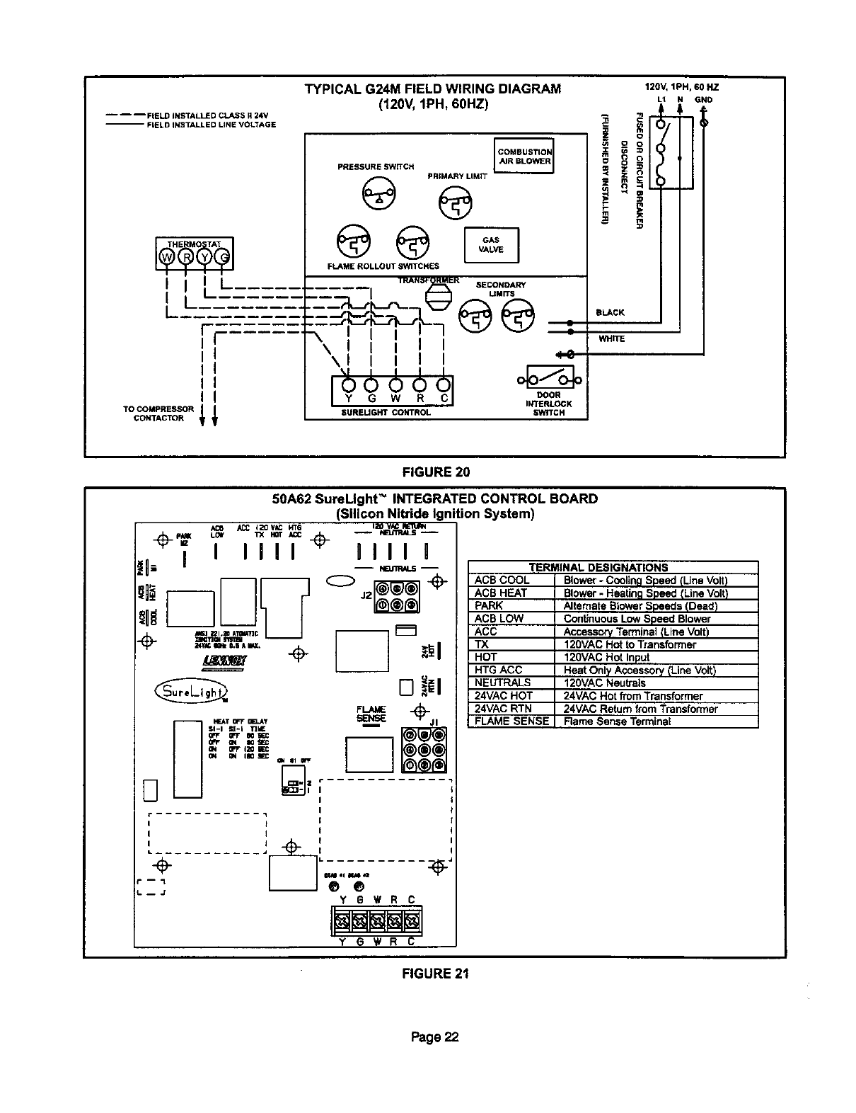
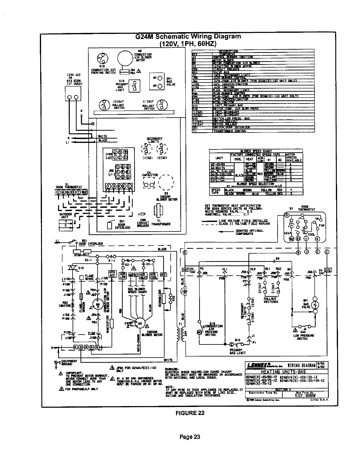
These units operate on 120 volt, single phase, 60 hz
electrical power. Refer to figure 20 for field wiring and
figure 22 for schematic wiring diagram and trouble-
shooting.
1 - Select circuit protection and wire size according to the
unit rating plate.
2 - Knockouts are provided on both sides of the fumaca
cabinet to facilitate widng.
3 - install the room thermostat according to instructions
provided with the thermostat.
4 - install aseparate disconnect switch (protected by ei-
ther fuse or circuit breaker) near the unit so power can
be turned off for servicing.
5 - Before connectJng the thermostat or the power widng,
check to make sure the wires will be long enough to
facilitate servicing at a later date. Remove the blower
access panel and open the panel to check wirelength
for access.
6 ° Complete wiring connectionsto the equipment using
wiringdiagram providedwithunit andwidngdiagrams
shown infigures 20 and 22. Use 18 gaugewire or larg-
er for thermostatconnections.
7 - Electricallygroundthe unit accordingto local codes or,
in the absence of local codes, according to the current
National Electric Code (ANSI/NFPA No. 70) for the
USA and current Canadian Electric Code part 1 (CSA
standard C22,1) for Canada.
NO TE- The G24M furnace contains electronic com-
ponents that are polarity sensitive. Make sure that
the furnace is wired correctly and is properly
grounded.
8 - One tine voltage accessory "ACC" terminal is provided
on the furnace control board with aprotective plastic
cap. Any accessory rated up to 4 amps can be con-
nected to this terminal(after removing the protective
cap) with the neutral leg of the circuitbeing connected
to the line voltage neutral wire. See figure 21 for con-
trol board configuration. This terminal is energized
whenever the blower is in operation.
9 - One line voltage heating accessory"HTG ACC" termi-
nal is provided on the fumaco control board with a pro-
tective plastic cap. Any accessory rated up to 4 amps
can be connectedto this terminal (after removing the
protective cap) with the neutral leg of the circuit being
connected to the line voltage neutral wire. See figure
21 for control board configuration. This terminal is en-
ergized in the heating mode whenever the blower is in
operation.
Indoor Blower Speeds (Refer to Figure 22)
1-When the thermostat is set to "FAN ON", the indoor
blowerwill runcontinuouslyon low speedwhen there
is no coolingor heatingdemand.
2 - When the G24M is running inthe heatingmode, the in-
doorblowerwillrun on the heatingspeed.
3 - When there is a coolingdemand,the indoorblowerwill
run on the coolingspeed.
Page 21
TYPICAL G24M FIELD WIRING DIAGRAM
(120V, 1PH, 60HZ)
-- -- -- FIELD iNSTALLED CLASS I124V
-- FIELD INSTALLED LiNE VOLTAGE
THE MO TAT
I
I
I
I
I
PRESSURE SWITCH @
PRIMARY LIMIT
@ ®
FLAME ROLLOUT SWITCHES
I I
II
Y G W R
8UREUGHT CONTROL
SECONOARY
UMrrS
@@ a
4_
DOOR
INTERLOCK
_NrrCH
120V,1PH,60 HZ
L1 GNO
i '
BLACK
WHITE
FIGURE 20
50A62 SureLIght _INTEGRATED CONTROL BOARD
(Silicon Nltride Ignition System)
÷,=- _, _ "=,=÷-- .__
0_ I I I II 0Ill1
-- NEJ_AI._ --
SI-I Iii-I 'rIME m
G'I QN II0 _ fIN III If'p"
i
iI
=. .... J
L. ...........
II
JYEW R C
YG WR C
TERMINAL DESIGNATIONS
ACB COOL
ACB HEAT
PARK
ACB LOW
ACC
TX
HOT
HTG ACC
NEUTRALS
24VAC HOT
24VAC RTN
FLAME SENSE
Blower - Cooling Speed ILlne Volt)
Blower -Heating Speed (Line Volt)
Alternate Blower Speeds (Dead)
ContinuousLow Speed Blower
Accessory Terminal (Line Volt)
120VAC Hot to Transformer
120VAC Hot Input
Heat Only Accessory (Line Volt)
120VAC Neutrals
24VAC Hot from Transformer
24VAC Return from Transformer
Rame Sense Terminal
FIGURE 21
Page 22
IZoV
OR
Nm
LI"_''"'b_ J,
G24M Schematic Wiring Diagram
(120V, 1PH, 60HZ)
_._,,_ _;_ __
I
SiO _
LIU_T
IZlS47 (13147
U_lrITS1 _IrZTC_ 1
|
SECgI_ff
LIMITS
&,
11)_1 121521
r--'l /\
III I
?_q; , ,
B3
-_ II "_
/j.
-ff ClRI_JIT Tp./_ISFORKER
1 OWa/_Bq
,,-_.L. .,..L :T
S_T _AT HEAT A_rlCIPAT,0N ROOM
FO_ I_ld SLclqIESLimITSb.S 4_L.LO_, $1 _AT
NF,4ITI_HO_RS t/ALOE... 0.5
VALISE..... 0.7
LINE "_-TA_ FIELD II_TALLI_
.... CLASS 11 Y_I.TA_ FIELD WllqlN6
0_40T1_ OPTIO_d-
TI _COk_l O_ i_
,_ [III_MI"- _ZC S40_ HADIID,CAH CAb_ INJUR'r
TO PRE_IT HOT_ BLR4OLR, QRDF_IH.LINIT KIST IE _IN _OR_U4CIE
I_=_'1__0f414£_ _ _ ,_ III I 12 ARE _ _l'r;4 NATIQN/L id40 LIO¢,_*.CLOGS.
Gb_ _dOT_ _ 10 A_Y "n_dIffiUJ.ALL _MOTOR
ONE I_IECT ION N_-'T _1_PiC_KEOOr#il OR MZ*
,_ FDRPRQP.M4FJLp M_.y NOTE-
IF ANY _IRE IN 1Tllli /_PLIM, I¢_ IS F_wz,J_Cl_,[T
ii_ _AEFU,I_ _TH 111_E0F LIKE SIZ£
RATll4O b4_ II4_q.ATIOH "IHICXI4_S.
FIGURE 22
Page 23
iU_tiS_U_!_i_i_iiii!i_ii!i_i_i_i_i_i_i_iiiii_i_i_i_i_i_:i_i_i_i_i_i_i_i_i_i_i_ii_ii_iiii!i_iiiii_iii_ii_i_i_}_i_i_i_i_i_i_iii_i_i_i_i_iii_i
,WARNING
&WARNING
,CAUTION
FOR YOUR SAFETY READ BEFORE LIGHTING
BEFORE LIGHTING smell all around the appliance areafor
gas. Be suretosmell next to the floorbecause some gas is
heavier than air and will settleon the floor.
Use onlyyour hand to turn the gas controlknob.Neveruse
tools.Ifthe knobwillnot turnby hand,donot _3_to repairit,call
a qualifiedservicetechnician.Force or attemptedrepairmay
resultin afire or explosion.
Placing Furnace Into Operation
G24M furnaces are equipped with a SureUght" ignition
system. Do not attemptto manuallylightburnerson these
furnaces. Each time the thermostatcallsfor heal the bum-
ere will automaticallylight.
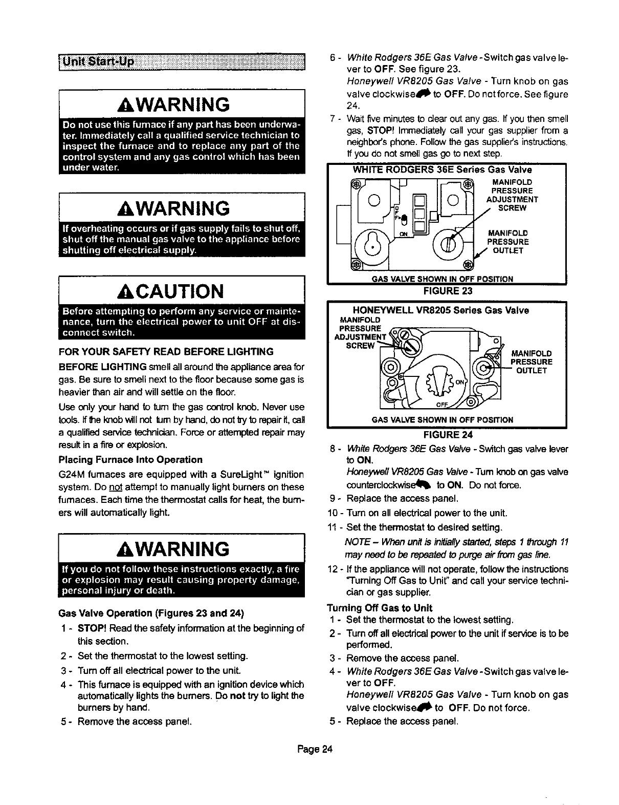
Gas Valve Operation (Figures 23 and 24)
1-STOP! Read the safetyinformation at the beginning of
this section.
2 - Set the thermostatto the lowest setting.
3-Turn off all electricalpower to the unit.
4 - This furnace is equippedwithan ignitiondevicewhich
automaticallylightsthe burners. D° not t_ to lightthe
burnersby hand.
5-Remove the access panel.
6-
7-
White Rodgers 36E Gas Valve -Switch gas valve le-
ver to OFF. See figure 23.
Honeywell VR8205 Gas Valve - Turn knob on gas
valve clockwise4_' to OFF. Do not force. See figure
24.
Wait five minutes to dear out any gas. If you then smell
gas, STOP! Immediately call your gas supplier from a
neighbor'sphone. Followthe gas supplier'sinstructions.
If you do not smell gas go to next step.
WHITE RODGERS 36E Series Gas Valve
MANIFOLD
PRESSURE
ADJUSTMENT
0o/SCREW
MANIFOLD
PRESSURE
/OUTLET
GAS VALVE SHOWN IN OFF POSITION
FIGURE 23
HONEYWELL VR8205 Series Gas Valve
MANIFOLD
PRESSURE -_
SCREW MAN,FOLD
PRESSURE
OUTLET
GAS VALVE SHOWN IN OFF POSITION
FIGURE 24
8 - WhiteRodgers 36E Gas Valve-Switchgas valvelever
to ON.
Honeywell VR8205 Gas Valve -Turn knobongasvalve
counterclonkwise_l_to ON. Do not force.
9-Replace the access panel.
10 - Turn onall electricalpower to the unit.
11- Set the thermostatto desired setting.
NOTE- When unitis inifia//ystaffed,steps1 _reugh 11
may need to be repeated to purge airfrom gas line.
12 - If the appliance will not operate, follow the instructions
"Turning Off Gas to Unit" and callyour servicetechni-
dan or gas supplier.
Turning Off Gas to Unit
1 - Set the thermostatto the lowest setting.
2 - Turnoffallelectricalpowerto the unitif serviceis tobe
performed.
3 - Remove the access panel.
4 - White Rodgers 36E Gas Valve -Switch gas valve le-
ver to OFF.
Honeywell VR8205 Gas Valve -Turn knob on gas
valve clockwise411_to OFF. Do notforce.
5 - Replace the access panel.
Page 24
HeatingSequenceOfOperation
1- Whenthermostatcallsforheat,combustionairblower
starts.
2 - Combustion air pressure switch proves blower opera-
tJon.Switch is factory set and requires no adjustment.
3 - After a 15 second prepurge, hot surface ignitor ener-
gizes.
4 - After a 20 second ignitor warm-up period, gas valve
solenoid opens.
5 - Gas is ignited, ignition sensor proves the flame and
combustion process continues.
6 - If flame is not detected after first ignition tdat, ignition
controlwillrepeat steps3and4fourmoretimesbefore
lockingoutthe gasvalve ("WATCHGUARD"flame fail-
ure mode). Ignitioncontrolwill then automatically re-
peat steps 3, 4, 5 and 6 after 60 minutes,
7- To interruptthe 60-minute °WATCHGUARD" pedod,
move thermostat_om "Heat" to "OFF" then back to
"Heat." Heatingsequencethen restartsat step f.
: • :. . • . . :::_ • : . ,: :::_:_:: _:::::: ;}::;:_::: :::::: ;_:1;'_:_:::::
Gas Flow
Tocheck for propergasflow to the combusf_onchamber,de-
terrninethe Bto(kW)klputfrom the unit ratingplate.Dividethis
inputraSngby the Btu (kW) per cubicfoot (cubicmeter)of
availablegas,The resultis the requirednumberof cubic feet
(cubicmeter)perhour.Determinethe flowof gas through the
gas meterfor two minutesend multiplyby 30 to get the houdy
flowof gas.
Gas Pressure
1 - Check the gas line pressure withthe unitfiringat maxi-
mum rate.A minimum of 4.5 in. w.c.for naturalgas or
11.0 in.w.c,forLP/prepanegas shouldbe maintained.
2- After the line pressure has been checked and ad-
justed, check the regulator pressure. Manifold pres-
suresare given in table 11. See figures23 and 24 for
manifoldpressureadjustmentscrewlocation.
Note -A natura! gas to LP/propane gas changeover kit is
requiredto convert the unit.
Refer totable 11 for manifoldpressure settingsfor installa-
tionsat differentaltitudesandfor differentfuels.
TABLE 11
MANIFOLDABSOLUTEPRESSURE(OUTLET}IN. W,C,(KPA)
Altitude - feet (m) above sia level
0-2000 2000-4500 4500-5500 5500-6500 6500-7500
FUEL (0-610) (610-1372) (1372-1676) (1676-1981) (1981÷2286)
3.5 3.5 (0,87)* 3.4 (0.85) 3,3 (0.82) 3.2 (0.80)
NAT (0.87)
6.6 6.5 (2.36)" 92 (2/29) 8,9 (221) 8.6 (2.14)
LP (2.36)
*No adjustment required.
NOTE -In Canada, certification for installations at eleva-
tions over 4500 feet (1372 m) is the jurisdiction of local au-
thorities.
The combustion air pressure switches are factory-set and
require no adjustment.
At elevations of 4500 feet (1372 m) or greater, replace the
factory-installed pressure switch with the switch listed in
table 12.
Unit Model
G24M-45
G24M-60
G24M-75
G24M-100
G24M-120
G24M-14_?
TABLE 12
Pressure Switch
Part Number
NO CHANGE
NO CHANGE
88J8001
18L2401
18L2401
NO CHANGE
Primary and Secondary Limits
The primarylimitis locatedon theheatingcompadmentves-
tibulepanel.Two secondarylimitsere locatedinthe blower
compartment,behind the blower.Theselimitsarefactory-set
andrequire no adjustment.
Flame Rollout Switches (Two)
These manuallyreset switchesare locatedjust abovethe
burnerbox. If tdpped,a check for adequatecombustion air
shouldbe made before resetting.
Combustion Air Pressure Switch
The combustion air pressureswitchis locatedonthe heat-
ing compartmentvestibule panel. This switchchecks for
proper combustion air blower operation before allowing
ignitiontrial,The switchis factory-setand requiresno ad-
justment.
Fan Control
The fan on time of 45 seconds is not adjustable. Fan off
time (time thatthe bloweroperates afterthe heat demand
has been satisfied) can be adjusted by flipping the dip
switcheslocated on the Surelightintegrated control.The
unitis shippedwitha factoryfan off settingof 90 seconds.
Fan off time will affect comfortand is adjustableto satisfy
individualapplications.See figure25.
Page 25
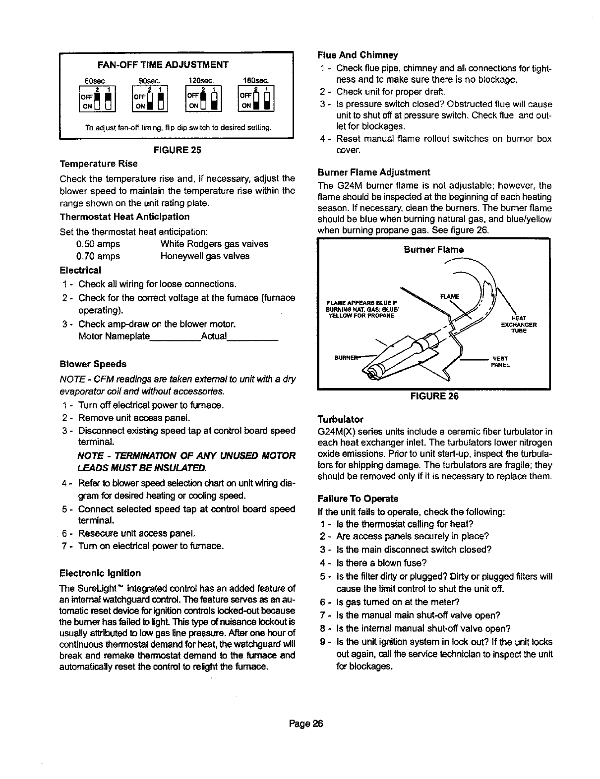
FAN-OFFTIMEADJUSTMENT
60sec. 90sec. 120sec. 180sec.
To adjust fan-off timing,flip dip switch to desired setting,
FIGURE 25
Temperature Rise
Check the temperature rise and, if necessary, adjust the
blower speed to maintainthe temperature rise withinthe
range shown on the unit ratingplate.
Thermostat Heat Anticipation
Set the thermostatheat anticipation:
0,50 amps White Rodgers gas valves
0.70 amps Honeywellgas valves
Electrical
1 - Check all wiring for loose connections.
2 - Check for the correctvoltage at the furnace (furnace
operating).
3-Check amp-draw on the blowermotor.
Motor Nameplate Actual
Blower Speeds
NOTE -CFM readingsare taken externalto unit with a dry
evaporator coiland withoutaccessories.
1 - Turn off electricalpower to furnace.
2-Remove unitaccess panel.
3 - Disconnectexistingspeedtap at control board speed
terminal.
NOTE -TERMINATION OF ANY UNUSED MOTOR
LEADS MUST BE INSULATED.
4 - Referto blower speedselectionchartonunitwidngdia-
gramfor desiredheatingor coolingspeed.
5 - Connect selected speed tap at control board speed
terminal.
6 - Resecure unitaccess panel.
7 - Turn on electricalpower to furnace.
Electronic Ignition
The SureLightTM integratedcontrolhas an addedfeatureof
an internalwatchguardcontrol.Thefeatureservesasan au-
tomaticresetdevicefor ignitioncontrolslocked-outbecause
the burnerhas failed to lighLThistype ofnuisancelockoutis
usuallyattributedto lowgas line pressure.Afterone hourof
continuousthermostatdemandforheat,the watchguardwill
break and remake thermostat demand to the furnace and
automaticallyreset the controlto relightthe furnace.
Flue And Chimney
1- Checkfluepipe,chimneyandall connections for tight-
ness and to make sure there is no blockage.
2 - Check unit forproper draft.
3 - Is pressureswitchclosed?Obstructed flue wi]]cause
unittoshutoffat pressure switch.Check flue and out-
letfor blockages.
4 - Reset manual flame rollout switches on burner box
cover.
Burner Flame Adjustment
The G24M burner flame is not adjustable; however, the
flame shouldbe inspectedat the beginning of each heating
season. If necessary,clean the burners.The burnerflame
shouldbe blue when burning naturalgas, and blue/yellow
when burningpropanegas. See figure 26.
Burner Flame
FLAME APPEARS BLUE IF
BURNING NAT. GAS; BLUE/
YELLOW FOR PROPANE,
-- VEST
PANEL
FIGURE 26
Turbulator
G24M(X) sedes unitsinclude a ceramic fiber turbulator in
each heat exchanger inlet. The turbulators lower nitrogen
oxide emissions.Prior to unit start-up, inspect the turbula*
tors for shipping damage. The turbulators are fragile; they
should be removed only if it is necessary to replace them.
Failure To Operate
If the unitfails to operate,check the following:
1 - Is the thermostatcallingfor heat?
2- Are access panelssecurely in place?
3 - Is the main disconnectswitchclosed?
4 - Is there a blownfuse?
5- Is the flltardirtyer plugged?Dirtyor ptuggedfilterswill
cause the limit controlto shutthe unitoff.
6 - Is gas turnedonat the meter?.
7-Is the manual mainshut-offvalve open?
8 - Is the internalmanual shut--offvalveopen?
9-Is the unitignitionsystem in lockout? If the unitlocks
outagain, call the servicetechnician to inspectthe unit
for blockages.
Page26
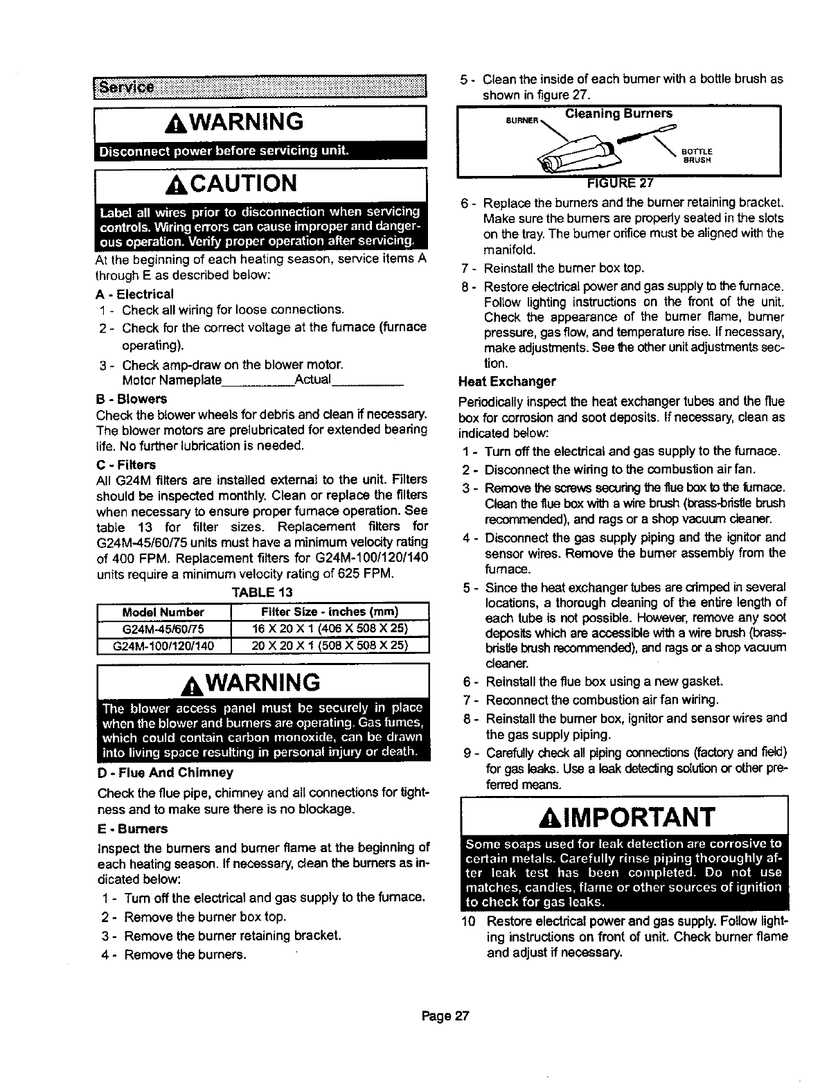
,CAUTION
At the beginning of each heating season, service items A
through E as described below:
A-Electrical
1 - Check all widng for loose connections.
2 - Check fur the correct voltage at the furnace (furnace
operating).
3 - Check amp-draw on the blower motor.
Motor Nameplate Actual
B-Blowers
Check the blower wheels for debris and cleanif necessary.
The blower motors are prelubdcated for extended bearing
life. No further lubrication is needed.
C-Filters
All G24M filters are installed external to the unit. Filters
should be inspectedmonthly. Clean or replace the filters
when necessary to ensure proper furnace operation.See
table 13 for filter sizes. Replacement filters for
G24M.-45/60/75 unitsmust have a minimumvelocityrating
of 400 FPM. Replacement filters for G24M-1OO/120/140
unitsrequirea minimum velocity ratingof 625 FPM.
TABLE t3
Model Number
G24M-45/60/75
G24M-100/120/140 IFilter Size -Inches (ram)
16 X 20 X 1 (406 X 508 X25)
20 X 20 X 1 (508 X508 X25)
AWARNING
D - Flue And Chimney
Check the flue pipe, chimneyand all connectionsfor tight-
ness and to make sure there is no blockage.
E-Burners
Inspect the burners and burner flame at the beginning of
each heatingseason.If necessary,clean the burnersas in-
dicated below:
1 - Turn off the electdcal and gas supplyto the furnace.
2- Remove the burner boxtop.
3 - Remove the burner retaining bracket,
4 - Remove the burners,
5 - Clean the insideof each bumer with a bottle brush as
shown infigure 27.
Cleaning Burners
BOTTLE
BRUSH
FIGURE 27 I
6- Replace the burners and the burner retaining bracket.
Make sure the burners are propedy seated in the slots
on the tray. The burner orifice must be aligned with the
manifold.
7-
8-
Reinstall the burnerbox top.
Restoreelectrical power andgas supply to the furnace.
Follow lighting instructions on the front of the unit.
Check the appearance of the burner flame, burner
pressure, gas flow, and temperature rise. If necessary,
make adjustments. See the other unit adjustments sec-
tion.
Heat Exchanger
Pedodicelly inspect the heat exchanger tubesand the flue
boxfor corrosionandsootdeposits.If necessary,cleanas
indicatedbelow:
1-Turn off the electricaland gas supplyto the furnace.
2 - Disconnectthe wiringto the combustionairfan.
3 - Remove the screws securingthe flue box to the furnace.
Clean the flue box with a wire brush (brass-bd_e brush
recommended),and rags or ashop vacuum cleaner.
4 - Disconnect the gas supplypiping and the ignitor and
sensor wires. Remove the burner assembly from the
furnace.
5- Sincethe heat exchangertubesare crimpedinseveral
locations, a thoroughdeaning of the entire lengthof
each tube is not possible. However,removeany soot
deposits whichare accessible witha wire brush (brass-
bristlebrushrecommended),andrags orashopvacuum
cleaner.
6 - Reinstallthe flue box using anew gasket.
7-Reconnectthe combustionair fan wiring.
8 - Reinstall the burner box, ignitor and sensor wires and
the gas supply piping.
9 - Carefully check all piping connections(factory andfield)
for gas leaks. Use a leak detec_ngsolutionor other pre-
ferrad means.
AIMPORTANT
10 Restore electricalpower and gas supply.Followlight-
ing instructionson front of unit. Check burner flame
and adjustif necessary.
Page 27
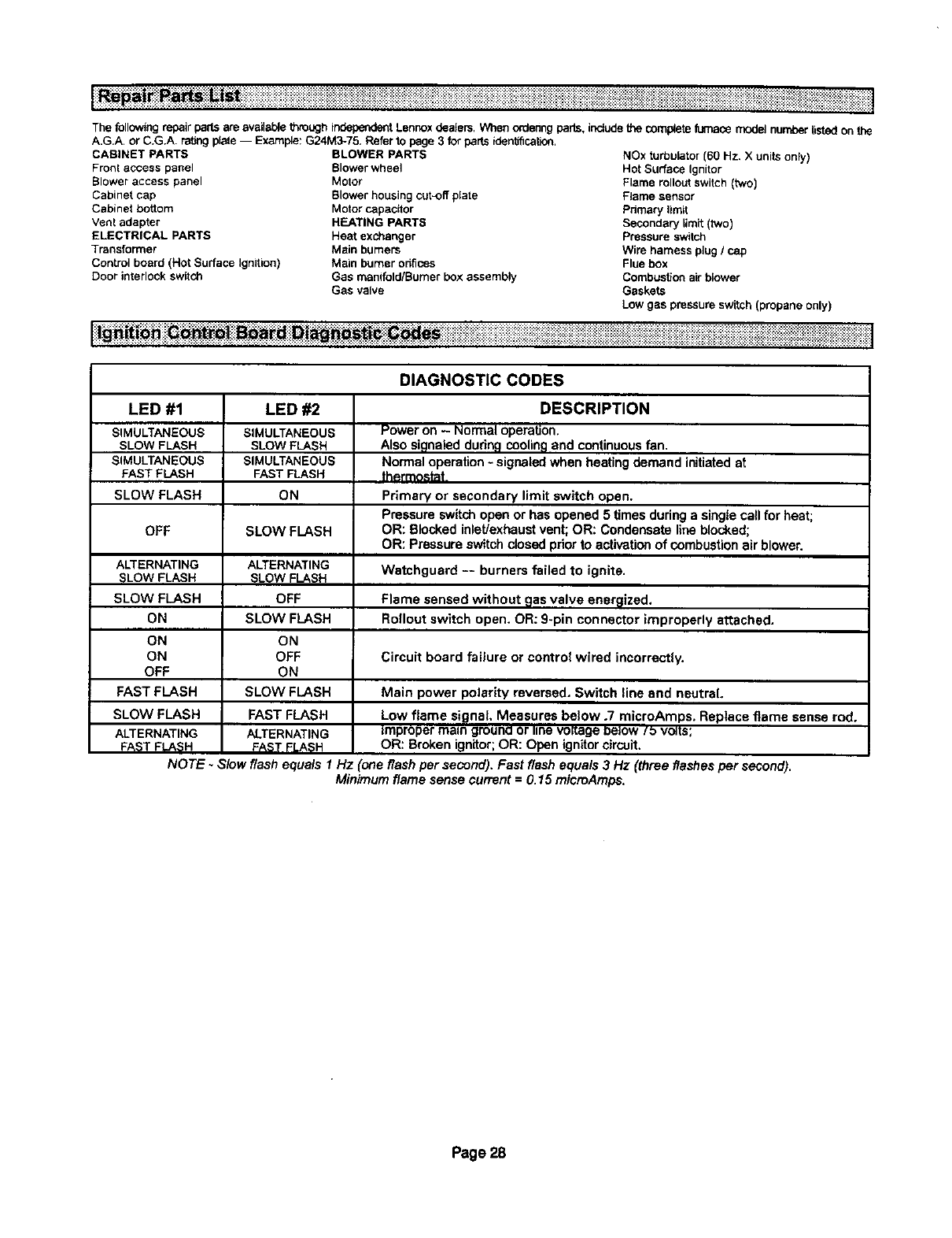
l_!_ _ _!_iiiiiiiiiiiiii!iiiiiiiiiiiiiii;i;;ilil;;il;illii iiiiiii iili i i i!ii;iiiiii;i;i;iii!i;i!!;!iii!il;iii;ii;iiiiiiiiiiiiiiiiiiiiiiiiiiii!iiiiiii_iiii!i_i_Ji_%_
The following repairpartsare availablethroughindependentLennoxdealers. When ordenngparts, includethe coreplet_furnace model numberlistedon the
A.G.A. or C.G.A. rating plate -- Example: G24M3-75. Refer to page 3 for parts iderdification.
CABINET PARTS
Front acoess panel
Blower access panel
Cabinet cap
Cabinet bottom
Vent adapter
ELECTRICAL PARTS
Transformer
Controlboard (Hot Sudace Ignition)
Door interlock switch
BLOWER PARTS
Blower wheel
Motor
Blower housing cut-off plate
Motor capacitor
HEATING PARTB
Heat exchanger
Main burners
Main burner orifices
Gas manifold/Burner box assembly
Gas valve
NOx turbulator [60 Hz, X units only)
Hot Surface Ignitor
Flame roliout switch (two)
FJame sensor
Primary limit
Secondary limit (two)
Pressure switch
Wire harness plug il cap
Flue box
Combustion air blower
Gaskets
Low gas pressure switch (propane only)
_ -,,_,-.----.-.--- _ .-._--_.-- ___..-_ --.-_,K_----_--_ .-- _--_._............ ........................................................ : : ::::::::::::::::::::::::::::::::::::::::::::::::::::::::::::: :::::::;::::
DIAGNOSTIC CODES
LED #1
SIMULTANEOUS
SLOW FLASH
SIMULTANEOUS
FAST FLASH
SLOW FLASH
OFF
ALTERNATING
SLOWFLASH
SLOW FLASH
ON
ON
ON
OFF
FAST FLASH
SLOW FLASH
ALTERNATING
FAST FLASH
LED #2
SIMULTANEOUS
SLOW FLASH
SIMULTANEOUS
FAST FLASH
ON
SLOW FLASH
ALTERNATING
SLOW FLASH
OFF
SLOW FLASH
ON
OFF
ON
SLOW FLASH
FAST FLASH
ALTERNATING
FAST FLASH
DESCRIPTION
Power on - Normal operation.
Also signaled dudn,qcoolingand continuousfan.
Normal operation-signaled when heating demand initiatedat
thermostat,
Primary or secondary limit switch open.
Pressure switchopen or has opened 5 times duringa single call for heat;
OR: Blocked inlet/exhaustvent; OR: Condensate line blocked;
OR: Pressure switch closed priorto activationof combustionair blower.
Watchguard -- burners failed to ignite.
Flame sensed without gas valve ensr_lized.
Rollout switch open. OR: 9-pin connector improperly attached.
Circuit board failure or control wired incorrectly.
Main power polariW reversed. Switch line and neutral.
Low flame signal Measures below .7 microAmps. Replace flame sense rod.
Improper main gmuna or line voKageeelow/_ volts;
OR: Broken ignitor;OR: Open ignitorcircuit.
NOTE -Slow flash equals 1 Hz (one flash per second), Fast flash equals 3Hz (three flashesper second).
Minimum flame sense current =0.15 microAmps.
Page 28
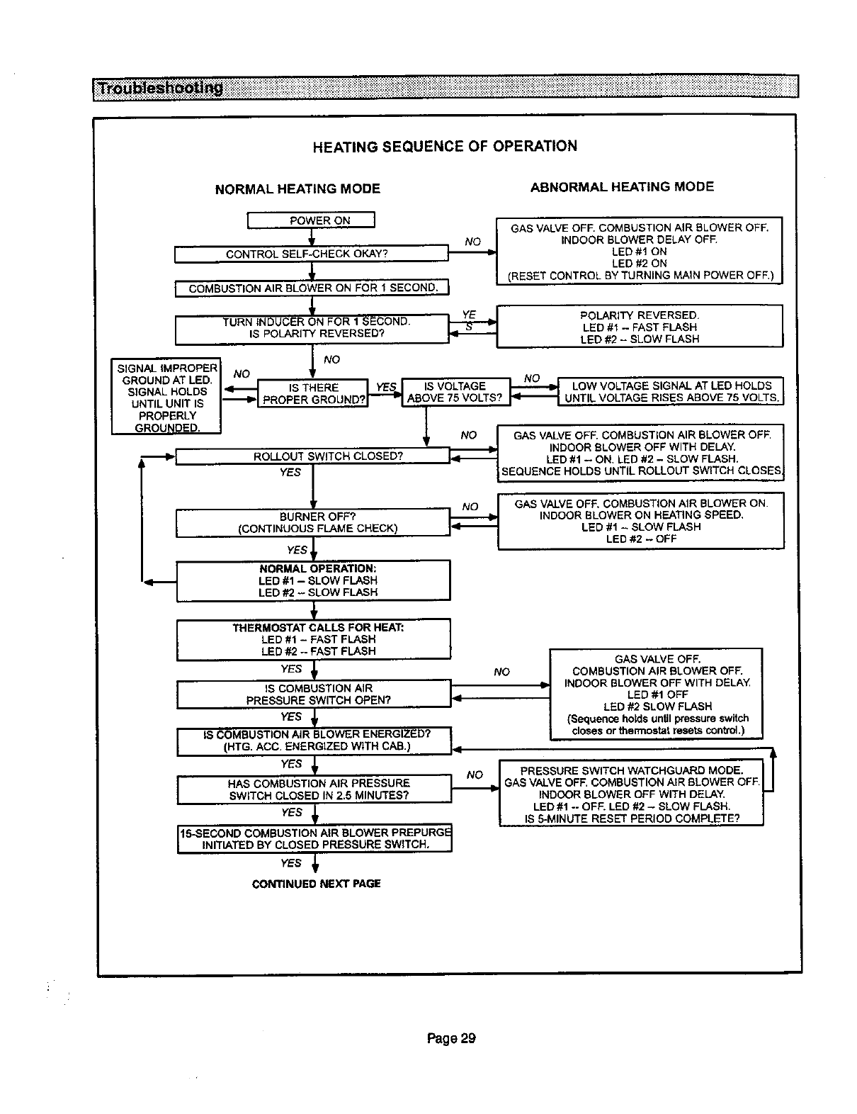
iiiiiiiiiiiiiiiiiiiiiiiiiilli!iliiiiiii!iiiii!i!i!ii!i!iiiiii iiiii iiiiiiiii!iii i!i iii i i i i i i;i ili!iiiii!iiiiiiiiiiiii!_ii_iiiii!_!_!_iiiiiiiiiii_iiiiii_i_i_i_i_iii_i_i_iiiiiii_i_i_iiiii!i!i_i_i_iii!iii_i_i____iiiiiiiiiii_ii__iiii
HEATING SEQUENCE OF OPERATION
NORMAL HEATING MODE ABNORMAL HEATING MODE
POWER ON ]
No
I CONTROL SELF-CHECK OKAY?
I COMBUSTION AIR SLOWER ON FOR I SECOND. I
TURN INDUCER ON FOR 1 SECOND. I_
I IS POLARITY REVERSED?
GAS VALVE OFF. COMBUSTION AIR BLOWER OFF.
INDOOR BLOWER DELAY OFF.
LED#1 ON
LED #2 ON
(RESET CONTROL BY TURNING MAIN POWER OFF,)
POLARITY REVERSED.
LED #1 -FAST FLASH
LED #2 -SLOW FLASH
ISIGNAL IMPROPERI / NO
GROUND AT LED NO •NO
SIGNAL HOLDS _1 IS THERE I YES I S VOLTAGE _ LOW VOLTAGE SIGNAL AT LED HOLDS
UNTIL UNIT IS "_1 PROPER GROUND?r_I ABOVE 75vOLTS? _ UNTIL VOLTAGE RISES ABOVE75 VOLTS'I
PROPERLY
GROUNDED. NO I GAS VALVE OFF. COMBUSTION AIR BLOWER OFF, I
ROLLOUT SWITCH CLOSED_ il INDOOR BLOWER OFF WITH DELAY. I
"_ll" I•t'il'_ I LED #1 - ON. LED #2 - SLOW FLASH. I
YES I | SEQUENCE HOLDS UNTIL ROLLOUT SWITCH CLOSESt
GAS VALVE OFF. COMBUSTION AIR BLOWER ON,
NO
I
INDOOR BLOWER ON HEATING SPEED. I
LED #1 - SLOW FLASH I
LED #2 - OFF
GAS VALVE OFF.
COMBUSTION AIR BLOWER OFF.
INDOOR BLOWER OFF WITH DELAY
LED #1 OFF
I LED #2 SLOW FLASH
(Sequence ho_dsuntil pressure switch
closes or thermostat resets contmt.)
PRESSURE SWITCH WATCHGUARD MODE. IT
GAS VALVE OFF. COMBUSTION AIR BLOWER OFF.I I
INDOOR BLOWER OFF WITH DELAY. r-
LED #1 -- OFF. LED #2 - SLOW FLASH. |
IS S-MINUTE RESET PERIOD COMPLETE? l
[BURNER OFF?
(CONTINUOUS FLAME CHECK)
YES
NORMAL OPERATION: I
LED #1 - SLOW FLASH
LED #2 - SLOW FLASH
+
THERMOSTAT CALLS FOR HEAT:
LED #1 - FAST FLASH
LED #2 - FAST FLASH
YES i
I IS COMBUSTION AIR I
PRESSURE SWITCH OPEN? I-
YES
IIS COMBUSTION AIR BLOWER ENERGIZED? I
(HTG. ACC. ENERGIZED WITH CAB.) =,I
YES _
I HAS COMBUSTION AIR PRESSURE
SWITCH CLOSED IN 2.5 MINUTES?
YES
15-SECOND COMBUSTION AIR BLOWER PREPURGEI
INITIATED BY CLOSED PRESSURE SW TCH. /
YES _
CONTINUED NEXT PAGE
Page 29
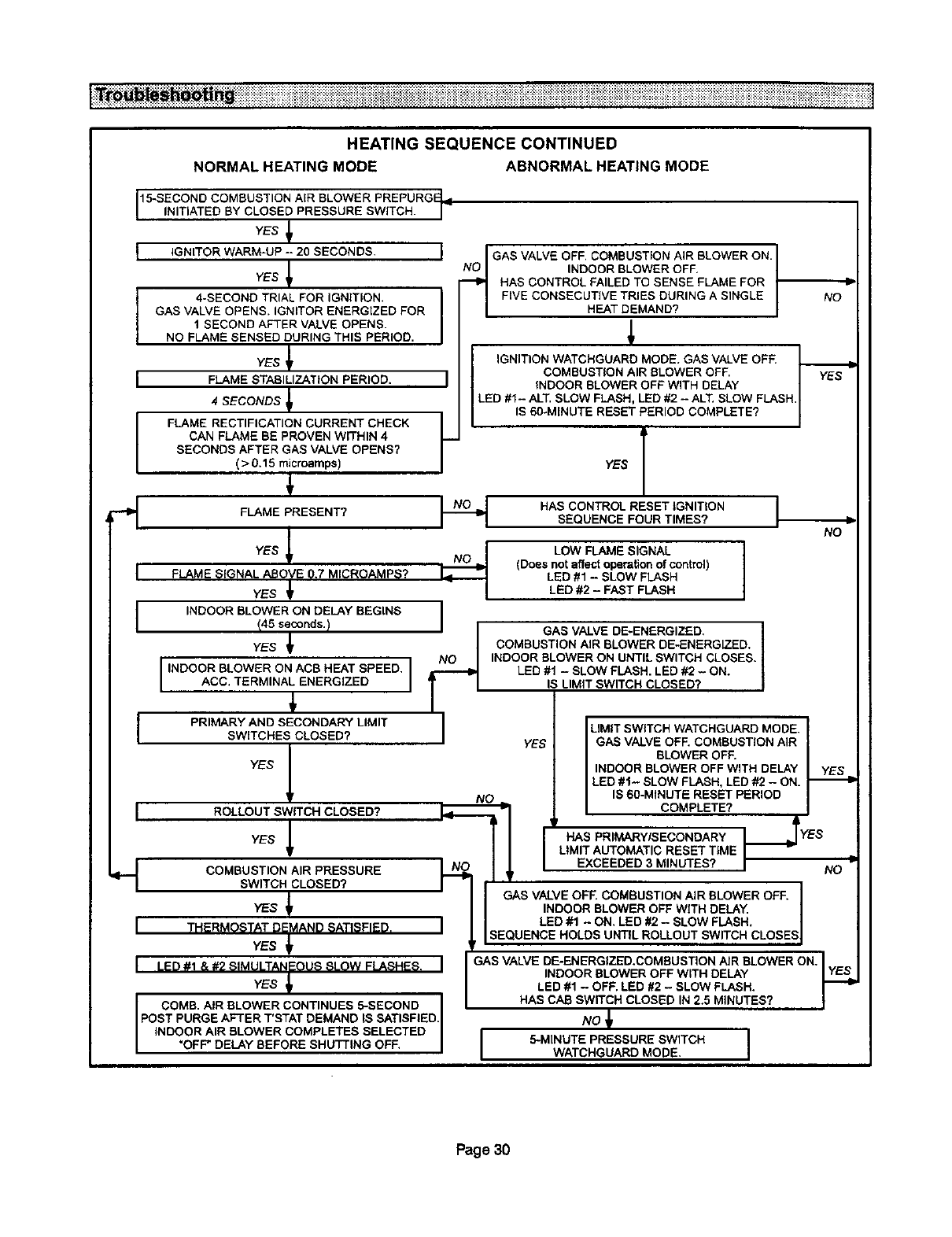
HEATINGSEQUENCECONTINUED
NORMALHEATINGMODE ABNORMALHEATINGMODE
15-SECOND COMBUSTION AIR BLOWER PREPURGF I11
N T ATED BY CLOSED PRESSURE SW TCH. /
YES
[ IGNITOR WARM-UP -- 20 SECONDS. I
YES _
4-SECOND TRIAL FOR IGNITION.
GAS VALVE OPENS. IGNITOR ENERGIZED FOR
I SECOND AFTER VALVE OPENS.
NO FLAME SENSED DURING THIS PERIOD.
YES
I FLAME STABILIZATION PERIOD. I
4 SECONDS _
FLAME RECTIFICATION CURRENT CHECK /
CAN FLAME BE PROVEN WITHIN 4 P
SECONDS AFTER GAS VALVE OPENS?
( > 0.15 microamps)
FLAME PRESENT? I--_
YES _ NO_[
FLAME SIGNAL ABOVE 0.7 MICROAMPS?
YES _
I
IINDOOR BLOWER ON DELAY BEGINS /
/45 seconds.)
YES _
[INDOOR BLOWER ON ACB HEAT SPEED. 1ACC. TERMINAL ENERGIZED
PRIMARY AND SECONDARY LIMIT I
SWITCHES CLOSED? I
YES 1
._GAS VALVE OFF. COMBUSTION AIR BLOWER ON. _O
INDOOR BLOWER OFF.
HAS CONTROL FAILED TO SENSE FLAME FOR
FIVE CONSECUTIVE TRIES DURING A SINGLE
HEAT DEMAND?
/
IGNITION WATCHGUARD MODE. GAS VALVE OFF. I .
COMBUSTION AIR BLOWER OFF, I y_S_YES
INDOOR BLOWER OFF WITH DELAY
LED #1 - ALT, SLOW FLASH, LED #2 - ALT. SLOW FLASH,
S60-M NUTE RESET PER OD COMPLETE? /
/
YES T
HAS CONTROL RESET IGNITION I
SEQUENCE FOUR TIMES?
LOW FLAME SIGNAL |
(Does not affect operation of control) J
LED #1 - SLOW FLASH
LED #2 - FAST FLASH
GAS VALVE DE-ENERGIZED.
COMBUSTION AIR BLOWER DE-ENERGIZED.
INDOOR BLOWER ON UNTIL SWITCH CLOSES.
LED #1 - SLOW FLASH. LED #2 - ON.
IS LIMIT SWITCH CLOSED?
LIMIT SWITCH WATCHGUARD MODE.
GAS VALVE OFE COMBUSTION AIR
BLOWER OFF.
INDOOR SLOWER OFF WITH DELAY
LED #1- SLOW FLASH, LED #2 - ON.
YES
NO L IS 60-MINUTE RESET PERIOD
IROLLOUTyEsSWITCH_CLOSED? _ [ COMPLETE?
/ HAS PRIMARY/SECONDARY I ,
LIMIT AUTOMATIC RESET TIME I
I-.--I COMBUSTION AIR PRESSURE EXCEEDED 3 MINUTES? I
l SWITCH CLOSED?
/ GAS VALVE OFF. COMBUSTION AIR BLOWER OFF.
YES fINDOOR BLOWER OFF WITH DELAY.
ILED #1 - ON. LED #2 - SLOW FLASH.
I THERMOSTAT DEMAND SATISFIED. I LSEQUENCE HOLDS UNTIL ROLLOUT SWITCH CLOSES
YES
I {,_) #1 & #2 SIMULTANEOUS SLOW FLASHES. I
YES
COMB. AIR BLOWER CONTINUES 5-SECOND
POST PURGE AFTER T'STAT DEMAND IS SATISFIED.
INDOOR AIR BLOWER COMPLETES SELECTED
OFF" DELAY BEFORE SHUTT NG OFF.
;70
-S
NO
GAS VALVE DE-ENERGIZED.COMBUSTION AIR BLOWER ON. ]
INDOOR BLOWER OFF WITH DELAY IYES=
LED #1 - OFF. LED #2 - SLOW FLASH.
HAS CAB SWITCH CLOSED IN 2.5 MINUTES? |
NO
I5-MINUTE PRESSURE SWITCH I
WATCHGUARD MODE.
Page 30
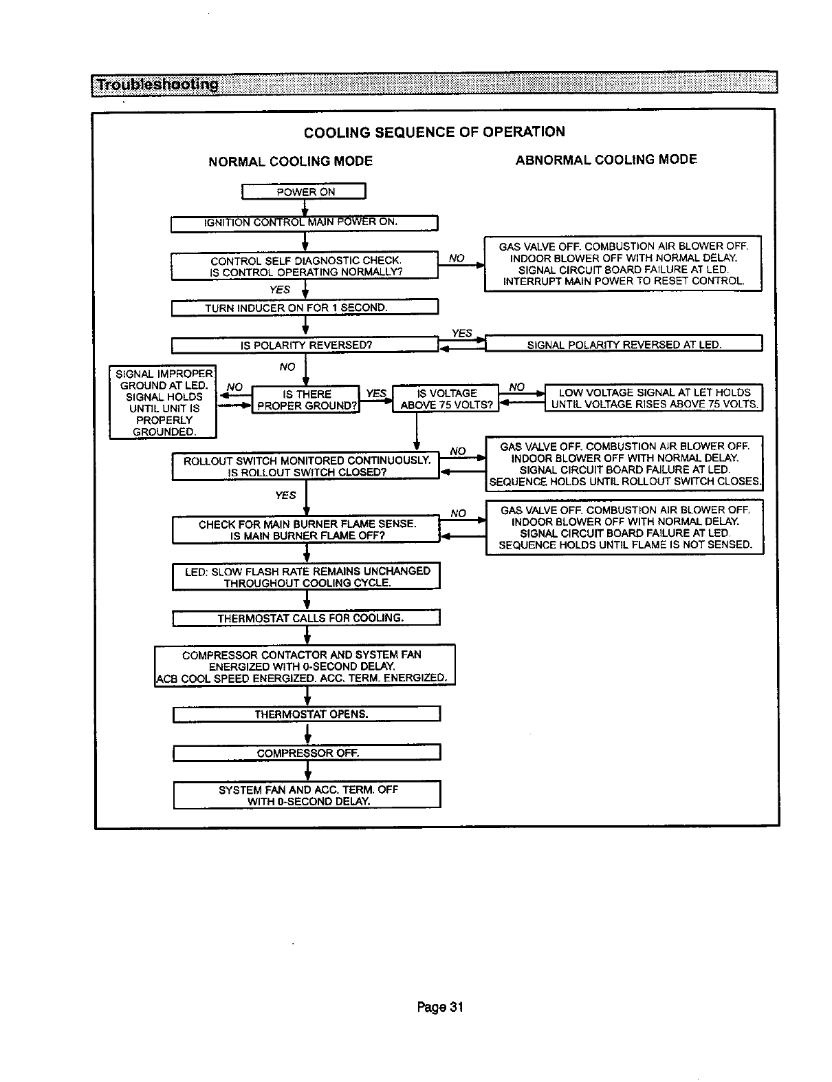
COOLINGSEQUENCEOFOPERATION
NORMAL COOLING MODE ABNORMAL COOLING MODE
IPOWER ON I
IIGNITION CONTROL_MAIN POWER ON. I
I CONTROL SELF DIAGNOSTIC CHECK.IS CONTROL OPERATING NORMALLY?
YES _
I TURN INDUCER ON FOR 1 SECOND. I
i
YES _,
I IS POLARITY REVERSED? i= -
SIGNAL IMPROPER
GROUND AT LED.
SIGNAL HOLDS
UNTIL UNIT IS
GAS VALVE OFF. COMBUSTION AIR BLOWER OFF. I
INDOOR BLOWER OFF WITH NORMAL DELAY. I
SIGNAL CIRCUIT BOARD FAILURE AT LED.
INTERRUPT MAIN POWER TO RESET CONTROL,
SIGNAL POLARITY REVERSED AT LED.
IS THERE IYES..I IS VOLTAGE _ LOW VOLTAGE SIGNAL AT LET HOLDS
"'"_1 PROPER GROUND?I_" _ABOVE 75 VOLTS? !_1--_1 UNT LVOLTAGE R SES ABOVE 75 VOLTS.
PROPERLY I
GROUN.DEEL
IUoU;'
YES NO
I CHECK FOR MAIN BURNER FLAME SENSE.
IS MAIN BURNER FLAME OFF? I_1_-
I LED:SLOWFLABH TEREMAINSUNC NOEDITHROUGHOUT COOLING CYCLE.
I THERMOSTAT CALLS FOR COOLING. I
COMPRESSOR CONTACTOR AND SYSTEM FAN
ENERGIZED WITH 0-SECOND DELAY.
ACB COOL SPEED ENERGIZED. ACC. TERM. ENERG ZED.
GAS VALVE OFF. COMBUSTION AIR BLOWER OFF.
INDOOR BLOWER OFF WITH NORMAL DELAY,
SIGNAL CIRCUIT BOARD FAILURE AT LED,
SEQUENCE HOLDS UNTIL ROLLOUT SWITCH CLOSES.
GAS VALVE OFF, COMBUSTION AIR BLOWER OFF.
INDOOR BLOWER OFF WITH NORMAL DELAY.
SIGNAL CIRCUIT BOARD FAILURE AT LED,
SEQUENCE HOLDS UNTIL FLAME IS NOT SENSED.
THERMOSTATOPENS. I
COMPRESSOR OF_ I
SYSTEM FAN AND ACC. TERM. OFF I
WITH 0-SECOND DELAY. I
Page 31
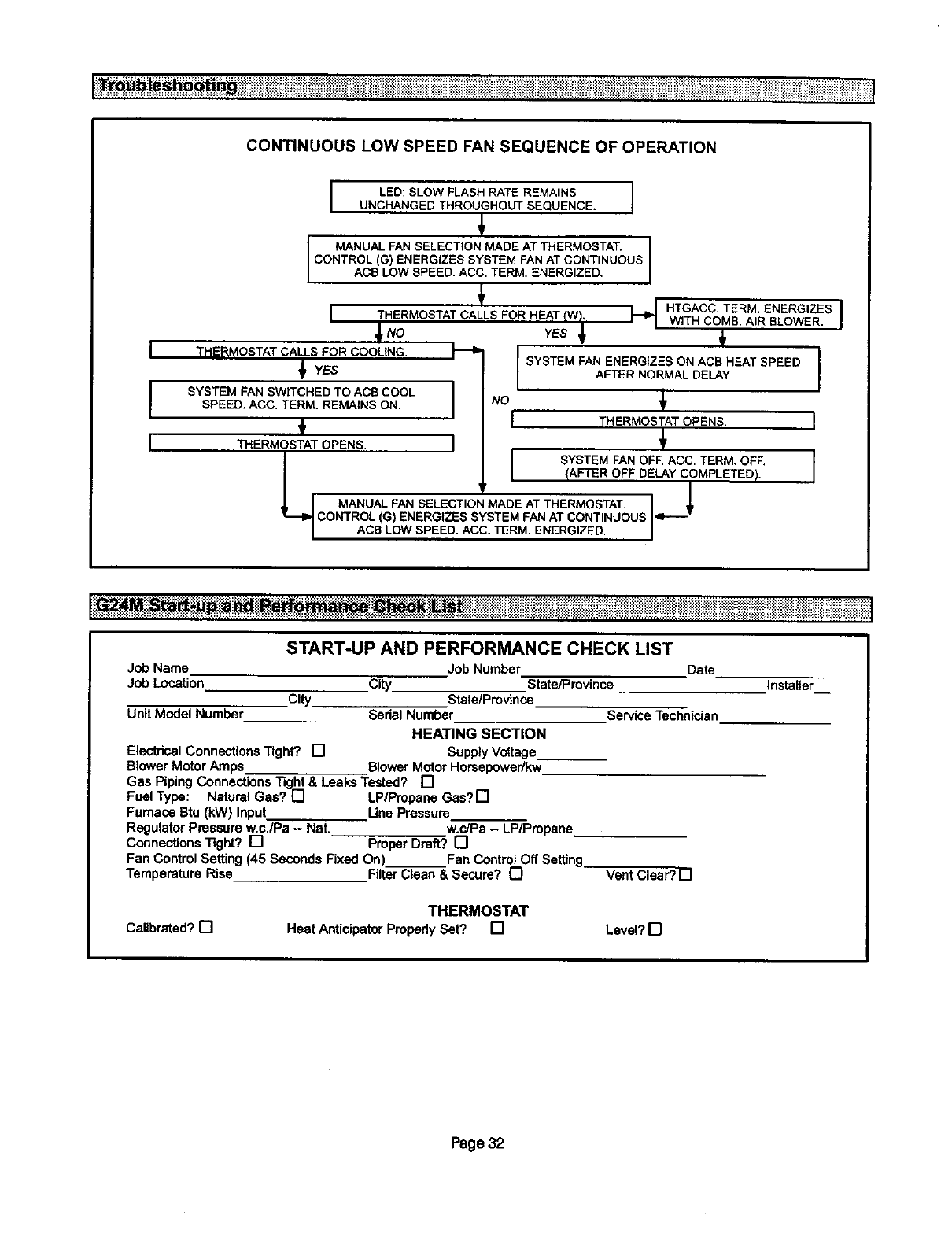
• . . .................................................................................. •.......... ,.................................................... •..................... .......
...................... ..... ...................................................................................... :+_:+.:_:+:_.,..:.:.:+:,:,_._._:._::_:_.................... ::::::::_:+_::_:::::_::_:::::_i%_::
CONTINUOUS LOW SPEED FAN SEQUENCE OF OPERATION
I
I
I
_NO
THERMOSTAT CALLS FOR COOLING.
_1 YES
SYSTEM FAN SWITCHED TO ACB COOL
SPEED. ACC. TERM, REMAINS ON.
ILED:SLOWFLASHRATEREMAINS I
UNCHANGEDTHROUGHOUTSEQUENCE. I
MANUALFANSELECTIONMADEAT THERMOSTAT.
CONTROL (G) ENERGIZESSYSTEMFANAT CONTINUOUS
ACBLOWSPEED.ACC,TERM.ENERGIZED.
ITHERMOSTAT CALLS FOR HEAT (W),
I
HTGACC.TERM.ENERGIZES1
WITH COMB.AIR BLOWER. I
YESI
SYSTEM FAN ENERGIZES ON ACB HEAT SPEED
AFTER NORMAL DELAY
THERMOSTATOPENS.
THERMOSTAT OPENS.
_._ I SYSTEM FAN OFF, ACC. TERM. OFF.
I /AFTER OFF DELAY COMPLETED)./
MANUAL FAN SELECTION MADE AT THERMOSTAT. !It
CONTROL (G) ENERGIZES SYSTEM PAN AT CONTINUOUS I'i'-"-"
ACB LOW SPEED. ACC. TERM. ENERGIZED. I
Job Name
Job Location
City
Unit Model Number
Electrical Connections Tight? []
Blower MotorAJ'nps Blower Motor Horsepowedkw
Gas Piping Connections]3ght & Leaks Tested? []
Fuel Type: Natural Gas? [] LP/Propane Gas? []
Furnace Btu (kW) Input Une Pressure
Regulator Pressure w.c.IPa - Nat. w.c/Pa - LP/Pmpane
ConnectionsTight? [] ProperDraft? []
Fan Control Setting (45 Seconds Fixed On) Fan Control Off Setting
Temperature Rise FilterClean & Secure? []
START-UP AND PERFORMANCE CHECK LIST
Job Number Date
City State/province
State/province
Serial Number Service Technician
HEATING SECTION
Supply Voltage_
Vent Clear? []
Installer__
THERMOSTAT
Calibrated?[] HeatAnticipatorPropedySet? [] Level?D
Page 32
