LENNOX Furnace/Heater, Gas Manual L0406249
User Manual: LENNOX LENNOX Furnace/Heater, Gas Manual LENNOX Furnace/Heater, Gas Owner's Manual, LENNOX Furnace/Heater, Gas installation guides
Open the PDF directly: View PDF ![]() .
.
Page Count: 31
LENNDX
©2000 Lennox Industries Inc.
Dallas, Texas, USA
INSTALLATION
INSTRUCTIONS
G26 SERIES UNITS
Technical
GAS UNITS _Publications
504,228M
11/2000 Litho U.S.A.
Supersedes 503,885M
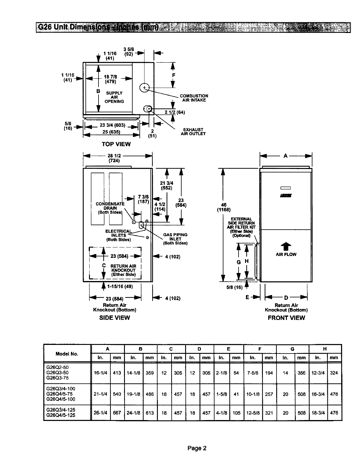
Unit Dimensions ............................... 2
G26 Parts Identification ......................... 3
Requirements .................................. 4
General ....................................... 4
Installation - Setting Equipment .................. 5
Return Air Opening Guidelines ................... 5
Filters & Optional Filter Assembly ................ 6
Duct System ................................... 7
Pipe & Fittings Specifications .................... 7
Vent Piping Guidelines .......................... 8
Joint Cementing Procedure ...................... 8
Venting Practices ............................... 9
Gas Piping ................................... 15
Electrical ..................................... 16
Unit Start-Up ................................. 20
Gas Pressure Adjustment ...................... 21
High Altitude Information ....................... 22
Other Unit Adjustments ........................ 22
Service ...................................... 23
Repair Parts .................................. 26
Troubleshooting ............................... 26
Start-Up & Performance Check List .............. 31
RETAIN THESE INSTRUCTIONS
FOR FUTURE REFERENCE
Do not store or use gasoline or other
flammable vapors and liquids in the vi-
cinity of this or any other appliance.
Installation and service must be per-
formed by a qualified installer, service
agency or the gas supplier.
WHAT TO DO IF YOU SMELL GAS:
• Do not W to light any appliance.
• Extinguish any open flames.
•Do not touch any electrical switch; do not use
any phone in your building.
• Immediately call your gas supplier from a
neighbor's phone. Follow the gas supplier's
instructions.
•If you cannot reach your gas supplier, call the
fire department.
11/00 504,228M
I|UUWIIMLIII Page1 IIIHIIlUlIIIIIgIIHIIIIIlaHII
1 1116
(41)
5/8
116)-I P
35/8 - I,
.L 1 1/16 (92) _ _I-
T (41) l /
_'_ 2_-_ EXHAUST
25 (635) _(51) AIR OUTLET
TOP VIEW
(724)
DRNN
ELECTRICAL
INLET
(Both Sides)
_--23 (584) --_
IcRETURNAIR_
L_ KNOCKOUT
(Either Side)
,1-15/18(,,)I
23 (584)
Return Air
Knockout (Bottom)
SIDE VIEW
'T
21 3/4
(552)
23
(684)
GAS PIPING
INLET
(Both sides)
4 (102)
L 4(102)
T
46
(1168)
EXTERNAL
SIDERE'RJRN
AIR RL'I-r.RKIT
(Bth_S_e)
(opeo._ ,
G H
5/8(
E-I'
qlm A-_---I_
I I
/mmr
t
AiR FLOW
Return Air
Knockout (Bottom)
FRONT VIEW
Model No, A B C D E F G H
In, mm in. mm In. mm in. mm In. mm In. mm in. mm In. mm
G26Q2-5O
G26Q3-50 16-1/4 413 14-1/8 359 12 305 12 305 2-1/8 54 7-5/8 194 14 356 12-314 324
G26Q3-75
G26Q3/4-100
G26Q4/5-75 21-1/4 540 19-1/8 486 18 457 18 ; 457 1-5/8 41 10-1/8 257 20 508 18-3/4 476
G26Q4/5-100
G26Q3/4-125
G26Q4/5-125 26-114 667 24-1/8 613 18 457 18 457 4-1/8 105 12-5/8 321 20 508 18-3/4 476
Page 2
G26 Pa_ A_ gement ....
n, _,
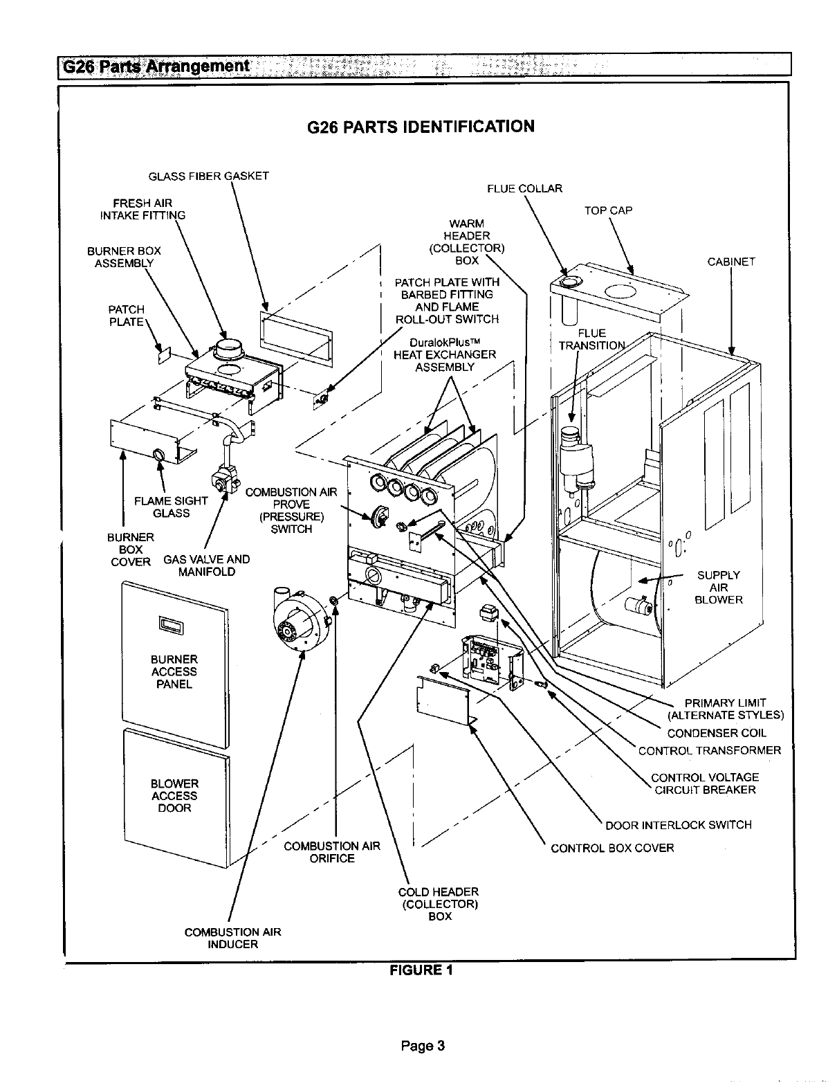
G26 PARTS IDENTIFICATION
GLASS FIBER GASKET
FRESH AIR
INTAKE FITTING
BURNER BOX _l
ASSEMBLY _."
J
PATCH
GLASS
BURNER
BOX
COVER GAS VALVE AND
MANIFOLD
BURNER
ACCESS
PANEL
BLOWER
ACCESS
DOOR
PROVE
(PRESSURE)
SWITCH
/
J
COMBUSTION AIR
ORIFICE
FLUE COLLAR
WARM
HEADER
(COLLECTOR)
BOX
PATCH PLATE WITH
i BARBED FITTING
AND FLAME
ROLL-OUT SWITCH
DuralokPlus TM
HEAT EXCHANGER
ASSEMBLY ,_
FLUE
TRANSITIO
CABINET
SUPPLY
AIR
BLOWER
PRIMARY LIMIT
(ALTERNATE STYLES)
COIL
TRANSFORMER
CONTROL VOLTAGE
CIRCUIT BREAKER
DOOR INTERLOCK SWITCH
CONTROL BOX COVER
COMBUSTION AIR
INDUCER
COLD HEADER
(COLLECTOR)
BOX
FIGURE 1
Page 3
All G26 units are CSA International certified to ANSI
Z21.47 and CSA 2.3 standards.
In the USA, installation of Lennox gas central fumaces must
conform with local building codes. In the absence of local
codes, units must be installed according to the current Na-
tional Fuel Gas Code (ANSI-Z223.1) in the United States.
The National Fuel Gas Code is available from the following
address:
American National Standards Institute, Inc.
11 West 42nd Street
New York, NY 10036
In Canada, installation must conform with current National
Standard of Canada CAN/CGA-B149.1 "Installation Code
for Natural Gas Burning Appliances and Equipment" and
CAN/CGA-B149.2 "Installation Code for Propane Gas
Burning Appliances and Equipment," local plumbing or
waste water codes and other applicable local codes.
Adequate clearance must be made around the air open-
ings into the vestibule area. Provisions must be made for
proper operation and for combustion air and ventilation air
supply according to the current National Fuel Gas Code or
CAN/CGA-B149 standards.
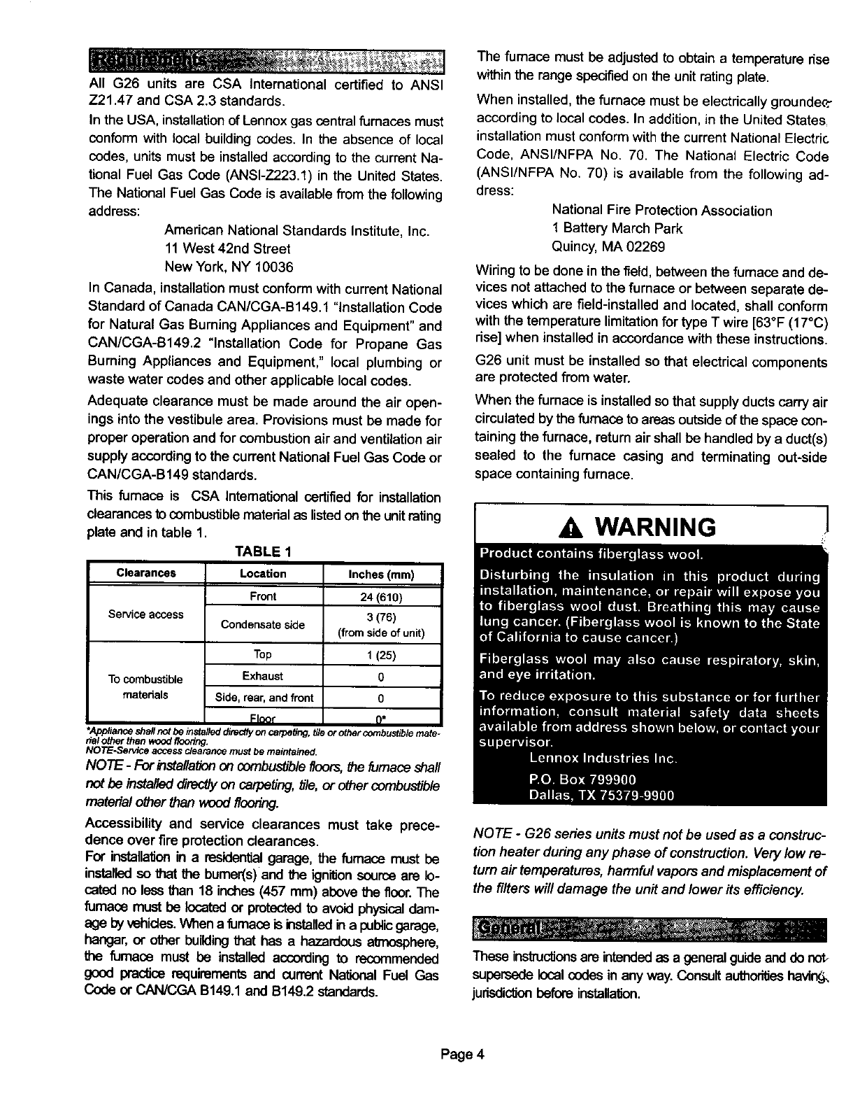
This fumaca is CSA Intemational certified for installation
clearances to combustible matedal as listed on the unit rating
plate and in table 1.
TABLE 1
Clearances
Service access
To combustible
materials
Location
Front
Condensate side
Top
Exhaust
Side, rear, and front
Flnor
Inches (ram)
24 (610)
3 (76)
(fromsideof unit)
1 (25)
0
0
o*
*Appliance shall not be installed directly on carpeting, tile or other combustible mate-
rial other than wood flooring.
NOTE-Service access clearance mum be rnaintalee_
NOTE -For installation on combustible floors, the fumace shall
not be installed directlyon carpeting, bTe,or o_er combustible
material other than wood flooring.
Accessibility and service clearances must take prece-
dence over fire protection clearances.
For installation in a residential garage, the fumace must be
installed so that the bumer(s) and the ignitionsource are lo-
cated no less than 18 inches (457 mm) above the floor. The
furnace must be located or protected to avoid physical dam-
age by vehicles.When a fumace is installedin a publicgarage,
hangar, or other buildingthat has a hazardous atmosphere,
the fumaca must be installed according to recommended
good practice requirements and current Na'donalFuel Gas
Code or CAN/CC_ B149.1 and B149.2 standards.
The fumace must be adjusted to obtain atemperature dse
withinthe range specified on the unit rating plate.
When installed, the furnace must be electrically grounde_:
according to local codes. In addition, in the United States
installation must conform with the current National Electric
Code, ANSI/NFPA No. 70. The National Electric Code
(ANSI/NFPA No. 70) is available from the following ad-
dress:
National Fire Protection Association
1 Battery March Park
Quincy, MA 02269
Wiring to be done in the field, between the furnace and de-
vices not attached to the furnace or between separate de-
vices which are field-installed and located, shall conform
with the temperature limitation for type T wire [63°F (17°C)
rise] when installed in accordance with these instructions.
G26 unit must be installed so that electrical components
are protected from water.
When the furnace is installed so that supplyducts carry air
circulated by the furnace to areas outside of the space con-
taining the furnace, return air shall be handled by a duct(s)
sealed to the fumaca casing and terminating out-side
space containing furnace.
41 WARNING /
NOTE - G26 series units must not be used as aconstruc-
tion heater during any phase of construction. Very low re-
turn air temperatures, harmful vapors and misplacement of
the filters will damage the unit and lower its efficiency.
These inslructJonsare intendedas a general guideand do not_
supersede local codes in any way. Consult authoritieshavir_
judsdic_onbefore installation.
Page 4
Shipping and Packing List
1 - Assembled G26 furnace
1-Bag assembly containing
1 - Electrical make-up box
1 - Wiring harness
1 - Snap bushing
2 - Filter clips
1 - 3 inch x 2 inch vent transitionpiece (-100, -125 units
only)
1 - Adapter
1 - Condensate plug
1 - Nipple
1 - Brown accessory wire
1 - Green ground wire
3 - Wire nuts
2 - Star washers
Shipping Damage
Check equipment for shipping damage. If you find any
damage, immediately contact the last carrier,
WARNING 1
WARNING
Select a location that allows for required clearances
listed on the unit rating plate. Also consider gas supply
connections, electrical supply, vent connection and
installation and service clearances [24 inches (610 mm)
at unit front]. The furnace must be level.
NOTE -1/3 and 1/2 hp blower motors are equipped with ei-
ther four flexible mounting legs or three flexible legs and
one rigid leg. The rigid leg is equipped with a shipping bolt
and a flat white plastic washer (rather than the rubber
mounting grommet used w#h a flexible mounting leg). This
shipping bolt and flat washer must be removed before the
furnace is put into operation. Once the shipping bolt and
washer are removed, the rigidleg will not touch the blower
housing.
CAUTION
Return air can be brought in either side or at the bottom of
the unit. Scribe lines show the outline of each side and the
bottom return air opening.
Bottom Return Air Applications
If cold air return is to terminate through the floor under the
furnace, a direct, airtight and sealed connection must be
made to the bottom of the furnace.
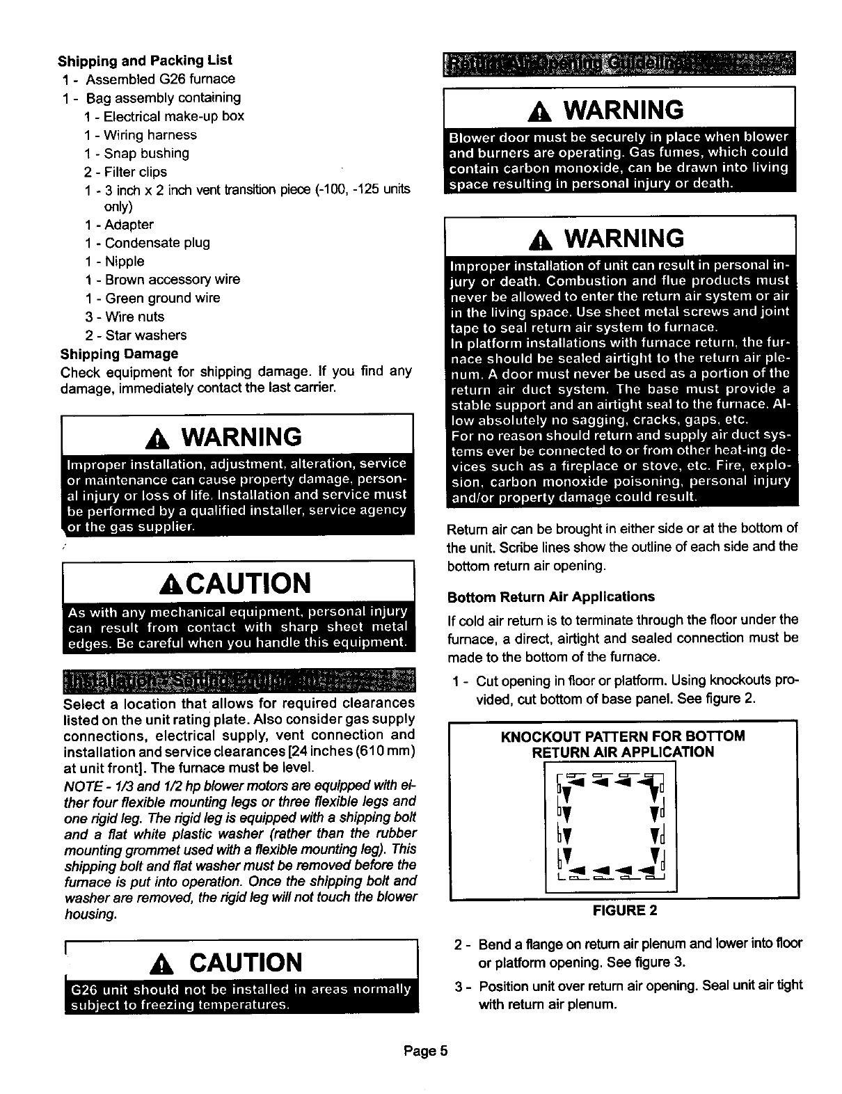
1 - Cut opening infloor or platform. Using knockouts pro-
vided, cut bottom of base panel. See figure 2.
KNOCKOUT PATTERN FOR BOTTOM
RETURN AIR APPLICATION
tv
FIGURE 2
2 - Bend a flange on returnair plenum and lower into floor
or platform opening. See figure 3.
3-Position unit over return air opening. Seal unit air tight
with return air plenum.
Page 5
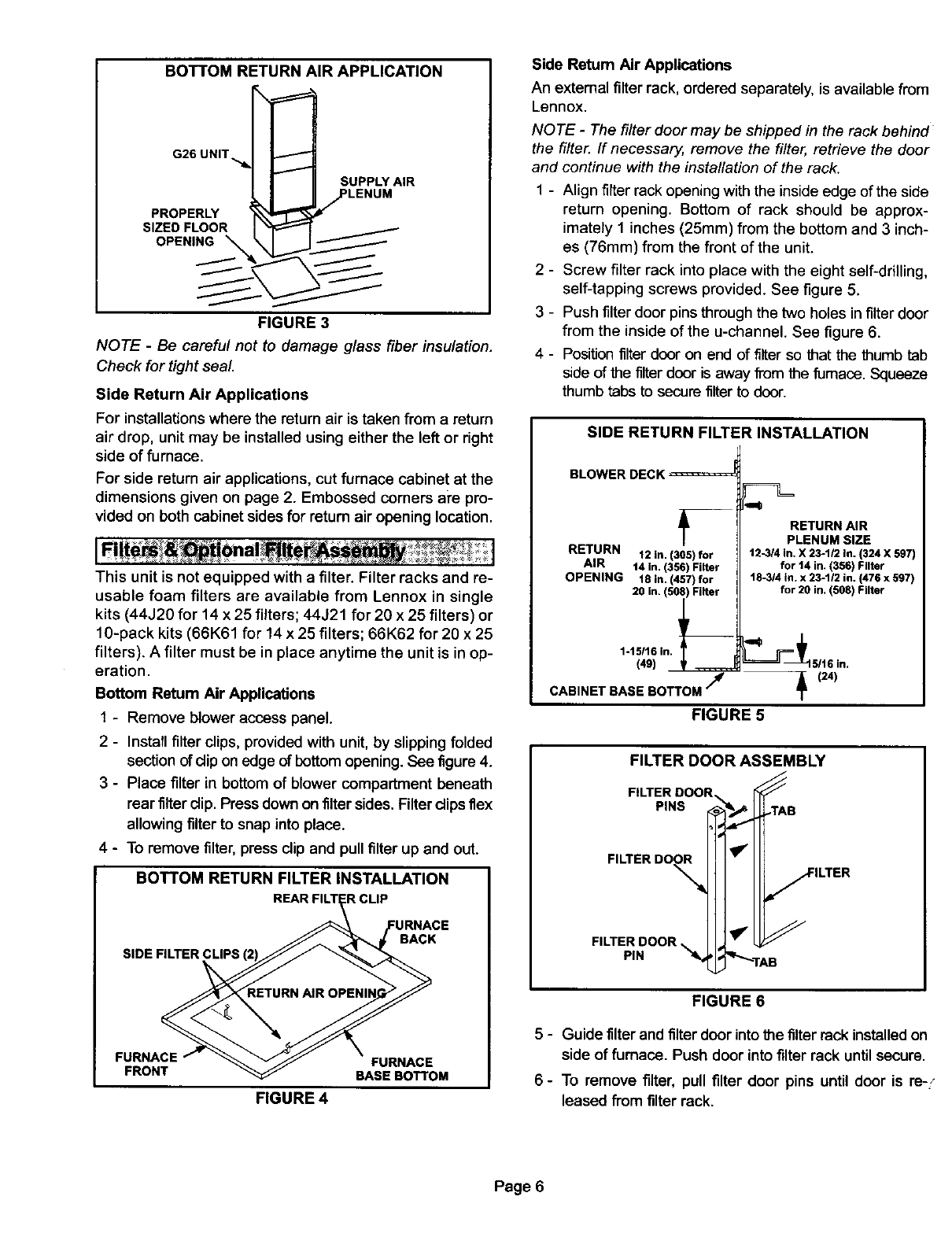
BOTTOM RETURN AIR APPLICATION
G26 UNIT._I_
I I SUPPLYAIR
kl _-J/LENUM
PROPERLY "iX_
SIZED FLOOR I _
OPENING\ \1
FIGURE 3
NOTE - Be careful not to damage glass fiber insulation.
Check for tight seal.
Side Return Air Applications
For installationswhere the return air is taken from a return
air drop, unit may be installed using either the left or right
side of furnace.
For side return air applications, cut furnace cabinet at the
dimensions given on page 2. Embossed corners are pro-
vided on both cabinet sides for return air opening location.
This unit is not equipped with a filter. Filter racks and re-
usable foam filters are available from Lennox in single
kits (44J20 for 14 x 25 filters; 44J21 for 20 x 25 filters) or
10-pack kits (66K61 for 14 x 25 filters; 66K62 for 20 x 25
filters). A filter must be in place anytime the unit is in op-
eration.
Bottom Return Air Applications
1-Remove blower access panel.
2-Install filter clips, provided with unit, by slipping folded
section of clipon edge of bottom opening. See figure 4.
3-Place filter in bottom of blower compartment beneath
rear filterdip. Press down on filter sides. Filterclipsflex
allowing filter to snap into place.
4-To remove filter, press clip and pullfilter up and out.
BOTTOM RETURN FILTER INSTALLATION
SIDE FILTER CLIPS
BACK
FURNACE FURNACE
FRONT BASE BOTTOM
FIGURE 4
Side Retum Air Applications
An external filter rack, ordered separately, is available from
Lennox.
NOTE -The filter door may be shipped in the rack behind
the filter. If necessary, remove the filter, retrieve the door
and continue with the installation of the rack.
1 - Align filter rack opening with the inside edge of the side
return opening. Bottom of rack should be approx-
imately 1 inches (25mm) from the bottom and 3 inch-
es (76mm) from the front of the unit.
2 - Screw filter rack into place with the eight self-drilling,
self-tapping screws provided. See figure 5.
3 - Push filter door pins through the two holes in filter door
from the inside of the u-channel. See figure 6.
4 - Position filter door on end of filter so that the thumb tab
side of the filter door is away from the fumace. Squeeze
thumb tabs to secure filter to door.
SIDE RETURN FILTER INSTALLATION
BLOWER DECK
L
RETURN 12 In. (305) for
AIR 14 in. (356) Filter
OPENING 18 in. (457) for
20 in, (508) Filter
1-15/16(49)in, _
CABINET BASE BOTTOM "/4
RETURN AIR
PLENUM SIZE
t2-3/4 in. X 23-1/2 in. (324 X 597)
for t4 in. (356) Filter
18-3/4 in. x 23-1/2 in. {476 x 597)
for 20 in. (508) Filter
FIGURE 5
FILTER DOOR ASSEMBLY
FILTERDOOR,
PINS
FILTER DO_
FILTER DOOR
PIN _4,
B
ILTER
FIGURE 6
5-Guide tilter and filterdoor into the filterrack installed on
side of furnace. Push door into filter rack untilsecure.
6 - To remove filter, pull filter door pins until door is re-.-
leased from filter rack.
Page 6
Useindustry-approvedstandardsto sizeandinstallthe
supplyandreturnairductsystem.Thiswillresultinaquiet
andlow-static system that has uniform air distribution.
Supply Air Plenum
Furnaces installed without a cooling coil require the installa-
tion of a removable access panel in the supply air duct. The
access panel should be large enough to permit inspection (ei-
ther by smoke or reflected light) of the heat exchanger for
leaks after installation. The furnace access panel must al-
ways be in place when the furnace is operating and it must
not allow leaks into the supply air duct system.
Return Air Plenum
See dimension illustration on page 2 for proper return air
duct size.
NOTE -For bottom return air, return air duct should be se-
cured to the unit using rivets or S-locks. For side return air,
secure return air duct to filter rack using screws. When us-
ing screws, take care to avoid interference with the filter
which may cause improper filtration.
The return air must not be drawn from a room where
another gas appliance (ie., a water heater) is installed.
Even though this furnace draws its combustion air from
outside of the structure, other gas appliances that share a
utility room may not, When return air is drawn from a room,
a negative pressure is created in the room. If a gas ap-
pliance is operating in a room with negative pressure, the
flue products can be pulled back down the vent pipe and
into the room. This reverse flow of the flue gas may result in
incomplete combustion and the formation of carbon mon-
oxide gas. This toxic gas might then be distributedthrough
the house by the furnace duct system.
I A CAUTION I
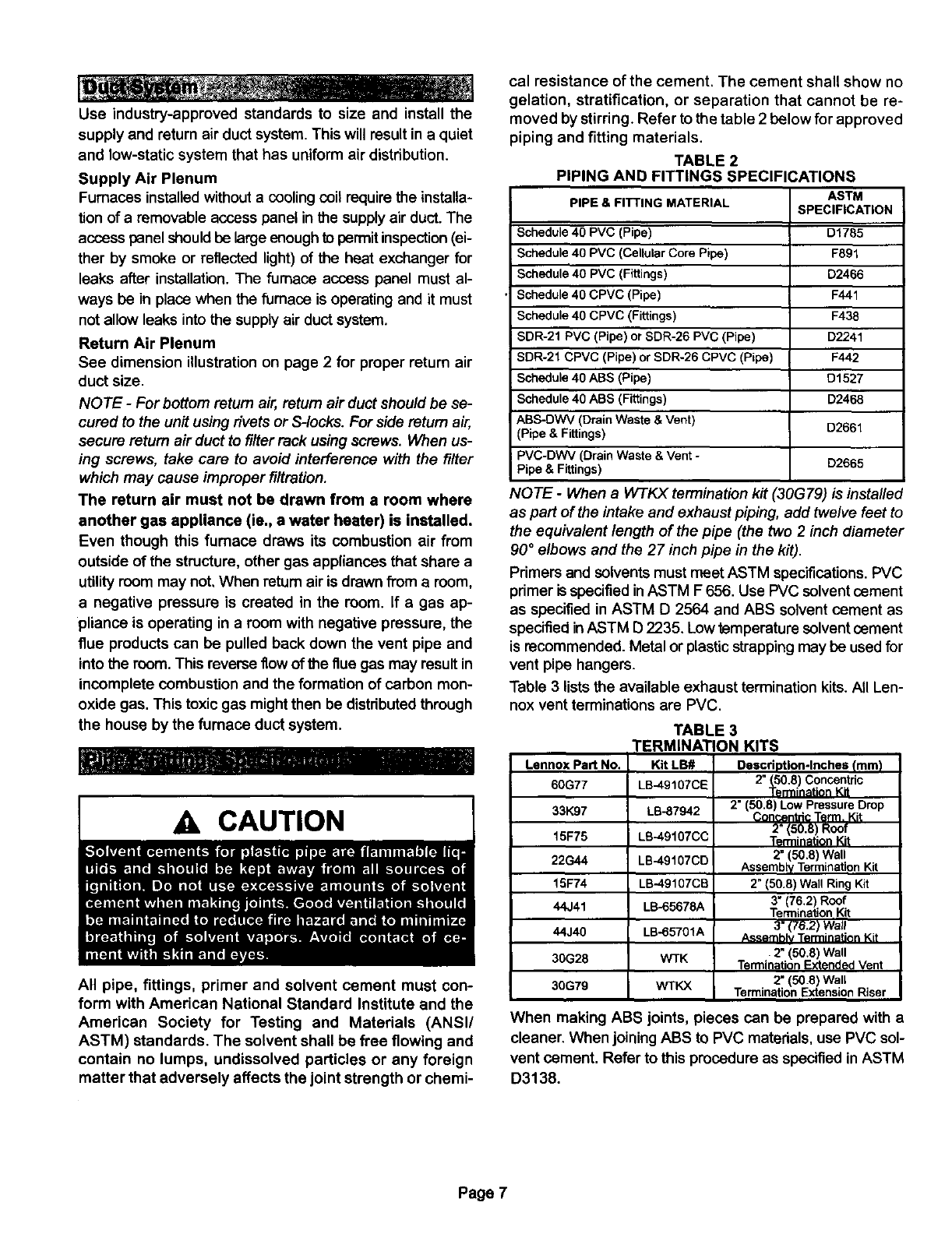
All pipe, fittings, primer and solvent cement must con-
form with American National Standard Institute and the
American Society for Testing and Materials (ANSI/
ASTM) standards. The solvent shall be free flowing and
contain no lumps, undissolved particles or any foreign
matter that adversely affects the joint strength or chemi-
cal resistance of the cement. The cement shall show no
gelation, stratification, or separation that cannot be re-
moved by stirring. Refer to the table 2 below for approved
piping and fitting materials.
TABLE 2
PIPING AND FITTINGS SPECIFICATIONS
PIPE & FITTING MATERIAL
Schedule 40 PVC (Pipe)
Schedule 40 PVC (Cellular Core Pipe)
Schedule 40 PVC (Fittings)
Schedule 40 CPVC (Pipe)
Schedule 40 CPVC (Fittings)
SDR-21 PVC (Pipe) or SDR-26 PVC (Pipe)
SDR-21 CPVC (Pipe) or SDR-26 CPVC (Pipe)
Schedule 40 ABS (Pipe)
Schedule 40 ABS (Fittings)
ABS-DWV (Drain Waste & Vent)
(Pipe & Fittings)
PVC-DWV (Drain Waste & Vent -
Pipe & Fittings)
ASTM
SPECIFICATION
D1785
F891
D2466
F441
F438
D2241
F442
D1527
D2468
D2661
D2665
NOTE -When a W-I'KX termination kit (30G79) is installed
as part of the intake and exhaust piping, add twelve feet to
the equivalent length of the pipe (the two 2inch diameter
90 °elbows and the 27 inch pipe in the kit).
Primers and solvents must meet ASTM specifications.PVC
primer is specified in ASTM F 656. Use PVC solvent cement
as specified in ASTM D 2564 and ABS solvent cement as
specified in ASTM D2235. Low temperature solvent cement
is recommended. Metal or plastic strapping may be used for
vent pipe hangers.
Table 3 lists the available exhaust termination kits. All Len-
nox vent terminations are PVC.
Lennox Pad No.
60G77
33K97
15F75
22G44
15F74
44J41
44J40
30G28
30G79
TABLE 3
TERMINATION KITS
Kit LB# Description-Inches (mm)
2" (50,8) Concentric
LB-49107CE _rmin_tion Kit
LB-87942 2" (50.8) Low Pressure Drop
Con_-_ntricTerm. Kit
2" 50.8) Roof
LB-4gl07CC Tgf nination Kit
LB-49107CD 2" (50.8) Wall
Assembly Termination Kit
LB-49107CB 2" (50.8) Wall Ring Kit
3" 76.2) Roof
LB-65678A Termination K t
LB-65701A 3" (7S.2) Wall
/L_rnhlv Terminatinn Kit
WTK •2" (50.8) Wall
Termination Extended Vent
2" (50.8) Wall
WTKX Termination Extension Riser
When making ABS joints, pieces can be prepared with a
cleaner. When joining ABS to PVC matedals, use PVC sol-
vent cement. Refer to this procedure as specified inASTM
D3138.
Page 7
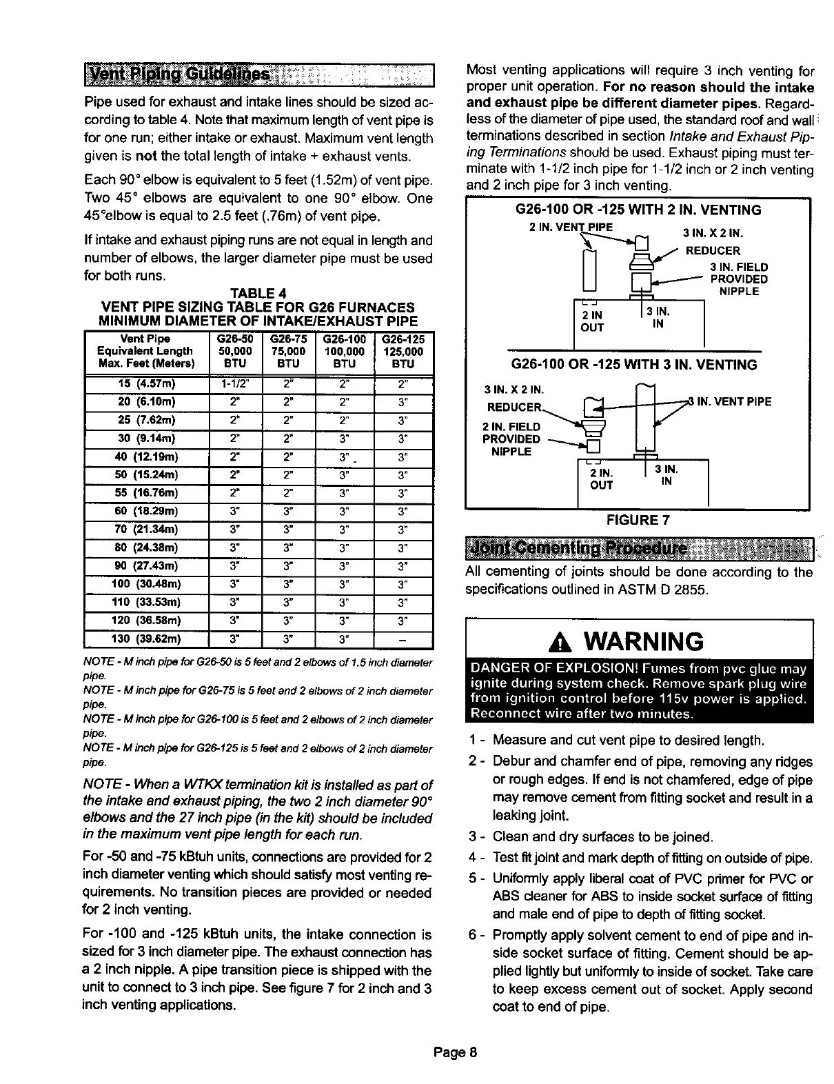
Pipe used for exhaust and intake lines should be sized ac-
cording to table 4. Note that maximum length of vent pipe is
for one run; either intake or exhaust. Maximum vent length
given is not the total length of intake + exhaust vents.
Each 90 ° elbow is equivalent to 5 feet (1.52m) of vent pipe.
Two 45 ° elbows are equivalent to one 90 ° elbow. One
45°elbow is equal to 2.5 feet (.76m) of vent pipe.
If intake and exhaust piping runs are not equal in length and
number of elbows, the larger diameter pipe must be used
for both runs.
TABLE 4
VENT PIPE SIZING TABLE FOR G26 FURNACES
MINIMUM DIAMETER OF INTAKE/EXHAUST PIPE
Vent Pipe G26-50 G26-75 G26-100 G26-125
Equivalent Length 50,000 75,000 100,000 125,000
Max, Feet (Meters) BTU BTU BTU BTU
15 (4.57m) 1-1/2" 2" 2" 2"
20 (6.10m) 2" 2" 2" 3"
25 (7.62m) 2" 2" 2" 3"
30 (9.14m) 2" 2" 3" 3"
40 (12.19m) 2" 2" 3" 3"
50 (15.24m) 2" 2" 3" 3"
55 (16,76m) 2" 2" 3" 3"
60 (10.29m) 3" 3" 3" 3"
70 (21.34m) 3" 3" 3" 3"
80 (24.38m) 3" 3" 3°3"
90 (27.43m) 3" 3" 3" 3"
100 (30.48m) 3" 3" 3" 3"
110 (33.53m) 3" 3" 3" 3"
120 (36.58m) 3" 3" 3" 3"
130 (39.62m) 3" 3" 3" -
NOTE -M inchpipe forG26-50is 5 feet and2 elbowsof 1.5inch diameter
pipe.
NOTE -M inchpipe forG26-75 is 5 feetand 2 elbowsof 2 inchdiameter
pipe.
NOTE -M inchpipe forG26-100is 5 feetand2 elbows of 2 inchdiameter
pipe.
NOTE -M inchpipe for G26-125 is 5 feetand2 elbowsof 2 inchdiameter
pipe.
NOTE -When a WTtO( termination kit is installed as part of
the intake and exhaust piping, the two 2 inch diameter 90 °
elbows and the 27 inch pipe (in the kit) should be included
in the maximum vent pipe length for each run.
For -50 and -75 kBtuh units, connections are provided for 2
inch diameter venting which should satisfy most venting re-
quirements. No transition pieces are provided or needed
for 2 inch venting.
For -100 and -125 kBtuh units, the intake connection is
sized for 3 inch diameter pipe. The exhaust connection has
a 2 inch nipple. Apipe transition piece is shipped with the
unit to connect to 3 inch pipe. See figure 7 for 2 inch and 3
inch venting applications.
Most venting applications will require 3 inch venting for
proper unit operation. For no reason should the intake
and exhaust pipe be different diameter pipes. Regard-
less of the diameter of pipe used, the standard roof and wall i
terminations described in section Intake and Exhaust Pip-
ing Terminations should be used. Exhaust piping must ter-
minate with 1-1/2 inch pipe for 1-1/2 inch or 2 inch venting
and 2 inch pipe for 3 inch venting.
G26-100 OR -125 WITH 2 IN. VENTING
2 IN. VEN'_,,._P_ ¢,..1 3 IN. X2 IN.
I-1" /REDU'%E'D
I I _PROVIDED
2IN I 3IN'
OUT IN
G26-100 OR -125 WITH 3 IN. VENTING
31N. X21N.
REDUCER _IN. VENT PIPE
2,N IV
PROVIDED _II
NIPPLE 2IN. I 3IN.
OUT IN
FIGURE 7
All cementing of joints should be done according to the
specifications outlined in ASTM D 2855.
1 - Measure and cut vent pipe to desired length.
2 - Debur and chamfer end of pipe, removing any ridges
or rough edges. If end is not chamfered, edge of pipe
may remove cement from fitting socket and result in a
leaking joint.
3 - Clean and dry surfaces to be joined.
4 - Test fitjoint and mark depth of fitting on outside of pipe.
5 - Uniformly apply liberal coat of PVC primer for PVC or
ABS cleaner for ABS to inside socket surface of fitting
and male and of pipe to depth of fittingsocket.
6 - Promptly apply solvent cement to end of pipe and in-
side socket surface of fitting. Cement should be ap-
plied lightly but uniformly to inside of socket. Take care
to keep excess cement out of socket. Apply second
coat to end of pipe.
Page 8
NOTE - -iTmeis cdtical at this stage. Do not allow pnm-
er to dry before applying cement.
7- Immediately after applying last coat ofcement to pipe,
and while both inside socket surface and end of pipe
are wet with cement, forcefully insert end of pipe into
socket until it bottoms out. Tum pipe 1/4 turn dudng as-
sembly (but not after pipe is fully inserted) to distribute
cement evenly.
NOTE-Assembly should be completed within 20 sec-
onds after last application of cement. Hammer blows
should not be used when inserting pipe.
8 - After assembly, wipe excess cement from pipe at end
of fitting socket. A properly made joint will show a
bead around its entire perimeter. Any gaps may indi-
cate a defective assembly due to insufficient solvent.
9 - Handle joints carefully until completely set.
The thickness of construction through which vent/air intake
pipes may be installed is a minimum of 3 inches (610 mm),
and a maximum of 24 inches (610mm). If a G26 furnace re-
places a fumace which was commonly vented with another
gas appliance, the size of the existing vent pipe for that gas
appliance must be checked. Without the heat of the odginal
furnace flue products, the existing vent pipe is probably
oversized for the single water heater or other appliance.
The vent should be checked for proper draw with the re-
maining appliance.
1 - Cement intake piping in slip connector located at top
of unit.
2 - Route piping to outside of structure. Continue with
installation following instructions given in exhaust and
intake piping termination section.
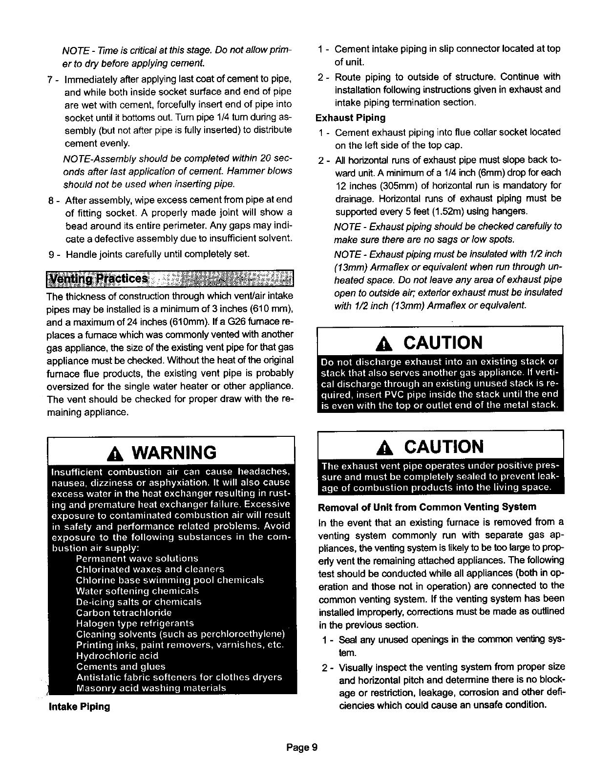
Exhaust Piping
1 - Cement exhaust piping into flue collar socket located
on the left side of the top cap.
2 - All horizontal runs of exhaust pipe must slope back to-
ward unit. A minimum of a 1/4 inch (6mm) drop for each
12 inches (305mm) of horizontal run is mandatory for
drainage. Horizontal runs of exhaust piping must be
supported every 5 feet (1.52m) using hangers.
NOTE -Exhaust piping should be checked carefully to
make sure there are no sags or low spots.
NOTE -Exhaust piping must be insulated with 1/2 inch
(13mm) Armaflex or equivalent when run through un-
heated space. Do not leave any area of exhaust pipe
open to outside air; exterior exhaust must be insulated
with 1/2 inch (13mm) Armaflex or equivalent.
A WARNING
Intake Piping
CAUTION
Removal of Unit from Common Venting System
In the event that an existing furnace is removed from a
venting system commonly run with separate gas ap-
pliances, the ventingsystem is likelyto be too large to prop-
edy vent the remaining attached appliances. The following
test should be conducted while all appliances (both in op-
eration and those not in operation) are connected to the
common venting system. If the venting system has been
installed improperly, corrections must be made as outlined
in the previous section.
1-Seal any unused openingsin the common ventingsys-
tem.
2 - Visually inspect the venting system from proper size
and horizontal pitch and determine there is no block-
age or restdction, leakage, corrosion and other deft-
ciencies which could cause an unsafe condition.
Page 9
3- Close all building doors and windows and all doors be-
tween the space in which the appliances remaining
connected to the common venting system are located
and other spaces of the building.Turn on clothes dry-
ers and any appliances notconnected to the common
venting system. Turn on any exhaust fans, such as
range hoods and bathroom exhausts, so they will op-
erate at maximum speed. Do not operate a summer
exhaust fan. Close fireplace dampers.
4 - Follow the lightinginstruction.Place the appliance be-
ing inspected in operation. Adjust thermostat so ap-
pliance will operate continuously.
5 - Test for spillage at the draft hood relief opening after 5
minutes of main burner operation. Use the flame of a
match or candle, or smoke fl'om a cigarette, or a cigar.
6- After you have determined that each appliance re-
maining connected to the common venting system
properly vents when tested as outlined above, return
doom, windows, exhaust fans, fireplace dampers and
any other gas-burning appliance to their previous con-
dition of use.
7- If improper venting is observed during any of the
above tests, the common venting system must be cor-
rected. The common venting system should be re-
sized to approach the minimum size as determined by
using the appropriate tables in appendix G in the cur-
rent standards of the National Fuel Gas Code ANSI
Z223-1 in the U.S.A., and the appropdate Category 1
Natural Gas and Propane appliances venting sizing
tables in the current standards of the CAN/
CGA-B149.1 and .2 in the Natural Gas and Propane
Installation Code in Canada.
Intake and Exhaust Piping Terminations
Intake and exhaust pipes may be routed either horizontally
through an outside wall or vertically through the roof. In at-
tic or closet installations, vertical termination through the
roof is preferred. Figures 8 through 20 show typical ter-
minations.
1-Use recommended piping materials for both intake
and exhaust piping.
2 - Secure all joints, including drain leg, gas tight using
approved cement.
3-Piping diameters should be determined according to
length of pipe run. See table 4. Locate intake piping
upwind (prevailingwind) from exhaust piping. To avoid
re-circulation of exhaust gas on roof terminations, end
of exhaust pipe must be higher than intake pipe.
Exhaust and intake exits must be in same pressure
zone. Do not exit one through the roof and one on the
side. Also, do not exit the intake on one side and the
exhaust on another side of the house or structure.
4-
5-
Intake and exhaust pipes should be placed as close
together as possible at termination end (refer to il-
lustrations). Maximum separation is 3 inches (76mm) ,-
on roof terminations and 6 inches (152mm) on side
wall terminations.
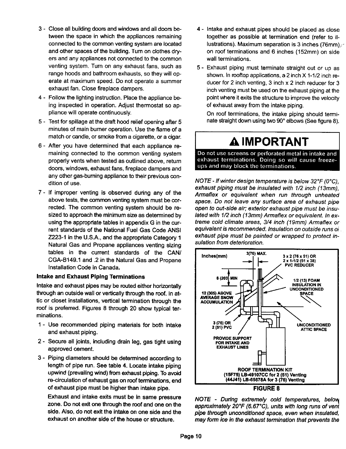
Exhaust piping must terminate straight out or up as
shown. In rooftop applications, a 2 inch X 1-1/2 inch re-
ducer for 2 inch venting, 3 inch x 2 inch reducer for 3
inch venting must be used on the exhaust piping at the
point where it exits the structure to improve the velocity
of exhaust away from the intake piping.
On roof terminations, the intake piping should termi-
nate straight down using two 90° elbows (See figure 8).
A IMPORTANT
NOTE -If winter design temperature is below 32°F (O°C),
exhaust piping must be insulated with 1/2 inch (13mm),
Armaflex or equivalent when run through unheated
apace. Do not leave any surface area of exhaust pipe
open to out-side air; exterior exhaust pipe must be insu-
lated with I/2 inch (13mm) Armaflex or equivalent. In ex-
treme cold climate areas, 3/4 inch (19mm) Armaflex or
equivalent is recommended. Insulation on outside runs oi
exhaust pipe must be painted or wrapped to protect in-
sulation from deterioration.
Inches(mm) 3(76 MAX.__ 3 x 2 (76 x 51) OR
_2 x 1-1/2 (51 x38)
/PVC REDUCER
8 (203I MIN 1/2 (13) FOAM
INSULATION IN
UNCONDITIONED
12 (305) ABOVE SPACE
AVE"*OESNOW
ACCUMULATION
3 (76) OR UNCONDITIONED
2 (51) PVC ATTIC SPACE
PROVIDE SUPPORT
FOR INTAKE AND
EXHAUST LINES
ROOF TERMINATION KIT
(15F75) LB-49107CC for 2 (51) Venting
(44J41) LB-65678A for 3 (76) Venting
FIGURE 8
NOTE -Dudng extremely cold temperatures, belov_
approximately 20°F (6.67°C), units with long runs of venl
pipe through unconditioned space, even when insulated,
may form ice in the exhaust termination that prevents the
Page 10
unit from operating properly. Longer run times of at least 5
minutes will alleviate most icing problems. Also, a heating
cable may be installed on exhaust piping and termination to
prevent freeze-ups. Heating cable installation kit is avail-
able from Lennox. See Condensate Piping section for part
numbers.
NOTE -Care must be taken to avoid recirculation of ex-
haust back into intake pipe.
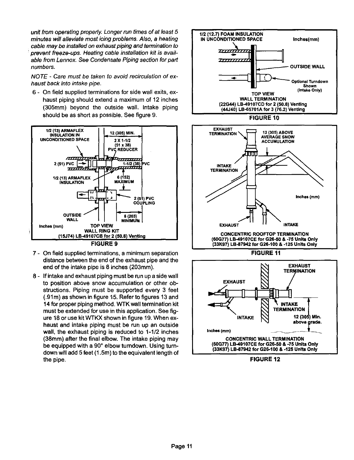
6 - On field supplied terminations for side wall exits, ex-
haust piping should extend a maximum of 12 inches
(3O5mm) beyond the outside wall. Intake piping
should be as short as possible. See figure 9.
1/2 (13) ARMAFLEX
INSULATION IN
UNCONDITIONED SPACE
12 (305) MIN.
2 X 1-1/2
(51x 38)
1-1/2 30 _VC
2(011 _ 0(J02)
1/2 (13) ARMAFLEX I
INSULATION MAXIMUM
Z2 21_ PVC
COUPLING
OUTSlOEJ
WALL MINIMUM [
Inches (ram) TOP VIEW
WALL RING KiT
(15J74) LB-49107CB for 2 (50.8) Venting
FIGURE 9
7 - On field supplied terminations, a minimum separation
distance between the end of the exhaust pipe and the
end of the intake pipe is 8 inches (203mm).
8- If intake and exhaust piping must be run up a side wall
to position above snow accumulation or other ob-
structions. Piping must be supported every 3 feet
(.91m) as shown in figure 15. Refer to figures 13 and
14 for proper piping method. WTK wall termination kit
must be extended for use in this application. See fig-
ure 18 or use kit WTKX shown in figure 19. When ex-
haust and intake piping must be run up an outside
wall, the exhaust piping is reduced to 1-1/2 inches
(38ram) after the final elbow. The intake piping may
be equipped with a 90° elbow turndown. Using turn-
down will add 5 feet (1.5m) to the equivalent length of
the pipe.
112 (12.7) FOAM INSULATION
IN UNCONDITIONED SPACE Inches(mm)
Optional Turndown
Shown
(Intake Only)
TOP VIEW
WALL TERMINATION
(22G44) LB49107CD for 2 (50.8) Venting
(44J40) LB-65701A for 3 (76.2) Venting
FIGURE 10
EXHAUST
TERMINATION _ _ 12 (305) ABOVE
AVERAGE SNOW
ACCUMULATION
_INTAKE
TERMINATION
F.XHAUST INTAKE
CONCENTRIC ROOFTOP TERMINATION
(60G77) LB49107CE for G26-50 & -75 Units Only
(33K07) LB-87942 for G26-t00 & -125 Units Only
FIGURE 11
EXHAUST
Inches (mm)
EXHAUST
INATION
TERMINATION I
12(305)Mln,
CONCENTRIC WALL TERMINATION
(60G77) LB-49107CE for G26-50 & -75 Units Only
(33K97) LB-87942 for G26-100 & -t25 Units Only
FIGURE 12
Page 11
Inches(ram)
UNCONDITIONED
SPACE
12 (305) MIN. for 2 (51)
20 (508) MAX. for 3 (75)I
OUTSIDE WALL
PROVIDE SUPPORT 12 A
FOR INTAKE AND
EXHAUST LINES EVERY BOVE
36 (914) AVERAGE SNOW
ACCUMULATION
/
1/2 (13) FOAM
INSULATION IN --
UNCONDITIONED 1/2 (13) FOAM
SPACE INSULATION
SIDE VIEW
WALL RING TERMINATION
(15F74)LB-49107CBfor2 in.(51)Venting
"This reducer is not necessary for G26-50 units using 1-1/2 In. venting,
See venting table 4 for maximum venting lengths with this arrangement.
FIGURE 13
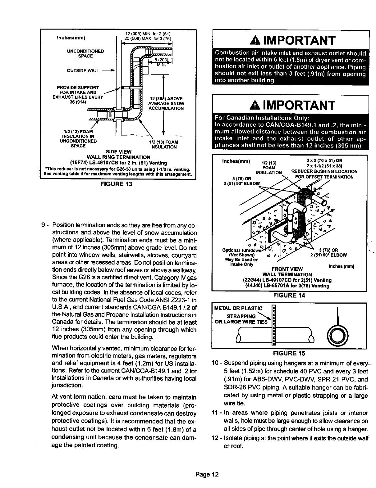
g-Position terminationends so they are flee from any ob-
structions and above the level of snow accumulation
(where applicable). Termination ends must be a mini-
mum of 12 inches (305mm) above grade level. Do not
point into window wells, stairwells, alcoves, courtyard
areas or other recessed areas. Do notpositiontermina-
tion ends directlybelow roofeaves or above a walkway.
Since the G26 is acertified direct vent, Category IV gas
furnace, the location of the termination is limited by lo-
cal building codes. In the absence of local codes, refer
to the current National Fuel Gas Code ANSI Z223-1 in
U.S.A., and current standards CAN/CGA-B149.1/.2 of
the Natural Gas and Propane Installation Instructions in
Canada for details. The termination should be at least
12 inches (305mm) from any opening through which
flue products could enter the building.
When horizontally vented, minimum clearance for ter-
mination from electric meters, gas meters, regulators
and relief equipment is 4 feet (1.2m) for US installa-
tions. Refer to the current CAN/CGA-B149.1 and .2 for
installations in Canada or with authoritieshaving local
jurisdiction.
At vent termination, care must be taken to maintain
protective coatings over building materials (pro-
longed exposure to exhaust condensate can destroy
protective coatings). It is recommended that the ex-
haust outlet not be located within 6 feet (1.8m) of a
condensing unit because the condensate can dam-
age the painted coating.
A IMPORTANT
A IMPORTANT
Inches(mm) 1/2 (13)
FOAM
iNSULATION
3(75)OR
2 (51) 90 °ELBOW
3x2(76x51) OR
2x 1-1/2(51 x 38)
REDUCER BUSHING LOCATION
FOR OFFSET TERMINATION
e
3(75)OR
(NOt Shown) _t _, 2 (51) 90 °ELBOW
May Be Used on
Intake Only Inches (mm)
FRONT VIEW
WALL TERMINATION
(22G44) LD-49107CD for 2(51) Venting
(44,140) LB-65701A for 3(76) Venting
FIGURE 14
METAL OR PLASTIC
STRAPPING _,_
OR LARGE WIRE TIES
FIGURE 15
10 - Suspend pipingusing hangers at a minimum of every-
5 feet (1.52m) for schedule 40 PVC and every 3 feet
(.91m) for ABS-DWV, PVC-DWV, SPR-21 PVC, and
SDR-26 PVC piping. A suitable hanger can be fabri-
cated by using metal or plastic strapping or a large
wire tie.
11 - In areas where piping penetrates joists or interior
walls, hole must be large enough to allow clearance on
all sides of pipe through center of hole using a hanger.
12 - Isolate pipingat the pointwhere it exits the outsidewall
or roof.
Page 12
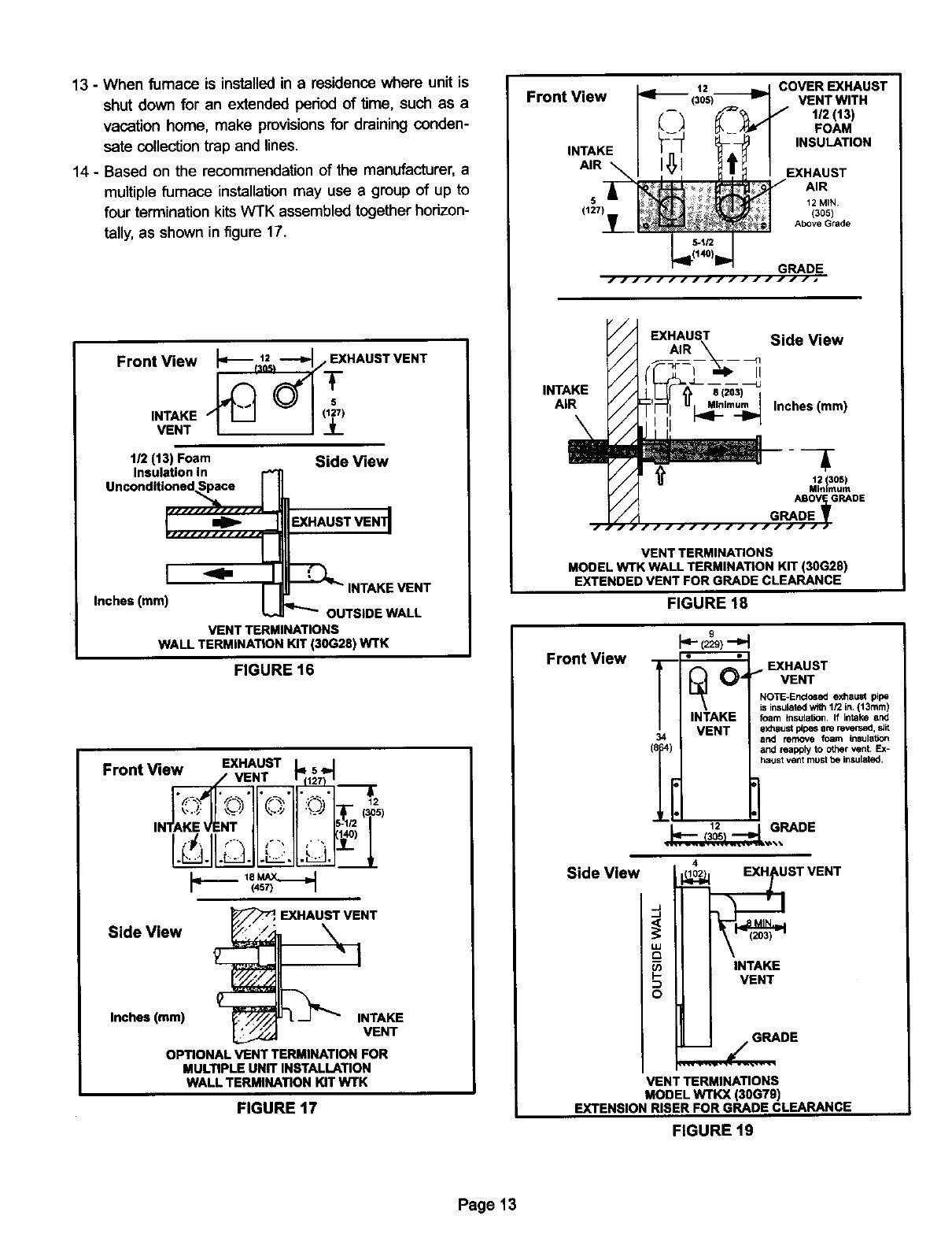
13 -When furnace is installed in a residence where unit is
shut down for an extended peded of time, such as a
vacation home, make provisions for draining conden-
sate collection trap and lines.
14 - Based on the recommendation of the manufacturer, a
multiple furnace installation may use a group of up to
four termination kits WTK assembled together horizon-
tally, as shown in figure 17.
Front View Iq_ 1_5,-_/ EXHAUSTVENT
VENT
1/2 (13) Foam f
Inches (mini E
VENTTERMINATIONS
WALLTERMINATIONKIT(30G28) WTK
Side View
EXHAUST VEN_
INTAKE VENT
OUTSIDE WALL
FIGURE 16
Front View EXHAUST
p--- I
12
EXHAUST VENT
Side View ':" :/"
Inches (ram) _NTAKE
_ VENT
OPTIONAL VENT TERMINATION FOR
MULTIPLE UNIT INSTALLATION
WALL TERMINATION KITWTK
FIGURE 17
Front View
INTAKE
AIR
(127) _
12
(3os) COVEREXHAUST
VENT WITH
112 (13)
FOAM
INSULATION
EXHAUST
AIR
12 MIN
(305)
AbOveGrade
INTAKE
AIR
/ / Side View
/ /
/ / ----_n II
//// U_im_ Inches (ram)
//
/ / 12 305
/ / Mnmum
ABOV_GRADE
/ / GRADE
_JIIIIIIIIIIIIIII
VENT TERMINATIONS
MOOEL WTK WALL TERMINATION KIT (30G28)
EXTENDED VENT FOR GRADE CLEARANCE
Front View
FIGURE 18
T
34
I'- -'I
0,,_ _. EXHAUSTvENT
NOTE-Enclosed exhaust pipe
is insulated with 1/2 in, (13ram)
INTAKE foam Insulatfon. ff intake and
VENT exhaustpipe8arerev,,._,s_
and remove foam insulation
and reapply to other vent. Ex-
haust vent must be insulated.
12 _ GRADE
...l_'::_J_.._.. ,,,
Side View 4
STVENT
°°
VENT TERMINATIONS
MODEL w'rKx (30G79)
EXTENSION RISER FOR GRADE CLEARANCE
FIGURE 19
Page 13
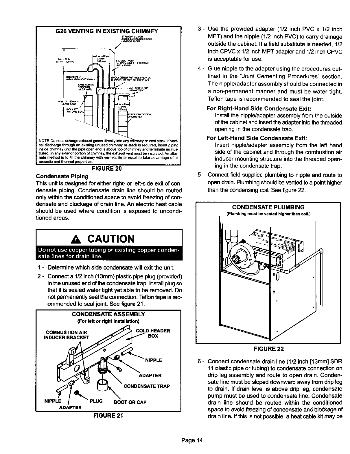
G26 VENTING IN EXISTING CHIMNEY
c_x1_ n_r
or vent stack. If verti-
cal discharge through an existing unused chimney or stack is required, insertpiping
inside chimney un_lthe pipeopen end is above top of chimney and terminate as illuS-
trated. In any exteriorper6on of chimney, Itm exhaust vent mustbe insulated. An aHer-
hate method is to fill the chimney w_h ¥emliculita or equal to take advantage of its
acoustic and thermal properties.
FIGURE 20
Condensate Piping
This unit is designed for either dght- or left-side exit of con-
densate piping. Condensate drain line should be routed
only within the conditioned space to avoid freezing of con-
densate and blockage of drain line, An electric heat cable
should be used where condition is exposed to uncondi-
tioned areas.
A CAUTION
1 - Determine which side condensate will exit the unit.
2 - Connect a 1/2 inch (13mm) plastic pipe plug (provided)
inthe unused end ofthe condensate trap, Installplug so
that it is sealed water tight yet able to be removed. Do
not permanently seal the connection. Teflontape is rec-
ommended to seal joint. See figure 21.
CONDENSATE ASSEMBLY
(Forleftor rlghtInstallation)
COMBUSTION AIR
INDUCER BRACKET
COLD HEADER
BOX
NIPPLE
ADAPTER
NIPPLE
ADAPTER
CONDENSATE TRAP
PLUG BOOT OR CAP
FIGURE 21
3- Use the provided adapter (1/2 inch PVC x 1/2 inch
MPT) and the nipple (1/2 inch PVC) to carry drainage
outside the cabinet. If a field substitute is needed, 1/2
inch CPVC x 1/2 inch MPT adapter and 1/2 inch CPVC
is acceptable for use.
4 - Glue nipple to the adapter using the procedures out-
lined in the "Joint Cementing Procedures" section.
The nipple/adapter assembly should be connected in
a non-permanent manner and must be water tight.
Teflon tape is recommended to seal the joint.
For Right-Hand Side Condensate Exit:
Install the nipple/adapter assembly from the outside
of the cabinet and insert the adapter into the threaded
opening in the condensate trap.
For Left-Hand Side Condensate Exit:
Insert nipple/adapter assembly from the left hand
side of the cabinet and through the combustion air
inducer mounting structure into the threaded open-
ing in the condensate trap.
5-Connect field supplied plumbingto nipple and route to
open drain. Plumbing shouldbe vented to a pointhigher
than the condensing coil. See figure 22.
CONDENSATE PLUMBING
(Plumbing must be vented higher than coil.)
_
FIGURE 22
Connect condensate drain line (1/2 inch [13mm] SDR
11 plastic pipe or tubing) to condensate connection on
drip leg assembly and route to open drain. Conden-
sate line must be sloped downward away from drip leg
to drain. If drain level is above drip leg, condensate
pump must be used to condensate line. Condensate
drain line should be routed within the conditioned
space to avoid freezing of condensate and blodkage of
drain line. If this is not possible, a heat cable kit may be
Page 14
used on the condensate drip leg and line. Heating
cable kit is available from Lennox in various lengths;
6feet (1.8m) - kit no. 18K48; 24 feet (7.3m) - kit no.
18K49; and 50 feet (15.2m) - kit no. 18K50.
..... I
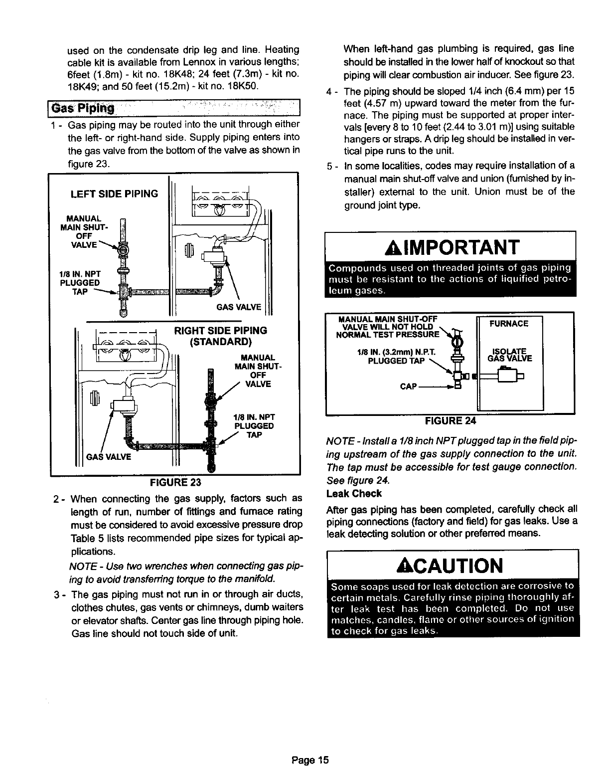
1 - Gas piping may be routed into the unit through either
the left- or right-hand side. Supply piping enters into
the gas valve from the bottom of the valve as shown in
figure 23.
LEFT SIDE PIPING
MANUAL
MAIN SHUT-
OFF
VALVE
1/8 IN. NPT
PLUGGED
TAP _I_, _
GAS VALVE
_ .... _ RIGHT SIDE PIPING
___ _=_L_ (STANDARD)
_' _=" 1/8 IN. NPT
/BPLUGGED
//TAP
GAS VALVE
FIGURE 23
2- When connecting the gas supply, factors such as
length of run, number of fittings and furnace rating
must be considered to avoid excessive pressure drop
Table 5 lists recommended pipe sizes for typical ap-
plications.
NOTE- Use two wrenches when connecting gas pip-
ing to avoid transferring torque to the manifold.
3 - The gas piping must not run in or through air ducts,
clothes chutes, gas vents or chimneys, dumb waiters
or elevator shafts. Center gas line through pipinghole.
Gas line should not touch side of unit.
4-
5-
When left-hand gas plumbing is required, gas line
should be installedin the lower half of knockoutso that
piping will clear combustion air inducer.See figure 23.
The pipingshould be sloped 1/4 inch (6.4 ram) per 15
feet (4.57 m) upward toward the meter from the fur-
nace. The piping must be supported at proper inter-
vals [every 8 to 10 feet (2.44 to 3.01 m)] using suitable
hangers or straps. Adrip leg should be installed inver-
tical pipe runs to the unit.
In some localities, codes may require installation of a
manual main shut-offvalve and union(furnished by in-
staller) external to the unit. Union must be of the
ground joint type.
AIMPORTANT
HO"A' ES'P"E"O"EII
118IN.13.2mmlN.P.T.1_. II ISOLATE
/|
FIGURE 24
NO TE -Install a 1/8 inch NPT plugged tap in the field pip-
ing upstream of the gas supply connection to the unit.
The tap must be accessible for test gauge connection.
See figure 24.
Leak Check
After gas piping has been completed, carefully check all
piping connections (factory and field) for gas leaks. Use a
leak detecting solution or other preferred means.
ACAUTION
Page 15

Nominal
Iron Pipe Size
-Inches(mm)
1/4
(6.35)
3/8
(9.53)
1/2
(12.7)
3/4
(19.05)
1
(25.4)
1-1/4
(31.75)
1-1/2
(36.1)
2
(50.8)
2-1/2
(63.5)
3
(76.2)
4
(101.6)
TABLE 5
GAS PIPE CAPACITY -FT31HR (kL/HR)
Internal Length of Pipe-Feet(m)
Diameter 10 20 30 40 50 60 70
-Inches(mm) (3,048) (6.096) (9.144) (12.192) (15.240) (18.288) (21.336)
364
(9.246)
.493
(12.522)
,622
(17.799)
824
(20.930)
1.049
(26.645)
1.380
(35.052)
1.610
(40.894)
2.967
(52.802)
2.469
(67.713)
3.068
(77.927)
4.026
(102.260)
43
(1J3)
95
(2.69)
175
(4,96)
360
(10,19)
68O
(19.25)
1490
(39.64)
2106
(89.46)
3950
(111.85)
6300
(178.39)
11000
(311.48)
23000
(651.27)
29 24 20 18 16 15
(.82) (.68) (.57) (.51) (,45) (.42)
65 52 45 40 36 33
(1.84) (1.47) (1.27) (1.13) (1.02) (.73)
120 97 82 73 66 61
(3.40) (2.75) (2,32) (2.07) (1.87) (1.73)
250 200 170 151 138 125
(7.08) (5.66) (4.61) (4.28) (3.91) (3.54)
465 375 326 285 260 240
(13.17) (10.62) (9.06) (8.07) (7.36) (6.80)
950 770 660 580 530 490
(25.90) (21.60) (16,69) (16.42) (15.01) (13,67)
460 1180 990 900 810 750
(41.34) (33.41) (26.03) (25.46) (22,94) (21.24)
2750 2200 1900 1680 1520 1400
(77.87) (62.30) (53.80) (47.57) (43.04) (39.64)
4350 3520 3000 2650 2400 2250
(123.17) (99.67) (84.95) (75.04) (67.96) (63.71)
7700 6250 5300 4750 4300 3900
(218.03) (176.98) (150.07) (134.50) (121.76) (110.43)
15800 12800 10900 9700 8800 8100
(44739) (362.44) (308.64) (274.67) (249,18) (229.36)
NOTE-Capacity given in cubic feet of gas per hour (kilo liters of gas per hour) and based on 0.60 specific gravity gas.
80 90 100
(24.384) (27.432) (30,480)
14 13 12
(.40) (.37) (34)
31 29 27
(.88) (.82) (.76)
57 53 50
(1.61) (1.50) (1.42)
118 110 103
(3.34) (3.11) (2.92)
220 205 195
(6.23) (5.80) (5.52)
460 430 400
(13.03) (12.18} (11.33)
690 650 620
(19.54) (16.41) (17.56)
1300 1220 1150
(36.81) (34.55) (32,56)
2050 1950 1850
(58.05) (58.22) (52.38)
3700 3450 3250
(104,77) (97.69) (92.03)
7560 7200 6700
(212.37) (203.88) (189.72)
The furnace must be isolated from the gas supply system
by closing its individual manual shut-off valve during any
pressure testing of the gas supply system at pressures less
than or equal to 1/2 psig (3.48 kPa, 14 inches w.c.).
tion purposes. Refer to figure 29 for control box arrange-
ment, figure 30 for adetail of the Surelight TM integrated
control, figure 31 for schematic wiring diagram and trou-
bleshooting, and figure 32 for point to point field wiring. :
ELECTROSTATIC DISCHARGE (ESD)
Precautions and Procedures
ACAUTION 1
Afield make-up box is provided for line voltage wiring. Line
voltage wiring to unit is done through the J69 jack from the
field make-up box to plug P69 from the control box. See fig-
ures 25 and 26 for make-up box installation.
Figure 28 shows thermostat designations for identifica-
1 - Install field make-up box on either side, inside or out of
the cabinet. Knockouts are provided in box and cabi-
net to run wiring. See figures 25 and 26.
Page 16
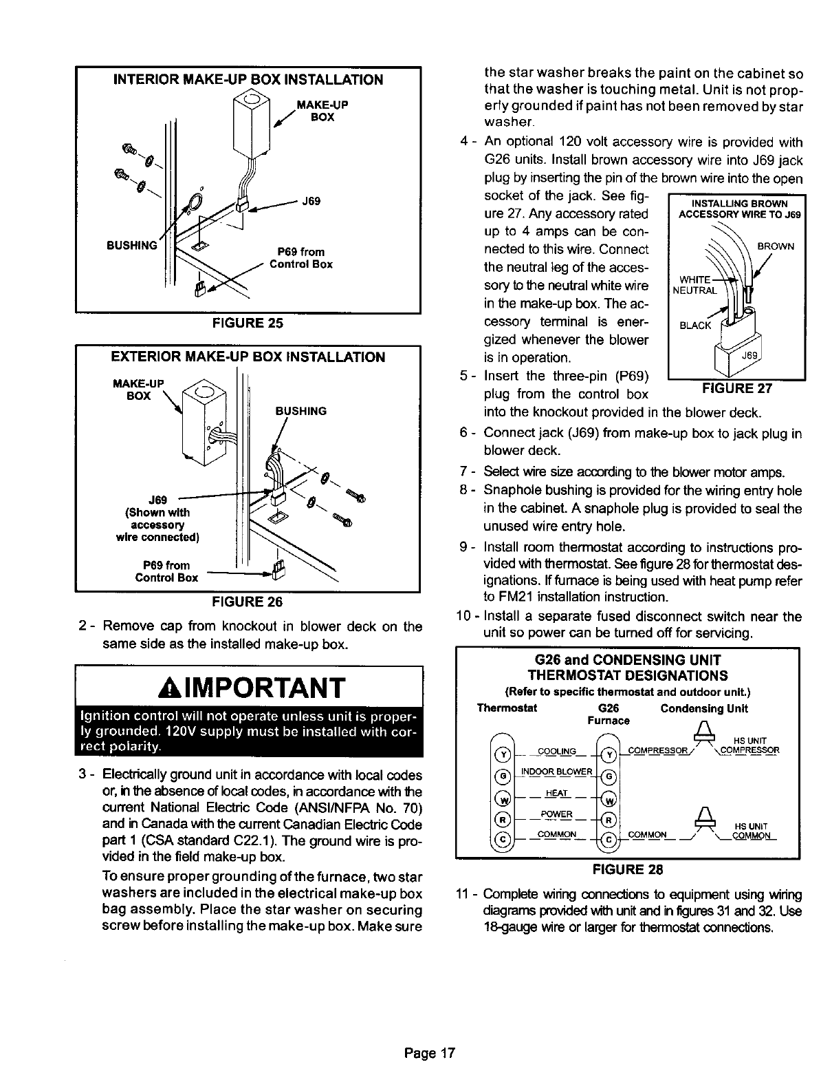
INTERIORMAKE-UPBOXINSTALLATION
BUSHING P69 from
Control Box
FIGURE 25
EXTERIOR MAKE-UP BOX INSTALLATION
MAKE-UP
BOX BUSHING
J69
(Shown wlth
accessory
wire connected)
P69 from
Control Box
FIGURE 26
2- Remove cap from knockout in blower deck on the
same side as the installed make-up box.
AIMPORTANT
3 - Electrically ground unit in accordance with local codes
or, inthe absence of local codes, inaccordance withthe
current National Electdc Code (ANSI/NFPA No. 70)
and inCanada withthe currentCanadian Electdc Code
part 1 (CSA standard C22.1). The ground wire is pro-
vided in the field make-up box.
To ensure proper grounding of the furnace, two star
washers are included in the electrical make-up box
bag assembly. Place the star washer on securing
screw before installing the make-up box. Make sure
4-
5-
_
7-
8-
_
10-
the star washer breaks the paint on the cabinet so
that the washer is touching metal. Unit is not prop-
erly grounded if paint has not been removed by star
washer.
An optional 120 volt accessory wire is provided with
G26 units. Install brown accessory wire into J69 jack
plug by inserting the pin of the brown wire into the open
socket of the jack. See fig- INSTALLINGBROWN
ure 27. Any accessory rated ACCESSORYWIRETOJ69
up to 4 amps can be con-
nected to this wire. Connect BROWN
the neutral leg of the acces-
sory to the neutral white wire NEUTRAL
in the make-up box. The ac-
cessory terminal is ener-
gized whenever the blower
is in operation.
Insert the three-pin (P69)
plug from the control box FIGURE 27
into the knockout provided in the blower deck.
Connect jack (J69) from make-up box to jack plug in
blower deck.
Select wire size accordingto the blower motoramps.
Snaphole bushing is providedfor the widng entry hole
in the cabinet. Asnaphole plug is provided to seal the
unused wire entry hole.
Install room thermostat according to instructionspro-
vided with thermostat. See figure 28 for thermostat des-
ignations. Iffurnace is being used withheat pump refer
to FM21 installation instruction.
Install a separate fused disconnect switch near the
unit so power can be turned off for servicing.
G26 and CONDENSING UNIT
THERMOSTAT DESIGNATIONS
(Refer to specific thermostat and outdoor unit.)
Thermostat G26 Condensing Unit
Furnace
_ _ HS UNIT
® coMP.Esso.
® ,NDOO,.LOWE,®1
@
®
@
@j
owE, ®j .SUNiT
COMMON @COMMON /_COMMON
FIGURE 28
11 - Complete widng connecfions to equipment using wiring
diagrams provided_unitand infigures31 and 32. Use
18-gauge wire or largerfor thermostat connections.
Page 17
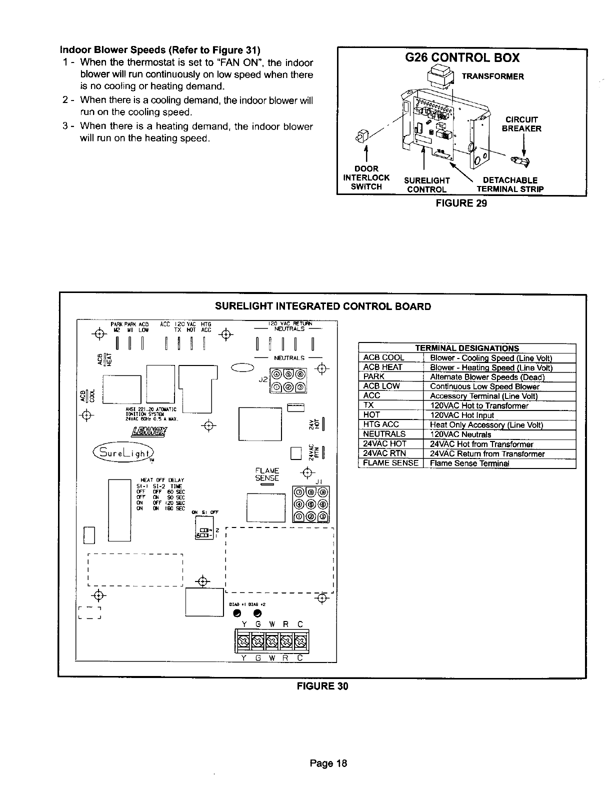
IndoorBlowerSpeeds(Referto Figure31)
1-When the thermostat is set to "FAN ON", the indoor
blower will run continuously on low speed when there
is no cooting or heating demand.
2-When there is a cooling demand, the indoor blowerwill
run on the cooling speed.
3-When there is a heating demand, the indoor blower
will run on the heating speed.
G26CONTROLBOX
TRANSFORMER
CIRCUIT
• BREAKER
DOOR _
INTERLOCK SURELIGH DETACHABLE
SWITCH CONTROL TERMINAL STRIP
FIGURE 29
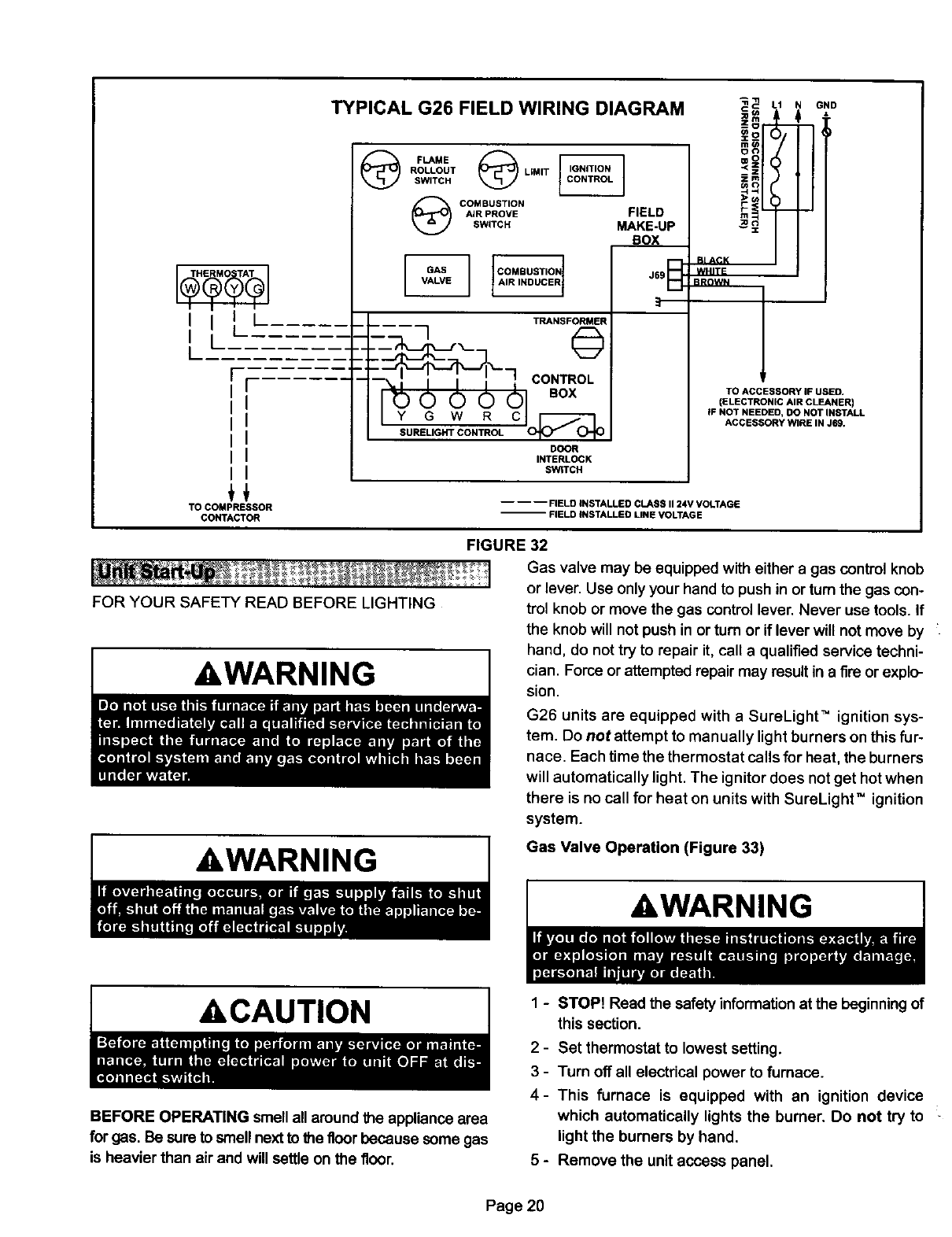
SURELIGHT INTEGRATED CONTROL BOARD
P_ PAF_ ACB
I_ MI LOW
IIH 111t
I6_ITION SYST(_
ANSI _ZI _Z0 ATG_IATIC
Z4VAC 60Hz 0_5 AMAX_ ÷
ACC 12OVAC HTG 12o VAC RETtJ_
-- NEUTRALS --
TX.o,,co÷ Ilnll
mMEUTRALS m
C>j2 _ ÷
FLAME
HEATOFFBELAY SENSE j
S!-I SI-2 TIME
0_F OFF 60 9EC
OFF ON 90 5EC
(_N OFF +20 SIEC
D-
I
r-- 1
I I I
I i I
÷
I
__ --_ L
F -- 1
___ ®®
Y G W R C
Y G W RC
ACS COOL
ACS HEAT
PARK
ACB LOW
ACC
TX
HOT
HTG ACC
NEUTRALS
24VAC HOT
24VAC RTN
FLAME SENSE
TERMINAL DESIGNATIONS
Blower - Cooling Speed (Line Volt)
Slower - Heating Speed (Line Volt)
Alternate Blower Speeds (Dead)
Continuous Low Speed Blower
Accessory Terminal (Line Volt)
120VAC Hot to Transformer
120VAC Hot Input
Heat Only Accessory (Line Volt)
120VAC Neutrals
24VAC Hot fTomTransformer
24VAC Return fTom Transformer
Flame Sense Terminal
FIGURE 30
Page 18

TYPICAL G26 WIRING DIAGRAM
I20v ACC
On
K43 EC_I
(IF US_}
N_
LI m
SI
ROOMTHERf_TAT
© 0 ®
SiS 510
_UB_STION AIR PRIMARY 6AS $47
LIMIT FL_ME R_J=0UT
SVITGH
CIOR__USTU_ON
MOTOR
JI56_ CIRCUIT
(J2) BI_J_I_
_TAT HEAT
.'_HTICIPAT I_4_l_TTIN65
BLOtER _PEEO CHART
IFACTOAy CONNECTED5PE]EDTAPS
_.-50 I..... I....
.... YELLOW
El B{.ACE .... Ig_qO_q
.... I'_I.LOI
_]_-IO0, I_1 IYI[U.IN I InA_lnl IBI_IE
HI • BLOCRRSPEE_ _TI_, LO
IELAf_X YI_J_q R_)
I_LACE BROTH PaIF YELLO_ R£D
lAdlING-
_LEC_IIC _ HAZARDCAN _U_ INJURy
0t fl_IIt,UN T _8_ _ IN A_clO_E
FIGURE 31
Page19
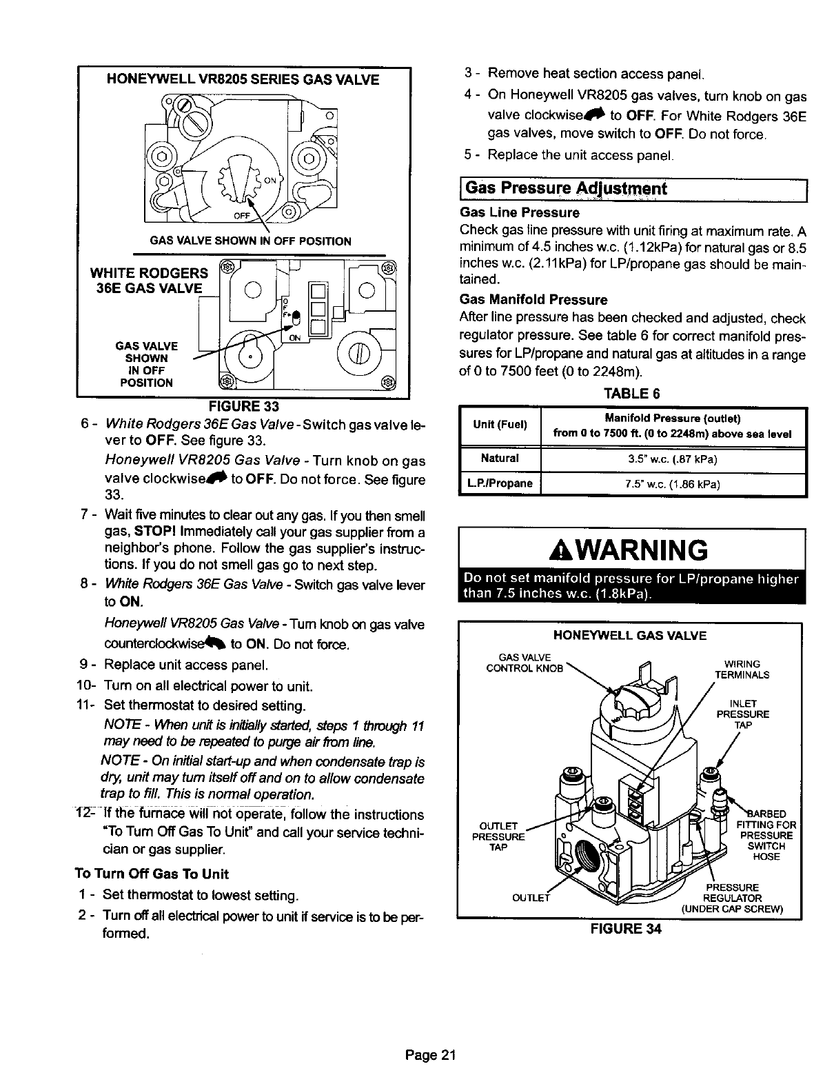
TYPICAL G26 FIELD WIRING DIAGRAM
I I , i
I
,II'
I
r
ir
i I
ii
ii
ii
ii
TO COMPRESSOR
CONTACTOR
FLAME @
ROLLOUT LIMIT
SWITCH
COMBUSTION
AIR PROVE FIELD
SWITCH MAKE-UP
BOX
v%,%
TRANSFORMER
7CONTROL
ooddl .ox
ILIGAON L DOOR
INTERLOCK
SWITCH
FOR YOUR SAFETY READ BEFORE LIGHTING
AWARNING
_L1 GND
==odi
°°l
--Z
znl
00(3
RI ACK
WHITE
BROWN
TO ACCESSORY IF USED.
(ELECTRONIC AIR CLEANER)
IF NOT NEEDED, DO NOT INSTALL
ACCESSORY WIRE IN J69.
-- -- -- FIELD INSTALLED CLASS II 24V VOLTAGE
-- FIELD iNSTALLED UNE VOLTAGE
FIGURE 32
Gas valve may be equipped with either agas control knob
or lever. Use only your hand to push in or turn the gas con-
trol knob or move the gas control lever. Never use tools. If
the knob will not push in or turn or if lever will not move by
hand, do not try to repair it, call a qualified service techni-
cian. Force or attempted repair may result in a fire or explo-
sion.
G26 units are equipped with a SureLighU" ignition sys-
tem. Do not attempt to manually light burners on this fur-
nace. Each time the thermostat cells for heat, the burners
will automatically light. The ignitor does not get hot when
there is no cell for heat on units with SureLight TM ignition
system.
Gas Valve Operation (Figure 33)
AWARNING
ACAUTION
BEFORE OPERATING smell all around the appliance area
for gas. Be sure to smell next to the floor because some gas
is heavier than air and will settle on the floor.
1- STOP! Read the safety informationat the beginningof
this section.
2 - Set thermostat to lowest setting.
3 - Turn off all electrical power to furnace.
4- This furnace is equipped with an ignition device
which automatically lights the burner. Do not try to
light the burners by hand.
5-Remove the unit access panel.
Page 20
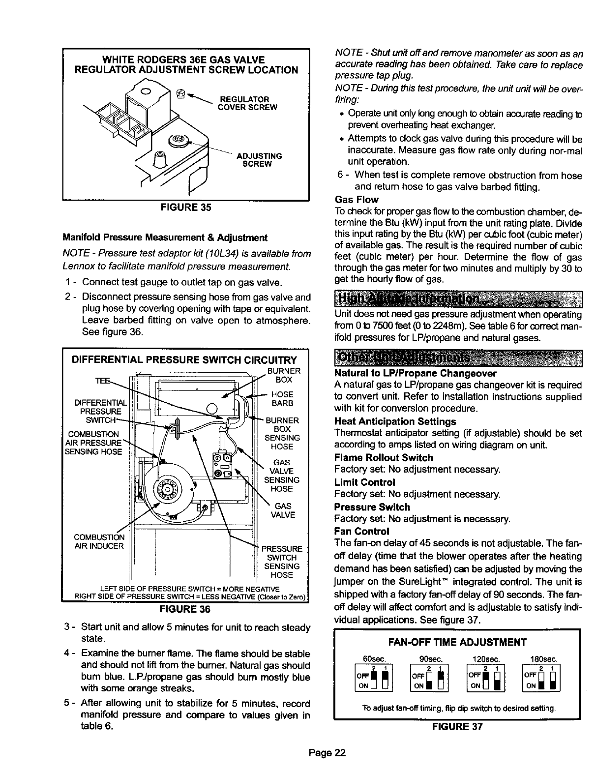
HONEYWELLVR8205SERIESGASVALVE
\
GAS VALVE SHOWN IN OFF POSITION
WHITE RODGERS
36E GAS VALVE
GAS VALVE _
SHOWN
iN OFF
POSITION
FIGURE 33
6 - Whffe Rodgers 36E Gas Valve -Switch gas valve le-
verto OFF. See figure 33.
Honeywell VR8205 Gas Valve - Turn knob on gas
valve clockwise_lt' to OFF. Do not force. See figure
33.
7 - Wait five minutes to clear out any gas. If you then smell
gas, STOP! Immediately call your gas supplier from a
neighbor's phone. Follow the gas supplier's instruc-
tions. If you do not smell gas go to next step.
8 - White Rodgers 36E Gas Valve - Switch gas valve lever
to ON.
Honeywell VR8205 Gas Valve -Tum knob on gas valve
counterctockwi_ to ON. Do not force.
9 - Replace unit access panel.
10- Turn on all electrical power to unit.
11- Set thermostat to desired setting.
NOTE -When unit is initiallystarted, _eps 1 through 11
may need to be repeated to purge air from line.
NOTE- On initial start-up and when condensate trap is
dry, unit may turn itseff off and on to allow condensate
trap to fill. This is normal operation.
12- If the furnace wii/not operate, follow the instructions
=ToTurn Off Gas To Unit" and call your service techni-
cian or gas supplier.
To Turn Off Gas To Unit
1 - Set thermostat to lowest setting.
2-Turn offall electricalpower to unit if service is to be per-
formed.
3 - Remove heat section access panel.
4 - On Honeywell VR8205 gas valves, turn knob on gas
valve clockwise4_ to OFF. For White Rodgers 36E
gas valves, move switch to OFF Do not force.
5 - Replace the unit access panel.
JGas Pressure Adjustment I
Gas Line Pressure
Check gas fine pressure with unit firing at maximum rate. A
minimum of 4.5 inches w.c. (1.12kPa) for natural gas or 8.5
inches w.c. (2.11kPa) for LP/propane gas should be main-
tained.
Gas Manifold Pressure
After line pressure has been checked and adjusted, check
regulator pressure. See table 6 for correct manifold pres-
sures for LP/propane and natural gas at altitudes in a range
of 0 to 7500 feet (0 to 2248m).
TABLE 6
Unit (Fuel) Manifold Pressure (outlet)
from 0 to 7500 ft. (0 to 2248nl) above sea level
Natural 3.5" w.c. (.87 kPa)
L.P.IPropane 7.5" w.c. (1.86 kPa)
&WARNING
GAS VALVE
CONTROL KNOB
OUTLET
PRESSURE
TAP c
ou
FIGURE 34
HONEYWELL GAS VALVE
WIRING
TERMINALS
INLET
PRESSURE
TAP
/
_BARBED
FITnNG FOR
PRESSURE
SWITCH
HOSE
PRESSURE
REGULATOR
(UNDER CAP SCREW)
Page 21
WHITE RODGERS 36E GAS VALVE
REGULATOR ADJUSTMENT SCREW LOCATION
_'_ REGULATOR
COVER SCREW
ADJUSTING
SCREW
FIGURE 35
Manifold Pressure Measurement & Adjustment
NOTE -Pressure test adaptor kit (10L34) is available from
Lennox to facilitate manifold pressure measurement.
1 - Connect test gauge to outlet tap on gas valve.
2 - Disconnect pressure sensing hose from gas valve and
plug hose by covering opening with tape or equivalent.
Leave barbed fitting on valve open to atmosphere.
See figure 36.
DIFFERENTIAL PRESSURE SWITCH CIRCUITRY
BURNER
BOX
BARB
PRESSURE
BOX
COMBUSTION SENSING
AIR PRESSURE _HOSE
SENSING HOSE
GAS
VALVE
SENSING
HOSE
GAS
VALVE
AIRINDUCER •PRESSURE
SWITCH
SENSING
HOSE
LEFT SIDE OF PRESSURE SWITCH = MORE NEGATIVE
RIGHT SIDE OF PRESSURE SWITCH = LESS NEGATIVE (Closer to Zero)
FIGURE 36
3 - Start unit and allow 5 minutes for unit to reach steady
state.
4-Examine the burner flame. The flame should be stable
and should not liftfrom the burner. Natural gas should
bum blue. L.P./propane gas should bum mostly blue
with some orange streaks.
5 - After allowing unit to stabilize for 5 minutes, record
manifold pressure and compare to values given in
table 6.
NOTE -Shut unit off and remove manometer as soon as an
accurate reading has been obtained. Take care to replace
pressure tap plug.
NOTE -During this test procedure, the unit unit will be over-
firing:
•Operate unit only long enough to obtain accurate reading to
prevent oveilleaUng heat exchanger.
• Attempts to clock gas valve during this procedure will be
inaccurate. Measure gas flow rate only during nor-mal
unit operation.
6 - When test is complete remove obstruction from hose
and return hose to gas valve barbed fitting.
Gas Flow
To checkfor propergas flow tothe combustionchamber, de-
termine the Btu (kW) inputfrom the unit rating plate. Divide
this inputratingby the Btu(kW) per cubic foot (cubic meter)
of available gas. The result is the required number of cubic
feet (cubic meter) per hour. Determine the flow of gas
through the gas meter for two minutes and multiplyby 30 to
get the houdyflow of gas.
Unit does notneed gas pressure adjustmentwhen operating
from 0 to 7500 feet (0 to 2248m). See table 6 for correctman-
ifoldpressuresfor LP/propane and natural gases.
Natural to LP/Propane Changeover
A natural gas to LP/propane gas changeover kit is required
to convert unit. Refer to installation instructions supplied
with kit for conversion procedure.
Heat Anticipation Settings
Thermostat anticipator setting (if adjustable) should be set
accordingto amps listed on wiring diagram on unit.
Flame Rollout Switch
Factory set: No adjustment necessary.
Limit Control
Factory set: No adjustment necessary.
Pressure Switch
Factory set: No adjustment is necessary.
Fan Control
The fan-on delay of 45 seconds is not adjustable. The fan-
off delay (time that the blower operates after the heating
demand has been satisfied) can be adjusted by moving the
jumper on the SureLight TM integrated control. The unit is
shipped with a factoryfan-off delay of 90 seconds. The fan-
off delay will affect comfort and is adjustable to satisfy indi-
vidual applications. See figure 37.
FAN-OFF TIME ADJUSTMENT
60sec, 90sec. 120sec. 180sec.
To adjust fan-off timing, flip dip switch to desired setting.
FIGURE 37
Page 22
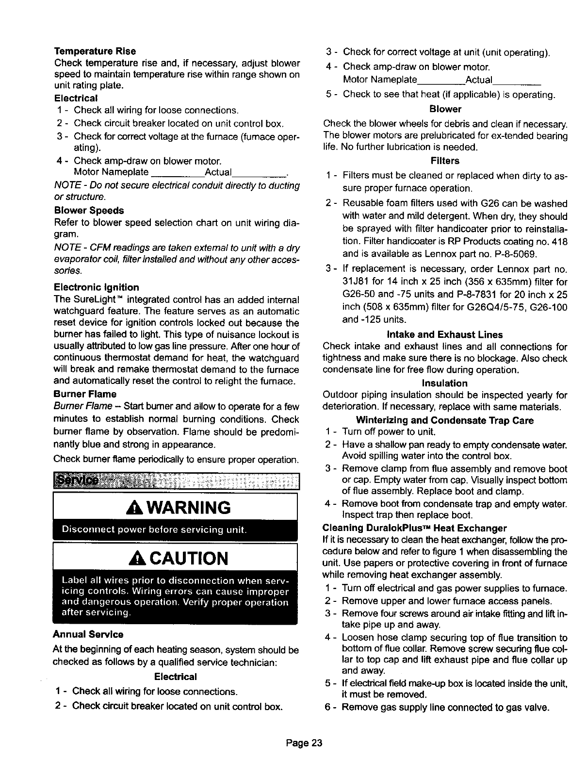
TemperatureRise
Check temperature rise and, if necessary, adjust blower
speed to maintain temperature risewithin range shown on
unit rating plate.
Electrical
1 - Check all wiring for loose connections.
2 - Check circuit breaker located on unit control box.
3 - Check for correct voltage at the furnace (furnace oper-
ating).
4 - Check amp-draw on blower motor.
Motor Nameplate Actual
NOTE -Do not secure electrical conduit directly to ducting
or structure.
Blower Speeds
Refer to blower speed selection chart on unit wiring dia-
gram.
NOTE -CFM readings are taken external to unit with a dry
evaporator coil, filter installed and without any other acces-
sories.
Electronic Ignition
The SureLight" integrated control has an added internal
watchguard feature. The feature serves as an automatic
reset device for ignition controls locked out because the
burner has failed to light. This type of nuisance lockout is
usually attributedto low gas line pressure. After one hourof
continuous thermostat demand for heat, the watchguard
will break and remake thermostat demand to the furnace
and automatically reset the control to relight the furnace.
Burner Flame
Burner Flame - Start burner and allow to operate for afew
minutes to establish normal burning conditions. Check
burner flame by observation. Flame should be predomi-
nantly blue and strong in appearance.
Check burner flame periodically to ensure proper operation.
&WARNING
&CAUTION
Annual Service
At the beginning of each heating season, system should be
checked as follows by a qualified service technician:
Electrical
1 - Check all wiring for loose connections.
2-Check circuit breaker located on unit control box.
3 - Check for correct voltage at unit (unit operating).
4 - Check amp-draw on blower motor.
Motor Nameplate Actual
5 - Check to see that heat (if applicable) is operating.
Blower
C'heck the blower wheels for debris and clean if necessary.
The blower motors are prelubricated for ex-tended bearing
life. No further lubrication is needed.
Filters
1 - Filters must be cleaned or replaced when dirty to as-
sure proper furnace operation.
2 - Reusable foam filters used with G26 can be washed
with water and mild detergent. When dry, they should
be sprayed with filter handicoater prior to reinstalla-
tion. Filter handicoater is RP Products coating no. 418
and is available as Lennox part no. P-8-5069.
3 - If replacement is necessary, order Lennox part no.
31J81 for 14 inch x 25 inch (356 x 635mm) filter for
G26-50 and -75 units and P-8-7831 for 20 inch x 25
inch (508 x 635mm) filter for G26Q415-75, G26-100
and -125 units.
Intake and Exhaust Lines
Check intake and exhaust lines and all connections for
tightness and make sure there is no blockage. Also check
condensate line for free flow during operation.
Insulation
Outdoor piping insulation should be inspected yearly for
deterioration. If necessary, replace with same materials.
Winterizing and Condensate Trap Care
1 - Turn off power to unit.
2 - Have a shallow pan ready to empty condensate water.
Avoid spilling water into the control box.
3 - Remove clamp from flue assembly and remove boot
or cap. Empty water from cap. Visually inspect bottom
of flue assembly. Replace boot and clamp.
4 - Remove boot from condensate trap and empty water.
Inspect trap then replace boot.
Cleaning DuralokPlus TM Heat Exchanger
If it is necessary to clean the heat exchanger, follow the pro-
cedure below and refer to figure 1 when disassembling the
unit. Use papers or protective covering in front of furnace
while removing heat exchanger assembly.
1 - Turn off electrical and gas power supplies to furnace.
2 - Remove upper and lower furnace access panels.
3- Remove four screws around air intake fittingand lift in-
take pipe up and away.
4 - Loosen hose clamp securing top of flue transition to
bottom of flue collar. Remove screw securing flue col-
lar to top cap and lift exhaust pipe and flue collar up
and away.
5 - If electrical field make-up box is located inside the unit,
it must be removed.
6 - Remove gas supply line connected to gas valve.
Page 23
7-Mark all gas valve wires and disconnect them from
valve. Mark and remove wires from flame roll-out
switch.
8 - Remove top cap of unit.
9- Remove sensor wire from SureLight" control. Dis-
connect 2-pin plug from the ignitor.
10- Mark and disconnect pressure switch tubing from both
sides of the pressure switch.
11 - Loosen two screws holding gas manifold support at
vestibule panel.
12 - Remove four burner box screws at the vestibule panel
and remove burner box and gas valve/manifold as-
sembly with bracket.
13- Drain condensate trap. Disconnect condensate line
from the outside of unit. Remove condensate line from
condensate trap by turning the adapter fitting counter-
clockwise. The fitting has standard right-hand
threads.
14 - Disconnect the drain hose from the flue transition to
the elbow on the cold header (collector) box trap.
15 - Disconnect the 2-pin plug from the combustion air in-
ducer at the blower deck. Remove four screws from
combustion air inducer and remove flue transition and
inducer assembly from cabinet. Take care not to lose
the combustion air orifice.
16 - Disconnect 9-pin plug from the blower compartment at
the blower deck.
17 - Remove 9-pin plug above the blower deck.
18 - Remove the limit switch and the pressure switch from
the vestibule panel.
19 - Remove two screws from the front cabinet flange at
the blower deck. Remove front screws from cabinet at
blower deck on left and dght sides. Cabinet sides must
be slightly spread to clear heat exchanger passage.
20- Remove screws along vestibule sides and bottom
which secure vestibule panel and heat exchanger as-
sembly to cabinet. Remove heat exchanger.
21- Back wash heat exchanger with soapy water solution
or steam. If steam is used it must be below 275°F
(135°C).
22 - Thoroughly rinse and drain the heat exchanger. Soap
solution can be corrosive so take care that entire as-
sembly is completely rinsed.
23 - Re-install heat exchanger into cabinet making sure
that the clamshells of the heat exchanger assembly
are resting inthe notches of the support located at the
rear of the cabinet. This can be viewed by removing
the indoor blower and examining through the blower
opening.
24 - Re-secure the supporting screws along the vestibule
sides and bottom to the cabinet.
25 -Re-install cabinet screws on sides and front flange at
blower deck.
26 - Re-install the limit switch and pressure switch on the
vestibule panel.
27 - Re-install 9-pin plug to blower deck and connect it to
the 9-pin plug from below the blower deck.
28 - Re-install the combustion air inducer. Check the plas-
tic orifice in the inducer inlet to make sure it has not
fallen out. See figure 1. Reconnect the 2-pin plug to
the wire harness. Re-install the flue transition in the
cabinet and re-attach the drain tube. Route the drain
tube below the combustion air inducer housing and to
the elbow on the cold header (collector) box trap. See
figure 36.
29 - Re-install condensate line with adapter to condensate
trap. Use fresh Teflon tape to ensure a leak-free joint.
Re-connect to condensate line outside of the unit.
30 - Re-install the burner box. Tighten the screws holding
the support bracket. It is important that the glass fiber
gasket not be damaged so it will provide a continuous
seal between the burner box and the vestibule panel
31 - With the pressure switch mechanism oriented on the
right, reconnect pressure switch tubing by connecting
the tubing from the burner box to the barbed fitting on
the bottom. Connect the tubing from the combustion
air inducer to the barbed fitting on the top. See figure
36.
32 - Reconnect the sensor and ignitorwires.
33 -Re-install top cap to unit.
34 - Re-instaU electrical connections to gas valve. Orange
wire to M1 and yellow wire to C2. Reconnect wires to
flame roll-out switch.
NOTE -Unit is polarity-sensitive. 120V supply wiring
must be installed correctly.
35 - Reconnect main gas line to gas valve.
36 - Re-install field make-up box if removed.
37 - Re-install exhaust pipe/flue collar and secure flue col-
lar to the unit top cap using existing screw. Insert the
bottom of the flue collar into the top of the flue transi-
tion and tighten hose clamp.
38 - Re-install intake pipe fitting to burner box with screws.
39 - Replace both upper and lower access panels.
40 - Refer to instruction on verifying gas and electrical con-
nections when re-establishing supply.
41 - Following lighting instructions from installation manu-
al, light and run unit for 5 minutes to ensure heat ex-
changer is clean, dry and operating safely.
Cleaning the Burner Assembly
1-Turn off electrical and gas power supplies to fumaca.
Remove upper and lower furnace access panels.
2-Disconnect the gas supply line to gas valve. Depend-
ing on gas plumbing installation,the gas manifold may
move aside enough that breaking the union may not
be necessary.
3 - Remove five screws from edges of burner box cover.
G26-50 units have only four screws.
4 - Loosen two screws on bottom of burner box front. The
cover is key holed at these screw point so screws do
not need to be removed. Pull off cover and set aside.
6 - Mark all gas valve wires and disconnect them from
valve.
7 - Mark and disconnect sensor wires from the burner box
at the ignition control. Disconnect 2-pin plug from the
ignitor at the burner box,
Page 24
8-Loosen two screws at the gas manifold support brack-
et.
9 - Pull on the left side of the gas manifold and follow with
tension to the right side. The manifold support bracket
will be free of the mounting screws on the vestibule
panel. Set the gas manifold/gas valve assembly aside.
Take care not to damage foam gaskets on each end of
the gas manifold.
10 -Using a 1/4 inch nut driver, remove the burner mount-
ing screws from underneath the burners.
11 - While supporting ignitor and sensor lines at the grom-
met, grasp burners and simultaneously pull burners
and grommet out of the burner box.
12 - Remove ignitor and sensor bracket assemblies from
burners using a 1/4 inch nut driver to remove two
screws from each bracket.
13 - Clean burner by running a vacuum with a soft brush at-
tachment over face of burners. Visually inspect inside of
burners and crossovers for any blockage caused by for-
eign matter. Remove any blockage.
14 - Re-install ignitor and sensor bracket assemblies on
burners.
NO TE -Ignitor must be installed on the opposite side of
the burner from the metal button protrusions. Screws
which attached the ignitor bracket must be installed
from the same side as the ignitor and through the brack-
et to engage in the smaller holes located in the burner.
The correct burner orientation is with metal button pro-
trusions always pointing up.
15 - Replace burner ignitor assembly back into burner box
so that grommet groove fits back into sheet metal
notch and makes a good seal. The bumers sit on top of
the burner box flanges. Make certain that the screws
from the underneath the box pass through the larger
holes in the flange and engage in the smaller holes in
the burner. Re-install the two screws.
16 - Re-install the gas manifold/gas valve assembly by first
inserting the right hand side of the gas manifold into
the burner box. Swing left side of manifold into box
while engaging support bracket to vestibule panel
screws. Check that foam gaskets are providing a seal
around each end of the gas manifold. All gas orifices
should be engaged. If at this point the burners were
mounted in the wrong holes, this needs to be cor-
rected. The saddle brackets on the gas manifold
should be flush with the front surfaces on the burner
box sides.
17 - Inspect the dual layered metal pieces at the front lip of
the cover. These pieces must sandwich around the
metal. Re-install burner box cover.
18 - Re-install the screws to secure the burner box cover.
Make sure screws are tight to ensure a leak tight bum-
er box. Tighten the two screws underneath the box.
Again, inspect the grommet to ensure a tight seal.
19 - Tighten the two screws holding the manifold bracket to
the vestibule panel.
20 - Re-install the electrical connections to the gas valve.
Orange wire to M1 and yellow wire to C2.
21 - Re-install the 2-pin ignitor plug at the burner box. Re-
install sensor line to ignition control spade connector.
22 - Reconnect gas line to gas valve.
23 - Replace lower access panel.
24 - Following lighting instructions and gas line connection
test procedures from installation manual.
25 - Replace upper access panel.
Page 25
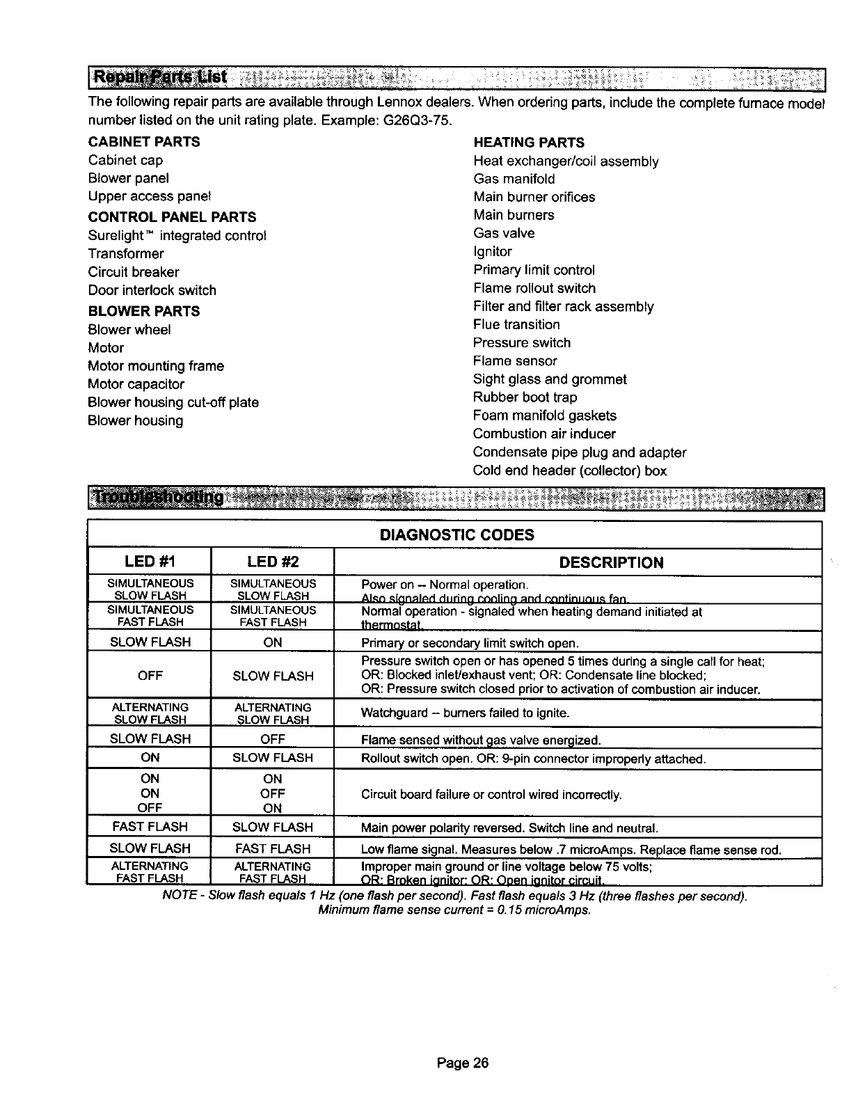
The following repair parts are available through Lennox dealers.
number listed on the unit rating plate. Example: G26Q3-75.
CABINET PARTS
Cabinet cap
Blower panel
Upper access panel
CONTROL PANEL PARTS
Surelight" integrated control
Transformer
Circuit breaker
Door interlock switch
BLOWER PARTS
Blower wheel
Motor
Motor mounting frame
Motor capacitor
Blower housing cut-off plate
Blower housing
When ordering parts, include the complete fumace model
HEATING PARTS
Heat exchanger/coil assembly
Gas manifold
Main burner orifices
Main burners
Gas valve
Ignitor
Primary limit control
Flame rollout switch
Filter and filter rack assembly
Flue transition
Pressure switch
Flame sensor
Sight glass and grommet
Rubber boot trap
Foam manifold gaskets
Combustion air inducer
Condensate pipe plug and adapter
Cold end header (collector) box
DIAGNOSTIC CODES
LED #1
SIMULTANEOUS
SLOW FLASH
SIMULTANEOUS
FAST FLASH
SLOW FLASH
OFF
ALTERNATING
SLOW FLASH
SLOW FLASH
ON
ON
ON
OFF
FAST FLASH
SLOW FLASH
ALTERNATING
FAST FLASH
LED #2
SIMULTANEOUS
SLOW FLASH
SIMULTANEOUS
FAST FLASH
ON
SLOW FLASH
ALTERNATING
SLOW FLASH
OFF
SLOW FLASH
ON
OFF
ON
SLOW FLASH
FAST FLASH
ALTERNATING
FASTFLASH
DESCRIPTION
Power on - Normal operation.
Alan _inn_l_d dHrinn t_nnlinn _nd r_nfin=JnH_ fan
Normal operation - signaled when heating demand initiated at
thermostat
Primary or secondary limit switch open.
Pressure switch open or has opened 5 times during a single call for heat;
OR: Blocked inlet/exhaust vent; OR: Condensate line blocked;
OR: Pressure switch closed prior to activation of combustion air inducer.
Watchguard -burners failed to ignite.
Flame sensed without _las valve energized.
Rollout switch open. OR: 9-pin connector improperly attached.
Circuit board failure or control wired incorrectly.
Main power polarity reversed. Switch line and neutral.
Low flame signal. Measures below .7 microAmps. Replace flame sense rod.
Improper main ground or line voltage below 75 volts;
OR: Broken ieniter: OR: Oeen ieniter circuit.
NOTE -Slow flash equals 1Hz :one flash per second). Fast flash equals 3 Hz (three flashes per second).
Minimum flame sense current =O.15 mieroAmps.
Page 26
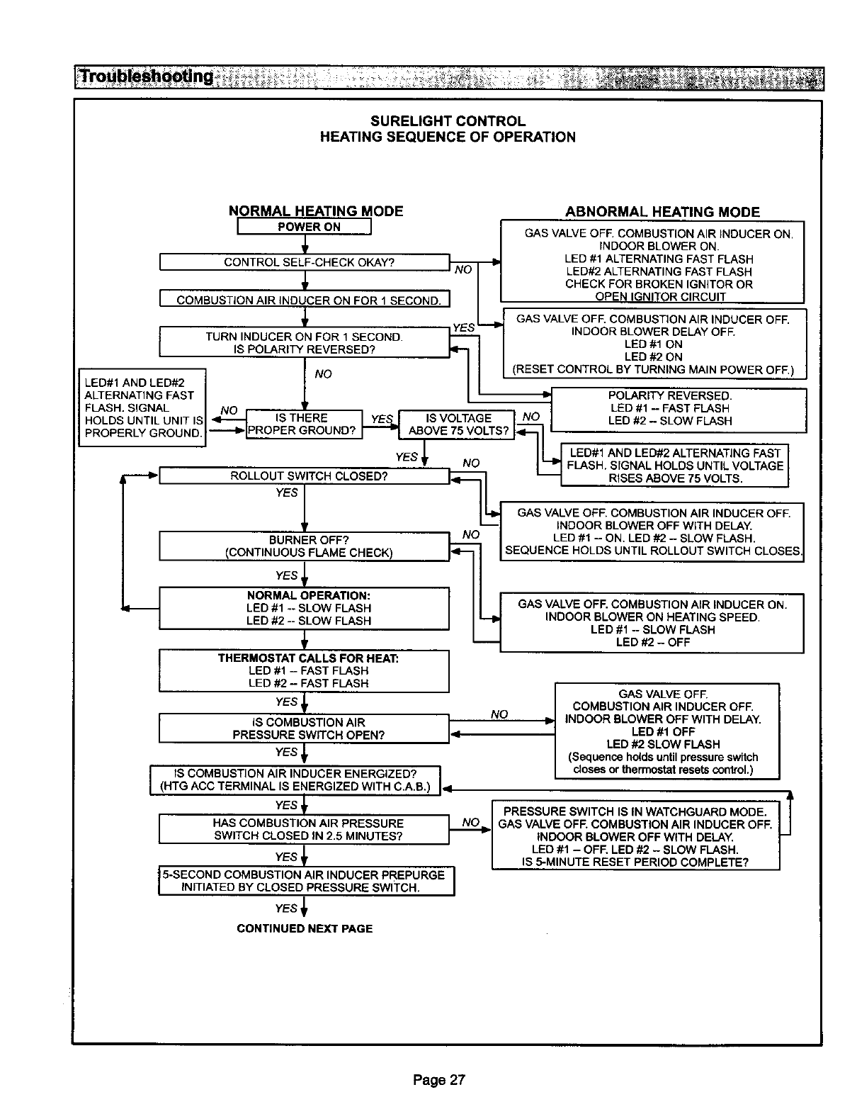
SURELIGHTCONTROL
HEATINGSEQUENCEOFOPEPu_,TION
NORMALHEATINGMODE
I POWERONI !
t
ICONTROL SELF-CHECK OKAY? NI-NI-NI-NI-NI-NI-NoO
ICOMBUSTION AIR INDUCER ON FOR 1 SECOND. I
ABNORMAL HEATING MODE
GAS VALVE OFE COMBUSTION AIR INDUCER ON.
INDOOR BLOWER ON.
LED #1 ALTERNATING FAST FLASH
LED#2 ALTERNATING FAST FLASH
CHECK FOR BROKEN IGNITOR OR
OPEN IGNITOR CIRCUIT
L GAS VALVE OFE COMBUSTION AIR INDUCER OFF.
[
TURN INDUCER ON FOR, SECOND. _ -_1 INDOOR B_EODWERDELAY OFF.
I ,sPOLAR,TYREVERSED? / LEDON
- , I.o I [ (RESET CONTROL BY TURNING MAIN POWER OFF.)
LED#1 AND LED#2 /
ALTERNATINGFASTI _ / _ POLARITYREVERSED
FLASH. SIGNAL NO / LED #1 - FAST FLASH
HOLDSUNTILUNITISI_ ISTHERE IYES.J ISVOLTAGEI N° I LED#2- SLOWFLASH
PROPERLY GROUND.I _ PROPER GROUND? ABOVE 75 VOLTS? I_------"l I
gYES III I LED#1 AND LED#2 ALTERNATING FAST
•NO I_ FLASH. SIGNAL HOLDS UNTIL VOLTAGE
---_1 ROLLOUTSWITCHCLOSED? _ _ RISESAEOVE75VOLTS. I
wsI II
II_ GAS VALVE OFF. COMBUSTION AIR INDUCER OFF.
I_ _1 INDOOR BLOWER OFF WITH DELAY.
BURNER OFF? L- I LED #1 - ON. LED #2 - SLOW FLASH.
(CONTINUOUS FLAME CHECK) I_L ROLLOUT SWITCH CLOSES
YES _
LED #1 -- SLOW FLASH GAS VALVE OFF. COMBUSTION AIR INDUCER ON.
LED #2 -- SLOW FLASH INDOOR BLOWER ON HEATING SPEED.
LED #1 - SLOW FLASH
LED #2 - OFF
ITHERMOSTAT CALLS FOR HEAT:
LED #1 - FAST FLASH
LED #2 -FAST FLASH I
GAS VALVE OFF./
YES _,: COMBUSTION AIR INDUCER OFF. I
I IS COMBUSTION AIR ,NO _INDOOR BLOWER OFF WITH DELAY.
IPRESSURE SWITCH OPEN? I" LED #1 OFF I
/LED #2 SLOW FLASH
YES (Sequence holds until pressure switch
I IS COMBUSTION AIR INDUCER ENERGIZED? I closes or thermostat resets control.)
I(HTG ACC TERMINAL IS ENERGIZED WITH C.A.B.) Iq
YEsYEST_ _ PRESSURE SWITCH IS IN WATCHGUARD MODE.
I HAS COMBUSTION AIR PRESSURE GAS VALVE OFF. COMBUSTION AIR INDUCER OFF.
SWITCH CLOSED IN 2.5 MINUTES? INDOOR BLOWER OFF WITH DELAY.
/ LED #1 - OFF. LED #2 - SLOW FLASH.
IS 5-MINUTE RESET PERIOD COMPLETE?
5-SECOND COMBUSTION AIR INDUCER PREPURGE I
INITIATED BY CLOSED PRESSURE swITCH. I
YES _
CONTINUED NEXT PAGE
Page 27
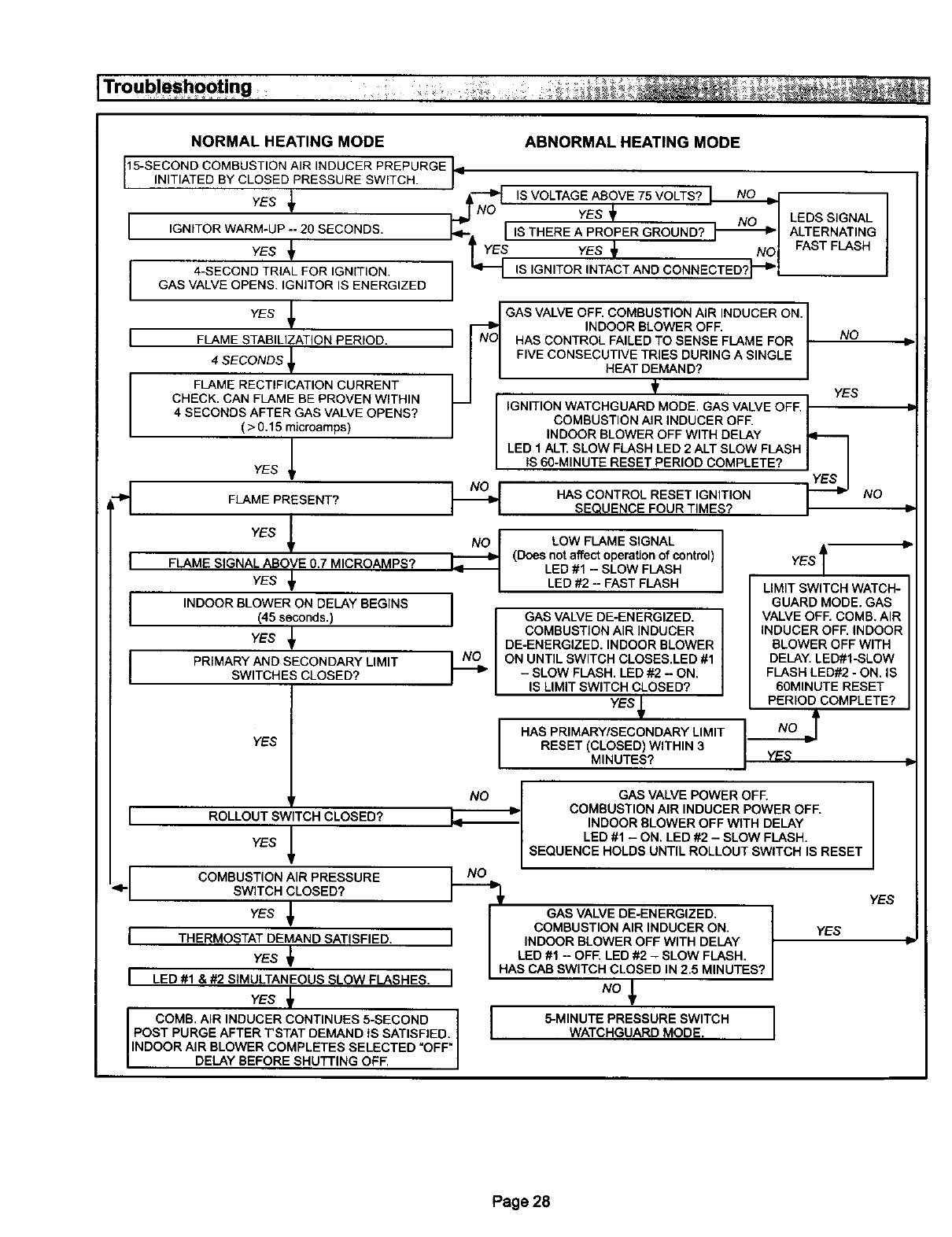
[Troub!eshoot!ng
NORMAL HEATING MODE
15-SECOND COMBUSTION AIR INDUCER PREPURGE il
[NT ATED BY CLOSED PRESSURE SW TCH. j
I
ABNORMAL HEATING MODE
YES JN'_O IS VOLTAGE ABOVE 75 VOLTS?
YES -1 NO _I
_t_ IS THERE A PROPER GROUND? I--_1
YEs Nol
IS IGNITOR INTACT AND CONNECTED?_I
IGNITOR WARM-UP -- 20 SECONDS.
yes
4-SECOND TRIAL FOR IGNITION.
GAS VALVE OPENS. IGNITOR IS ENERGIZED
YES _
FLAME STABILIZATION PERIOD.
4SECONDS J[
FLAME RECTIFICATION CURRENT
CHECK, CAN FLAME BE PROVEN WITHIN
4SECONDS AFTER GAS VALVE OPENS?
( > 0.15 mJcroamps)
YES _
FLAME PRESENT?
YES l
FLAME SIGNAL ABOVE 0.7 MICROAMPS?
YES _
INDOOR BLOWER ON DELAY BEGINS
(45 seconds, )
YES _
PRIMARY AND SECONDARY LIMIT
SWITCHES CLOSED?
YES
LEDS SIGNAL
ALTERNATING
FAST FLASH
/ GAS VALVE OFF. COMBUSTION AIR INDUCER ON. I
NDOOR BLOWER OFF I
I I N°I HAS CONTROL FAILED TO SENSE FLAME FOR INO
I I FIVE CONSECUTIVE TRIES DURING A SINGLE I
I I HEAT DEMAND? I
]1 ' t YEs
_1 IIGNITION WATCHGUARD MODE, GAS VALVE OFF. I" --
I I COMBUSTION AIR INDUCER OFF. |
IIINDOOR BLOWER OFF WITH DELAY 14-----i
LED 1ALT. SLOW FLASH LED 2ALT SLOW FLASH II
IIS 60-MINUTE RESET PERIOD COMPLETE? I I
YES
]___ HAS CONTROL RESET IGNITION _-_-_JNO
II SEQUENCE FOUR TIMES? I"
(Does nLoOta%FctLAoMEraS_oGNoAfLcont rol)
LED #1 - SLOW FLASH
I LED #2 - FAST FLASH
GAS VALVE DE-ENERGIZED.
COMBUSTION AIR INDUCER
DE-ENERGIZED. INDOOR BLOWER
ON UNTIL SWITCH CLOSES,LED #1
-SLOW FLASH. LED #2 - ON.
IS LIMIT SWITCH CLOSED?
YES f
lHAS PRIMARY/SECONDARY LIMIT
RESET (CLOSED) WITHIN 3
MINUTES?
YES l"
LIMIT SWITCH WATCH-
GUARD MODE. GAS
VALVE OFF. COMB. AIR
INDUCER OFF. INDOOR
BLOWER OFF WITH
DELAY. LED#I-SLOW
FLASH LED#2 - ON. IS
60MINUTE RESET
PERIOD COMPLETE?
YES
I
1
ROLLOUT SWITCH CLOSED?
YES
ICOMBUSTION AIR PRESSURE<- SWITCH CLOSED?
YES _1
[THERMOSTAT DEMAND SATISFIED.
YES
[LED #1  SIMULTANEOUS SLOW FLASHES.
YES
COMB. AIR INDUCER CONTINUES 5-SECOND I
POST PURGE AFTER TSTAT DEMAND tS SATISFIED. I
INDOOR AIR BLOWER COMPLETES SELECTED OFF
DELAY BEFORE SHUTTING OFF.
E_ GAS VALVE POWER OFF.
COMBUSTION AIR INDUCER POWER OFF.
INDOOR BLOWER OFF WITH DELAY
LED #1 - ON. LED #2 - SLOW FLASH.
SEQUENCE HOLDS UNTIL ROLLOUT SWITCH IS RESET
YES
GAS VALVE DE-ENERGIZED.
YES
I COMBUSTION AIR INDUCER ON.
1INDOOR BLOWER OFF WITH DELAY
LED #1 - OFF. LED #2 - SLOW FLASH,
1HAS CAB SWITCH CLOSED IN 2.5 MINUTES?
INo
5-MINUTE PRESSURE SWITCH
WATCHGUARD MODE. 1
IlL:
Page 28
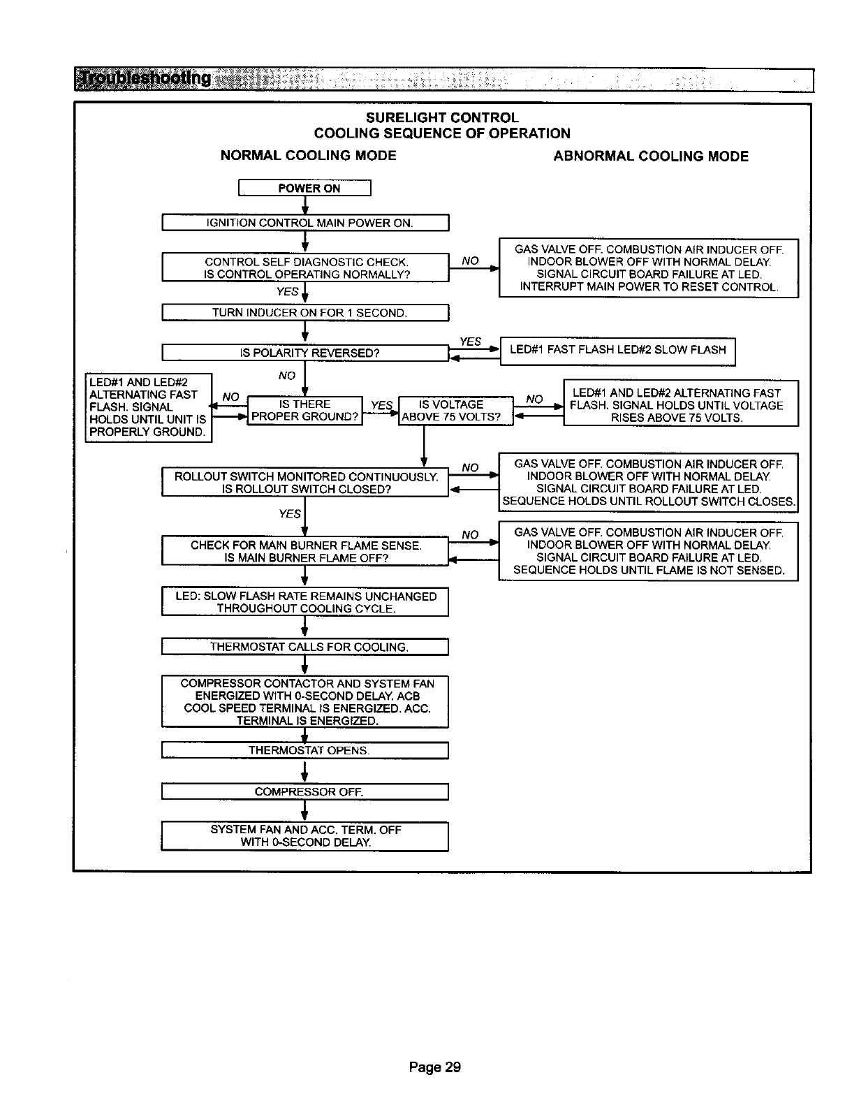
SURELIGHTCONTROL
COOLINGSEQUENCEOFOPERATION
NORMALCOOLINGMODE ABNORMALCOOLINGMODE
I
I
[
r
I POWER ON I
IGNITION CONTROL MAIN POWER ON. I
CONTROL SELF DIAGNOSTIC CHECK.
IS CONTROL OPERATING NORMALLY?
YES JI
TURN INDUCER ON FOR 1SECOND. I
YES r
IS POLARITY REVERSED? L-_=-z--_l
/
LED#1 AND LED#2 1NO J,
ALTERNATING FAST I NO ,IS THERE•' '
FLASH, SIGNAL _IYE&I IS VOLTAGE
HOLDS UNTIL UNIT IS _ PROPER GROUND? I_"WlABOVE 75 VOLTS?
PROPERLY GROUND. J
GAS VALVE OFF. COMBUSTION AIR INDUCER OFE
INDOOR BLOWER OFF WITH NORMAL DELAY.
SIGNAL CIRCUIT BOARD FAILURE AT LED.
INTERRUPT MAIN POWER TO RESET CONTROL•
LED#1 FAST FLASH LED#2 SLOW FLASH ]
NILED#1 AND LED#2 ALTERNATING FAST
I_O-_ FLASH. SIGNAL HOLDS UNTIL VOLTAGE
I<_1 RISES ABOVE 75 VOLTS•
I
I
I
I
I
I
ROLLOUT SWITCH MONITORED CONTINUOUSLY.
IS ROLLOUT SWITCH CLOSED?
YES_
CHECK FOR MAIN BURNER FLAME SENSE.
IS MAIN BURNER FLAME OFF?
LED: SLOW FLASH RATE REMAINS UNCHANGED
THROUGHOUT COOLING CYCLE.
THERMOSTAT CALLS FOR COOLING,
€
COMPRESSOR CONTACTOR AND SYSTEM FAN
ENERGIZED WiTH 0-SECOND DELAY, ACB
COOL SPEED TERMINAL IS ENERGIZED. ACC,
TERMINAL IS ENERGfZED.
€
THERMOSTAT OPENS•
COMPRESSOR OFE
€
SYSTEM FAN AND ACC. TERM. OFF
WITH 0_ECOND DELAY,
GAS VALVE OFF. COMBUSTION AIR INDUCER OFF.
INDOOR BLOWER OFF WITH NORMAL DELAY.
SIGNAL CIRCUIT BOARD FAILURE AT LED,
SEQUENCE HOLDS UNTIL ROLLOUT SWITCH CLOSES
GAS VALVE OFF. COMBUSTION AIR INDUCER OFE
INDOOR BLOWER OFF WITH NORMAL DELAY.
SIGNAL CIRCUIT BOARD FAILURE AT LED.
SEQUENCE HOLDS UNTIL FLAME IS NOT SENSED.
Page 29
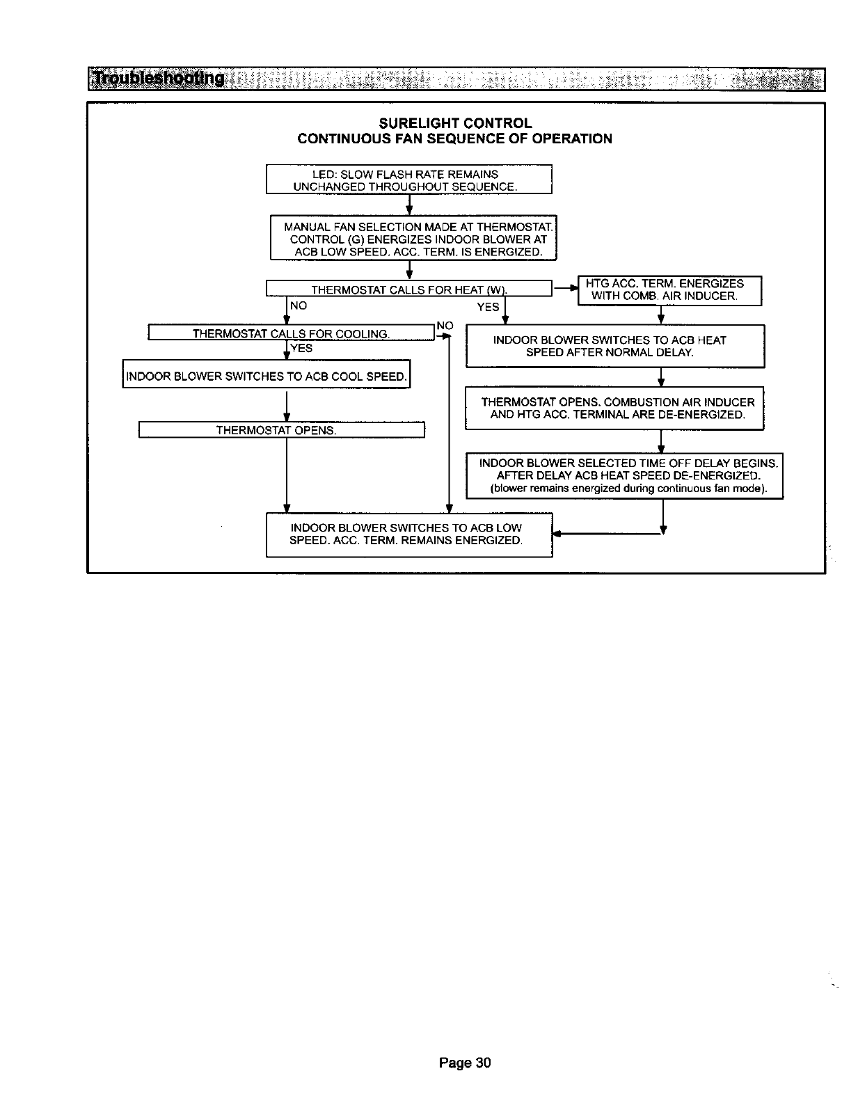
SURELIGHTCONTROL
CONTINUOUSFANSEQUENCEOFOPERATION
1
LED: SLOW FLASH RATE REMAINS I
UNCHANGED THROUGHOUT SEQUENCE. I
MANUAL FAN SELECTION MADE AT THERMOSTAT.
CONTROL (G) ENERGIZES INDOOR BLOWER AT
ACB LOW SPEED. ACC. TERM. IS ENERGIZED.
THERMOSTAT CALLS FOR HEAT (W}. ]_1_
/
NO
ITHERMOSTAT CALLS FOR COOLING.
_YES
IINDOOR BLOWER SWITCHES TO ACS COOL SPEED. I
I THERMOSTAT OPENS.
l
YES
INDOOR BLOWER SWITCHES TO ACB HEAT
SPEED AFTER NORMAL DELAY.
HTG ACC. TERM. ENERGIZES I
WITH COMB. AIR INDUCER. I
THERMOSTAT OPENS. COMBUSTION AIR INDUCER
AND HTG ACC. TERMINAL ARE DE-ENERGIZED.
INDOOR BLOWER SWITCHES TO ACB LOW
SPEED. ACC. TERM. REMAINS ENERGIZED.
INDOOR BLOWER SELECTED TIME OFF DELAY BEGINS.
AFTER DELAY ACB HEAT SPEED DE-ENERGIZED.
(blower remains energized during continuous fan mode).
Page 30
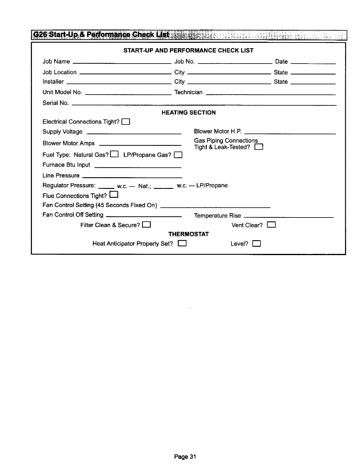
JobName
Job Location
Installer
Unit Model No.
Serial No.
START-UP AND PERFORMANCE CHECK LIST
Job No.
City
City
Technician
HEATING SECTION
Electrical Connections Tight? 17
Supply Voltage
Blower Motor Amps
Fuel Type: Natural Gas? [] LP/Propane Gas? []
Furnace Btu Input
Line Pressure
Regulator Pressure: __ w.c. -- Nat.; __
Flue Connections Tight? []
Fan Control Setting (45 Seconds Fixed On)
Fan Control Off Setting
Filter Clean & Secure? [_1
Date
State
State
Heat Anticipator Properly Set? []
Blower Motor H.P.
Gas Piping Connections
Tight & Leak-Tested? [--7
w.c. -- LP/Propane
Temperature Rise
Vent Clear?
THERMOSTAT
Level? []
Page 31
