LENNOX Air Handler (indoor Blower&evap) Manual L0805360
User Manual: LENNOX LENNOX Air Handler (indoor blower&evap) Manual LENNOX Air Handler (indoor blower&evap) Owner's Manual, LENNOX Air Handler (indoor blower&evap) installation guides
Open the PDF directly: View PDF ![]() .
.
Page Count: 4
Lithe U.S.A.
,1,_2001 Dallas, Texas, USA
INSTALLATION
INSTRUCTIONS
These instructions are for CB17-95, CBH17-95,
CB17-135, and CBH17-135. These instructions are in-
tended as a general guide and do not supersede national
or local codes in any way. Authorities having jurisdiction
should be consulted before installation.
CB17 & CBH17 Series Units
BLOWER COIL UNITS
504,588M F[_) Technical
2102 JJ.LL Publications
Supersedes 504,439M LithoUSA
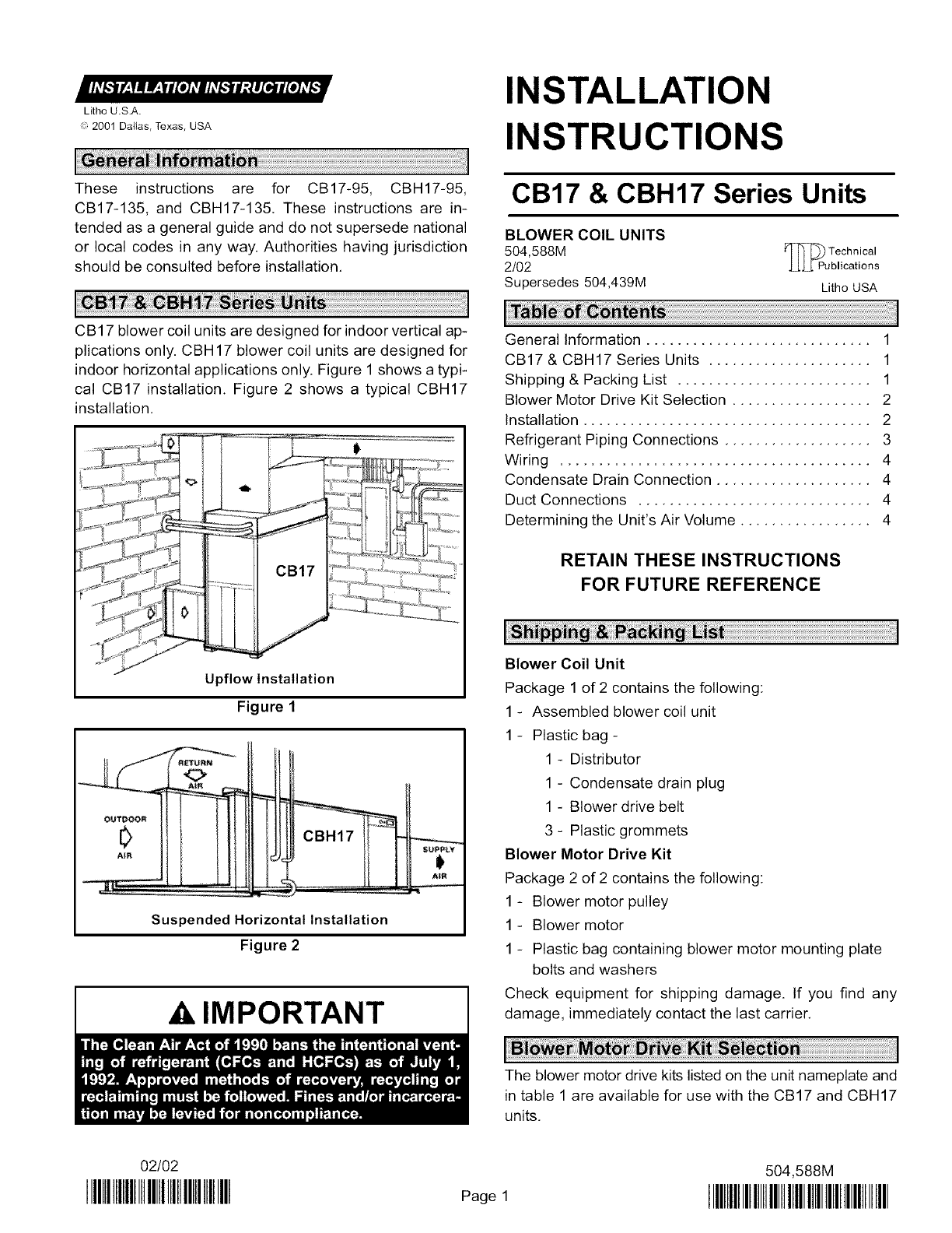
CB17 blower coil units are designed for indoor vertical ap-
plications only. CBH17 blower coil units are designed for
indoor horizontal applications only. Figure 1 shows a typi-
cal CB17 installation. Figure 2 shows a typical CBH17
installation.
Upflow Installation
Figure 1
,,,!
Suspended Horizontal Installation
Figure 2
IMPORTANT
General Information ............................. 1
CB17 & CBH17 Series Units ..................... 1
Shipping & Packing List ......................... 1
Blower Motor Drive Kit Selection .................. 2
Installation ..................................... 2
Refrigerant Piping Connections ................... 3
Wiring ........................................ 4
Condensate Drain Connection .................... 4
Duct Connections .............................. 4
Determining the Unit's Air Volume ................. 4
RETAIN THESE INSTRUCTIONS
FOR FUTURE REFERENCE
Blower Coil Unit
Package 1 of 2 contains the following:
1 - Assembled blower coil unit
1 - Plastic bag -
1 - Distributor
1 - Condensate drain plug
1 - Blower drive belt
3 - Plastic grommets
Blower Motor Drive Kit
Package 2 of 2 contains the following:
1 - Blower motor pulley
1-Blower motor
1 - Plastic bag containing blower motor mounting plate
bolts and washers
Check equipment for shipping damage. If you find any
damage, immediately contact the last carrier.
The blower motor drive kits listed on the unit nameplate and
in table 1 are available for use with the CB17 and CBH17
units.
02/02
IIIHlllllllllllllllllllllllllllllllll Page 1
504,588M
IIIHllllllllllllllllllllHlllllllllllllllllll
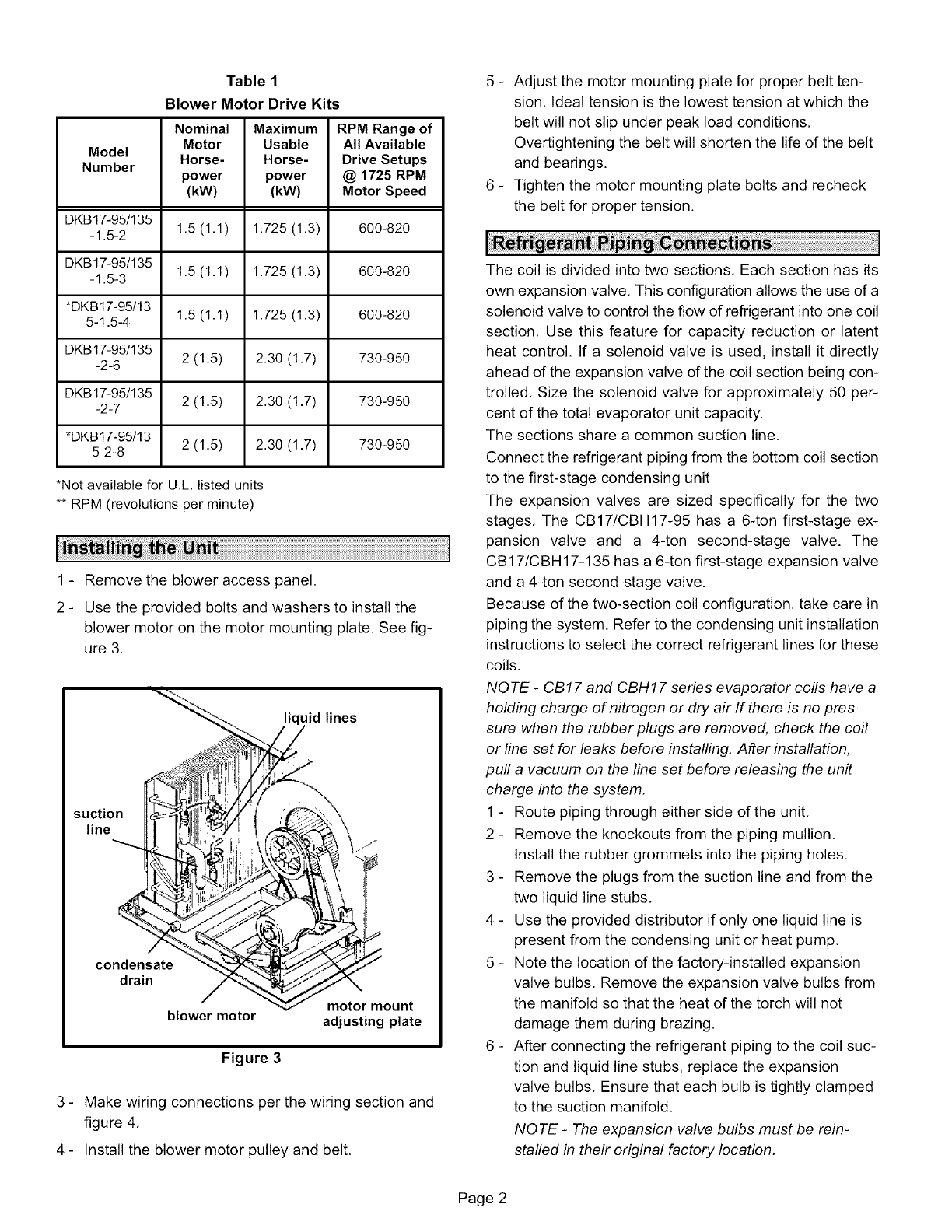
Table 1
Blower Motor Drive Kits
Nominal Maximum RPM Range of
Motor Usable All Available
Model Horse- Horse- Drive Setups
Number power power @ 1725 RPM
(kW) (kW) Motor Speed
DKB17-95/135
-1.5-2 1.5 (1.1) 1.725 (1.3) 600-820
DKB17-95/135
-1.5-3 1.5 (1.1) 1.725 (1.3) 600-820
*DKB17-95113
5-1.5-4 1.5 (1.1) 1.725 (1.3) 600-820
DKB 17-951135 2 (1.5) 2.30 (1.7) 730-950
-2-6
DKB 17-95/135 2 (1.5) 2.30 (1.7) 730-950
-2-7
*DKB17-95/13 2 (1.5) 2.30 (1.7) 730-950
5-2-8
*Not available for U.L. listed units
** RPM (revolutions per minute)
1 - Remove the blower access panel.
2 - Use the provided bolts and washers to install the
blower motor on the motor mounting plate. See fig-
ure 3.
=
liquidlines
suction _/' _/ :_ ,\
line ]_ [_U_ _ /
Ora'n moun,
blower motor adjusting plate
Figure 3
3 - Make wiring connections per the wiring section and
figure 4,
4 - Install the blower motor pulley and belt,
5 - Adjust the motor mounting plate for proper belt ten-
sion, Ideal tension is the lowest tension at which the
belt will not slip under peak load conditions,
Overtightening the belt will shorten the life of the belt
and bearings.
6 - Tighten the motor mounting plate bolts and recheck
the belt for proper tension.
The coil is divided into two sections, Each section has its
own expansion valve. This configuration allows the use of a
solenoid valve to control the flow of refrigerant into one coil
section, Use this feature for capacity reduction or latent
heat control. If a solenoid valve is used, install it directly
ahead of the expansion valve of the coil section being con-
trolled, Size the solenoid valve for approximately 50 per-
cent of the total evaporator unit capacity.
The sections share a common suction line,
Connect the refrigerant piping from the bottom coil section
to the first-stage condensing unit
The expansion valves are sized specifically for the two
stages, The CB17/CBH17-95 has a 6-ton first-stage ex-
pansion valve and a 4-ton second-stage valve. The
CB17/CBH 17-135 has a 6-ton first-stage expansion valve
and a 4-ton second-stage valve.
Because of the two-section coil configuration, take care in
piping the system. Refer to the condensing unit installation
instructions to select the correct refrigerant lines for these
coils,
NOTE -CB17 and CBH17 series evaporator coils have a
holding charge of nitrogen or dry air If there is no pres-
sure when the rubber plugs are removed, check the coil
or line set for leaks before installing, After installation,
pull a vacuum on the line set before releasing the unit
charge into the system,
1 - Route piping through either side of the unit.
2 - Remove the knockouts from the piping mullion.
Install the rubber grommets into the piping holes,
3 - Remove the plugs from the suction line and from the
two liquid line stubs,
4 - Use the provided distributor if only one liquid line is
present from the condensing unit or heat pump.
5 - Note the location of the factory-installed expansion
valve bulbs. Remove the expansion valve bulbs from
the manifold so that the heat of the torch will not
damage them during brazing.
6 - After connecting the refrigerant piping to the coil suc-
tion and liquid line stubs, replace the expansion
valve bulbs, Ensure that each bulb is tightly clamped
to the suction manifold.
NOTE -The expansion valve bulbs must be rein-
stalled in their original factory location,
Page 2
7- Insulatethesuctionlinewitha tubularslip-oninsula-
tion 2- Installtheplasticbushing,
3- Positiontheboxovertheplasticbushingandsecure
theblowercontactorkit(LB-51207CB),
NOTE -Complete all refrigerant piping connections be-
fore installing the blower contactor kit.
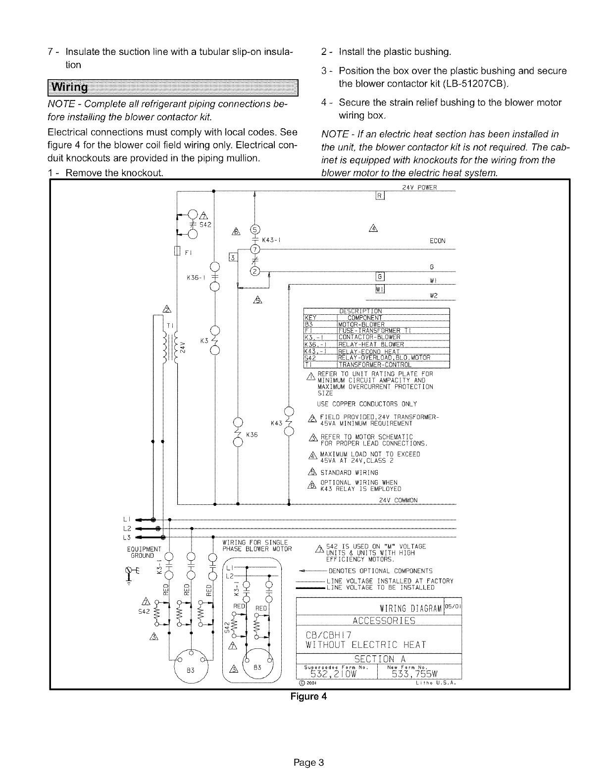
Electrical connections must comply with local codes. See
figure 4 for the blower coil field wiring only. Electrical con-
duit knockouts are provided in the piping mullion,
Remove the knockout,
A
I
4 - Secure the strain relief bushing to the blower motor
wiring box,
NOTE -If an electric heat section has been installed in
the unit, the blower contactor kit is not required. The cab-
inet is equipped with knockouts for the wiring from the
blower motor to the electric heat system.
S4
]rl
K36- I
,A
24V POWER
A
ECON
G
[] wl
W2
DESCRIPTION
[KEY COMPONENT
iB3 MOTOR-BLOWER
[FI FUSE-TRANSFORMER TI
<5,-I CONTACTOR-BLOWER
iK36,-I RELAY-HEAT BLOWER
iK43,-I RELAY-ECONO HEAT
[$42 RELAY-OVERLOAD,BLO.MOTOR
[TI TRANSFORMER-CONTROL
z_REFER TO UNIT RATING PLATE FOR
MINIMUM CIRCUIT AMPACITY AND
MAXIMUM OVERCURRENT PROTECTION
SIZE
USE COPPER CONDUCTORS ONLY
z_FIELD PROVIDEO,24V TRANSFORMER-
45VA MINIMUM REOUIREMENT
z_REFER TO MOTOR SCHEMATIC
FOR PROPER LEAD CONNECTIONS.
z_MAXIMUM LOAD NOT TO EXCEED
4OVA AT 24V,CLASS 2
z_STANDARD WIRING
Z_ OPTIONAL WIRING WHEN
K43 RELAY IS EMPLOYED
24V COMMON
:TTsWIRINGSINGLE
PHASE BLOWER MOTOR Z_542 IS USED ON "M" VOLTAGE
UNITS & UNITS WITH HIGH
_ :__LI _ DENOTES OPT IONAL COMPONENTS
--LINE VOLTAGE INSTALLED AT FACTORY
m m D _LINE VOLTAGE TO BE INSTALLED
LL_ LIJ LU
....
$42Z_? _ WIRING DIAGRAM
ACCESSORIES
CB/CBHU7
WITHOUT ELECTRIC HEAT
SECTION A
Supersedes Form No. | New Form No.
532,210W 553,755W
L[fho U,S,A,
Figure 4
Page 3
Theunitisequippedwithacondensatedrainoutletoneach
side.
1- Installtheprovideddrainpluginthecondensateout-
letthatwillnotbeused,
2- Installcondensatepipingusingproperlysizedfield-
providedfittings,
3_ Installatrapinthedrainlinewherethedrainexits
theunit,
4- Pitchthedrainlinedownwardtotheopendrainor
sump,
NOTE -Never connect the condensate drain to a
closed system,
5 - Use plugged tees where possible to facilitate clean-
ing the drain lines.
If a return air plenum is not used. installation codes may
limit installation to single-story structures only.
Table 2
Do not install the supply air plenum within 18 inches (457
mm) of the blower access panel,
NOTE -Use a flexible duct to eliminate vibration,
NOTE -The indoor coil must be dry and the air filters
must be in place when the following measurements are
taken.
1 - Run the blower without a cooling demand,
2 - Measure the static pressure external to the unit,
3 - Measure the indoor blower motor's rpm,
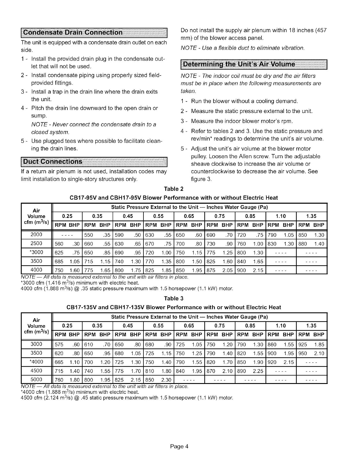
4 - Refer to tables 2 and 3, Use the static pressure and
rev/min* readings to determine the unit's air volume.
5 - Adjust the unit's air volume at the blower motor
pulley. Loosen the Allen screw, Turn the adjustable
sheave clockwise to increase the air volume or
counterclockwise to decrease the air volume. See
figure 3.
CB17-95V and CBH17-95V Blower Performance with or without Electric Heat
Static Pressure External to the Unit -- Inches Water Gauge (Pa)
0.25 0.35 0.45 0.55 0.65 0.75 0.85
Air
Volume 1.10 1.35
cfm (m3/s) RPM BHP RPM BHP RPM BHP RPM BHP RPM BHP RPM BHP RPM BHP RPM BHP RPM BHP
2000 .... 550 .35 590 .50 630 .55 650 .60 690 .70 720 .75 790 1.05 850 1.30
2500 560 .30 660 .55 630 .65 670 .75 700 .80 730 .90 760 1.00 830 1.30 880 1.40
*3000 625 .75 650 .85 690 .95 720 1.00 750 1.15 775 1.25 800 1.30 ........
3500 685 1.05 715 1.15 740 1.30 770 1.35 800 1.50 825 1.60 840 1.65 ........
4000 750 1.60 775 1.65 800 1.75 825 1.85 850 1.95 875 2.05 900 2.15 ........
NOTE -- Aft data is measured external to the unit with air filters in place.
*3000 cfm (1.416 m3/s) minimum with electric heat.
4000 cfm (1.888 m3ls) @ .35 static pressure maximum with 1.5 horsepower (1.1 kW) motor.
Table 3
CB17-135V and CBH17-135V Blower Performance with or without Electric Heat
Static Pressure External to the Unit -- Inches Water Gauge (Pa)
Air
Volume 0.25 0.35 0.45 0.55 0.65 0.75 0.85 1.10 1.35
cfm (m3/s) RPM BHP RPM BHP RPM BHP RPM BHP RPM BHP RPM BHP RPM BHP RPM BHP RPM BHP
3000 575 .60 610 .70 650 .80 680 .90 725 1.05 750 1.20 790 1.30 860 1.55 925 1.85
3500 620 .80 650 .95 680 1.05 725 1.15 750 1.25 790 1.40 820 1.55 900 1.95 950 2.10
*4000 665 1.10 700 1.20 725 1.30 750 1.40 790 1.55 820 1.70 850 1.90 920 2.15 ....
4500 715 1.40 740 1.55 775 1.70 810 1.80 840 1.95 870 2.10 890 2.25 ........
5000 760 1.80 800 1.95 825 2.15 850 2.30 ....................
NOTE -- Aft data is measured external to the unit with air filters in place.
*4000 cfm (1.888 m3/s) minimum with electric heat.
4500 cfm (2.124 m3/s) @ .45 static pressure maximum with 1.5 horsepower (1.1 kW) motor.
Page 4
