LENNOX Air Conditioner/heat Pump(outside Unit) Manual L0805463
User Manual: LENNOX LENNOX Air conditioner/heat pump(outside unit) Manual LENNOX Air conditioner/heat pump(outside unit) Owner's Manual, LENNOX Air conditioner/heat pump(outside unit) installation guides
Open the PDF directly: View PDF ![]() .
.
Page Count: 2
LENNOX
,t_2001 Lennox Industries Inc.
Dallas, Texas
KITS COMMON TO COOLING
AND HEAT PUMP EQUIPMENT
Fj_ puTeCh n ical
blications
Litho U.S.A.
504,316M
3/2001
Supersedes 503,874M
COMPRESSOR START KITS
INSTALLATION INSTRUCTIONS FOR COMPRESSOR START KITS
Package 1 of 1 contains the following:
1 - Start capacitor
1 - Potential relay
1 - Capacitor bracket
1 - Bag assembly including the following:
1 - # 8-32 x 3/8 TFS screw
2 -# 10-32 x 1/2 TFS screw
1 - Wiring diagram sticker
1 - Conversion sticker
Refer to the list of kits and corresponding compressors
which begins on page 2 to ensure the correct unit
application.
Single-phase condensing/heat pump units are equipped
with a PSC (Permanent Split Capacitor) single-phase
motor. In most cases, this motor does not require a
potential relay and starting capacitor. However,
conditions such as low voltage may require the use of a
start kit to increase compressor starting torque.
c- Install the mounting bracket using the provided
screw. Do not tighten screw completely.
d - Insert capacitor into bracket and tighten screw.
Capacitor should still move slightly in the bracket.
It should not fall beyond stop in control box.
5-Install the relay inside unit control box using the
provided screw (if necessary).
NOTE -Relay is position-sensitive. It must be
installed with the screw at the top.
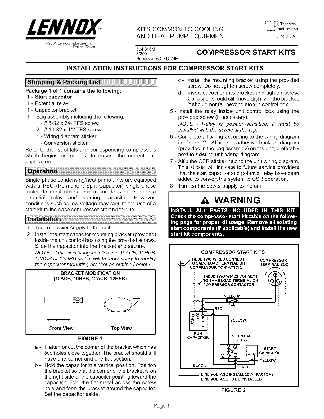
6 - Complete all wiring according to the wiring diagram
in figure 2. Affix the adhesive-backed diagram
(provided in the bag assembly) on the unit, preferably
next to existing unit wiring diagram.
7 - Affix the CSR sticker next to the unit wiring diagram.
This sticker will indicate to future service providers
that the start capacitor and potential relay have been
added to convert the system to CSR operation.
8 - Turn on the power supply to the unit.
WARNING
1 - Turn off power supply to the unit.
2 - Install the start capacitor mounting bracket (provided)
inside the unit control box using the provided screws.
Slide the capacitor into the bracket and secure.
NOTE -If the kit is being installed in a I OACB, 10HPB,
12ACB or 12HPB unit, it will be necessary to modify
the capacitor mounting bracket as outlined below.
BRACKET MODIFICATION
(10ACB, 10HPB, 12ACB, 12HPB)
Front View Top View
a -
b _
FIGURE 1
Flatten or cut the corner of the bracket which has
two holes close together. The bracket should still
have one corner and one flat section.
Hold the capacitor in a vertical position. Position
the bracket so that the corner of the bracket is on
the right side of the capacitor pointing toward the
capacitor, Fold the flat metal across the screw
hole and form the bracket around the capacitor.
Set the capacitor aside.
COMPRESSOR START KITS
.THESE TWO WIRES CONNECT COMPRESSOR
_TO SAME LOAD TERMINAL ON TERMINAL BOX
/ cOMPRESSORCONTACTOR''I /_
/ I I THESE TWO WIRES CONNECT I t"_ _
| U/TOsAMELOADTERMINALON I k@l@) I
/ _COMPRESSOR CONTACTOR.
l I IYELLOW I II
BLACK -- I I
RED RED
RUN
CAPACITOR
BLACK
YELLOW
POTENTIAL
LAY
START
CAPACITOR
YELLOW
LINE VOLTAGE INSTALLED AT FACTORY
LINE VOLTAGE TO BE INSTALLED
FIGURE 2
Page 1
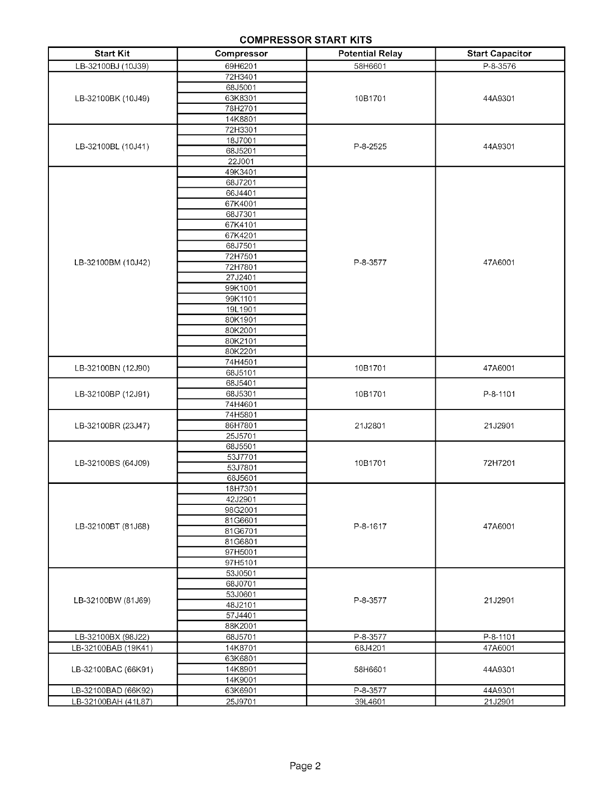
Start Kit Potential Relay Start Capacitor
LB-32100BJ (10J39) 58H6601 P-8-3576
LB-32100BK (10J49)
LB-32100BL(10J41)
LB-32100BM (10J42)
LB-32100BN (12J90)
LB-32100BP (12J91)
LB-32100BR (23J47)
LB-32100BS (64J09)
LB-32100BT (81J68)
LB-32100BW(81J69)
LB-32100BX (98J22)
LB-32100BAB (19K41)
LB-32100BAC (66K91)
LB-32100BAD (66K92)
LB-32100BAH (41L87)
COMPRESSOR START KITS
Compressor
69H6201
72H3401
68J5001
63K8301
78H2701
14K8801
72H3301
18J7001
68J5201
22J001
49K3401
68J7201
66J4401
67K4001
68J7301
67K4101
67K4201
68J7501
72H7501
72H7801
27J2401
99K1001
99Kl101
19L1901
80K1901
80K2001
80K2101
80K2201
74H4501
68J5101
68J5401
68J5301
74H4601
74H5801
86H7801
25J5701
68J5501
53J7701
53J7801
68J5601
18H7301
42J2901
98G2001
81G6601
81G6701
81G6801
97H5001
97H5101
53J0501
68J0701
53J0601
48J2101
57J4401
88K2001
68J5701
14K8701
63K6801
14K8901
14K9001
63K6901
25J9701
10B1701
P-8-2525
P-8-3577
10B1701
10B1701
21J2801
10B1701
P-8-1617
44A9301
44A9301
47A6001
47A6001
P-8-1101
21J2901
72H7201
47A6001
P-8-3577 21J2901
P-8-3577 P-8-1101
68J4201 47A6001
58H6601 44A9301
P-8-3577 44A9301
39L4601 21J2901
Page 2
