LENNOX Air Conditioner/heat Pump(outside Unit) Manual L0805469
User Manual: LENNOX LENNOX Air conditioner/heat pump(outside unit) Manual LENNOX Air conditioner/heat pump(outside unit) Owner's Manual, LENNOX Air conditioner/heat pump(outside unit) installation guides
Open the PDF directly: View PDF ![]() .
.
Page Count: 4
LENNOX
,_,_2002 Lennox Industries inc,
DaiIas, Texas, USA
COOLING KITS AND ACCESSORIES Fj_ppuTeCh n ical
blications
Lithe U.S.A.
504,664M
08/03
Supersedes 02/03 CONDENSER COIL
REPLACEMENT KIT
INSTALLATION INSTRUCTIONS FOR REPLACEMENT CONDENSER COIL FOR
HS26-030,-036,-042,-048,-060; HS27-024,-030,-036, &-042; HSXA15-060,
HSXB15-024, -030, -036, -042,-048, -060; & HSXA19-036, 038, 048, -060 SERIES UNITS
Package 1 of 1 contains:
1 - Condenser coil
1 - Bag assembly for use with the following units:
HS26-030, -036, -042,-048, & -060; HS27-024, -030,
-036, &-042; HSXA15-060; & HSXB16-060
1 - Discharge line with elbow
1 - Liquid line adapter
All other units:
1 - 1/2" Coupling
Check the replacement coil for shipping damage. If you
find any damage, immediately contact the last carrier.
Verify that the coil has holding charge. Remove the cap
from the discharge stub and press the valve core. The coil
should have approximately 10 psi dry air holding charge.
If there is no charge, repressurize the coil and check for
leaks.
Verify that the liquid and discharge manifold is straight
and that the tubing is not displaced. Be extremely careful
with the stub for the common liquid line. Do not twist or
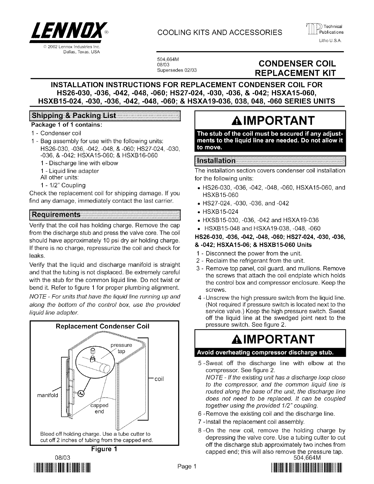
bend it. Refer to figure 1 for proper plumbing alignment.
NOTE -For units that have the fiquid line running up and
along the bottom of the control box, use the provided
liquid line adapter.
Replacement Condenser Coil
,._'_J ___'_ _'la
manifold
end
Bleed off holding charge. Use a tube cutter to
cut off 2 inches of tubing from the capped end.
Figure 1
08/03
IIIHIIIIIIIIIIIIIIIIIIIIIIIIIIIIIIIII Page 1
AI,IMPORTANT
The installation section covers condenser coil installation
for the following units:
• HS26-030, -036, -042, -048, -060, HSXA15-060, and
HSXB15-060
• HS27-024, -030, -036, and -042
• HSXB15-024
• HXSB15-030, -036, -042 and HSXA19-036
• HSXB15-048 and HSXA19-038, -048, -060
HS26-030, -036, -042,-048,-060; HS27-024,-030,-036,
& -042; HSXA15-06; & HSXB15-060 Units
1 - Disconnect the power from the unit.
2
3- Reclaim the refrigerant from the unit.
- Remove top panel, coil guard, and mullions. Remove
the screws that attach the coil endplate which holds
the control box and compressor enclosure. Keep the
screws.
-Unscrew the high pressure switch from the liquid line.
(Not required if pressure switch is located next to the
service valve.) Keep the high pressure switch. Sweat
off the liquid line at the swedged joint next to the
pressure switch. See figure 2.
AI,IMPORTANT
5-Sweat off the discharge line with elbow at the
compressor. See figure 2.
NOTE -If the existing unit has a discharge loop close
to the compressor, and the common liquid line is
routed along the base of the unit, the discharge line
does not need to be replaced. It can be coupled
together using the provided 1/2" coupling.
6 -Remove the existing coil and the discharge line.
7 -Install the replacement coil assembly.
8-On the new coil, remove the holding charge by
depressing the valve core. Use a tubing cutter to cut
off the discharge stub approximately two inches from
capped end; this will also remove the pressure tap.
504,664M
IIIHIIIIIIIIIIIIIIIIIIIIIllllllllllllllllllllll
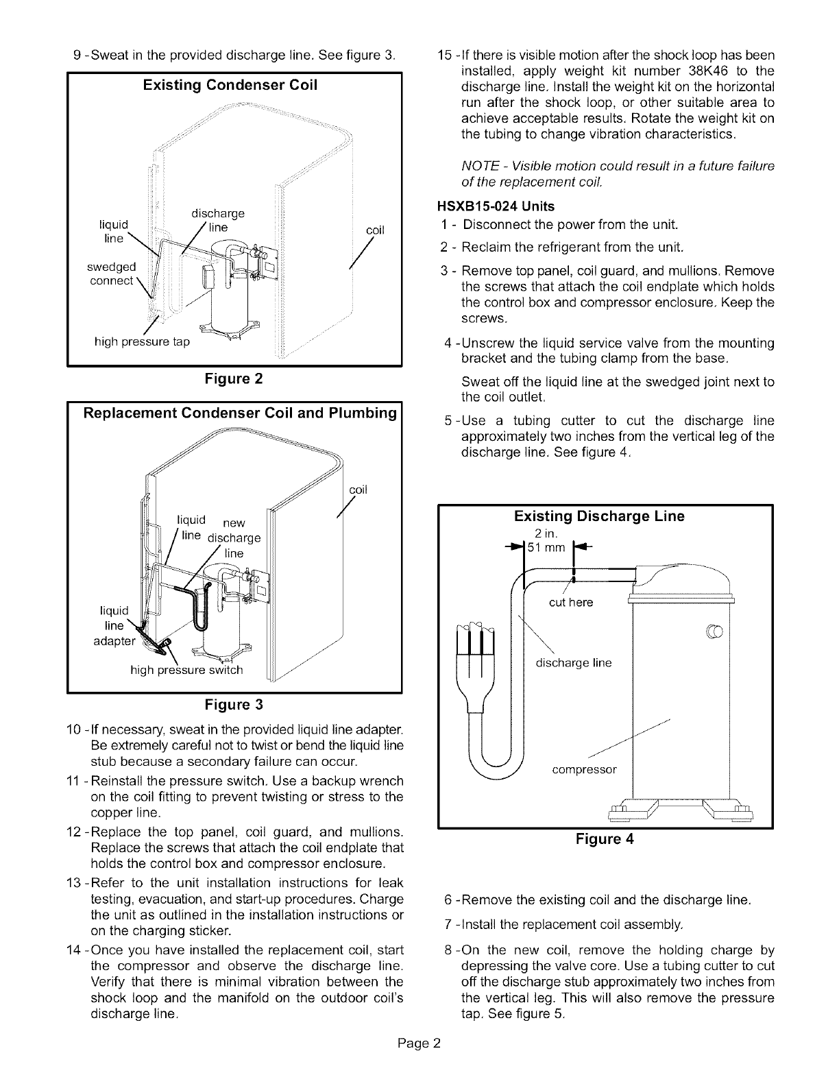
9 -Sweat in the provided discharge line. See figure 3,
Existing Condenser Coil
f'i!_ii_i:ii _i_
discharge
liquid
line \ coil
swedged
connect \
high pressure tap
Figure 2
Replacement Condenser Coil and Plumbing
line
coil
liquid
line
/
/
/
high pressure switch /
Figure 3
10 -If necessary, sweat in the provided liquid line adapter.
Be extremely careful not to twist or bend the liquid line
stub because a secondary failure can occur,
11 - Reinstall the pressure switch, Use a backup wrench
on the coil fitting to prevent twisting or stress to the
copper line.
12-Replace the top panel, coil guard, and mullions.
Replace the screws that attach the coil endplate that
holds the control box and compressor enclosure,
13-Refer to the unit installation instructions for leak
testing, evacuation, and start-up procedures. Charge
the unit as outlined in the installation instructions or
on the charging sticker.
14 -Once you have installed the replacement coil, start
the compressor and observe the discharge line.
Verify that there is minimal vibration between the
shock loop and the manifold on the outdoor coil's
discharge line,
15 -If there is visible motion after the shock loop has been
installed, apply weight kit number 38K46 to the
discharge line, Install the weight kit on the horizontal
run after the shock loop, or other suitable area to
achieve acceptable results, Rotate the weight kit on
the tubing to change vibration characteristics,
NOTE -Visible motion could result in a future failure
of the replacement coil.
HSXB15-024 Units
1 - Disconnect the power from the unit,
2 - Reclaim the refrigerant from the unit,
3 - Remove top panel, coil guard, and mullions. Remove
the screws that attach the coil endplate which holds
the control box and compressor enclosure, Keep the
screws,
4 -Unscrew the liquid service valve from the mounting
bracket and the tubing clamp from the base,
Sweat off the liquid line at the swedged joint next to
the coil outlet.
5-Use a tubing cutter to cut the discharge line
approximately two inches from the vertical leg of the
discharge line. See figure 4,
Existing Discharge Line
2 in.
51 mm _-
cut here
discharge line
compressor
Figure 4
6 -Remove the existing coil and the discharge line,
7 -Install the replacement coil assembly,
8-On the new coil, remove the holding charge by
depressing the valve core, Use a tubing cutter to cut
off the discharge stub approximately two inches from
the vertical leg. This will also remove the pressure
tap, See figure 5,
Page 2
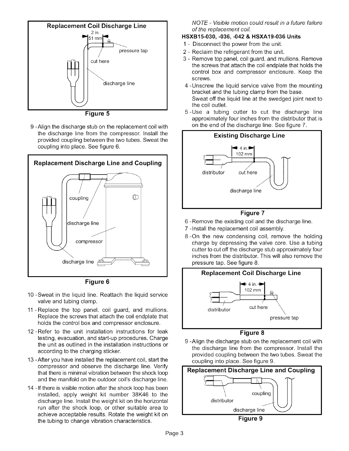
Replacement Coil Discharge Line
2in,
pressure tap
cut here
discharge line
Figure 5
9 -Align the discharge stub on the replacement coil with
the discharge line from the compressor. Install the
provided coupling between the two tubes. Sweat the
coupling into place. See figure 6.
Replacement Discharge Line and Coupling
lcoupli
discharge line /
compressor
\\
discharge line _
Figure 6
10 -Sweat in the liquid line. Reattach the liquid service
valve and tubing clamp.
11-Replace the top panel, coil guard, and mullions.
Replace the screws that attach the coil endplate that
holds the control box and compressor enclosure.
12-Refer to the unit installation instructions for leak
testing, evacuation, and start-up procedures. Charge
the unit as outlined in the installation instructions or
according to the charging sticker.
13 -After you have installed the replacement coil, start the
compressor and observe the discharge line. Verify
that there is minimal vibration between the shock loop
and the manifold on the outdoor coil's discharge line.
14 - If there is visible motion after the shock loop has been
installed, apply weight kit number 38K46 to the
discharge line. Install the weight kit on the horizontal
run after the shock loop, or other suitable area to
achieve acceptable results. Rotate the weight kit on
the tubing to change vibration characteristics.
NOTE -Visible motion could result in a future failure
of the replacement coil,
HSXB15-030, -036, -042 & HSXA19-036 Units
1 - Disconnect the power from the unit.
2 - Reclaim the refrigerant from the unit.
3 - Remove top panel, coil guard, and mullions, Remove
the screws that attach the coil endplate that holds the
control box and compressor enclosure, Keep the
screws.
4 -Unscrew the liquid service valve from the mounting
bracket and the tubing clamp from the base.
Sweat off the liquid line at the swedged joint next to
the coil outlet.
5-Use a tubing cutter to cut the discharge line
approximately four inches from the distributor that is
on the end of the discharge line. See figure 7.
Existing Discharge Line
_1 4 in,D1
02 mm I
j'
distributor cut here
discharge line
Figure 7
6 -Remove the existing coil and the discharge line.
7 -Install the replacement coil assembly.
8-On the new condensing coil, remove the holding
charge by depressing the valve core. Use a tubing
cutter to cut off the discharge stub approximately four
inches from the distributor. This will also remove the
pressure tap. See figure 8.
Replacement Coil Discharge Line
_1 4 in.-_
02 mm I
/I \I
\
cut here
distributor x
pressure tap
Figure 8
9 -Align the discharge stub on the replacement coil with
the discharge line from the compressor. Install the
provided coupling between the two tubes. Sweat the
coupling into place. See figure 9.
Replacement Discharge Line and Coupling
c°up"nglt II
distribut°rdischarge line__
Figure 9
Page 3
10-Sweatintheliquidline,Reattachtheliquidservice
valveandtubingclamp.
11-Replacethe top panel,coil guard,and mullions.
Replacethescrewsthatattachthecoilendplatethat
holdsthecontrolboxandcompressorenclosure.
12-Referto the unitinstallationinstructionsfor leak
testing,evacuation,andstart-upprocedures.Charge
theunitasoutlinedintheinstallationinstructionsor
accordingtothechargingsticker.
13-Onceyouhaveinstalledthereplacementcoil,start
the compressorand observethe dischargeline.
Verifythatthereis minimalvibrationbetweenthe
shockloopandthemanifoldonthe outdoorcoil's
dischargeline.
14-Ifthereisvisiblemotionaftertheshockloophasbeen
installed,applyweightkit number38K46to the
dischargeline,Installtheweightkitonthehorizontal
runafterthe shockloop,or othersuitableareato
achieveacceptableresults,Rotatetheweightkiton
thetubingtochangevibrationcharacteristics.
NOTE -Visible motion could result in a future failure
of the replacement coil.
HSXB15-048 & HSXA19-038, -048, -060 Units
1 - Disconnect the power from the unit.
2 - Reclaim the refrigerant from the unit.
3 - Remove top panel, coil guard, and mullions. Remove
the screws that attach the coil endplate which holds
the control box and compressor enclosure. Keep the
screws.
4-Unscrew the liquid service valve from mounting
bracket and the tubing clamp from the base, Sweat
off the liquid line at the swedged joint next to the coil
outlet,
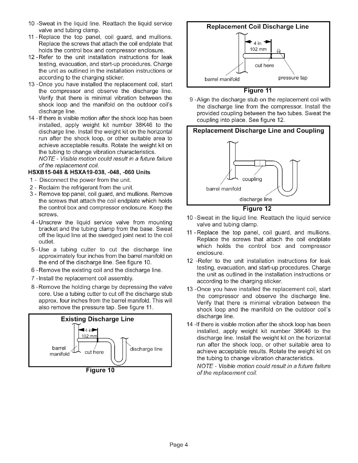
5-Use a tubing cutter to cut the discharge line
approximately four inches from the barrel manifold on
the end of the discharge line. See figure 10,
6 -Remove the existing coil and the discharge line,
7 -Install the replacement coil assembly.
8 -Remove the holding charge by depressing the valve
core. Use a tubing cutter to cut off the discharge stub
approx, four inches from the barrel manifold, This will
also remove the pressure tap, See figure 11,
Existing Discharge Line
T 4 I
barrel /_t0:u:1:! _discharge line
manifold re
Figure 10
Replacement Coil Discharge Line
J
barrel manifold
4 in "111
102 mm I
/_ \1
cut here _
pressure tap
Figure 11
9 -Align the discharge stub on the replacement coil with
the discharge line from the compressor. Install the
provided coupling between the two tubes, Sweat the
coupling into place, See figure 12,
Replacement Discharge Line and Coupling
/coupling
barrel manifold
discharge line
Figure 12
10-Sweat in the liquid line. Reattach the liquid service
valve and tubing clamp.
11-Replace the top panel, coil guard, and mullions.
Replace the screws that attach the coil endplate
which holds the control box and compressor
enclosure.
12 -Refer to the unit installation instructions for leak
testing, evacuation, and start-up procedures. Charge
the unit as outlined in the installation instructions or
according to the charging sticker.
13 -Once you have installed the replacement coil, start
the compressor and observe the discharge line.
Verify that there is minimal vibration between the
shock loop and the manifold on the outdoor coil's
discharge line.
14 -If there is visible motion after the shock loop has been
installed, apply weight kit number 38K46 to the
discharge line. Install the weight kit on the horizontal
run after the shock loop, or other suitable area to
achieve acceptable results, Rotate the weight kit on
the tubing to change vibration characteristics,
NOTE -Visible motion could result in a future failure
of the replacement coil.
Page 4
