LENNOX Air Conditioner/heat Pump(outside Unit) Manual L0805474
User Manual: LENNOX LENNOX Air conditioner/heat pump(outside unit) Manual LENNOX Air conditioner/heat pump(outside unit) Owner's Manual, LENNOX Air conditioner/heat pump(outside unit) installation guides
Open the PDF directly: View PDF ![]() .
.
Page Count: 14
,?u2006 Lennox Industries Inc+
Dallas, Texas, USA
INSTALLATION
INSTRUCTIONS
HS29 Series Units
CONDENSING UNITS _ Technical
504,963M LL.L[ Publications
03/06 Litho U.S.A.
Supersedes 09/04
RETAIN THESE INSTRUCTIONS
FOR FUTURE REFERENCE
X_ WARNING
_l_ IMPORTANT
Elite® Series Outdoor Unit ...................... 1
General Information ........................... 1
Shipping & Packing List ........................ 1
Unit Dimensions - inches (mm) .................. 2
Setting the Unit ............................... 2
Electrical ..................................... 3
Refrigerant Piping ............................. 4
Fixed Refrigerant Metering Device ............... 6
Manifold Gauge Set ........................... 7
Service Valves ................................ 7
Leak Testing .................................. 8
Evacuation ................................... 8
Start-Up ...................................... 9
Charging ..................................... 9
System Operation ............................. 13
Maintenance .................................. 12
Optional Accessories .......................... 13
Start-Up & Performance Check List .............. 13
HS29 Elite® Series outdoor units are designed for expan-
sion valve (TXV) and fixed orifice systems, Refer to Lennox
engineering handbook for expansion valve kits which must
be ordered separately.
X_ WARNING
03/06
IIIB+IIIIIIIIIIIHIBIIIIIlll
1 -Assembled HS29 outdoor unit
1-Fixed orifice refrigerant metering device
1 -Coupling, 5/16 x 3/8" (012,018, 024, 030)
1 - Sight Glass (international units only)
Check equipment for shipping damage. If you find any
damage, immediately contact the last carrier.
_1_CAUTION
These instructions are intended as a general guide and do
not supersede national or local codes in any way+ Consult
authorities having jurisdiction before installation+
Page 1 504,963M
IIIIIIIIIIIIIIIIIIIIIIIIIIIIBBIIIIIIIlll
When servicing or repairing HVAC components, ensure
the fasteners are appropriately tightened, Table 1 shows
torque values for fasteners.
Table 1
Torque Requirements
Part Recommended Torque
Service valve cap 8 ft.- lb. 11NM
Sheet metal screws 16 in.- lb. 2 NM
Machine screws #10 28 in.- lb. 3 NM
Compressor bolts 90 in.- lb. 10 NM
Gauge port seal cap 8 ft.- lb. 11NM
CAUTION
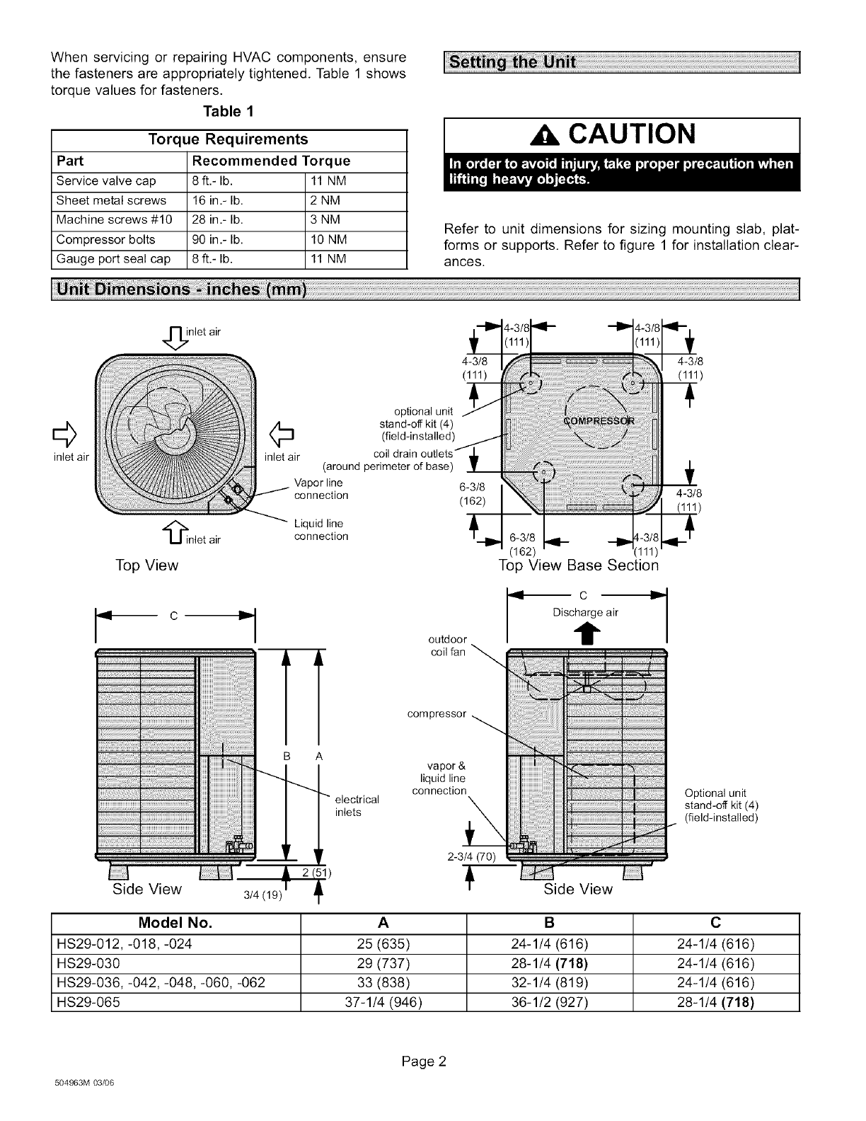
Refer to unit dimensions for sizing mounting slab, plat-
forms or supports. Refer to figure 1 for installation clear-
ances.
,_nlet air
4-3/8 4-3/8
(111) (111)
©
inlet air
_inlet air
optional unit
(_ stand-off kit (4)
(field-installed)
inlet air coil drain
(around perimeter of base)
Vapor line 6-3/8
connection (162)
Liquid line
connection
Top View Top View Base Section
l-d Ci,._l c
Discharge air
outdoor t
coil fan
%.
compressor
A
electrical
inlets
vapor &
liquid line
connection
2-3/4 (70)
Side View 3/4(191 Side View
4-3/8
!)
Optional unit
stand-off kit (4)
(field-installed)
Model No. AB C
HS29-012,-018,-024 25 (635) 24-1/4 (616) 24-1/4 (616)
HS29-030 29 (737) 28-1/4 (718) 24-1/4 (616)
HS29-036,-042,-048,-060, -062 33 (838) 32-1/4 (819) 24-1/4 (616)
HS29-065 37-1/4 (946) 36-1/2 (927) 28-1/4 (718)
504963M 03/06
Page 2
Installation Clearances
36 (914
mm)
36* (914
ram)
36* (914 ram)
*A service clearance of 30" (762 mm) must be main-
tained on one of the sides adjacent to the control box.
Clearance to one of the other three sides must be 36"
(914 mm). Clearance to one of the remaining two sides
may be 12" (304 mm) and the final side may be 6" (152
mm).
A clearance of 24" (610 mm) must be maintained be-
tween two units. 48" (1219 mm) clearance required on
top of un#. Maximum soffit overhang is 36" (914 mm).
Figure 1
Slab Mounting
When installing unit at grade level, install on a level slab
high enough above grade to allow adequate drainage of
water. Locate the top of the slab so run-off water from high-
er ground will not collect around the unit,
Roof Mounting
Install unit at a minimum of 4 inches above the surface of
the roof. Ensure that the weight of unit is properly distrib-
uted over roof joists and rafters. Either redwood or steel
supports are recommended.
In the U.S.A., wiring must conform with current local codes
and the current National Electric Code (NEC). In Canada,
wiring must conform with current local codes and the current
Canadian Electrical Code (CEC).
_WARNING
Refer to the furnace or blower coil installation instructions
for additional wiring application diagrams and refer to unit
nameplate for minimum circuit ampacity and maximum
overcurrent protection size.
1. Install line voltage power supply to unit from a properly
sized disconnect switch.
2. Ground unit at unit disconnect switch or to an earth
ground.
NOTES -
• To facilitate conduit, a hole is in the bottom of
the control box. Connect conduit to the control box
using a proper conduit fitting.
• Units are approved for use onlywith coppercon-
ductors.
• 24V, Class II circuit connections are made in the
low voltage junction box. Refer to figure 2 for field
wiring diagram.
• A complete unit wiring diagram is located inside
the unit control box cover.
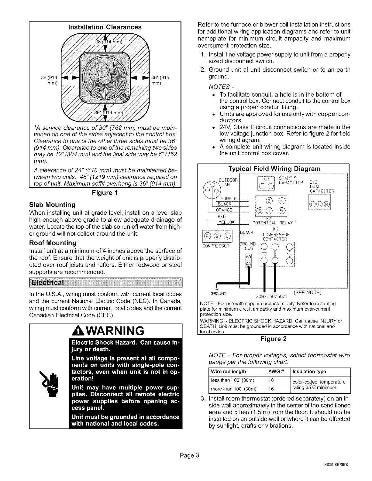
Typical Field Wiring Diagram
_0_!_ TDOOR
FAN
URPLE
RED
YELLOW
COMPRESSOR
START*
CAPACITOR
KSI
POTENTIAL RELAY *
KI
COMPRESSOR
CONTACTOR
GROUND
LUG
CI2
DUAL
CAPACITOR
G_UND (SEE NOTE)
208=250/60/I
NOTE - For use with copper conductors only. Refer to unit rating
plate for minimum circuit ampacity and maximum over-current
protection size.
WARNING! - ELECTRIC SHOCK HAZARD. Can cause INJURY or
DEATH. Unit must be grounded in accordance with national and
local codes.
Figure 2
.
NOTE -For proper voltages, select thermostat wire
gauge per the following chart:
Wire run length AWG # Insulation type
less than 100' (30m) 18 color-coded,o temperature
more than 100' (30m) 16 rating 35 C minimum
Install room thermostat (ordered separately) on an in-
side wall approximately in the center dthe conditioned
area and 5 feet (1.5 m) from the floor. It should not be
installed on an outside wall or where it can be effected
by sunlight, drafts or vibrations.
Page 3
HS29 SERIES
4, Install low voltage wiring from outdoor to indoor unit
and from thermostat to indoor unit, See figure 3,
Typical Low Voltage Field Wiring
Thermostat Indoor Unit
@
®
Q
Q
Q
power
heat
cooling
indoor blower
common
Outdoor Unit
Y1 Outdoor
Unit
/_C OutdoorUnit
NOTE - see unit wiring diagram for power supply connections.
NOTE - If the indoor unit is not equipped with blower relay. It must
be field-provided and installed (P-8-3251 or equivalent).
Figure 3
NOTE -Units are designed for line sets of up to fifty feet (15 m). For
appfications longer than fifty feet, consult the Lennox Refrigerant
Piping Guide (Corp. 9351-L9). Select line set diameters from
table 2to ensure that oil returns to the compressor.
Installing Refrigerant Line
During the installation of any heat pump or a/c system, it is
important to properly isolate the refrigerant lines to prevent
unnecessary vibration. Line set contact with the structure
(wall, ceiling or floor) causes some objectionable noise
when vibration is translated into sound, As a result, more
energy or vibration can be expected, Closer attention to
line set isolation must be observed.
Following are some points to consider when placing and
installing a high-efficiency outdoor unit:
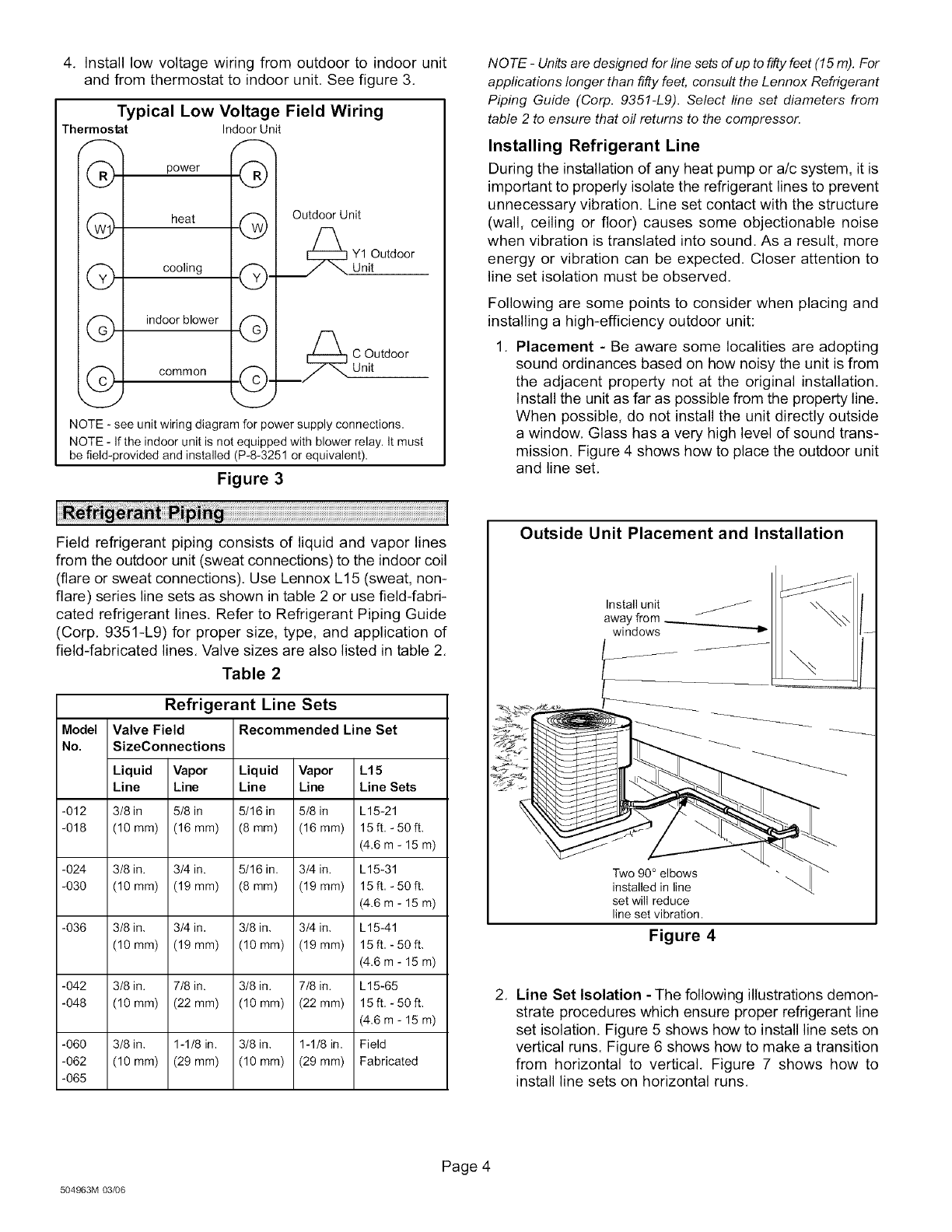
1, Placement - Be aware some localities are adopting
sound ordinances based on how noisy the unit is from
the adjacent property not at the original installation.
Install the unit as far as possible from the property line.
When possible, do not install the unit directly outside
a window, Glass has a very high level of sound trans-
mission. Figure 4 shows how to place the outdoor unit
and line set,
Field refrigerant piping consists of liquid and vapor lines
from the outdoor unit (sweat connections) to the indoor coil
(flare or sweat connections). Use Lennox L15 (sweat, non-
flare) series line sets as shown in table 2 or use field-fabri-
cated refrigerant lines, Refer to Refrigerant Piping Guide
(Corp, 9351-L9) for proper size, type, and application of
field-fabricated lines. Valve sizes are also listed in table 2,
Table 2
Refrigerant Line Sets
Model Valve Field
No. SizeConnections
Liquid Vapor
Line Line
-012 3/8 in 5/8 in
-018 (10 mm) (16 mm)
-024 3/8 in. 3/4 in.
-030 (10 mm) (19 mm)
-036 3/8 in, 3/4 in,
(10mm) (19mm)
-042 3/8 in. 7/8 in.
-048 (10 mm) (22 mm)
-060 3/8 in, 1-1/8 in,
-062 (10 mm) (29 mm)
-065
Recommended Line Set
Liquid Vapor L15
Line Line Line Sets
5/16 in 5/8 in L15-21
(8ram) (16 mm) 15 ft, - 50 ft,
(4.6 m - 15 m)
5/16 in, 3/4 in. L15-31
(8mm) (19 mm) 15 ft, - 50 ft,
(4.6 m - 15 m)
3/8 in, 3/4 in, L15-41
(lOmm) (19mm) 15ft,-50ft,
(4.6 m - 15 m)
3/8 in. 7/8 in. L15-65
(10mm) (22mm) 15ft,-50ft.
(4.6 m - 15 m)
3/8 in, 1-1/8 in, Field
(10 mm) (29 mm) Fabricated
Outside Unit Placement and Installation
Install unit
away from
windows "_
Two 90 °
installed in line
set will reduce
line set vibration.
Figure 4
2, Line Set Isolation -The following illustrations demon-
strate procedures which ensure proper refrigerant line
set isolation. Figure 5 shows how to install line sets on
vertical runs. Figure 6 shows how to make a transition
from horizontal to vertical, Figure 7 shows how to
install line sets on horizontal runs,
504963M 03/06
Page 4
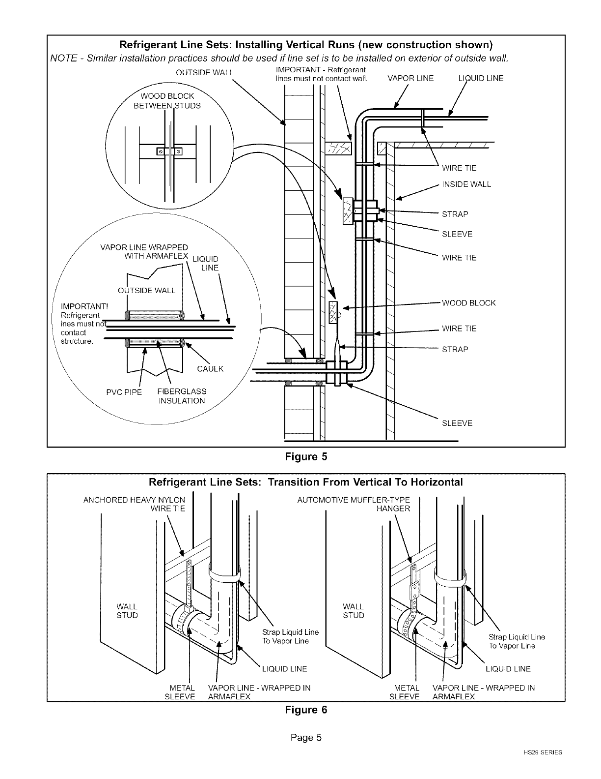
Refrigerant Line Sets: Installing Vertical Runs (new construction shown)
NOTE -Similar installation practices should be used if line set is to be installed on exterior of outside wall.
IMPORTANT!
Refrigerant
ines must not
contact
structure.
OUTSIDE WALL IMPORTANT - Refrigerant
lines must not contact wall.
VAPOR LINE WRAPPED
WITH ARMAFLEX LIQUID
[_'_ _- LINE
o \ IX,
[_ CAULK
PVC PIPE FIBERGLASS
INSULATION
VAPOR LINE LI UID LINE
-_. WIRE TIE
INSIDE WALL
- STRAP
SLEEVE
"_- WIRE TIE
"_ ----------WOOD BLOCK
_. _ WIRE TIE
STRAP
SLEEVE
Refrigerant Line Sets:
ANCHORED HEAVY NYLON
WIRE TIE
Figure 5
Transition From Vertical To Horizontal
AUTOMOTIVE MUFFLER-TYPE
HANGER
WALL
STUD
METAL
SLEEVE
Strap Liquid Line
To Vapor Line
LIQUID LINE
WALL
STUD
Strap Liquid Line
To Vapor Line
VAPOR LINE -WRAPPED IN METAL
ARMAFLEX SLEEVE
Figure 6
LIQUID LINE
VAPOR LINE - WRAPPED IN
ARMAFLEX
Page 5
HS29 SERIES
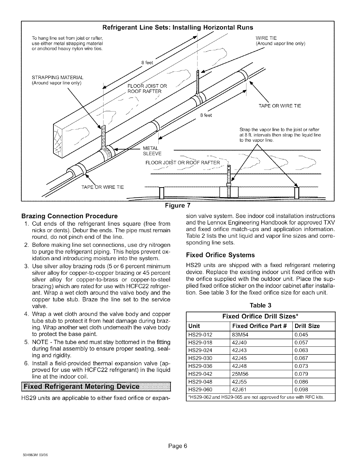
Refrigerant Line Sets: Installing Horizontal Runs
To hang line set from joist or rafter,
use either metal strapping material
or anchored heavy nylon wire ties.
8 feet
WIRE TIE
(Around vapor line only)
STRAPPING MATERIAL
(Around vapor line only) FLOOR JOIST OR
ROOF RAFTER
F\
/
/
J8 feet
\TAPE OR WIRE TIE
Strap the vapor line to the joist or rafter
at 8 ft. intervals then strap the liquid line
to the vapor line.
M ETAL
SLEEVE
FLOOR JOIST OR ROOF RAFTER ?
Figure 7
Brazing Connection Procedure
1, Cut ends of the refrigerant lines square (free from
nicks or dents), Debur the ends, The pipe must remain
round, do not pinch end of the line.
2, Before making line set connections, use dry nitrogen
to purge the refrigerant piping. This helps prevent ox-
idation and introducing moisture into the system.
3, Use silver alloy brazing rods (5 or 6 percent minimum
silver alloy for copper-to-copper brazing or 45 percent
silver alloy for copper-to-brass or copper-to-steel
brazing) which are rated for use with HCFC22 refriger-
ant. Wrap a wet cloth around the valve body and the
copper tube stub, Braze the line set to the service
valve,
4. Wrap a wet cloth around the valve body and copper
tube stub to protect it from heat damage during braz-
ing, Wrap another wet cloth underneath the valve body
to protect the base paint.
5. NOTE - The tube end must stay bottomed in the fitting
during final assembly to ensure proper seating, seal-
ing and rigidity.
6. Install a field-provided thermal expansion valve (ap-
proved for use with HCFC22 refrigerant) in the liquid
line at the indoor coil,
HS29 units are applicable to either fixed orifice or expan-
sion valve system. See indoor coil installation instructions
and the Lennox Engineering Handbook for approved TXV
and fixed orifice match-ups and application information,
Table 2 lists the unit liquid and vapor line sizes and corre-
sponding line sets,
Fixed Orifice Systems
HS29 units are shipped with a fixed refrigerant metering
device. Replace the existing indoor unit fixed orifice with
the orifice supplied with the outdoor unit. Place the sup-
plied fixed orifice sticker on the indoor cabinet after installa-
tion, See table 3 for the fixed orifice size for each unit,
Table 3
Fixed Orifice Drill Sizes*
Unit Fixed Orifice Part # Drill Size
HS29-012 83M54 0.045
HS29-018 42J40 0.057
HS29-024 42J43 0.063
HS29-030 42J45 0.067
HS29-036 42J48 0.073
HS29-042 25M56 0.079
HS29-048 42J55 0.086
HS29-060 42J61 0.098
*HS29-062 and HS29-065 are not approved for use with RFC kits.
504963M 03/06
Page 6
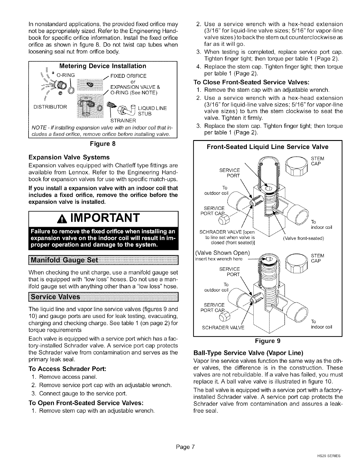
Innonstandardapplications,theprovidedfixedorificemay
notbeappropriatelysized.RefertotheEngineeringHand-
bookforspecificorificeinformation.Installthefixedorifice
orificeas shownin figure8. Donottwistcaptubeswhen
looseningsealnutfromorificebody.
Metering Device Installation
o O-RING ORIFICE
or
EXPANSION VALVE &
//
DISTRIBUTOR
STRAINER
NO TE -If installing expansion valve with an indoor coil that in-
cludes a fixed orifice, remove orifice before installing valve.
Figure 8
Expansion Valve Systems
Expansion valves equipped with Chatleff type fittings are
available from Lennox. Refer to the Engineering Hand-
book for expansion valves for use with specific match-ups.
If you install a expansion valve with an indoor coil that
includes a fixed orifice, remove the orifice before the
expansion valve is installed.
IMPORTANT
When checking the unit charge, use a manifold gauge set
that is equipped with "low loss" hoses. Do not use a man-
ifold gauge set with anything other than a "low loss" hose.
The liquid line and vapor line service valves (figures 9 and
10) and gauge ports are used for leak testing, evacuating,
charging and checking charge, See table 1 (on page 2) for
torque requirements
Each valve is equipped with a service port which has a fac-
tory-installed Schrader valve. A service port cap protects
the Schrader valve from contamination and serves as the
primary leak seal,
To Access Schrader Port:
1, Remove access panel,
2, Remove service port cap with an adjustable wrench.
3. Connect gauge to the service port.
To Open Front-Seated Service Valves:
1. Remove stem cap with an adjustable wrench.
2. Use a service wrench with a hex-head extension
(3/16" for liquid-line valve sizes; 5/16" for vapor-line
valve sizes)to back the stem out counterclockwise as
far as it will go.
3. When testing is completed, replace service port cap.
Tighten finger tight; then torque per table 1 (Page 2).
4. Replace the stem cap. Tighten finger tight; then torque
per table 1 (Page 2).
To Close Front-Seated Service Valves:
1. Remove the stem cap with an adjustable wrench.
2. Use a service wrench with a hex-head extension
(3/16" for liquid-line valve sizes; 5/16" for vapor-line
valve sizes) to turn the stem clockwise to seat the
valve. Tighten it firmly.
3. Replace the stem cap. Tighten finger tight; then torque
per table 1 (Page 2).
Front-Seated Liquid Line Service Valve
STEM
SERVICE _\ CAP
PORT
To
outdoor coil
SERVICE
PORT CAI
SCHRADER VALVE [oper
to line set when valve is
closed (front seated)]
(Valve Shown Open)
insert hex wrench here
SERVICE
PORT
To \
outdoor coil
indoor coil
(Valve front-seated)
STEM
CAP
SERVICE
PORT CAI
To
SCHRADER VALVE indoor coil
Figure 9
Bali-Type Service Valve (Vapor Line)
Vapor line service valves function the same way as the oth-
er valves, the difference is in the construction. These
valves are not rebuildable. If a valve has failed, you must
replace it. A ball valve valve is illustrated in figure 10.
The ball valve is equipped with a service port with a factory-
installed Schrader valve. A service port cap protects the
Schrader valve from contamination and assures a leak-
free seal.
Page 7
HS29 SERIES
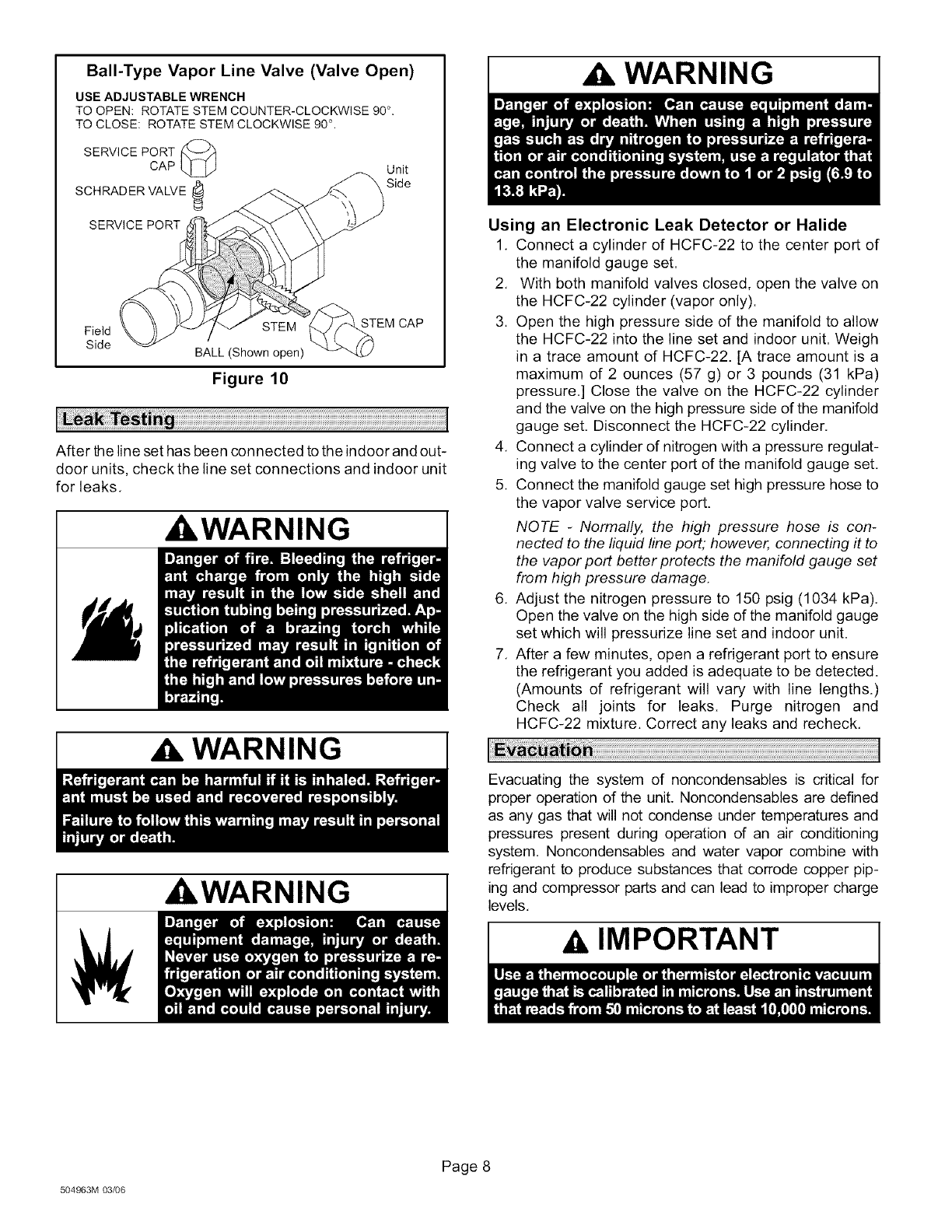
Bali-Type Vapor Line Valve (Valve Open)
USE ADJUSTABLE WRENCH
TO OPEN: ROTATE STEM COUNTER-CLOCKWISE 90 °.
TO CLOSE: ROTATE STEM CLOCKWISE 90 °.
SERVICE PORT _
CAP Unit
SCHRADER VALVE _ Side
SERVICE PORT
Field STEM
Side BALL (Shown open)
Figure 10
STEM CAP
After the line set has been connected to the indoor and out-
door units, check the line set connections and indoor unit
for leaks.
,WARNING I
WARNING
WARNING
I
I
WARNING
Using an Electronic Leak Detector or Halide
1. Connect a cylinder of HCFC-22 to the center port of
the manifold gauge set.
2. With both manifold valves closed, open the valve on
the HCFC-22 cylinder (vapor only).
3. Open the high pressure side of the manifold to allow
the HCFC-22 into the line set and indoor unit. Weigh
in a trace amount of HCFC-22. [A trace amount is a
maximum of 2 ounces (57 g) or 3 pounds (31 kPa)
pressure,] Close the valve on the HCFC-22 cylinder
and the valve on the high pressure side of the manifold
gauge set, Disconnect the HCFC-22 cylinder.
4. Connect a cylinder of nitrogen with a pressure regulat-
ing valve to the center port of the manifold gauge set,
5. Connect the manifold gauge set high pressure hose to
the vapor valve service port.
NOTE -Normally, the high pressure hose is con-
nected to the liquid line port; however, connecting it to
the vapor port better protects the manifold gauge set
from high pressure damage,
6. Adjust the nitrogen pressure to 150 psig (1034 kPa).
Open the valve on the high side of the manifold gauge
set which will pressurize line set and indoor unit.
7. After a few minutes, open a refrigerant port to ensure
the refrigerant you added is adequate to be detected.
(Amounts of refrigerant will vary with line lengths.)
Check all joints for leaks. Purge nitrogen and
HCFC-22 mixture. Correct any leaks and recheck.
Evacuating the system of noncondensables is critical for
proper operation of the unit. Noncondensables are defined
as any gas that will not condense under temperatures and
pressures present during operation of an air conditioning
system, Noncondensables and water vapor combine with
refrigerant to produce substances that corrode copper pip-
ing and compressor parts and can lead to improper charge
levels.
AIMPORTANT
504963M 03/06
Page 8
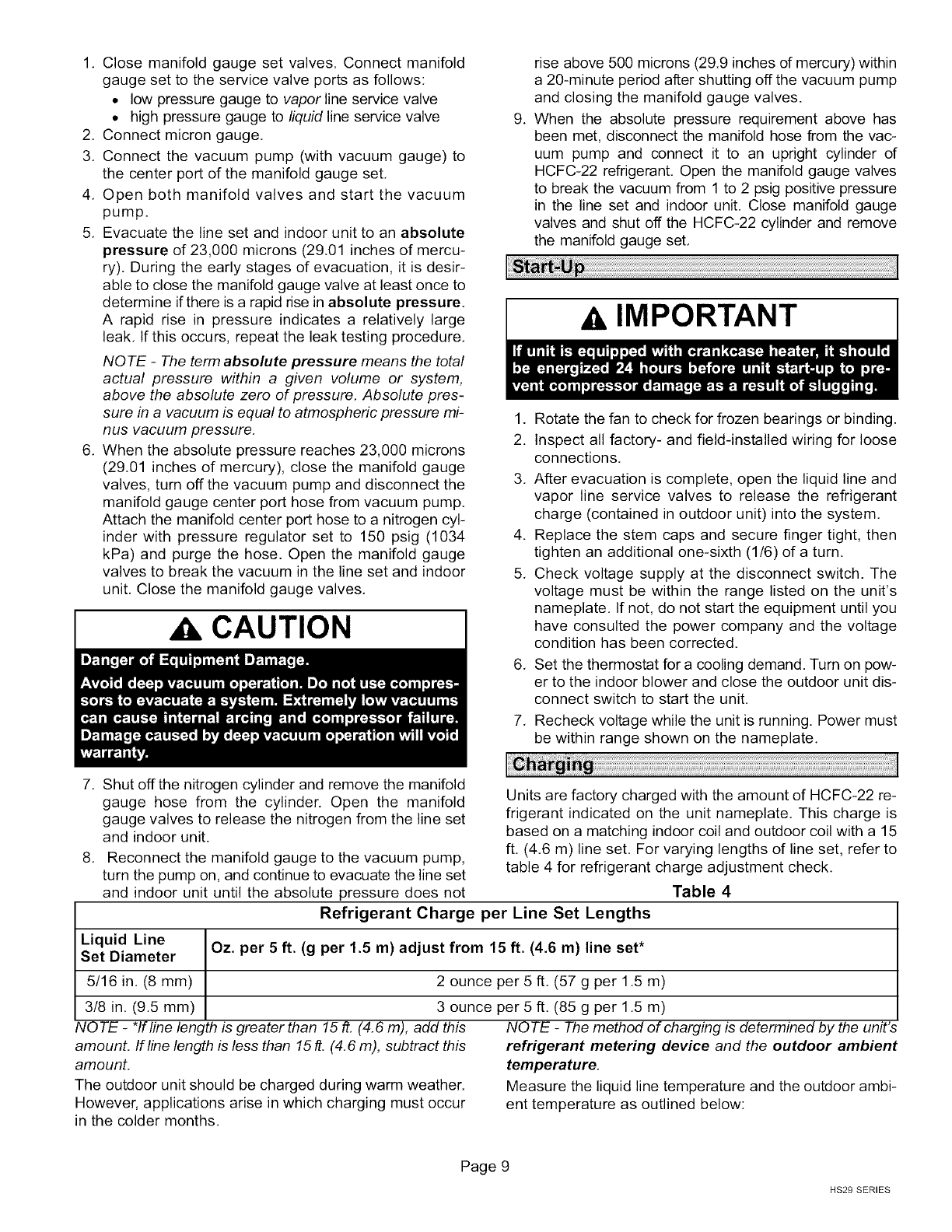
1. Closemanifoldgaugesetvalves.Connectmanifold
gaugesetto theservicevalveportsasfollows:
• lowpressuregaugeto vapor line service valve
• high pressure gauge to liquid line service valve
2. Connect micron gauge,
3. Connect the vacuum pump (with vacuum gauge) to
the center port of the manifold gauge set,
4. Open both manifold valves and start the vacuum
pump.
5. Evacuate the line set and indoor unit to an absolute
pressure of 23,000 microns (29.01 inches of mercu-
ry). During the early stages of evacuation, it is desir-
able to close the manifold gauge valve at least once to
determine if there is a rapid rise in absolute pressure,
A rapid rise in pressure indicates a relatively large
leak, If this occurs, repeat the leak testing procedure,
NOTE -The term absolute pressure means the total
actual pressure within a given volume or system,
above the absolute zero of pressure, Absolute pres-
sure in a vacuum is equal to atmospheric pressure mi-
nus vacuum pressure,
6. When the absolute pressure reaches 23,000 microns
(29.01 inches of mercury), close the manifold gauge
valves, turn off the vacuum pump and disconnect the
manifold gauge center port hose from vacuum pump.
Attach the manifold center port hose to a nitrogen cyl-
inder with pressure regulator set to 150 psig (1034
kPa) and purge the hose. Open the manifold gauge
valves to break the vacuum in the line set and indoor
unit, Close the manifold gauge valves.
CAUTION
.
rise above 500 microns (29.9 inches of mercury) within
a 20-minute period after shutting off the vacuum pump
and closing the manifold gauge valves.
When the absolute pressure requirement above has
been met, disconnect the manifold hose from the vac-
uum pump and connect it to an upright cylinder of
HCFC-22 refrigerant. Open the manifold gauge valves
to break the vacuum from 1 to 2 psig positive pressure
in the line set and indoor unit. Close manifold gauge
valves and shut off the HCFC-22 cylinder and remove
the manifold gauge set,
IMPORTANT
1. Rotate the fan to check for frozen bearings or binding.
2. Inspect all factory- and field-installed wiring for loose
connections.
3. After evacuation is complete, open the liquid line and
vapor line service valves to release the refrigerant
charge (contained in outdoor unit) into the system.
4. Replace the stem caps and secure finger tight, then
tighten an additional one-sixth (1/6) of a turn,
5. Check voltage supply at the disconnect switch. The
voltage must be within the range listed on the unit's
nameplate. If not, do not start the equipment until you
have consulted the power company and the voltage
condition has been corrected.
6. Set the thermostat for a cooling demand. Turn on pow-
er to the indoor blower and close the outdoor unit dis-
connect switch to start the unit,
7. Recheck voltage while the unit is running. Power must
be within range shown on the nameplate.
7. Shut off the nitrogen cylinder and remove the manifold
gauge hose from the cylinder. Open the manifold
gauge valves to release the nitrogen from the line set
and indoor unit.
8. Reconnect the manifold gauge to the vacuum pump,
turn the pump on, and continue to evacuate the line set
and indoor unit until the absolute pressure does not
Units are factory charged with the amount of HCFC-22 re-
frigerant indicated on the unit nameplate, This charge is
based on a matching indoor coil and outdoor coil with a 15
ft, (4.6 m) line set, For varying lengths of line set, refer to
table 4 for refrigerant charge adjustment check.
Table 4
Refrigerant Charge per Line Set Lengths
Liquid Line Oz. per 5 ft. (g per 1.5 m) adjust from 15 ft. (4.6 m) line set*
Set Diameter
5/16 in. (8 mm)
3/8 in. (9.5 mm)
NOTE - *If line length is greater than 15 ft, (4,6 m), add this
amount. If line length is less than 15 ft. (4.6 m), subtract this
amount,
The outdoor unit should be charged during warm weather.
However, applications arise in which charging must occur
in the colder months.
2 ounce per 5 ft, (57 g per 1.5 m)
3 ounce per 5 ft, (85 g per 1.5 m)
NOTE -The method of charging is determined by the unit's
refrigerant metering device and the outdoor ambient
temperature.
Measure the liquid line temperature and the outdoor ambi-
ent temperature as outlined below:
Page 9
HS29 SERIES
1, Close manifold gauge set valves. Connect the man- ° low pressure gauge to vapor valve service port
ifold gauge set to the service valves: • high pressure gauge to liquid valve service port
504963M 03/06
Page 10
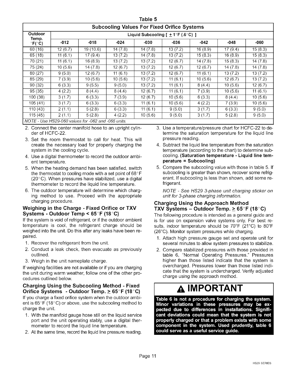
Table 5
Subcooling Values For Fixed Orifice Systems
Outdoor Liquid Subcooling [ + 1°F (.6°C) ]
Temp.
°F(°C) -012 -018 -024 -030 -036 -042 -048 -060
60 (16) 12 (6.7) 19 (10.6) 14 (7.8) 14 (7.8) 13 (7.2) 16 (8.9) 17 (9.4) 15 (8.3)
65 (18) 11(6.1) 17(9.4) 13(7.2) 14 (7.8) 13 (7.2) 15(8.3) 16 (8.9) 15 (8.3)
70 (21) 11(6.1) 16(8.9) 13(7.2) 13 (7.2) 12 (6.7) 14(7.8) 15 (8.3) 14 (7.8)
75 (24) 10 (5.6) 14(7.8) 12(6.7) 13 (7.2) 12 (6.7) 12(6.7) 14 (7.8) 14 (7.8)
80 (27) 9 (5.0) 12(6.7) 11(6.1) 13 (7.2) 12 (6.7) 11(6.1) 13 (7.2) 13 (7.2)
85 (29) 7 (3.9) 10(5.6) 10(5.6) 13 (7.2) 11(6.1) 10(5.6) 12 (6.7) 13 (7.2)
90 (32) 6 (3.3) 9 (5.5) 9 (5.0) 13 (7.2) 11(6.1) 8 (4.4) 10 (5.6) 12 (6.7)
95 (35) 4 (2.2) 8 (4.4) 8 (4.4) 12 (6.7) 11(6.1) 7 (3.9) 10 (5.6) 11 (6.1)
100 (38) 3 (1.7) 6 (3.3) 7 (3.9) 12 (6.7) 10 (5.6) 6 (3.3) 8 (4.4) 10 (5.6)
105 (41) 3 (1.7) 6 (3.3) 6 (3.3) 11 (6.1) 10 (5.6) 4 (2.2) 7 (3.9) 10 (5.6)
110(43) 2(1.1) 5(2.8) 6(3.3) 11 (6.1) 9(5.0) 3(1.7) 6(3.3) 9(5.0)
115 (45) 2 (1.1) 5 (2.8) 4 (2.2) 10 (5.6) 9 (5.0) 3 (1.7) 5 (2.8) 9 (5.0)
NOTE -Use HS29-060 values for -062 and -065 units.
2, Connect the center manifold hose to an upright cylin-
der of HCFC-22,
3, Set the room thermostat to call for heat. This will
create the necessary load for properly charging the
system in the cooling cycle,
4, Use a digital thermometer to record the outdoor ambi-
ent temperature.
5. When the heating demand has been satisfied, switch
the thermostat to cooling mode with a set point of 68 <_F
(20 <_C), When pressures have stabilized, use a digital
thermometer to record the liquid line temperature,
6. The outdoor temperature will determine which charg-
ing method to use, Proceed with the appropriate
charging procedure,
Weighing in the Charge - Fixed Orifice or TXV
Systems - Outdoor Temp < 65°F (18°C)
If the system is void of refrigerant, or if the outdoor ambient
temperature is cool, the refrigerant charge should be
weighed into the unit, Do this after any leaks have been re-
paired.
1, Recover the refrigerant from the unit,
2, Conduct a leak check, then evacuate as previously
outlined.
3, Weigh in the unit nameplate charge,
If weighing facilities are not available or if you are charging
the unit during warm weather, follow one of the other pro-
cedures outlined below,
3. Use a temperature/pressure chart for HCFC-22 to de-
termine the saturation temperature for the liquid line
pressure reading.
4. Subtract the liquid line temperature from the saturation
temperature (according to the chart) to determine sub-
cooling. (Saturation temperature - Liquid line tem-
perature =Subcooling)
5. Compare the subcooling value with those in table 5. If
subcooling is greater than shown, recover some refrig-
erant. If subcooling is less than shown, add some re-
frigerant.
NOTE -See HS29 3-phase unit charging sticker on
unit for 3-phase charging information.
Charging Using the Approach Method
TXV Systems - Outdoor Temp. _>65°F (18 °C)
The following procedure is intended as a general guide and
is for use on expansion valve systems only. For best re-
sults, indoor temperature should be 70°F (21°C) to 80°F
(26°C), Monitor system pressures while charging.
1, Attach high pressure gauge set and operate unit for
several minutes to allow system pressures to stabilize.
2, Compare stabilized pressures with those provided in
table 6, "Normal Operating Pressures." Pressures
higher than those listed indicate that the system is
overcharged. Pressures lower than those listed indi-
cate that the system is undercharged, Verify adjusted
charge using the approach method,
Charging Using the Subcooling Method -Fixed
Orifice Systems - Outdoor Temp. _>65°F (18°C)
If you charge a fixed orifice system when the outdoor ambi-
ent is 65_F (18<_C) or above, use the subcooling method to
charge the unit.
1, With the manifold gauge hose still on the liquid service
port and the unit operating stably, use a digital ther-
mometer to record the liquid line temperature,
2, At the same time, record the liquid line pressure reading,
AIMPORTANT
Page 11
HS29 SERIES

Table 6
Normal Operating Pressures In psig (liquid +/- 10 and vapor+/- 5 PSIG)*
Out. Coil HS29-012 HS29-018 HS29-024 HS29-030 HS29-036 HS29-042 HS29-048 HS29-060
Mode Entering Air
Temp.
°F (°C) Liq Suc Liq Suc Liq Suc Liq Suc Liq Suc Liq Suc Liq Suc Liq Suc
65 (18.3) 139 57 150 69 147 58 160 64 165 62 169 72 168 73 158 67
75 (23.9) 165 67 175 74 174 63 185 67 192 66 197 75 195 75 185 71
Fixed
Orifice 85 (29.4) 192 73 201 79 204 68 216 71 223 69 227 78 225 78 216 74
95 (35.0) 222 78 229 82 234 75 248 73 257 71 259 80 257 80 247 77
105 (40.6) 254 81 262 86 272 77 284 76 292 73 294 83 291 82 283 79
65 (18.3) 141 60 149 76 143 71 154 68 162 66 159 76 154 75 154 75
75 (23.9) 164 64 173 78 170 73 174 70 190 67 188 78 183 76 181 77
TXV 85 (29.4) 193 72 197 81 202 73 204 70 224 68 222 78 216 77 213 79
95 (35.0) 222 77 228 82 236 75 246 72 257 71 257 79 251 78 249 80
105 (40.6) 255 81 260 85 271 76 276 74 296 72 294 80 288 79 285 82
*These are typical pressures only. Indoor match up, indoor air quafity and indoor load will cause the pressures to vary
NOTE -Use HS29-060 values for-062 and -065 units.
3. Record outdoor ambient temperature using a digital
thermometer.
4. NOTE - See HS29 3-phase unit charging sticker on
unit for 3-phase charging information.
5. Use the same digital thermometer you used to check
the outdoor ambient temperature to check the liquid
line temperature.
6. The difference between the ambient and liquid tem-
peratures should match values given in table 7. If the
values don't agree with the those in table 7, add refrig-
erant to lower the approach temperature, or recover
refrigerant from the system to increase the approach
temperature.
NOTE -See HS29 3-phase unit charging sticker on
unit for 3-phase charging information.
Table 7
Compressor Start Kit
The -012, -018, and -024 single phase units have internal
start components and do not require field installation of a
compressor start kit.
High and Low Pressure Switches (international
units and units with factory-installed options)
International units and units with factory-equipped options
include high and low pressure switches. The pressure
switches are located on valve cores in the liquid line to al-
low for easy access. The manually reset high pressure
switch protects the system from high pressure conditions
as a result of a fan failure or a blocked or dirty coil. The low
pressure switch (SPST, NO) protects the system com-
pressor from damage due to a loss of charge. The low
pressure switch trips at 15 + 5 psig (103 + 34 kPa) and au-
tomatically resets at 25 + 3 psig (172 + 21 kPa).
Approach Values
HS29
Model -012 -018 -024 -030 -036 -042 -048 -060
Temp. 6 8 11 11 14 18 17 12
°F(°C) (3.3) (4.4) (6.1) (6.1) (7.8) (10) (9.4) (6.7)
Liquid Line Temperature °F (°C)
Outdoor Ambient Temperature ° F ( ° C)
Approach Value °F (°C)
Maintenance and service must be performed by a qualified
installer or service agency.
NOTE -Use HS29-060 values for-062 and -065 units.
Checking the Charge Using Normal Operating
Pressures
Use table 6 as a general guide for performing maintenance
checks.
504963M 03/06
Page 12
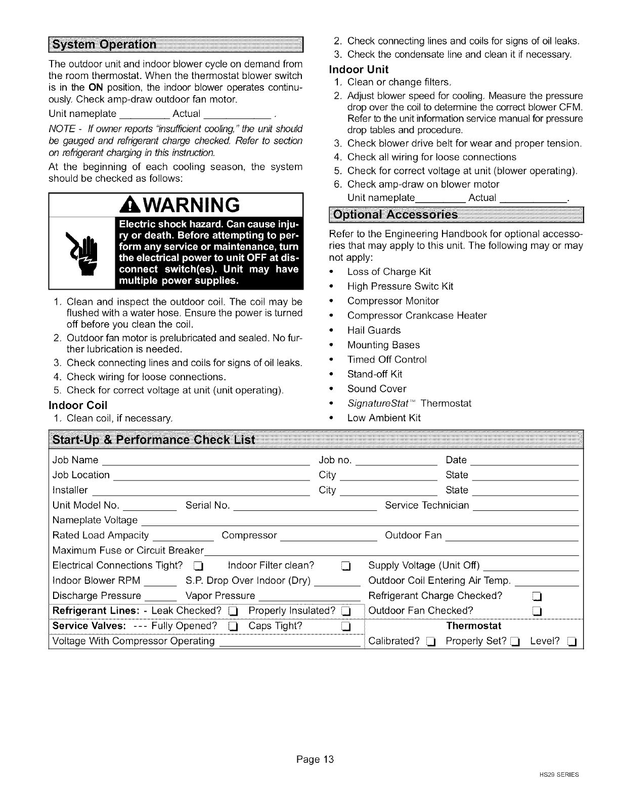
Theoutdoorunitandindoorblowercycleondemandfrom
theroomthermostat.Whenthethermostatblowerswitch
is intheONposition,theindoorbloweroperatescontinu-
ously.Checkamp-drawoutdoorfanmotor.
Unitnameplate Actual
NOTE -If owner reports "insufficient cooling," the unit should
be gauged and refrigerant charge checked, Refer to section
on refrigerant charging in this instruction,
At the beginning of each cooling season, the system
should be checked as follows:
, WARNING
1, Clean and inspect the outdoor coil. The coil may be
flushed with a water hose, Ensure the power is turned
off before you clean the coil,
2, Outdoor fan motor is prelubricated and sealed, No fur-
ther lubrication is needed,
3, Check connecting lines and coils for signs of oil leaks,
4. Check wiring for loose connections.
5. Check for correct voltage at unit (unit operating),
Indoor Coil
1, Clean coil, if necessary,
2. Check connecting lines and coils for signs of oil leaks,
3. Check the condensate line and clean it if necessary,
Indoor Unit
1, Clean or change filters,
2, Adjust blower speed for cooling, Measure the pressure
drop over the coil to determine the correct blower CFM
Refer to the unit information service manual for pressure
drop tables and procedure,
3. Check blower drive belt for wear and proper tension.
4. Check all wiring for loose connections
5, Check for correct voltage at unit (blower operating).
6, Check amp-draw on blower motor
Unit nameplate Actual
Refer to the Engineering Handbook for optional accesso-
ries that may apply to this unit, The following may or may
not apply:
• Loss of Charge Kit
• High Pressure Switc Kit
• Compressor Monitor
• Compressor Crankcase Heater
• Hail Guards
• Mounting Bases
• Timed Off Control
• Stand-off Kit
• Sound Cover
•SignatureStat'" Thermostat
• Low Ambient Kit
Job Name Job no.
Job Location City
Installer City
Unit Model No, Serial No,
Nameplate Voltage
Rated Load Ampacity Compressor
Maximum Fuse or Circuit Breaker
Electrical Connections Tight? _1 Indoor Filter clean?
Indoor Blower RPM S,R Drop Over Indoor (Dry)
Discharge Pressure __ Vapor Pressure
Refrigerant Lines: - Leak Checked? Properly Insulated?
Date
State
State
Service Technician
Outdoor Fan
Supply Voltage (Unit Off)
Outdoor Coil Entering Air Temp.
Refrigerant Charge Checked?
Outdoor Fan Checked?
Service Valves: --- Fully Opened? _ Caps Tight? _ Thermostat
Voltage With Compressor Operating Calibrated? _ Properly Set? _ Level?
Page 13
HS29 SERIES

