LENNOX Air Conditioner/heat Pump(outside Unit) Manual L0805508
User Manual: LENNOX LENNOX Air conditioner/heat pump(outside unit) Manual LENNOX Air conditioner/heat pump(outside unit) Owner's Manual, LENNOX Air conditioner/heat pump(outside unit) installation guides
Open the PDF directly: View PDF ![]() .
.
Page Count: 4
_2006 Lennox Industries Inc.
Dallas, Texas, USA
COOLING UNITS
KITS AND ACCESSORIES
505,054M
11/06
Supersedes 02/06
)puTech n[cal
bHcations
Litho U.S.A.
CONDENSER COIL
REPLACEMENT KIT
INSTALLATION INSTRUCTIONS FOR REPLACING CONDENSER COIL
IN XC21, XC14, XC13, & AC13 SERIES UNITS
Shipping and Packing List ...................... 1
Requirements ................................. 1
Installing Coils:
Coil Page
XC21-024 through -048
XC14-018, -024 2
XC13-018 through -048
AC13-018 through -042
XC21-060
XC14-030 through -060
XC 13-060 3
AC13-048 and -060
A, IMPORTANT
Package 1 of 1 contains:
• Condenser coil (qty 1)
• Bag assembly (qty 1) including:
1 - Discharge line with elbow
1 - 1/2" Coupling
1 - Kit Installation Instructions (this manual)
Check the replacement coil for shipping damage. If you
find any damage, immediately contact the last carrier.
Verify that the coil has holding charge. Remove the cap
from the discharge stub and press the valve core. The coil
should have approximately 10 psi dry air holding charge. If
there is no charge, repressurize the coil and check for
leaks.
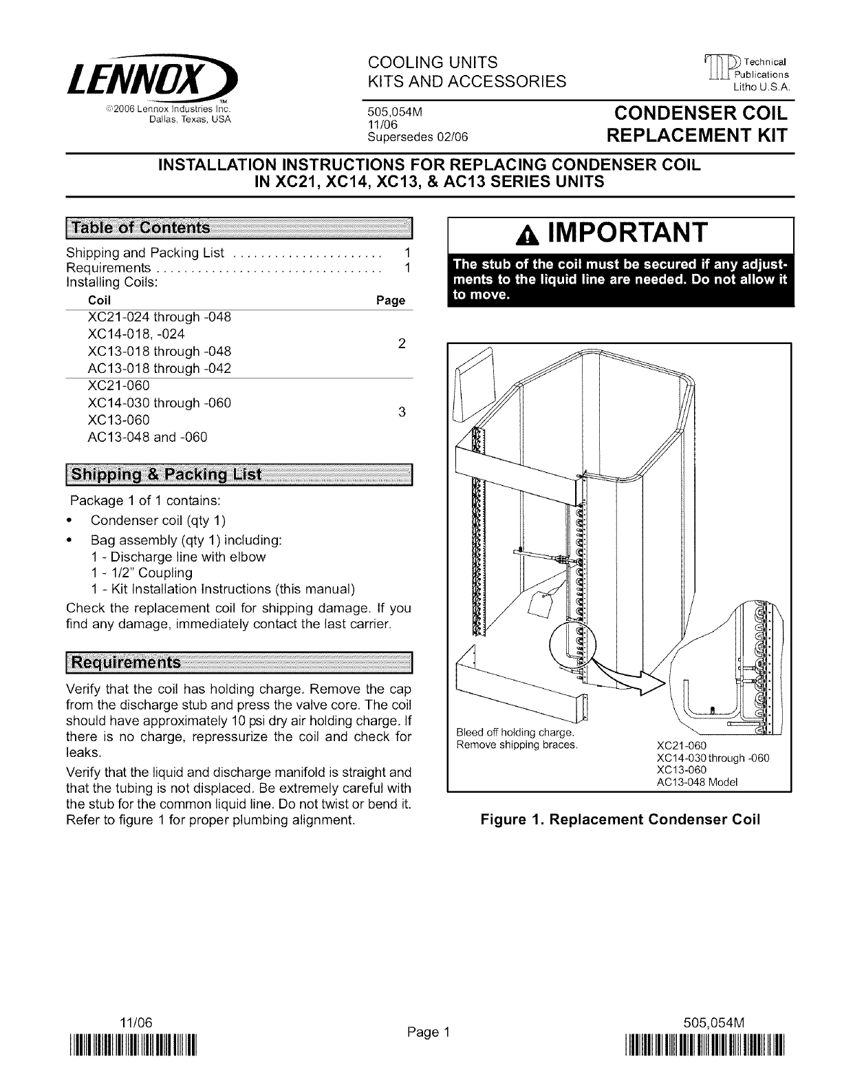
Verify that the liquid and discharge manifold is straight and
that the tubing is not displaced. Be extremely careful with
the stub for the common liquid line. Do not twist or bend it.
Refer to figure 1 for proper plumbing alignment.
Bleed off holding charge,
Remove shipping braces. XC21-060
XC14-030 through -060
XC13-060
AC13-048 Model
Figure 1. Replacement Condenser Coil
11/06
IIIIIII]IIIIIIIIIHIIIHIHIHIIIIIIll Page 1 505,054M
IIIIIIIIIIIIIIIHIIIIII]IIIIIIIII]IHIIIIIHIIIIII

Installing Coils: XC21-024 thru -048, XC14-018 thru
-060, XC13-018 thru -048, AC13-018 thru -042
1, Disconnect all power to the unit.
2. Reclaim the refrigerant from the unit,
3. Remove access panel, side (Iouvered) panels, top
panel, and corner posts. Remove the screws that at-
tach the coil endplate to the control box and compres-
sor enclosure, Keep the screws,
4. Unscrew the liquid service and suction valve brackets
from the coil, Sweat off the liquid line at the swaged
joint next to the coil outlet,
5. Use a tubing cutter to cut the discharge line approxi-
mately one inch from the manifold on the end of the
discharge line. See figure 2.
XC21 MANIFOLD
Cut Here
I
Figure 2. Existing Discharge Line
6. Remove the existing coil,
7, Install the replacement coil assembly.
8. Remove the holding charge by depressing the valve
core. Use a tubing cutter to cut off the discharge stub
approximately one inch from the manifold, (This will
also remove the pressure tap.) See figure 3.
PRESSURE TAP (VALVE CORE)
Figure 3. Replacement Coil Discharge Line
9. Align the discharge stub on the replacement coil with
the discharge line from the compressor, Install the pro-
vided coupling between the two tubes. Sweat the cou-
pling into place. See figure 4.
DISCHARGE f_-il I I I M[_ANIFOLD
LINE ._..._U__ [/ COUPLING
Figure 4. Replacement Discharge Line and
Coupling
10. Sweat in the liquid line, Reattach the liquid and suction
service valves,
11. Replace the screws that attach the coil endplate to the
control box and compressor enclosure.
12. Replace the corner posts, side (Iouvered) panels, and
top panel,
13. Refer to the unit installation instructions for leak test-
ing, evacuation, and start-up procedures. Charge the
unit as outlined in the installation instructions or ac-
cording to the charging sticker,
14. Once you have installed the replacement coil, start the
compressor and observe the discharge line, Verify that
there is minimal vibration between the shock loop and
the manifold on the outdoor coil's discharge line.
15. If there is visible motion, apply weight kit number
38K46 to the discharge line. Install the weight kit on the
horizontal run after the shock loop, or other suitable
area to achieve acceptable results. Rotate the weight
kit on the tubing to change vibration characteristics,
NOTE -Visible motion could result in a future failure of
the replacement coil,
16. Replace access panel.
Page 2

BARREL
MANIFOLD
DISCHARGE LINE
Figure 5. Existing Discharge Line -XC21-060
NOTE- Measure re-
placement coil dis-
charge line. Cut exist-
ing discharge line on
unit to allow proper fit
up to new replacement
coil. BARREL
MANIFOLD
DISCHARGE
LINE
Figure 6. Existing Discharge Line -
xc14-o3o thru -060
BARREL
MANIFOLD
DISCHARGE
LINE
Figure 7. Existing Discharge Line -
XC13-060, AC13-048 & -060
11,
12,
Page 3
Installing Coils: XC21-060, XC14-030 thru -060,
XC13-060, AC13-048 & -060
1, Disconnect all power to the unit.
2. Reclaim the refrigerant from the unit,
3, Remove access panel, side (Iouvered) panels, top
panel, and corner posts. Remove the screws that at-
tach the coil endplate to the control box and compres-
sor enclosure, Keep the screws,
4, Unscrew the liquid service and suction valve brackets
from the coil, Sweat off the liquid line at the swaged
joint to the coil outlet.
5, Perform the appropriate model-dependent step:
XC21-060 - Use a tubing cutter to cut the discharge
line approximately two inches from the barrel manifold
on the end of the discharge line, See figure 5,
XC14-030 thru -060, XC13-060, AC13-048,
AC13-060--Use a tubing cutter to cut the discharge
line approximately two inches from the bend nearest
the compressor, See figure 6 (XC14) or 7 (XC13),
6, Remove the existing coil and discharge line,
7, Install the replacement coil assembly.
8, Perform the appropriate model-dependent step:
XC21-060 - Remove holding charge by depressing the
valve core, Use a tubing cutter to cut off the discharge
stub approximately 2 inches from the barrel manifold,
This will also remove the pressure tap (see figure 8),
BARREL MANIFOLD IT_J j[_,,
DISCHARGE LINE _ H 2
e___ut Here
Figure 8. Replacement Coil Discharge Line -
XC21-060
XC-14-030 thru -060, XC13-060, AC13-048 & -060 -
Remove holding charge by depressing the valve core.
Use a tubing cutter to cut off discharge stub approxi-
mately 2 inches from the bend closest to the stub end
(see figure 9),
BARREL MANIFOLDII "_.,_._C ut I
DISCHARGE LINE_ I 2" Here
Figure 9. Replacement Coil Discharge Line -
XC14-030 thru -060, XC13-060, AC13-048 & -060
9, Align discharge stub on replacement coil with dis-
charge line from compressor. Install provided coupling
between the two tubes, Sweat coupling into place,
10. Sweat in the liquid line, Reattach the liquid and suction
service valves.
Replace the screws that attach the coil endplate to the
control box and compressor enclosure.
Replace corner posts, side (Iouvered) panels, and top
panel.
13,Refertotheunitinstallationinstructionsforleaktest-
ing,evacuation,andstart-upprocedures.Chargethe
unitasoutlinedintheinstallationinstructionsor ac-
cordingtothechargingsticker,
14,Onceyouhaveinstalledthereplacementcoil,startthe
compressorandobservethedischargeline.Verifythat
thereisminimalvibrationbetweentheshockloopand
themanifoldontheoutdoorcoil'sdischargeline,
15,If thereis visiblemotion,applyweightkit number
38K46tothedischargeline.Installtheweightkitonthe
horizontalrunaftertheshockloop,or othersuitable
areatoachieveacceptableresults.Rotatetheweight
kitonthetubingtochangevibrationcharacteristics,
NOTE -Visible motion could result in a future failure of
the replacement coil.
16, Replace access panel,
Page 4
