LENNOX Furnace/Heater, Gas Manual L0806183
User Manual: LENNOX LENNOX Furnace/Heater, Gas Manual LENNOX Furnace/Heater, Gas Owner's Manual, LENNOX Furnace/Heater, Gas installation guides
Open the PDF directly: View PDF ![]() .
.
Page Count: 48
E Wvm)
®
,t,: 2005 Lennox industries inc.
Dallas, Texas, USA
RETAIN THESE INSTRUCTIONS
FOR FUTURE REFERENCE
INSTALLATION
INSTRUCTIONS
G51MP SERIES UNITS
GASU.iTS qT_bbTeoho,ca,
505,065M _L_ Publications
07/07
Supersedes 07/2005 Lithe U.S.A.
Unit Dimensions ............................... 2
G51MP Parts Identification ...................... 3
Shipping and Packing List ....................... 4
Safety Information .............................. 4
General ....................................... 6
Combustion, Dilution & Ventilation Air ............. 6
Installation - Setting Equipment .................. 8
Filters ........................................ 16
Duct System .................................. 16
Pipe & Fittings Specifications ................... 16
Vent Piping Guidelines ......................... 18
Joint Cementing Procedure ..................... 19
Venting Practices ............................. 19
Gas Piping ................................... 30
Electrical ..................................... 33
Unit Start-Up ................................. 37
Gas Pressure Adjustment ...................... 38
High Altitude Information ....................... 39
Other Unit Adjustments ........................ 40
Service ...................................... 41
Repair Parts List .............................. 43
Ignition Control Board Diagnostic Codes ......... 43
Troubleshooting ............................... 44
Vent Pipe Sizing Worksheet .................... 48
Start-Up & Performance Check List .............. 48
AWARNING
Do not store or use gasoline or other
flammable vapors and liquids in the
vicinity of this or any other ap-
pliance.
Installation and service must be
performed by a qualified installer,
service agency or the gas supplier.
WHAT TO DO IF YOU SMELL GAS:
•Do not try to light any appliance.
•Do not touch any electrical switch; do not
use any phone in your building.
•Leave the building immediately.
•Immediately call your gas supplier from a
neighbor's phone. Follow the gas supplier's
instructions.
•If you cannot reach your gas supplier, call
the fire department.
07/07
IIIlllllllllllllllllllllllllllllllllllll Page 1
505,065M
IIIIIIIIIIIIIIIIIIIIIIIIIIIIIIIIIIIIIBlllllllll
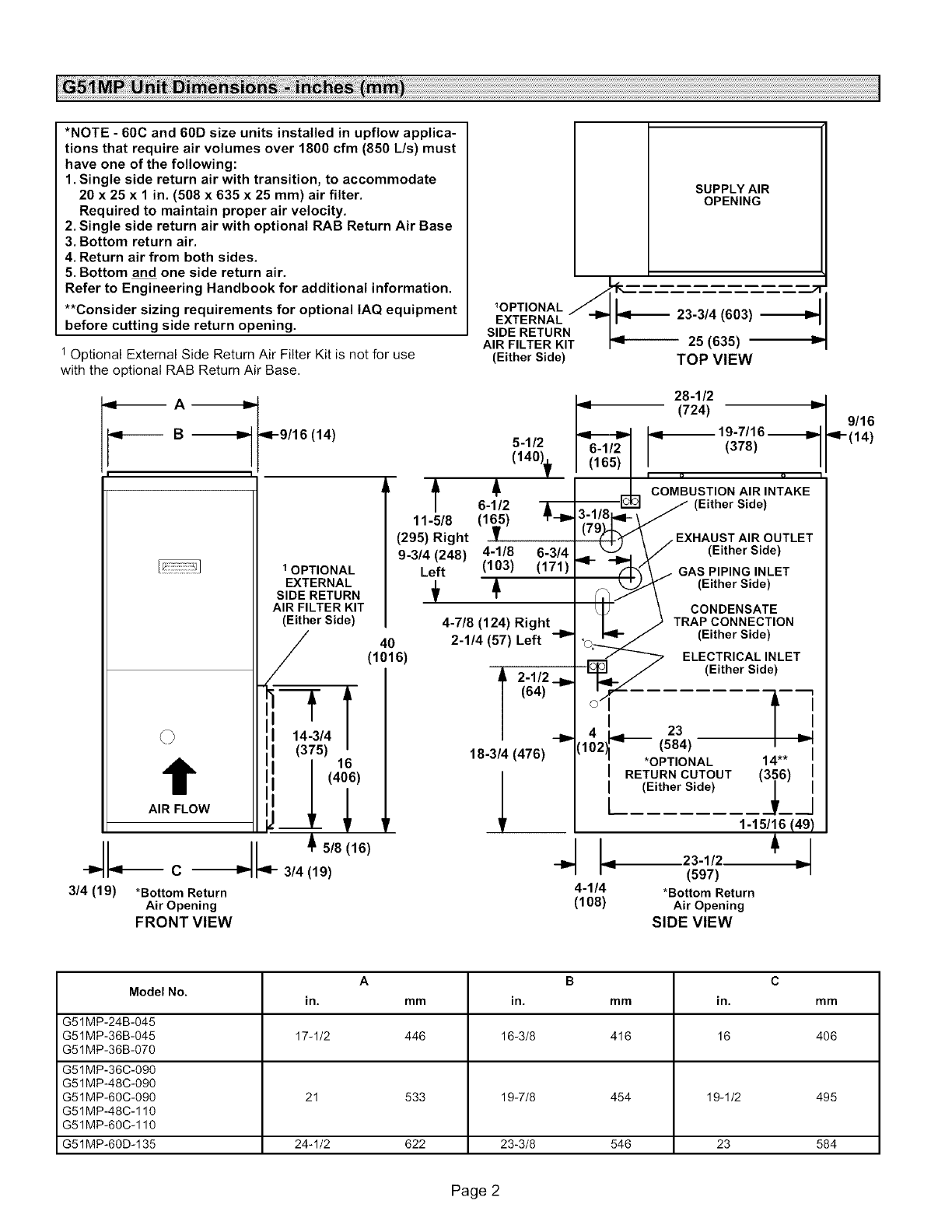
*NOTE - 60C and 60D size units installed in upflow applica-
tions that require air volumes over 1800 cfm (850 L/s) must
have one of the following:
1. Single side return air with transition, to accommodate
20 x 25 x 1 in. (508 x 635 x 25 mm) air filter.
Required to maintain proper air velocity.
2. Single side return air with optional RAB Return Air Base
3. Bottom return air.
4. Return air from both sides.
5. Bottom and one side return air.
Refer to Engineering Handbook for additional information.
**Consider sizing requirements for optional IAQ equipment
before cutting side return opening.
1 Optional External Side Return Air Filter Kit is not for use
with the optional RAB Return Air Base.
SUPPLY AIR
OPENING
_OPTIONAL /=_-
EXTERNAL 23-3/4 (803)
SIDE RETURN I.........
AIR FILTER KIT I_ za _o._a/ v
(Either Side) TOP VIEW
._ A -_
9v----- B -_
t
AIR FLOW
9-9/16 (14)
1OPTIONAL
EXTERNAL
SIDE RETURN
AIR FILTER KIT
(Either Side)
5/8(16)
314(19)
t
11-5/8
(295) Right
9-3/4 (248)
Left
40
(1016)
I_ 28 -1/2
I_ (724)
5-1/2 _._ _._1._ 19-7/16 ._1_
$r_ COMBUSTION AIR INTAKE
6-1/2 .... _ _ (Either Side)
( I )/ \ /EXHAUST AIR OUTLET
4-1/8 6-3/4 9- _/_ ._ (Either Side)
(103) (171) .. GASPIPINGINLET
_ll_._f\_._)_ (Either Side)
tJ \ .r_ CONDENSATE
L_TRAPCONNECTION
°Oo--___" (Either Side)
_ ELECTRICAL INLET
_p_.ql__ - (Either side )
04- --
I 23
{102 (584) I
"*OPTIONAL 14"*
I RETURN CUTOUT (356)
I (Either Side)
1-15/16 (49)
4-7/8 (124) Right
2-1/4 (57) Left -I_
A2-1/2 .__
(64)
18-3/4 (476)
Jl.--c 4-
3/4 (19) *Bottom Return 4-1/4 *Bottom Return
Air Opening (108) Air Opening
FRONT VIEW SIDE VIEW
9/16
'q'- (14)
A B C
Model No. in. mm in. mm in. mm
G51MP-24B-045
G51MP-36B-045 17-1/2 446 16-3/8 416 16 406
G51MP-36B-070
G51 MP-36C-090
G51MP-48C-090
G51MP-60C-090 21 533 19-7/8 454 19-1/2 495
G51MP-48C-110
G51MP-60C-110
G51MP-60D-135 24-1/2 622 23-3/8 546 23 584
Page 2
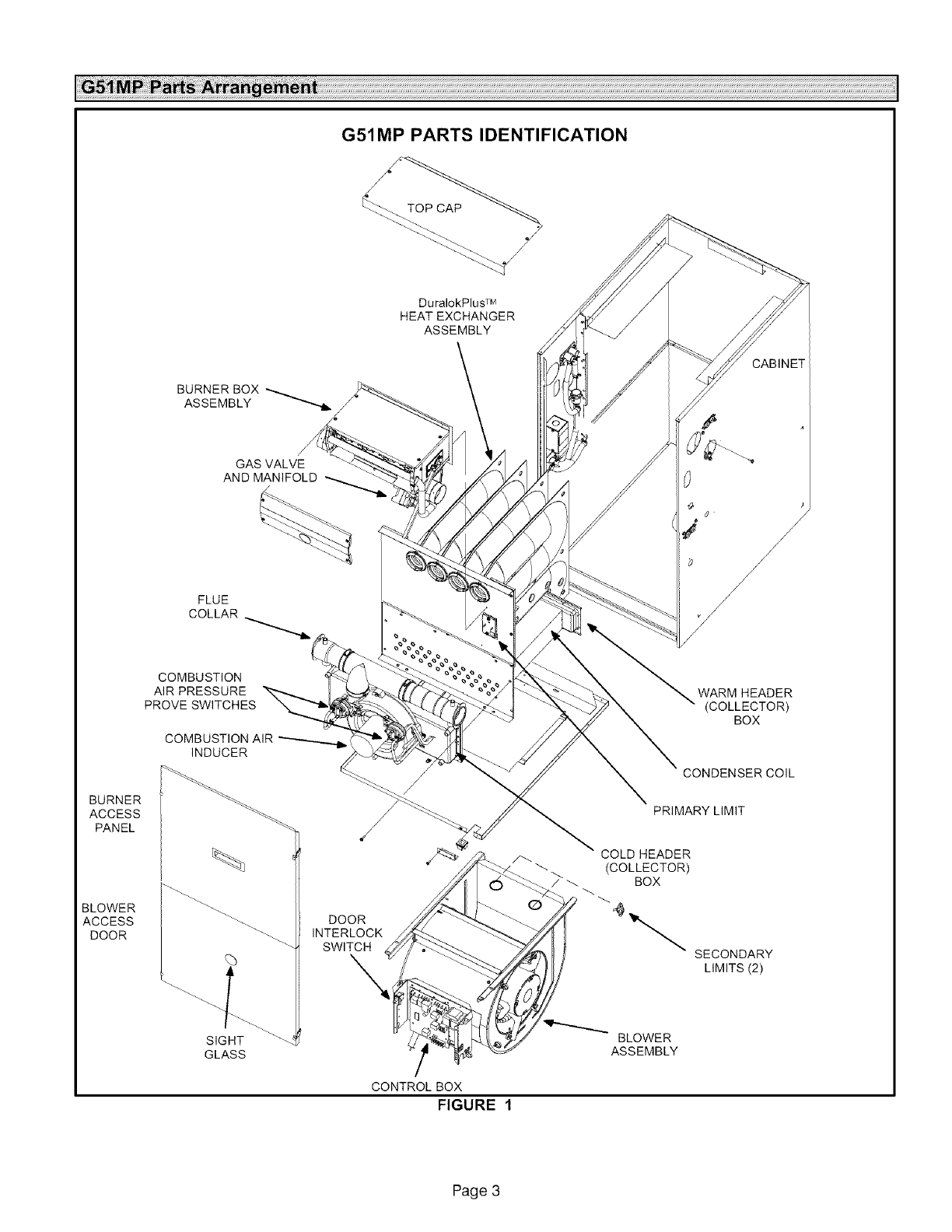
G51MP PARTS IDENTIFICATION
DuralokPlus TM
HEATEXCHANGER
ASSEMBLY
GAS VALVE
AND MANIFOLD
FLUE
COLLAR
COMBUSTION
AIR PRESSURE
PROVE SWITCHES
BURNER
ACCESS
PANEL
BLOWER
ACCESS
DOOR
%
SIGHT
GLASS
DOOR
INTERLOCK
SWITCH
\
CONTROL BOX
FIGURE 1
CABINET
WARM HEADER
(COLLECTOR)
BOX
CONDENSER COIL
PRIMARY LIMIT
,/_ COLD HEADER
(COLLECTOR)
/_ BOX
SECONDARY
LIMITS (2)
BLOWER
ASSEMBLY
Page 3
TheG51MPgasfurnaceisshippedreadyforinstallationin
theupflow,downflow,horizontalleftairdischargeorhori-
zontalrightairdischargeposition.Thefurnaceisshipped
withthebottompanelinplace.Thebottompanelmustbe
removedif theunitistobeinstalledinupflowapplications
withbottomreturnair.Thebottompanelmustalsobere-
movedanddiscardedinalldownfloworhorizontalapplica-
tions.
Thefurnaceisequippedforinstallationinnaturalgasap-
plications.A conversionkit(orderedseparately)isrequired
foruseinpropane/LPgasapplications.
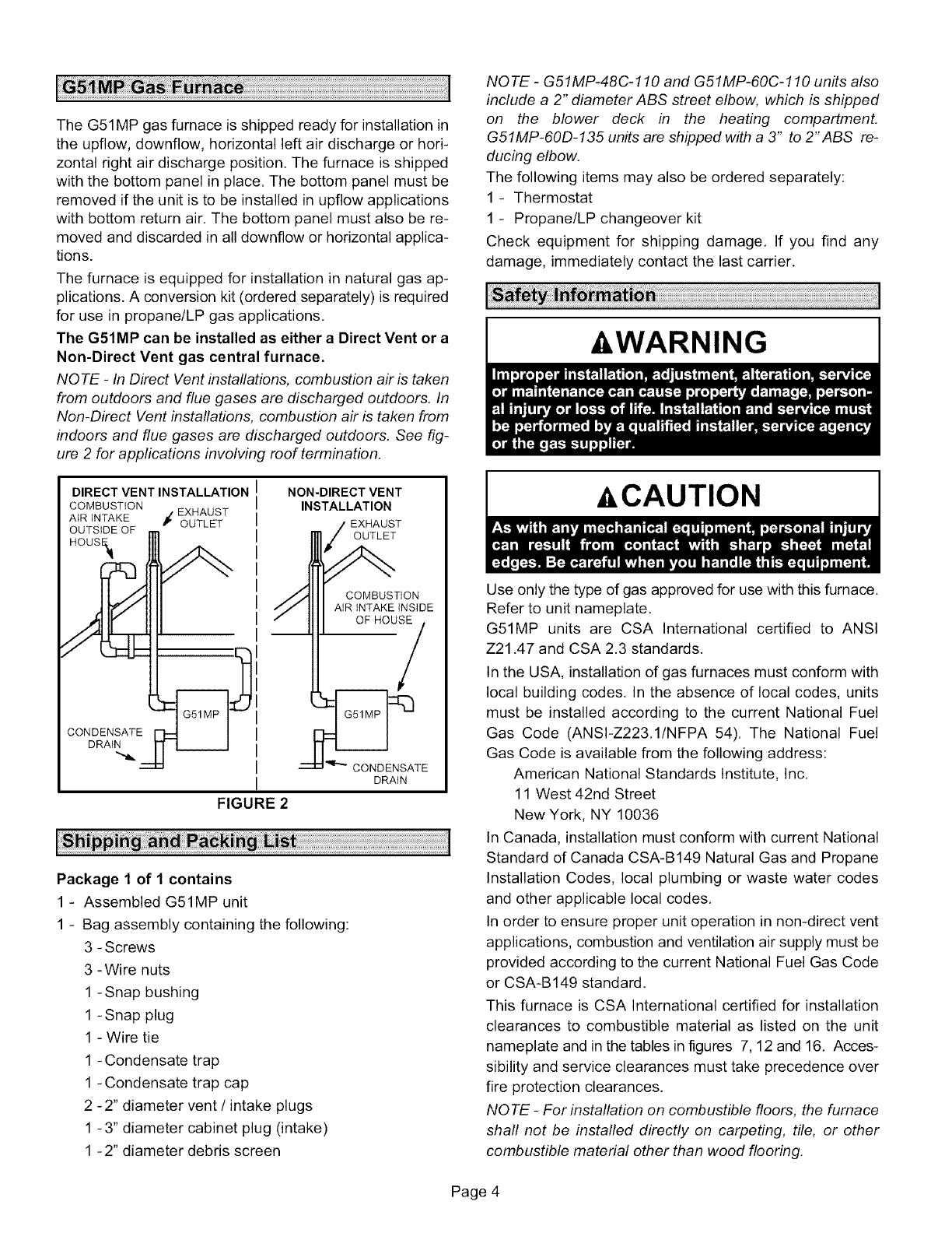
The G51MP can be installed as either a Direct Vent or a
Non-Direct Vent gas central furnace.
NOTE -In Direct Vent installations, combustion air is taken
from outdoors and flue gases are discharged outdoors. In
Non-Direct Vent installations, combustion air is taken from
indoors and flue gases are discharged outdoors. See fig-
ure 2for applications involving roof termination.
NOTE -G51MP-48C-110 and G51MP-60C-110 units also
include a 2" diameter ABS street elbow, which is shipped
on the blower deck in the heating compartment.
G51MP-60D-135 units are shipped with a 3" to 2"ABS re-
ducing elbow.
The following items may also be ordered separately:
1- Thermostat
1 - Propane/LP changeover kit
Check equipment for shipping damage. If you find any
damage, immediately contact the last carrier.
&WARNING
DIRECT VENT INSTALLATION
COMBUSTION I EXHAUST
AIR iNTAKE r OUTLET
OUTSIDE OF
HOUS_
DRAIN
NON-DIRECT VENT
INSTALLATION
'EXHAUST
OUTLET
COMBUSTION
AiR iNTAKE INSIDE
OF HOUSE
FIGURE 2
CONDENSATE
DRAIN
Package 1 of 1 contains
1 - Assembled G51MP unit
1 - Bag assembly containing the following:
3 - Screws
3 -Wire nuts
1 - Snap bushing
1 - Snap plug
1 - Wire tie
1 - Condensate trap
1 - Condensate trap cap
2 -2" diameter vent /intake plugs
1 - 3" diameter cabinet plug (intake)
1 -2" diameter debris screen
&CAUTION
Use only the type of gas approved for use with this furnace.
Refer to unit nameplate.
G51MP units are CSA International certified to ANSI
Z21.47 and CSA 2.3 standards.
In the USA, installation of gas furnaces must conform with
local building codes. In the absence of local codes, units
must be installed according to the current National Fuel
Gas Code (ANSl-Z223.1/NFPA 54). The National Fuel
Gas Code is available from the following address:
American National Standards Institute, Inc.
11 West 42nd Street
New York, NY 10036
In Canada, installation must conform with current National
Standard of Canada CSA-B149 Natural Gas and Propane
Installation Codes, local plumbing or waste water codes
and other applicable local codes.
In order to ensure proper unit operation in non-direct vent
applications, combustion and ventilation air supply must be
provided according to the current National Fuel Gas Code
or CSA-B149 standard.
This furnace is CSA International certified for installation
clearances to combustible material as listed on the unit
nameplate and in the tables in figures 7, 12 and 16. Acces-
sibility and service clearances must take precedence over
fire protection clearances.
NOTE -For installation on combustible floors, the furnace
shall not be installed directly on carpeting, tile, or other
combustible material other than wood flooring.
Page 4

Forinstallationinaresidentialgarage,thefurnacemustbe
installedsothattheburner(s)andtheignitionsourceare
locatednolessthan18inches(457mm)abovethefloor.
Thefurnacemustbelocatedorprotectedtoavoidphysical
damagebyvehicles.Whenafurnaceisinstalledinapublic
garage,hangar,orotherbuildingthathasahazardousat-
mosphere,thefurnacemustbeinstalledaccordingtorec-
ommendedgoodpracticerequirementsandcurrentNa-
tionalFuelGasCodeorCSAB149standards.
NOTE -Furnace must be adjusted to obtain a temperature
rise within the range specified on the unit nameplate. Fail-
ure to do so may cause erratic limit operation and prema-
ture heat exchanger failure.
This G51MP furnace may be used as a high-static unit
heater. The G51MP may also be installed in an aircraft
hangar in accordance with the Standard for Aircraft Han-
gars (ANSI/NFPA No. 408-1990).
Installation in parking structures must be in accordance
with the Standard for Parking Structures (ANSI/NFPA No.
88A-1991 ). Installation in repair garages must be in accor-
dance with the Standard for Repair Garages (ANSI/NFPA
No. 88B-1991 ).
This G51MP furnace must be installed so that its electrical
components are protected from water.
When this furnace is used with cooling units, it shall be
installed in parallel with, or on the upstream side of, cooling
units to avoid condensation in the heating compartment.
With a parallel flow arrangement, a damper (or other
means to control the flow of air) must adequately prevent
chilled air from entering the furnace. If the damper is manu-
ally operated, it must be equipped to prevent operation of
either the heating or the cooling unit, unless it is in the full
HEAT or COOL setting.
When installed, this furnace must be electrically grounded
according to local codes. In addition, in the United States,
installation must conform with the current National Electric
Code, ANSI/NFPA No. 70. The National Electric Code
(ANSl/NFPA No. 70) is available from the following ad-
dress:
National Fire Protection Association
1 Battery March Park
Quincy, MA 02269
In Canada, all electrical wiring and grounding for the unit
must be installed according to the current regulations of the
Canadian Electrical Code Part I (CSA Standard C22.1)
and/or local codes.
NOTE -This furnace is designed for a minimum continuous
return air temperature of 60°F (16°C) or an intermittent op-
eration down to 55°F (13°C) dry bulb for cases where a
night setback thermostat is used. Return air temperature
must not exceed 85°F (29°C) dry bulb.
The G51MP furnace may be installed in alcoves, closets,
attics, basements, garages, and utility rooms.
This furnace design has not been CSA certified for installa-
tion in mobile homes, recreational vehicles, or outdoors.
Never use an open flame to test for gas leaks. Check all
connections using a commercially available soap solution
made specifically for leak detection.
Lennox does not recommend the use of G51MP units as a
construction heater during any phase of construction. Very
low return air temperatures, harmful vapors and operation
of the unit with clogged or misplaced filters will damage the
unit.
G51MP units may be used for heating of buildings or struc-
tures under construction, if the following conditions are
met:
•The vent system must be permanently installed per
these installation instructions.
• A room thermostat must control the furnace. The use of
fixed jumpers that will provide continuous heating is not
allowed.
• The return air duct must be provided and sealed to the
furnace.
• Return air temperature range between 60°F (16°C) and
80°F (27°C) must be maintained.
• Air filters must be installed in the system and must be
maintained during construction.
• Air filters must be replaced upon construction comple-
tion.
• The inputrate and temperature rise mustbe setperthe
furnace rating plate.
• One hundred percent (100%) outdoor air must be pro-
vided for combustion air requirements during construc-
tion. Temporary ducting may supply outdoor air to the
furnace. Do not connect duct directly to the furnace.
Size the temporary duct following these instructions in
section for Combustion, Dilution and Ventilation Air in a
confined space with air from outside.
• The furnace heat exchanger, components, duct sys-
tem, air filters and evaporator coils must be thoroughly
cleaned following final construction clean-up.
• All furnace operating conditions (including ignition, in-
put rate, temperature rise and venting) must be verified
according to these installation instructions.
NOTE -The Commonwealth of Massachusetts stipu-
lates these additional requirements:
•Gas furnaces shall be installed by a licensedplumb-
er or gas fitter only.
•The gas cock must be "T handle" type.
•When a furnace is installed in an attic, the passage-
way to and service area surrounding the equipment
shall be floored.
Page 5
Theseinstructionsareintendedasageneralguideanddo
notsupersedelocalcodesinanyway,Consultauthorities
havingjurisdictionbeforeinstallation.
Inadditiontotherequirementsoutlinedpreviously,thefol-
lowinggeneralrecommendationsmustbe considered
wheninstallinga G51MPfurnace:
• Placethefurnaceascloseto thecenterof theairdis-
tributionsystemaspossible.Thefurnaceshouldalsobe
locatedclosetothechimneyorventterminationpoint,
• Whenthefurnaceisinstalledinnon-directventapplica-
tions,donotinstallthefurnacewheredraftsmightblow
directlyintoit,Thiscouldcauseimpropercombustion
andunsafeoperation,
• Whenthefurnaceisinstalledinnon-directventapplica-
tions,donotblockthefurnacecombustionairopening
withclothing,boxes,doors,etc.Airisneededforproper
combustionandsafeunitoperation.
• Whenthefurnaceisinstalledinanatticor otherinsu-
latedspace,keepinsulationawayfromthefurnace,
• Whenthe furnaceis installedin an unconditioned
space,considerprovisionsrequiredtopreventfreezing
ofcondensatedrainsystem,
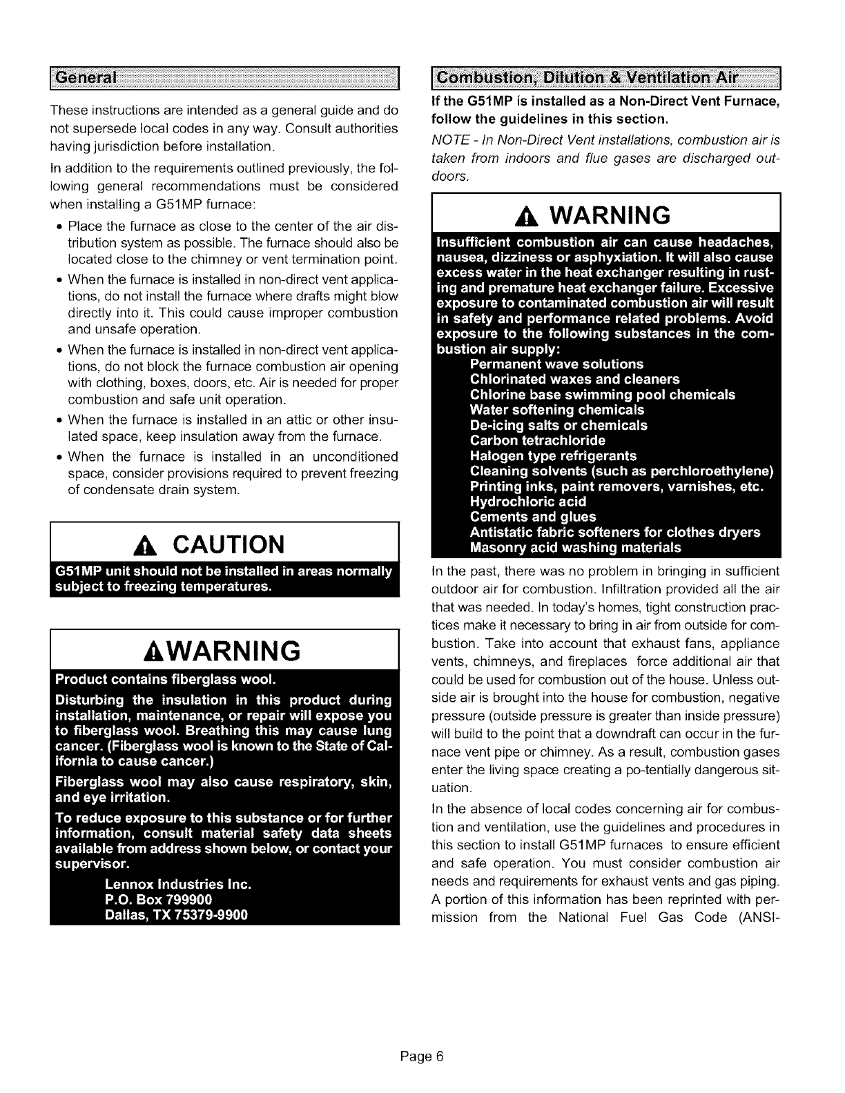
If the G51MP is installed as a Non-Direct Vent Furnace,
follow the guidelines in this section.
NOTE- In Non-Direct Vent installations, combustion air is
taken from indoors and flue gases are discharged out-
doors.
,& WARNING
,& CAUTION
-&WARNING
In the past, there was no problem in bringing in sufficient
outdoor air for combustion, Infiltration provided all the air
that was needed. In today's homes, tight construction prac-
tices make it necessary to bring in air from outside for com-
bustion, Take into account that exhaust fans, appliance
vents, chimneys, and fireplaces force additional air that
could be used for combustion out of the house, Unless out-
side air is brought into the house for combustion, negative
pressure (outside pressure is greater than inside pressure)
will build to the point that a downdraft can occur in the fur-
nace vent pipe or chimney, As a result, combustion gases
enter the living space creating a po-tentially dangerous sit-
uation,
In the absence of local codes concerning air for combus-
tion and ventilation, use the guidelines and procedures in
this section to install G51MP furnaces to ensure efficient
and safe operation. You must consider combustion air
needs and requirements for exhaust vents and gas piping.
A portion of this information has been reprinted with per-
mission from the National Fuel Gas Code (ANSI-
Page 6

Z223.1/NFPA54).Thisreprintedmaterialisnotthecom-
pleteandofficialpositionof theANSIonthereferenced
subject,whichisrepresentedonlybythestandardinitsen-
tirety.
InCanada,referto theCSAB149installationcodes.
,&CAUTION
All gas-fired appliances require air for the combustion pro-
cess. If sufficient combustion air is not available, the fur-
nace or other appliance will operate inefficiently and un-
safely. Enough air must be provided to meet the needs of
all fuel-burning appliances and appliances such as ex-
haust fans which force air out of the house. When fire-
places, exhaust fans, or clothes dryers are used at the
same time as the furnace, much more air is required to en-
sure proper combustion and to prevent a downdraft. Insuf-
ficient air causes incomplete combustion which can result
in carbon monoxide.
In addition to providing combustion air, fresh outdoor air di-
lutes contaminants in the indoor air. These contaminants
may include bleaches, adhesives, detergents, solvents
and other contaminants which can corrode furnace compo-
nents.
The requirements for providing air for combustion and ven-
tilation depend largely on whether the furnace is installed in
an unconfined or a confined space.
Unconfined Space
An unconfined space is an area such as a basement or
large equipment room with a volume greater than 50 cubic
feet (1.42 m3) per 1,000 Btu (.29 kW) per hour of the com-
bined input rating of all appliances installed in that space.
This space also includes adjacent rooms which are not
separated by a door. Though an area may appear to be un-
confined, it might be necessary to bring in outdoor air for
combustion if the structure does not provide enough air by
infiltration. If the furnace is located in a building of tight
construction with weather stripping and caulking around
the windows and doors, follow the procedures in the air
from outside section.
Confined Space
A confined space is an area with a volume less than 50 cu-
bic feet (1.42 m3) per 1,000 Btu (.29 kW) per hour of the
com-bined input rating of all appliances installed in that
space. This definition includes furnace closets or small
equipment rooms.
When the furnace is installed so that supply ducts carry air
circulated by the furnace to areas outside the space con-
taining the furnace, the return airmust be handled by ducts
which are sealed to the furnace casing and which terminate
outside the space containing the furnace. This is especially
important when the furnace is mounted on a platform in a
confined space such as a closet or small equipment room.
Even a small leak around the base of the unit at the platform
or at the return air duct connection can cause a potentially
dangerous negative pressure condition. Air for combustion
and ventilation can be brought into the confined space ei-
ther from inside the building or from outside.
Air from Inside
If the confined space that houses the furnace adjoins a
space categorized as unconfined, air can be brought in by
providing two permanent openings between the two
spaces. Each opening must have a minimum free area of 1
square inch (645 mm2) per 1,000 Btu (.29 kW) per hour of
total input rating of all gas-fired equipment in the confined
space. Each opening must be at least 100 square inches
(64516 mm2). One opening shall be within 12 inches (305
mm) of the top of the enclosure and one opening within 12
inches (305 mm) of the bottom. See figure 3.
EQUIPMENT IN CONFINED SPACE - ALL AIR FROM INSIDE
ROOF TERMINAl ED_1_ __,_
EXHAUST PIPE
f-
= -\ OPENINGS
-- (To Adjacent
SIDE WALL _ Unconfined
ERMINATED EX-
UST PIPE (ALTER- i __pace)
ATE LOCATION) G51MP #
Ill
,, ,, ,, ......... , ,, ,,
I I I I°
NOTE -Each opening shall have a free area of at least one square
inch per 1,000 Btu (645mm 2 per .29kW) per hour of the total input
rating of all equipment in the enclosure, but not less than 100 square
inches (64516mm. 2).
FIGURE 3
Air from Outside
If air from outside is brought in for combustion and ventila-
tion, the confined space shall be provided with two perma-
nent openings. One opening shall be within 12" (305mm) of
the top of the enclosure and one within 12" (305mm) of the
bottom. These openings must communicate directly or by
ducts with the outdoors or spaces (crawl or attic) that freely
communicate with the outdoors or indirectly through verti-
cal ducts. Each opening shall have a minimum free area of
1 square inch per 4,000 Btu (645mm 2 per 1.17kW) per hour
of total input rating of all equipment in the enclosure. When
communicating with the outdoors through horizontal ducts,
Page 7
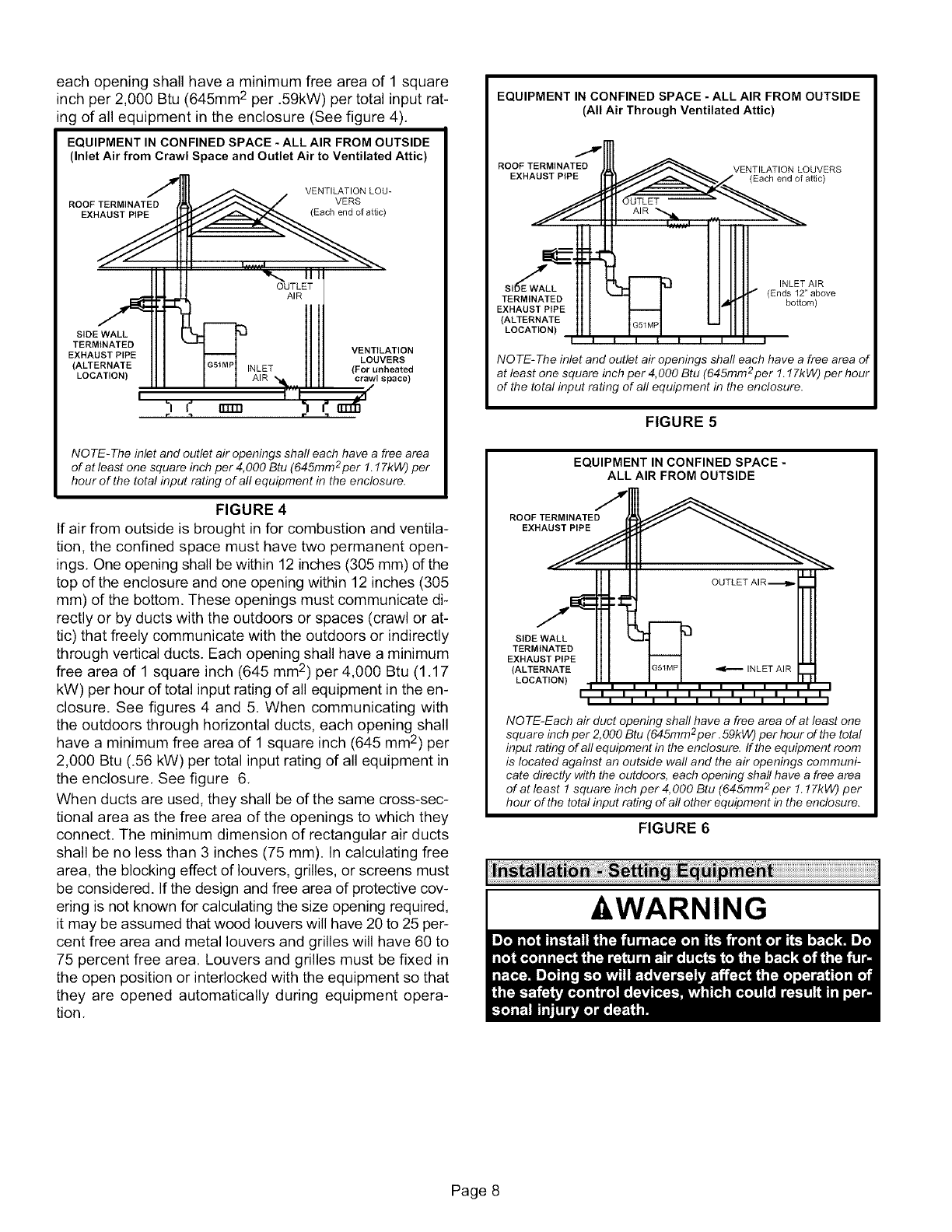
eachopeningshallhavea minimumfreeareaof1square
inchper2,000Btu(645mm2per.59kW)pertotalinputrat-
ingofallequipmentintheenclosure(Seefigure4),
EQUIPMENT IN CONFINED SPACE - ALL AIR FROM OUTSIDE
(Inlet Air from Crawl Space and Outlet Air to Ventilated Attic)
VENTILATION LOU-
ROOF TERMINATED VERS
EXHAUST PIPE (Each end of attic)
OUTLET
AIR
SIDE WALL
TERMINATED
EXHAUSTPIPE
(ALTERNATE
LOCATION) INLET
VENTILATION
LOUVERS
(For unheated
crawl space)
I
NOTE-The inlet and outlet air openings shall each have a free area
of at least one square inch per 4,000 Btu (645mm 2per 1.17kW) per
hour of the total input rating of all equipment in the enclosure.
FIGURE 4
If air from outside is brought in for combustion and ventila-
tion, the confined space must have two permanent open-
ings, One opening shall be within 12 inches (305 mm) of the
top of the enclosure and one opening within 12 inches (305
mm) of the bottom. These openings must communicate di-
rectly or by ducts with the outdoors or spaces (crawl or at-
tic) that freely communicate with the outdoors or indirectly
through vertical ducts. Each opening shall have a minimum
free area of 1 square inch (645 mm 2) per 4,000 Btu (1,17
kW) per hour of total input rating of all equipment in the en-
closure. See figures 4 and 5. When communicating with
the outdoors through horizontal ducts, each opening shall
have a minimum free area of 1 square inch (645 mm2) per
2,000 Btu (.56 kW) per total input rating of all equipment in
the enclosure, See figure 6,
When ducts are used, they shall be of the same cross-sec-
tional area as the free area of the openings to which they
connect. The minimum dimension of rectangular air ducts
shall be no less than 3 inches (75 mm). In calculating free
area, the blocking effect of louvers, grilles, or screens must
be considered. If the design and free area of protective cov-
ering is not known for calculating the size opening required,
it may be assumed that wood louvers will have 20 to 25 per-
cent free area and metal louvers and grilles will have 60 to
75 percent free area. Louvers and grilles must be fixed in
the open position or interlocked with the equipment so that
they are opened automatically during equipment opera-
tion,
I
EQUIPMENT IN CONFINED SPACE - ALL AIR FROM OUTSIDE
(All Air Through Ventilated Attic)
7
ROOF TERMINATED VENTILATION LOUVERS
EXHAUST PIPE (Each end of attic)
TERMINATED
EXHAUSTPtPE
(ALTERNATE
LOCATION)
INLET AIR
(Ends 12"above
bottom)
NOTE-The inlet and outlet air openings shall each have a free area of
at least one square inch per 4,000 Btu (645mm2per 1.17kW) per hour
of the total input rating of all equipment in the enclosure.
FIGURE 5
EQUIPMENT IN CONFINED SPACE -
ALL AIR FROM OUTSIDE
ROOF TERMINATED
EXHAUST PIPE
SIDE WALL
TERMINATED
EXHAUSTPIPE
(ALTERNATE
LOCATION)
NO TE-Each air duct opening shall have a free area of at least one
square inch per 2,000 Btu (645mm2per. 59kW) per hour of the total
input rating of all equipment in the enclosure. If the equipment room
is located against an outside wall and the air openings communi-
cate directly with the outdoors, each opening shall have a free area
of at least 1 square inch per 4, 000 Btu (645mm 2per 1.17kW) per
hour of the total input rating of all other equipment in the enclosure.
FIGURE 6
-&WARNING I
Page 8

Selecta locationthatallowsfor therequiredclearances
thatarelistedontheunitnameplate.Alsoconsidergas
supplyconnections,electricalsupply,ventconnection,
condensatetrapanddrainconnections,andinstallation
andserviceclearances[24inches(610mm)atunitfront].
The unit must be level from front to back and side to side.
NOTE -1/3 hp blower motors are equipped with four flex-
ible mounting legs, and 1/2 hp blower motors are equipped
with three flexible legs and one rigid leg. The rigid leg is
equipped with a shipping bolt and a flat white plastic wash-
er (rather than the rubber mounting grommet used with a
flexible mounting leg). The bolt and washer must be re-
moved before the furnace is placed into operation. Af-
ter the bolt and washer have been removed, the rigid leg
will not touch the blower housing.
Allow for clearances to combustible materials as indicated
on the unit nameplate. Minimum clearances for closet or al-
cove installations are shown in figures 7, 12 and 16.
WARNING
AWARNING
Upflow Applications
The G51MP gas furnace can be installed as shipped in the
upflow position. Refer to figure 7 for clearances.
Installation Clearances
Top
Left Side Right Side
J
Bottom (Floor)
............................................... T...............................................
Top/Plenum i1 in. (25 ram)
t
*Front iO
."................... ....................T..............................................
,,'.....................-.........................f...............................................I
Vent i O
=
Floor I O:_
*Front clearance in alcove installation must be 24 in. (610 ram).
Maintain a minimum of 24 in. (610 ram) for front service access.
tAllow proper clearances to accommodate condensate trap and
vent pipe installation.
! :_For installations on acombustible floor, do not install the fur-
inace directly on carpeting, tile or other combustible materials oth-
i er than wood flooring.
=================================================================================================
FIGURE 7
Return Air -- Upflow Units
Return air can be brought in through the bottom or either
side of the furnace installed in an upflow application. If the
furnace is installed on a platform with bottom return, make
an airtight seal between the bottom of the furnace and the
platform to ensure that the furnace operates properly and
safely. The furnace is equipped with a removable bottom
panel to facilitate installation,
Markings are provided on both sides of the furnace cabinet
for installations that require side return air. Cut the furnace
cabinet at the maximum dimensions shown on page 2,
NOTE -When air volumes over 1800 cfm (850 L/s) are
required with 60C or 60D models in an upflow applica-
tion, the following return air options are available:
1-Return air from single side with transition which will
accommodate 20 x 25 x I in. (508 x 635 x 25 ram) air filter.
(Required to maintain proper air velocity.) See figure 8.
2-Return air from single side with optional RAB Return
Air Base. See figure 10.
3-Return air from bottom.
4-Return air from both sides.
5-Return air from bottom and one side.
Page 9
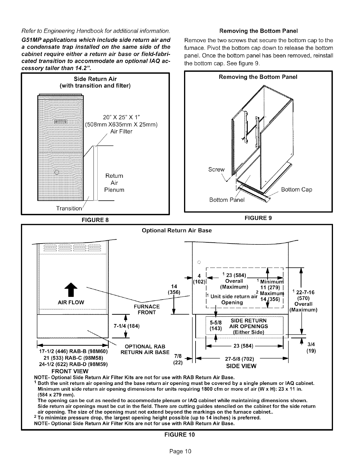
Refer to Engineering Handbook for additional information.
G51MP applications which include side return air and
a condensate trap installed on the same side of the
cabinet require either a return air base or field-fabri-
cated transition to accommodate an optional IAQ ac-
cessory taller than 14.2".
Side Return Air
(with transition and filter)
20" X 25" X 1"
(508mm X635mm X 25mm)
Air Filter
_/
Return
Air
Plenum
Removing the Bottom Panel
Remove the two screws that secure the bottom cap to the
furnace. Pivot the bottom cap down to release the bottom
panel, Once the bottom panel has been removed, reinstall
the bottom cap, See figure 9,
Removing the Bottom Panel
Screw
\./
Bottom
Bottom Cap
FIGURE 8FIGURE 9
Optional Return Air Base
©' -fL
-I_ 4 I123 (584)
(102)r 91"-- Overall 1 Minimu"-_
t14 I (Maximum) 11 (279) I
Maximun_
I1Unit side return air 16)
AIR FLOW Opening |
.................................................................................. FURNACE J, __ __i
FRONT L
5-5/8 SIDE RETURN
7-1/4 (184) t143_ AiR OPENINGS
""(Either Side)
_ _ OPTIONAL RAB ql_ 23 (584) _
17-1/2 (446) RAB-B (98M60) RETURN AiR BASE
21 (533) RAB-C (98M58) 7/8 -I_ _1-- 27-5/8 (702)
24-1/2 (622) RAB-D (98M59) (22) SIDE VIEW
FRONT VIEW
NOTE- Optional Side Return Air Filter Kits are not for use with RAB Return Air Base.
1 Both the unit return air opening and the base return air opening must be covered by a single plenum or IAQ cabinet.
Minimum unit side return air opening dimensions for units requiring 1800 cfm or more of air (W x H): 23 x 11 in.
(584 x 279 mm).
The opening can be cut as needed to accommodate plenum or IAQ cabinet while maintaining dimensions shown.
Side return air openings must be cut in the field. There are cutting guides stenciled on the cabinet for the side return
air opening. The size of the opening must not extend beyond the markings on the furnace cabinet..
2 To minimize pressure drop, the largest opening height possible (up to 14 inches) is preferred.
NOTE- Optional Side Return Air Filter Kits are not for use with RAB Return Air Base.
122-7-16
(570)
Overall
Maximum)
_l
_3/4
(19)
FIGURE 10
Page 10
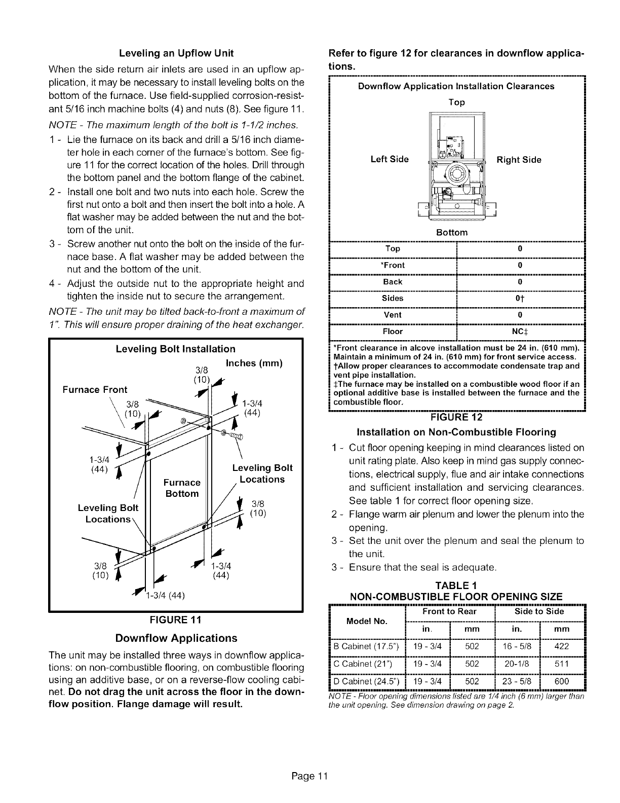
Levelingan Upflow Unit
When the side return air inlets are used in an upflow ap-
plication, it may be necessary to install leveling bolts on the
bottom of the furnace. Use field-supplied corrosion-resist-
ant 5/16 inch machine bolts (4) and nuts (8). See figure 11.
NOTE -The maximum length of the bolt is 1-1/2 inches.
1 - Lie the furnace on its back and drill a 5/16 inch diame-
ter hole in each corner of the furnace's bottom. See fig-
ure 11 for the correct location of the holes. Drill through
the bottom panel and the bottom flange of the cabinet.
2 - Install one bolt and two nuts into each hole. Screw the
first nut onto a bolt and then insert the bolt into a hole. A
flat washer may be added between the nut and the bot-
tom of the unit.
3 - Screw another nut onto the bolt on the inside of the fur-
nace base. A flat washer may be added between the
nut and the bottom of the unit.
4 - Adjust the outside nut to the appropriate height and
tighten the inside nut to secure the arrangement.
NOTE -The unit may be tilted back-to-front a maximum of
1". This will ensure proper draining of the heat exchanger.
Leveling Bolt Installation
Inches (mm)
3/8
Furnace Front _¢
3/8 1-3/4
(44)
1-3/4
(44)
Leveling Bolt
Furnace
Bottom
Leveling Bolt
Locations
3/8
(1o)
3/8 1-3/4
(10) (44)
I-3/4 (44)
FIGURE 11
Downflow Applications
The unit may be installed three ways in downflow applica-
tions: on non-combustible flooring, on combustible flooring
using an additive base, or on a reverse-flow cooling cabi-
net. Do not drag the unit across the floor in the down-
flow position. Flange damage will result.
Refer to figure 12 for clearances in downflow applica-
tions.
•............................................................................................... q
Downflow Application Installation Clearances
Left Side
Top
Right Side
J
Bottom
&,I
............................................... T...............................................
Top i O
*Front IO
."................... ....................T..............................................
Sides i Ot
]
Vent i O
............................................... t ................................................
Floor i NC_:
*Front clearance in alcove installation must be 24 in. (616 ram).
Maintain a minimum of 24 in. (610 ram) for front service access.
tAllow proper clearances to accommodate condensate trap and
vent pipe installation.
_:The furnace may be installed on a combustible wood floor if an
i optional additive base is installed between the furnace and the
i combustible floor.
=================================================================================================
FIGURE 12
Installation on Non-Combustible Flooring
1 - Cut floor opening keeping in mind clearances listed on
unit rating plate. Also keep in mind gas supply connec-
tions, electrical supply, flue and air intake connections
and sufficient installation and servicing clearances.
See table 1 for correct floor opening size.
2 - Flange warm air plenum and lower the plenum into the
opening.
3 - Set the unit over the plenum and seal the plenum to
the unit.
3 - Ensure that the seal is adequate.
TABLE 1
NON-COMBUSTIBLE FLOOR OPENING SIZE
i............................[...... 'ronno' e;r"......[...... ........i
iModel No. _................................. _.................................
iii i•
i"i i "i •
I In. I mm I In. I mm I
iii i•
I, ,! ,I -I., I.
jBCabinet(17.5") i19-3/4, ,i 502 ,i 16-5/8 ,i 422 j
I, ,! ,I -I., I.
jCCabinet(21") ,i 19-3/4 ,i 502 ,i 20-1/8 ,i 511 j
I, ,! ,I -I., I.
•."-
• DCabmet(245) , 19 3/4 , 502 , 23 5/8 , 600 •
i............................[................L................[................[................i
NOTE -Floor opening dimensions listed are 1/4 inch (6 mm) larger than
the unit opening. See dimension drawing on page 2.
Page 11
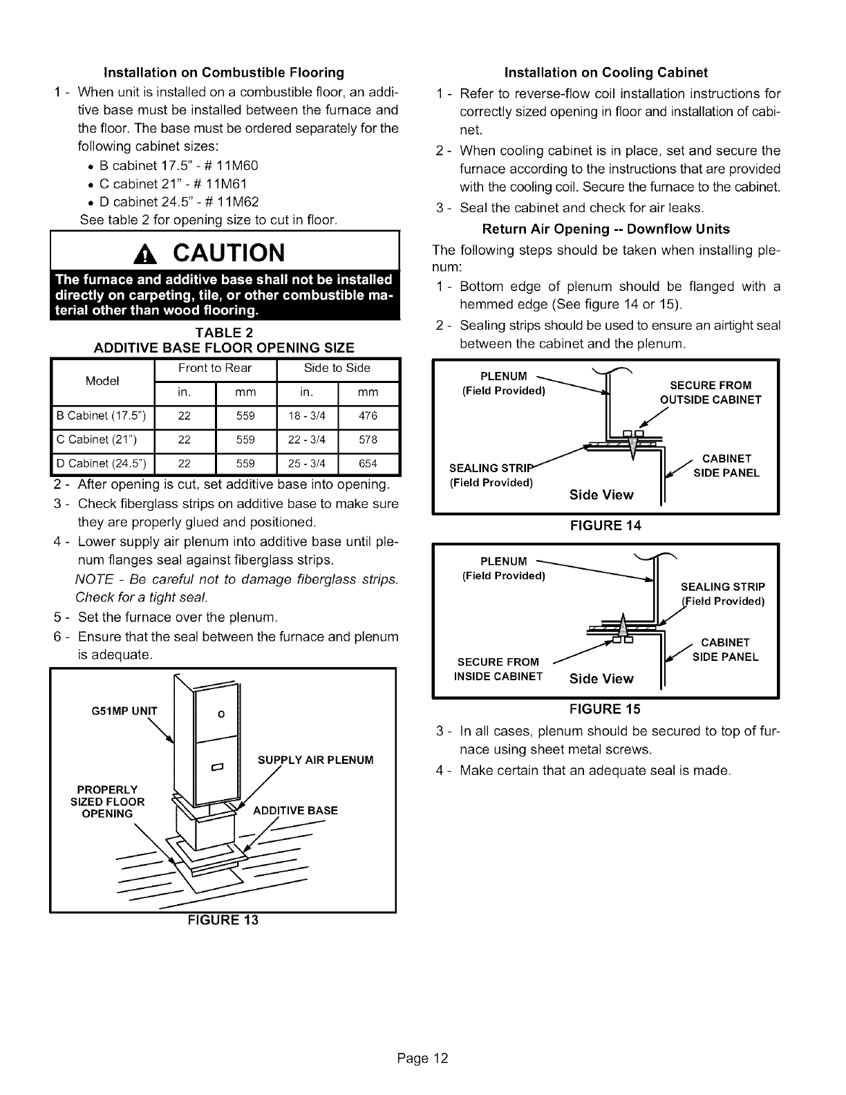
Installation on Combustible Flooring
1 - When unit is installed on a combustible floor, an addi-
tive base must be installed between the furnace and
the floor. The base must be ordered separately for the
following cabinet sizes:
• B cabinet 17,5" - # 11M60
• C cabinet21"-# 11M61
• D cabinet 24,5" - # 11M62
See table 2 for opening size to cut in floor.
Ak CAUTION
TABLE 2
ADDITIVE BASE FLOOR OPENING SIZE
Model am
B Cabinet (17.5") 476
C Cabinet (21") 578
D Cabinet (24.5") 654
Frontto Rear
in. mm
22 559
22 559
22 559
Side to Side
in.
18 - 3/4
22 - 3/4
25 - 3/4
2 - After opening is cut, set additive base into opening.
3 - Check fiberglass strips on additive base to make sure
they are properly glued and positioned,
4 - Lower supply air plenum into additive base until ple-
num flanges seal against fiberglass strips.
NOTE -Be careful not to damage fiberglass strips,
Check for a tight seal,
5 - Set the furnace over the plenum.
6 - Ensure that the seal between the furnace and plenum
is adequate.
G51MP UNIT_ __T
SUPPLY AIR PLENUM
PROPERLY ,VEBASE
FIGURE 13
Installation on Cooling Cabinet
1 - Refer to reverse-flow coil installation instructions for
correctly sized opening in floor and installation of cabi-
net,
2 - When cooling cabinet is in place, set and secure the
furnace according to the instructions that are provided
with the cooling coil, Secure the furnace to the cabinet,
3 - Seal the cabinet and check for air leaks.
Return Air Opening -- Downflow Units
The following steps should be taken when installing ple-
num:
1-Bottom edge of plenum should be flanged with a
hemmed edge (See figure 14 or 15).
2 - Sealing strips should be used to ensure an airtight seal
between the cabinet and the plenum.
PLENUM ---,,_ _11 '''_
(Field Provided) _ SECURE FROM
•_UTSIDE CABINET
v II _ CABINET
SEAL,NGSTR, IlJ S,DEPANEL
(Field Provided) ...... II
Side View II
FIGURE 14
PLENUM _'_
(Field Provided_-..h.
SECURE FROM
INSIDE CABINET Side View
SEALING STRIP
,_Field Provided)
jCABINET
, SIDE PANEL
FIGURE 15
3 - In all cases, plenum should be secured to top of fur-
nace using sheet metal screws,
4 - Make certain that an adequate seal is made.
Page 12
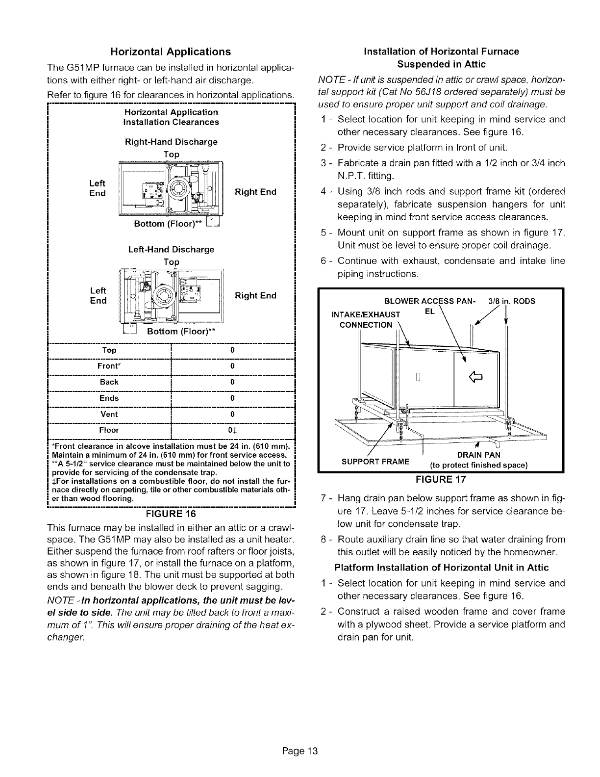
Horizontal Applications
The G51MP furnace can be installed in horizontal applica-
tions with either right- or left-hand air discharge.
Refer to figure 16 for clearances in horizontal applications,
H===================mmmmmmHHHmmmmmmHHHmmmmmmHHHmmmmmmHHHm.
Horizontal Application
Installation Clearances
Right-Hand Discharge
Top
Left
End Right End
Left-Hand Discharge
Top
Left
End Right End
Top ] O
i................... ron;:...................i.............................................i
Back 1O
".................... ....................i"..............................................
i
Vent !o
=
...................." oor"...................T.....................;;.......................
| ............................................... _ ................................................
*Front clearance in alcove installation must be 24 in. (610 ram).
Maintain a minimum of 24 in. (610 ram) for front service access.
**A 5-1/2" service clearance must be maintained below the unit to
provide for servicing of the condensate trap.
_:For installations on a combustible floor, do not install the fur-
nace directly on carpeting, tile or other combustible materials oth-
er than wood flooring.
FIGURE 16
This furnace may be installed in either an attic or a crawl-
space. The G51MP may also be installed as a unit heater.
Either suspend the furnace from roof rafters or floor joists,
as shown in figure 17, or install the furnace on a platform,
as shown in figure 18. The unit must be supported at both
ends and beneath the blower deck to prevent sagging,
NOTE -In horizontal applications, the unit must be lev-
el side to side. The unit may be tilted back to front a maxi-
mum of 1': This willensure proper draining of the heat ex-
changer.
Installation of Horizontal Furnace
Suspended in Attic
NOTE -If unit is suspended in attic or crawl space, horizon-
tal support kit (Cat No 56J18 ordered separately) must be
used to ensure proper unit support and coil drainage.
1 - Select location for unit keeping in mind service and
other necessary clearances, See figure 16.
2 - Provide service platform in front of unit,
3 - Fabricate a drain pan fitted with a 1/2 inch or 3/4 inch
N,P,T, fitting.
4- Using 3/8 inch rods and support frame kit (ordered
separately), fabricate suspension hangers for unit
keeping in mind front service access clearances.
5 - Mount unit on support frame as shown in figure 17.
Unit must be level to ensure proper coil drainage,
6- Continue with exhaust, condensate and intake line
piping instructions,
BLOWER ACCESS PAN- 3/8 in. RODS
INTAKE/EXHAUST EL
CONNECTION
DRAIN PAN
SUPPORT FRAME (to protect finished space)
FIGURE 17
7 - Hang drain pan below support frame as shown in fig-
ure 17. Leave 5-1/2 inches for service clearance be-
low unit for condensate trap,
8 - Route auxiliary drain line so that water draining from
this outlet will be easily noticed by the homeowner,
Platform Installation of Horizontal Unit in Attic
1 - Select location for unit keeping in mind service and
other necessary clearances. See figure 16,
2 - Construct a raised wooden frame and cover frame
with a plywood sheet, Provide a service platform and
drain pan for unit,
Page 13
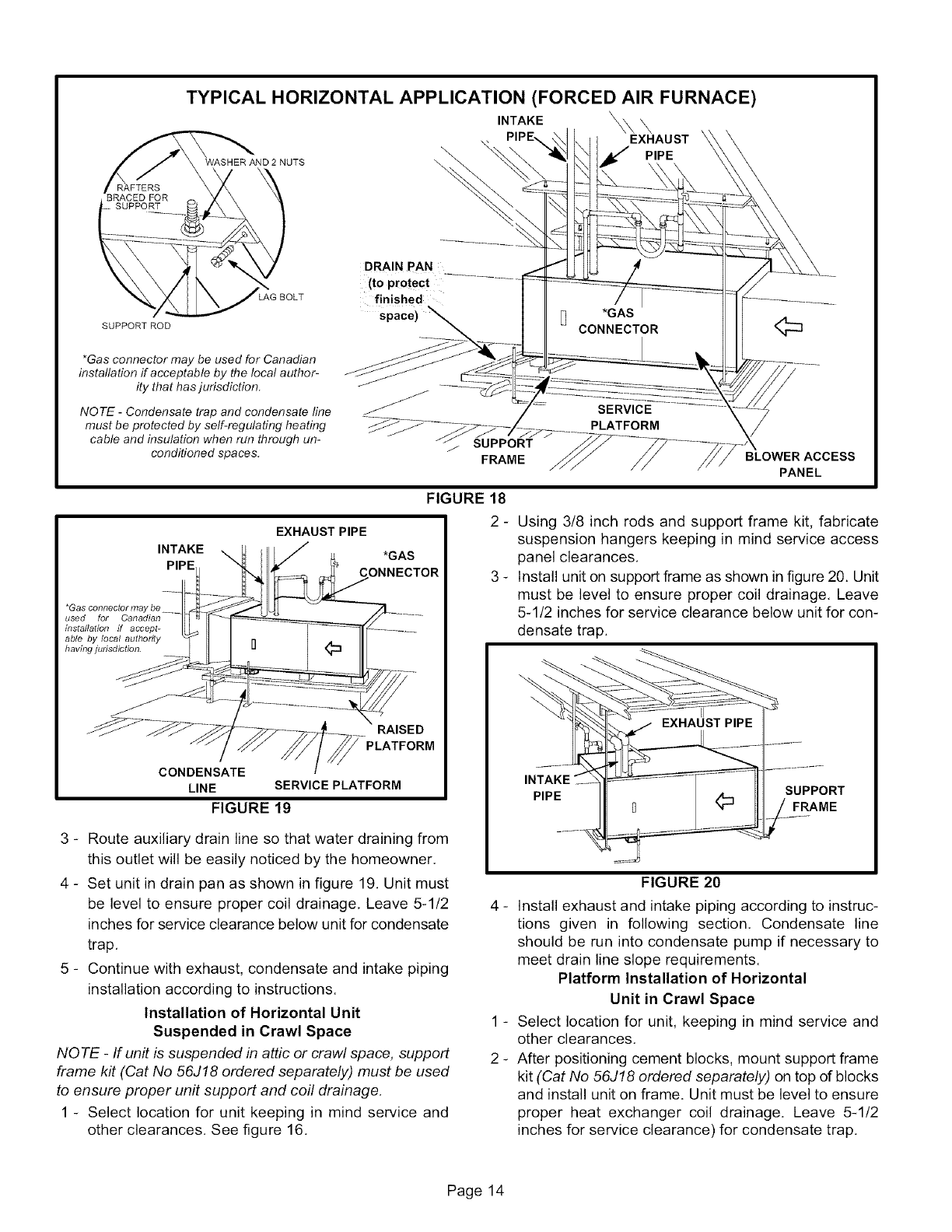
TYPICAL HORIZONTAL APPLICATION (FORCED AIR FURNACE)
WASHER AND 2 NUTS
BRACED FOR
SUPPORT
INTAKE \Xx\
EXHAUST
PIPE
LAG BOLT
SUPPORT ROD
*Gas connector may be used for Canadian
installation if acceptable by the local author-
ity that has jurisdiction.
NOTE -Condensate trap and condensate line
must be protected by self-regulating heating
cable and insulation when run through un-
conditioned spaces.
DRAIN PAN
(to protect ............
finished
space)
/SUPPORT
FRAME
INTAKE
*Gas connector ma
used for Canadian
installation ff accept-
able by local authority
having judsdJction.
FIGURE 18
EXHAUST PIPE
*GAS
CONNECTOR
RAISED
CONDENSATE
LINE SERVICE PLATFORM
FIGURE 19
3 - Route auxiliary drain line so that water draining from
this outlet will be easily noticed by the homeowner.
4 - Set unit in drain pan as shown in figure 19. Unit must
be level to ensure proper coil drainage, Leave 5-1/2
inches for service clearance below unit for condensate
trap,
5 - Continue with exhaust, condensate and intake piping
installation according to instructions.
Installation of Horizontal Unit
Suspended in Crawl Space
NOTE -If unit is suspended in attic or crawl space, support
frame kit (Cat No 56J18 ordered separately) must be used
to ensure proper unit support and coil drainage.
1 - Select location for unit keeping in mind service and
other clearances, See figure 16,
BLOWER ACCESS
PANEL
2 - Using 3/8 inch rods and support frame kit, fabricate
suspension hangers keeping in mind service access
panel clearances,
3 - Install unit on support frame as shown in figure 20. Unit
must be level to ensure proper coil drainage, Leave
5-1/2 inches for service clearance below unit for con-
densate trap.
INTAKE
PIPE SUPPORT
FRAME
FIGURE 20
4 - Install exhaust and intake piping according to instruc-
tions given in following section. Condensate line
should be run into condensate pump if necessary to
meet drain line slope requirements.
Platform Installation of Horizontal
Unit in Crawl Space
1 - Select location for unit, keeping in mind service and
other clearances,
2 - After positioning cement blocks, mount support frame
kit (Cat No 56J18 ordered separately) on top of blocks
and install unit on frame. Unit must be level to ensure
proper heat exchanger coil drainage. Leave 5-1/2
inches for service clearance) for condensate trap,
Page 14
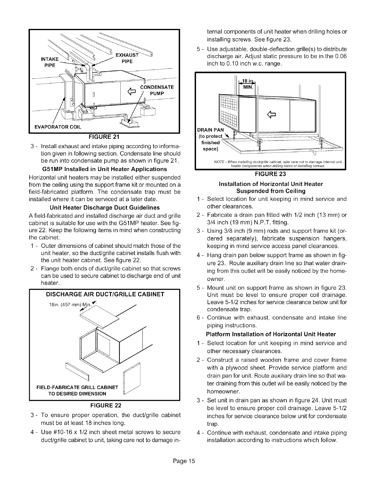
INTAKE
PIPE
EVAPORATOR COIL
FIGURE 21
3 - Install exhaust and intake piping according to informa-
tion given in following section. Condensate line should
be run into condensate pump as shown in figure 21,
G51MP Installed in Unit Heater Applications
Horizontal unit heaters may be installed either suspended
from the ceiling using the support frame kit or mounted on a
field-fabricated platform. The condensate trap must be
installed where it can be serviced at a later date,
Unit Heater Discharge Duct Guidelines
A field-fabricated and installed discharge air duct and grille
cabinet is suitable for use with the G51MP heater, See fig-
ure 22. Keep the following items in mind when constructing
the cabinet.
1 - Outer dimensions of cabinet should match those of the
unit heater, so the duct/grille cabinet installs flush with
the unit heater cabinet. See figure 22.
2 - Flange both ends of duct/grille cabinet so that screws
can be used to secure cabinet to discharge end of unit
heater.
DISCHARGE AIR DUCT/GRILLE CABINET
18in. (457 mm) Ik _"
FIELD-FABRICATE GRILL CABINET
TO DESIRED DIMENSION
FIGURE 22
3- To ensure proper operation, the duct/grille cabinet
must be at least 18 inches long,
4 - Use #10-16 x 1/2 inch sheet metal screws to secure
duct/grille cabinet to unit, taking care not to damage in-
ternal components of unit heater when drilling holes or
installing screws. See figure 23,
5 - Use adjustable, double-deflection grille(s) to distribute
discharge air. Adjust static pressure to be in the 0,06
inch to 0,10 inch w,c, range,
DRAIN PAN
(to protect '_
finished
space)
NOTE -When installing duct/grille cabinet, take care not to damage internal unit
heater components when dnlhng holes or installing screws.
FIGURE 23
Installation of Horizontal Unit Heater
Suspended from Ceiling
1 - Select location for unit keeping in mind service and
other clearances.
2 - Fabricate a drain pan fitted with 1/2 inch (13 mm) or
3/4 inch (19 mm) N.P.T. fitting.
3 - Using 3/8 inch (9 mm) rods and support frame kit (or-
dered separately), fabricate suspension hangers,
keeping in mind service access panel clearances.
4 - Hang drain pan below support frame as shown in fig-
ure 23, Route auxiliary drain line so that water drain-
ing from this outlet will be easily noticed by the home-
owner,
5 - Mount unit on support frame as shown in figure 23.
Unit must be level to ensure proper coil drainage.
Leave 5-1/2 inches for service clearance below unit for
condensate trap,
6- Continue with exhaust, condensate and intake line
piping instructions.
Platform Installation of Horizontal Unit Heater
1 - Select location for unit keeping in mind service and
other necessary clearances.
2 - Construct a raised wooden frame and cover frame
with a plywood sheet. Provide service platform and
drain pan for unit, Route auxiliary drain line so that wa-
ter draining from this outlet will be easily noticed by the
homeowner,
3 - Set unit in drain pan as shown in figure 24, Unit must
be level to ensure proper coil drainage, Leave 5-1/2
inches for service clearance below unit for condensate
trap.
4 - Continue with exhaust, condensate and intake piping
installation according to instructions which follow.
Page 15
INTAKE
PIPE
*GAS CONNECTOR
*Gas connector may be
used for Canadian instal-
lation ff acceptable by b-
ca/authority having juns-
diction.
RAISE
CONDENSATE LINE PLATFORM
FIGURE 24
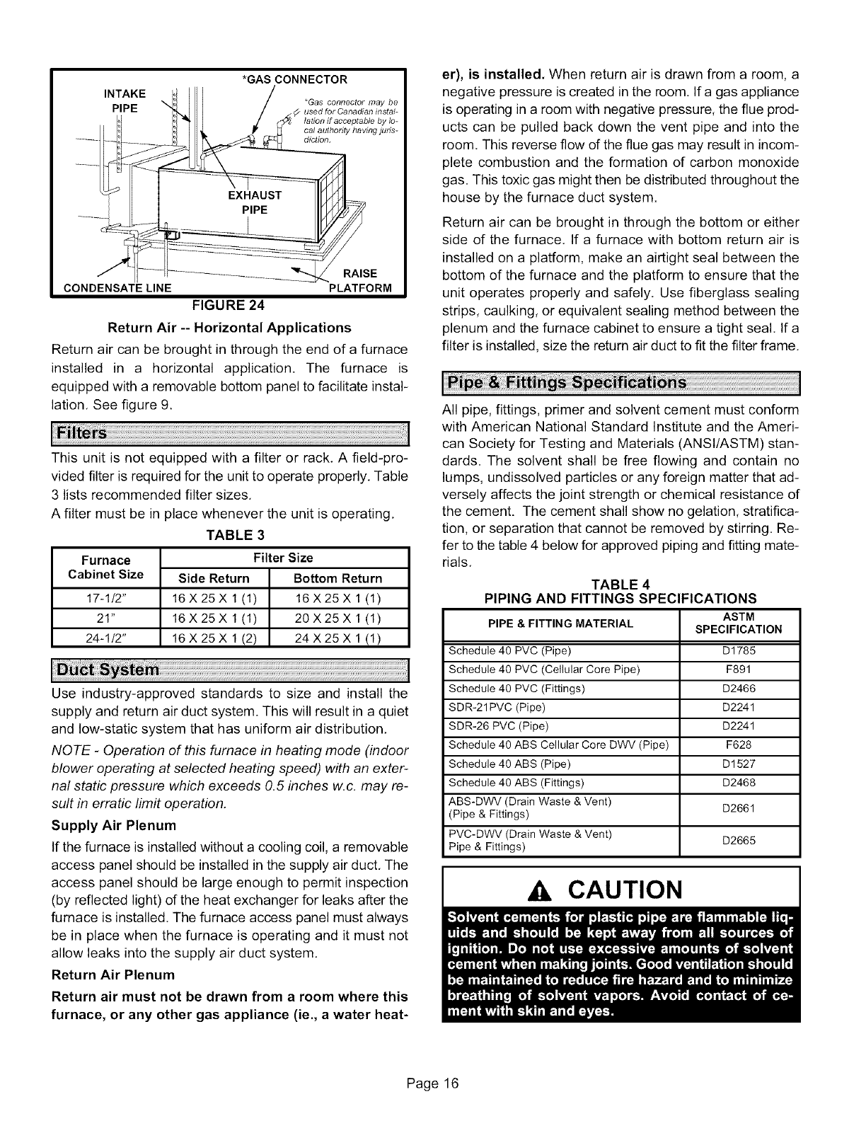
Return Air -- Horizontal Applications
Return air can be brought in through the end of a furnace
installed in a horizontal application. The furnace is
equipped with a removable bottom panel to facilitate instal-
lation, See figure 9.
This unit is not equipped with a filter or rack, A field-pro-
vided filter is required for the unit to operate properly, Table
3 lists recommended filter sizes,
A filter must be in place whenever the unit is operating,
TABLE 3
Furnace
Cabinet Size
17-1/2"
21"
24-1/2"
Filter Size
Side Return Bottom Return
16X25X 1(1) 16X25Xl(1)
16X25X 1(1) 20X25Xl(1)
16X25X 1(2) 24X25Xl(1)
Use industry-approved standards to size and install the
supply and return air duct system. This will result in a quiet
and low-static system that has uniform air distribution.
NOTE - Operation of this furnace in heating mode (indoor
blower operating at selected heating speed) with an exter-
nal static pressure which exceeds 0.5 inches w.c. may re-
sult in erratic limit operation.
Supply Air Plenum
If the furnace is installed without a cooling coil, a removable
access panel should be installed in the supply air duct, The
access panel should be large enough to permit inspection
(by reflected light) of the heat exchanger for leaks after the
furnace is installed, The furnace access panel must always
be in place when the furnace is operating and it must not
allow leaks into the supply air duct system,
Return Air Plenum
Return air must not be drawn from a room where this
furnace, or any other gas appliance (ie., a water heat-
er), is installed. When return air is drawn from a room, a
negative pressure is created in the room, If a gas appliance
is operating in a room with negative pressure, the flue prod-
ucts can be pulled back down the vent pipe and into the
room, This reverse flow of the flue gas may result in incom-
plete combustion and the formation of carbon monoxide
gas. This toxic gas might then be distributed throughout the
house by the furnace duct system.
Return air can be brought in through the bottom or either
side of the furnace, If a furnace with bottom return air is
installed on a platform, make an airtight seal between the
bottom of the furnace and the platform to ensure that the
unit operates properly and safely. Use fiberglass sealing
strips, caulking, or equivalent sealing method between the
plenum and the furnace cabinet to ensure a tight seal. If a
filter is installed, size the return air duct to fit the filter frame.
All pipe, fittings, primer and solvent cement must conform
with American National Standard Institute and the Ameri-
can Society for Testing and Materials (ANSI/ASTM) stan-
dards. The solvent shall be free flowing and contain no
lumps, undissolved particles or any foreign matter that ad-
versely affects the joint strength or chemical resistance of
the cement. The cement shall show no gelation, stratifica-
tion, or separation that cannot be removed by stirring. Re-
fer to the table 4 below for approved piping and fitting mate-
rials.
TABLE 4
PIPING AND FITTINGS SPECIFICATIONS
ASTM
PIPE & FITTING MATERIAL SPECIFICATION
Schedule 40 PVC (Pipe) D1785
Schedule 40 PVC (Cellular Core Pipe) F891
Schedule 40 PVC (Fittings) D2466
SDR-21PVC (Pipe) D2241
SDR-26 PVC (Pipe) D2241
Schedule 40 ABS Cellular Core DWV (Pipe) F628
Schedule 40 ABS (Pipe) D1527
Schedule 40 ABS (Fittings) D2468
ABS-DWV (Drain Waste & Vent) D2661
(Pipe & Fittings)
PVC-DWV (Drain Waste & Vent) D2665
Pipe & Fittings)
Ak CAUTION
Page 16
Primersand solventsmustmeetASTMspecifications.
PVCprimerisspecifiedinASTMF656.UsePVCsolvent
cementasspecifiedinASTMD2564andABSsolventce-
mentasspecifiedinASTMD2235.Lowtemperaturesol-
ventcementis recommended.Metalorplasticstrapping
maybeusedforventpipehangers,
WhenmakingABSjoints,piecescanbepreparedwitha
cleaner.WhenjoiningABStoPVCmaterials,usePVCsol-
ventcement,Referto the procedurespecifiedinASTM
D3138,
Canadian Applications Only -Pipe, fittings, primer and sol-
TABLE 5
OUTDOOR TERMINATION KITS AND CORRESPONDING EQUlVALENClES
Vent Pipe Length Equivalency (feet)
Outdoor
VENT Exhaust
UNIT PIPE Accelerator
MODEL DIA. (Dia. X
(in.) Length)
Outdoor
Exhaust
Accelera-
tor
(Dia. X
Length)
1-1/2"
Concen-
tric Kit
2" Con-
centric
Kit
vent cement used to vent this appliance must be certified to
ULC $636 and supplied by a single manufacturer as part of
an approved venting system. When bonding the vent sys-
tem to the furnace, use ULC $636 approved One-Step
Transition Cement to bond the pipe to the flue collar, 90°
elbow or reducing 90 °elbow as applicable. In addition, the
first three feet of vent pipe from the furnace flue collar must
be accessible for inspection.
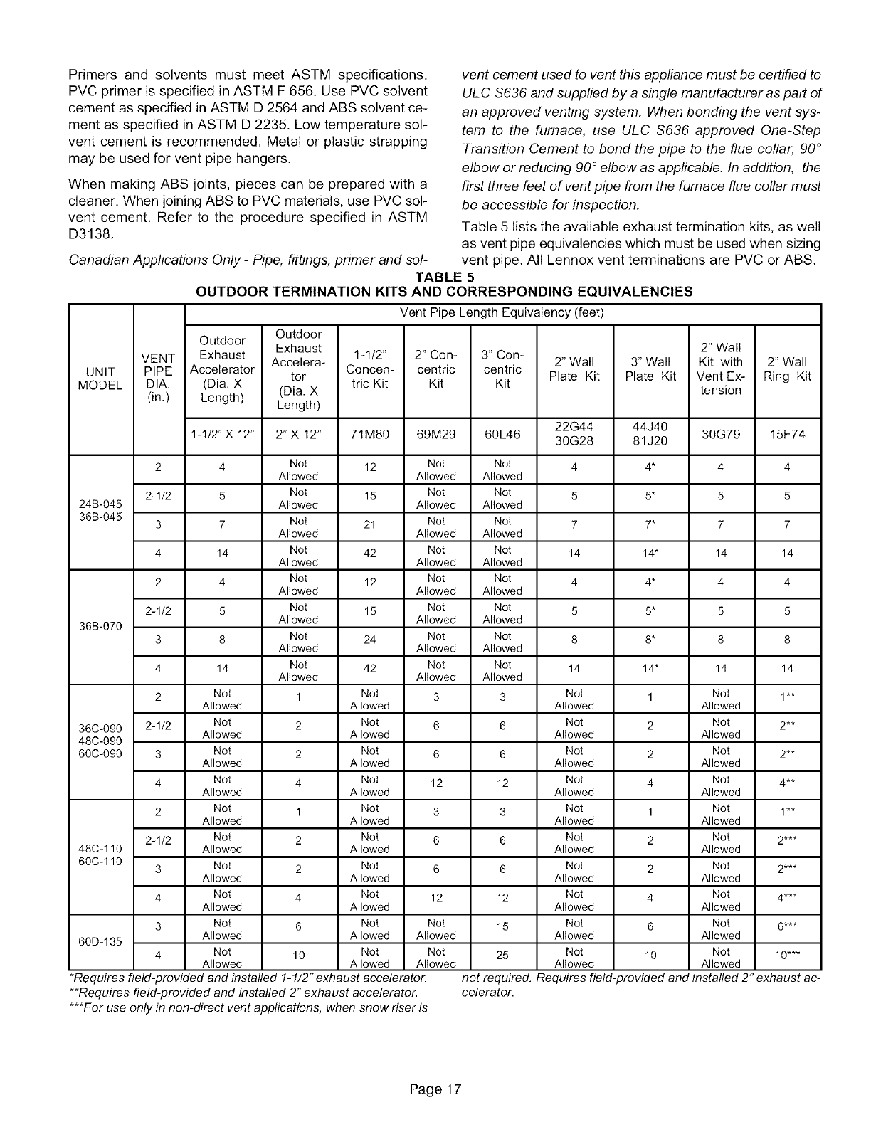
Table 5 lists the available exhaust termination kits, as well
as vent pipe equivalencies which must be used when sizing
vent pipe. All Lennox vent terminations are PVC or ABS.
2" Wall
Plate Kit
3" Wall
Plate Kit
3" Con-
centric
Kit
2" Wall
Kit with
Vent Ex-
tension
2" Wall
Ring Kit
22G44 44J40
1-1/2" X 12" 2" X 12" 71M80 69M29 60L46 30G28 81J20 30G79 15F74
2 4 Not 12 Not Not 4 4* 4 4
Allowed Allowed Allowed
2-1/2 5 Not 15 Not Not 5 5* 5 5
24B-045 Allowed Allowed Allowed
36B-045 3 7 Not 21 Not Not 7 7* 7 7
Allowed Allowed Allowed
4 14 Not 42 Not Not 14 14" 14 14
Allowed Allowed Allowed
2 4 Not 12 Not Not 4 4* 4 4
Allowed Allowed Allowed
2-1/2 5 Not 15 Not Not 5 5* 5 5
Allowed Allowed Allowed
36B-070
3 8 Not 24 Not Not 8 8* 8 8
Allowed Allowed Allowed
4 14 Not 42 Not Not 14 14" 14 14
Allowed Allowed Allowed
2 Not 1 Not 3 3 Not 1 Not 1**
Allowed Allowed Allowed Allowed
36C-090 2-1/2 Not 2 Not 6 6 Not 2 Not 2**
Allowed Allowed Allowed Allowed
48C-090
60C-090 3 Not 2 Not 6 6 Not 2 Not 2**
Allowed Allowed Allowed Allowed
4 Not 4 Not 12 12 Not 4 Not 4**
Allowed Allowed Allowed Allowed
2 Not 1 Not 3 3 Not 1 Not 1**
Allowed Allowed Allowed Allowed
2-1/2 Not 2 Not 6 6 Not 2 Not 2***
48C-110 Allowed Allowed Allowed Allowed
60C-110 3 Not 2 Not 6 6 Not 2 Not 2***
Allowed Allowed Allowed Allowed
4 Not 4 Not 12 12 Not 4 Not 4***
Allowed Allowed Allowed Allowed
3 Not 6 Not Not 15 Not 6 Not 6***
Allowed Allowed Allowed Allowed Allowed
60D-135
4 Not 10 Not Not 25 Not 10 Not 10"**
Allowed Allowed Allowed Allowed Allowed
not required. Requires field-provided and installed 2" exhaust ac-
celerator.
*Requires field-provided and installed 1-1/2" exhaust accelerator.
**Requires field-provided and installed 2" exhaust accelerator.
***For use only in non-direct vent applications, when snow riser is
Page 17

The G51MP can be installed as either a Non-Direct Vent
or a Direct Vent gas central furnace.
NOTE -In Non-Direct Vent installations, combustion air is
taken from indoors and flue gases are discharged out-
doors. In Direct Vent installations, combustion air is taken
from outdoors and flue gases are discharged outdoors.
Intake and exhaust pipe sizing in Direct Vent applications
and exhaust pipe sizing in Non-Direct Vent applications --
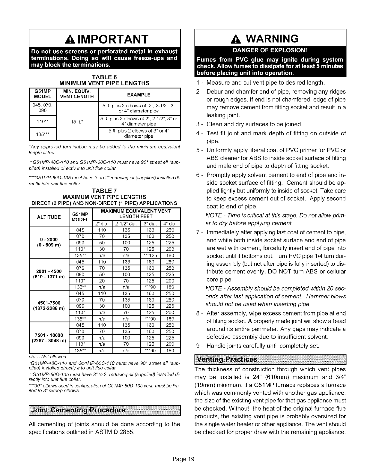
Size pipe according to tables 6 and 7. Table 6 lists the mini-
mum equivalent vent pipe lengths permitted. Table 7 lists
the maximum equivalent pipe lengths permitted.
Maximum vent length is defined as:
Total length (linear feet) of pipe,
Plus Equivalent length (feet) of fittings,
Plus Equivalent length (feet) of termination.
NOTE -Include ALL pipe and ALL fittings, both in
doors and outdoors.
Regardless of the diameter of pipe used, the standard roof
and wall terminations described in section Exhaust Piping
Terminations should be used. Exhaust vent termination
pipe is sized to optimize the velocity of the exhaust gas as it
exits the termination. Refer to table 8.
*NOTE -The exhaust pipe should be offset a minimum of
12 inches to avoid the possibility of water droplets being re-
leased from the exhaust termination. The minimum ex-
haust vent length is 15 ft. Shorter exhaust vent lengths may
result in the discharge of water droplets from the exhaust
termination, in spite of the 12-inch vertical offset. See figure
25.
Each 90° elbow (including those provided with the furnace)
of any diameter is equivalent to 5 feet (1.52m) of vent pipe
of the same diameter. Two 45° elbows are equivalent to
one 90° elbow of the same diameter, One 45° elbow is
equal to 2,5 feet (,76m) of vent pipe of the same diameter,
In some applications which permit the use of several differ-
ent sizes of vent pipe, a combination vent pipe may be
used. Contact Lennox' Application Department for assis-
tance in sizing vent pipe in these applications,
NQ TE -The flue collar on all models is sized to accommo-
date 2" Schedule 40 flue pipe. When vent pipe which is
larger than 2" must be used in an upflow application, a 2"
elbow must be applied at the flue collar in order to properly
transition to the larger diameter flue pipe. This elbow must
be added to the elbow count used to determine acceptable
vent lengths. Assign an equivalent feet value to this elbow
according to the larger size pipe being used. Contact the
Application Department for more information concerning
sizing of vent systems which include multiple pipe sizes.
Use the following steps to correctly size vent pipe diameter,
Refer to Vent Pipe Size Determination Worksheet on
page 48.
1 - Determine the vent termination and its corresponding
equivalent feet value according to table 5.
2 - Determine the number of 90° elbows required for both
indoor and outdoor (e,g. snow riser) use, Calculate the
corresponding equivalent feet of vent pipe.
3 - Determine the number of 45° elbows required for both
indoor and outdoor use, Calculate the corresponding
equivalent feet of vent pipe,
4 - Determine the length of straight pipe required,
5- Add the total equivalent feet calculated in steps 1
through 4 and compare that length to the maximum
values given in table 7 for the proposed vent pipe di-
ameter. If the total equivalent length required exceeds
the maximum equivalent length listed in the appropri-
ate table, evaluate the next larger size pipe,
Exhaust Pipe Offset
I
I
I
I"il" 12" Min. "_
Upflow Application
Rooftop Termination
12" Min. -'l_I
I
Iiill _t"4'
Horizontal Application
Rooftop Termination
Upflow Application
Side Wall Termination
12" Min.
I
III
Iorizontal Application
Side Wall Termination
FIGURE 25
Page 18
A, IMPORTANT A, WARNING
G51MP
MODEL
045,070,
O9O
110"*
135"**
TABLE 6
MINIMUM VENT PIPE LENGTHS
MIN. EQUIV.
VENT LENGTH EXAMPLE
5 ft. plus 2 elbows of 2", 2-1/2", 3"
or 4" diameter pipe
5 ft, plus 2 elbows of 2", 2-1/2", 3" or
15 ft,* 4" diameter pipe
5 ft. plus 2 elbows of 3" or4"
diameter pipe
*Any approved termination may be added to the minimum equivalent
length listed.
**G51MP-48C-110 and G51MP-60C-110 must have 90 °street ell (sup-
plied) installed directly into unit flue collar.
***G51MP-60D-135 must have 3" to 2" reducing ell (supplied) installed di-
rectly into unit flue collar.
TABLE 7
MAXIMUM VENT PIPE LENGTHS
DIRECT (2 PIPE) AND NON-DIRECT (1 PIPE) APPLICATIONS
G51MP
ALTITUDE MODEL
MAXIMUM EQUIVALENT VENT
LENGTH FEET
2" dia. 2-1/2" dia. 3" dia. 4" dia.
045 110 135 160 250
070 70 135 160 250
0-2000
(0-609 m) 090 50 100 125 225
110" 30 70 125 200
135"* n/a n/a **'125 180
045 110 135 160 250
070 70 135 160 250
2001 -4500
(610-1371 m) 090 50 100 125 225
110" 20 70 125 200
135"* n/a n/a ***90 180
045 110 135 160 250
070 70 135 160 250
4501-7500
(1372-2286 m) 090 30 100 125 225
110" n/a 70 125 200
135"* n/a n/a ***90 180
045 110 135 160 250
070 70 135 160 250
7501 -10000 090 n/a 100 125 225
(2287-3048 m) 110" n/a 70 125 200
135"* n/a n/a ***90 180
n/a-- Notallowed.
*G51MP-48C-110 and G51MP-60C-110 must have 90 ° street ell (sup-
plied) installed directly into unit flue collar.
**G51MP-60D-135 must have 3" to 2" reducing ell (supplied) installed di-
rectly into unit flue collar.
***90 ° elbows used in configuration of G51MP-60D-135 vent, must be lim-
ited to 3" sweep elbows.
All cementing of joints should be done according to the
specifications outlined in ASTM D 2855.
1 - Measure and cut vent pipe to desired length.
2 - Debur and chamfer end of pipe, removing any ridges
or rough edges. If end is not chamfered, edge of pipe
may remove cement from fitting socket and result in a
leaking joint,
3 - Clean and dry surfaces to be joined,
4 - Test fit joint and mark depth of fitting on outside of
pipe,
5 - Uniformly apply liberal coat of PVC primer for PVC or
ABS cleaner for ABS to inside socket surface of fitting
and male end of pipe to depth of fitting socket,
6 - Promptly apply solvent cement to end of pipe and in-
side socket surface of fitting. Cement should be ap-
plied lightly but uniformly to inside of socket, Take care
to keep excess cement out of socket, Apply second
coat to end of pipe.
NOTE -Time is critical at this stage. Do not allow prim-
er to dry before applying cement.
7 - Immediately after applying last coat of cement to pipe,
and while both inside socket surface and end of pipe
are wet with cement, forcefully insert end of pipe into
socket until it bottoms out, Turn PVC pipe 1/4 turn dur-
ing assembly (but not after pipe is fully inserted) to dis-
tribute cement evenly, DO NOT turn ABS or cellular
core pipe,
NOTE -Assembly should be completed within 20 sec-
onds after last application of cement. Hammer blows
should not be used when inserting pipe.
8 - After assembly, wipe excess cement from pipe at end
of fitting socket, A properly made joint will show a bead
around its entire perimeter, Any gaps may indicate a
defective assembly due to insufficient solvent,
9 - Handle joints carefully until completely set,
The thickness of construction through which vent pipes
may be installed is 24" (610mm) maximum and 3/4"
(19mm) minimum. If a G51MP furnace replaces a furnace
which was commonly vented with another gas appliance,
the size of the existing vent pipe for that gas appliance must
be checked. Without the heat of the original furnace flue
products, the existing vent pipe is probably oversized for
the single water heater or other appliance. The vent should
be checked for proper draw with the remaining appliance,
Page 19

1- Userecommendedpipingmaterialsforexhaustpip-
ing.
2 - Securealljoints,includingdripleg,gas-tightusingap-
provedcement.
Suspendpipingusinghangersata minimumofevery
5 feet(1.52m)for sched-
ule40 PVCandevery3 STRAPPING
feet(.91m)forABS-DWV, (metal,plastic
or large wire
PVC-DWV, SPR-21 PVC, ties)
and SDR-26 PVC piping.
A suitable hanger can be
fabricated by using metal FIGURE 26
or plastic strapping or a
large wire tie.
3- In areas where piping penetrates joists or interior
walls, hole must be large enough to allow clearance on
all sides of pipe through center of hole using a hanger.
4-Secure piping at the point where it exits the outside
wall or roof in order to prevent transmission of vibra-
tion to the structure.
5 - When furnace is installed in a residence where unit is
shut down for an extended period of time, such as a
vacation home, make provisions for draining conden-
sate collection trap and lines.
Exhaust Piping
NOTE -A2" diameter street ell is located on the blower
deck of 48C-110 and 60C-110 units. Street eft must be
glued with ABS solvent cement directly into the unit flue
collar. See figure 27. A 3"to 2"reducing ell is located on the
blower deck of the 60D-135 units. In upflow or downflow
applications, the reducing ell must be glued with ABS sol-
vent cement directly into the unit flue collar.
1 - Choose the appropriate side for venting in upflow or
downflow positions, Exhaust piping exits from the top
of the unit in horizontal air discharge applications.
Glue the field-provided exhaust vent pipe (or provided
street ell or reducing ell in upflow or downflow applica-
tions) to the flue collar. All PVC cement joints should
be made according to the specifications outlined in
ASTM D 2855. Refer to pipe and fittings specifications
and gluing procedures,
PLUG
[2
VENT PLUG
(Must be
glued in
place)
PLUG
* 2" diameter street elbow provided.
** 3" diameter reducing elbow provided.
*** Limit pipe length to 2".
TYPICAL EXHAUST PIPE CONNECTIONS AND CONDENSATE TRAP INSTALLATION
IN UPFLOW OR DOWNFLOW DIRECT OR NON-DIRECT VENT APPLICATIONS
(Right-Hand Exit in Upflow Application Shown)
PLUG [_] 2"
2" G51MP-045,
-070 or -090
ONLY
CONDENSATE
TRAP
(Must be installed
on same side as
exhaust piping)
_"
G51MP-110 with
2" vent pipe
2-1/2",
3", OR
4"
TRANSmON _
2 ..... _
2-1/2",
3", OR
4"
G51MP-045, 070
TRANSmON or 090 with
2-1/2", 3", or 4"
2" LJ vent pipe
__2" 4"
2"
TRANSmON
(use only if4"
pipe is
required)
[_ 3"
G51MP-110 with
2-1/2", 3", OR 4"
vent pipe
G51MP-135 with
3" OR 4" vent pipe
FIGURE 27
Page 20
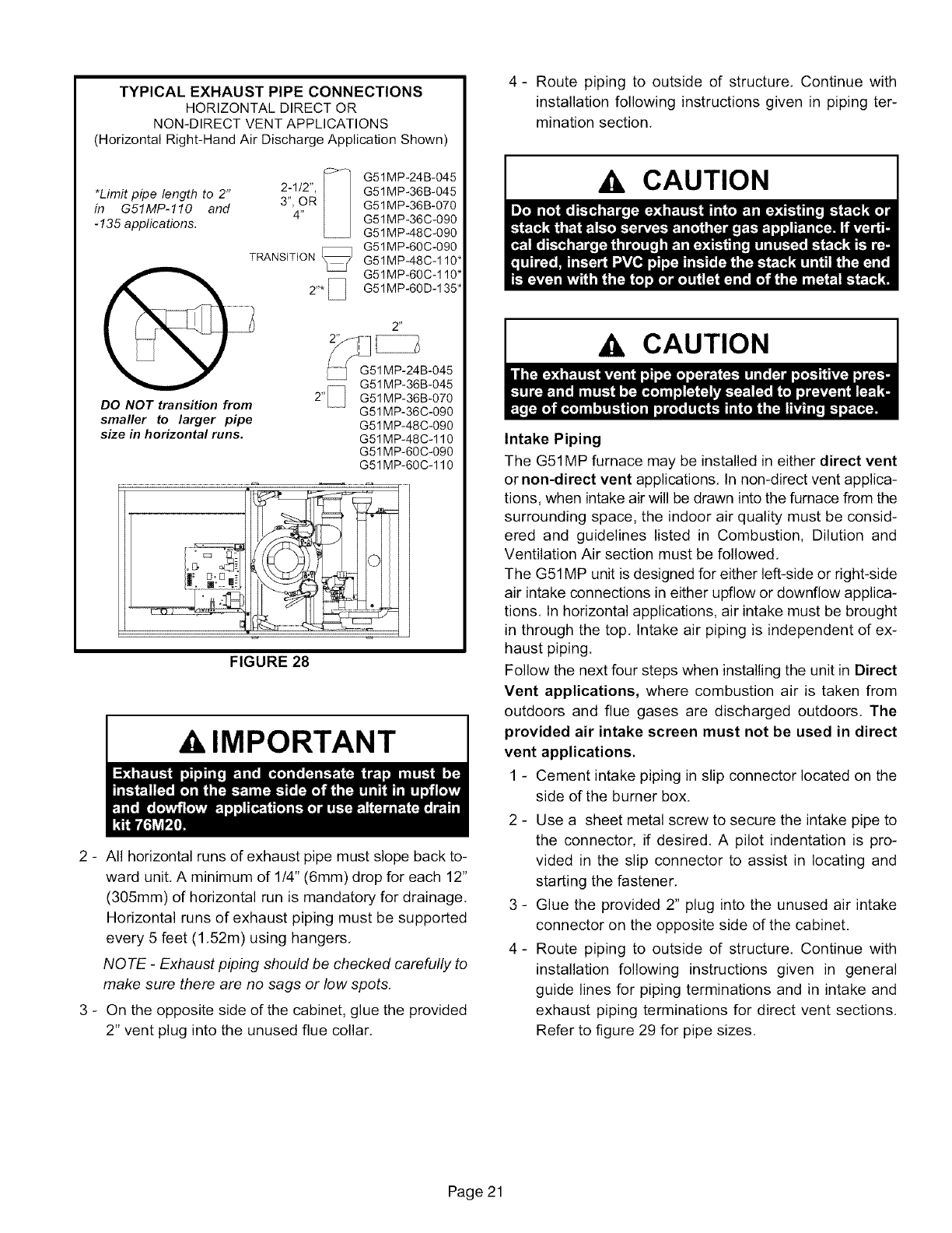
TYPICAL EXHAUST PIPE CONNECTIONS
HORIZONTAL DIRECT OR
NON-DIRECT VENT APPLICATIONS
(Horizontal Right-Hand Air Discharge Application Shown)
*Limit pipe length to 2"
in G51MP-110 and
-135 applications. G51MP-24B-045
2-1/2", G51MP-36B-045
3", OR G51MP-36B-070
4" G51 MP-36C-090
G51MP-48C-090
G51MP-60C-090
TRANSiTiON \/G51MP-48C-110"
G51MP-60C-110"
2"* [] G51MP-60D-135*
DO NOT transition from
smaller to larger pipe
size in horizontal runs.
2 _,
1MP-24B-045
G51MP-36B-045
2" /F G51MP-36B-070
G51 MP-36C-090
G51 MP-48C-090
G51 MP-48C-110
G51MP-60C-090
G51MP-60C-110
FIGURE 28
,&,IMPORTANT
2 - All horizontal runs of exhaust pipe must slope back to-
ward unit. A minimum of 1/4" (6mm) drop for each 12"
(305mm) of horizontal run is mandatory for drainage.
Horizontal runs of exhaust piping must be supported
every 5 feet (1.52m) using hangers.
NOTE -Exhaust piping should be checked carefully to
make sure there are no sags or low spots.
3 - On the opposite side of the cabinet, glue the provided
2" vent plug into the unused flue collar.
4- Route piping to outside of structure, Continue with
installation following instructions given in piping ter-
mination section.
A. CAUTION
,A CAUTION
Intake Piping
The G51MP furnace may be installed in either direct vent
or non-direct vent applications. In non-direct vent applica-
tions, when intake air will be drawn into the furnace from the
surrounding space, the indoor air quality must be consid-
ered and guidelines listed in Combustion, Dilution and
Ventilation Air section must be followed.
The G51MP unit is designed for either left-side or right-side
air intake connections in either upfiow or downfiow applica-
tions. In horizontal applications, air intake must be brought
in through the top. Intake air piping is independent of ex-
haust piping.
Follow the next four steps when installing the unit in Direct
Vent applications, where combustion air is taken from
outdoors and flue gases are discharged outdoors. The
provided air intake screen must not be used in direct
vent applications.
1 - Cement intake piping in slip connector located on the
side of the burner box.
2 - Use a sheet metal screw to secure the intake pipe to
the connector, if desired. A pilot indentation is pro-
vided in the slip connector to assist in locating and
starting the fastener.
3 - Glue the provided 2" plug into the unused air intake
connector on the opposite side of the cabinet.
4- Route piping to outside of structure. Continue with
installation following instructions given in general
guide lines for piping terminations and in intake and
exhaust piping terminations for direct vent sections.
Refer to figure 29 for pipe sizes.
Page 21

TYPICAL AIR INTAKE PIPE CONNECTIONS
UPFLOW OR DOWNFLOW DIRECT VENT APPLICATIONS
(Right-Hand Exit in Upflow Application Shown)
PLUG
(Must be
glued in
place)
©2,_ _ ....................
G51MP-24B-045
G51MP-36B-045
G51MP-36B-070
G51MP-36C-090
G51MP-48C-090
G51MP-48C-110
G51MP-60C-090
G51MP-60C-110
2-1/2", F_
3" OR
4 _
TRANSITION _]_
2'*_
2"*_
G51MP-24B-045
G51MP-36B-045
G51MP-36B-070
G51MP-36c-0g0
G51 MP-48C-090
G51MP-60C-090
G51 MP-48C-110"
G51M P-60C-110"
2-1/2",
3" OR
4'
TRANSITION
2"*X
G51MP-24B-045
G51MP-36B-045
G51MP-36B-070
G51 MP-36C-090
G51 MP-48C-090
G51MP-60C-090
G51 MP-48C-110*
G51MP-60C-110*
G51MP-60D-135*
*Limit pipe length to 2"
in G51MP-110 and -135
applications.
FIGURE 29
TYPICAL AIR INTAKE PIPE CONNECTIONS
HORIZONTAL DIRECT VENT APPLICATIONS
(Horizontal Right-Hand Air Discharge Application Shown)
G51MP-24B-045 __T
G51MP-36B-045
*Limit pipe G51M P-36B-070
length to 2"in G51MP-36C-090
G51MP-110 G51MP-48C-090
G51MP-60C-090
and -135 G51MP-48C-110" TRANSITION
applications. G51 M P-60C- 110*
G51MP-60D-135* _ 2"*
G51 MP-24B-045 2-1/2",
G51MP-36B-045 2"* .........3" OR 4"
G51MP'36B-070 :_q_ TRAN_SlTON " t
G51 MP-36C-090
G51 MP-48C-090 I
G51MP-60C-090
G51MP-48C-110* _ 2'_
G51MP-60C-110"
G51MP-24B-045
G51MP-36B-045
G51MP-36B-070
G51MP-36C-090
G51MP-48C-090
G51MP-48C-110 2" _
G51MP-60C-090
G51MP-60C-110
Follow the next three steps when installing the unit in Non-
Direct Vent applications where combustion air is taken
from indoors and flue gases are discharged outdoors.
TYPICAL AIR INTAKE PIPE CONNECTIONS
UPFLOW OR HORIZONTAL NON-DIRECT
VENT APPLICATIONS
(Right-Hand Exit in Upflow Application Shown)
PLUG
(Must be
glued in
place) INTAKE
DEBRIS
SCREEN
(Provided)
NOTE -Debris screen and elbow may be rotated, so that
screen may be positioned to face forward, backward or
downward.
FIGURE 31
FIGURE 30
Page 22
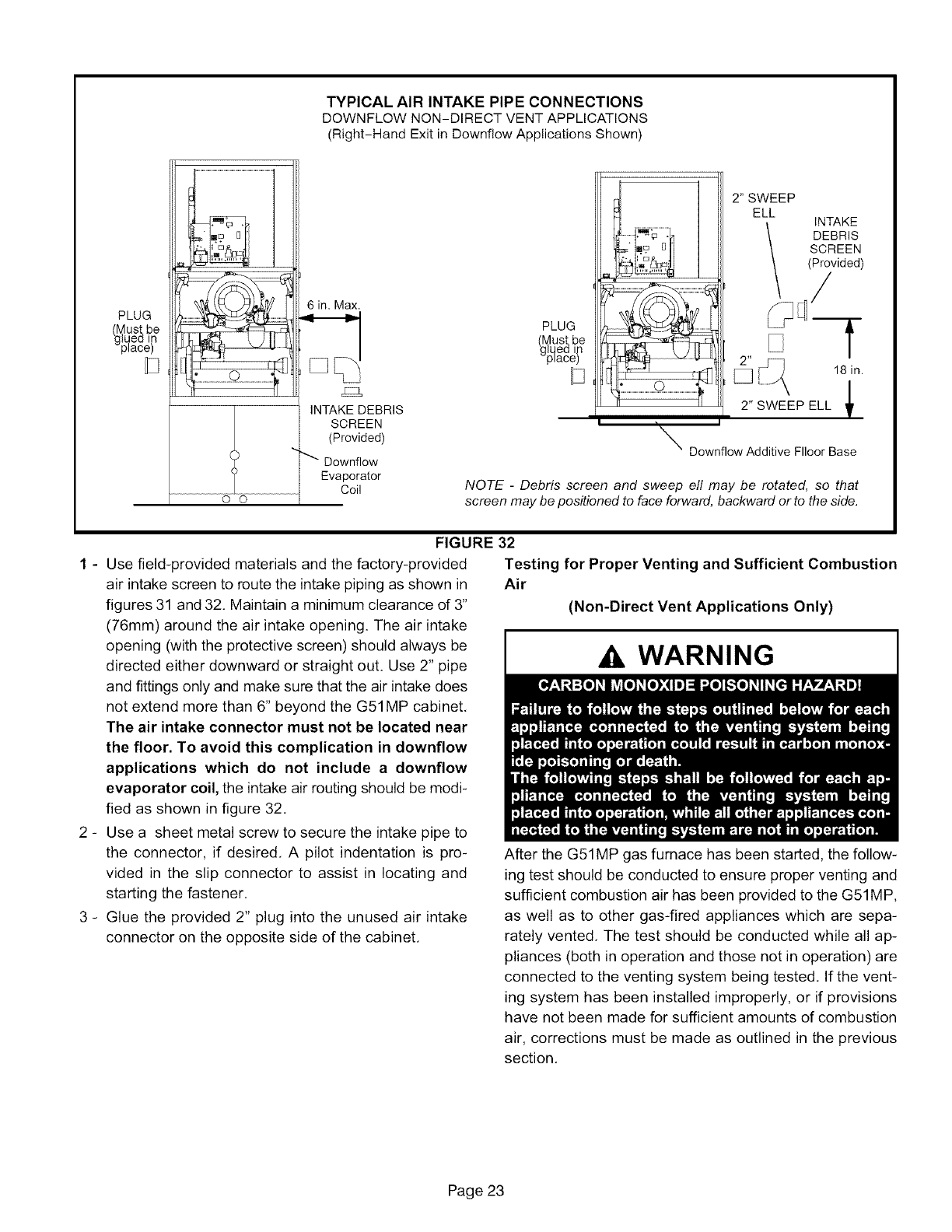
TYPICAL AIR INTAKE PIPE CONNECTIONS
DOWNFLOW NON-DIRECT VENT APPLICATIONS
(Right-Hand Exit in Downfiow Applications Shown)
PLUG
_[_pqUst be
ed tn
lace)
O O
6 in. Max.
2_
INTAKE DEBRIS
SCREEN
(Provided)
Downflow
Evaporator
Coil
PLUG
(gl_ust be
ed t
qaee
2" SWEEP
ELL INTAKE
DEBRIS
SCREEN
(Provided)
/f
Downflow Additive Flloor Base
NOTE -Debris screen and sweep ell may be rotated, so that
screen may be positioned to face forward, backward or to the side.
FIGURE 32
1 - Use field-provided materials and the factory-provided
air intake screen to route the intake piping as shown in
figures 31 and 32, Maintain a minimum clearance of 3"
(76mm) around the air intake opening. The air intake
opening (with the protective screen) should always be
directed either downward or straight out. Use 2" pipe
and fittings only and make sure that the air intake does
not extend more than 6" beyond the G51MP cabinet,
The air intake connector must not be located near
the floor. To avoid this complication in downflow
applications which do not include a downflow
evaporator coil, the intake air routing should be modi-
fied as shown in figure 32,
2 - Use a sheet metal screw to secure the intake pipe to
the connector, if desired, A pilot indentation is pro-
vided in the slip connector to assist in locating and
starting the fastener,
3 - Glue the provided 2" plug into the unused air intake
connector on the opposite side of the cabinet,
Testing for Proper Venting and Sufficient Combustion
Air
(Non-Direct Vent Applications Only)
WARNING
After the G51MP gas furnace has been started, the follow-
ing test should be conducted to ensure proper venting and
sufficient combustion air has been provided to the G51MP,
as well as to other gas-fired appliances which are sepa-
rately vented, The test should be conducted while all ap-
pliances (both in operation and those not in operation) are
connected to the venting system being tested, If the vent-
ing system has been installed improperly, or if provisions
have not been made for sufficient amounts of combustion
air, corrections must be made as outlined in the previous
section,
Page 23
1- Sealanyunusedopeningsintheventingsystem.
2 - Visuallyinspecttheventingsystemforpropersizeand
horizontalpitch.Determinethereisnoblockageorre-
striction,leakage,corrosion,or otherdeficiencies
whichcouldcauseanunsafecondition.
3- Totheextentthatitispractical,closeallbuildingdoors
andwindowsandall doorsbetweenthe spacein
whichtheappliancesconnectedtotheventingsystem
arelocatedandotherspacesofthebuilding.
4 - Closefireplacedampers.
5- Turnonclothesdryersandanyappliancesnotcon-
nectedto theventingsystem.Turnonanyexhaust
fans,suchasrangehoodsandbathroomexhausts,so
theywilloperateatmaximumspeed.Donotoperatea
summerexhaustfan.
6 - Followthelightinginstructionto placetheappliance
beinginspectedintooperation.Adjustthermostatso
appliancewilloperatecontinuously.
7- Usetheflameofmatchorcandletotestforspillageof
fluegasesatthedrafthoodreliefopeningafter5min-
utesofmainburneroperation.
8- If improperventingis observedduringanyof the
abovetests,theventingsystemmustbecorrectedor
sufficientcombustion/make-upairmustbeprovided.
Theventingsystemshouldbere-sizedtoapproach
the minimumsizeas determinedby usingthe ap-
propriatetablesinappendixGinthecurrentstandards
oftheNationalFuelGasCodeANSI-Z223.1/NPFA54
inthe U.S.A.,andtheappropriateNaturalGasand
Propaneappliancesventingsizingtablesinthecur-
rentstandardoftheCSA-B149NaturalGasandPro-
paneInstallationCodesinCanada.
9- Afterdeterminingthateachapplianceremainingcon-
nectedtothecommonventingsystemproperlyvents
whentestedasindicatedinstep3,returndoors,win-
dows,exhaustfans,fireplacedampersandanyother
gas-burningapplianceto theirpreviousconditionof
use.
GeneralGuidelinesfor VentTerminationsfor Non-Di-
rectVentInstallations.
In Non-DirectVentapplications,combustionairis taken
fromindoorsandthefluegasesaredischargedtotheout-
doors.TheG51MPisthenclassifiedasa non-directvent,
CategoryIVgasfurnace.InNon-DirectVentapplications,
theventterminationislimitedbylocalbuildingcodes.Inthe
absenceof localcodes,refertothecurrentNationalFuel
GasCodeANSIZ223-1/NFPA54in U.S.A.,andcurrent
CSA-B149NaturalGasandPropaneInstallationCodesin
Canadafordetails.
Positionterminationendaccordingto locationgiveninfig-
ure33.Inaddition,positionterminationendsoit is free
fromanyobstructionsandabovethelevelof snowaccu-
mulation(whereapplicable).Theterminationshouldbeat
least12inches(305mm)fromanyopeningthroughwhich
flueproductscouldenterthebuilding.
At vent termination,care must be taken to maintain
protectivecoatingsover buildingmaterials(prolonged
exposureto exhaustcondensatecandestroyprotective
coatings).Itisrecommendedthattheexhaustoutletnotbe
locatedwithin6feet(1.8m)of acondensingunitbecause
thecondensatecandamagethepaintedcoating.
NOTE -If winter design temperature is below 32°F (0°C),
exhaust piping should be insulated with 1/2" (13mm), Ar-
maflex or equivalent when run through unheated space.
Do not leave any surface area of exhaust pipe open to out-
side air, exterior exhaust pipe should be insulated with 1/2"
(13mm) Armaflex or equivalent. In extreme cold climate
areas, 3/4" (f9mm) Armaflex or equivalent may be neces-
sary. Insulation on outside runs of exhaust pipe must be
painted or wrapped to protect insulation from deterioration.
Exhaust pipe insulation may not be necessary in some
specific applications.
NOTE -During extremely cold temperatures, below
approximately 20°F (6.7°C), units with long runs of vent
pipe through unconditioned space, even when insulated,
may form ice in the exhaust termination that prevents the
unit from operating properly. Longer run times of at least 5
minutes will alleviate most icing problems. Also, a heating
cable may be installed on exhaust piping and termination to
prevent freeze-ups. Heating cable instaflation kit is avail-
able from Lennox. See Condensate Piping section for part
numbers.
AIMPORTANT
,&IMPORTANT
Page 24

VENT TERMINATION CLEARANCES
FOR INSTALLATIONS IN THE USA AND CANADA*
[] - G51MP VENT TERMINATION
O - AIR INLET OF OTHER APPLIANCE
!
A - Clearance above grade - 12 in, (305mm) minimum,
B - Clearance to window or door that may be opened -
for vent installations in USA -12 in. (305mm) minimum,
for vent installations in Canada - 12 in, (305ram) mini-
mum for appliances _ 100,000 Btuh (30 kW);
36 in. (0.9m) minimum for appliances > 100,000 Btuh (30
kW).
C - Do notposition terminations directly underroofeaves.
D - Clearance to electric meters, gas meters, regulators, and
relief equipment -
for vent installations in USA - 48 in (1219mm) minimum,
for vent installations in Canada - see current edition of
CSA B149 Code.
E - Clearance to non-mechanical air supply inlet or outlet
for vent installations in USA - 48 in. (1219mm) minimum
horizontal and below, 12 in. (305ram) minimum above.
for vent installations in Canada - 12 in. (305mm) mini-
mum for appliances _ 100,000 Btuh (30 kW);
36 in. (0.9m) minimum for appliances > 100,000 Btuh (30
kW).
F - Clearance to mechanical air supply inlet --
for vent installations in USA - 36 in. minimum (914mm}.
G - Clearance to mechanical air supply inlet --
for vent installations in Canada - 72 in. (1829mm) mini-
mum.
H - Do notpoint terminations into recessed areas such as win-
dow wells, stairwells or alcoves.
J - Do not position terminations directly above a walkway.
*Note -
(I) Dimensions are from the current edition of The National Fuel Gas Code - ANSI-Z223.1/NFPA 54 for USA installa-
tions. In Canada, refer to current edition of CSA B149 installation codes. Local codes or regulations may require dif-
ferent clearances.
(11)In Non-Direct Vent installations, combustion air is taken from indoors and the flue gases are discharged to the out-
doors.
FIGURE 33
Page 25

Details of Intake and Exhaust Piping Terminations for
Direct Vent Installations
NOTE -In Direct Vent installations, combustion air is taken
from outdoors and flue gases are discharged to outdoors.
Intake and exhaust pipes may be routed either horizontally
through an outside wall or vertically through the roof. In at-
tic or closet installations, vertical termination through the
roof is preferred, Figures 34 through 42 show typical ter-
minations.
1 - Exhaust and intake exits must be in same pressure
zone, Do not exit one through the roof and one on the
side. Also, do not exit the intake on one side and the
exhaust on another side of the house or structure.
2 - intake and exhaust pipes should be placed as close
together as possible at termination end (refer to il-
lustrations). Maximum separation is 3" (76mm) on roof
terminations and 6" (152mm) on side wall termina-
tions.
3 - if necessary, install a field-provided reducer to adapt
larger vent pipe size to termination pipe size.
4 - On roof terminations, the intake piping should termi-
nate straight down using two 90° elbows (See figure
34).
5 - Exhaust piping must terminate straight out or up as
shown, In rooftop applications, a reducer may be re-
quired on the exhaust piping at the point where it exits
the structure to improve the velocity of exhaust away
from the intake piping. See table 8.
NOTE -Care must be taken to avoid recirculation of
exhaust back into intake pipe.
TABLE 8
EXHAUST PIPE TERMINATION SIZE REDUCTION
G51MP
MODEL Exhaust Pipe Size Termination Pipe Size
045 and 070 2", 2-1/2", 3" or 4" 1-1/2"
090 2", 2-1/2", 3" or4" 2"
110 2", 2-1/2", 3" or4" 2"*
135 3" or4" 2"*
*Approved 3" concentric termination kit terminates with 2-5/8" ID pipe.
Inches(ram)
8" (203) MIN
12" (305) ABOVE
AVERAGE SNOW
ACCUMULATION
3(76) MAX. SIZE TERMINATION
_PIPE PER TABLE 8.
UNCONDITIONED
ATTIC SPACE
112" (13) FOAM
INSULATION IN
UNCONDITIONED
SPACE
3" (76) OR
2" (51) PVC
PROVIDESUPPORT
FORINTAKE AND
EXHAUST LINES
DIRECT VENT ROOF TERMINATION KIT
(15F75 or 44J41)
FIGURE 34
112 (13) ARMAFLEX
INSULATION IN
UNCONDITIONED SPACE
\
iiiiiiiiir...li-
FIELD- _ --i_ t--I-
PROVIDED ...........--._ ["1"
REDUCER MAY
BE REQUIRED
TO ADAPT
LARGER VENT
PIPE SIZE TO li-
TERMINATION
OUTSIDE J
WALL
12 (305) MAX.
112" (13)
' ARMAFLEX
INSULATION
6 (152) SIZE
MAXIMUM TERMINATION
PIPE PER
TABLE 8.
2 (51) PVC
COUPLING
_1
: 8 (203)
MINIMUM
Inches (mm) TOP VIEWWALL RING KIT
(15J74)
FIGURE 35
6 - On field supplied terminations for side wall exits, ex-
haust piping should extend a maximum of 12 inches
(305mm) beyond the outside wall. Intake piping
should be as short as possible, See figure 35,
7 - On field supplied terminations, a minimum separation
distance between the end of the exhaust pipe and the
end of the intake pipe is 8 inches (203mm),
8 - If intake and exhaust piping must be run up a side wall
to position above snow accumulation or other obstruc-
tions, piping must be supported every 3 ft. (.9m) as
shown in figure 26. Refer to figure 38 for proper piping
method. In addition, WTK wall termination kit must be
extended for use in this application. See figure 41.
When exhaust and intake piping must be run up an
outside wall, the exhaust piping must be terminated
with pipe sized per table 8. The intake piping may be
equipped with a 90° elbow turndown. Using turndown
will add 5 feet (1,5m) to the equivalent length of the
pipe.
9 - Based on the recommendation of the manufacturer, a
multiple furnace installation may use a group of up to
four termination kits WTK assembled together hori-
zontally, as shown in figure 40,
Page 26
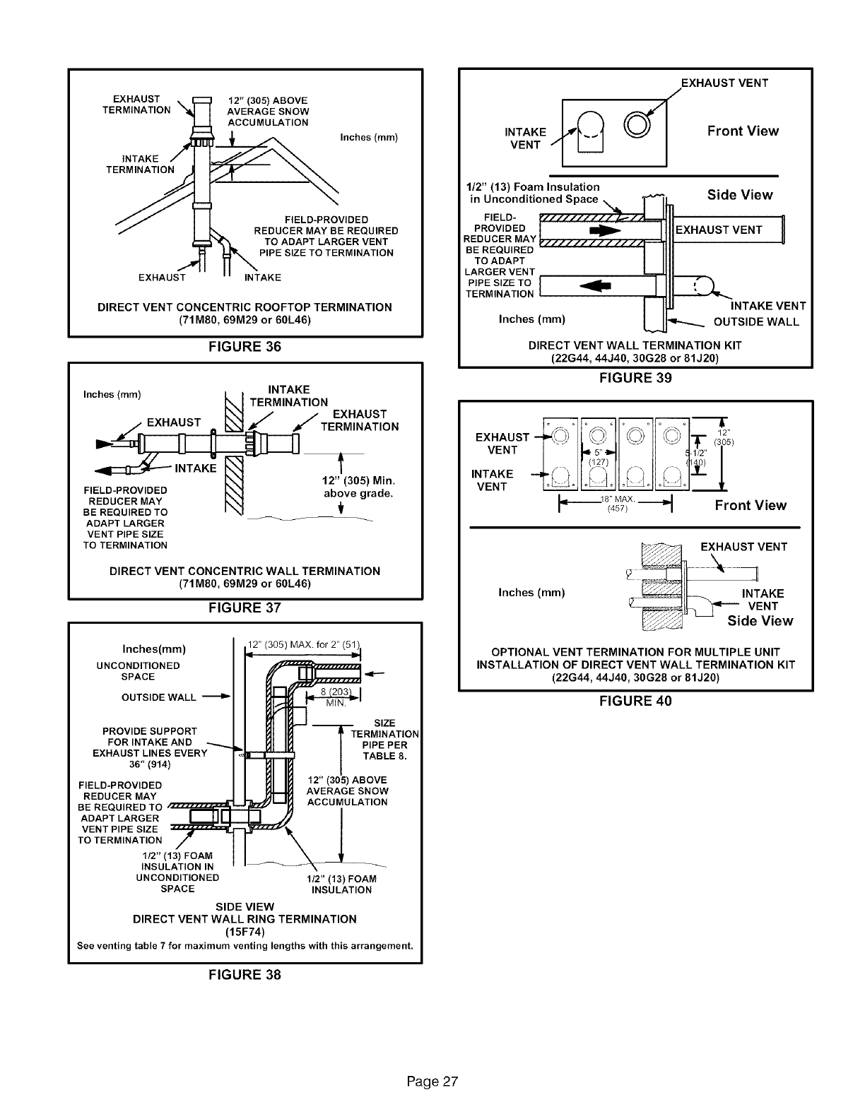
EXHAUST 12" (305) ABOVE
TERMINATION AVERAGE SNOW
ACCUMULATION
INTAKE _ Inches (mm)
TERM____
JJ I I FIELD-PROVIDED
/][',_ REDUCER MAY BE REQUIRED
TO ADAPT LARGER VENT
PIPE SIZE TO TERMINATION
EXHAUST INTAKE
DIRECT VENT CONCENTRIC ROOFTOP TERMINATION
(71M80, 69M29 or 60L46)
FIGURE 36
Inches (mm) INTAKE
TERMINATION
_f E_HAUST
TERMINATION
12" (305) Min.
FIELD-PROVIDED above grade.
REDUCER MAY .L
BE REQUIRED TO •
ADAPT LARGER
VENT PIPE SIZE
TO TERMINATION
DIRECT VENT CONCENTRIC WALL TERMINATION
(71M80, 69M29 or 60L46)
FIGURE 37
Inches(ram) 12" (305) MAX. for 2"
UNCONDITIONED
SPACE
OUTSIDE WALL _ _1
SIZE
PROVIDE SUPPORT TERMINATION
FOR INTAKE AND PIPE PER
EXHAUST LINES EVERY TABLE 8.
36" (914)
FIELD-PROVIDED 12" (305) ABOVE
REDUCER MAY AVERAGE SNOW
ACCUMULATION
BE REQUIRED TO
ADAPT LARGER
VENT PIPE SIZE
TO TERMINATION
t/2 'I (13) FOAM
INSULATION IN
UNCONDITIONED 1/2" (13) FOAM
SPACE INSULATION
SIDE VIEW
DIRECT VENT WALL RING TERMINATION
(15F74)
See venting table 7for maximum venting lengths with this arrangement.
FIGURE 38
EXHAUST VENT
/
INTAKE __'_VENT _ Front View
1/2" (13) Foam Insulation
in Unconditioned Space Side View
PROVIDEDFIELD-
EXHAUST VENT
REDUCER MAY U
BE REQUIRED
TO ADAPT
LARGER VENT
PIPE SIZE TO
TERM NAT ON
INTAKE VENT
Inches (ram) OUTSIDE WALL
DIRECT VENT WALL TERMINATION KIT
(22G44, 44J40, 30G28 or 81J20)
FIGURE 39
)°,° ° o o o o ° ,.
VENT
,NTAKEvENT°
18" MAX.
(4s7/ _ Front View
Inches (ram)
_EXHAUST VENT
,NTAKE
VENT
_,_ -- Side View
OPTIONAL VENT TERMINATION FOR MULTIPLE UNIT
INSTALLATION OF DIRECT VENT WALL TERMINATION KIT
(22G44, 44J40, 30G28 or 81J20)
FIGURE 40
Page 27
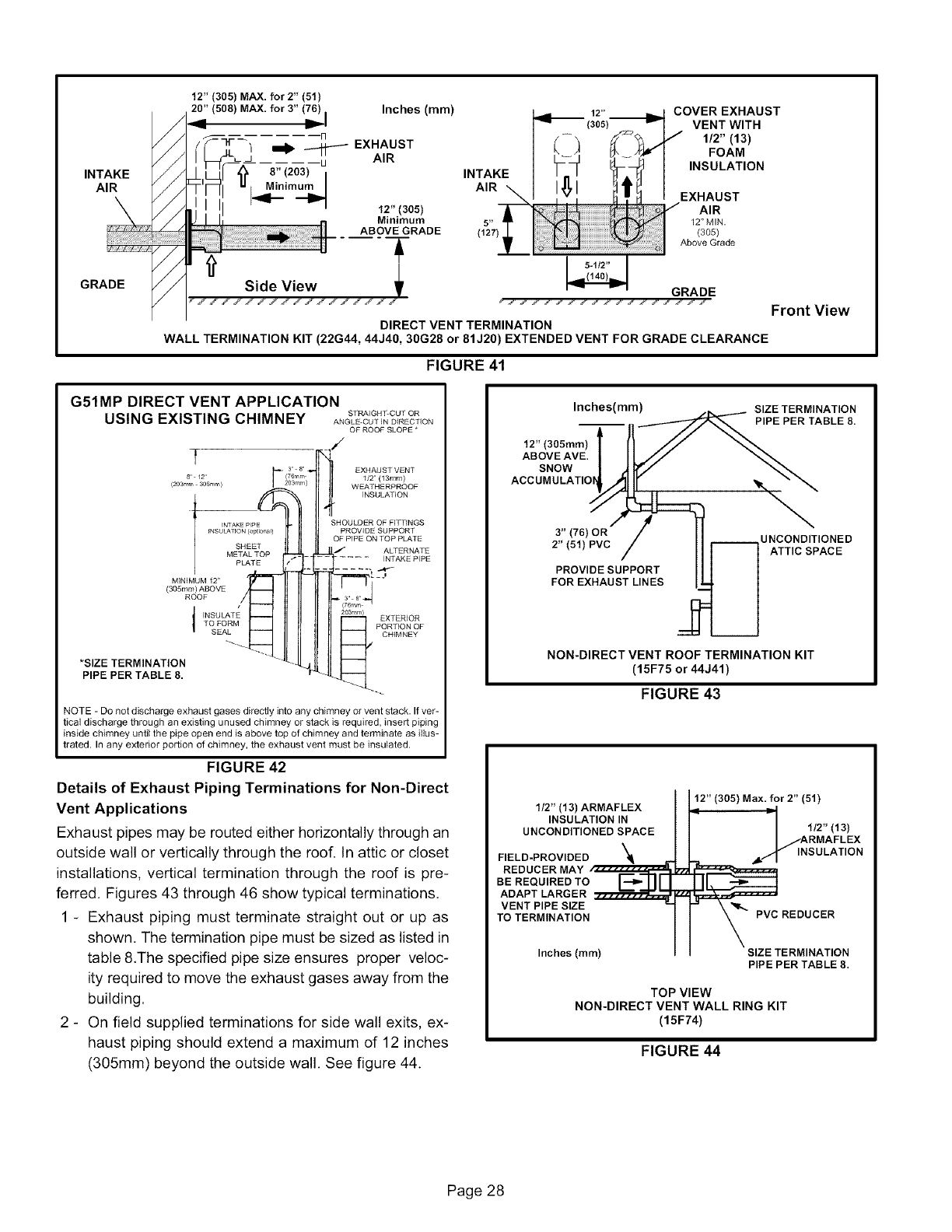
//
/ /
INTAKE / /
AIR //
GRADE
12" (305) MAX. for2" (51)
20" (508) MAX. for3" (L)6) I Inches (ram)
Iw'-,
-Iq x., ust
/1[_[_1_ 8"(203) I
rI_1 " Minimum
i i iI I"=- 12-(305)
J! il
Side View i
1,7 ,f l i ,f l i ,f l i ,f l i ,f l i
12"
(305)
INTAKE
AIR
COVER EXHAUST
VENT WITH
1/2" (13)
FOAM
INSULATION
EXHAUST
AIR
5" 12" MIN.
(127) (305)
Above Grade
GRADE
> f w_f w_f w_f w_f w_f w
DIRECT VENT TERMINATION
WALL TERMINATION KIT (22G44, 44J40, 30G28 or 81J20) EXTENDED VENT FOR GRADE CLEARANCE
Front View
FIGURE 41
G51MP DIRECT VENT APPLICATION
USING EXISTING CHIMNEY ST_IGNT-COTOR
ANGLE_CUT IN DIRECTION
OF ROOF SLOPE *
7EXHAUST VENT
8 12 112" (13ram)
(203rr m 305rr m) WEATHERPROOF
INSULATION
_NTAKEP_PE
fNSULATfON (optioPal)
SHEET
METAL TOP
PLATE
MINIMUM 12"
(305mm) ABOVE
ROOF
*SIZE TERMINATION
PIPE PER TABLE 8.
SHOULDER OF FITTINGS
PROVIDE SUPPORT
OF PIPE ON TOP PLATE
ALTERNATE
INTAKE PIPE
03rrlm) EXTERIOR
P%,7o_oF
"4
NOTE -Do not discharge exhaust gases directly into any chimney or vent stack. If ver-
tical discharge through an existing unused chimney or stack is required, insert piping
inside chimney until the pipe open end is above top of chimney and terminate as illus-
trated. In any exterior portion of chimney, the exhaust vent must be insulated.
FIGURE 42
Details of Exhaust Piping Terminations for Non-Direct
Vent Applications
Exhaust pipes may be routed either horizontally through an
outside wall or vertically through the roof. In attic or closet
installations, vertical termination through the roof is pre-
ferred. Figures 43 through 46 show typical terminations.
1 - Exhaust piping must terminate straight out or up as
shown. The termination pipe must be sized as listed in
table &The specified pipe size ensures proper veloc-
ity required to move the exhaust gases away from the
building.
2 - On field supplied terminations for side wall exits, ex-
haust piping should extend a maximum of 12 inches
(305mm) beyond the outside wall. See figure 44.
Inches(rnrn)
12" (305ram)
ABOVE AVE.
SNOW
ACCUMULATIOI
#
3" (76) OR /
2" (51) PVC /
PROVIDE SUPPORT
FOR EXHAUST LINES
SIZE TERMINATION
PIPE PER TABLE 8.
UNCONDITIONED
ATTIC SPACE
NON-DIRECT VENT ROOF TERMINATION KIT
(15F75 or 44J41)
FIGURE 43
1/2" (13) ARMAFLEX
INSULATION IN
UNCONDITIONED SPACE
FIELD-PROVIDED "_
REDUCER MAY r .........
BE REQUIRED TO I--,--rll i
ADAPT LARGER
VENT PiPE SIZE =-
TO TERMINATION
Inches (mm)
12" (305) Max. for 2" (51)
i
I1/2" (13)
I/ARMAFLEX
,,_'_ INSULATION
k_ PVC REDUCER
SIZE TERMINATION
PiPE PER TABLE 8,
TOP VIEW
NON-DIRECT VENT WALL RING KIT
(15F74)
FIGURE 44
Page 28
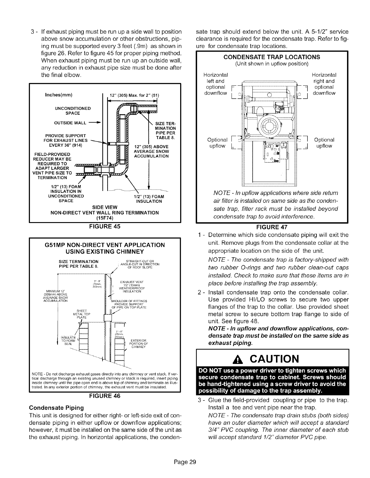
3- Ifexhaustpipingmustberunupasidewalltoposition
abovesnowaccumulationorotherobstructions,pip-
ingmustbesupportedevery3feet(.9m)asshownin
figure26,Refertofigure45forproperpipingmethod.
Whenexhaustpipingmustberunupanoutsidewall,
anyreductioninexhaustpipesizemustbedoneafter
thefinalelbow,
Inches(ram) 12" (305) Max. for2" (51)
UNCONDITIONED
SPACE
OUTSIDE WALL
PROVIDE SUPPORT
FOR EXHAUST LINES
EVERY 30" (914)
FIELD-PROVIDED
REDUCER MAY BE
REQUIRED TO
ADAPT LARGER
VENT PIPE SIZE TO
TERMINATION
SIZE TER-
MINATION
PIPE PER
TABLE 8.
12" (305) ABOVE
AVERAGE SNOW
ACCUMULATION
1/2" (13) FOAM
INSULATION IN
UNCONDITIONED 1/2 l' (13) FOAM
SPACE INSULATION
SIDE VIEW
NON-DIRECT VENT WALL RING TERMINATION
(15F74)
FIGURE 45
G51MP NON-DIRECT VENT APPLICATION
USING EXISTING CHIMNEY
SIZE TERMINATION STRAIGHT-CUT OR
ANGLE-CUT IN DIRECTION
PIPE PER TABLE 8. /OF ROOF SLOPE
EXHAUST VENT
1/2" (13ram)
WEATHERPROOF
INSULATION
SHOULDER OF FITTINGS
PROVIDE SUPPORT
OF PIPE ON TOP PLATE
SHEET F
METAL TOP
PLATE
3 8'
(76mr_
INSOLATE 203rr m)
TO FORM _ EXTERIOR
SEAL __ %T_O_OF
3 8
(76ram
203rnm)
MINIMUM 12"
(305ram) ABOVE
AVERAGE SNOW
ACCUMULATION
NOTE -Do not discharge exhaust gases directly into any chimney or vent stack. If ver-
tica] discharge through an existing unused chimney or stack is required, insert piping
inside chimney until the pipe open end is above top of chimney and terminate as illus-
trated. In any exterior portion of chimney, the exhaust vent must be insu]ated.
FIGURE 46
Condensate Piping
This unit is designed for either right- or left-side exit of con-
densate piping in either upfiow or downfiow applications;
however, it must be installed on the same side of the unit as
the exhaust piping, In horizontal applications, the conden-
sate trap should extend below the unit. A 5-1/2" service
clearance is required for the condensate trap. Refer to fig-
ure for condensate trap locations.
CONDENSATE TRAP LOCATIONS
(Unit shown in upflow position)
Horizontal Horizontal
left and right and
optional _-- _--_] optional
downf!ow LLJ downf!ow
Optional [--_
upflow L_
_ Optional
_ _ upflow
_
_
NOTE -In upflow applications where side return
air filter is installed on same side as the conden-
sate trap, filter rack must be installed beyond
condensate trap to avoid interference.
FIGURE 47
Determine which side condensate piping will exit the
unit. Remove plugs from the condensate collar at the
appropriate location on the side of the unit.
NOTE -The condensate trap is factory-shipped with
two rubber O-rings and two rubber clean-out caps
installed. Check to make sure that these items are in
place before installing the trap assembly.
Install condensate trap onto the condensate collar.
Use provided HI/LO screws to secure two upper
flanges of the trap to the collar, Use provided sheet
metal screw to secure bottom trap flange to side of
unit, See figure 48,
NOTE -In upflow and downflow applications, con-
densate trap must be installed on the same side as
exhaust piping.
CAUTION
3 - Glue the field-provided coupling or pipe to the trap.
Install a tee and vent pipe near the trap.
NOTE -The condensate trap drain stubs (both sides)
have an outer diameter which will accept a standard
3/4" PVC coupling. The inner diameter of each stub
will accept standard 1/2" diameter PVC pipe.
Page 29
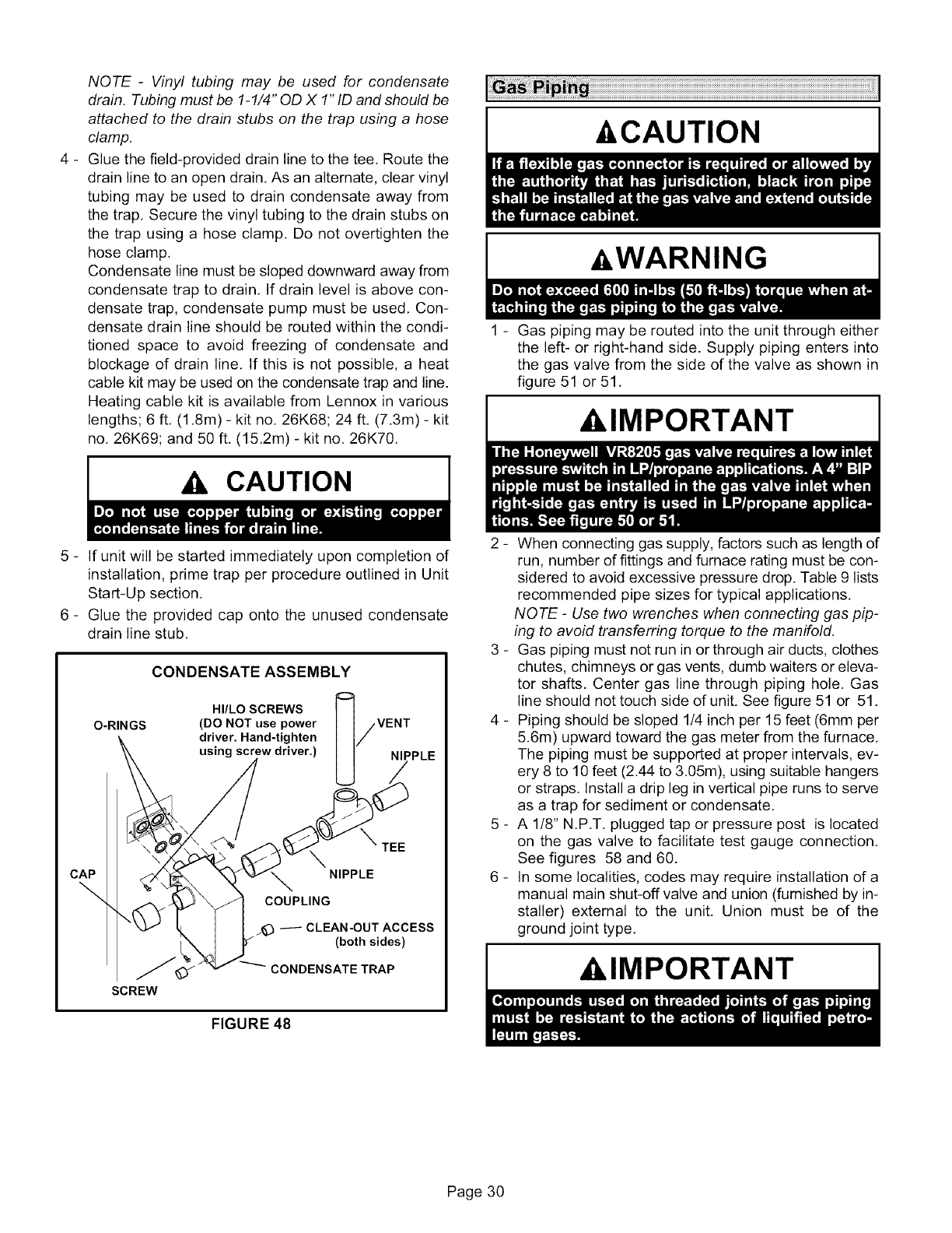
NOTE -Vinyl tubing may be used for condensate
drain. Tubing must be 1-1/4" OD X 1" ID and should be
attached to the drain stubs on the trap using a hose
clamp.
4 - Glue the field-provided drain line to the tee. Route the
drain line to an open drain, As an alternate, clear vinyl
tubing may be used to drain condensate away from
the trap, Secure the vinyl tubing to the drain stubs on
the trap using a hose clamp, Do not overtighten the
hose clamp,
Condensate line must be sloped downward away from
condensate trap to drain, If drain level is above con-
densate trap, condensate pump must be used, Con-
densate drain line should be routed within the condi-
tioned space to avoid freezing of condensate and
blockage of drain line, If this is not possible, a heat
cable kit may be used on the condensate trap and line.
Heating cable kit is available from Lennox in various
lengths; 6 ft, (1.8m) - kit no. 26K68; 24 ft. (7.3m) - kit
no, 26K69; and 50 ft, (15,2m) - kit no, 26K70,
CAUTION
-&CAUTION
_ WARNING
I
1 - Gas piping may be routed into the unit through either
the left- or right-hand side. Supply piping enters into
the gas valve from the side of the valve as shown in
figure 51 or 51.
AIMPORTANT
5 - If unit will be started immediately upon completion of
installation, prime trap per procedure outlined in Unit
Start-Up section.
6 - Glue the provided cap onto the unused condensate
drain line stub.
O-RINGS
CONDENSATE ASSEMBLY
HI/LO SCREWS
(DO NOT use power
driver. Hand-tighten
using screw driver.)
/VENT
NIPPLE
CAP
\
SCREW
_TEE
NIPPLE
COUPLING
_CLEAN-OUT ACCESS
(both sides)
CONDENSATE TRAP
FIGURE 48
2 - When connecting gas supply, factors such as length of
run, number of fittings and furnace rating must be con-
sidered to avoid excessive pressure drop. Table 9 lists
recommended pipe sizes for typical applications.
NOTE -Use two wrenches when connecting gas pip-
ing to avoid transferring torque to the manifold.
3 - Gas piping must not run in or through air ducts, clothes
chutes, chimneys or gas vents, dumb waiters or eleva-
tor shafts. Center gas line through piping hole. Gas
line should not touch side of unit. See figure 51 or 51.
4 - Piping should be sloped 1/4 inch per 15 feet (6mm per
5.6m) upward toward the gas meter from the furnace.
The piping must be supported at proper intervals, ev-
ery 8 to 10 feet (2.44 to 3.05m), using suitable hangers
or straps. Install a drip leg in vertical pipe runs to serve
as a trap for sediment or condensate.
5 - A 1/8" N.P.T. plugged tap or pressure post is located
on the gas valve to facilitate test gauge connection.
See figures 58 and 60.
6 - In some localities, codes may require installation of a
manual main shut-off valve and union (furnished by in-
staller) external to the unit. Union must be of the
ground joint type.
klMPORTANT
Page 30
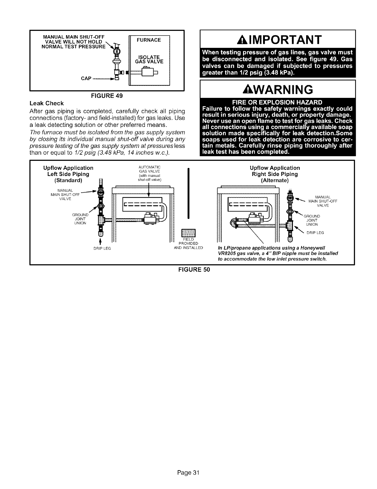
MANUAL MAIN SHUT-OFF
VALVE WILL NOT HOLD FURNACE
ISOLATE
GAS VALVE
FIGURE 49
Leak Check
After gas piping is completed, carefully check all piping
connections (factory- and field-installed) for gas leaks, Use
a leak detecting solution or other preferred means,
The furnace must be isolated from the gas supply system
by closing its individual manual shut-off valve during any
pressure testing of the gas supply system at pressures less
than or equal to 1/2 psig (3.48 kPa, 14 inches w.c.).
XklMPORTANT
&WARNING
Upflow Application AUTOMATIC
GAS VALVE
Left Side Piping (withmanual
(Standard) shut-off valve)
MANUAL
MAIN SHUT-OFF
VALVE
GROUND
JOINT
UNION
,t
DRIP LEG
J
I
FIELD
PROVIDED
AND INSTALLED
Upflow Application
Right Side Piping
(Alternate)
MANUAL
MAIN SHUT-OFF
VALVE
JOINT
UNION
DRIP LEG
In LP/propane applications using a Honeywell
VR8205 gas valve, a 4" BIP nipple must be installed
to accommodate the low inlet pressure switch.
FIGURE 50
Page 31
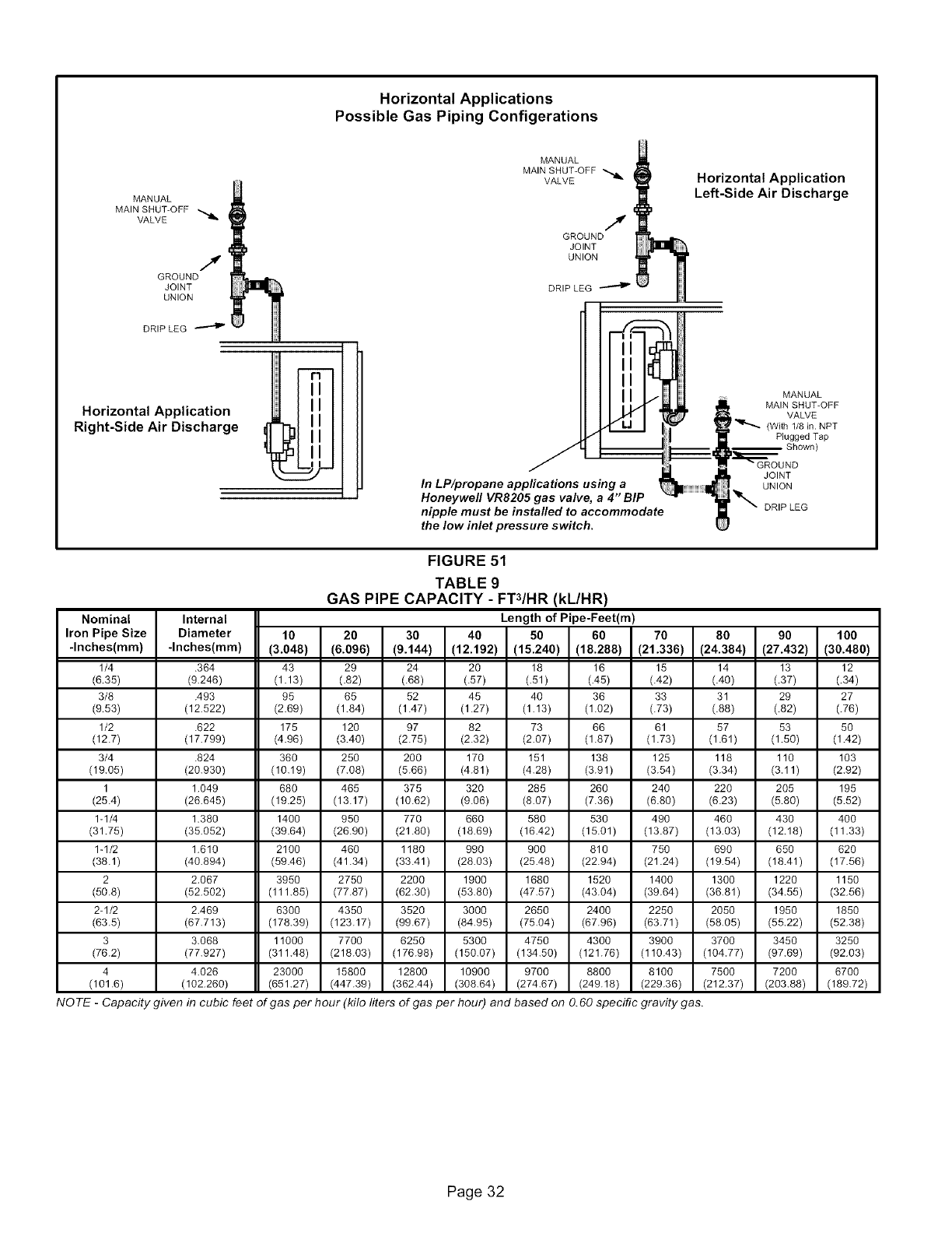
Horizontal Applications
Possible Gas Piping Configerations
MANUAL
MAIN SHUT-OFF
VALVE
J
GROUND
JOINT
UNION
DRIP LEG
Horizontal Application
Right-Side Air Discharge
•-q
LUlII
_31 II
_'-J 2-"
MANUAL
MAIN SHUT-OFF _
VALVE
J
GROUND
JOINT
UNION
DRIP LEG
Horizontal Application
Left-Side Air Discharge
J
In LP/propane appfications using a
Honeywell VR8205 gas valve, a 4" BIP
nipple must be installed to accommodate
the low inlet pressure switch.
MANUAL
MAIN SHUT-OFF
VALVE
(With 1/8 in. NPT
Plugged Tap
Shown)
JOINT
UNION
DRIP LEG
Nominal
Iron Pipe Size
-Inches(ram)
1/4
(6.35)
3/8
(9.53)
1/2
(12.7)
3/4
(19.05)
1
(25.4)
1-1/4
(31.75)
1-1/2
(38.1)
2
(50.8)
2-1/2
(63.5)
3
(76.2)
4
(101.6)
FIGURE 51
TABLE 9
GAS PIPE CAPACITY -FTZ/HR (kL/HR)
Internal Length of Pipe-Feet(m)
Diameter 10 20 30 40 50 60 70
-Inches(ram) (3.048) (6.096) (9.144) (12.192) (15.240) (18.288) (21.336)
,364 43 29 24 20 18 16 15
(9.246) (1.13) (.82) (.66) (.57) (.51) (.45) (.42)
.493 95 65 52 45 40 36 33
(12.522) (2.69) (1.64) (1.47) (1.27) (1.13) (1.02) (.73)
.622 175 120 97 82 73 66 61
(17.799) (4.96) (3.40) (2.75) (2.32) (2.07) (1.67) (1.73)
.824 360 250 200 170 151 138 125
(20.930) (10.19) (7.06) (5.66) (4.61) (4.26) (3.91) (3.54)
1.049 680 465 375 320 265 260 240
(26.645) (19.25) (13.17) (10.62) (9.06) (6.07) (7.36) (6.80)
1,380 1400 950 770 660 580 530 490
(35.052) (39.64) (26.90) (21.60) (16.69) (16.42) (15.01) (13.67)
1.610 2100 460 1180 990 900 810 750
(40.694) (59.46) (41.34) (33.41) (26.03) (25.46) (22.94) (21.24)
2,067 3950 2750 2200 1900 1680 1520 1400
(52.502) (111.65) (77.67) (62.30) (53.60) (47.57) (43.04) (39.64)
2,469 6300 4350 3520 3000 2650 2400 2250
(67.713) (176.39) (123.17) (99.67) (64.95) (75.04) (67.96) (63.71)
3,066 11000 7700 6250 5300 4750 4300 3900
(77.927) (311.48) (216.03) (176.98) (150.07) (134.50) (121.76) (110.43)
4.026 23000 15800 12800 10900 9700 6600 6100
(102.260) (651.27) (447.39) (362.44) (306.64) (274.67) (249.18) (229.36)
8O
(24.384)
14
(.40)
31
(.88)
57
(1.61)
118
(3.34)
22O
(6.23)
46O
(13.03)
69O
(19.54)
1300
(36.81)
2050
(58.05)
3700
(104.77)
7500
(212.37)
NO TE - Capacity given in cubic feet of gas per hour (kilo liters of gas per hour) and based on O.60 specific gravity gas.
9O
(27.432)
13
(.37)
29
(.82)
53
(1.50)
110
(3.11)
205
(5.80)
430
(12.18)
650
(18.41)
1220
(34.55)
1950
(55.22)
3450
(97.69)
7200
(203.88)
100
(30.480)
12
(.34)
27
(.76)
50
(1.42)
103
(2.92)
195
(5.52)
400
(11.33)
620
(17.56)
1150
(32.56)
1850
(52.38)
3250
(92.03)
6700
(189.72)
Page 32

ELECTROSTATIC DISCHARGE (ESD)
Precautions and Procedures
ACAUTION
INTERIOR MAKE-UP BOX INSTALLATION
MAKE-UP
BOX
Right Side
J
8
FIGURE 52
INTERIOR MAKE-UP BOX INSTALLATION
Left side BOX
FIGURE 53
The unit is equipped with a field make-up box. The make-
up box may be moved to the right side of the furnace to fa-
cilitate installation. If the make-up box is moved to the right
side, the excess wire must be pulled into the blower
compartment. Secure the excess wire to the existing harn-
ess to protect it from damage.
Refer to figure 55 for field wiring and figure 57 for schematic
wiring diagram and troubleshooting.
1 - Select circuit protection and wire size according to the
unit nameplate. The power supply wiring must meet
Class I restrictions.
2 - Holes are on both sides of the furnace cabinet to facili-
tate wiring.
3 - Install a separate disconnect switch (protected by ei-
ther fuse or circuit breaker) near the furnace so that
power can be turned off for servicing.
4 - Before connecting the thermostat or the power wiring,
check to make sure the wires will be long enough for
servicing at a later date. Remove the blower access
panel to check the length of the wire.
5- Complete the wiring connections to the equipment.
Use the provided unit wiring diagram and the field wir-
ing diagram shown in figure 55. Use 18-gauge wire or
larger that is suitable for Class II rating for thermostat
connections.
_Electrically ground the unit according to local codes or,
in the absence of local codes, according to the current
National Electric Code (ANSI/NFPA No. 70) for the
USA and current Canadian Electric Code part 1 (CSA
standard C22.1) for Canada. A green ground wire is
provided in the field make-up box.
NOTE -The G51MP furnace contains electronic com-
ponents that are polarity sensitive. Make sure that the
furnace is wired correctly and is properly grounded.
7 - One line voltage "EAC" accessory terminal is provided
on the furnace control board. Any electronic air cleaner
rated up to one amp can be connected to this terminal
with the neutral leg dthe circuit being connected to the
any dthe "NEUTRAL" terminals. See figure 56 for con-
trol board configuration. This terminal is energized
whenever the blower is operating.
8 - One line voltage "HUM" accessory terminal is provided
on the furnace control board. Any humidifier rated up
to one amp can be connected to this terminal with the
neutral leg of the circuit being connected to any of the
"NEUTRAL" terminals. See figure 56 for control board
configuration. This terminal is energized in the heating
mode whenever the combustion air inducer is operat-
ing.
Page 33
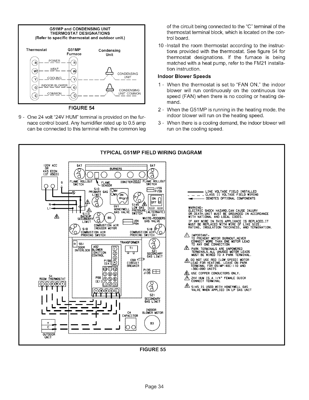
G51MP and CONDENSING UNIT
THERMOSTAT DESIGNATIONS
(Refer to specific thermostat and outdoor unit.)
Thermostat G51MP Condensing
Furnace Unit
@
@
@
'@t POWER
®t HEAT
_-_t COOLING
_--_t INDooRBLoWER
_/ COMMON
CONDENSING
\ UNIT
I_\ CONDENSING
UNIT COMMON
FIGURE 54
9 - One 24 volt "24V HUM" terminal is provided on the fur-
nace control board. Any humidifier rated up to 0.5 amp
can be connected to this terminal with the common leg
of the circuit being connected to the "C" terminal of the
thermostat terminal block, which is located on the con-
trol board.
10-Install the room thermostat according to the instruc-
tions provided with the thermostat. See figure 54 for
thermostat designations. If the furnace is being
matched with a heat pump, refer to the FM21 installa-
tion instruction.
Indoor Blower Speeds
1 - When the thermostat is set to "FAN ON," the indoor
blower will run continuously on the continuous low
speed (FAN) when there is no cooling or heating de-
mand.
2 - When the G51MP is running in the heating mode, the
indoor blower will run on the heating speed.
3 - When there is a cooling demand, the indoor blower will
run on the cooling speed.
TYPICAL G51MP FIELD WIRING DIAGRAM
120V ACC
OR
K45 ECON
(IF USED)
L.
N :
LI_
_x
SI
ROOM THERMOSTAT
F@@@@--01
I1'11
LL -
m
OUTDOOR
UNIT
547 S#7
@ BURNERS
01--I0 000
FLAMESWITCHROLLOUT FLAME SWITCH
--_I_sENS0 R IGNITERRJLR_J FLAME ROLLOU'
JI59
£10 Oav F:_Pi59
_i PRIMARY GAS
iLIMIT O_v/_ /£J N
_< "i LOW GAS {::::3
_ i HONEYWELL --
c,_ _ f"_.GAS VALVE ;_RE(ALTERNATE
....( XDB) sv,
sB_y IHITE-RODGER_
Hu_ [_ij8€ GAS VALVE
/'_ ..... COMBUSTION"--IA_"=;'-IR _P84 ,,_
D-_ ) GIG INDUCER MOTOR SIB (D-ir
\zOyCOMBUSTION AIR COMBUSTION AIR".,/O j
_PROVING SWITCH PROVING SWITCh
INTERLOCK
TRANSFORMER
A92
BLOWER I_
IGNITION _)
CONTROL (_ ODD _'-
PI5_
{E4) [_ CIRCUIT
iBREAKER
7D®@i
PSB_®®i
(EJ}
@
S21
SECONDARY
GAS LIMIT
Z_
PI3S r-r-t
JI3S
@
S2 I
SECONDARY
GAS LIMIT
--- CAP 'ITORMOTOR
@
LINE VOLTAGE FIELD INSTALLED
.... CLASS II VOLTAGE FIELD WIRING
-,,m--DENOTES OPTIONAL COMPONENTS
WARNING-
ELECTRIC SHOCK HAZARD,CAN CAUSE INJURY
OR DEATH.UNIT MUST BE GROUNDED IN ACCORDANCE
WITH NATIONAL AND LOCAL CODES.
IF ANY WIRE IN THIS APPLIANCE IS REPLACED, IT
MUST BE REPLACED WITH WIRE OF LIKE SIZE,
RATING, INSULATION THICKNESS, AND TERMINATION.
/_ IMPORTANT-
TO PREVENT MOTOR BURNOUT,NEVER
CONNECT MORE THAN ONE MOTOR LEAD
TO ANY ONE CONNECTION
./2X PARK TERMINALS ARE UNPOWERED
TERMINALS.ALL UNUSED MOTOR LEADS
MUST BE WIRED TO A PARK TERMINAL.
z_DO NOT USE RED (LOW SPEED) MOTOR
LEAD FOR HEATING. LEAVE ON PARK
TERMINAL FOR GSIMP-48C-IIO AND
-36C-090 UNITS
Z_USE COPPER CONDUCTORS ONLY.
,/_24V HUM IS A I/4" FEMALE QUICK
CONNECT TERMINAL
A
=/-_S145 IS USED WITH HONEYWELL GAS
VALVE WHEN APPLIED IN LP GAS UNIT
FIGURE 55
Page 34
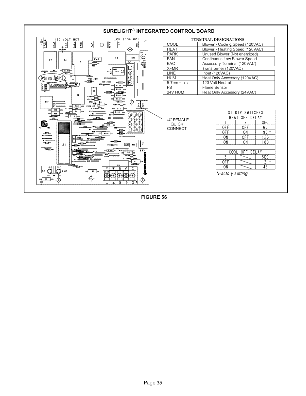
SURELIGHI'ClNTEGRATEDCONTROLBOARD
COOL
HEAT
PARK
FAN
EAC
XFMR
LINE
HUM
5 Terminals
FS
24V HUM
TERMINAL DESIGNATIONS
Blower - Cooling Speed (120VAC)
Blower- Heating Speed (120VAC)
Unused Blower (Not energized)
Continuous Low Blower Speed
Accessory Terminal (120VAC)
Transformer (120VAC)
Input (120VAC)
Heat Only Accessory (120VAC)
120 Volt Neutral
Flame Sensor
Heat Only Accessory (24VAC)
1/4" FEMALE
QUICK
CONNECT
Sl DIP SWITCHES
HEAT OFF DELAY
I 2 SEC
OFF OFF 60
OFF ON 90 *
OH OFF 120
ON ON 180
COOL OFF DELAY
3 _ SEC
OFF _ 2 *
ON _ 45
•Factory settin_
FIGURE 56
Page 35
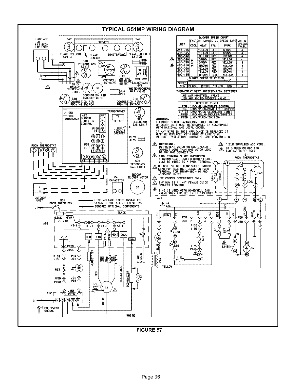
TYPICAL G51MP WIRING DIAGRAM
120V ACC
OR
K¢5 ECON
(IF USED)
L
N I
SI
ROOM THERMOSTAT
It'll
III L
LL ----
OUTDOOR
UNIT $51
DOOR INTERLOCK
BURNERS
Ol-IO 000
FLAME ROLLDUT _ FLAME IGNITER R3LR3_ FLAME ROLLDUT
SWITCH _.. SENSOR SWITCH
SID _ F=_ JI59
PRIMARY GAG Pt59
LIMIT{NV_I _',
_ HONEYWELL pLROEWSgRSE
IIISi_ _ _--..OAS VALVE SWITCH (ALTERNATE1
sE_ACKUPy(J_ Y B6 "_ __ WHITEGVoDGERG
JB4 6AS VALVE
CDMBG_TION AIR _r_
_SI8 INDUCER MOTOR SlB CD_
_CDMBUSTIOR AIR COMBUSTION AIR\/OJ
PROVING SWITCH PRDVING SWITCH
B#o' TRAHSPORMER....
INTERLOCK BLOWER $21
IGNITION SECONDARY
CDNTROL GAS LIMIT
P156 CBB 'I-
(E4)_ CIRCUIT
BREAKER
PISS
JI55 E_
P5B
(Et)
$21
• - i I I SECONDARY
-- -- ,_.¢iiJjI I BAG LIMITINDOORC4 BLOWER MOTOR
ICAPACITOR
LINE VOLTAGE FIELD INSTALLED
.... CLASS II VOLTAGE FIELD WIRING
BLOWI;R SPEED CHART
FACTORY CONNECTED SPEED TAP.c
UNIT [:_.,= H_A= =_AN _ YAH*
2AB'04_._._55 IYELLOW I RED I BRD_
365-0'$5 IYFII _ I RFn IR_
360-DgO _ BROWN H_U I YF..Lt.U*
48C-ODD <_ DROWN RED YELLOW
IYELLOWIRED IBROWN
IYFI I _ I t_Fr) I RRn_
RED YELLLY#
BLOWER SPEED SELECTION
BLACK BROWN YELLOW
THERMOSTAT HEAT ANTICIPATION SETTINGS
JACKPLUG CHART
_B_JA_ CONTROL
IJ.PB4 IJACKIPLUG-COMB.AIR INDUCER
IJ,PI35 IJACK/PLUG-SECDNDARY LIMIT
_PIS_ _ACK/PLUG-INDUCER/IGNITER
,P159 UACK/PLUG-IGNITION
WARNING-
ELECTRIC SHOCK HAZARD,CAN CAUSE INJURY
OR DEATH.UNIT MUST BE GROUNDED IN ACCORDANCE
WITH NATIONAL AND LOCAL CODES.
IF ANY WIRE IN THIS APPLIANCE IS REPLACED,IT
MUST BE REPLACED WITH WIRE OF LIKE SIZE,
RATING, INSULATION THICKNESS, AND TERMINATION.
/_ IMPORTANT- _ FIELD SUPPLIED ACC,WIRE,
TO PREVENT MOTOR BURROUT,NEVER AS113 USED OH DSD, I I0
CONNECT MORE THAN ONE MDTOR LEAD AND 155 UNITS ONLY.
TO ANY ORE CONNECTIDN St
Z_ PARK TERMINALS ARE UNPO_ERED ROOMTHERMOSTAT
TERMINALS,ALL UNUSED MOTOR LEADS
-36C-OR0 UNITS T_I_'I I h Kb I),.,''•1
/_ USE COPPER CONDUCTORS ONLY, _N_I I I --_ "_-_ YI
/_X_H_ _R_IN_" FEMALE QUICK '_ II M _COOL/_z'_ l
IJ
..... tt%
Ll_.e__O _ DENOTES OPTIONAL COMPONENTS
!
A92 LIIz_oEV XFMR " ? _JSB t t_
I,_OVA_ I _ D JSD_ , .
) P_s,F s"s_-/%j__ Qv'_I($)
PIS9jI5g J84 _SEE BLUR _z_ I _="
-- SPEED CHART .Jw _.r_ "'I v-
zc _ YELLOW
R33
_,? ,o, _ - :
ADZF_'N I T I I
(_'EEDUIP.ENTI I I L----..__ __J I
_o_ND I I' :I /
WHITE /
FIGURE 57
Page 36
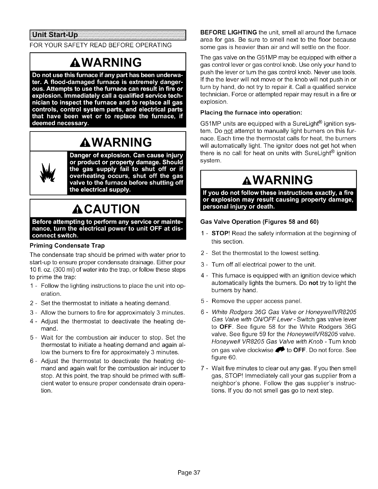
FORYOURSAFETYREADBEFOREOPERATING
_WARNING
,WARNING
,CAUTION
BEFORE LIGHTING the unit, smell all around the furnace
area for gas, Be sure to smell next to the floor because
some gas is heavier than air and will settle on the floor.
The gas valve on the G51MP may be equipped with either a
gas control lever or gas control knob. Use only your hand to
push the lever or turn the gas control knob, Never use tools.
If the the lever will not move or the knob will not push in or
turn by hand, do not try to repair it. Call a qualified service
technician. Force or attempted repair may result in a fire or
explosion.
Placing the furnace into operation:
G51MP units are equipped with a SureLight ¢ ignition sys-
tem, Do not attempt to manually light burners on this fur-
nace. Each time the thermostat calls for heat, the burners
will automatically light. The ignitor does not get hot when
there is no call for heat on units with SureLight ¢ ignition
system,
a,WARNING
Priming Condensate Trap
The condensate trap should be primed with water prior to
start-up to ensure proper condensate drainage. Either pour
10 fl, oz. (300 ml) of water into the trap, or follow these steps
to prime the trap:
1 - Follow the lighting instructions to place the unit into op-
eration,
2 - Set the thermostat to initiate a heating demand.
3 - Allow the burners to fire for approximately 3 minutes,
4- Adjust the thermostat to deactivate the heating de-
mand,
5 - Wait for the combustion air inducer to stop, Set the
thermostat to initiate a heating demand and again al-
low the burners to fire for approximately 3 minutes.
6- Adjust the thermostat to deactivate the heating de-
mand and again wait for the combustion air inducer to
stop. At this point, the trap should be primed with suffi-
cient water to ensure proper condensate drain opera-
tion,
Gas Valve Operation (Figures 58 and 60)
1 - STOP! Read the safety information at the beginning of
this section.
.
3-
4-
Set the thermostat to the lowest setting,
Turn off all electrical power to the unit,
This furnace is equipped with an ignition device which
automatically lights the burners. Do not try to light the
burners by hand,
5 - Remove the upper access panel,
6 - White Rodgers 36G Gas Valve or HoneywellVR8205
Gas Valve with ON/OFF Lever - Switch gas valve lever
to OFF. See figure 58 for the White Rodgers 36G
valve. See figure 59 for the HoneywellVR8205 valve,
Honeywell VR8205 Gas Valve with Knob - Turn knob
on gas valve clockwise _ to OFF. Do not force. See
figure 60,
7 - Wait five minutes to clear out any gas, If you then smell
gas, STOP! Immediately call your gas supplier from a
neighbor's phone. Follow the gas supplier's instruc-
tions. If you do not smell gas go to next step.
Page 37
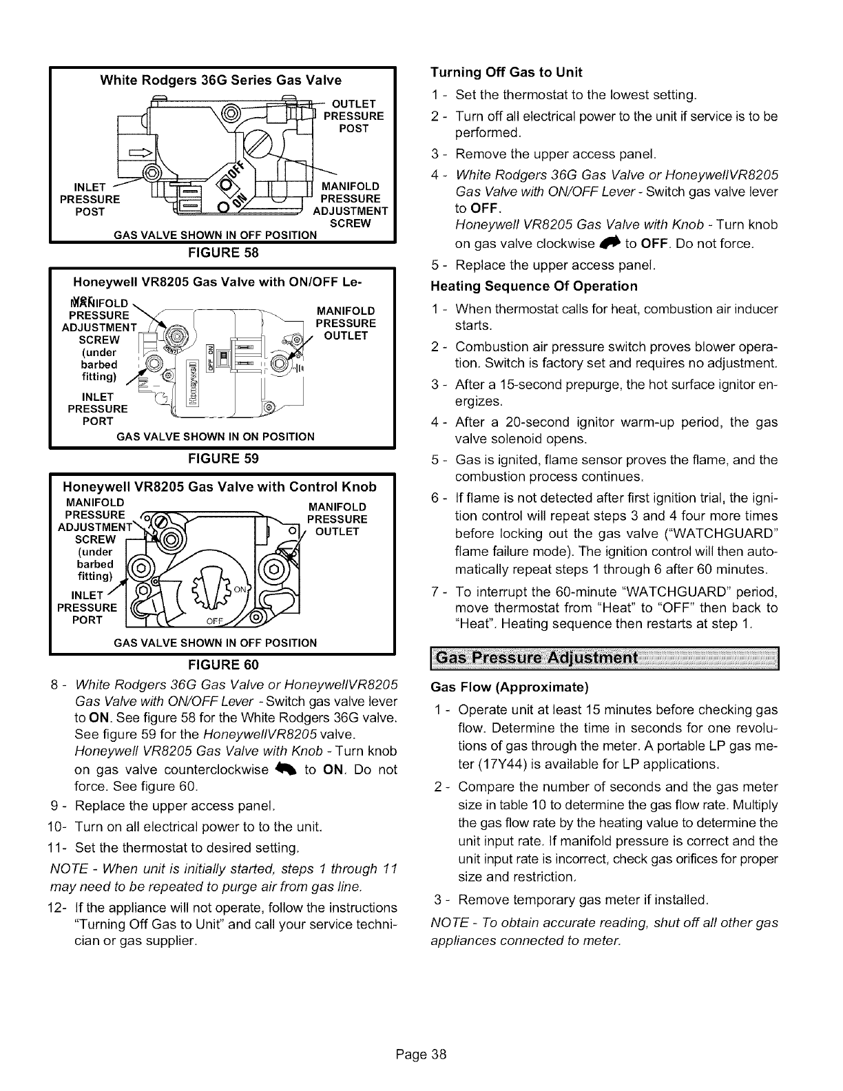
White Rodgers 36G Series Gas Valve
_:::__UTLET
ESSURE
POST
MANIFOLD
INLETI- IIIHr"_q _'>. III I II PRESSURE
PRESSURE _:_ t_v_/'--"_--_ ADJUSTMENT
POST SCREW
GAS VALVE SHOWN IN OFF POSITION
FIGURE 58
Honeywell VR8205 Gas Valve with ON/OFF Le-
I_J_IIFOLD _ r
PRESSURE _,_
ADJUSTMENT_ t
SCREW _
(under _
barbed ,
fitting) /_==_ ._--
INLET _
PRESSURE
PORT
GAS VALVE SHOWN IN ON POSITION
MANIFOLD
PRESSURE
OUTLET
FIGURE 59
Honeywell VR8205 Gas Valve with Control Knob
MANIFOLD
PRESSURE _ _,/
ADJ USTM ENT'_.),._ _ 4_
SCREW
(under I,,'_ ""_ "_
barbedI((o'_/ 1/" _ \
fitting),_!'k_'(_i---, _ _ \
INLET /tL?°N/'
PRESSURE I(,(_(._ " _ -/"
PORT "oF j"/
MANIFOLD
_ _ P(_I_F_UTRE
GAS VALVE SHOWN IN OFF POSITION
FIGURE 60
8 - White Rodgers 36G Gas Valve or HoneyweflVR8205
Gas Valve with ON/OFF Lever - Switch gas valve lever
to ON. See figure 58 for the White Rodgers 36G valve.
See figure 59 for the HoneyweflVR8205 valve.
Honeywell VR8205 Gas Valve with Knob - Turn knob
on gas valve counterclockwise 41_ to ON, Do not
force. See figure 60,
9 - Replace the upper access panel,
10- Turn on all electrical power to to the unit,
11- Set the thermostat to desired setting,
NOTE -When unit is initially started, steps 1 through 11
may need to be repeated to purge air from gas line,
12- If the appliance will not operate, follow the instructions
"Turning Off Gas to Unit" and call your service techni-
cian or gas supplier.
Turning Off Gas to Unit
1 - Set the thermostat to the lowest setting,
2 - Turn off all electrical power to the unit if service is to be
performed,
3 - Remove the upper access panel.
4 - White Rodgers 36G Gas Valve or HoneywellVR8205
Gas Valve with ON/OFF Lever - Switch gas valve lever
to OFF,
Honeywell VR8205 Gas Valve with Knob - Turn knob
on gas valve clockwise _lb to OFF, Do not force,
5 - Replace the upper access panel,
Heating Sequence Of Operation
1-When thermostat calls for heat, combustion air inducer
starts.
2 - Combustion air pressure switch proves blower opera-
tion, Switch is factory set and requires no adjustment,
3 - After a 15-second prepurge, the hot surface ignitor en-
ergizes,
4- After a 20-second ignitor warm-up period, the gas
valve solenoid opens.
5 - Gas is ignited, flame sensor proves the flame, and the
combustion process continues.
6 - If flame is not detected after first ignition trial, the igni-
tion control will repeat steps 3 and 4 four more times
before locking out the gas valve ("WATCHGUARD"
flame failure mode), The ignition control will then auto-
matically repeat steps 1 through 6 after 60 minutes,
7 - To interrupt the 60-minute "WATCHGUARD" period,
move thermostat from "Heat" to "OFF" then back to
"Heat", Heating sequence then restarts at step 1,
Gas Flow (Approximate)
1 - Operate unit at least 15 minutes before checking gas
flow. Determine the time in seconds for one revolu-
tions of gas through the meter, A portable LP gas me-
ter (17Y44) is available for LP applications,
2 - Compare the number of seconds and the gas meter
size in table 10 to determine the gas flow rate. Multiply
the gas flow rate by the heating value to determine the
unit input rate, If manifold pressure is correct and the
unit input rate is incorrect, check gas orifices for proper
size and restriction,
3 - Remove temporary gas meter if installed,
NOTE -To obtain accurate reading, shut off all other gas
appliances connected to meter,
Page 38
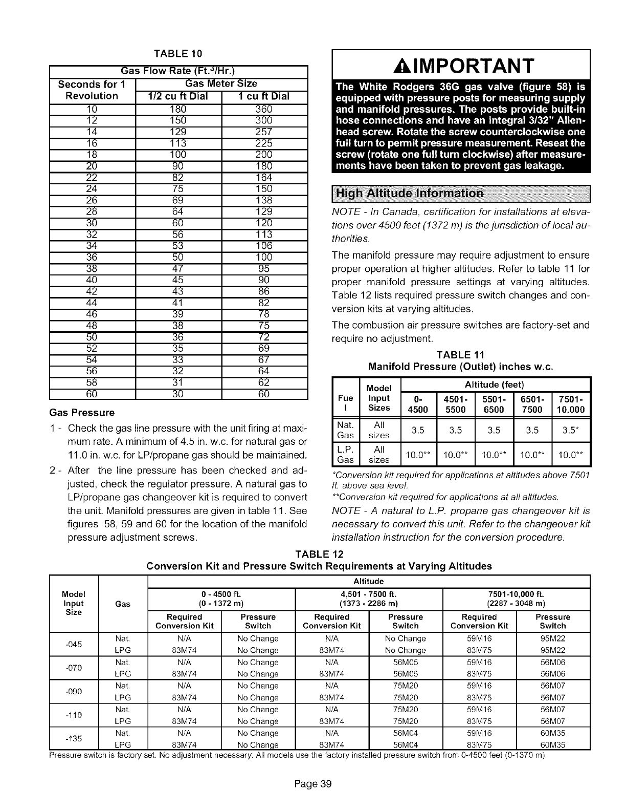
TABLE 10
Gas Flow Rate (Ft._/Hr.)
Seconds for 1
Revolution
10
12
14
16
18
2O
22
24
26
28
3O
32
34
36
38
40
42
44
46
48
5O
52
54
56
58
6O
Gas Meter Size
1/2 cu ft Dial 1 cu ft
18O
15O
129
113
100
90
82
75
69
64
6O
56
53
5O
47
45
43
41
39
38
36
35
33
32
31
3O
Dial
36O
3OO
257
225
2OO
180
164
15O
138
129
120
113
1O6
100
95
90
86
82
78
75
72
69
67
64
62
6O
Gas Pressure
1 - Check the gas line pressure with the unit firing at maxi-
mum rate. A minimum of 4.5 in, w,c. for natural gas or
11,0 in, w,c, for LP/propane gas should be maintained,
2- After the line pressure has been checked and ad-
justed, check the regulator pressure. A natural gas to
LP/propane gas changeover kit is required to convert
the unit, Manifold pressures are given in table 11, See
figures 58, 59 and 60 for the location of the manifold
pressure adjustment screws,
XI,IMPORTANT
NOTE -In Canada, certification for installations at eleva-
tions over 4500 feet (1372 m) is the jurisdiction of local au-
thorities.
The manifold pressure may require adjustment to ensure
proper operation at higher altitudes. Refer to table 11 for
proper manifold pressure settings at varying altitudes.
Table 12 lists required pressure switch changes and con-
version kits at varying altitudes.
The combustion air pressure switches are factory-set and
require no adjustment.
TABLE 11
Manifold Pressure (Outlet) inches w.c.
Model Altitude (feet)
Fue Input 0- 4501- 5501- 6501- 7501-
I Sizes 4500 5500 6500 7500 10,000
Nat. All 3.5 3.5 3.5 3.5 3.5*
Gas sizes
L.P. All 10.0"* 10.0"* 10.0"* 10.0"* 10.0"*
Gas sizes
*Conversion kit required for appfications at altitudes above 7501
ft. above sea level.
**Conversion kit required for appfications at aft altitudes.
NOTE -A natural to L.P. propane gas changeover kit is
necessary to convert this unit. Refer to the changeover kit
installation instruction for the conversion procedure.
Model
Input
Size
-O45
-070
-090
-110
-135
Gas
Nat,
LPG
Nat.
LPG
Nat.
LPG
Nat.
LPG
Nat.
LPG
TABLE 12
Conversion Kit and Pressure Switch Requirements at Varying Altitudes
Altitude
0 - 4500 ft.
(0 - 1372 m)
Required
Conversion Kit
N/A
83M74
N/A
83M74
N/A No
83M74 No
N/A No
83M74 No
Pressure
Switch
No Change
No Change
No Change
No Change
Change
Change
Change
Change
N/A No Change
83M74 No Change
4,501 -7500 ft.
(1373-2286 m)
Required
Conversion Kit
N/A
83M74
N/A
83M74
N/A
83M74
N/A
83M74
N/A
83M74
Pressure
Switch
No Change
No Change
56M05
56M05
75M20
75M20
75M20
75M20
56M04
56M04
7501-10,000 ft.
(2287-3048 m)
Required
Conversion Kit
59M16
83M75
59M16
83M75
59M16
83M75
59M16
83M75
59M16
83M75
Pressure
Switch
95M22
95M22
56M06
56M06
56M07
56M07
56M07
56M07
60M35
60M35
Pressure switch is factory set, No adjustment necessary. All models use the factory installed pressure switch from 0-4500 feet (0-1370 m).
Page 39
Primary and Secondary Limits
The primary limit is located on the heating compartment
vestibule panel, The secondary limits are located in the
blower compartment, attached to the back side of the blow-
er, These limits are factory set and require no adjustment,
Flame Rollout Switches (Two)
These manually reset switches are located on the burner
box. If tripped, check for adequate combustion air before
resetting,
Pressure Switches (Two)
The pressure switches are located in the heating compart-
ment on the combustion air inducer, These switches check
for proper combustion air inducer operation before allow-
ing ignition trial, The switches are factory-set and require
no adjustment.
Temperature Rise
After the furnace has been started and supply and return
air temperatures have been allowed to stabilize, check the
temperature rise. If necessary, adjust the blower speed to
maintain the temperature rise within the range shown on
the unit nameplate, Increase the blower speed to decrease
the temperature. Decrease the blower speed to increase
the temperature rise. Failure to adjust the temperature rise
may cause erratic limit operation,
Fan Control
Heating Mode -- The fan on delay of 45 seconds is not ad-
justable. The fan off delay (amount of time that the blower
operates after the heat demand has been satisfied) may be
adjusted by setting $1 switches 1 and 2 located on the
SureLight e control. The unit is shipped with a factory fan off
setting of 90 seconds. The fan off delay affects comfort and
is adjustable to satisfy individual applications. Adjust the
fan off delay to achieve a supply air temperature between
90° and 110°F at the exact moment that the blower is de-
energized. Longer off delay settings provide lower return
air temperatures; shorter settings provide higher return air
temperatures. See figure 56.
Cooling Mode -- The cooling mode fan off delay (amount
of time that the blower operates after the cooling demand
has been satisfied) may be adjusted by setting $1 switch 3
located on the SureLight @control. In the off position, the
cooling fan off delay is 2 seconds. In the on position, the
cooling fan off delay is 45 seconds. See figure 56,
Thermostat Heat Anticipation
Set the heat anticipator setting (if adjustable) according to
the amp draw listed on the wiring diagram that is attached
to the unit.
Electrical
1 - Check all wiring for loose connections,
2 - Check for the correct voltage at the furnace (furnace
operating).
3 - Check amp-draw on the blower motor.
Motor Nameplate Actual
NOTE -Do not secure the electrical conduit directly to the
air ducts or structure,
Blower Speeds
NOTE -CFM readings are taken external to unit with a dry
evaporator coil and without accessories,
1 - Turn off electrical power to furnace,
2 - Remove blower access panel,
3 - Disconnect existing speed tap at control board speed
terminal.
NO TE -Termination of any unused motor leads must be in-
sulated.
4 - Refer to blower speed selection chart on unit wiring
diagram for desired heating or cooling speed,
5- Connect selected speed tap at control board speed
terminal.
6 - Resecure blower access panel.
7 - Turn on electrical power to furnace,
Electronic Ignition
The SureLight ® integrated control has an added feature of
an internal Watchguard control, The feature serves as an
automatic reset device for ignition control lockout caused
by ignition failure. This type of lockout is usually due to low
gas line pressure, After one hour of continuous thermostat
demand for heat, the Watchguard will break and remake
thermostat demand to the furnace and automatically reset
the control to begin the ignition sequence,
Exhaust and Air Intake Pipe
1 - Check exhaust and air intake connections for tightness
and to make sure there is no blockage,
2- Are pressure switches closed? Obstructed exhaust
pipe will cause unit to shut off at pressure switches,
Check termination for blockages,
3- Reset manual flame rollout switches on burner box
cover.
Failure To Operate
If the unit fails to operate, check the following:
1 - Is the thermostat calling for heat?
2 - Are access panels securely in place?
3 - Is the main disconnect switch closed?
4 - Is there a blown fuse?
5 - Is the filter dirty or plugged? Dirty or plugged filters will
cause the limit control to shut the unit off,
6 - Is gas turned on at the meter?
7 - Is the manual main shut-off valve open?
8 - Is the internal manual shut-off valve open?
9 - Is the unit ignition system in lock out? If the unit locks
out again, call the service technician to inspect the unit
for blockages,
Page 40
,&WARNING
At the beginning of each heating season, system should be
checked as follows by a qualified service technician:
Blower
Check the blower wheel for debris and clean if necessary.
The blower motors are prelubricated for extended bearing
life, No further lubrication is needed,
AWARNING
Filters
All G51MP filters are installed external to the unit. Filters
should be inspected monthly. Clean or replace the filters
when necessary to ensure proper furnace operation. Table
3 lists recommended filter sizes,
Exhaust and air intake pipes
Check the exhaust and air intake pipes and all connections
for tightness and to make sure there is no blockage,
Electrical
1 - Check all wiring for loose connections.
2 - Check for the correct voltage at the furnace (furnace
operating),
3 - Check amp-draw on the blower motor.
Motor Nameplate Actual
Winterizing and Condensate Trap Care
1 - Turn off power to the unit,
2 - Have a shallow pan ready to empty condensate water.
3 - Remove the drain plug from the condensate trap and
empty water, Inspect the trap then reinstall the drain
plug,
Cleaning Heat Exchanger
If cleaning the heat exchanger becomes necessary, follow
the below procedures and refer to figure 1 when disassem-
bling unit. Use papers or protective covering in front of fur-
nace while removing heat exchanger assembly.
1 - Turn off electrical and gas supplies to the furnace.
2 - Remove the upper and lower furnace access panels,
3 - Mark all gas valve wires and disconnect them from
valve.
4 - Remove gas supply line connected to gas valve, Re-
move gas valve/manifold assembly.
5 - Remove sensor wire from sensor, Disconnect 2-pin or
3-pin plug from the ignitor.
6 - Disconnect wires from flame roll-out switches.
7 - Remove burner box cover and remove four burner box
screws at the vestibule panel and remove burner box,
Set burner box assembly aside.
NOTE -If necessary, clean burners at this time, Follow
procedures outlined in Burner Cleaning section.
8 - Loosen three clamps and remove flexible exhaust tee,
9 - Remove 3/8 inch rubber cap from condensate drain
plug and drain, Replace cap after draining.
10 - Disconnect condensate drain line from the conden-
sate trap, Remove condensate trap (it may be neces-
sary to cut drain pipe), Remove screws that secure
condensate collars to either side of the furnace and re-
move collars. Remove drain tubes from cold end
header collector box,
11 - Disconnect condensate drain tubing from flue collar,
Remove screws that secure both flue collars into
place. Remove flue collars, It may be necessary to cut
the exiting exhaust pipe for removal of the fittings,
12 - Disconnect the 2-pin plug from the combustion air in-
ducer, Disconnect the two wires to the secondary limit,
if applicable. Remove four screws which secure com-
bustion air inducer to collector box Remove combus-
tion air inducer assembly, Remove ground wire from
vest panel,
13 - Mark and disconnect all combustion air pressure tub-
ing from cold end header collector box.
14 - Mark and remove wires from pressure switches. Re-
move pressure switches, Keep tubing attached to
pressure switches.
15 - Remove electrical junction box from the side of the fur-
nace,
16 - Mark and disconnect any remaining wiring to heating
compartment components. Disengage strain relief
bushing and pull wiring and bushing through the hole
in the blower deck.
17 - Remove the primary limit from the vestibule panel,
18 - Remove two screws from the front cabinet flange at
the blower deck. Spread cabinet sides slightly to allow
clearance for removal of heat exchanger,
Page 41
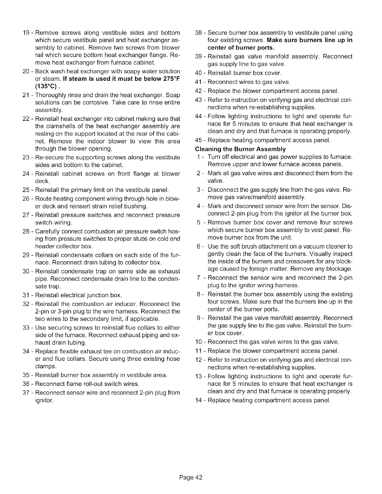
19- Removescrewsalongvestibulesidesand bottom
whichsecurevestibulepanelandheatexchangeras-
semblyto cabinet.Removetwoscrewsfromblower
railwhichsecurebottomheatexchangerflange,Re-
moveheatexchangerfromfurnacecabinet,
20- Backwashheatexchangerwithsoapywatersolution
orsteam,If steamis usedit mustbebelow275°F
(135°C).
21 - Thoroughly rinse and drain the heat exchanger. Soap
solutions can be corrosive, Take care to rinse entire
assembly.
22 - Reinstall heat exchanger into cabinet making sure that
the clamshells of the heat exchanger assembly are
resting on the support located at the rear of the cabi-
net. Remove the indoor blower to view this area
through the blower opening,
23 - Re-secure the supporting screws along the vestibule
sides and bottom to the cabinet,
24- Reinstall cabinet screws on front flange at blower
deck.
25 - Reinstall the primary limit on the vestibule panel.
26 - Route heating component wiring through hole in blow-
er deck and reinsert strain relief bushing.
27 - Reinstall pressure switches and reconnect pressure
switch wiring.
28 - Carefully connect combustion air pressure switch hos-
ing from pressure switches to proper stubs on cold end
header collector box,
29 - Reinstall condensate collars on each side of the fur-
nace. Reconnect drain tubing to collector box,
30 - Reinstall condensate trap on same side as exhaust
pipe. Reconnect condensate drain line to the conden-
sate trap.
31 - Reinstall electrical junction box.
32 - Reinstall the combustion air inducer. Reconnect the
2-pin or 3-pin plug to the wire harness, Reconnect the
two wires to the secondary limit, if applicable,
33 - Use securing screws to reinstall flue collars to either
side of the furnace. Reconnect exhaust piping and ex-
haust drain tubing,
34 - Replace flexible exhaust tee on combustion air induc-
er and flue collars, Secure using three existing hose
clamps,
35 - Reinstall burner box assembly in vestibule area,
36 - Reconnect flame roll-out switch wires,
37 - Reconnect sensor wire and reconnect 2-pin plug from
ignitor,
38 - Secure burner box assembly to vestibule panel using
four existing screws. Make sure burners line up in
center of burner ports.
39- Reinstall gas valve manifold assembly, Reconnect
gas supply line to gas valve,
40 - Reinstall burner box cover,
41 - Reconnect wires to gas valve,
42 - Replace the blower compartment access panel.
43 - Refer to instruction on verifying gas and electrical con-
nections when re-establishing supplies.
44 - Follow lighting instructions to light and operate fur-
nace for 5 minutes to ensure that heat exchanger is
clean and dry and that furnace is operating properly,
45 - Replace heating compartment access panel,
Cleaning the Burner Assembly
1 - Turn off electrical and gas power supplies to furnace.
Remove upper and lower furnace access panels,
2 - Mark all gas valve wires and disconnect them from the
valve.
3 - Disconnect the gas supply line from the gas valve, Re-
move gas valve/manifold assembly.
4 - Mark and disconnect sensor wire from the sensor. Dis-
connect 2-pin plug from the ignitor at the burner box.
5 - Remove burner box cover and remove four screws
which secure burner box assembly to vest panel, Re-
move burner box from the unit,
6 - Use the soft brush attachment on a vacuum cleaner to
gently clean the face of the burners, Visually inspect
the inside of the burners and crossovers for any block-
age caused by foreign matter, Remove any blockage,
7 - Reconnect the sensor wire and reconnect the 2-pin
plug to the ignitor wiring harness.
8 - Reinstall the burner box assembly using the existing
four screws. Make sure that the burners line up in the
center of the burner ports.
9 - Reinstall the gas valve manifold assembly, Reconnect
the gas supply line to the gas valve, Reinstall the burn-
er box cover,
10 - Reconnect the gas valve wires to the gas valve.
11 - Replace the blower compartment access panel,
12 - Refer to instruction on verifying gas and electrical con-
nections when re-establishing supplies.
13- Follow lighting instructions to light and operate fur-
nace for 5 minutes to ensure that heat exchanger is
clean and dry and that furnace is operating properly,
14 - Replace heating compartment access panel,
Page 42
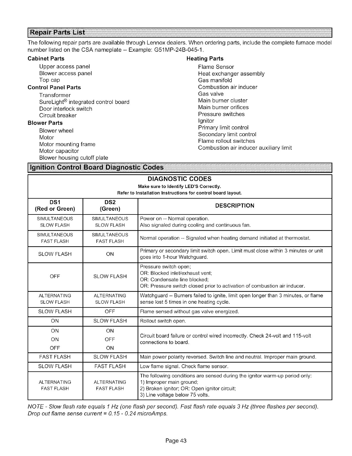
ThefollowingrepairpartsareavailablethroughLennoxdealers.Whenorderingparts,includethecompletefurnacemodel
numberlistedontheCSAnameplate-- Example:G51MP-24B-045-1.
CabinetParts
Upperaccesspanel
Bloweraccesspanel
Topcap
ControlPanelParts
Transformer
SureLight_ integratedcontrolboard
Doorinterlockswitch
Circuitbreaker
Blower Parts
Blower wheel
Motor
Motor mounting frame
Motor capacitor
Blower housing cutoff plate
Heating Parts
Flame Sensor
Heat exchanger assembly
Gas manifold
Combustion air inducer
Gas valve
Main burner cluster
Main burner orifices
Pressure switches
Ignitor
Primary limit control
Secondary limit control
Flame rollout switches
Combustion air inducer auxiliary limit
DIAGNOSTIC CODES
Make sure to Identify LED'S Correctly.
Refer to Installation Instructions for control board layout.
DS1 DS2
(Red or Green) (Green) DESCRIPTION
SIMULTANEOUS SIMULTANEOUS Power on -- Normal operation.
SLOWFLASH SLOWFLASH Also signaled during cooling and continuous fan.
SIMULTANEOUS SIMULTANEOUS Normal operation -- Signaled when heating demand initiated at thermostat.
FAST FLASH FAST FLASH
SLOW FLASH ON Primary or secondary limit switch open. Limit must close within 3 minutes or unit
goes into 1-hourWatchguard.
Pressure switch open;
OFF SLOW FLASH OR: Blocked inlet/exhaust vent;
OR: Condensate line blocked;
OR: Pressure switch closed prior to activation of combustion air inducer.
ALTERNATING ALTERNATING Watchguard -- Burners failed to ignite, limit open longer than 3 minutes, or flame
SLOWFLASH SLOWFLASH sense lost 5 times in one heating cycle.
SLOW FLASH OFF Flame sensed without gas valve energized.
ON SLOW FLASH Rollout switch open.
ON ON Circuit board failure or control wired incorrectly. Check 24-volt and 115-volt
ON OFF connections to board.
OFF ON
FAST FLASH SLOW FLASH Main power polarity reversed. Switchline and neutral. Improper main ground.
SLOW FLASH FAST FLASH Low flame signal. Check flame sensor.
The following conditions are sensed during the ignitor warm-up period only:
ALTERNATING ALTERNATING 1) Improper main ground;
FASTFLASH FASTFLASH 2) Broken ignitor; OR: Open ignitor circuit;
3) Line voltage below 75 volts.
NOTE -Slow flash rate equals 1 Hz (one flash per second). Fast flash rate equals 3 Hz (three flashes per second).
Drop out flame sense current =O.15 -0.24 microAmps.
Page 43
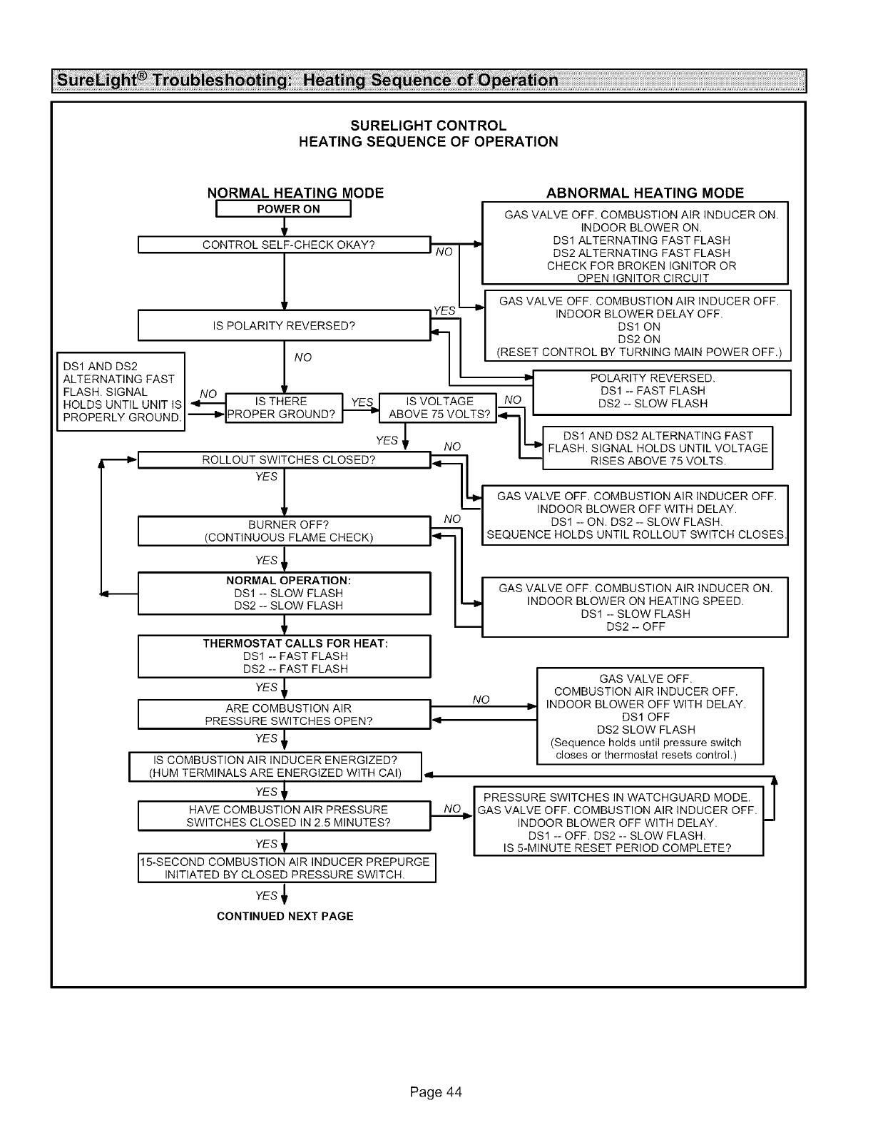
SURELIGHTCONTROL
HEATING SEQUENCE OF OPERATION
NORMAL HEATING MODE ABNORMAL HEATING MODE
IPOWER ON IIGAS VALVE OFF. COMBUSTION AIR INDUCER ON.
IINDOOR BLOWER ON.
CONTROL SELF'-CHECK OKAY'_ I,-- ,_ DS1 ALTERNATING FAST FLASH
I " J NO | DS2 ALTERNATING FAST FLASH
I | CHECK FOR BROKEN IGNITOR OR
,IF -I GAS VALVE OFF. COMBUSTION AIR INDUCER OFF.
vaYES _ INDOOR BLOWER DELAY OFF.
, IS POLARITY REVERSED? I -II OSlo%"
DLSIEA##ADS2 FAST I.[ I' "i POLARITY REVERSED.
FLASH. SIGNAL I NO , • , , I DSI - FAST FLASH
HOLDS UNTIL UNIT ISI_ ISTHERE _ IS VOLTAGE NO DS2 --SLOW FLASH
PROPERLY GROUND.J'--_I PROPERGROUND? _ ABOVE 75 VOLTS? '
-- DS1 AND DS2 ALTERNATING FAST
YES_I NO I q FLASH. SIGNAL HOLDS UNTIL VOLTAGE
ROLLOUT SWITCHES CLOSED? _ I_ I RISES ABOVE 75 VOLTS. I
Y SI II
| I _ GAS VALVE OFF. COMBUSTION AIR INDUCER OFF.
_1 INDOOR BLOWER OFF WITH DELAY.
BURNER OFF'_ I Ni IDSI --ON. DS2-- SLOW FLASH.
(CONTINUOUS FLAME CHECK) I_1- I SEQUENCE HOLDS UNT LROLLOUT SW TCH CLOSES
YES
.qI
I
I
I
NORMAL OPERATION: I
DS1 -- SLOW FLASH
DS2 -- SLOW FLASH
THERMOSTAT CALLS FOR HEAT: I
I
DS1 -- FAST FLASH
DS2 -- FAST FLASH
YES
ARE COMBUSTION AIR I
PRESSURE SWITCHES OPEN? 14
YES
IS COMBUSTION AIR INDUCER ENERGIZED? dl
(HUM TERMINALS ARE ENERGIZED WITH CAI)
YES _
HAVE COMBUSTION AIR PRESSURE
SWITCHES CLOSED IN 2.5 MINUTES?
YES _
_1 GAS VALVE OFF. COMBUSTION AIR INDUCER ON.
INDOOR BLOWER ON HEATING SPEED.
DSl -- SLOW FLASH
DS2 -- OFF
GAS VALVE OFF.
COMBUSTION AIR INDUCER OFF.
INDOOR BLOWER OFF WITH DELAY.
DSl OFF
DS2 SLOW FLASH
(Sequence holds until pressure switch
closes or thermostat resets control.)
$
I PRESSURE SWITCHES IN WATCHGUARD MODE. I I
NI___I GASVALVEOFF.COMBUSTIONAIRINDUCEROFF.V
I - INDOOR BLOWER OFF WITH DELAY.
DSl -- OFF. DS2 -- SLOW FLASH,
S 5-M NUTE RESET PER OD COMPLETE?
15-SECOND COMBUSTION AIR INDUCER PREPURGE I
N T ATED BY CLOSED PRESSURE SW TCH. I
I
YES
CONTINUED NEXT PAGE
Page 44
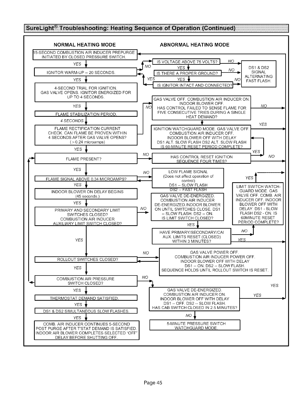
NORMAL HEATING MODE
5-SECOND COMBUSTION AIR INDUCER PREPURGE
INITIATED BY CLOSED PRESSURE SWITCH.
YES _
iIGNITOR WARM-UP -- 20 SECONDS.
YES _
4-SECOND TRIAL FOR IGNITION.
GAS VALVE OPENS. IGNITOR ENERGIZED FOR
UP TO 4 SECONDS.
YES _
IFLAME STABILIZATION PERIOD.
4 SECONDS _
FLAME RECTIFICATION CURRENT
CHECK, CAN FLAME BE PROVEN WITHIN
4 SECONDS AFTER GAS VALVE OPENS?
( > 0.24 microamps)
YES _.
i
I
FLAME PRESENT?
YES _
FLAME SIGNAL ABOVE 0.34 MICROAMPS?
YES _
INDOOR BLOWER ON DELAY BEGINS
(45 seconds.)
YES _
PRIMARY AND SECONDARY LIMIT
SWITCHES CLOSED?
COMBUSTION AIR INDUCER
AUXILIARY LIMIT SWITCH CLOSED?
YES
I
i
i
ROLLOUT SWITCHES CLOSED?
YES _
COMBUSTION AIR PRESSURE
SWITCH CLOSED?
YES _
THERMOSTAT DEMAND SATISFIED.
YES _
DS1 & DS2 SIMULTANEOUS SLOW FLASHES.
YES _
COMB. AIR INDUCER CONTINUES 5-SECOND
POST PURGE AFTER T'STAT DEMAND IS SATISFIED,
INDOOR AIR BLOWER COMPLETES SELECTED "OFF"
DELAY BEFORE SHUTT NG OFF.
ABNORMALHEATING MODE
9,9'NO
&'_P1 IS VOLTAGE ABOVE 75 VOLTS.
NO YES ,,- I DS1 & DS2s, .AL
• - ' I ALTERNATING
|YES YES tNOI FAST FLASH.
IS IGNITOR INTACT AND CONNECTED?_'[ ___
GAS VALVE OFF. COMBUSTION AIR INDUCER ON.
I _,] INDOORBLOWEROFF. I
I I NO
INo,HASCONTROLFALEDTOSENSEFLAMEFOR
'1 '1 FIVE CONSECUTIVE TRIES DURING A SINGLE
' I I HEATDEMAND? I
/ t YES
i i I,GN,T,ONWATCHGUARDMODEGASVALVEOFFi
t_ I COMBUSTION AIR INDUCER OFF. /
I I INDOOR BLOWER OFF WITH DELAY
DSl ALT. SLOW FLASH DS2 ALT. SLOW FLASH
I I IS 60-MINUTE RESET PERIOD COMPLETE? I I
YES I
HAS CONTROL RESET IGNITION _l_' NO
I I SEQUENCEFOURTIMES? /
i
I
I
LOW FLAME SIGNAL I
I
(Does not affect operation of
control)
DSl -- SLOW FLASH
DS2 -- }-ASI FLASH
GAS VALVE DE-ENERGIZED.
COMBUSTION AIR INDUCER
DE-ENERGIZED.INDOOR BLOWER
ON UNTIL SWITCHES CLOSE. DS1
-- SLOW FLASH. DS2 -- ON.
IS LIMIT SWITCH CLOSED?
YES _
HAVE PRI MARY/S ECO N DARY/CAI
AUX. LIMITS RESET (CLOSED)
WITHIN 3 MINUTES?
YES l
LIMIT SWITCH WATCH-
GUARD MODE. GAS
VALVE OFF. COMB. AIR
INDUCER OFF. INDOOR
BLOWER OFF WITH
DELAY. DSl - SLOW
FLASH DS2 - ON. IS
60MINUTE RESET
PERIOD COMPLETE?
NO _f
YES p
NO GAS VALVE POWER OFF.
COMBUSTION AIR INDUCER POWER OFF.
INDOOR BLOWER OFF WITH DELAY
DSl -- ON. DS2 -- SLOW FLASH.
SEQUENCE HOLDS UNTIL ROLLOUT SWITCH IS RESET.
I_-_ GAS VALVE DE-ENERGIZED. I
COMBUST ON A R NDUCER ON I
I INDOOR BLOWER OFF WITH DELAY I
DS1 -- OFF. DS2 -- SLOW FLASH.
I HAS CAB SW TCH CLOSED N 2.5 M NUTES?
NO_
WATCHGUARD MODE.
YES
YES Iii
Page 45

SURELIGHT CONTROL
COOLING SEQUENCE OF OPERATION
NORMAL COOLING MODE ABNORMAL COOLING MODE
POWER ON. I
IiGNITION CONTROL MAIN POWER ON. I
I CONTROL SELF DIAGNOSTIC CHECK.
IS CONTROL OPERATING NORMALLY?
GAS VALVE OFF. COMBUSTION AIR INDUCER
OFF.
INDOOR BLOWER OFF WITH NORMAL DELAY.
SIGNAL CIRCUIT BOARD FAILURE AT DSl & DS2.
.......................................
I1"_ I ERRUr I IVl_ll_ rUVVER I U REOE I bUl'_ I RUL,
I IS POLARITY REVERSED? _ DSl FAST FLASH DS2 SLOW FLASH. I
DS1 AND DS2 NO 1
ALTERNATING FAST I NO , • , , DS1 AND DS2 ALTERNATING FAST
FLASH. SIGNAL _ IS THERE _ IS VOLTAGE _ FLASH. SIGNAL HOLDS UNTIL VOLTAGE
I HOLDS UNTIL UNIT IS I_1 PROPER GROUND? I_IABOVE 75 VOLTS? RISES ABOVE 75 VOLTS,
LPROPERLYGROUND.j
NO GAS VALVE OFF COMBUSTION AIR INDUCER OFF
RO LLO UATR_V_TC LHESTMyESO_'TOHREsDCL_)NTEINUO U_ LY '1--_ S ES I_ECR_R_LL_DW EuBROi,iFRV_oIAiHu:RO_MwTA_:&:AY_ _ S.
I CHECK FOR MAIN BURNER FLAME SENSE.IS MAIN BURNER FLAME OFF?
I OSl OS :S OW AS AT A,.S1
UNCHANGED THROUGHOUT COOLING CYCLE.
I THERMOSTATCALLSFORCOOLING.1
COMPRESSOR CONTACTOR AND SYSTEM FAN
ENERGIZED WITH 2-SECOND DELAY. COOL
SPEED TERMINAL IS ENERGIZED. EAC
TERMINAL IS ENERGIZED,
THERMOSTAT OPENS. J
COMPRESSOR OFF. 1
SYSTEM FAN AND EAC TERM. OFF 1
WITH2-OR45-SECOND DELAY, 1
GAS VALVE OFF. COMBUSTION AIR INDUCER OFF.
INDOOR BLOWER OFF WITH NORMAL DELAY,
SIGNAL CIRCUIT BOARD FAILURE AT DSl & DS2.
SEQUENCE HOLDS UNTIL FLAME IS NOT SENSED,
I
I
I
Page 46
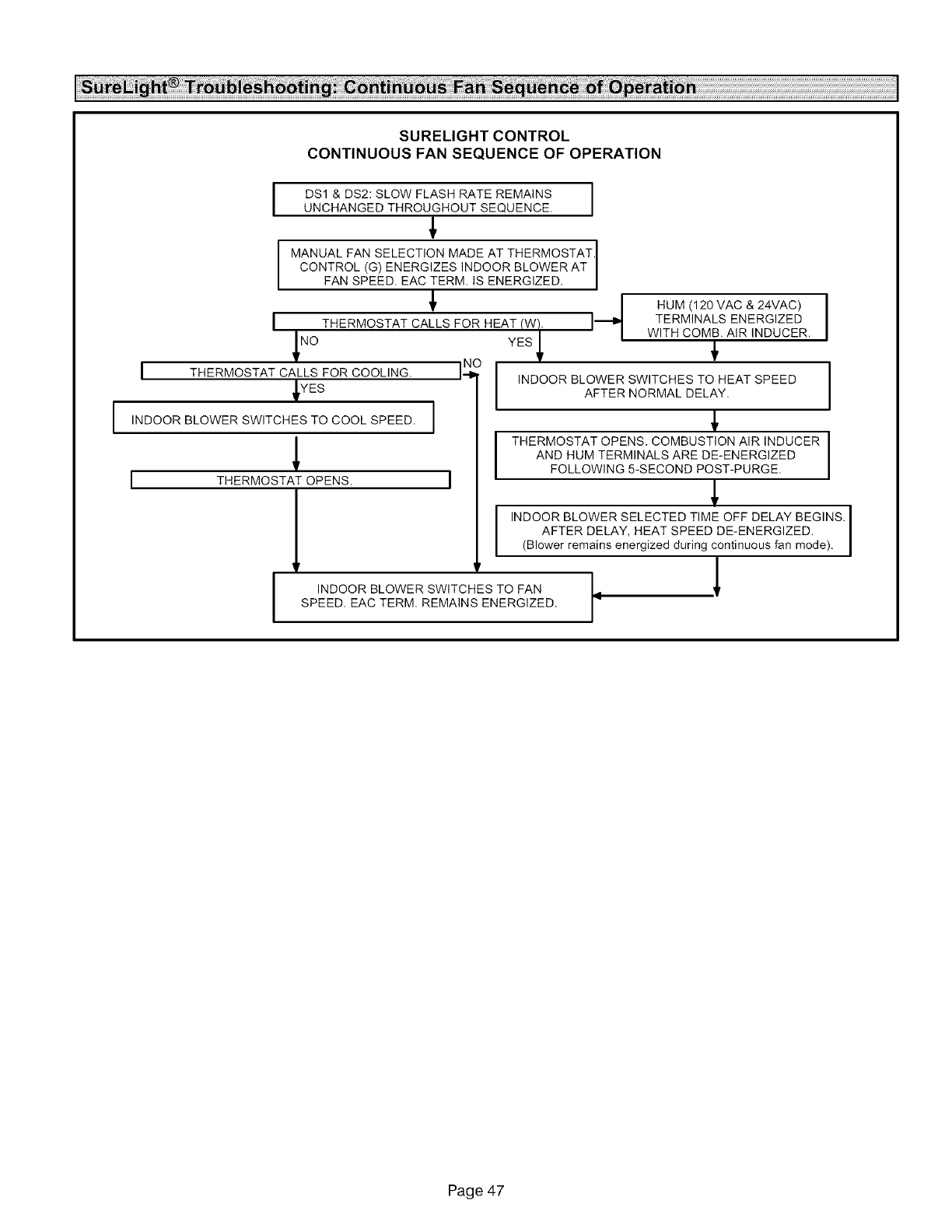
I
SURELIGHT CONTROL
CONTINUOUS FAN SEQUENCE OF OPERATION
I
I
I
DS1 & DS2: SLOW FLASH RATE REMAINS I
I
UNCHANGED THROUGHOUT SEQUENCE.
+
MANUAL FAN SELECTION MADE AT THERMOSTAT.
CONTROL (G) ENERGIZES INDOOR BLOWER AT
FAN SPEED. EAC TERM. IS ENERGIZED.
' -4
THERMOSTAT CALLS FOR HEAT (W). I
NO
THERMOSTAT CALLS FOR COOLING.
YES
INDOOR BLOWER SWITCHES TO COOL SPEED.
THERMOSTAT OPENS.
J
INDOOR BLOWER SWITCHES TO FAN
SPEED. EAC TERM. REMAINS ENERGIZED.
HUM (120 MAC & 24MAC)
TERMINALS ENERGIZED
WITH COMB. AIR INDUCER.YES +
INDOOR BLOWER SWITCHES TO HEAT SPEED
AFTER NORMAL DELAY.
+
I THERMOSTAT OPENS. COMBUSTION AIR INDUCER I
AND HUM TERMINALS ARE DE-ENERGIZED
FOLLOWING 5-SECOND POST-PURGE.
m
INDOOR BLOWER SELECTED TIME OFF DELAY BEGINS. I
m
AFTER DELAY, HEAT SPEED DE-ENERGIZED.
(Bower rema ns energ zed dur ng cont nuous fan mode).
.1
Page 47

Step 1
Step 2
Step 3
Step 4
Step 5
Step 6
Proposed vent pipe size :
Termination kit catalog number :
Vent pipe equivalency value from table 5 :
Total number of 90 ° elbows required (indoors and outdoors)
X 5 = equivalent feet of pipe
Total number of 45 ° elbows required (indoors and outdoors)
X 2.5 = equivalent feet of pipe
Linear feet of straight pipe required :
Add equivalent feet of vent pipe listed in
steps 2 through 5.
Equivalent Feet
TOTAL
If the total is equal to, or less than, the allowable maximum given in table 7, the proposed pipe size is acceptable. If the
total exceeds the maximum allowed vent pipe length, repeat the process above using the next larger diameter pipe until
an acceptable total is achieved.
NOTE -In Direct Vent systems, total the equivalent length of either the exhaust OR intake piping run, depending upon which
will be LONGER. Intake and exhaust pipe diameter must be the same size and must be terminated in the same pressure
zone. Intake and exhaust pipe should be roughly the same length.
Job Name Job No, Date
Job Location City State
Installer City State
Unit Model No, Technician
Serial No,
Heating Section
Electrical Connections Tight?
Supply Voltage
Blower Motor Amps []
Fuel Type: Natural Gas? []
Furnace Btu Input
Line Pressure
[] Blower Motor H.P.
Gas Piping Connections
Tight & Leak-Tested?
LP/Propane Gas? []
Regulator Pressure __ w,c, - Nat,:
Flue Connections Tight? []
Condensate Connections Tight? []
Combustion Gas Tested? [] CO2 [] CO
Fan Control Setting
(45 Seconds Fixed On)
Fan Control Off Setting
Filter Clean & Secure? []
Thermostat
Calibrated? []
w,c, - LP/Propane
Proper Draft? []
Temperature Rise
Vent Clear? []
Heat Anticipator Properly Set? []
D
Level? []
Page 48
