LENNOX Furnace/Heater, Gas Manual L0806194
User Manual: LENNOX LENNOX Furnace/Heater, Gas Manual LENNOX Furnace/Heater, Gas Owner's Manual, LENNOX Furnace/Heater, Gas installation guides
Open the PDF directly: View PDF ![]() .
.
Page Count: 19
LENNOX
Industrio$ Inc.
INSTALLATIONINSTRUCTIONS
500,430M
Supersedes 500,273M
ACCESSORIES
0 • • ••• ••••••••••
INSTALLATION INsTRucTIONS FOR KL-4.5 RELAy CONTROL CENTER
I_:_SHIPPING AND PACKING LIST:
l-RL-45 relay con_ol center
1-Thermostat (if ordered)
l-The_mostat sub-base (if ordercd)
l-Magnetic starter (i._ ordered)
1-20-S Solenoid (if ordered)
Ior 2-Wire kits (if ordered)
1to 3-Au.xillary" limits with mozm_tng brackets (if ordered)
1-Wiring diagram
H-GENERAL:
This relay con_ol center can be used to interlock up to
three heating units with three blowers. System can be piped
and wired to operate in _ one of the following ways:
A-SINGLE STAGE HEATING - SINGLE STAGE COOLING
B-TWO-STAGE HF__TING - SINGLE STAGE COOLING
C-SI_4GLE STAGE HEATING - TWO-STAGE COOLING
D-TWO-STAGE HEATING - TWO-STAGE COOLING
E-S]_4GLE STAGE HEATING -TWO-STAGE COOLING WITH
CYLINDER UNLOADING
F-TWO-STAGE HEATDqG- TWO-STAGE COOLING WITH
CYLINDER UNLOADING
Be sure the correct items have been ordered_ from fl_e BiLls
of Material in the ISL'lce book_ for the system operation you
require.
The blower motor contector in the relay control center is
rated for one 1 hp or two 1/2 hp motors at 120 volts end one
2 hp or three 3/4 hp motors at 230 volts) single phase. If
3phase or larger motors are used) a magnetic starter must
be used.
III-OPERATION__ :
The heat relay is energized from the thermostat and will
energize all three ftamaces simultaneously. If _Z_aaces are
wired for two-stage operation) asecond stage heat relay kit
mu_ be installed and wired in tile relay centrol center.
The time delay blower relay is energized on first stage heat
demand and will start all blower motors _tmultaneously in
approximately 30 seconds. After end of heat dem;md)
blowers will operate for approximately 90 seconds _nd fl_en
shut off. If thermostat blower _vitc_ is placed in the "Cont."
The condensing units are energized directly from the ther-
mostat on acooling dem_d. On two-stage cooling) ugtng
two condensing unitm, the first and second Stage cooling
bulbs will operate conder_h_ units on demand. _ single
condensing unit is v_ed with an eVaporator solenoid for two-
stage cooling (cylinder tmloading)_a second stage cooling
relay must be installed and wired in the relay contcol center.
On COOl.ing demand_ with blower switch On thermostat in
"int. " positio% the blowers will be automatically energized
on first Stage call for cooling. If thermostat blower fwiW.Ya
is placed in the "Cont. " position) blowe_ will operate con-
_no_l_.
This equipment shall be installed and wired according to
local codes. Authorities having jurisdiction should be con-
gvlted before instrUction.
V-_[NSTALL GAS PIPING..
Figure 1shows asuggested method of piping these units,
This figure applies to Landmark traits only. Use same pr_-
ciple for other Lennox tmlts, howeVer, some variatior_ in
fittings may be nece_a_y.
Size pipLng in accordance wt_ local codes.
Page 1
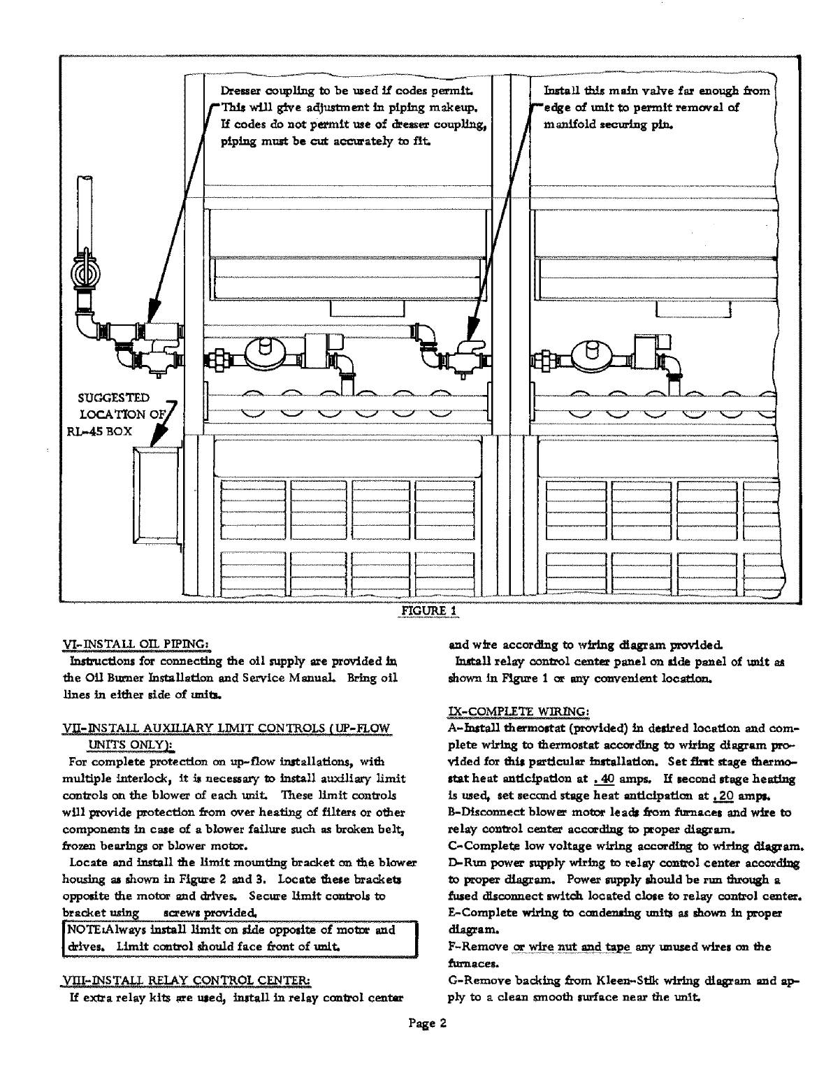
Drene_ coupling to be used ff codes permit.
-This will give adjustment in piping makeup.
Ifcodes do not permit me of d_essercoupling,
piping m_t be cut acc_atdy to tiC.
FIGURE
/
VI-INSTALL OIL PIPING
Instructionsfor connecting the oil supply are provided In
the Oil Btumer Installation and Service Manual Bring oil
lines in either side of unitL
V_-INSTALL AUXILIARY LIMIT CONTR_
For complete protection on up-flow installations, with
multiple Luterlock, it i_ necessary 0o i1_*tall auxiliary limit
controls oa the blower of each 11nlt. T_ese limit controls
will provide protection from over hea_ag of filters or o_her
compone_ats in case of a blower failure such as brokers bel_
frozen bearings or blower mot_.
Locate and i_t_all the limit mounting bracket on the blower
housing as shown in Figure 2and 3. Locate these bracketl
Opp_t@ the mot_ and drives, Secure IL-nit conta'ols to
screws provide&
install limit on side opposite of mot0r and ]
!d#ives. Limit control should face front Of unit. J
If e_a relay kits _e ule_ install in relay control center
and wire according to wiring diagram provide&
Installrelay control center panel on aide panel of unit
shown in Figure 1 or any co_'eulent location.
_COMPLETE WIRING;
A-/a_tall thermostat (provided) in desired location and com-
phte wiring to thermostat accor_ag to wiring diagram pro-
vlded for this particular in_allatica_. Set tint stage thermo-
Stat heat anticipation at .40 amps. If second stage heating
is medt act sec_d stage heat entldpation at. 20 amp_
B-Disconnect blower motor hack from furnaces and wire to
relay control center according to l_oper diagram.
C-Complete low voltage wiring according to wiring diagram.
D-Run power supply wiring to relay control center according
_0 proper diagram. Power supply should be run lhrough a
fused disconnect switch located clo_e to relay control center.
F-Complete wiring to condensing uni_ as shown in p_per
_am.
F-RemoVe ,_qr_e nut a.udt'ape any unused w_es on the
_urnaces.
G-Remove backing from Khen-Stik wiring diagram and ap-
ply to adean smooth |udace near the unR:,
Page 2
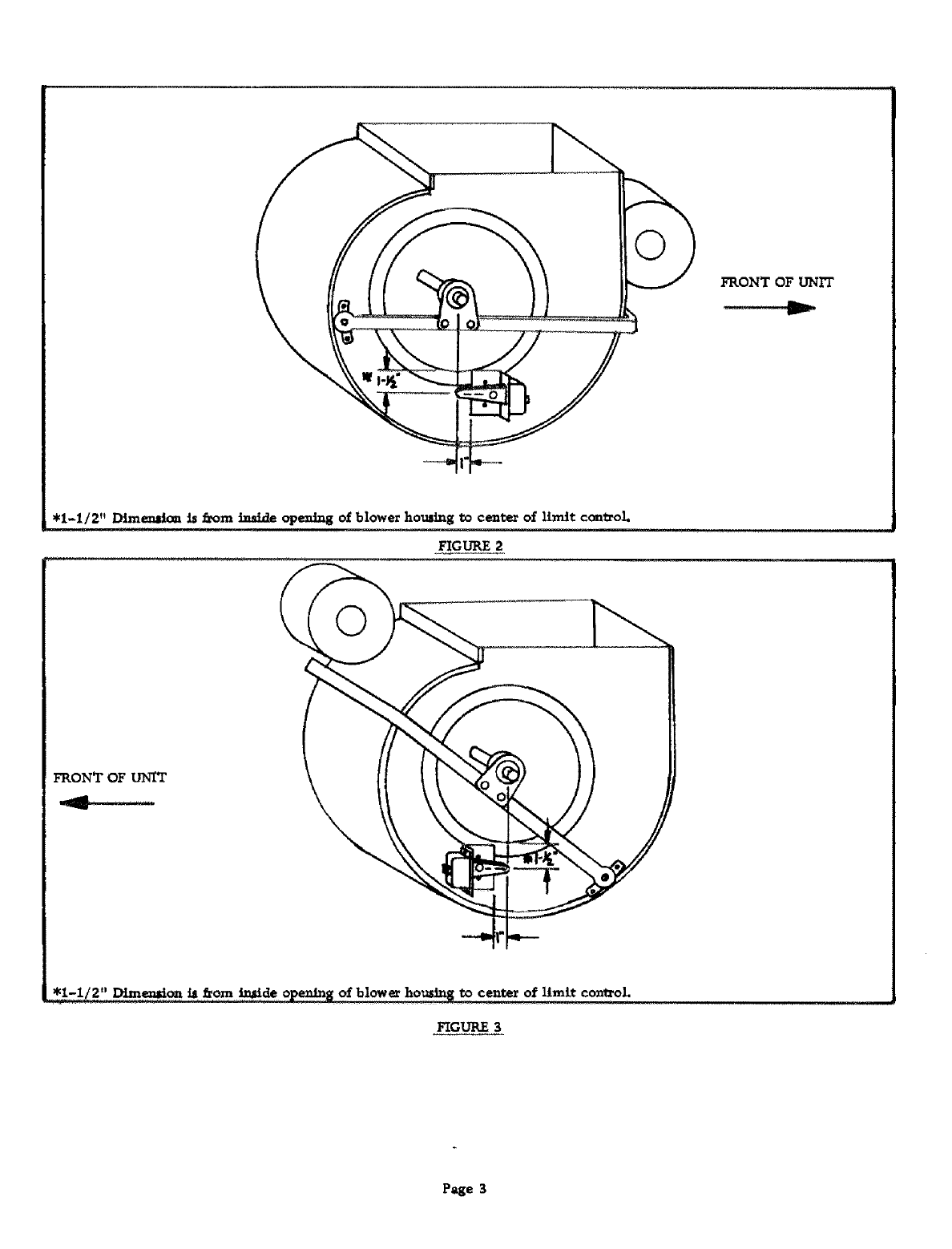
FRONT OF UNIT
• 1-1/2" Dimension is fxom inside opening o_ blower houcl_g to center of limit c_trol.
FIGURE 2
FRONT OF UNIT
_enM0_ _ from _.___o]_ o_blow_.hOu _ to center of limit con_ol.
FIGURE 3
Page 3
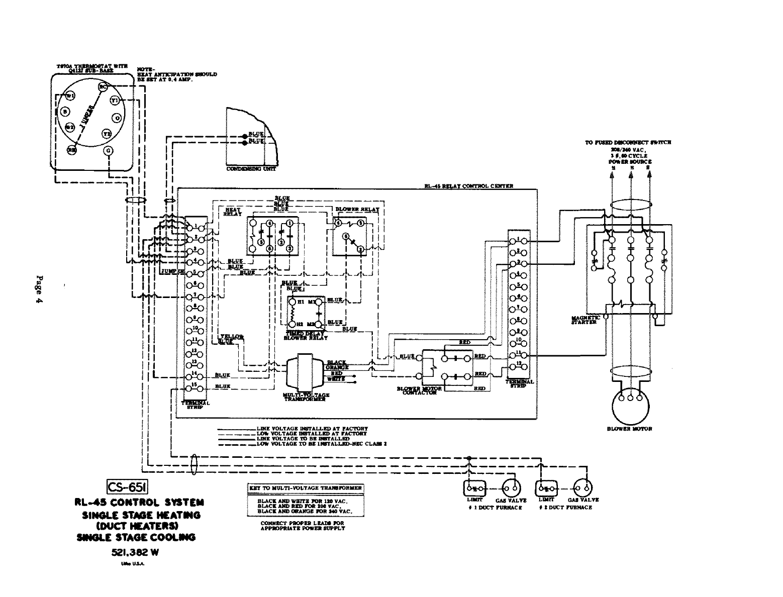
RL-45 CONTROL SYSTEM
SINGL[ STJI_E H[ATING
(DUCT H£AI_RW
SINGLE STAGE COOLING
521.382 W
Uam U_S_
I_-4_ _J_L_T CGM'TMOLCEWTE_
- - ------_--_--_---- 7
4J 1_T FURN&CE _ | DU_T gO,MACE
BI,O_n I_TOII

T_AT
W_rTE.
JLF.AT _ATION _U'._D
' BE SKT AT O, 4 AMP.
I
I
I
I
I
I
I
L
1cs-6521
RL-4S
CONTROL SYSTEM
SINGLE STAG[ HEATING
SINGLE STAGE COOLING
521,383 W
VOLTAGE IN_TALLH_ AT FACTO_f
LO_ VOLTAGE _'TALLE_ AT FACTORY
L_E VOLTAGE TO BI_ DUTALLKD
-- -- --_ LO_k _LTAGE TO BE _q_t'ALLI_N_ C_JdIB
I
I
I
f
I
I
I
I
I
I
I
II
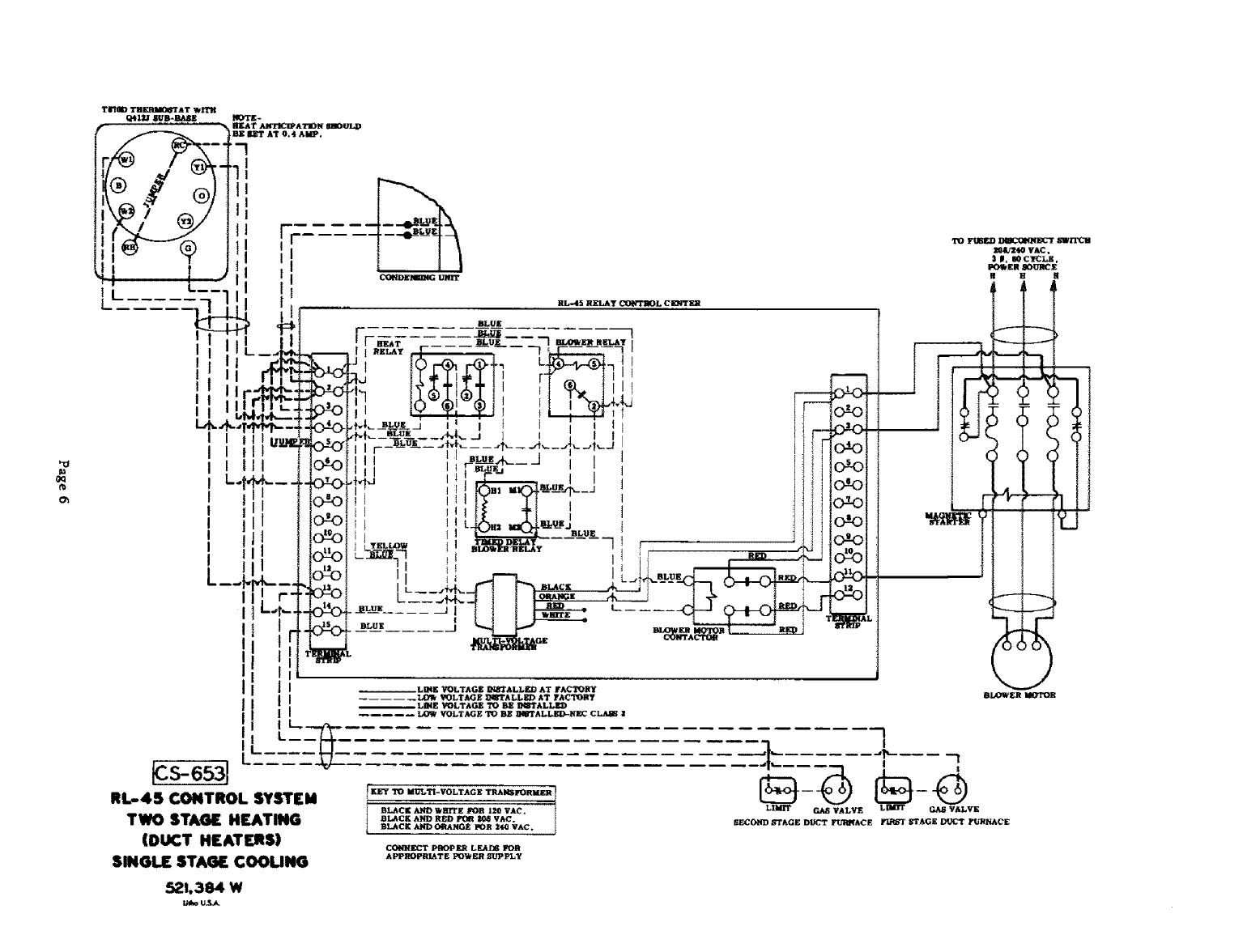
_S-653J
RL-4S CONTROL SYSTEM
TWO STAGE HEATING
(DUCT HEATERS)
SINGLE STAGE COOLING
BLOWER RELAT
I
BLUE I
()
521.384 W
OQ
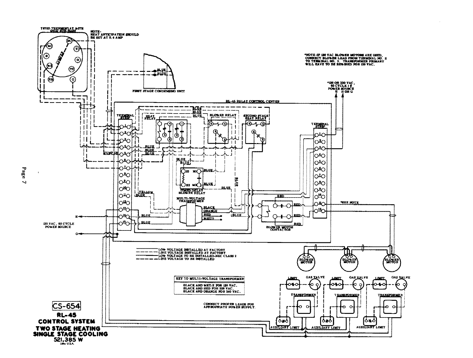
RL*4S
CONTROL SYSTEM
TWO STAGE HEATING i
SINGLE STAG[ COOLING
57.1.385 W
Lk_ U_
RL-4$ BAL*AY C_ CEIqTElli
q_'rK-IF LlO VAC Ba,OWl_ _ ARE IJ_D.
BLO_Fd¢ LgAD FROM TgRId_AL NO, U
TO TF.I_]_AL NO, 3. TII_MER PRlhlAHy
WiLL HAVl_ _Bl_ REIklED POR 120 VAC°
Ol20 OR _0 VAC,
60 _CLE Ig
I:_W _R lOUISE
HOBG
_EE NOTE
--'LO_ VOLTAGE ]_[_JI_ALLED AT FACTOH¥
...... L_E VOLTAGE _ALLED AT FACTC_Y
VOLTAGE TO BE INSTALLF.D.NE_ CLAS_ 2
LINE VOLTAGE TO BE INSTALLED
r
I,_ _o uu_1 K-_LT_: Te_'SFOe_ZR I
iBL_¢K _'D _un z_ _o vAC
BLACK _HED FOR _VAC.
[BLACK AND O_ANGE _OR 14G VAC. i
C_ PIM_PER LEADS FOR
APP_PRIATE PO_ _R BUPPLY, I I- ' |4J
gq
oo
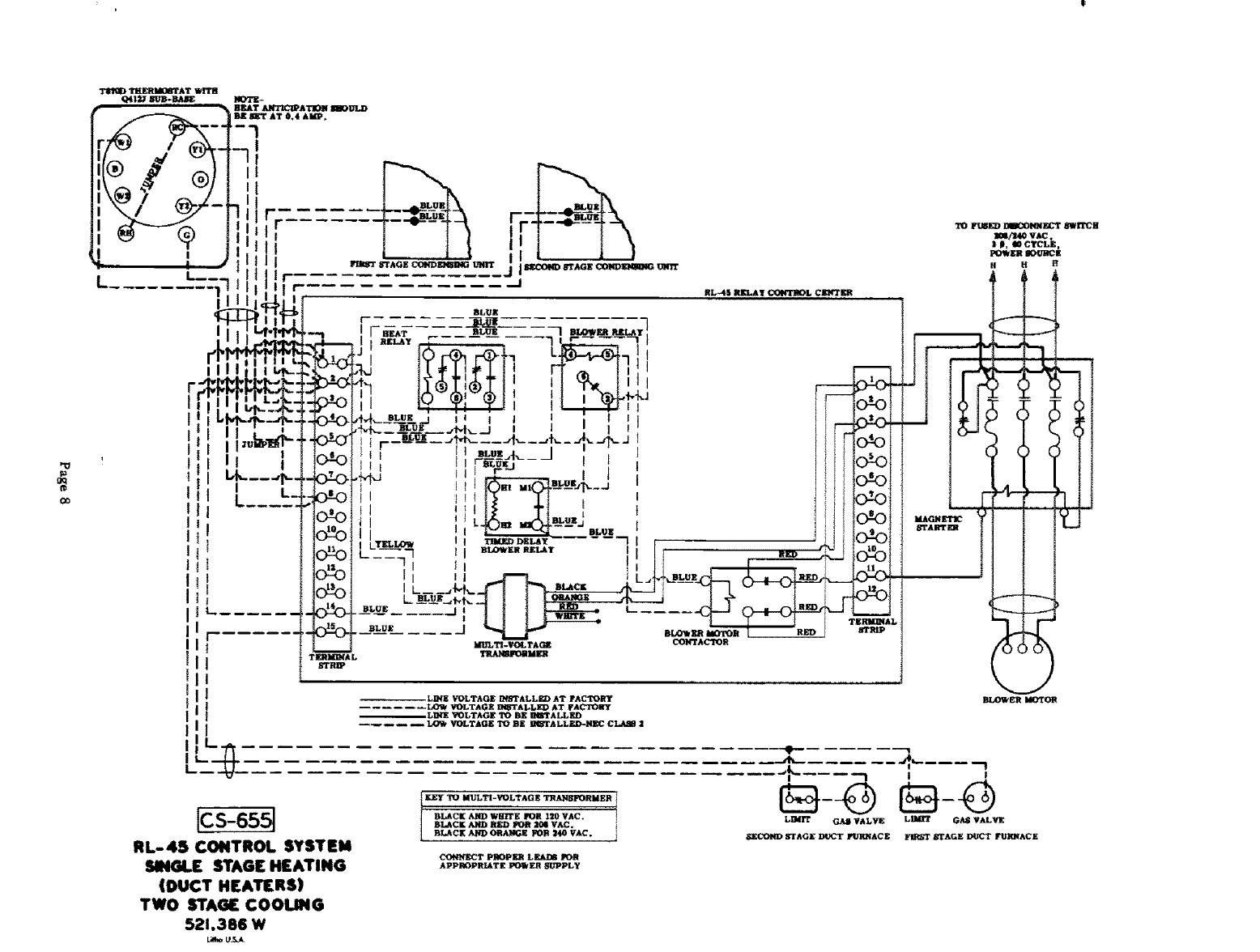
Ics' ssl
ILL-45 CONTROL SYSTEM
SINGLE STAGE HEATING
(DUCT HEATERS)
TWO STAGE COOLING
521,386 W
C_IqN]K_T Pl_OPli_ LEA/_ I_OB
APPROPRJATE I_WEI_ _Ig'PLy
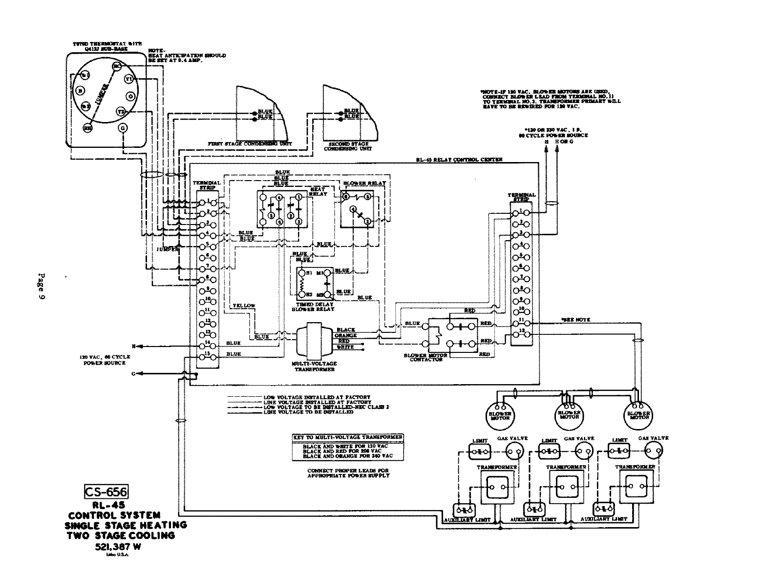
"O
RL-4S 1
CONTROL SY $TIrM
SINGLE STAGE HEATING
TWO STAG[ COOLING
521.387 W
_ko U.S.A
_,_._ _m.,=._. _ _,
TIB_QI_qJ. m).3. TRAIMM_ ma_ FIUIAIty WILL
M_I+fE 'FD IW_ I_I[WlWUED IPWMI IllO VAC.
0
III
r
t
!
!
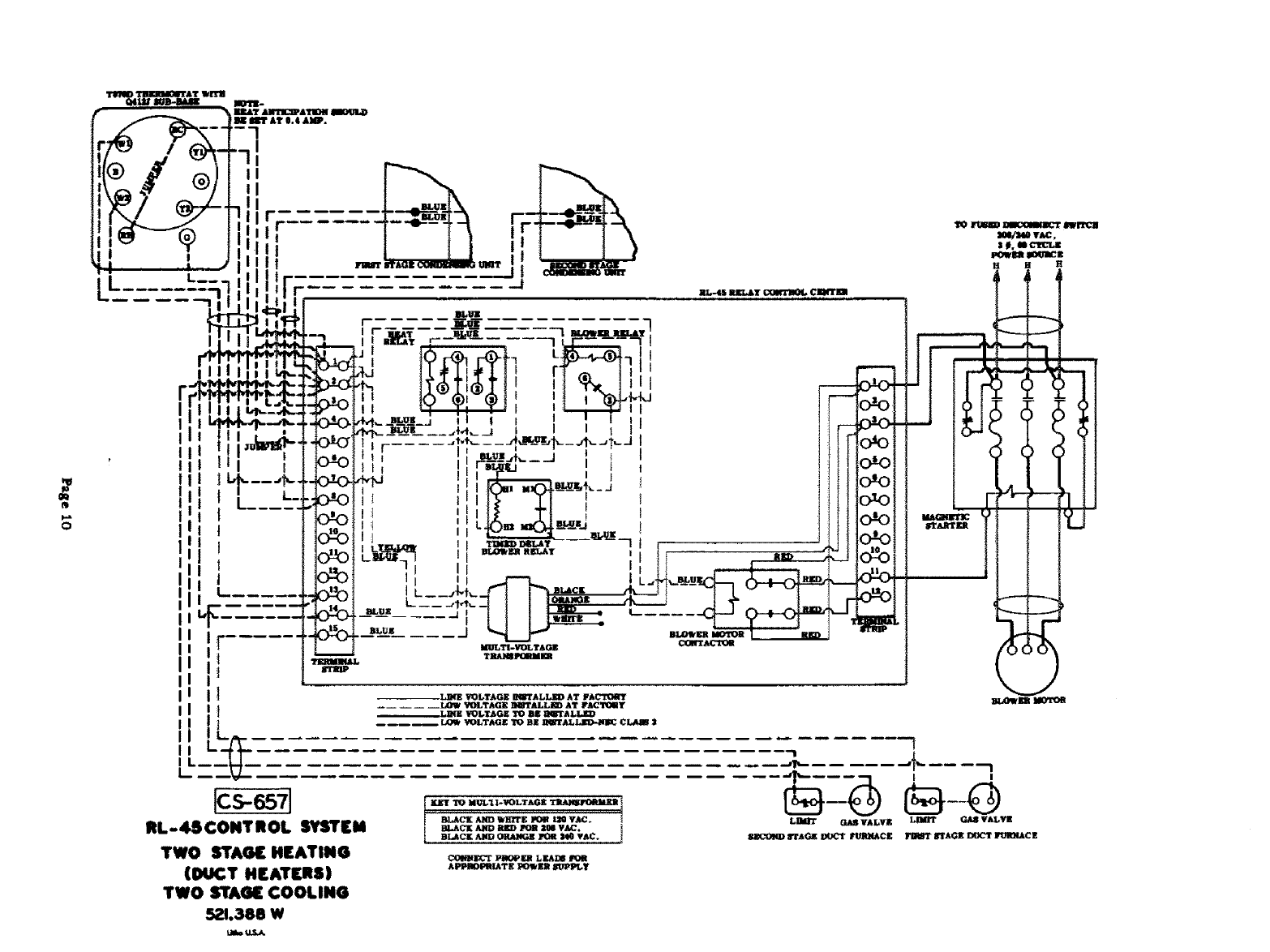
TWO STAGE HEATING
(DUCT HEATERS)
TWO STAGE COOLING
521.386 W
k@k=U.S_
b.L
I
I
I
I
I
|
I
I
!
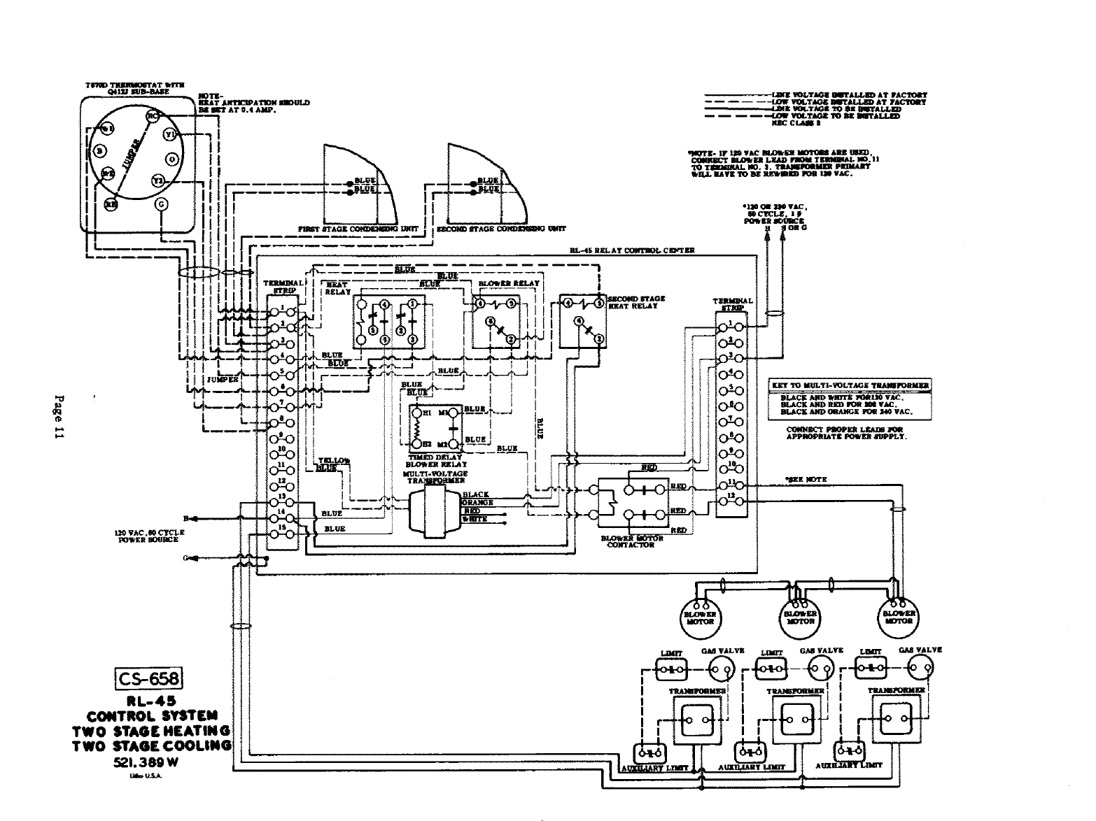
Rl.-45
CONTROl. SYSTEM
TWO STAGE HEATING
TWO STAGE COOI.ING
521.389 W
!
I.._m.,,_I I_,,i_, ! _._,,.o_.n
iIL _,
m:t
oq
I
I
I
I
I
I
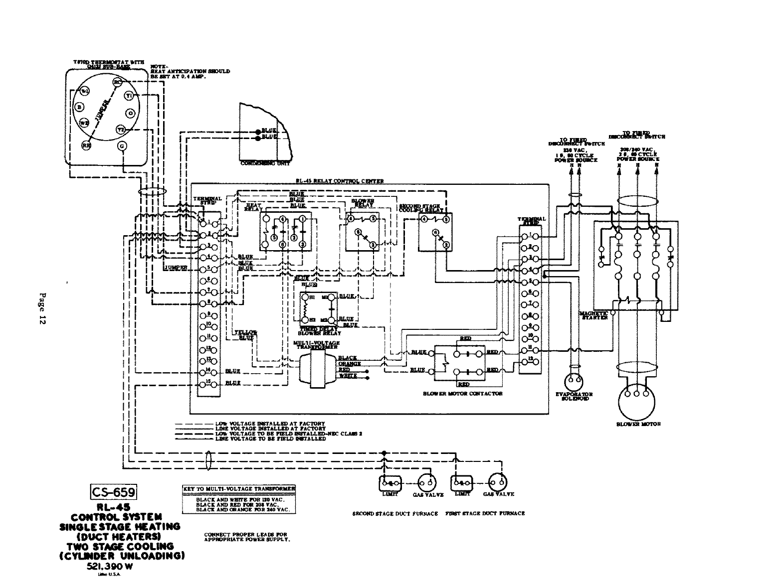
[CS-659]
RL-4S
CONTROl. SYSTEM '
SINGLE STAGE HEATING
(DUCT HEATERS)
TWO STAGE COOLING
(CYLINDER UNLOADING)
521,390 W
i
]
J
j-
io_o
olo
!o_o
oeo
i
_K_ "tO MULTI-VOLTAGE _PGRMEI_
BLACE AND WZlI_IFI_ I_1t 120 VAC.
•.,k.
81_0111) STAGI_"DIX_'I"FI_NAC_ __T#,G_ DOC3" FOIIN_C_
CO(_NE_T PROPER LI_I_ I_FI
ApPrOPRIATE POWER SUPPLy.
H N
i
sl WCTC'L.k
!II
----h
I
i
()
r_
tp
I
,,lllYr It-IF _ VAC III,O_ ml MO'l_ms A.EE W41:D.
CONN]IiI_T B[._ EB LEAD _T DIMBL4.L NO.II
TO TIDIIIIII_L NO.I. _1_1 PIIlMAIIT
IIFILL HAVE TO BE IEl_ mid PDll 130 VAC.
"LIB OR _VAC
l0 CYCLE ig
P011_ Eli IIOtJB_ K
,,.J
•_ VO_TA:G_ II_FFALL*_ AT YA_TOHY
LINE VOt.TA_ h_JTALLE_) AT FAC_Y
LOW VOLTAGF_ TO BJ_ I$_TAL_KU_NJ_ CLKS$ I
_.LINE VOLTAGE TO BE _ALLKD
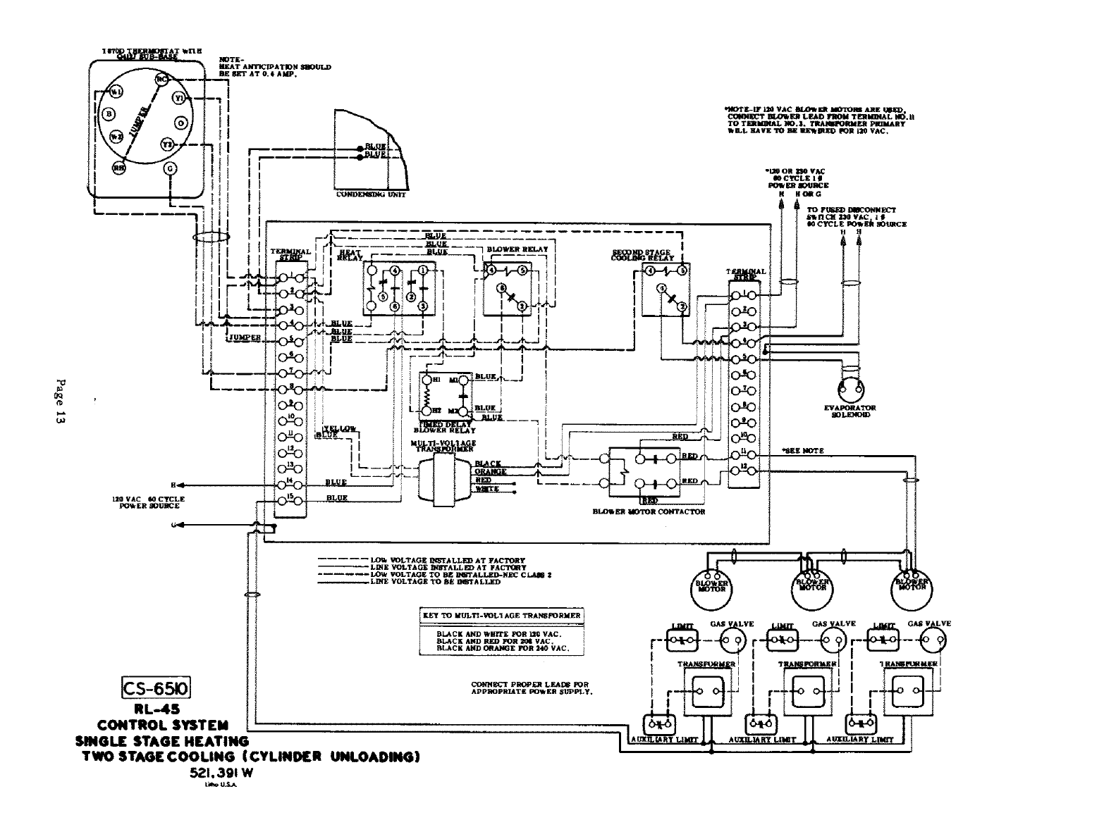
RL-4S
CONTROL SYSTEM
SINGLE STAGE HEATING
TWO STAGE COOLING (CYLINDER UNLOADING)
521.391W
TO MULTt-V_L1 AGE TRAH_?OBMI_II ]
BI_CK AND WIlliE _ 110 VAC. i
BI_CK AND lIED I_INI I1_ VAC. i
_OBNI_'T PEOPI_ L&.AD$ P0R
APPI_PRIATE I:_WER _PPLY.
t
H HO_G
tl
G_S VLVE GAS LVE GA*q V LVE
l t_--I!1 ! l_ll I tf III
tr-++o o-!+_ _ r-+_o oH_ ! rff_ °t-_
I1"_""'_"";1' *'_"''" 't ""_"'_"" ' t
j_
QQ
t..6
,p,
I I
zl !
L
I
I
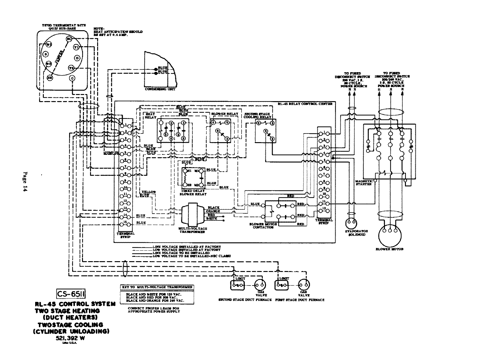
ICS-65111
RL-4$ CONTROL SYSTEM
TWO STAGE HEATING
(DUCT HEATERS)
TWOSTAGE CO0!.IN6
(CYLIND[II UNLOADING)
$21,392 W
Lk_c, ULS.A.
COI(IqECT PIgOPl_q LF, A/_ POR
APPIIOPI_IATE POWER gUPP'LY
VALVZ VALV][
II01_-"OND 6"TAG_ DUCT FQII_IACE _ STAGZ _ FU'/tNA_I_
F
I
1
I
I
O01_ql_'t I/.Olk I_ LIIAI) FIDII TIIIIIa_AL II0. I i
_IIaMINAL I0.I , 'l'llAlllll_lllllalll
Ibl:l_L ILIVII TO _ ]Ill.flUID _ Im V&C.
HI, W C,n::LII
PO_ i:11 IIOIJIK_E
II B CNil G 1'0_
#ZN I_AC ,1 _1,
PO_ml IK)U]ICll
EVAPOP.ATO_
]
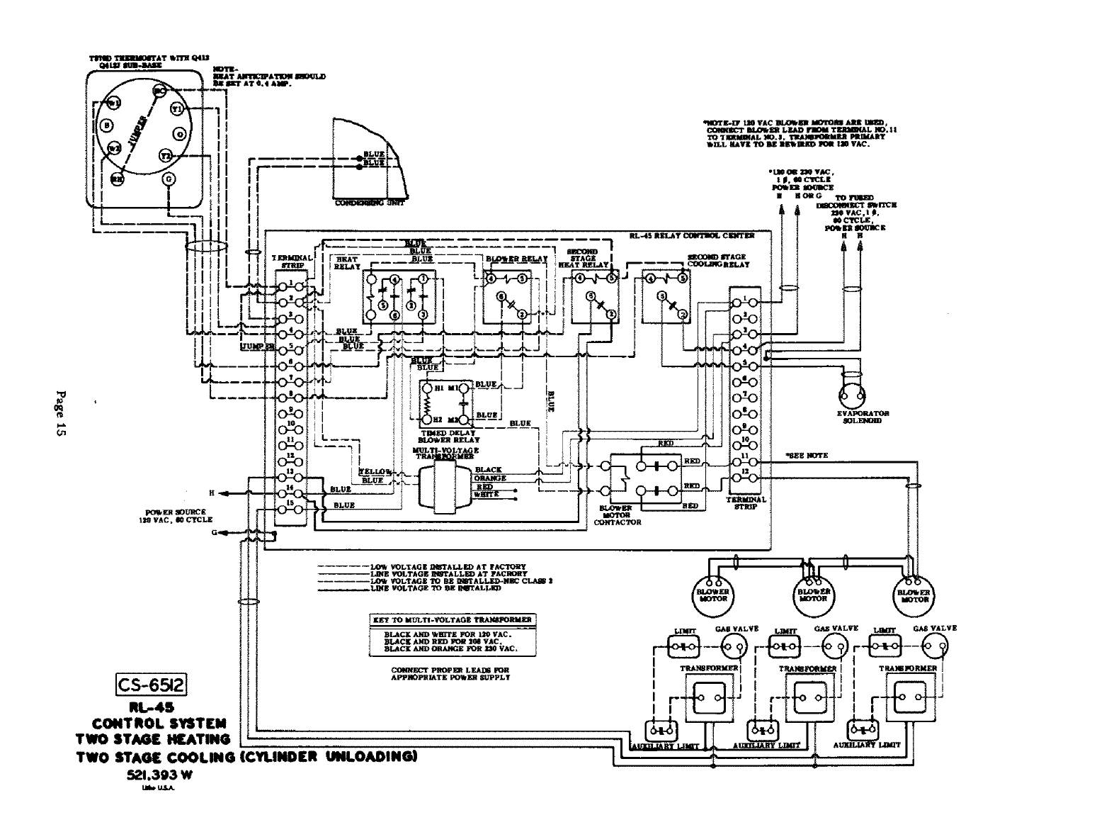
CONTROL SYSTEM
TWO STAGE HEATING
TWO STAGE COOLING (¢Yi.lliOEit UtiLOADIN_)
$21.393 w
Ulw U3_
T]I][IrmI[NITAT
I
t
1
t
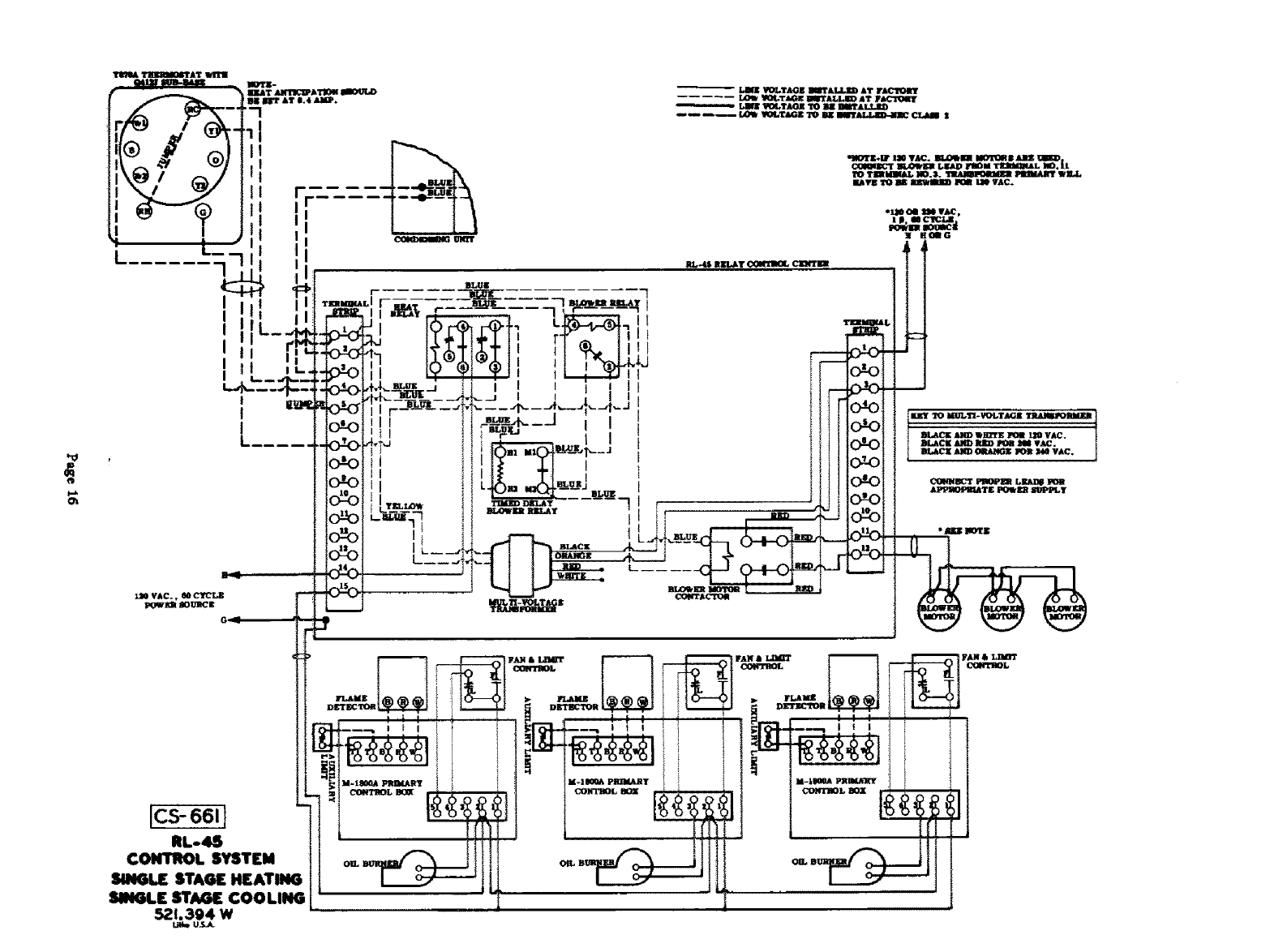
[cs-661]
RL-4S
CONTROL SYSTEM
SINGU[ STAGE HEATING
SN4GLE STAGE COOLING
521.394 W
r
I
I
I
I
rL4ME
D£'I'KCTO_
_,'_%-'T/!I'---I_ °_"
VGLTAGI JlIT&LL]m AT FACI_OItY
2 KT,IGE III_'ALI/D IT FICP0IT
L,arlt I_4*TJ_It TO Bit 8II_AL.YJ;D
W)LTAGZ TO mr lllfr_ €1,'dll_ I
RL,'4_ ll]tll_T _ CllgltTil_
TOTIRI_JU.L NO.3. _PlFIMART WKJ.,
Jb_1511_0 IlK miltlt:D POIt I.N V&C.
"_.I_GQG
B[,ACI[J_ NJ_I)POB _4 VA£_. I
BL4C[ AND _ _ _40 VAC.
&PPRGPI_ATE PO_I_ SI_q_PLy
FAN& LIItm_
I I I I
_--'-t I I I • '
f

L
"u
o_
]CS-662]
RL-4S
CONTROL SYSTEM
TWO STAG[ HEATING
TWO STAGE COOLING
5.?.1.395 W
L_m U_
BLUE
i _ FLAME
DETECTOR
"-_ ! ! ! i ' i
]
F&B & L_nT
CONTROL
O_
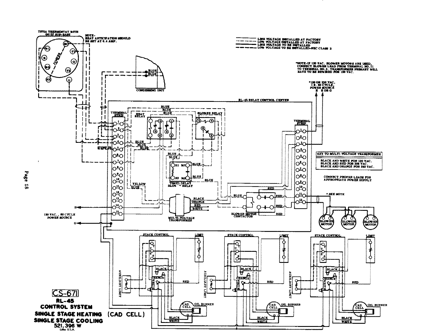
RL-4S
CONTROL SYSTEM
SINGLE STAGE HEATING
SINGLE STAG[ COOLING
521,396 W
CELL) ,1
f_
_D
1
1
I
I
I
I
i
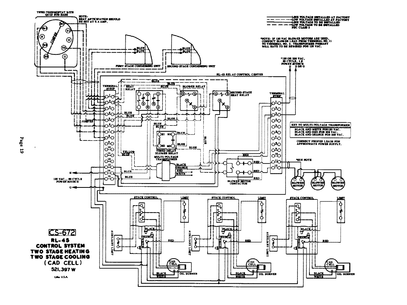
RL-4$
CONTROL SYSTEM
TWO STAGE HEATIN G
TWO STAGE COOLING
( CAD CELL)
521,397 W
Uee u.5_q.
RL-4$ RI_A¥ C_t"/_OL Cl_ITER
II
I
C_NTAC'J_E
÷
I
•l,JIt_ I_TAGK I]IITAI_ED AT FA_OI_JI'
VOLY_Z O[Q_ AT lrA_
LmZ 1FO_TJ_GK1_Oll_ IIBI*_
Iq_ cT_uB |
T_MBIAL NO, s. Pll_fA_y
WIi_L _Vg TO BK RI_B_ _L_ VAC,
*_ OR I_ VAC,
t
APPMOPRI_TE POWER _JPP1LT.
