LENNOX Furnace/Heater, Gas Manual L0806204
User Manual: LENNOX LENNOX Furnace/Heater, Gas Manual LENNOX Furnace/Heater, Gas Owner's Manual, LENNOX Furnace/Heater, Gas installation guides
Open the PDF directly: View PDF ![]() .
.
Page Count: 56
LF WVOX)
®
_ 2006 Lennox Industries Inc.
Dallas, Texas, USA
RETAIN THESE INSTRUCTIONS
FOR FUTURE REFERENCE
INSTALLATION
INSTRUCTIONS
G61MP SERIES UNITS
GAS UNITS _) Technical
505,124M _.LLL. Publications
07/2007
Supersedes 09/2006 Lithe U.S.A.
Unit Dimensions ............................... 2
G61MP Parts Identification ...................... 3
Shipping and Packing List ....................... 4
Safety Information .............................. 4
General ....................................... 6
Combustion, Dilution & Ventilation Air ............. 6
Installation - Setting Equipment .................. 8
Filters ........................................ 17
Duct System .................................. 17
Pipe & Fittings Specifications ................... 18
Vent Piping Guidelines ......................... 20
Joint Cementing Procedure ..................... 21
Venting Practices ............................. 21
Gas Piping ................................... 32
Electrical ..................................... 34
Integrated Control Board ....................... 41
Unit Start-Up ................................. 41
Gas Pressure Adjustment ...................... 43
High Altitude Information ....................... 44
Other Unit Adjustments ........................ 45
Service ...................................... 47
Ignition Control Board Diagnostic Codes ......... 49
Troubleshooting ............................... 50
Repair Parts List .............................. 55
Vent Pipe Sizing Worksheet .................... 56
Start-Up & Performance Check List .............. 56
A WARNING
Do not store or use gasoline or other
flammable vapors and liquids in the
vicinity of this or any other ap-
pliance.
Installation and service must be
performed by a qualified installer,
service agency or the gas supplier.
WHAT TO DO IF YOU SMELL GAS:
•Do not try to light any appliance.
•Do not touch any electrical switch; do not
use any phone in your building.
•Leave the building immediately.
•Immediately call your gas supplier from a
neighbor's phone. Follow the gas supplier's
instructions.
•If you cannot reach your gas supplier, call
the fire department.
07/07
IIIllllllnlnllllllllllllllllllllllllllll Page 1
505,124M
IIIIIINIIIIIIIIIIIIIIIHIIIIIIIIIIIIIIIIIIIIIIII
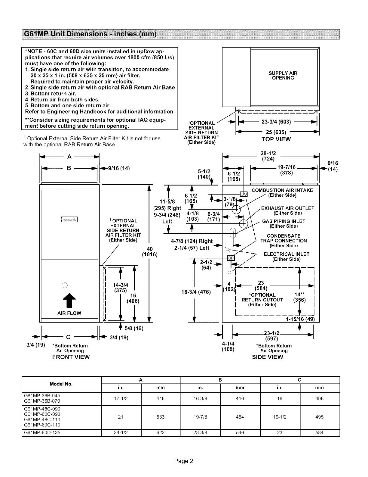
*NOTE - 60C and 60D size units installed in upflow ap-
plications that require air volumes over 1800 cfm (850 L/s)
must have one of the following:
1. Single side return air with transition, to accommodate
20 x 25 x 1 in. (508 x 635 x 25 mm) air filter.
Required to maintain proper air velocity.
2. Single side return air with optional RAB Return Air Base
3. Bottom return air.
4. Return air from both sides.
5. Bottom and one side return air.
Refer to Engineering Handbook for additional information.
**Consider sizing requirements for optional IAQ equip-
ment before cutting side return opening.
1 Optional External Side Return Air Filter Kit is not for use
with the optional NAB Return Air Base.
,,_ A-_
B-_ _-9/16(14)
t
AIR FLOW
SUPPLY AIR
OPENING
_OPTIONAL 23-3/4 (603)
EXTERNAL. I_
SIDE RETURN i_--_ 25 (635)
AIR FILTER KIT TOP VIEW
(Either Side)
t6-1/2
11-5/8 11}5) *-_
(295) Right
28-1/2
J_ (724)
5-112 _I_ 19-7116_
r_ COMBUSTION AIR INTAKE
.... _ _ (Either Side)
( ly \ /EXHAUST AIR OUTLET
9- _/_ Av(Either Side)
_ GASP,P,NG,NLET
_11_ y\ (Either Side)
\.r_ CONDENSATE
L_TRAPCONNECTION
°Oo_ (Either Side)
_ ELECTRICAL INLET
, ,E,, ers, ei
(64) _ ....
I23
1OPTIONAL
EXTERNAL
SIDE RETURN
AIR FILTER KIT
(Either Side)
,o
(1016)
5/8(16)
--J_l- 3/4 (19)
9-3/4 (248) 4-1/8 6-3/4
Left (103) (171)
4-7/8 (124) Right
2-1/4 (57) Left -I_
18-3/4 (476) -I_ {1_2_1_A (584) I
I*OPTIONAL 14"*
I RETURN CUTOUT
I (Either Side)
L
JL--o --I- +-
3/4 (19) *Bottom Return 4-1/4 *Bottom Return
Air Opening (108) Air Opening
FRONT VIEW SIDE VIEW
9/16
91-(14)
A B C
Model No. in. mm in. mm in. mm
G61MP-36B-045
G61MP-36B-070 17-1/2 446 16-3/8 416 16 406
G61 MP-48C-090
G61MP-60C-090 21 533 19-7/8 454 19-1/2 495
G61MP-48C-110
G61MP-60C-110
G61MP-60D-135 24-1/2 622 23-3/8 546 23 584
Page 2
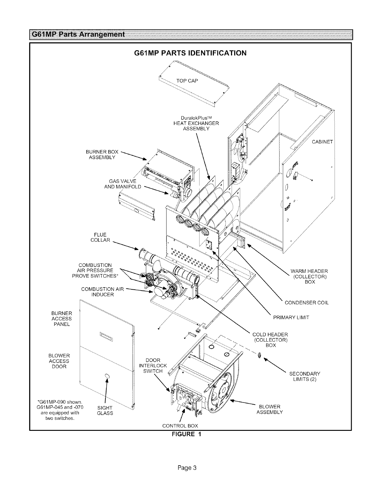
G61MP PARTS IDENTIFICATION
DuralokPlus TM
HEATEXCHANGER
ASSEMBLY
CABINET
GAS VALVE
AND MANIFOLD
FLUE
COLLAR
COMBUSTION
AIR PRESSURE
PROVE SWITCHES*
COMBUSTION AIR
INDUCER
BURNER
ACCESS
PANEL
BLOWER
ACCESS
DOOR
*G61MP-090 shown.
G61MP-045 and -070
are equipped with
two switches.
%
SIGHT
GLASS
DOOR
INTERLOCK
SWITCH
\
CONTROL BOX
FIGURE 1
/
/
/
WARM HEADER
(COLLECTOR)
BOX
CONDENSER COIL
PRIMARY LIMIT
COLD HEADER
(COLLECTOR)
BOX
--.¢ -....SECONDARY
LIMITS (2)
BLOWER
ASSEMBLY
Page 3
TheG61MPgasfurnaceisshippedreadyforinstallationin
theupflow,downflow,horizontalleftairdischargeorhori-
zontalrightairdischargeposition.Thefurnaceisshipped
withthebottompanelinplace.Thebottompanelmustbe
removedif theunitistobeinstalledin upflowapplications
withbottomreturnair.Thebottompanelmustalsobere-
movedanddiscardedinalldownfloworhorizontalapplica-
tions.
Thefurnaceisequippedforinstallationinnaturalgasap-
plications.A conversionkit(orderedseparately)isrequired
foruseinpropane/LPgasapplications.
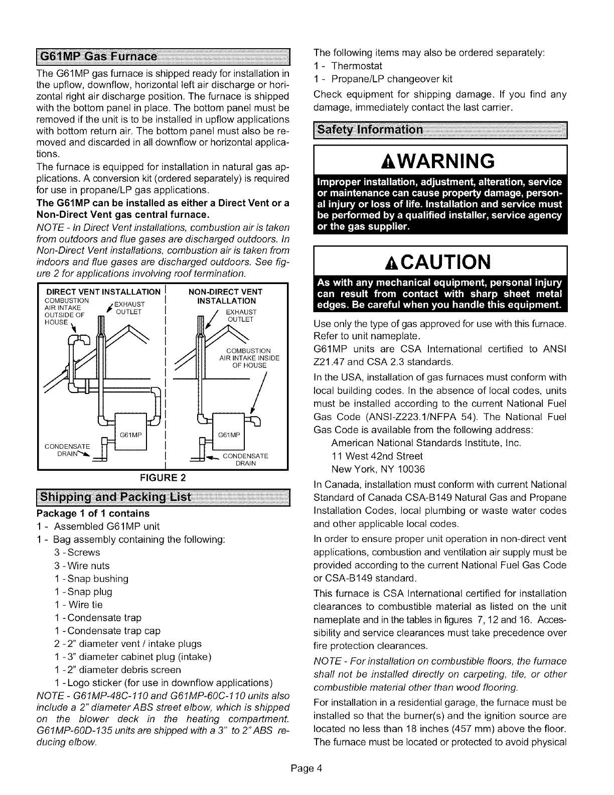
The G61MP can be installed as either a Direct Vent or a
Non-Direct Vent gas central furnace.
NOTE -In Direct Vent installations, combustion air is taken
from outdoors and flue gases are discharged outdoors. In
Non-Direct Vent installations, combustion air is taken from
indoors and flue gases are discharged outdoors. See fig-
ure 2for appfications involving roof termination.
DIRECT VENT INSTALLATION
COMBUSTION EXHAUST
AIR INTAKE OUTLET
OUTSIDE OF
HOUSE _
CONDENSATE
DRAIN"_I,
NON-DIRECT VENT
INSTALLATION
EXHAUST
OUTLET
COMBUSTION
AIR INTAKE INSIDE
OF HOUSE
I
FIGURE 2
CONDENSATE
DRAIN
Package 1 of 1 contains
1 - Assembled G61MP unit
1 - Bag assembly containing the following:
3 - Screws
3 -Wire nuts
1 - Snap bushing
1 - Snap plug
1 - Wire tie
1 - Condensate trap
1 - Condensate trap cap
2 -2" diameter vent /intake plugs
1 - 3" diameter cabinet plug (intake)
1 -2" diameter debris screen
1 -Logo sticker (for use in downflow applications)
NOTE -G61MP-48C-110 and G61MP-60C-110 units also
include a 2" diameter ABS street elbow, which is shipped
on the blower deck in the heating compartment.
G61MP-60D-135 units are shipped with a 3" to 2"ABS re-
ducing elbow.
The following items may also be ordered separately:
1- Thermostat
1 - Propane/LP changeover kit
Check equipment for shipping damage. If you find any
damage, immediately contact the last carrier.
-&WARNING
- CAUTION
Use only the type of gas approved for use with this furnace.
Refer to unit nameplate.
G61MP units are CSA International certified to ANSI
Z21.47 and CSA 2.3 standards.
In the USA, installation of gas furnaces must conform with
local building codes. In the absence of local codes, units
must be installed according to the current National Fuel
Gas Code (ANSl-Z223.1/NFPA 54). The National Fuel
Gas Code is available from the following address:
American National Standards Institute, Inc.
11 West 42nd Street
New York, NY 10036
In Canada, installation must conform with current National
Standard of Canada CSA-B149 Natural Gas and Propane
Installation Codes, local plumbing or waste water codes
and other applicable local codes.
In order to ensure proper unit operation in non-direct vent
applications, combustion and ventilation air supply must be
provided according to the current National Fuel Gas Code
or CSA-B149 standard.
This furnace is CSA International certified for installation
clearances to combustible material as listed on the unit
nameplate and in the tables in figures 7, 12 and 16. Acces-
sibility and service clearances must take precedence over
fire protection clearances.
NOTE- For installation on combustible floors, the furnace
shall not be installed directly on carpeting, tile, or other
combustible material other than wood flooring.
For installation in a residential garage, the furnace must be
installed so that the burner(s) and the ignition source are
located no less than 18 inches (457 mm) above the floor.
The furnace must be located or protected to avoid physical
Page 4
damagebyvehicles.Whenafurnaceisinstalledinapublic
garage,hangar,orotherbuildingthathasahazardousat-
mosphere,thefurnacemustbeinstalledaccordingtorec-
ommendedgoodpracticerequirementsandcurrentNa-
tionalFuelGasCodeorCSAB149standard.
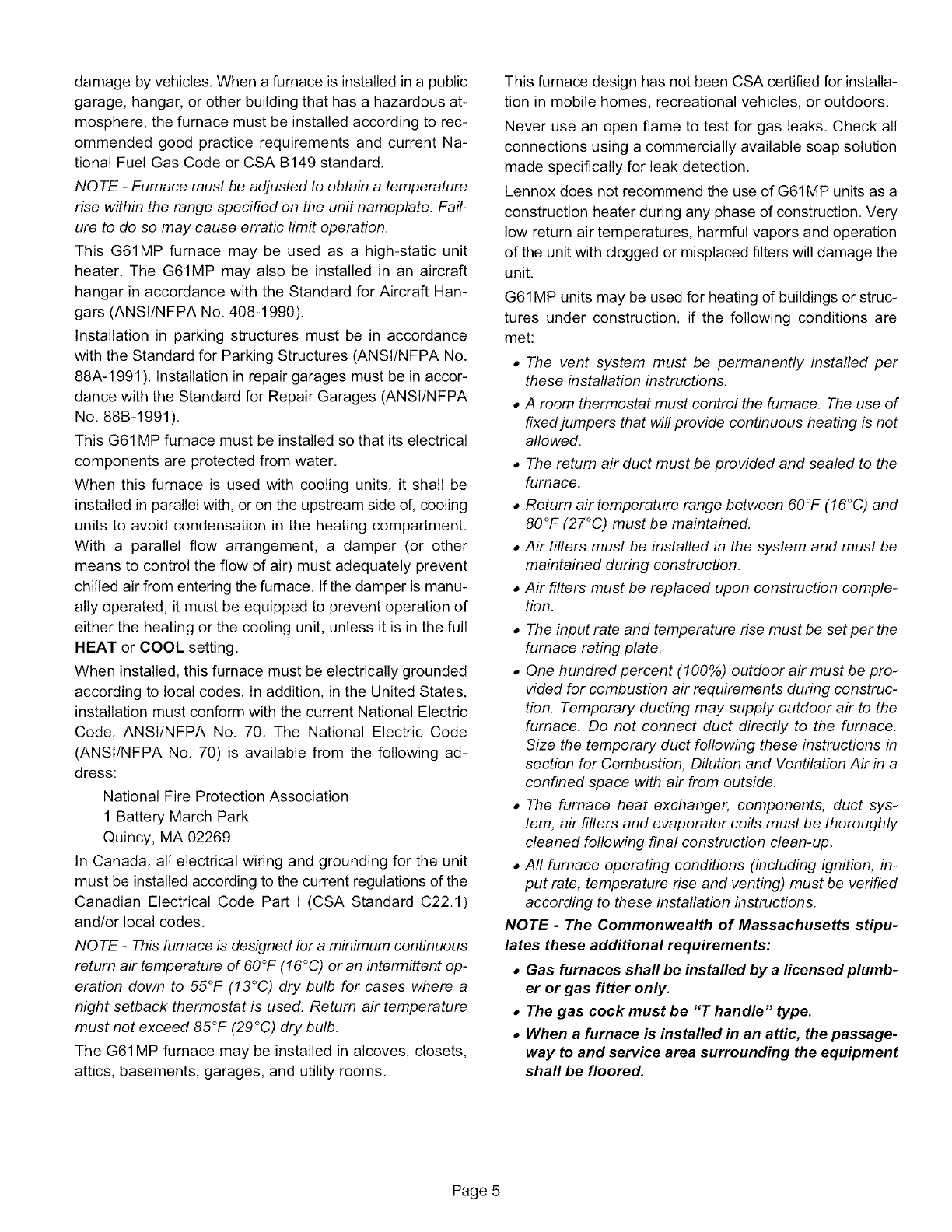
NOTE -Furnace must be adjusted to obtain a temperature
rise within the range specified on the unit nameplate. Fail-
ure to do so may cause erratic limit operation.
This G61MP furnace may be used as a high-static unit
heater. The G61MP may also be installed in an aircraft
hangar in accordance with the Standard for Aircraft Han-
gars (ANSI/NFPA No. 408-1990).
Installation in parking structures must be in accordance
with the Standard for Parking Structures (ANSI/NFPA No.
88A-1991 ). Installation in repair garages must be in accor-
dance with the Standard for Repair Garages (ANSI/NFPA
No. 88B-1991).
This G61MP furnace must be installed so that its electrical
components are protected from water.
When this furnace is used with cooling units, it shall be
installed in parallel with, or on the upstream side of, cooling
units to avoid condensation in the heating compartment.
With a parallel flow arrangement, a damper (or other
means to control the flow of air) must adequately prevent
chilled air from entering the furnace. If the damper is manu-
ally operated, it must be equipped to prevent operation of
either the heating or the cooling unit, unless it is in the full
HEAT or COOL setting.
When installed, this furnace must be electrically grounded
according to local codes. In addition, in the United States,
installation must conform with the current National Electric
Code, ANSI/NFPA No. 70. The National Electric Code
(ANSI/NFPA No. 70) is available from the following ad-
dress:
National Fire Protection Association
1 Battery March Park
Quincy, MA 02269
In Canada, all electrical wiring and grounding for the unit
must be installed according to the current regulations of the
Canadian Electrical Code Part I (CSA Standard C22.1)
and/or local codes.
NOTE -This furnace is designed for a minimum continuous
return air temperature of 60°F (16°C) or an intermittent op-
eration down to 55°F (13°C) dry bulb for cases where a
night setback thermostat is used. Return air temperature
must not exceed 85°F (29 °C) dry bulb.
The G61MP furnace may be installed in alcoves, closets,
attics, basements, garages, and utility rooms.
This furnace design has not been CSA certified for installa-
tion in mobile homes, recreational vehicles, or outdoors.
Never use an open flame to test for gas leaks. Check all
connections using a commercially available soap solution
made specifically for leak detection.
Lennox does not recommend the use of G61MP units as a
construction heater during any phase of construction. Very
low return air temperatures, harmful vapors and operation
of the unit with clogged or misplaced filters will damage the
unit.
G61MP units may be used for heating dbuildings or struc-
tures under construction, if the following conditions are
met:
•The vent system must be permanently installed per
these installation instructions.
• A room thermostat must control the furnace. The use of
fixed jumpers that will provide continuous heating is not
allowed.
• The return air duct must be provided and sealed to the
furnace.
• Return air temperature range between 60°F (16°C) and
80°F (27°C) must be maintained.
• Air filters must be installed in the system and must be
maintained during construction.
• Air filters must be replaced upon construction comple-
tion.
• The inputrate and temperature rise mustbe setperthe
furnace rating plate.
•One hundred percent (100%) outdoor air must be pro-
vided for combustion air requirements during construc-
tion. Temporary ducting may supply outdoor air to the
furnace. Do not connect duct directly to the furnace.
Size the temporary duct following these instructions in
section for Combustion, Dilution and Ventilation Air in a
confined space with air from outside.
• The furnace heat exchanger, components, duct sys-
tem, air filters and evaporator coils must be thoroughly
cleaned following final construction clean-up.
• All furnace operating conditions (including ignition, in-
put rate, temperature rise and venting) must be verified
according to these installation instructions.
NOTE -The Commonwealth of Massachusetts stipu-
lates these additional requirements:
•Gas furnaces shall be installed by a licensedplumb-
er or gas fitter only.
•The gas cock must be "T handle" type.
•When a furnace is installed in an attic, the passage-
way to and service area surrounding the equipment
shall be floored.
Page 5
Theseinstructionsareintendedasageneralguideanddo
notsupersedelocalcodesinanyway Consultauthorities
havingjurisdictionbeforeinstallation
Inadditiontotherequirementsoutlinedpreviously,thefol-
lowinggeneralrecommendationsmustbe considered
wheninstallinga G61MPfurnace:
• Placethefurnaceascloseto thecenterof theairdis-
tributionsystemaspossibleThefurnaceshouldalsobe
locatedclosetothechimneyorventterminationpoint
• Whenthefurnaceisinstalledinnon-directventapplica-
tions,donotinstallthefurnacewheredraftsmightblow
directlyintoit Thiscouldcauseimpropercombustion
andunsafeoperation
• Whenthefurnaceisinstalledinnon-directventapplica-
tions,donotblockthefurnacecombustionairopening
withclothing,boxes,doors,etc Airisneededforproper
combustionandsafeunitoperation
• Whenthefurnaceisinstalledinanatticor otherinsu-
latedspace,keepinsulationawayfromthefurnace
• Whenthe furnaceis installedin an unconditioned
space,considerprovisionsrequiredtopreventfreezing
ofcondensatedrainsystem
CAUTION
-&WARNING
If the G61MP is installed as a Non-Direct Vent Furnace,
follow the guidelines in this section.
NOTE- In Non-Direct Vent installations, combustion air is
taken from indoors and flue gases are discharged out-
doors.
WARNING
In the past, there was no problem in bringing in sufficient
outdoor air for combustion, Infiltration provided all the air
that was needed. In today's homes, tight construction prac-
tices make it necessary to bring in air from outside for com-
bustion, Take into account that exhaust fans, appliance
vents, chimneys, and fireplaces force additional air that
could be used for combustion out of the house, Unless out-
side air is brought into the house for combustion, negative
pressure (outside pressure is greater than inside pressure)
will build to the point that a downdraft can occur in the fur-
nace vent pipe or chimney, As a result, combustion gases
enter the living space creating a potentially dangerous situ-
ation,
In the absence of local codes concerning air for combus-
tion and ventilation, use the guidelines and procedures in
this section to install G61MP furnaces to ensure efficient
and safe operation You must consider combustion air
needs and requirements for exhaust vents and gas piping
A portion of this information has been reprinted with per-
mission from the National Fuel Gas Code (ANSI-
Z223 1/NFPA 54) This reprinted material is not the com-
plete and official position of the ANSI on the referenced
subject, which is represented only by the standard in its en-
tirety
In Canada, refer to the standard CSA B149 installation
codes
Page 6
ACAUTION
All gas-fired appliances require air for the combustion pro-
cess. If sufficient combustion air is not available, the fur-
nace or other appliance will operate inefficiently and un-
safely. Enough air must be provided to meet the needs of
all fuel-burning appliances and appliances such as ex-
haust fans which force air out of the house. When fire-
places, exhaust fans, or clothes dryers are used at the
same time as the furnace, much more air is required to en-
sure proper combustion and to prevent a downdraft. Insuf-
ficient air causes incomplete combustion which can result
in carbon monoxide.
In addition to providing combustion air, fresh outdoor air di-
lutes contaminants in the indoor air. These contaminants
may include bleaches, adhesives, detergents, solvents
and other contaminants which can corrode furnace compo-
nents.
The requirements for providing air for combustion and ven-
tilation depend largely on whether the furnace is installed in
an unconfined or a confined space.
Unconfined Space
An unconfined space is an area such as a basement or
large equipment room with a volume greater than 50 cubic
feet (1.42 m3) per 1,000 Btu (.29 kW) per hour of the com-
bined input rating of all appliances installed in that space.
This space also includes adjacent rooms which are not
separated by a door. Though an area may appear to be un-
confined, it might be necessary to bring in outdoor air for
combustion if the structure does not provide enough air by
infiltration. If the furnace is located in a building of tight
construction with weather stripping and caulking around
the windows and doors, follow the procedures in the air
from outside section.
Confined Space
A confined space is an area with a volume less than 50 cu-
bic feet (1.42 m3) per 1,000 Btu (.29 kW) per hour of the
com-bined input rating of all appliances installed in that
space. This definition includes furnace closets or small
equipment rooms.
When the furnace is installed so that supply ducts carry air
circulated by the furnace to areas outside the space con-
taining the furnace, the return air must be handled by ducts
which are sealed to the furnace casing and which terminate
outside the space containing the furnace. This is especially
important when the furnace is mounted on a platform in a
confined space such as a closet or small equipment room.
Even a small leak around the base of the unit at the platform
or at the return air duct connection can cause a potentially
dangerous negative pressure condition. Air for combustion
and ventilation can be brought into the confined space ei-
ther from inside the building or from outside.
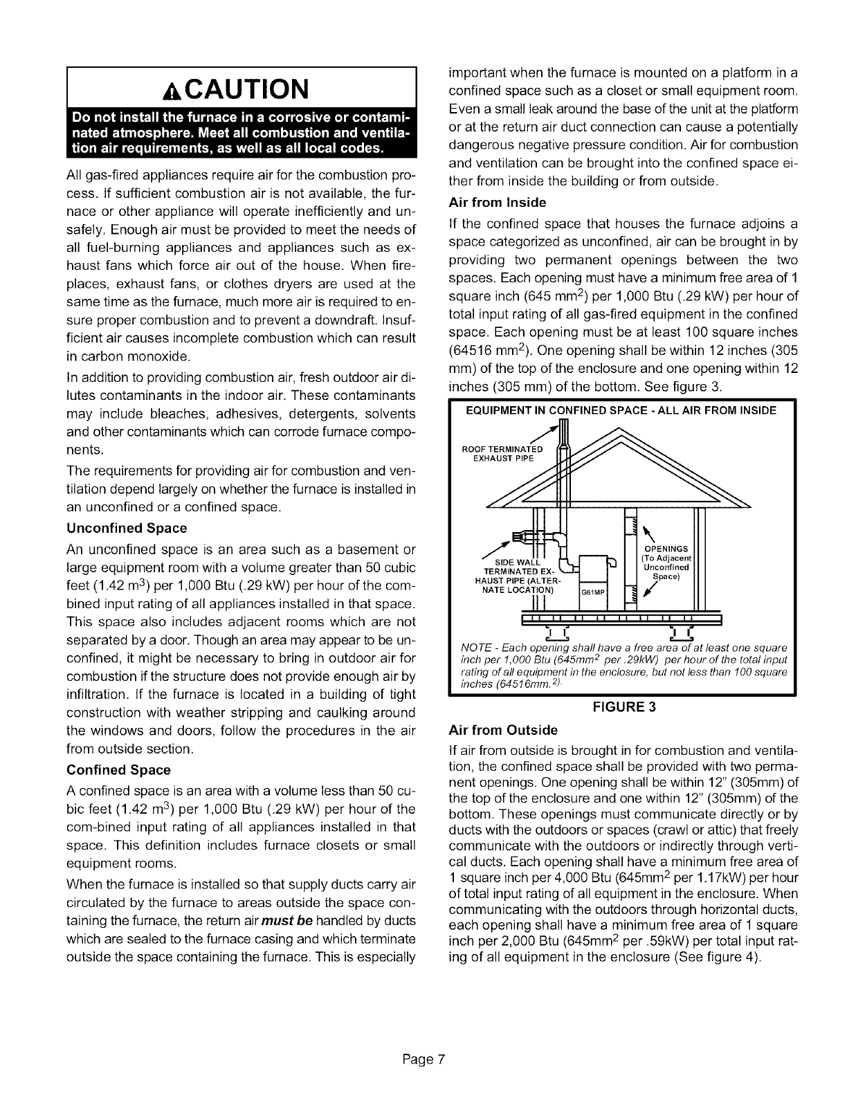
Air from Inside
If the confined space that houses the furnace adjoins a
space categorized as unconfined, air can be brought in by
providing two permanent openings between the two
spaces. Each opening must have a minimum free area of 1
square inch (645 mm2) per 1,000 Btu (.29 kW) per hour of
total input rating of all gas-fired equipment in the confined
space. Each opening must be at least 100 square inches
(64516 mm2). One opening shall be within 12 inches (305
mm) of the top of the enclosure and one opening within 12
inches (305 mm) of the bottom. See figure 3.
EQUIPMENT IN CONFINED SPACE -ALL AIR FROM INSIDE
ROOF TERMINA] ED_lr
EXHAUST PIPE
'-, _ OPENINGS
•-- (To Adjacent
SIDE WALL _1 Unconfined
ERMINATED EX=
UST PIPE (ALTER- -- __pace)
ATE LOCATION) G61MP Y
III
I I I I I I I I I I I I I I I I I I
' h ¢"l ¢'
NOTE -Each opening shall havo a free area of at least ono square
inch per 1,000 Btu (645mm 2per .29kW) per hour of the total input
rating of all equipment in the enclosure, but not less than 100 square
inches (64516mm. 2).
FIGURE 3
Air from Outside
If air from outside is brought in for combustion and ventila-
tion, the confined space shall be provided with two perma-
nent openings. One opening shall be within 12" (305mm) of
the top of the enclosure and one within 12" (305mm) dthe
bottom. These openings must communicate directly or by
ducts with the outdoors or spaces (crawl or attic) that freely
communicate with the outdoors or indirectly through verti-
cal ducts. Each opening shall have a minimum free area of
1 square inch per 4,000 Btu (645mm 2 per 1.17kW) per hour
of total input rating of all equipment in the enclosure. When
communicating with the outdoors through horizontal ducts,
each opening shall have a minimum free area of 1 square
inch per 2,000 Btu (645mm 2 per .59kW) per total input rat-
ing of all equipment in the enclosure (See figure 4).
Page 7
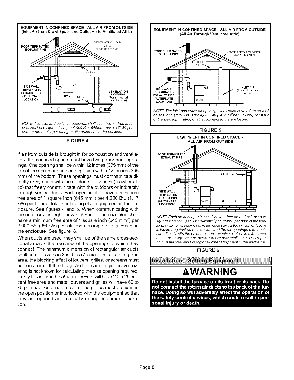
EQUIPMENT IN CONFINED SPACE - ALL AIR FROM OUTSIDE
(Inlet Air from Crawl Space and Outlet Air to Ventilated Attic)
VENTILATION LOU-
ROOF TERMINATED VERS
EXHAUST PIPE (Each end of attic)
\ II I
OUTLET
AIR
IINATED
JST PIPE VENTIL
LOU_.
("IRNATE G61MP INLET (For un
ATION) AIR _.,., crawl .'pace)
/
I_1 i" rrrm
NOTE-The inlet and outlet air openings shall each have a free area
of at least one square inch per 4,000 Btu (645mm2per 1.17kW) per
hour of the total input rating of all equipment in the enclosure.
FIGURE 4
If air from outside is brought in for combustion and ventila-
tion, the confined space must have two permanent open-
ings, One opening shall be within 12 inches (305 mm) of the
top of the enclosure and one opening within 12 inches (305
mm) of the bottom, These openings must communicate di-
rectly or by ducts with the outdoors or spaces (crawl or at-
tic) that freely communicate with the outdoors or indirectly
through vertical ducts. Each opening shall have a minimum
free area of 1 square inch (645 mm 2) per 4,000 Btu (1,17
kW) per hour of total input rating of all equipment in the en-
closure, See figures 4 and 5. When communicating with
the outdoors through horizontal ducts, each opening shall
have a minimum free area of 1 square inch (645 mm2) per
2,000 Btu (.56 kW) per total input rating of all equipment in
the enclosure, See figure 6,
When ducts are used, they shall be of the same cross-sec-
tional area as the free area of the openings to which they
connect. The minimum dimension of rectangular air ducts
shall be no less than 3 inches (75 mm). In calculating free
area, the blocking effect of louvers, grilles, or screens must
be considered. If the design and free area of protective cov-
ering is not known for calculating the size opening required,
it may be assumed that wood louvers will have 20 to 25 per-
cent free area and metal louvers and grilles will have 60 to
75 percent free area. Louvers and grilles must be fixed in
the open position or interlocked with the equipment so that
they are opened automatically during equipment opera-
tion,
EQUIPMENT IN CONFINED SPACE - ALL AIR FROM OUTSIDE
(All Air Through Ventilated Attic)
7
ROOF TERMINATED VENTILATION LOUVERS
EXHAUST PIPE (Each end of attic)
TERMINATED
EXHAUSTPtPE
(ALTERNATE
LOCATION)
INLET AIR
(Ends 12"above
bottom)
NOTE-The inlet and outlet air openings shall each have a free area of
at least one square inch per 4,000 Btu (645mm2per 1.17kW) per hour
of the total input rating of all equipment in the enclosure.
FIGURE 5
EQUIPMENT IN CONFINED SPACE -
ALL AIR FROM OUTSIDE
ROOF TERMINATED
EXHAUST PIPE
SIDE WALL
TERMINATED
EXHAUSTPtPE
(ALTERNATE
LOCATION)
NOTE-Each air duct opening shall have a free area of at least one
square inch per 2,000 Btu (645mm2per. 59kW) per hour of the total
input rating of all equipment in the enclosure, ff the equipment room
is located against an outside wall and the air openings communi-
cate directly with the outdoors, each opening shall have a free area
of at least 1 square inch per 4, 000 Btu (645mm 2per 1.17kW) per
hour of the total input rating of all other equipment in the enclosure.
FIGURE 6
I&WARNING I
Page 8
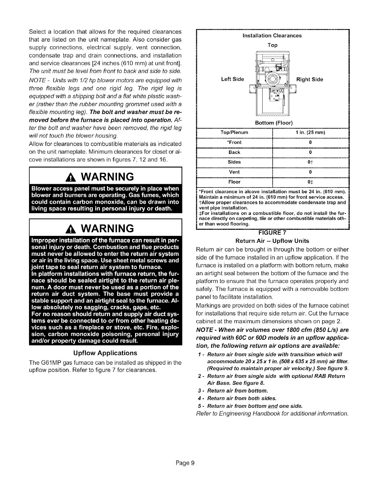
Selecta locationthatallowsfor therequiredclearances
thatarelistedontheunitnameplate.Alsoconsidergas
supplyconnections,electricalsupply,ventconnection,
condensatetrapanddrainconnections,andinstallation
andserviceclearances[24inches(610mm)atunitfront].
The unit must be level from front to back and side to side.
NOTE- Units with 1/2 hp blower motors are equipped with
three flexible legs and one rigid leg. The rigid leg is
equipped with a shipping bolt and a flat white plastic wash-
er (rather than the rubber mounting grommet used with a
flexible mounting leg). The bolt and washer must be re-
moved before the furnace is placed into operation. Af-
ter the bolt and washer have been removed, the rigid leg
will not touch the blower housing.
Allow for clearances to combustible materials as indicated
on the unit nameplate. Minimum clearances for closet or al-
cove installations are shown in figures 7, 12 and 16.
WARNING
AWARNING
Upflow Applications
The G61MP gas furnace can be installed as shipped in the
upflow position. Refer to figure 7 for clearances.
Installation Clearances
Top
Left Side Right Side
J
Bottom (Floor)
............................................... T...............................................
Top/Plenum i1 in. (25 ram)
t
*Front iO
.-................... ....................T..............................................
..'.....................-.........................f...............................................I
Vent i O
=
Floor I O:_
*Front clearance in alcove installation must be 24 in. (610 ram).
Maintain a minimum of 24 in. (610 ram) for front service access.
tAllow proper clearances to accommodate condensate trap and
vent pipe installation.
! :_For installations on acombustible floor, do not install the fur-
inace directly on carpeting, tile or other combustible materials oth-
i er than wood flooring.
=================================================================================================
FIGURE 7
Return Air -- Upflow Units
Return air can be brought in through the bottom or either
side of the furnace installed in an upflow application. If the
furnace is installed on a platform with bottom return, make
an airtight seal between the bottom of the furnace and the
platform to ensure that the furnace operates properly and
safely. The furnace is equipped with a removable bottom
panel to facilitate installation.
Markings are provided on both sides of the furnace cabinet
for installations that require side return air. Cut the furnace
cabinet at the maximum dimensions shown on page 2.
NOTE -When air volumes over 1800 cfm (850 L/s) are
required with 60C or 60D models in an upflow applica-
tion, the following return air options are available:
1-Return air from single side with transition which will
accommodate 20 x 25 x I in. (508 x 635 x 25 ram) air filter.
(Required to maintain proper air velocity.) See figure 9.
2-Return air from single side with optional RAB Return
Air Base. See figure 8.
3-Return air from bottom.
4-Return air from both sides.
5-Return air from bottom and one side.
Refer to Engineering Handbook for additional information.
Page 9
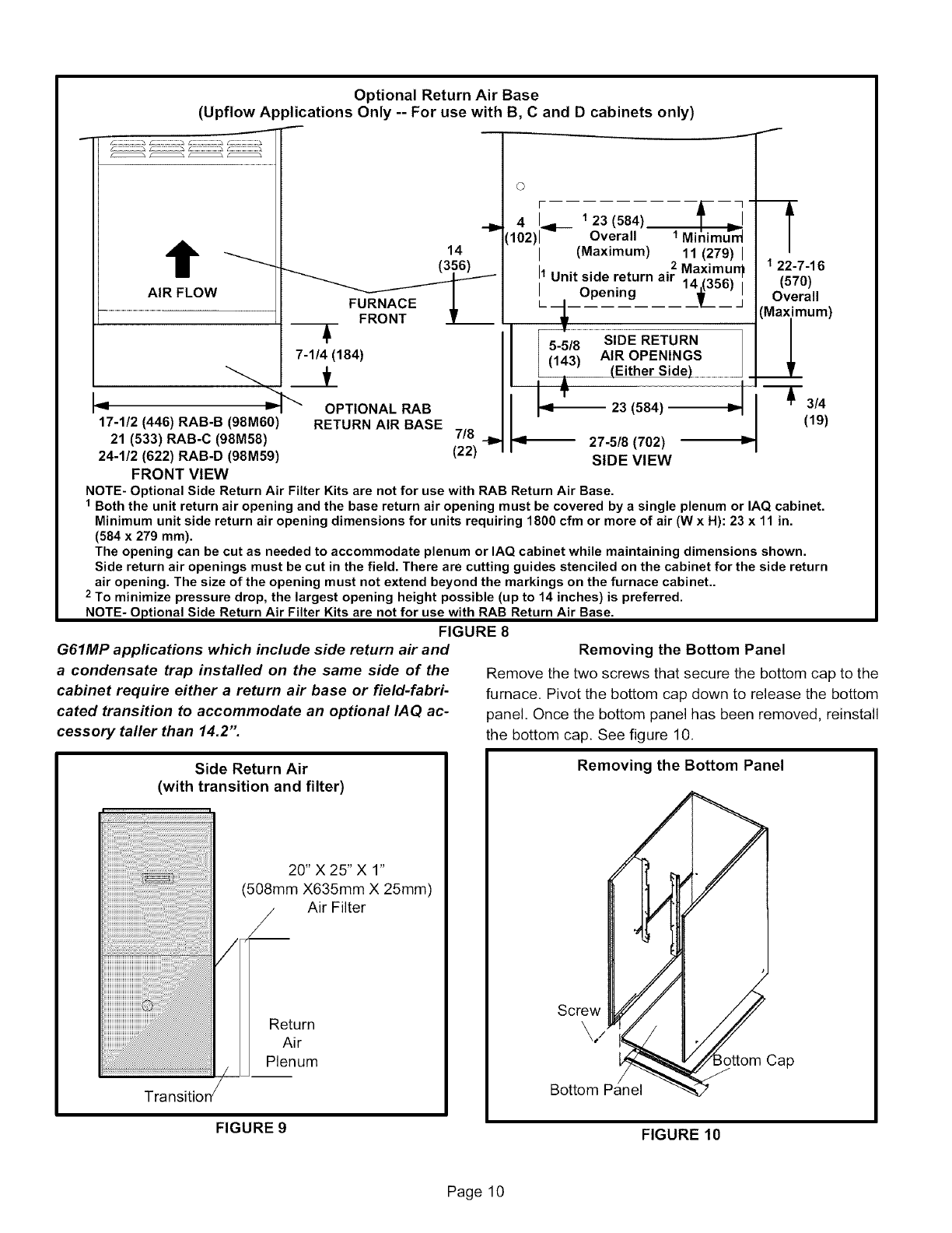
Optional Return Air Base
(Upflow Applications Only -- For use with B, C and D cabinets only)
J
f .............. _ f..............
t
AIR FLOW
--D
14
FURNACE J,
_- FRONT
7-1/4 (184)
'---. 1
_I ''_ OPTIONAL RAB
17-1/2 (446) RAB-B (98M60) RETURN AIR BASE
21 (533) RAB-C (98M58) 7/8 .__
24-1/2 (622) RAB-D (98M59) (22)
FRONT VIEW
©
r
4 I 231584)
(102)1_l-- Overall 1Mihimu"-_
(Maximum) 11 (279) I
2Maximurq
Unit side return airopening14_5.6)/__
5-5/8
(143)
91_ 23 (584)
f
J
122-7-16
(570)
Overall
Maximum)
_l
--3/4
(19)
4-- 27-5/8 (702)
SIDE VIEW
NOTE- Optional Side Return Air Filter Kits are not for use with RAB Return Air Base.
1 Both the unit return air opening and the base return air opening must be covered by a single plenum or IAQ cabinet.
Minimum unit side return air opening dimensions for units requiring 1800 cfm or more of air (W x H): 23 x 11 in.
(584 x 279 mm).
The opening can be cut as needed to accommodate plenum or IAQ cabinet while maintaining dimensions shown.
Side return air openings must be cut in the field. There are cutting guides stenciled on the cabinet for the side return
air opening. The size of the opening must not extend beyond the markings on the furnace cabinet..
2 To minimize pressure drop, the largest opening height possible (up to 14 inches) is preferred.
NOTE- Optional Side Return Air Filter Kits are not for use with RAB Return Air Base.
FIGURE 8
G61MP applications which include side return air and
a condensate trap installed on the same side of the
cabinet require either a return air base or field-fabri-
cated transition to accommodate an optional IAQ ac-
cessory taller than 14.2".
Side Return Air
(with transition and filter)
20" X 25" X 1"
(508mm X635mm X 25mm)
Air Filter
Return
Air
Plenum
Removing the Bottom Panel
Remove the two screws that secure the bottom cap to the
furnace. Pivot the bottom cap down to release the bottom
panel, Once the bottom panel has been removed, reinstall
the bottom cap. See figure 10.
Removing the Bottom Panel
Screw
\/
Bottom
ottom Cap
FIGURE 9 FIGURE 10
Page 10
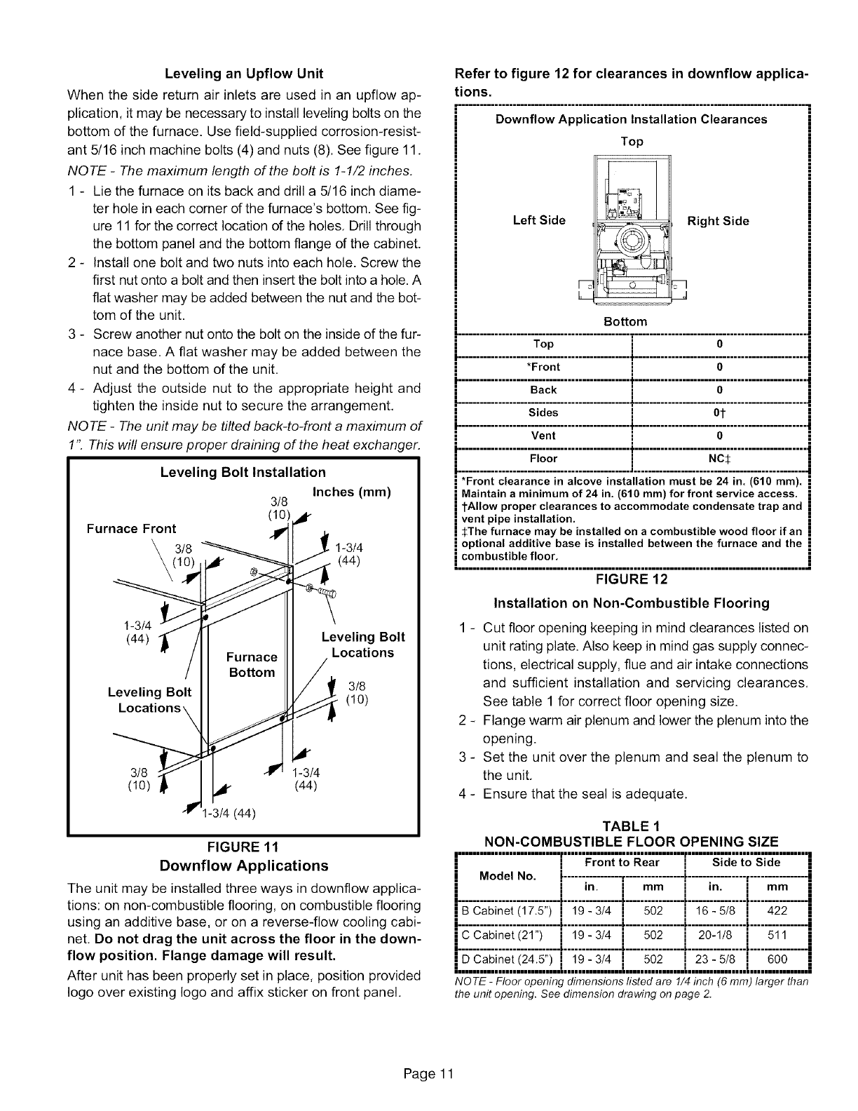
Levelingan Upflow Unit
When the side return air inlets are used in an upflow ap-
plication, it may be necessary to install leveling bolts on the
bottom of the furnace. Use field-supplied corrosion-resist-
ant 5/16 inch machine bolts (4) and nuts (8). See figure 11.
NOTE -The maximum length of the bolt is 1-1/2 inches.
1 - Lie the furnace on its back and drill a 5/16 inch diame-
ter hole in each corner of the furnace's bottom. See fig-
ure 11 for the correct location of the holes. Drill through
the bottom panel and the bottom flange of the cabinet.
2 - Install one bolt and two nuts into each hole. Screw the
first nut onto a bolt and then insert the bolt into a hole. A
flat washer may be added between the nut and the bot-
tom of the unit.
3 - Screw another nut onto the bolt on the inside of the fur-
nace base. A flat washer may be added between the
nut and the bottom of the unit.
4 - Adjust the outside nut to the appropriate height and
tighten the inside nut to secure the arrangement.
NOTE -The unit may be tilted back-to-front a maximum of
1". This will ensure proper draining of the heat exchanger.
Leveling Bolt Installation
Inches (ram)
3/8
Furnace Front _¢
3/8 1-3/4
(44)
1-3/4
(44)
Leveling Bolt
Furnace
Bottom
Leveling Bolt
Locations
3/8
(10)
3/8 1-3/4
(10) (44)
I-3/4 (44)
FIGURE 11
Downflow Applications
The unit may be installed three ways in downflow applica-
tions: on non-combustible flooring, on combustible flooring
using an additive base, or on a reverse-flow cooling cabi-
net. Do not drag the unit across the floor in the down-
flow position. Flange damage will result.
After unit has been properly set in place, position provided
logo over existing logo and affix sticker on front panel.
Refer to figure 12 for clearances in downflow applica-
tions.
•............................................................................................... q
Downflow Application Installation Clearances
Left Side
Top
Right Side
J
Bottom
&,1
............................................... T...............................................
Top i O
*Front IO
."................... ....................T..............................................
Sides i 01"
]
Vent i O
............................................... t ................................................
Floor i NC_:
*Front clearance in alcove installation must be 24 in. (616 ram).
Maintain a minimum of 24 in. (610 ram) for front service access.
tAllow proper clearances to accommodate condensate trap and
vent pipe installation.
_:The furnace may be installed on a combustible wood floor if an
i optional additive base is installed between the furnace and the
i combustible floor.
=================================================================================================
FIGURE 12
Installation on Non-Combustible Flooring
1 - Cut floor opening keeping in mind clearances listed on
unit rating plate. Also keep in mind gas supply connec-
tions, electrical supply, flue and air intake connections
and sufficient installation and servicing clearances.
See table 1 for correct floor opening size.
2 - Flange warm air plenum and lower the plenum into the
opening.
3 - Set the unit over the plenum and seal the plenum to
the unit.
4 - Ensure that the seal is adequate.
TABLE 1
NON-COMBUSTIBLE FLOOR OPENING SIZE
i............................[...... ......[...... ........i
iModel No. _................................. _.................................
iii i•
i"i i "i •
I In. I mm I In. I mm l
I, ,I ,I -t., t.
jBCabinet(17.5") i19-3/4, ,i 502 ,i 16-5/8 ,i 422 j
I, ,I ,I -t., t.
jCCabinet(21") ,i 19-3/4 ,i 502 ,i 20-1/8 ,i 511 j
i, ,I ,I -t., t.
' . " -
• DCabmet(245) , 19 3/4 , 502 , 23 5/8 , 600 •
i............................[................L................[................[................i
NOTE -Floor opening dimensions listed are 1/4 inch (6 mm) larger than
the unit opening. See dimension drawing on page 2.
Page 11
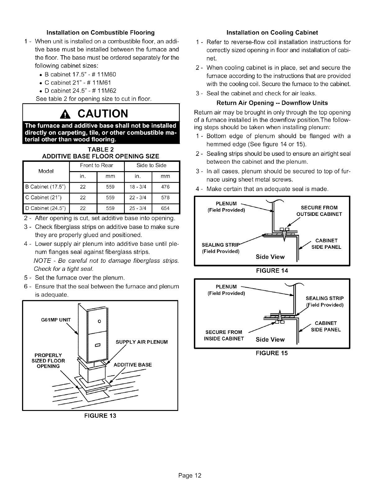
Installation on Combustible Flooring
1 - When unit is installed on a combustible floor, an addi-
tive base must be installed between the furnace and
the floor. The base must be ordered separately for the
following cabinet sizes:
• B cabinet 17,5" - # 11M60
• C cabinet21"-# 11M61
• D cabinet 24,5" - # 11M62
See table 2 for opening size to cut in floor.
Ak CAUTION
TABLE 2
ADDITIVE BASE FLOOR OPENING SIZE
Model mm
B Cabinet (17.5") 476
C Cabinet (21") 578
D Cabinet (24.5") 654
Frontto Rear
in. mm
22 559
22 559
22 559
Side to Side
in.
18 - 3/4
22 - 3/4
25 - 3/4
2 - After opening is cut, set additive base into opening.
3 - Check fiberglass strips on additive base to make sure
they are properly glued and positioned.
4 - Lower supply air plenum into additive base until ple-
num flanges seal against fiberglass strips.
NOTE -Be careful not to damage fiberglass strips.
Check for a tight seal.
5 - Set the furnace over the plenum.
6-Ensure that the seal between the furnace and plenum
is adequate.
G61MP UNIT_ __T
SUPPLY AIR PLENUM
PROPERLY R ,VEBASE
FIGURE 13
Installation on Cooling Cabinet
1 - Refer to reverse-flow coil installation instructions for
correctly sized opening in floor and installation of cabi-
net,
2 - When cooling cabinet is in place, set and secure the
furnace according to the instructions that are provided
with the cooling coil, Secure the furnace to the cabinet,
3 - Seal the cabinet and check for air leaks,
Return Air Opening -- Downflow Units
Return air may be brought in only through the top opening
of a furnace installed in the downflow position.The follow-
ing steps should be taken when installing plenum:
1 - Bottom edge of plenum should be flanged with a
hemmed edge (See figure 14 or 15).
2 - Sealing strips should be used to ensure an airtight seal
between the cabinet and the plenum.
3 - In all cases, plenum should be secured to top of fur-
nace using sheet metal screws,
4 - Make certain that an adequate seal is made,
PLENUM ---,..,._ I_1_ "_
(Field Provided) _ SECURE FROM
•_..............__UTSI DE CABINET
/v II / CABINET
SEAL,NGSTR, IIJ S,DEPANEL
(Field Provided) ...... II
Side View II
FIGURE 14
PLENUM
(Field Provid ed_"_"_---.._
SECUREFROM
INSIDE CABINET Side View
SEALING STRIP
ield Provided)
/CABINET
,SIDE PANEL
FIGURE 15
Page 12
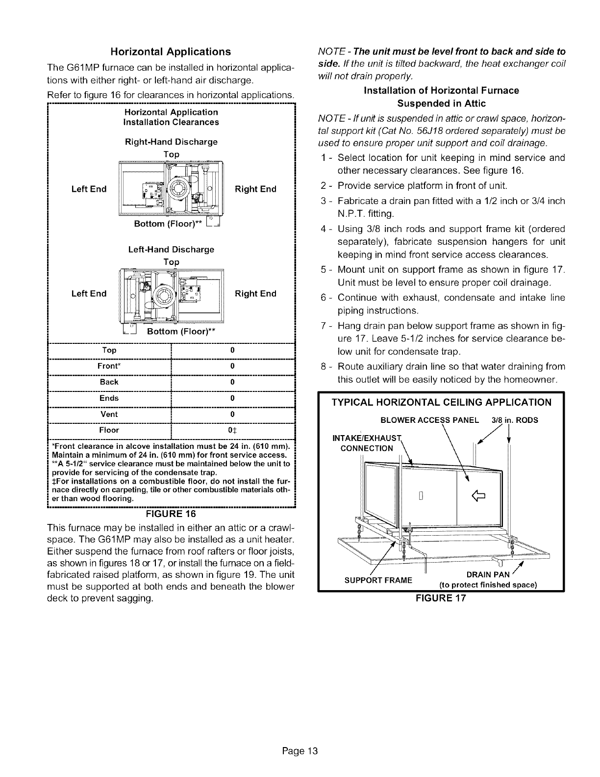
Horizontal Applications
The G61MP furnace can be installed in horizontal applica-
tions with either right- or left-hand air discharge.
Refer to figure 16 for clearances in horizontal applications,
H===================mmmmmmHHHmmmmmmHHHmmmmmmHHHmmmmmmHHHm.
Horizontal Application
Installation Clearances
Right-Hand Discharge
Top
Left End Right End
Left-Hand Discharge
Top
Left End Right End
Top ] O
i................... ron;:...................i.............................................i
Back 1O
".................... ....................i"..............................................
i
Vent !o
=
...................." oor"...................T.....................;;.......................
| ............................................... _ ................................................
*Front clearance in alcove installation must be 24 in. (610 ram).
Maintain a minimum of 24 in. (610 ram) for front service access.
**A 5-1/2" service clearance must be maintained below the unit to
provide for servicing of the condensate trap.
_:For installations on a combustible floor, do not install the fur-
nace directly on carpeting, tile or other combustible materials oth-
er than wood flooring.
FIGURE 16
This furnace may be installed in either an attic or a crawl-
space. The G61MP may also be installed as a unit heater.
Either suspend the furnace from roof rafters or floor joists,
as shown in figures 18 or 17, or install the furnace on a field-
fabricated raised platform, as shown in figure 19. The unit
must be supported at both ends and beneath the blower
deck to prevent sagging,
NOTE -The unit must be level front to back and side to
side. If the unit is tilted backward, the heat exchanger coil
will not drain properly,
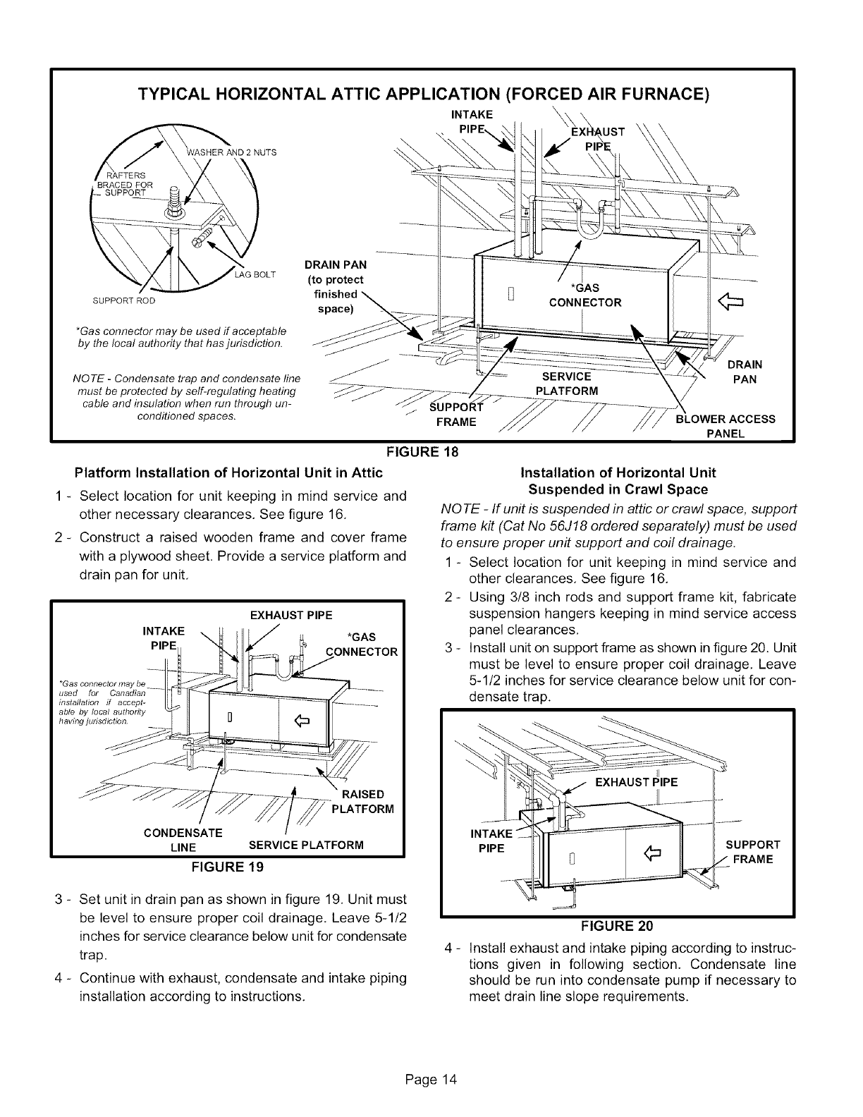
Installation of Horizontal Furnace
Suspended in Attic
NOTE -If unit is suspended in attic or crawl space, horizon-
tal support kit (Cat No. 56J18 ordered separately) must be
used to ensure proper unit support and coil drainage.
1 - Select location for unit keeping in mind service and
other necessary clearances. See figure 16.
2 - Provide service platform in front of unit,
3 - Fabricate a drain pan fitted with a 1/2 inch or 3/4 inch
N,P,T, fitting.
4- Using 3/8 inch rods and support frame kit (ordered
separately), fabricate suspension hangers for unit
keeping in mind front service access clearances.
5 - Mount unit on support frame as shown in figure 17,
Unit must be level to ensure proper coil drainage,
6- Continue with exhaust, condensate and intake line
piping instructions,
7 - Hang drain pan below support frame as shown in fig-
ure 17. Leave 5-1/2 inches for service clearance be-
low unit for condensate trap,
8 - Route auxiliary drain line so that water draining from
this outlet will be easily noticed by the homeowner,
TYPICAL HORIZONTAL CEILING APPLICATION
BLOWER ACCESS PANEL 3/8 in. RODS
CONNECTION
SUPPORTFRAME
DRAIN PAN /
(to protect finished space)
FIGURE 17
Page 13
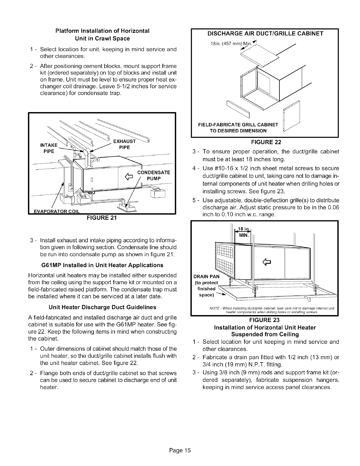
TYPICAL HORIZONTAL ATTIC APPLICATION (FORCED AIR FURNACE)
INTAKE \
SAFTERS
BRACED FOR
SUPPORT
WASHER AND 2 NUTS
\
LAG BOLT
SUPPORT ROD
*Gas connector may be used if acceptable
by the local authority that has jurisdiction.
NOTE - Condensate trap and condensate line
must be protected by self-regulating heating
cable and insulation when run through un-
conditioned spaces.
DRAIN PAN
(to protect
finished
space)
Platform Installation of Horizontal Unit in Attic
j SUPPORT
FRAME
FIGURE 18
1 - Select location for unit keeping in mind service and
other necessary clearances, See figure 16,
2 - Construct a raised wooden frame and cover frame
with a plywood sheet, Provide a service platform and
drain pan for unit,
INTAKE
*Gas connector may be
used for Canadian
installation ff accept-
able by local authority
having jurisdiction.
EXHAUST PIPE
*GAS
CONNECTOR
RAISED
CONDENSATE
LINE SERVICE PLATFORM
FIGURE 19
3 - Set unit in drain pan as shown in figure 19, Unit must
be level to ensure proper coil drainage, Leave 5-1/2
inches for service clearance below unit for condensate
trap.
4 - Continue with exhaust, condensate and intake piping
installation according to instructions.
SERVICE
PLATFORM
DRAIN
PAN
BLOWER ACCESS
PANEL
Installation of Horizontal Unit
Suspended in Crawl Space
NO TE -If unit is suspended in attic or crawl space, support
frame kit (Cat No 56J18 ordered separately) must be used
to ensure proper unit support and coil drainage.
1 - Select location for unit keeping in mind service and
other clearances, See figure 16,
2 - Using 3/8 inch rods and support frame kit, fabricate
suspension hangers keeping in mind service access
panel clearances,
3 - Install unit on support frame as shown in figure 20. Unit
must be level to ensure proper coil drainage, Leave
5-1/2 inches for service clearance below unit for con-
densate trap.
INTAKE"
PIPE SUPPORT
FRAME
FIGURE 20
4 - Install exhaust and intake piping according to instruc-
tions given in following section. Condensate line
should be run into condensate pump if necessary to
meet drain line slope requirements.
Page 14
Platform Installation of Horizontal
Unit in Crawl Space
1 - Select location for unit, keeping in mind service and
other clearances,
2 - After positioning cement blocks, mount support frame
kit (ordered separately) on top of blocks and install unit
on frame. Unit must be level to ensure proper heat ex-
changer coil drainage. Leave 5-1/2 inches for service
clearance) for condensate trap.
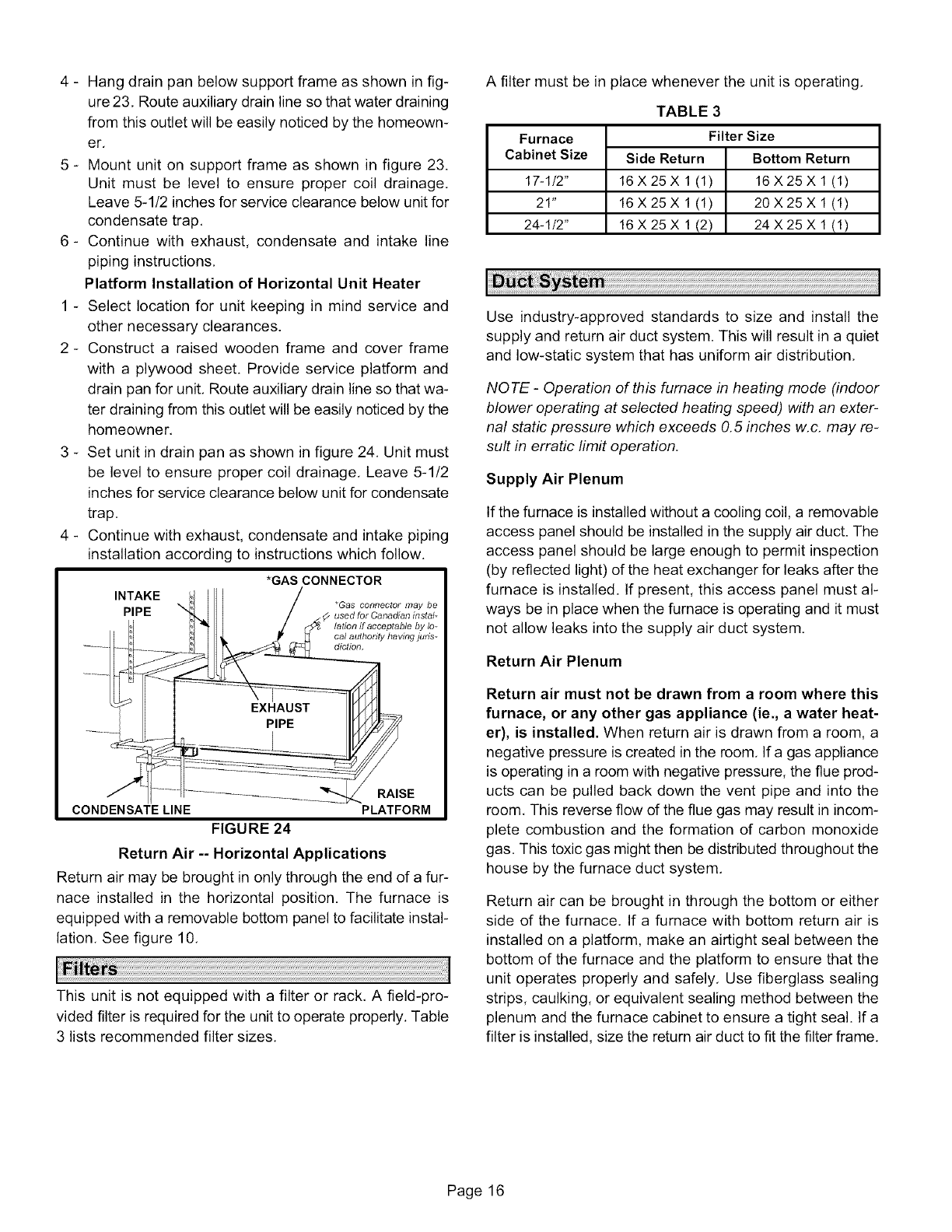
FIGURE 21
DISCHARGE AIR DUCT/GRILLE CABINET
18in, (457 mm) k ql
FIELD-FABRICATE GRILL CABINET
TO DESIRED DIMENSION
FIGURE 22
3- To ensure proper operation, the duct/grille cabinet
must be at least 18 inches long.
4 - Use #10-16 x 1/2 inch sheet metal screws to secure
duct/grille cabinet to unit, taking care not to damage in-
ternal components of unit heater when drilling holes or
installing screws. See figure 23,
5 - Use adjustable, double-deflection grille(s) to distribute
discharge air. Adjust static pressure to be in the 0.06
inch to 0.10 inch w.c. range.
3 - Install exhaust and intake piping according to informa-
tion given in following section, Condensate line should
be run into condensate pump as shown in figure 21.
G61MP Installed in Unit Heater Applications
Horizontal unit heaters may be installed either suspended
from the ceiling using the support frame kit or mounted on a
field-fabricated raised platform. The condensate trap must
be installed where it can be serviced at a later date,
Unit Heater Discharge Duct Guidelines
A field-fabricated and installed discharge air duct and grille
cabinet is suitable for use with the G61MP heater. See fig-
ure 22, Keep the following items in mind when constructing
the cabinet,
1 - Outer dimensions of cabinet should match those of the
unit heater, so the duct/grille cabinet installs flush with
the unit heater cabinet, See figure 22,
2 - Flange both ends of duct/grille cabinet so that screws
can be used to secure cabinet to discharge end of unit
heater.
DRAIN PAN
(to protect
finished
space)
NOTE -When installing duct/grille cabinet, take care not to damage internal unit
heater components when drilling holes or instalhng screws.
FIGURE 23
Installation of Horizontal Unit Heater
Suspended from Ceiling
1 - Select location for unit keeping in mind service and
other clearances.
2 - Fabricate a drain pan fitted with 1/2 inch (13 mm) or
3/4 inch (19 mm) N.P.T. fitting.
3 - Using 3/8 inch (9 mm) rods and support frame kit (or-
dered separately), fabricate suspension hangers,
keeping in mind service access panel clearances.
Page 15
4 - Hangdrainpanbelowsupportframeasshowninfig-
ure23,Routeauxiliarydrainlinesothatwaterdraining
fromthisoutletwillbeeasilynoticedbythehomeown-
er,
5- Mountunitonsupportframeasshowninfigure23.
Unitmustbelevelto ensurepropercoildrainage,
Leave5-1/2inchesforserviceclearancebelowunitfor
condensatetrap,
6- Continuewithexhaust,condensateand intakeline
pipinginstructions,
PlatformInstallationof HorizontalUnitHeater
1- Selectlocationfor unitkeepingin mindserviceand
othernecessaryclearances.
2 - Constructa raisedwoodenframeandcoverframe
witha plywoodsheet.Provideserviceplatformand
drainpanforunit,Routeauxiliarydrainlinesothatwa-
terdrainingfromthisoutletwillbeeasilynoticedbythe
homeowner,
3- Setunitindrainpanasshowninfigure24,Unitmust
beleveltoensurepropercoildrainage,Leave5-1/2
inchesforserviceclearancebelowunitforcondensate
trap.
4 - Continuewithexhaust,condensateandintakepiping
installationaccordingtoinstructionswhichfollow.
*GAS CONNECTOR
INTAKE
PIPE \ *Gas connector may be
used for Canadian instal_
lation if acceptable by lo-
cal authority having juris-
diction.
RAISE
CONDENSATE LINE PLATFORM
FIGURE 24
Return Air -- Horizontal Applications
Return air may be brought in only through the end of a fur-
nace installed in the horizontal position. The furnace is
equipped with a removable bottom panel to facilitate instal-
lation, See figure 10,
This unit is not equipped with a filter or rack, A field-pro-
vided filter is required for the unit to operate properly. Table
3 lists recommended filter sizes,
A filter must be in place whenever the unit is operating,
TABLE 3
Furnace
Cabinet Size
17-1/2"
21"
24-1/2"
Filter Size
Side Return Bottom Return
16X25X 1(1) 16X25X1(1)
16X25X 1(1) 20X25X1(1)
16X25X 1(2) 24X25X1(1)
Use industry-approved standards to size and install the
supply and return air duct system. This will result in a quiet
and low-static system that has uniform air distribution,
NOTE -Operation of this furnace in heating mode (indoor
blower operating at selected heating speed) with an exter-
nal static pressure which exceeds 0.5 inches w.c. may re-
sult in erratic limit operation.
Supply Air Plenum
If the furnace is installed without a cooling coil, a removable
access panel should be installed in the supply air duct. The
access panel should be large enough to permit inspection
(by reflected light) of the heat exchanger for leaks after the
furnace is installed. If present, this access panel must al-
ways be in place when the furnace is operating and it must
not allow leaks into the supply air duct system,
Return Air Plenum
Return air must not be drawn from aroom where this
furnace, or any other gas appliance (ie., a water heat-
er), is installed. When return air is drawn from a room, a
negative pressure is created in the room, If a gas appliance
is operating in a room with negative pressure, the flue prod-
ucts can be pulled back down the vent pipe and into the
room, This reverse flow of the flue gas may result in incom-
plete combustion and the formation of carbon monoxide
gas. This toxic gas might then be distributed throughout the
house by the furnace duct system,
Return air can be brought in through the bottom or either
side of the furnace, If a furnace with bottom return air is
installed on a platform, make an airtight seal between the
bottom of the furnace and the platform to ensure that the
unit operates properly and safely, Use fiberglass sealing
strips, caulking, or equivalent sealing method between the
plenum and the furnace cabinet to ensure a tight seal. If a
filter is installed, size the return air duct to fit the filter frame,
Page 16
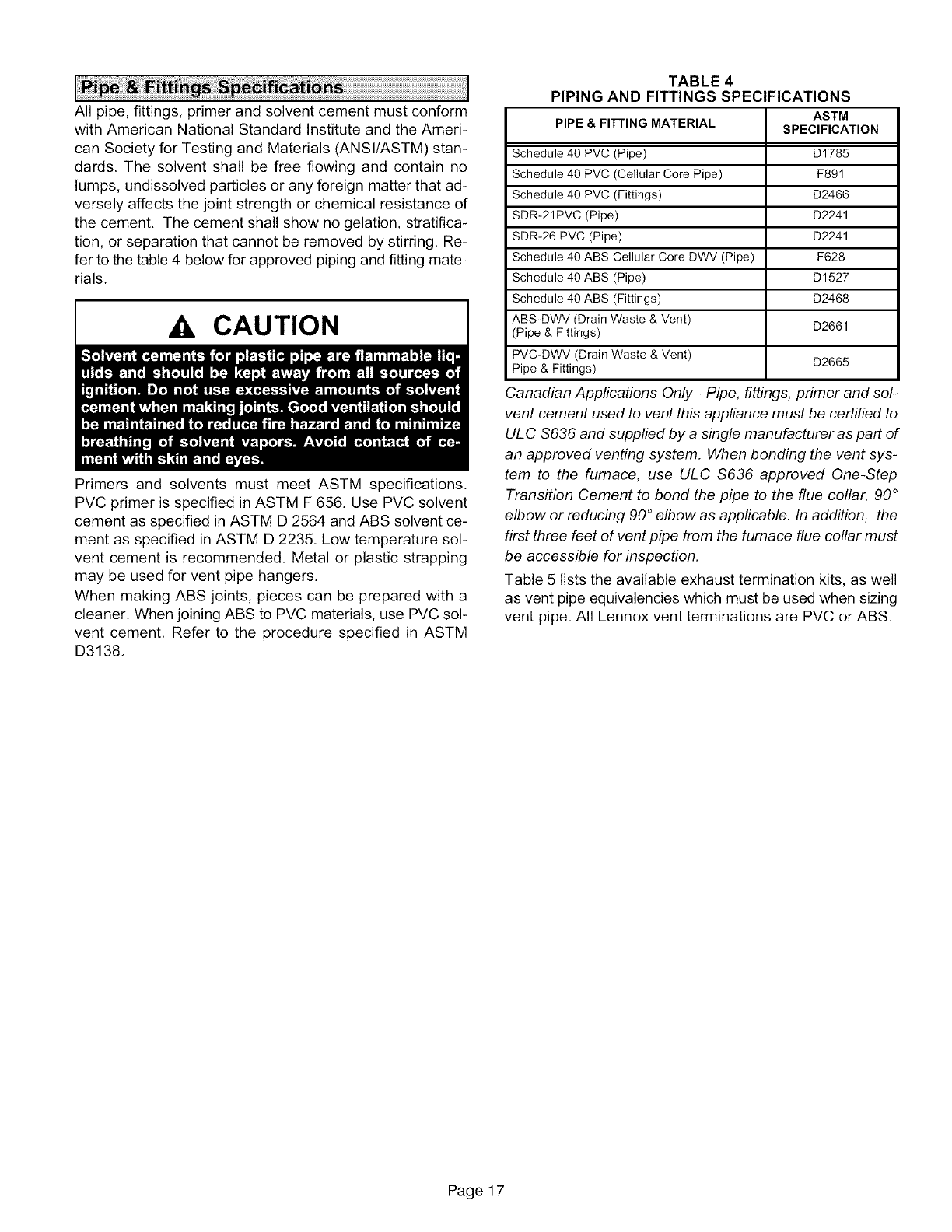
Allpipe,fittings,primerandsolventcementmustconform
withAmericanNationalStandardInstituteandtheAmeri-
canSocietyforTestingandMaterials(ANSI/ASTM)stan-
dards.Thesolventshallbefreeflowingandcontainno
lumps,undissolvedparticlesoranyforeignmatterthatad-
verselyaffectsthejointstrengthorchemicalresistanceof
thecement,Thecementshallshownogelation,stratifica-
tion,orseparationthatcannotberemovedbystirring,Re-
fertothetable4 belowforapprovedpipingandfittingmate-
rials.
,&, CAUTION
Primers and solvents must meet ASTM specifications.
PVC primer is specified in ASTM F 656. Use PVC solvent
cement as specified in ASTM D 2564 and ABS solvent ce-
ment as specified in ASTM D 2235. Low temperature sol-
vent cement is recommended. Metal or plastic strapping
may be used for vent pipe hangers.
When making ABS joints, pieces can be prepared with a
cleaner. When joining ABS to PVC materials, use PVC sol-
vent cement. Refer to the procedure specified in ASTM
D3138.
TABLE 4
PIPING AND FITTINGS SPECIFICATIONS
ASTM
PIPE & FITTING MATERIAL SPECIFICATION
Schedule 40 PVC (Pipe) D1785
Schedule 40 PVC (Cellular Core Pipe) F891
Schedule 40 PVC (Fittings) D2466
SDR-21PVC (Pipe) D2241
SDR-26 PVC (Pipe) D2241
Schedule 40 ABS Cellular Core DWV (Pipe) F628
Schedule 40 ABS (Pipe) D1527
Schedule 40 ABS (Fittings) D2468
ABS-DWV (Drain Waste & Vent) D2661
(Pipe & Fittings)
PVC-DWV (Drain Waste & Vent) D2665
Pipe & Fittings)
Canadian Applications Only - Pipe, fittings, primer and sol-
vent cement used to vent this appliance must be certified to
ULC $636 and supplied by a single manufacturer as part of
an approved venting system. When bonding the vent sys-
tem to the furnace, use ULC S636 approved One-Step
Transition Cement to bond the pipe to the flue collar, 90o
elbow or reducing 90 °elbow as applicable. In addition, the
first three feet of vent pipe from the furnace flue collar must
be accessible for inspection.
Table 5 lists the available exhaust termination kits, as well
as vent pipe equivalencies which must be used when sizing
vent pipe. All Lennox vent terminations are PVC or ABS.
Page 17
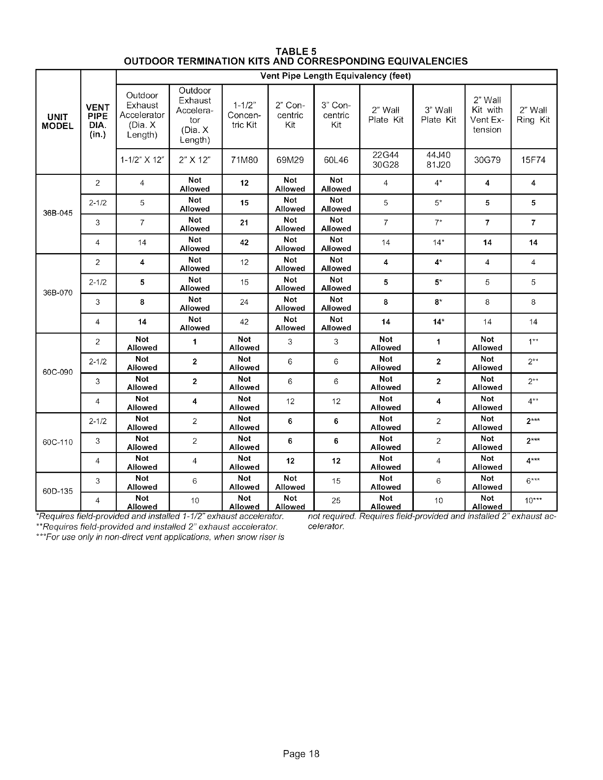
TABLE 5
OUTDOOR TERMINATION KITS AND CORRESPONDING EQUIVALENCIES
Outdoor
VENT Exhaust
UNIT PIPE Accelerator
MODEL DIA. (Dia. X
(in.) Length)
Outdoor
Exhaust
Accelera-
tor
(Dia. X
Length)
Vent Pipe Length Equivalency (feet)
1-1/2"
Concen-
tric Kit
2" Con-
centric
Kit
3" Con-
centric
Kit
2" Wall
Plate Kit
3" Wall
Plate Kit
2" Wall
Kit with
Vent Ex-
tension
2" Wall
Ring Kit
22G44 44J40
1-1/2" X 12" 2" X 12" 71M80 69M29 60L46 30G79 15F74
30G28 81J20
2 4 Not 12 Not Not 4 4* 4 4
Allowed Allowed Allowed
2-1/2 5 Not 15 Not Not 5 5* 5 5
Allowed Allowed Allowed
36B-045
3 7 Not 21 Not Not 7 7* 7 7
Allowed Allowed Allowed
4 14 Not 42 Not Not 14 14" 14 14
Allowed Allowed Allowed
2 4 Not 12 Not Not 4 4* 4 4
Allowed Allowed Allowed
2-1/2 5 Not 15 Not Not 5 5* 5 5
Allowed Allowed Allowed
36B-070
3 8 Not 24 Not Not 8 8* 8 8
Allowed Allowed Allowed
4 14 Not 42 Not Not 14 14" 14 14
Allowed Allowed Allowed
2 Not 1 Not 3 3 Not 1 Not 1"*
Allowed Allowed Allowed Allowed
2-1/2 Not 2Not 6 6 Not 2Not 2**
Allowed Allowed Allowed Allowed
60C-090
3 Not 2Not 6 6 Not 2Not 2**
Allowed Allowed Allowed Allowed
4 Not 4 Not 12 12 Not 4 Not 4**
Allowed Allowed Allowed Allowed
2-1/2 Not 2 Not 6 6 Not 2 Not 2***
Allowed Allowed Allowed Allowed
60C-110 3 Not 2 Not 6 6 Not 2 Not 2***
Allowed Allowed Allowed Allowed
4 Not 4 Not 12 12 Not 4 Not 4***
Allowed Allowed Allowed Allowed
3 Not 6 Not Not 15 Not 6 Not 6***
Allowed Allowed Allowed Allowed Allowed
60D-135
4 Not 10 Not Not 25 Not 10 Not 10"**
Allowed Allowed Allowed Allowed Allowed
not required. Requires field-provided and installed 2" exhaust ac-
celerator.
*Requires field-provided and installed 1-1/2" exhaust accelerator.
**Requires field-provided and instafled 2" exhaust accelerator.
***For use only in non-direct vent appfications, when snow riser is
Page 18
The G61MP can be installed as either a Non-Direct Vent
or a Direct Vent gas central furnace.
NOTE -In Non-Direct Vent installations, combustion air is
taken from indoors and flue gases are discharged out-
doors. In Direct Vent installations, combustion air is taken
from outdoors and flue gases are discharged outdoors.
Intake and exhaust pipe sizing in Direct Vent applications
and exhaust pipe sizing in Non-Direct Vent applications --
Size pipe according to tables 6 and 7. Table 6 lists the mini-
mum equivalent vent pipe lengths permitted. Table 7 lists
the maximum equivalent pipe lengths permitted.
Maximum vent length is defined as:
Total length (linear feet) of pipe,
Plus Equivalent length (feet) of fittings,
Plus Equivalent length (feet) of termination.
NOTE -Include ALL pipe and ALL fittings, both in
doors and outdoors.
Regardless of the diameter of pipe used, the standard roof
and wall terminations described in section Exhaust Piping
Terminations should be used. Exhaust vent termination
pipe is sized to optimize the velocity of the exhaust gas as it
exits the termination. Refer to table 8.
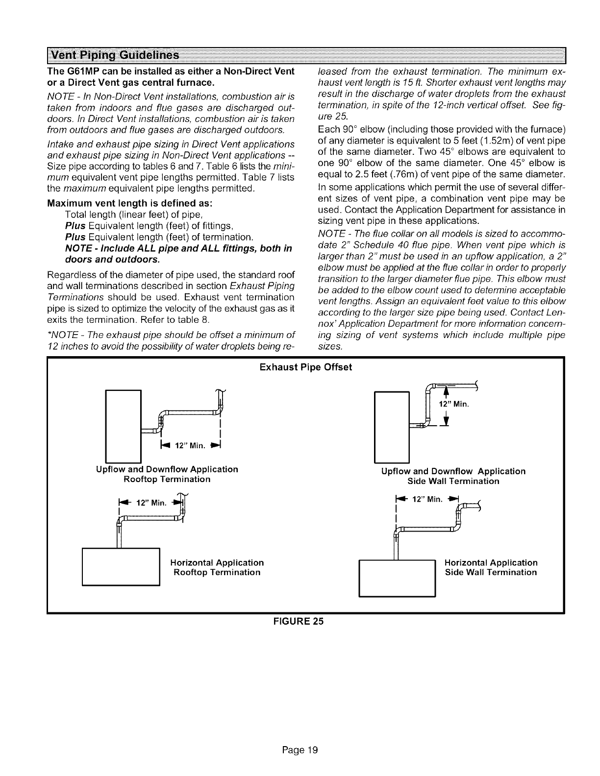
*NOTE- The exhaust pipe should be offset a minimum of
12 inches to avoid the possibility of water droplets being re-
Exhaust
I
I
12" Min..1_
m
_flow and Downflow Application
Rooftop Termination
12" Min. -_
I,#
Horizontal Application
Rooftop Termination
leased from the exhaust termination. The minimum ex-
haust vent length is 15 ft. Shorter exhaust vent lengths may
result in the discharge of water droplets from the exhaust
termination, in spite of the 12-inch vertical offset. See fig-
ure 25.
Each 90° elbow (including those provided with the furnace)
of any diameter is equivalent to 5 feet (1.52m) of vent pipe
of the same diameter. Two 45° elbows are equivalent to
one 90° elbow of the same diameter. One 45° elbow is
equal to 2.5 feet (.76m) of vent pipe of the same diameter.
In some applications which permit the use of several differ-
ent sizes of vent pipe, a combination vent pipe may be
used. Contact the Application Department for assistance in
sizing vent pipe in these applications.
NOTE -The flue collar on all models is sized to accommo-
date 2" Schedule 40 flue pipe. When vent pipe which is
larger than 2" must be used in an upflow application, a 2"
elbow must be applied at the flue collar in order to properly
transition to the larger diameter flue pipe. This elbow must
be added to the elbow count used to determine acceptable
vent lengths. Assign an equivalent feet value to this elbow
according to the larger size pipe being used. Contact Len-
nox' Application Department for more information concern-
ing sizing of vent systems which include multiple pipe
sizes.
Pipe Offset
I
-F
Upflow and Downflow Application
Side Wall Termination
12" ain. "P_
,
I
II II
Horizontal Application
Side Wall Termination
FIGURE 25
Page 19
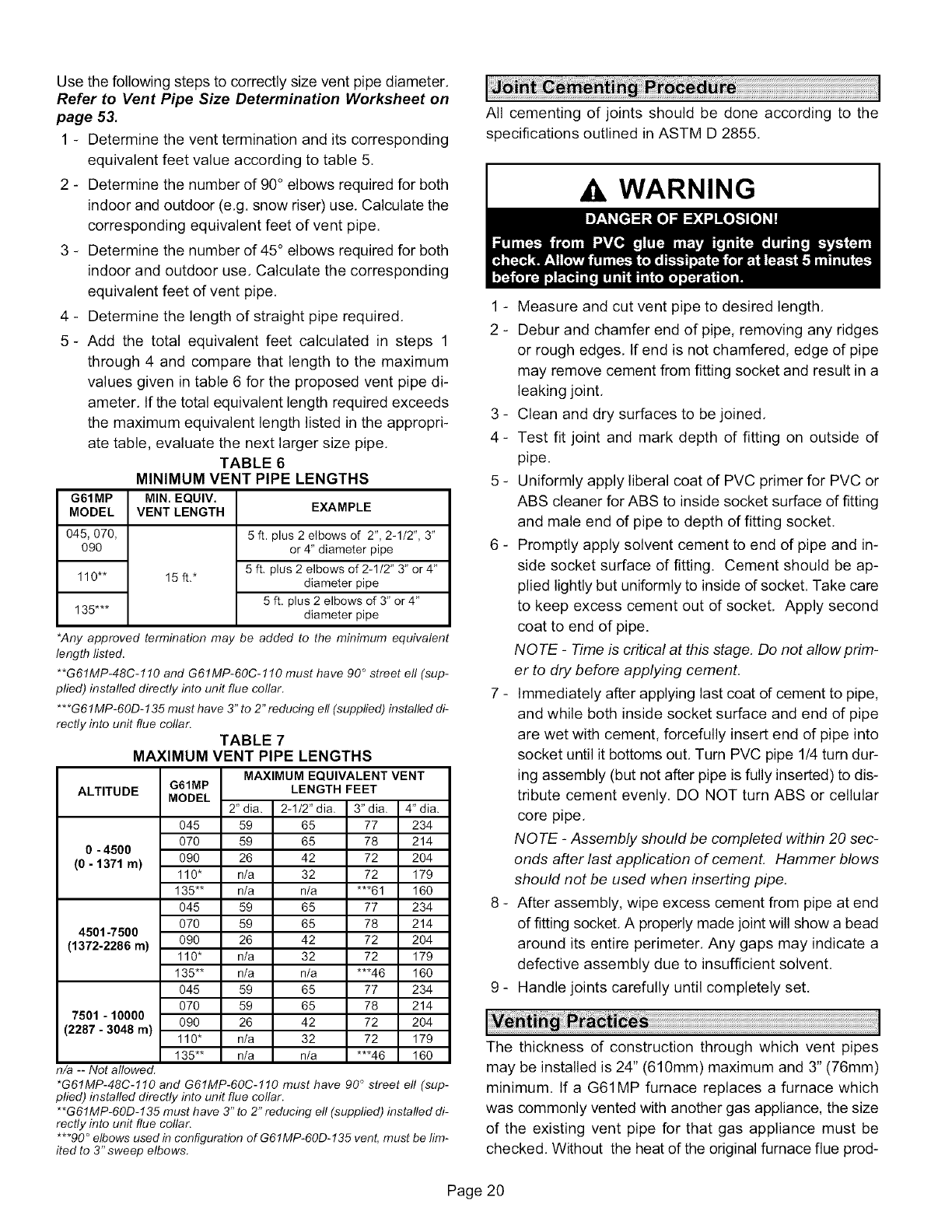
Usethefollowingstepstocorrectlysizeventpipediameter,
Refer to Vent Pipe Size Determination Worksheet on
page 53.
1 - Determine the vent termination and its corresponding
equivalent feet value according to table 5.
2 - Determine the number of 90° elbows required for both
indoor and outdoor (e,g. snow riser) use, Calculate the
corresponding equivalent feet of vent pipe.
3 - Determine the number of 45° elbows required for both
indoor and outdoor use, Calculate the corresponding
equivalent feet of vent pipe,
4 - Determine the length of straight pipe required,
5- Add the total equivalent feet calculated in steps 1
through 4 and compare that length to the maximum
values given in table 6 for the proposed vent pipe di-
ameter, If the total equivalent length required exceeds
the maximum equivalent length listed in the appropri-
ate table, evaluate the next larger size pipe,
TABLE 6
MINIMUM VENT PIPE LENGTHS
G61MP
MODEL
045,070,
09O
110"*
MIN. EQUIV.
VENT LENGTH
15 ft.*
135"**
*Any approved termination ma
length listed.
EXAMPLE
5 ft. plus 2 elbows of 2", 2-1/2", 3"
or 4" diameter pipe
5 ft, plus 2 elbows of 2-1/2" 3" or 4"
diameter pipe
5 ft. plus 2 elbows of 3" or 4"
diameter pipe
' be added to the minimum equivalent
**G61MP-48C-110 and G61MP-60C-110 must have 90 °street ell (sup-
plied) installed directly into unit flue collar.
***G61MP-60D-135 must have 3" to 2" reducing ell (supplied) installed di-
rectly into unit flue collar. TABLE 7
MAXIMUM VENT PIPE LENGTHS
G61MP
ALTITUDE MODEL
MAXIMUM EQUIVALENT VENT
LENGTH FEET
2" dia. 2-1/2" dia. 3" dia. 4" dia.
045 59 65 77 234
070 59 65 78 214
0 - 4500
(0 - 1371 m) 090 26 42 72 204
110* n/a 32 72 179
135"* n/a n/a **'61 160
045 59 65 77 234
070 59 65 78 214
4501-7500
(1372-2286 m) 090 26 42 72 204
110* n/a 32 72 179
135** n/a n/a ***46 160
045 59 65 77 234
070 59 65 78 214
7501 - 10000 090 26 42 72 204
(2287 - 3048 m) 110* n/a 32 72 179
135** n/a n/a ***46 160
n/a -- Not allowed.
*G61MP-48C-110 and G61MP-60C-110 must have 90 ° street ell (sup-
plied) installed directly into unit flue collar.
**G61MP-60D-135 must have 3" to 2" reducing ell (supplied) installed di-
rectly into unit flue collar.
***90 ° elbows used in configuration of G61MP-60D-135 vent, must be lim-
ited to 3"sweep elbows.
All cementing of joints should be done according to the
specifications outlined in ASTM D 2855,
WARNING
1 - Measure and cut vent pipe to desired length,
2 - Debur and chamfer end of pipe, removing any ridges
or rough edges, If end is not chamfered, edge of pipe
may remove cement from fitting socket and result in a
leaking joint,
3 - Clean and dry surfaces to be joined,
4- Test fit joint and mark depth of fitting on outside of
pipe.
5 - Uniformly apply liberal coat of PVC primer for PVC or
ABS cleaner for ABS to inside socket surface of fitting
and male end of pipe to depth of fitting socket.
6 - Promptly apply solvent cement to end of pipe and in-
side socket surface of fitting. Cement should be ap-
plied lightly but uniformly to inside of socket. Take care
to keep excess cement out of socket, Apply second
coat to end of pipe.
NQ TE -Time is critical at this stage. Do not allow prim-
er to dry before applying cement.
7 - Immediately after applying last coat of cement to pipe,
and while both inside socket surface and end of pipe
are wet with cement, forcefully insert end of pipe into
socket until it bottoms out, Turn PVC pipe 1/4 turn dur-
ing assembly (but not after pipe is fully inserted) to dis-
tribute cement evenly, DO NOT turn ABS or cellular
core pipe,
NOTE -Assembly should be completed within 20 sec-
onds after last application of cement. Hammer blows
should not be used when inserting pipe.
8 - After assembly, wipe excess cement from pipe at end
of fitting socket, A properly made joint will show a bead
around its entire perimeter, Any gaps may indicate a
defective assembly due to insufficient solvent,
9 - Handle joints carefully until completely set,
The thickness of construction through which vent pipes
may be installed is 24" (610mm) maximum and 3" (76mm)
minimum. If a G61MP furnace replaces a furnace which
was commonly vented with another gas appliance, the size
of the existing vent pipe for that gas appliance must be
checked, Without the heat of the original furnace flue prod-
Page 20
ucts,theexistingventpipeis probablyoversizedforthe
singlewaterheaterorotherappliance.Theventshouldbe
checkedforproperdrawwiththeremainingappliance.
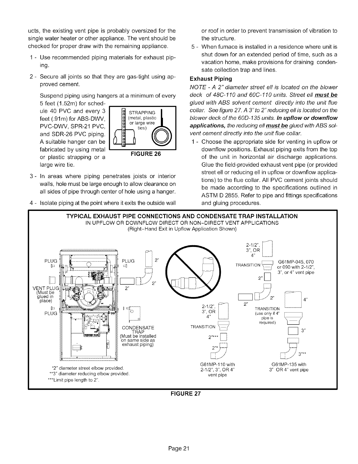
1- Userecommendedpipingmaterialsforexhaustpip-
ing.
2 - Securealljointssothattheyaregas-tightusingap-
provedcement,
Suspendpipingusinghangersata minimumofevery
5feet(1.52m)forsched-
ule40 PVCandevery3
feet(.91m)forABS-DWV,
PVC-DWV,SPR-21PVC,
andSDR-26PVCpiping.
A suitablehangercanbe
fabricatedbyusingmetal
or plasticstrappingor a
largewiretie.
STRAPPING I
(metal, plastic II
or large wire J[
ties) 0
FIGURE 26
3- In areas where piping penetrates joists or interior
walls, hole must be large enough to allow clearance on
all sides of pipe through center of hole using a hanger.
4 - Isolate piping at the point where it exits the outside wall
or roof in order to prevent transmission of vibration to
the structure.
5 - When furnace is installed in a residence where unit is
shut down for an extended period of time, such as a
vacation home, make provisions for draining conden-
sate collection trap and lines.
Exhaust Piping
NOTE -A2" diameter street ell is located on the blower
deck of 48C-110 and 60C-f10 units. Street ell must be
glued with ABS solvent cement directly into the unit flue
collar. See figure 27. A 3"to 2"reducing ellis Iocated on the
blower deck of the 60D-135 units. In upflow or downflow
applications, the reducing ell must be glued with ABS sol-
vent cement directly into the unit flue collar.
1 - Choose the appropriate side for venting in upflow or
downflow positions. Exhaust piping exits from the top
of the unit in horizontal air discharge applications.
Glue the field-provided exhaust vent pipe (or provided
street ell or reducing ell in upflow or downflow applica-
tions) to the flue collar. All PVC cement joints should
be made according to the specifications outlined in
ASTM D 2855. Refer to pipe and fittings specifications
and gluing procedures.
TYPICAL EXHAUST PIPE CONNECTIONS AND CONDENSATE TRAP INSTALLATION
IN UPFLOW OR DOWNFLOW DIRECT OR NON-DIRECT VENT APPLICATIONS
(Right-Hand Exit in Upflow Application Shown)
PLUG
VENT PLUC
(Must be
glued in
place)
PLUG
2"
I _ 2-1/2",
3", OR
4"
CONDENSATE TRANSiTiON
TRAP
Must be installed 2 ..... [_
on same side as L_
exhaust piping)
2-1/2",
3", OR
4"
G61MP-045,070TRANSmON or 090 with 2-1/2",
3", or 4" vent pipe
II
2"
4"
2"
TRANSmON
(use only if 4"
pipe is
required)
13"
*2" diameter street elbow provided,
**3" diameter reducing elbow provided.
***Limit pipe length to 2".
G61MP-110 with
2-1/2", 3", OR 4"
vent pipe
FIGURE 27
G61MP-135 with
3" OR 4" vent pipe
Page 21
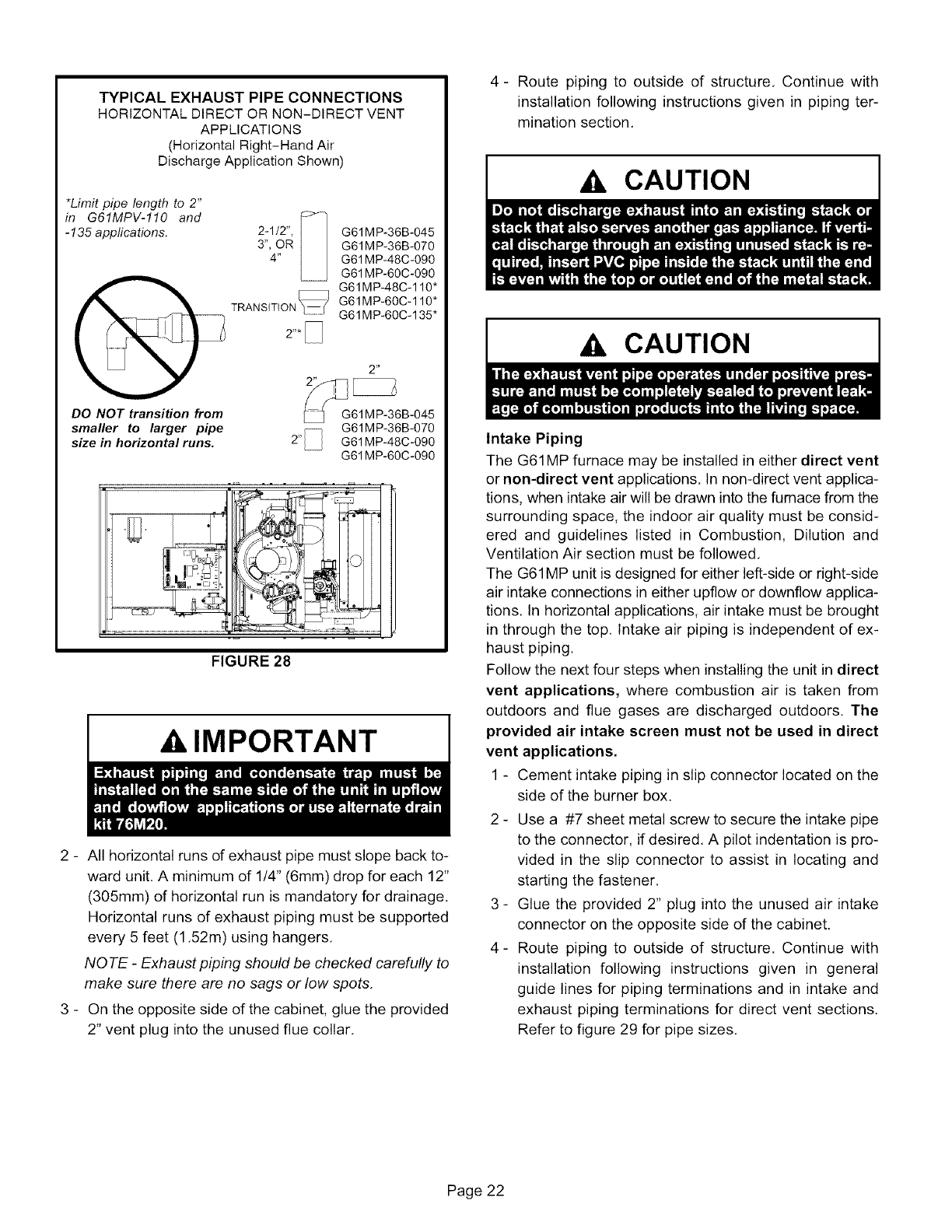
TYPICAL EXHAUST PIPE CONNECTIONS
HORIZONTAL DIRECT OR NON-DIRECT VENT
APPLICATIONS
(Horizontal Right-Hand Air
Discharge Application Shown)
*Limit pipe length to 2"
in G61MPV-110 and
-135 applications.
2-1/2", _>_i G61MP-36B-045
3", OR G61MP-36B-070
4" G61 MP-48C-090
G61MP-60C-090
G61MP-48C-110"
TRANSITION_ G61MP-60C-110"
G61MP-60C-135*
2"*
DO NOT transition from
smaller to larger pipe
size in horizontal runs.
G61MP-36B-045
G61MP-36B-070
G61 MP-48C-090
G61MP-60C-090
.J
FIGURE 28
A, IMPORTANT
2 - All horizontal runs of exhaust pipe must slope back to-
ward unit. A minimum of 1/4" (6mm) drop for each 12"
(305mm) of horizontal run is mandatory for drainage.
Horizontal runs of exhaust piping must be supported
every 5 feet (1,52m) using hangers,
NOTE -Exhaust piping should be checked carefully to
make sure there are no sags or low spots,
3 - On the opposite side of the cabinet, glue the provided
2" vent plug into the unused flue collar.
4- Route piping to outside of structure, Continue with
installation following instructions given in piping ter-
mination section.
Ak CAUTION
,& CAUTION
Intake Piping
The G61MP furnace may be installed in either direct vent
or non-direct vent applications. In non-direct vent applica-
tions, when intake air will be drawn into the furnace from the
surrounding space, the indoor air quality must be consid-
ered and guidelines listed in Combustion, Dilution and
Ventilation Air section must be followed,
The G61MP unit is designed for either left-side or right-side
air intake connections in either upflow or downflow applica-
tions. In horizontal applications, air intake must be brought
in through the top. Intake air piping is independent of ex-
haust piping.
Follow the next four steps when installing the unit in direct
vent applications, where combustion air is taken from
outdoors and flue gases are discharged outdoors. The
provided air intake screen must not be used in direct
vent applications.
1 - Cement intake piping in slip connector located on the
side of the burner box.
2 - Use a #7 sheet metal screw to secure the intake pipe
to the connector, if desired, A pilot indentation is pro-
vided in the slip connector to assist in locating and
starting the fastener,
3 - Glue the provided 2" plug into the unused air intake
connector on the opposite side of the cabinet.
4- Route piping to outside of structure. Continue with
installation following instructions given in general
guide lines for piping terminations and in intake and
exhaust piping terminations for direct vent sections.
Refer to figure 29 for pipe sizes.
Page 22
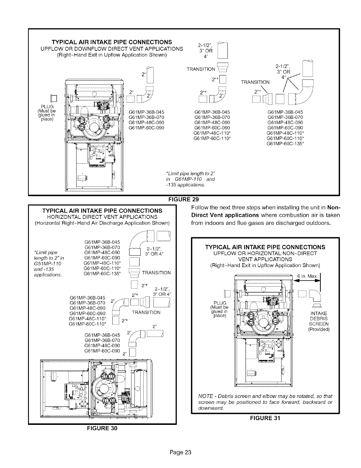
TYPICAL AIR INTAKE PIPE CONNECTIONS
UPFLOW OR DOWNFLOW DIRECT VENT APPLICATIONS
(Right-Hand Exit in Upfiow Application Shown) 2-1/2",
3" OR
4"
PLUG
(Must be
glued in
place)
I "q
G61MP-36B-045
G61MP-36B-070
G61 MP-48C-090
G61MP-60C-090
TRANSITION
2"* [_
2"* F/_
G61MP-36B-045
G61MP-36B-070
G61 MP-48C-090
G61MP-60C-090
G61MP-48C-110"
G61MP-60C-110"
*Limit pipe length to 2"
in G61MP-110 and
-135 applications.
TRANSITION
G61MP-36B-045
G61MP-36B-070
G61 MP-48C-090
G61MP-60C-090
G61MP-48C-110"
G61MP-60C-110"
G61MP-60C-135*
FIGURE 29
Follow the next three steps when installing the unit in Non-
TYPICAL AIR INTAKE PIPE CONNECTIONS
HORIZONTAL DIRECT VENT APPLICATIONS
(Horizontal Right-Hand Air Discharge Application Shown)
G61MP-36B-045
G61MP-36B-070
*Limit pipe G61 MP-48C-090
length to 2" in G61M P-60C-090
G51MP-110 G61MP-48C-110"
and -135 G61MP-60C-110"
applications. G61 MP-60C-135*
= ,
.............r_ ...................................................................
_ TRANSITION
2"* 2-1/2",
2"* 3" OR 4"
G61MP-36B-045 _ _
G61MP-36B-070
G61 MP-48C-090
G61MP-60C-090 TRANSITION
G61MP-48C-110* _ 2"*
G61MP-60C-110" 2"
G61MP-36B-04
G61MP-36B-070
G61 MP-48C-690
G61MP-60C-090 2" _
Direct Vent applications where combustion air is taken
from indoors and flue gases are discharged outdoors.
TYPICAL AIR INTAKE PIPE CONNECTIONS
UPFLOW OR HORIZONTAL NON-DIRECT
VENT APPLICATIONS
(Right-Hand Exit in Upf!ow Application Shown)
PLUG
(Must be
glued in
place) INTAKE
DEBRIS
SCREEN
(Provided)
NOTE -Debris screen and elbow may be rotated, so that
screen may be positioned to face forward, backward or
downward.
FIGURE 31
FIGURE 30
Page 23
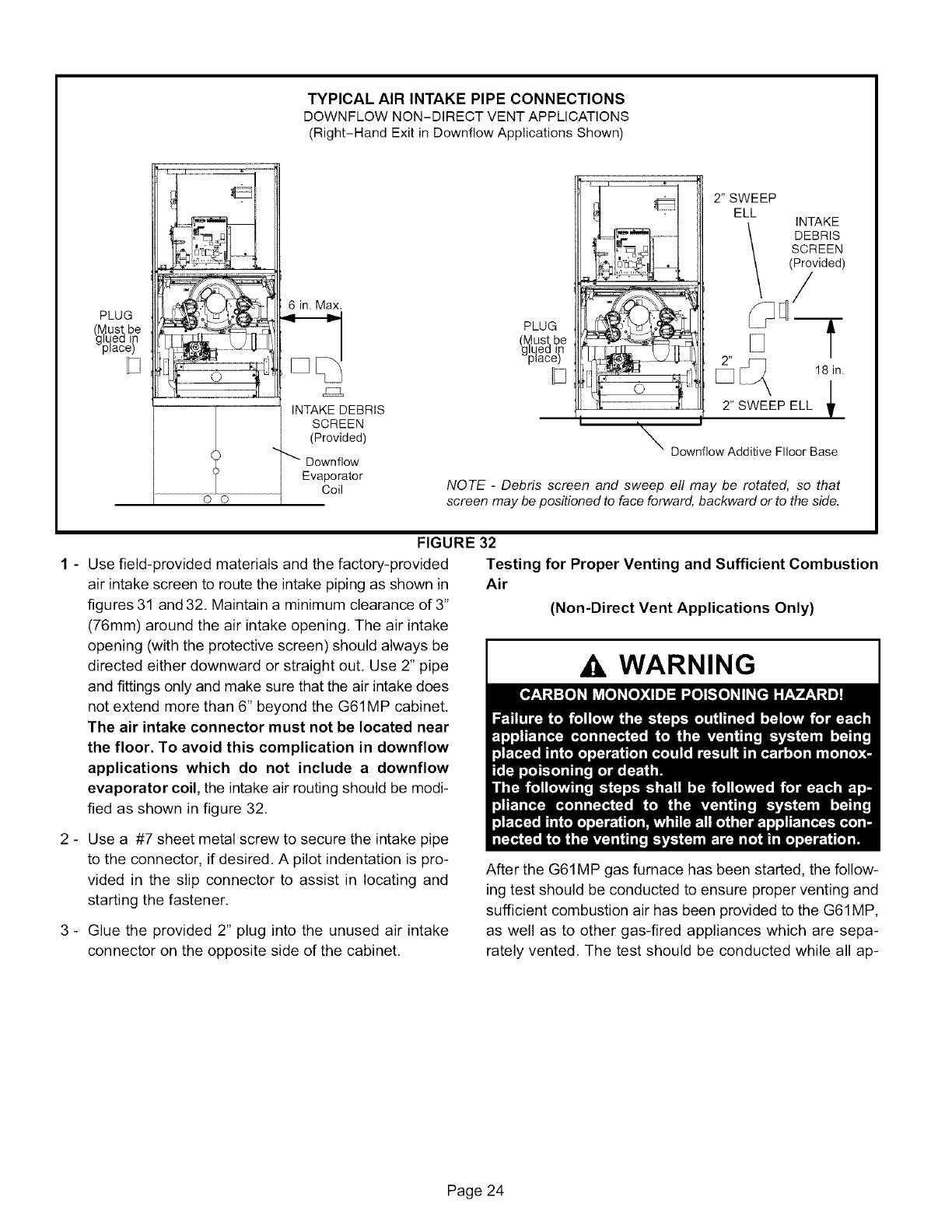
TYPICAL AIR INTAKE PIPE CONNECTIONS
DOWNFLOW NON-DIRECT VENT APPLICATIONS
(Right-Hand Exit in Downflow Applications Shown)
PLUG
_lpqUst, be
ea in
lace)
0 0
6 in. Max,
r_
INTAKE DEBRIS
SCREEN
(Provided)
Downflow
Evaporator
Coil
PLUG
(g_ust,be
ea I
_L_ace_
I
I
2" SWEEP
ELL INTAKE
DEBRIS
SCREEN
(Provided)
/f
[_ 181n.|
2" SWEEP ELL
T
i
_\ Downflow Additive FIIoor Base
NOTE -Debris screen and sweep ell may be rotated, so that
screen may be positioned to face forward, backward or to the side.
FIGURE 32
1 - Use field-provided materials and the factory-provided
air intake screen to route the intake piping as shown in
figures 31 and 32, Maintain a minimum clearance of 3"
(76mm) around the air intake opening. The air intake
opening (with the protective screen) should always be
directed either downward or straight out, Use 2" pipe
and fittings only and make sure that the air intake does
not extend more than 6" beyond the G61MP cabinet,
The air intake connector must not be located near
the floor. To avoid this complication in downflow
applications which do not include a downflow
evaporator coil, the intake air routing should be modi-
fied as shown in figure 32,
Testing for Proper Venting and Sufficient Combustion
Air
(Non-Direct Vent Applications Only)
WARNING
2 - Use a #7 sheet metal screw to secure the intake pipe
to the connector, if desired, A pilot indentation is pro-
vided in the slip connector to assist in locating and
starting the fastener,
3 - Glue the provided 2" plug into the unused air intake
connector on the opposite side of the cabinet,
After the G61MP gas furnace has been started, the follow-
ing test should be conducted to ensure proper venting and
sufficient combustion air has been provided to the G61MP,
as well as to other gas-fired appliances which are sepa-
rately vented. The test should be conducted while all ap-
Page 24
pliances(bothinoperationandthosenotinoperation)are
connectedtotheventingsystembeingtested.Ifthevent-
ingsystemhasbeeninstalledimproperly,orif provisions
havenotbeenmadeforsufficientamountsofcombustion
air,correctionsmustbemadeasoutlinedintheprevious
section.
1- Sealanyunusedopeningsintheventingsystem.
2 - Visuallyinspecttheventingsystemforpropersizeand
horizontalpitch.Determinethereisnoblockageorre-
striction,leakage,corrosion,or otherdeficiencies
whichcouldcauseanunsafecondition.
3- Totheextentthatitispractical,closeallbuildingdoors
andwindowsandall doorsbetweenthe spacein
whichtheappliancesconnectedtotheventingsystem
arelocatedandotherspacesof thebuilding.
4 - Closefireplacedampers.
5- Turnon clothesdryersandanyappliancesnotcon-
nectedto theventingsystem.Turnonanyexhaust
fans,suchasrangehoodsandbathroomexhausts,so
theywilloperateatmaximumspeed.Donotoperatea
summerexhaustfan.
6 - Followthelightinginstructionto placetheappliance
beinginspectedintooperation.Adjustthermostatso
appliancewilloperatecontinuously.
7- Usetheflameofmatchorcandletotestforspillageof
fluegasesatthedrafthoodreliefopeningafter5min-
utesof mainburneroperation.
8- If improperventingis observedduringany of the
abovetests,theventingsystemmustbecorrectedor
sufficientcombustion/make-upairmustbeprovided.
Theventingsystemshouldbere-sizedto approach
theminimumsizeas determinedby usingtheap-
propriatetablesinappendixGinthecurrentstandards
oftheNationalFuelGasCodeANSFZ223.1/NPFA54
inthe U.S.A.,andtheappropriateNaturalGasand
Propaneappliancesventingsizingtablesinthecur-
rentstandardoftheCSA-B149NaturalGasandPro-
paneInstallationCodesinCanada.
9- Afterdeterminingthateachapplianceremainingcon-
nectedto thecommonventingsystemproperlyvents
whentestedasindicatedinstep3,returndoors,win-
dows,exhaustfans,fireplacedampersandanyother
gas-burningapplianceto theirpreviousconditionof
use.
General Guidelines for Vent Terminations for Non-Di-
rect Vent Installations.
In Non-Direct Vent applications, combustion air is taken
from indoors and the flue gases are discharged to the out-
doors. The G61MP is then classified as a non-direct vent,
Category IV gas furnace. In Non-Direct Vent applications,
the vent termination is limited by local building codes, In the
absence of local codes, refer to the current National Fuel
Gas Code ANSI Z223-1/NFPA 54 in U.S.A., and current
CSA-B149 Natural Gas and Propane Installation Codes in
Canada for details.
Position termination end according to location given in fig-
ure 33. In addition, position termination end so it is free
from any obstructions and above the level of snow accu-
mulation (where applicable). The termination should be at
least 12 inches (305mm) from any opening through which
flue products could enter the building.
At vent termination, care must be taken to maintain
protective coatings over building materials (prolonged
exposure to exhaust condensate can destroy protective
coatings). It is recommended that the exhaust outlet not be
located within 6 feet (1.8m) of a condensing unit because
the condensate can damage the painted coating.
NOTE -If winter design temperature is below 32°F (O°C),
exhaust piping should be insulated with 1/2" (f3mm), Ar-
maflex or equivalent when run through unheated space.
Do not leave any surface area of exhaust pipe open to out-
side air; exterior exhaust pipe should be insulated with 1/2"
(13mm) Armaflex or equivalent. In extreme cold climate
areas, 3/4" (19mm) Armaflex or equivalent may be neces-
sary. Insulation on outside runs of exhaust pipe must be
painted or wrapped to protect insulation from deterioration.
Exhaust pipe insulation may not be necessary in some
specific applications.
NOTE -During extremely cold temperatures, below
approximately 20°F (6. 7°C), units with long runs of vent
pipe through unconditioned space, even when insulated,
may form ice in the exhaust termination that prevents the
unit from operating properly. Longer run times of at least 5
minutes will alleviate most icing problems. Also, a heating
cable may be installed on exhaust piping and termination to
prevent freeze-ups. Heating cable installation kit is avail-
able from Lennox. See Condensate Piping section for part
numbers.
AIMPORTANT
,&IMPORTANT
Page 25
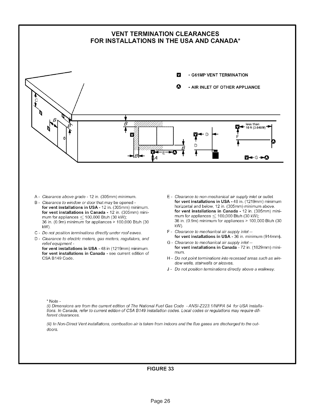
VENT TERMINATION CLEARANCES
FOR INSTALLATIONS IN THE USA AND CANADA*
[] - G61MP VENT TERMINATION
O - AIR INLET OF OTHER APPLIANCE
D!
A - Clearance above grade - 12 in. (305mm) minimum.
B - Clearance to window or door that may be opened -
for vent installations in USA- 12 in (305mm) minimum.
for vent installations in Canada - 12 in. (305mm) mini-
mum for appliances _ 100,000 Btuh (30 kW);
36 in. (09m) minimum for appliances > 100,000 Btuh (30
kW)
C - Do not position terminations directly under roof eaves.
D - Clearance to electric meters, gas meters, regulators, and
refief equipment -
for vent installations in USA -48 in (1219mm) minimum.
for vent installations in Canada - see current edition of
CSA B149 Code
E - Clearance to non-mechanical air supply inlet or outlet
for vent installations in USA -48 in (1219mm) minimum
horizontal and below, 12 in. (305mm) minimum above
for vent installations in Canada - 12 in. (305mm) mini-
mum for appliances _ 100,000 Btuh (30 kW);
36 in. (09m) minimum for appliances > 100,000 Btuh (30
kW).
F - Clearance to mechanical air supply inlet --
for vent installations in USA - 36 in. minimum (914mm).
G - Clearance to mechanical air supply inlet --
for vent installations in Canada - 72 in. (1829mm) mini-
mum
H - Do notpoint terminations into recessed areas such as win-
dow wells, stairwells or alcoves.
J - Do notposition terminations directly above a walkway.
* Note -
(I) Dimensions are from the current edition of The National Fuel Gas Code - ANSI-Z223.1/NFPA 54 for USA installa-
tions. In Canada, refer to current edition of CSA B149 installation codes. Local codes or regulations may require dif-
ferent clearances.
(11)In Non-Direct Vent installations, combustion air is taken from indoors and the flue gases are discharged to the out-
doors.
FIGURE 33
Page 26
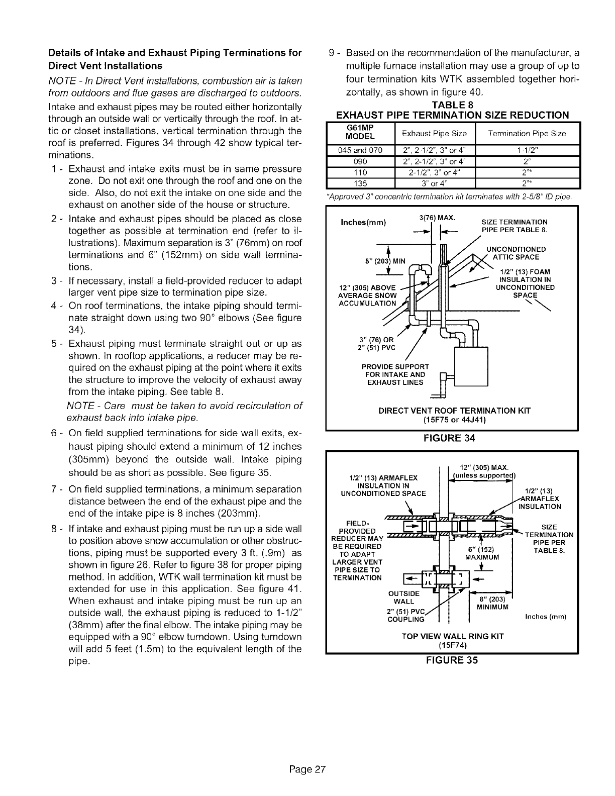
Details of Intake and Exhaust Piping Terminations for
Direct Vent Installations
NOTE -In Direct Vent installations, combustion air is taken
from outdoors and flue gases are discharged to outdoors,
Intake and exhaust pipes may be routed either horizontally
through an outside wall or vertically through the roof. In at-
tic or closet installations, vertical termination through the
roof is preferred, Figures 34 through 42 show typical ter-
minations.
1 - Exhaust and intake exits must be in same pressure
zone, Do not exit one through the roof and one on the
side. Also, do not exit the intake on one side and the
exhaust on another side of the house or structure.
2 - Intake and exhaust pipes should be placed as close
together as possible at termination end (refer to il-
lustrations). Maximum separation is 3" (76mm) on roof
terminations and 6" (152mm) on side wall termina-
tions.
3 - If necessary, install a field-provided reducer to adapt
larger vent pipe size to termination pipe size.
4 - On roof terminations, the intake piping should termi-
nate straight down using two 90° elbows (See figure
34),
5 - Exhaust piping must terminate straight out or up as
shown, In rooftop applications, a reducer may be re-
quired on the exhaust piping at the point where it exits
the structure to improve the velocity of exhaust away
from the intake piping, See table 8.
NOTE -Care must be taken to avoid recirculation of
exhaust back into intake pipe,
6 - On field supplied terminations for side wall exits, ex-
haust piping should extend a minimum of 12 inches
(305mm) beyond the outside wall. Intake piping
should be as short as possible, See figure 35,
7 - On field supplied terminations, a minimum separation
distance between the end of the exhaust pipe and the
end of the intake pipe is 8 inches (203mm),
8 - If intake and exhaust piping must be run up a side wall
to position above snow accumulation or other obstruc-
tions, piping must be supported every 3 ft. (.9m) as
shown in figure 26. Refer to figure 38 for proper piping
method. In addition, WTK wall termination kit must be
extended for use in this application. See figure 41.
When exhaust and intake piping must be run up an
outside wall, the exhaust piping is reduced to 1-1/2"
(38mm) after the final elbow, The intake piping may be
equipped with a 90° elbow turndown. Using turndown
will add 5 feet (1.5m) to the equivalent length of the
pipe.
9 - Based on the recommendation of the manufacturer, a
multiple furnace installation may use a group of up to
four termination kits WTK assembled together hori-
zontally, as shown in figure 40,
TABLE 8
EXHAUST PIPE TERMINATION SIZE REDUCTION
G61MP
MODEL Exhaust Pipe Size Termination Pipe Size
045 and 070 2", 2-1/2", 3" or 4" 1-1/2"
090 2", 2-1/2", 3" or4" 2"
110 2-1/2", 3" or4" 2"*
135 3" or 4" 2"*
*Approved 3" concentric temfination kit temfinates with 2-5/8" ID pipe.
Inches(ram) 3(76) MAX. SIZE TERMINATION
_PIPE PER TABLE 8.
//
il I _ /UNCONDITIONED
6,,(2o M,N IJIII//P: ATT,CSPACE
_._t_ C:?q3IHF/"v'- "- 1,2,,(13)FOAM
I I_,-L/It Ir./ INSULATION IN
12" (305) ABOVE _1"[_,_/"/11 II'm- UNCONDITIONED
AVERAGE SNOW ,,_ I_'/ It II SPACE
AOOOMO T
3" (76) OR /_I I
2"(51)PVC /
PROVIDE SUPPORT II
FOR INTAKE AND [-_ I
EXHAUST LINES ___ I I
DIRECT VENT ROOF TERMINATION KIT
(15F75 or 44J41)
FIGURE 34
1/2" (13) ARMAFLEX
INSULATION IN
UNCONDITIONED SPACE
\
FIELD- /_
PROVIDED
REDUCER MAY
BE REQUIRED
TO ADAPT
LARGER VENT
PIPE SIZE TO
TERMINATION
OUT
WALL
2" (51) PVC/
COUPLING
/
12" (305) MAX.
_unless supportel)
| 1/2" (13)
_L/'ARMAFLEX
,_/ INSULATION
SIZE
•"_ TERMINATION
=3 PIPE PER
6" (152) TABLE 8
MAXIMUM
MINIMUM Inches (mm)
TOP VIEW WALL RING KIT
(15F74)
FIGURE 35
Page 27
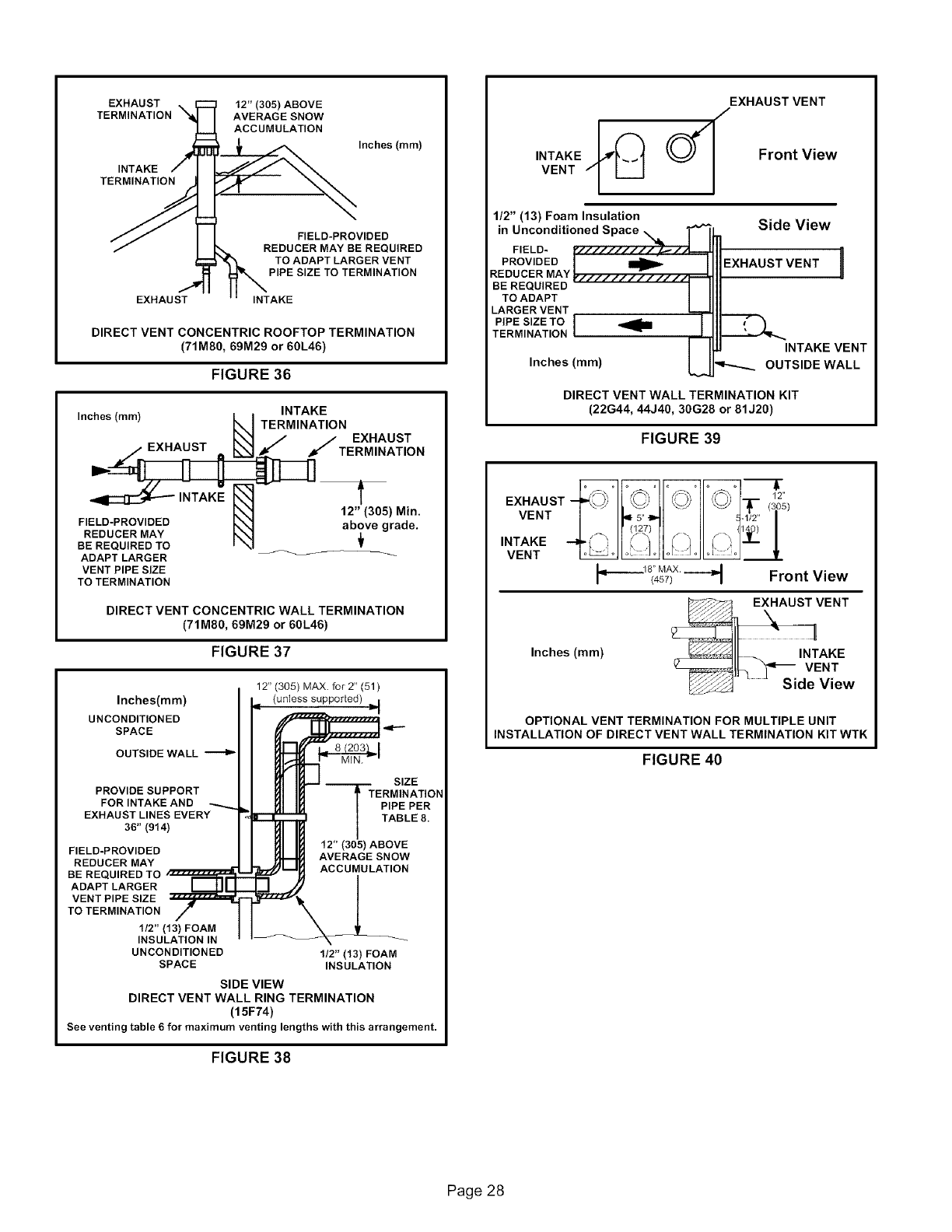
EXHAUST 12" (305) ABOVE
TERMINATION AVERAGE SNOW
ACCUMULATION
INTAKE
TERMINATION
Inches (mm)
FIELD-PROVIDED
REDUCER MAY BE REQUIRED
TO ADAPT LARGER VENT
PiPE SIZE TO TERMINATION
EXHAUST INTAKE
DIRECT VENT CONCENTRIC ROOFTOP TERMINATION
(71M80, 69M29 or 60L46)
FIGURE 36
Inches (mm)
EXHAUST
INTAKE
TERMINATION
EXHAUST
TERMINATION
FIELD-PROVIDED
REDUCER MAY
BE REQUIRED TO
ADAPT LARGER
VENT PIPE SIZE
TO TERMINATION
INTAKE
12" (305) Min.
above grade.
DIRECT VENT CONCENTRIC WALL TERMINATION
(71M80, 69M29 or 60L46)
FIGURE 37
Inches(mm)
UNCONDITIONED
SPACE
12" (305) MAX. for 2" (51)
(untess supported)
OUTSIDE WALL
SIZE
PROVIDE SUPPORT TERMINATION
FOR INTAKE AND PIPE PER
EXHAUST LINES EVERY TABLE 8.
36" (914)
FIELD-PROVIDED 12" (305) ABOVE
AVERAGE SNOW
REDUCER MAY ACCUMULATION
BE REQUIRED TO
ADAPT LARGER
VENT PIPE SIZE
TO TERMINATION
1/2" (13) FOAM
INSULATION IN
UNCONDITIONED 1/2" (13) FOAM
SPACE INSULATION
SIDE VIEW
DIRECT VENT WALL RING TERMINATION
(15F74)
See venting table 6 for maximum venting lengths with this arrangement.
FIGURE 38
EXHAUST VENT
/
INTAKE__ _VENT Front View
1/2" (13) Foam Insulation
in Space Side ViewUnconditioned
PROVIDEDFIELD- I,
EXHAUST VENT
REDUCER MAY
BE REQUIRED
TO ADAPT
LARGER VENT
PIPE SlZETO /
TERMINATION INTAKE VENT
Inches (ram) OUTSIDE WALL
DIRECT VENT WALL TERMINATION KIT
(22G44, 44J40, 30G28 or 81J20)
FIGURE 39
EXHAUST J i_55_ _ (_ (3.05)
VENT ,, _,,
'NTAKE "-_/ [_2!i I _'-'_1 !_,o(i_
VENT .....
18" MAX.
<457)| Front View
Inches (ram)
_ _-_] EXHAUST VENT
INTAKE
VENt
_ " Side View
OPTIONAL VENT TERMINATION FOR MULTIPLE UNIT
INSTALLATION OF DIRECT VENT WALL TERMINATION KIT WTK
FIGURE 40
Page 28
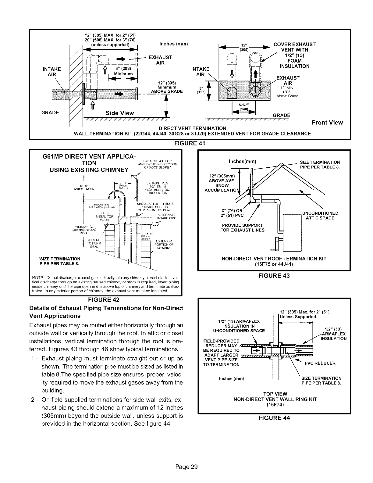
INTAKE
AIR
GRADE
//
//
//
//
!!!i!i!!ii_:i_:i_:i_:i_:i_:i_:ii:iii!:!iiiiiiiiiiiii!;
12" (305) MAX. for 2" (51)
20" (508) MAX. for 3" (76)
_.=(unless supported)=..= I Inches (rnrn)
U'r'
_ EXHAUST
-L J _ AIR
LI_I _ 8" (203) ]
]- I_ I U Minimu._
I I II I"_-- 12"(305)
ABOVE GRADE
Side View
fffffffSffSffSffS_
12"
(305)
INTAKE
AIR
COVER EXHAUST
VENT WITH
1/2" (13)
FOAM
INSULATION
EXHAUST
AIR
5" 12" MIN.
(127) (305)
Above Grade
GRADE
DIRECT VENT TERMINATION
WALL TERMINATION KIT (22G44, 44J40, 30G28 or 81J20) EXTENDED VENT FOR GRADE CLEARANCE
Front View
FIGURE 41
G61MP DIRECT VENT APPLICA-
TION
USING EXISTING CHIMNEY
8 12
(203mm 30_nm)
INTAKE P_PE
FNSULAT_ON(op_al)
SHEET
METAL TOP
PLATE
MINIMUM i2"
(305ram) ABOVE
ROOF
t
*SIZE TERMINATION
PIPE PER TABLE 8.
STRAIGHT-CUT OR
ANGLE-CUT IN DIRECTION
OF ROOF SLOPE *
EXHAUSTVENT
1M' (13ram)
WEATHERPROOF
INSULATOR
SHOULDER OF FITTINGS
PROVIDE SUPPORT
OF PIPE ON TOP PLATE
iALTERNATE
-r--q-,
NOTE -Do not discharge exhaust gases directjy into any chimney or vent stack. If ver-
tical discharge through an existing unused chimney or stack is required, insert piping
inside chimney until the pipe open end is above top of chimney and terminate as illus-
trated. In any exterior portion of chimney, the exhaust vent must be insulated.
FIGURE 42
Details of Exhaust Piping Terminations for Non-Direct
Vent Applications
Exhaust pipes may be routed either horizontally through an
outside wall or vertically through the roof, In attic or closet
installations, vertical termination through the roof is pre-
ferred. Figures 43 through 46 show typical terminations,
1 - Exhaust piping must terminate straight out or up as
shown, The termination pipe must be sized as listed in
table &The specified pipe size ensures proper veloc-
ity required to move the exhaust gases away from the
building.
2 - On field supplied terminations for side wall exits, ex-
haust piping should extend a maximum of 12 inches
(305mm) beyond the outside wall, unless support is
provided in the horizontal section. See figure 44.
Inches(ram) .,v SIZE TERMINATION
__ -.--_ PIPE PER TABLE 8.
12" (305ram)t _¢// _-
ABOVEAVE./ If_// _
SNOW I AIF/ XX
ACCUMULAT.O :
/II
'/II -A ia- PACE
PROVIDESUPPORT I1 I I
FOR EXHAUST LINES 1.14
NON-DIRECT VENT ROOF TERMINATION KIT
(15F75 or 44J41)
FIGURE 43
1/2" (13) ARMAFLEX
INSULATION IN
UNCONDITIONED SPACE
FIELD-PROVIDED
REDUCER MAY t ......... =_.
BE REQUIRED TO
ADAPT LARGER _
VENT PIPE SIZE =-
TO TERMINATION
Inches (mm)
Pp_
12" (305) Max. for 2" (51)
Unless Supported
_1 1/2" (13)
I.._ARMAFLEX
_._ INSULATION
k_ PVC REDUCER
SIZE TERMINATION
PIPE PER TABLE 8.
TOP VIEW
NON-DIRECT VENT WALL RING KIT
(15F74)
FIGURE 44
Page 29
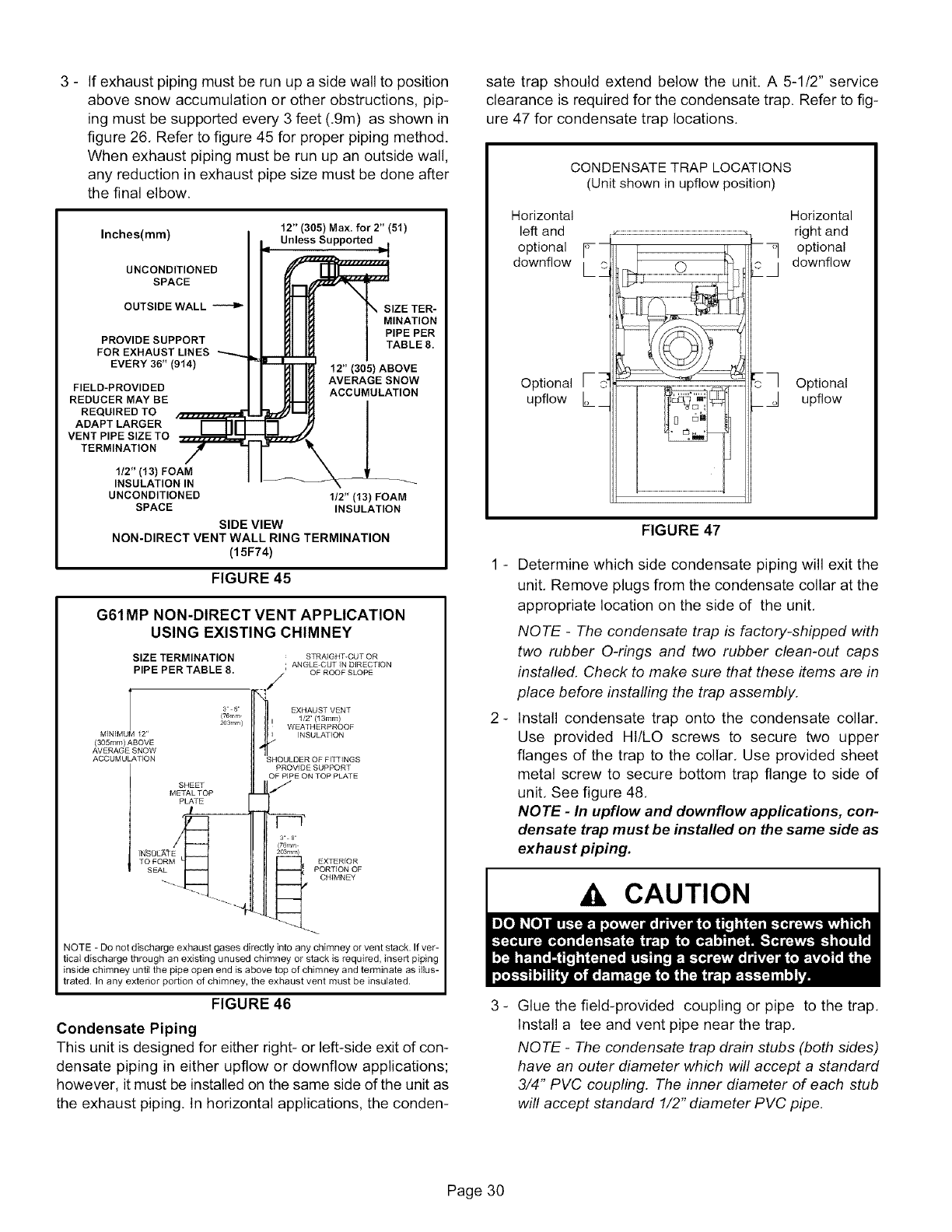
3- Ifexhaustpipingmustberunupasidewalltoposition
abovesnowaccumulationorotherobstructions,pip-
ingmustbesupportedevery3feet(.9m)asshownin
figure26.Refertofigure45forproperpipingmethod.
Whenexhaustpipingmustberunupanoutsidewall,
anyreductioninexhaustpipesizemustbedoneafter
thefinalelbow.
Inches(mm)
UNCONDITIONED
SPACE
OUTSIDE WALL
12" (305) Max. for 2" (51)
L Unless Supported
Lil I_ I MINATION
IHI I_J IPiPE PER
I TABLE8"
12" (305) ABOVE
PROVIDE SUPPORT
FOR EXHAUST LINES
EVERY 30 'I (914)
FIELD-PROVIDED
REDUCER MAY BE
REQUIRED TO /ZZZZ:ZZZZ:Z==_
ADAPT LARGER [_[IF
VENT PIPE SIZE TO
TERMINATION /=
1/2" (13) FOAM
INSULATION IN
UNCONDITIONED 1/2" (13) FOAM
SPACE INSULATION
SIDE VIEW
NON-DIRECT VENT WALL RING TERMINATION
(15F74)
FIGURE 45
G61MP NON-DIRECT VENT APPLICATION
USING EXISTING CHIMNEY
SIZE TERMINATION
PIPE PER TABLE 8.
38
(76m_
203mm)
MINIMU 12"
(_5mm)ABOVE
AVERAGE:NOW
ACCUMULATION
SHEET
METALTOP
PLATE
/_SOLAT_
TOFORM
SEAL
STRAIGHT-CUT OR
'ANGLE CUT iN DIRECTION
OF ROOF SLOPE
EXHAUST VENT
1/2" (13rnrn)
WEATHERPROOF
INSULATION
SHOULDER OF FI_INGS
PROVIDE SUPPORT
OF PIPE ON TOP PLATE
3 8
(76ram
203rnm)
EXTERIOR
PORTION OF
CHIMNEY
NOTE -Do not discharge exhaust gases directly into any chimney or vent stack. If ver-
tical discharge through an existing unused chimney or stack is required, insert piping
inside chimney until the pipe open end is above top of chimney and terminate as it]us-
trated. In any exterior portion of chimney, the exhaust vent must be insutated.
FIGURE 46
Condensate Piping
This unit is designed for either right- or left-side exit of con-
densate piping in either upflow or downfiow applications;
however, it must be installed on the same side of the unit as
the exhaust piping. In horizontal applications, the conden-
sate trap should extend below the unit. A 5-1/2" service
clearance is required for the condensate trap. Refer to fig-
ure 47 for condensate trap locations.
CONDENSATE TRAP LOCATIONS
(Unit shown in upfiow position)
Horizontal Horizontal
left and ...................................................right and
optional r-- [_ _ --_] optional
downflow h"i .................................._ ..... _/ downflow
Optional [-- _
upflow L_
_ Optional
_ _ upflow
FIGURE 47
1 - Determine which side condensate piping will exit the
unit. Remove plugs from the condensate collar at the
appropriate location on the side of the unit.
NOTE -The condensate trap is factory-shipped with
two rubber O-rings and two rubber clean-out caps
instafled. Check to make sure that these items are in
place before installing the trap assembly.
2- Install condensate trap onto the condensate collar.
Use provided HI/LO screws to secure two upper
flanges of the trap to the collar, Use provided sheet
metal screw to secure bottom trap flange to side of
unit, See figure 48,
NOTE -In upflow and downflow applications, con-
densate trap must be installed on the same side as
exhaust piping.
CAUTION
3 - Glue the field-provided coupling or pipe to the trap.
Install a tee and vent pipe near the trap.
NOTE -The condensate trap drain stubs (both sides)
have an outer diameter which will accept a standard
3/4" PVC coupling. The inner diameter of each stub
will accept standard 1/2" diameter PVC pipe.
Page 30
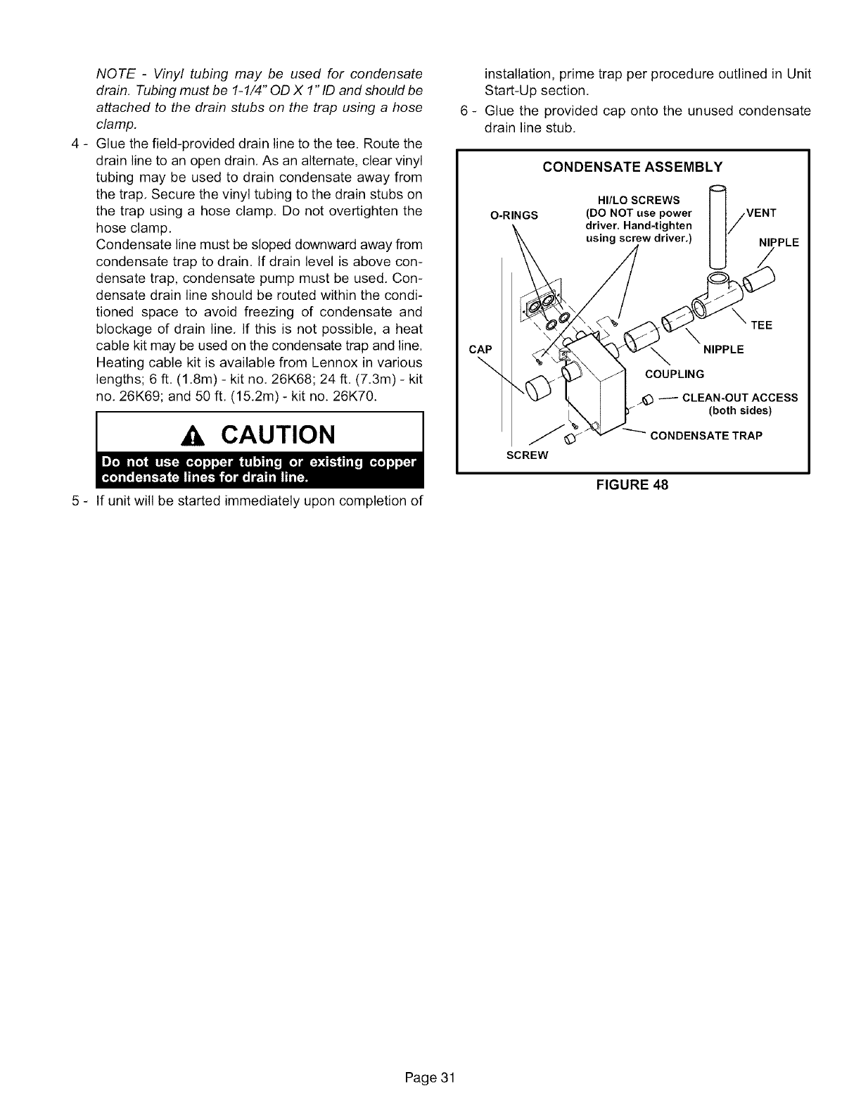
NOTE -Vinyl tubing may be used for condensate
drain. Tubing must be 1-1/4" OD X 1"ID and should be
attached to the drain stubs on the trap using a hose
clamp.
4 - Glue the field-provided drain line to the tee. Route the
drain line to an open drain, As an alternate, clear vinyl
tubing may be used to drain condensate away from
the trap, Secure the vinyl tubing to the drain stubs on
the trap using a hose clamp, Do not overtighten the
hose clamp,
Condensate line must be sloped downward away from
condensate trap to drain, If drain level is above con-
densate trap, condensate pump must be used, Con-
densate drain line should be routed within the condi-
tioned space to avoid freezing of condensate and
blockage of drain line, If this is not possible, a heat
cable kit may be used on the condensate trap and line.
Heating cable kit is available from Lennox in various
lengths; 6 ft. (1.8m) - kit no. 26K68; 24 ft. (7.3m) - kit
no, 26K69; and 50 ft, (15,2m) - kit no. 26K70.
CAUTION
5 - If unit will be started immediately upon completion of
installation, prime trap per procedure outlined in Unit
Start-Up section.
6 - Glue the provided cap onto the unused condensate
drain line stub.
O-RINGS
CONDENSATE ASSEMBLY
HI/LO SCREWS
(DO NOT use power
driver. Hand-tighten
using screw driver.)
/VENT
NIPPLE
CAP
\
SCREW
TEE
NIPPLE
COUPLING
_CLEAN-OUT ACCESS
(both sides)
CONDENSATE TRAP
FIGURE 48
Page 31
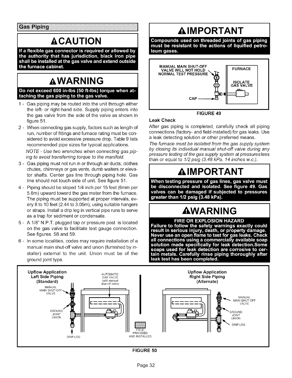
-&CAUTION
,WARNING
AIMPORTANT
1 - Gas piping may be routed into the unit through either
the left- or right-hand side. Supply piping enters into
the gas valve from the side of the valve as shown in
figure 51.
2 - When connecting gas supply, factors such as length of
run, number of fittings and furnace rating must be con-
sidered to avoid excessive pressure drop. Table 9 lists
recommended pipe sizes for typical applications.
NOTE -Use two wrenches when connecting gas pip-
ing to avoid transferring torque to the manifold.
3 - Gas piping must not run in or through air ducts, clothes
chutes, chimneys or gas vents, dumb waiters or eleva-
tor shafts. Center gas line through piping hole. Gas
line should not touch side of unit. See figure 51.
4 - Piping should be sloped 1/4 inch per 15 feet (6mm per
5.6m) upward toward the gas meter from the furnace.
The piping must be supported at proper intervals, ev-
ery 8 to 10 feet (2.44 to 3.05m), using suitable hangers
or straps. Install a drip leg in vertical pipe runs to serve
as a trap for sediment or condensate.
5 - A 1/8" N.P.T. plugged tap or pressure post is located
on the gas valve to facilitate test gauge connection.
See figures 58 and 59.
6 - In some localities, codes may require installation of a
manual main shut-off valve and union (furnished by in-
staller) external to the unit. Union must be of the
ground joint type.
MANUAL MAIN SHUT-OFF
VALVE WILL NOT HOLD --
NORMAL TEST PRESSURE _]_
CAP -------_t_
FURNACE
ISOLATE
GAS VALVE
FIGURE 49
Leak Check
After gas piping is completed, carefully check all piping
connections (factory- and field-installed) for gas leaks. Use
a leak detecting solution or other preferred means.
The furnace must be isolated from the gas supply system
by closing its individual manual shut-off valve during any
pressure testing of the gas supply system at pressures less
than or equal to 1/2 psig (3.48 kPa, 14 inches w.c.).
,IMPORTANT
Upflow Application AUTOMATIC
Left Side Piping GASVALVE
(Standard) (with manual
shut-off valve)
MANUAL
MAIN SHUT-OFF r
VALVE
GROUND
JOINT
UNION
DRIP LEG
r
FIELD
PROVIDED
AND INSTALLED
[
&WARNING
Upflow Application
Right Side Piping
(Alternate)
MANUAL
MAIN SHU%OFF
VALVE
JOINT
UNION
DRIP LEG
FIGURE 50
Page 32
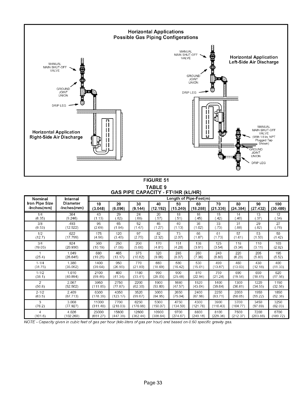
Horizontal Applications
Possible Gas Piping Configerations
M AN U AL
MAIN SHUT-OFF
VALVE
J
GROUND
JOINT
UNION
DRIP LEG
Horizontal Application
Right-Side Air Discharge
MANUAL
MAIN SHUT-OFF _
VALVE
J
GROUND
JOINT
UNION
DRIP LEG
Horizontal Application
Left-Side Air Discharge
MANUAL
MAIN SHUT-OFF
VALVE
["_-- (With 1/8in. NPT
Plugged Tap
Shown)
JOINT
UNION
DRIP LEG
Nominal
Iron Pipe Size
-Inches(ram)
1/4
(6.35)
3/8
(9.53)
1/2
(12.7)
3/4
(19.05)
1
(25.4)
1-1/4
(31.75)
1-1/2
(38.1)
2
(50.8)
2-1/2
(63.5)
3
(76.2)
4
(101.6)
FIGURE 51
TABLE 9
GAS PIPE CAPACITY -FT3/HR (kL/HR)
Internal Length of Pipe-Feet(m)
Diameter 10 20 30 40 50 60 70
-Inches(ram) (3.048) (6.096) (9.144) (12.192) (15.240) (18.288) (21.336)
,364 43 29 24 20 18 16 15
(9.246) (1.13) (.82) (.66) (.57) (.51) (.45) (.42)
.493 95 65 52 45 40 36 33
(12.522) (2.69) (1.84) (1.47) (1.27) (1.13) (1.02) (.73)
.822 175 120 97 82 73 66 61
(17.799) (4.96) (3.40) (2.75) (2.32) (2.07) (1.67) (1.73)
.624 360 250 200 170 151 138 125
(20.930) (10.19) (7.06) (5.66) (4.81) (4.26) (3.91) (3.54)
1.049 660 465 375 320 265 260 240
(26.645) (19.25) (13.17) (10.62) (9.06) (6.07) (7.36) (6.60)
1,380 1400 950 770 660 580 530 490
(35.052) (39.64) (26.90) (21.60) (18.69) (16.42) (15.01) (13.67)
1.610 2100 460 1160 990 900 810 750
(40.694) (59.46) (41.34) (33.41) (28.03) (25.46) (22.94) (21.24)
2,067 3950 2750 2200 1900 1660 1520 1400
(52.502) (111.65) (77.87) (62.30) (53.60) (47.57) (43.04) (39.64)
2,469 6300 4350 3520 3000 2650 2400 2250
(67.713) (176.39) (123.17) (99.67) (84.95) (75.04) (67.96) (63.71)
3,068 11000 7700 6250 5300 4750 4300 3900
(77.927) (311.48) (216.03) (176.98) (150.07) (134.50) (121.76) (110.43)
4.026 23000 15800 12800 10900 9700 6600 6100
(102.260) (651.27) (447.39) (362.44) (306.64) (274.67) (249.18) (229.36)
8O
(24.384)
14
(.40)
31
(.88)
57
(1.61)
118
(3.34)
22o
(6.23)
46o
(13.o3)
69o
(19.54)
13oo
(36.81)
2050
(58.05)
3700
(lO4.77)
7500
(212.37)
NOTE - Capacity given in cubic feet of gas per hour (kilo liters of gas per hour) and based on O.60 specific gravity gas.
9O
(27.432)
13
(.37)
29
(.82)
53
(1.50)
110
(3.11)
205
(5.80)
430
(12.18)
650
(18.41)
1220
(34.55)
1950
(55.22)
3450
(97.69)
7200
(203.88)
100
(30.480)
12
(.34)
27
(.76)
5o
(1.42)
lO3
(2.92)
195
(5.52)
400
(11.33)
620
(17.56)
1150
(32.56)
1850
(52.38)
3250
(92.03)
6700
(189.72)
Page 33
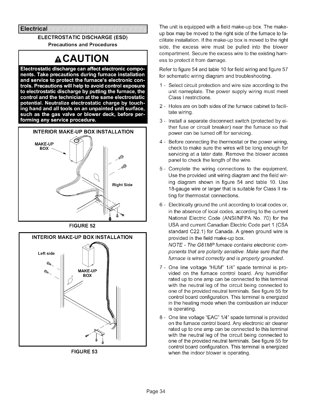
ELECTROSTATIC DISCHARGE (ESD)
Precautions and Procedures
&CAUTION
INTERIOR MAKE-UP BOX INSTALLATION
MAKE-UP
BOX
Right Side
J
6
FIGURE 52
INTERIOR MAKE-UP BOX INSTALLATION
Left _\side __==_
_MAKE-UP
_oBOX
FIGURE 53
The unit is equipped with a field make-up box. The make-
up box may be moved to the right side of the furnace to fa-
cilitate installation, If the make-up box is moved to the right
side, the excess wire must be pulled into the blower
compartment. Secure the excess wire to the existing harn-
ess to protect it from damage,
Refer to figure 54 and table 10 for field wiring and figure 57
for schematic wiring diagram and troubleshooting,
1 - Select circuit protection and wire size according to the
unit nameplate. The power supply wiring must meet
Class I restrictions,
2 - Holes are on both sides of the furnace cabinet to facili-
tate wiring,
3 - Install a separate disconnect switch (protected by ei-
ther fuse or circuit breaker) near the furnace so that
power can be turned off for servicing,
4 - Before connecting the thermostat or the power wiring,
check to make sure the wires will be long enough for
servicing at a later date, Remove the blower access
panel to check the length of the wire,
5- Complete the wiring connections to the equipment.
Use the provided unit wiring diagram and the field wir-
ing diagram shown in figure 54 and table 10, Use
18-gauge wire or larger that is suitable for Class II ra-
ting for thermostat connections,
6 - Electrically ground the unit according to local codes or,
in the absence of local codes, according to the current
National Electric Code (ANSI/NFPA No, 70) for the
USA and current Canadian Electric Code part 1 (CSA
standard C22.1) for Canada, A green ground wire is
provided in the field make-up box.
NOTE -The G61MP furnace contains electronic com-
ponents that are polarity sensitive. Make sure that the
furnace is wired correctly and is properly grounded.
7- One line voltage "HUM" 1/4" spade terminal is pro-
vided on the furnace control board. Any humidifier
rated up to one amp can be connected to this terminal
with the neutral leg of the circuit being connected to
one of the provided neutral terminals. See figure 55 for
control board configuration. This terminal is energized
in the heating mode when the combustion air inducer
is operating,
8 - One line voltage "EAC" 1/4" spade terminal is provided
on the furnace control board, Any electronic air cleaner
rated up to one amp can be connected to this terminal
with the neutral leg of the circuit being connected to
one of the provided neutral terminals, See figure 55 for
control board configuration, This terminal is energized
when the indoor blower is operating,
Page 34
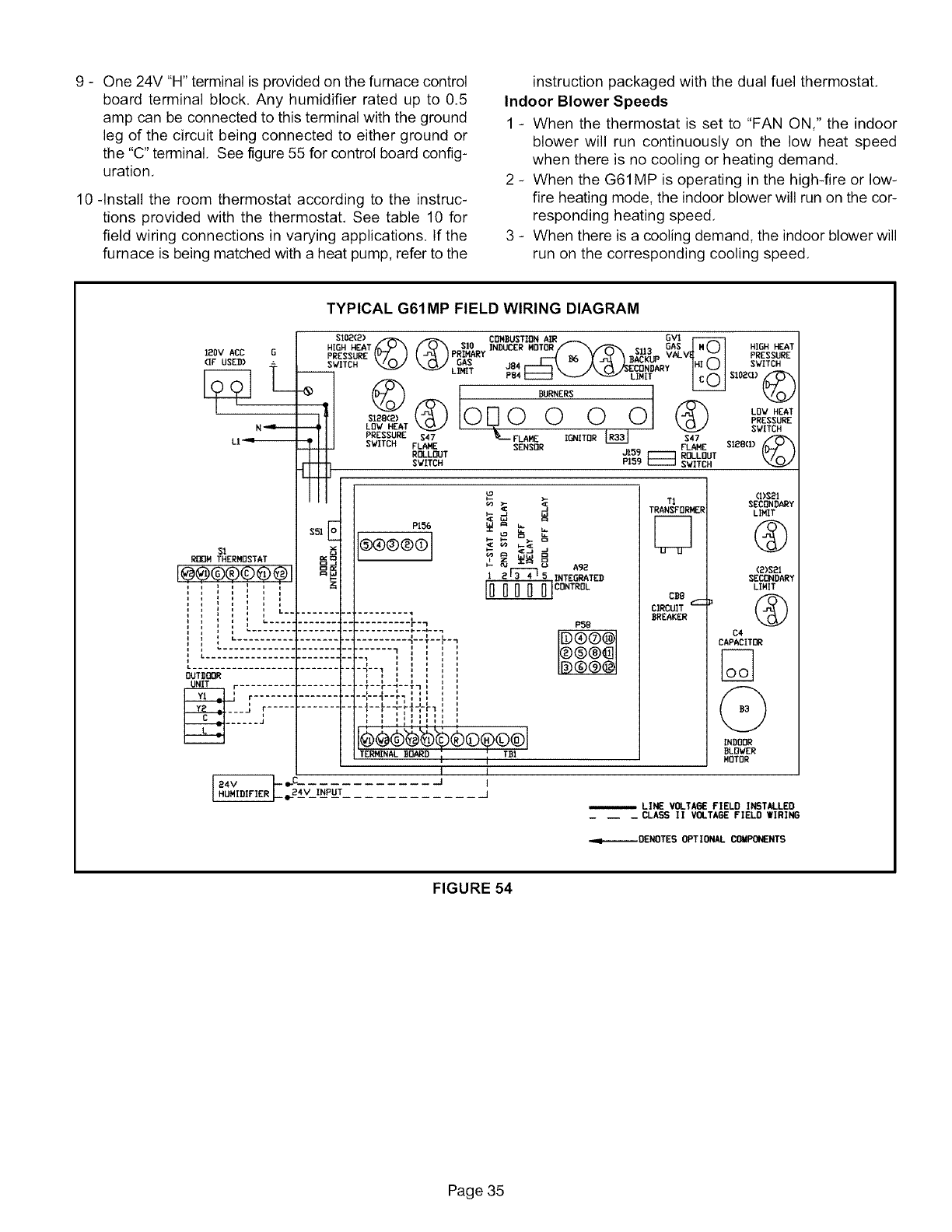
9 - One24V"H"terminalisprovidedonthefurnacecontrol
boardterminalblock.Anyhumidifierratedup to 0.5
ampcanbeconnectedtothisterminalwiththeground
legof thecircuitbeingconnectedto eithergroundor
the"C"terminal,Seefigure55forcontrolboardconfig-
uration,
10-Installthe roomthermostataccordingtothe instruc-
tionsprovidedwiththethermostat,Seetable10for
fieldwiringconnectionsin varyingapplications.Ifthe
furnaceisbeingmatchedwithaheatpump,refertothe
instructionpackagedwiththedualfuelthermostat,
Indoor Blower Speeds
1 - When the thermostat is set to "FAN ON," the indoor
blower will run continuously on the low heat speed
when there is no cooling or heating demand.
2 - When the G61MP is operating in the high-fire or low-
fire heating mode, the indoor blower will run on the cor-
responding heating speed,
3 - When there is a cooling demand, the indoor blower will
run on the corresponding cooling speed.
TYPICAL G61MP FIELD WIRING DIAGRAM
120V ACC G
LI _1 .
SLOB(2) _ _ COMBUSTION AIR ECDNDARYGVI
HIGH HEAT SIO INI]UCER ROTOR S 13 GAS M 0NIGH HEAT
PRIMARY _D_KUP V/_V[ "410SVITCH
PRESSURE PRESSURE
SVITCH L"G_S_zmll Jg4
BURRERS,,OStBB(2) PRESSURE
-- LOV HEAT SVITCH
PRESSURE $47 FLAME IGNITOR RL_ $47
SWITCH FLAME SENSOR FLAME $12B(I) [_
-- ROLL[)JT ,.;159[------qROt.LOUT
__ SWITCH P159 SWITCH
riil
P5B
I])®®@
®®®G]
TI
TRANSFOR_R
C_8 ,I--
CIRCUIT
BREAKER
(I)S_1
SECONDARY
LIMIT
®
(2)$21
SEC{_qDARY
LIMIT
,®
C4
CAPACITOR
@
INDOOR
BLDVER
MOTOR
LINE VOLTAGE FIELD INSTALLED
___ _BASS II VOLTAGE FIELD WlRINE
_GENOTES OPTIONAL COMPONENTS
FIGURE 54
Page 35
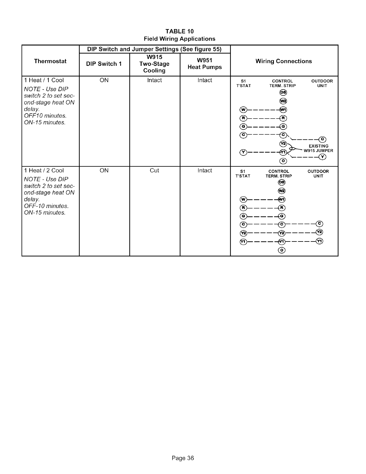
Thermostat
1 Heat/1 Cool
NOTE -Use DiP
switch 2to set sec-
ond-stage heat ON
delay,
QFFIO minutes,
ON-15 minutes.
1 Heat /2 Cool
NOTE -Use DiP
switch 2to set sec-
ond-stage heat ON
delay.
OFF- 10 minutes.
ON-15 minutes.
TABLE 10
Field Wiring Applications
DIP Switch and Jumper Settings (See figure 55)
DIP Switch 1
ON
ON
W915
Two-Stage
Cooling
Intact
Cut
W951
Heat Pumps
Intact
Intact
Wiring Connections
Sl CONTROL OUTDOOR
T'STAT TERM. STRIP UNIT
@
® ®
®. ®
®- _>. ®
®. _ w_'%_ER
@
Sl CONTROL OUTDOOR
T'STAT TERM. STRIP UNIT
® ®
® ®
® ® ®
@. @ @
@. @ @
@
Page 36
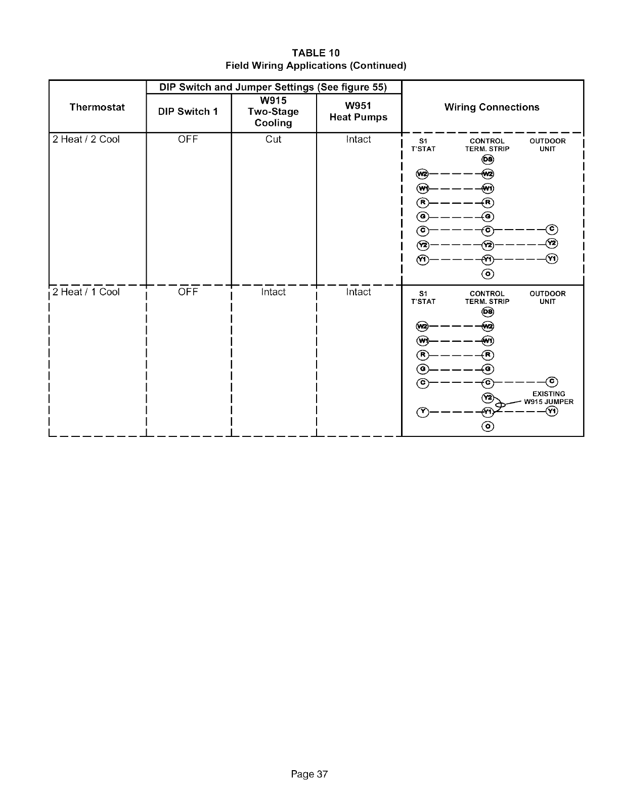
TABLE 10
Field Wiring Applications (Continued)
Thermostat
2 Heat /2 Cool
DIP Switch and Jumper Settings (See figure 55)
W915 W951
DIP Switch 1 Two-Stage Heat Pumps
Cooling
OFF Cut Intact $1
Wiring Connections
CONTROL OUTDOOR
T'STAT TERM. STRIP UNIT
® ®
® ®
® ® ®
@- @ @
@ @ @
@
OUTDOOR
UNIT
®
EXISTING
W915 _._PER
®
2 Heat/1 Cool OFF Intact Intact $1
T'STAT
®
®
®
®
CONTROL
TERM. STRIP
@
4_
®
®
®
Page 37
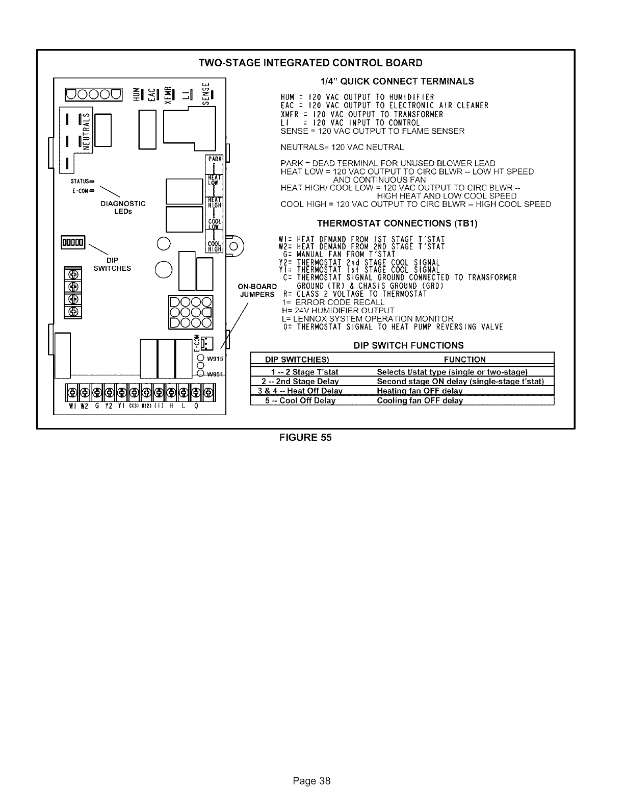
[
[
TWO-STAGE INTEGRATED CONTROL BOARD
L_
(.O
DIP
SWITCHES
D
poooq -1
D
STATU$_ _ _
E-COM= D_D_AGNOSTIC I_1
LEDs
DO00
00(]
000
l]TIo° 0 :
,W95_
Wl W2 G Y2 YI c(3)ll{z)(1)H L 0
ON-BOARD
JUMPERS
1/4"QUICK CONNECT TERMINALS
HUM: 120 VACOUTPUTTO HUMIDIFIER
EAC:120 VACOUTPUTTO ELECTRONICAIR CLEANER
XMFR :120 VAC OUTPUT TO TRANSFORMER
LI : 120 VAC INPUT TO CONTROL
SENSE = 120MAC OUTPUT TO FLAME SENSER
NEUTRALS= 120 VAC NEUTRAL
PARK = DEAD TERMINAL FOR UNUSED BLOWER LEAD
HEAT LOW = 120 MAC OUTPUT TO CIRC BLWR -- LOW HT SPEED
AND CONTINUOUS FAN
HEAT HIGH/COOL LOW = 120 VAC OUTPUT TO CIRC BLWR --
HIGH HEAT AND LOW COOL SPEED
COOL HIGH = 120 VAC OUTPUT TO ClRC BLWR -- HIGH COOL SPEED
THERMOSTAT CONNECTIONS (TB1)
WI: HEAT DEMAND FROM IST STAGE T'STAT
W2: HEAT DEMAND FROM 2ND STAGE T'STAT
G: MANUAL FAN FROM T'STAT
Y2: THERMOSTAT 2nd STAGE COOL SIGNAL
YI: THERMOSTAT l_t STAGE COOL SIGNAL
C: THERMOSTAT SIGNAL GROUND CONNECTED TO TRANSFORMER
GROUND (TR) &CHASIS GROUND (GRD)
R= CLASS 2 VOLTAGE TO THERMOSTAT
1= ERROR CODE RECALL
H= 24V HUMIDIFIER OUTPUT
L= LENNOX SYSTEM OPERATION MONITOR
O= THERMOSTAT SIGNAL TO HEAT PUMP REVERSING VALVE
DIP SWITCH FUNCTIONS
DIP SWITCH(ES)
1-- 2 Staqe T'stat
2-- 2nd Staqe Delay
3&4-- Heat Off Delay
5-- Cool Off Delay
FUNCTION
Selects t/stat type (sin qle or two-staqe)
Second staqe ON delay (sin qle-staqe t'stat)
Heatinq fan OFF delay
Cooling fan OFF delay
FIGURE 55
Page 38
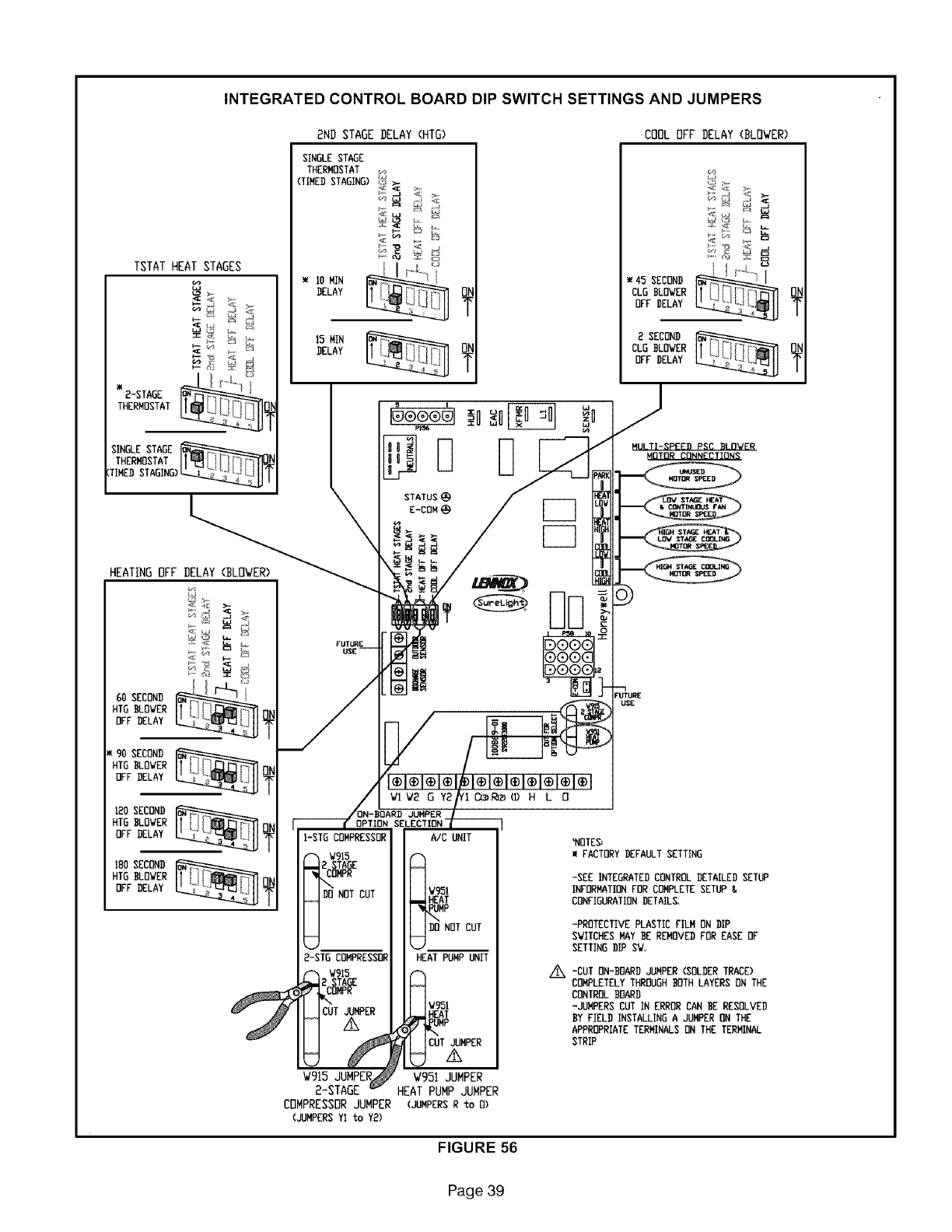
INTEGRATED CONTROL BOARD DIP SWITCH SETTINGS AND JUMPERS
TSTAT HEAT STAGES
:- _°_ t# ,:z:_
2-STAGE
THERMOSTAT
SINGLE STAGE
THERMOSTATI1_ _/_N
:TIMEDSTAGING)
60 SECOND
HTG BLOWER
OFF DELAY
90 SECOND
HTG BLOWER
OFF DELAY
120SECOND
HTG BLOWER
OFF DELAY
180SECOND
HTG BLOWER
OFF DELAY
8NB STAGE BELAY (HTG)
SINGLE STAGE
THERMOSTAT
(TIMEDSTAGING) _:{;i!_ >.
c_
BELAY
15MIN
DELAY
STATUS
Z-COM
Vl V_ G
JUMPER
OPTION _ZLZCTION-
I-STG COMPRESSOR
V915
STAGE
EOMPR
NOT CUT
B-STG COMPRESSOR
W915
CUT JUMPER
Ax
COOL OFF BELAY (BLOWER)
C_Re) (i)H LO
A/C UNIT
V951
EAT
NOT CUT
HEAT PUMP UNIT
V951
CUT/_MPER
W915 V951JUMPER
2-STAGE HEATPUMP JUMPER
COMPRESSOR JUMPER (JUMPERS R _o O)
(JUMPERSYI _o Y_)
45 SECOND
CLG BLOWER
OFF DELAY
8 SECOND
CLG BLOWER
OFF DELAY
L,<,
<I::
'NOTES:
FACTORY DEFAULT SETTING
-SEE INTEGRATEDCONTROL DETAILED SETUP
INFORMATIONFOR COMPLETE SETUP &
CONFIGURATIONDETAILS.
-PROTECTIVE PLASTICFILM ON DIP
SWITCHES MAY BE REMOVED FOR EASE OF
SETTINGDIP SV,
-CUT ON-BOARD JUMPER (SOLDER TRACE)
COMPLETELY THROUGH BOTH LAYERS ON THE
CONTROL BOARD
-JUMPERS CUT IN ERROR CAN BE RESOLVED
BY FIELD INSTALLINGA JUMPER ON THE
APPROPRIATETERMINALSON THE TERMINAL
STRIP
FIGURE 56
Page 39
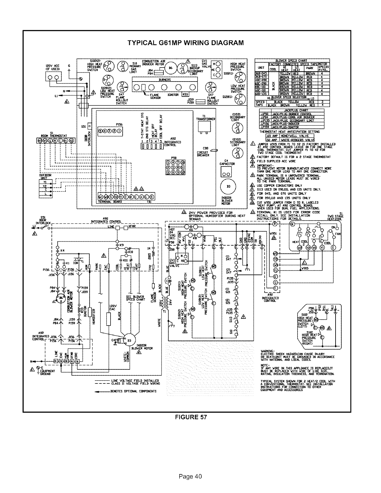
TYPICAL G61MP WIRING DIAGRAM
I_0V ACE G
(IF USED)
LI.._
A
Sl
R[]l_ THERN_TAT
i@@@@@@@1
SI0_2) _ _ C[])4BIJSTIt]NAIR_ ,_ GVI
HIGH HEAT $10 INIKICER NflTOR US HIGH HEAT
PRESSURE PRIMARY _IK3U p VAL PRESSORE
_'_" F134r"""-'1 v _ LIRIT SI_(1)
dR@ Iono o o o @
N>- (I)_I
[RANSFr__9_R UNIT
S5I _ P156
................ '(-4--1--_
I_ CONTRoLINTEQ_ATED C_
CIRCUIT
BREAKER
,I I ,
I L ..........
@
(2)Si?,l
SEC(]NDARY
LIMIT
®
C4
CAPACITOR
@
FORMINAL BOARD TD!
(
A_
INTEGRATEDCONTROL
IM
_ovoR
Nt]TOR
A
ZL_ _4V POVER PROVII_D FOR
OPTIONAL HUMIDIFIER I_JRING HEAT
l_NAN])
I
I
I
-- LINE VTITAGE FIELD INSTALLED
.... _AS_ II VOLTA_ FIELD VIRIN_
-_REk_]TES _TIDEb_. C])_NPONERTS
A
A
BLO_OR S_D CHART
I],_A_IHEA*I IAVAIL,
UNIT CCOL H1 LD PARK SPEEDS
XSD-045 IYELLOVIREB I_R ( 4(
II_RG_NiY__LOvlReD I 4I
IOR_VN IYELLDVI ReD )4 1
-_:_ I]_;]VN _YELLOVI RED I4I
.i IR_,," _'ELLOVIReD I 4I
BOC-IIO mIDROVN IYELLOVI I_) I 4I
_])-I BROVN YELLDV RED 4
_._:KREU]) CHART
J_ JACK/PLU_T_ AIR INI_UFJ_R l
J,PI3_ JACK/PLUG SECI]N_ARY LIMIT )
J156 JACK/REUG-INBUCER
THERROSTAT H_AT ANTICIPATION SETTIt_
JUMPER V915 FROM YI TO YE IS FACTORY INSTALLED
AT A92 CONTROL BOA_& LEAVE IN FOR ONE STA£,E
COCL THERF_)TAT, CUT JUROR YI TO Y_ FOR
TV_ STA6E COOL THERNDSTAT
F_TEIRY _FAt,'LT IS FOR A _ STAGE TReRNOSTAT
FIELD SUPPLIED ACE VIRE
I_TANT-
TO PR£V_NT MOTOR DORNOUT,NEVER CQNt_CT MORE
THAN ONE MOTOR LEAD TO ANY OHE CONNECTION,
PARK TERNINAL IS A L_OVERED TERMINAL,
ALL L_4USED MOTOR LEADS F_;T RE WIRe])
TO THE PARK TERMINAL,
USE _R E_'_T_ O_T
0113 USE]) l_ 090,110, AND 13'3L_ITS DI@.Y.
FOR 045, AND 070 UNITS ONLY
FOR 090,110 AN]) 135 UNITS ONLy
CUT V951 JUMPER FROR 0TO R, LAELED
"HEAT PLkVP% AT Ag2 CONTROL _OARD,
VFEN USE]) FOR _ F[J_L hPPLICAT_
TERMINAL #1 IS USED FDR ERROR CODE
RECALL ONLy, SEE INSTALLATIDN TVD STA_
Z& HE _1
k @@@@ _))
®1
A92
INTEGRATE])
CONTROL
TYPICAL SYSTEN SHOVN FOR ]) H[AT/_ _ VITH
ACONV_NTD_NAL TJ_J_JSTAT, _EE INSTALLAT])_
INSTRUCTIONS FOR EONReCTION TO OTHER
E_IPReNT AND ACCESSORIES
FIGURE 57
Page 40
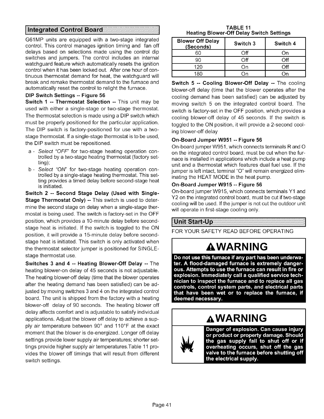
G61MPunitsareequippedwitha two-stageintegrated
control.Thiscontrolmanagesignitiontimingand fanoff
delaysbasedon selectionsmadeusingthecontroldip
switchesandjumpers.Thecontrolincludesan internal
watchguardfeaturewhichautomaticallyresetstheignition
controlwhenit hasbeenlockedout.Afteronehourofcon-
tinuousthermostatdemandforheat,thewatchguardwill
breakandremakethermostatdemandto thefurnaceand
automaticallyresetthecontroltorelightthefurnace.
DIPSwitchSettings--Figure56
Switch1 -- ThermostatSelection-- Thisunitmaybe
usedwitheithera single-stageor two-stagethermostat.
ThethermostatselectionismadeusingaDIPswitchwhich
mustbeproperlypositionedfortheparticularapplication.
TheDIPswitchis factory-positionedfor usewitha two-
stagethermostat.Ifasingle-stagethermostatistobeused,
theDIPswitchmustberepositioned.
a - Select "OFF' for two-stage heating operation con-
trolled by a two-stage heating thermostat (factory set-
ting);
b- Select "QN" for two-stage heating operation con-
trolled by a single-stage heating thermostat. This set-
ting provides a timed delay before second-stage heat
is initiated.
Switch 2 -- Second Stage Delay (Used with Single-
Stage Thermostat Only) -- This switch is used to deter-
mine the second stage on delay when a single-stage ther-
mostat is being used. The switch is factory-set in the OFF
position, which provides a 10-minute delay before second-
stage heat is initiated. If the switch is toggled to the ON
position, it will provide a 15-minute delay before second-
stage heat is initiated. This switch is only activated when
the thermostat selector jumper is positioned for SINGLE-
stage thermostat use.
Switches 3 and 4 -- Heating Blower-Off Delay -- The
heating blower-on delay of 45 seconds is not adjustable.
The heating blower-off delay (time that the blower operates
after the heating demand has been satisfied) can be ad-
justed by moving switches 3 and 4 on the integrated control
board. The unit is shipped from the factory with a heating
blower-off delay of 90 seconds. The heating blower off
delay affects comfort and is adjustable to satisfy individual
applications. Adjust the blower off delay to achieve a sup-
ply air temperature between 90° and 110°F at the exact
moment that the blower is de-energized. Longer off delay
settings provide lower supply air temperatures; shorter set-
tings provide higher supply air temperatures.Table 11 pro-
vides the blower off timings that will result from different
switch settings.
TAB LE 11
Heating Blower-Off Delay Switch Settings
Blower Off Delay Switch 3 Switch 4
(Seconds)
60 Off On
90 Off Off
120 On Off
180 On On
Switch 5 -- Cooling Blower-Off Delay -- The cooling
blower-off delay (time that the blower operates after the
cooling demand has been satisfied) can be adjusted by
moving switch 5 on the integrated control board. The
switch is factory-set in the OFF position, which provides a
cooling blower-off delay of 45 seconds. If the switch is
toggled to the ON position, it will provide a 2-second cool-
ing blower-off delay
On-Board Jumper W951 -- Figure 56
On-board jumper W951, which connects terminals R and O
on the integrated control board, must be cut when the fur-
nace is installed in applications which include a heat pump
unit and a thermostat which features dual fuel use. If the
jumper is left intact, terminal "O" will remain energized elim-
inating the HEAT MODE in the heat pump.
On-Board Jumper W915 -- Figure 56
On-board jumper W915, which connects terminals Y1 and
Y2 on the integrated control board, must be cut if two-stage
cooling will be used. If the jumper is not cut the outdoor unit
will operate in first-stage cooling only.
FOR YOUR SAFETY READ BEFORE OPERATING
A,WARNING
A,WARNING
Page 41
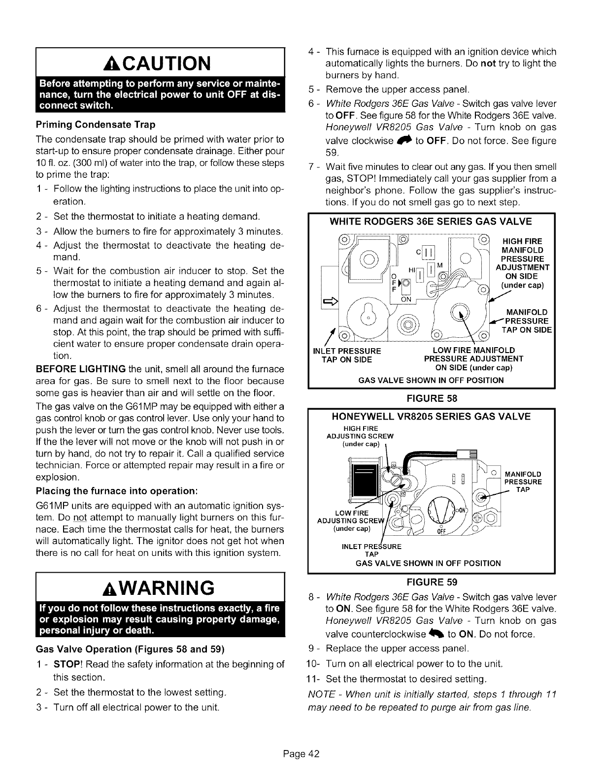
ACAUTION
Priming Condensate Trap
The condensate trap should be primed with water prior to
start-up to ensure proper condensate drainage. Either pour
10fl, oz. (300 ml) of water into the trap, or follow these steps
to prime the trap:
1 - Follow the lighting instructions to place the unit into op-
eration,
2 - Set the thermostat to initiate a heating demand,
3 - Allow the burners to fire for approximately 3 minutes,
4- Adjust the thermostat to deactivate the heating de-
mand,
5 - Wait for the combustion air inducer to stop, Set the
thermostat to initiate a heating demand and again al-
low the burners to fire for approximately 3 minutes.
6- Adjust the thermostat to deactivate the heating de-
mand and again wait for the combustion air inducer to
stop. At this point, the trap should be primed with suffi-
cient water to ensure proper condensate drain opera-
tion,
BEFORE LIGHTING the unit, smell all around the furnace
area for gas, Be sure to smell next to the floor because
some gas is heavier than air and will settle on the floor.
The gas valve on the G61MP may be equipped with either a
gas control knob or gas control lever, Use only your hand to
push the lever or turn the gas control knob. Never use tools,
If the the lever will not move or the knob will not push in or
turn by hand, do not try to repair it, Call a qualified service
technician. Force or attempted repair may result in a fire or
explosion.
Placing the furnace into operation:
G61MP units are equipped with an automatic ignition sys-
tem, Do not attempt to manually light burners on this fur-
nace. Each time the thermostat calls for heat, the burners
will automatically light. The ignitor does not get hot when
there is no call for heat on units with this ignition system,
a,WARNING
Gas Valve Operation (Figures 58 and 59)
1 - STOP! Read the safety information at the beginning of
this section.
2 - Set the thermostat to the lowest setting,
3 - Turn off all electrical power to the unit,
4 - This furnace is equipped with an ignition device which
automatically lights the burners. Do not try to light the
burners by hand,
5 - Remove the upper access panel.
6 - White Rodgers 36E Gas Valve - Switch gas valve lever
to OFF, See figure 58 for the White Rodgers 36E valve,
Honeywell VR8205 Gas Valve - Turn knob on gas
valve clockwise _ to OFF, Do not force, See figure
59,
7 - Wait five minutes to clear out any gas. If you then smell
gas, STOP! Immediately call your gas supplier from a
neighbor's phone. Follow the gas supplier's instruc-
tions. If you do not smell gas go to next step,
WHITE RODGERS 36E SERIES GAS VALVE
HIGH FIRE
MANIFOLD
PRESSURE
ADJUSTMENT
ON SIDE
(under cap)
MANIFOLD
TAP ON SIDE
INLET PRESSURE LOW FIRE MANIFOLD
TAP ON SIDE PRESSURE ADJUSTMENT
ON SIDE (under cap)
GAS VALVE SHOWN IN OFF POSITION
FIGURE 58
HONEYWELL VR8205 SERIES GAS VALVE
HIGH FIRE
ADJUSTING SCREW
(under cap)
MANIFOLD
PRESSURE
TAP
LOW FIRE
(under cap)
_URE
TAP
GAS VALVE SHOWN IN OFF POSITION
FIGURE 59
8 - White Rodgers 36E Gas Valve - Switch gas valve lever
to ON. See figure 58 for the White Rodgers 36E valve,
Honeywell VR8205 Gas Valve - Turn knob on gas
valve counterclockwise _ to ON, Do not force.
9 - Replace the upper access panel,
10- Turn on all electrical power to to the unit,
11- Set the thermostat to desired setting,
NOTE -When unit is initially started, steps 1 through 11
may need to be repeated to purge air from gas fine.
Page 42
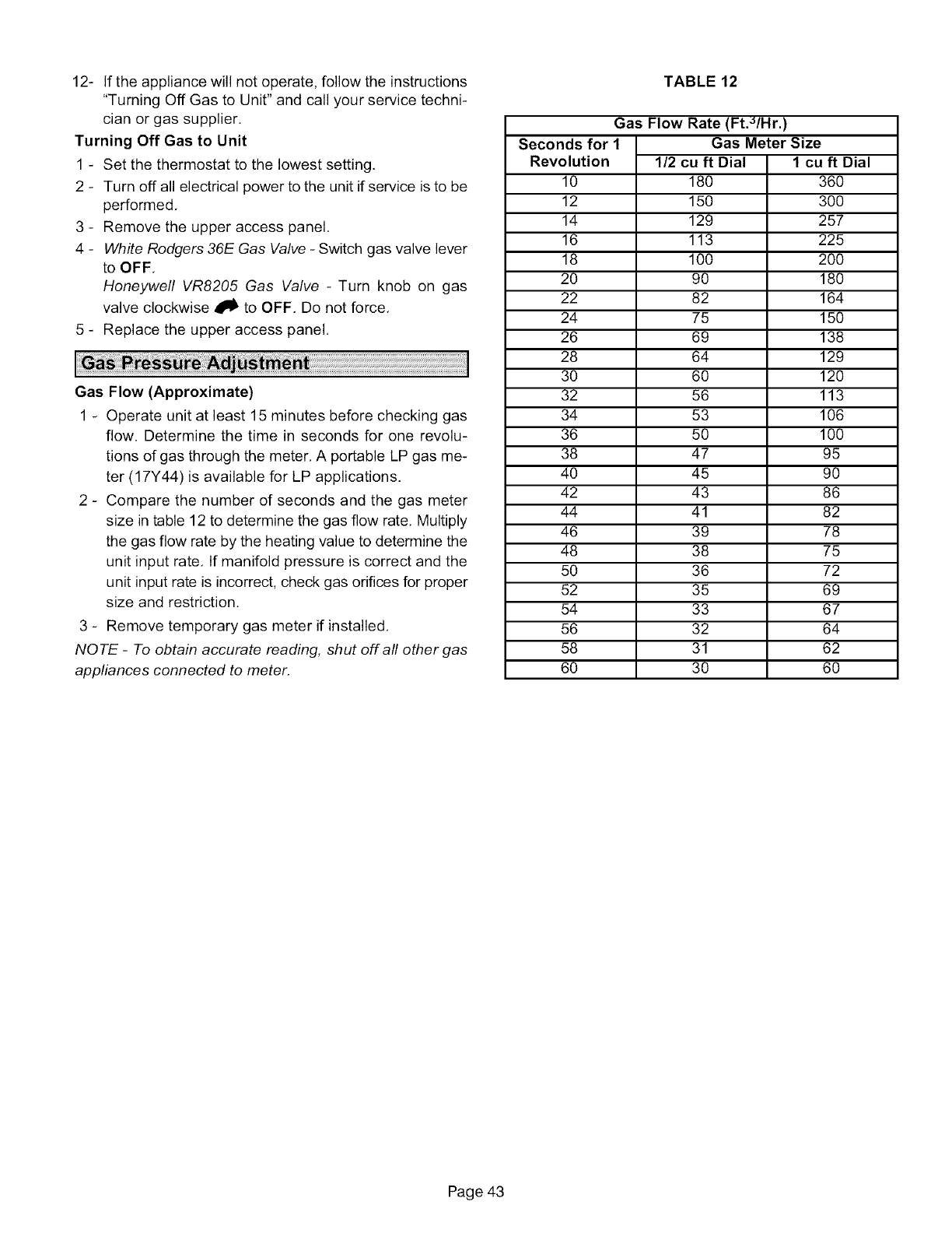
12- Iftheappliancewillnotoperate,followtheinstructions
"TurningOffGastoUnit"andcallyourservicetechni-
cianor gas supplier.
Turning Off Gas to Unit
1-Set the thermostat to the lowest setting,
2 - Turn off all electrical power to the unit if service is to be
performed,
3 - Remove the upper access panel.
4 - White Rodgers 36E Gas Valve - Switch gas valve lever
to OFF,
Honeywefl VR8205 Gas Valve - Turn knob on gas
valve clockwise _ to OFF, Do not force,
5 - Replace the upper access panel,
Gas Flow (Approximate)
1-Operate unit at least 15 minutes before checking gas
flow. Determine the time in seconds for one revolu-
tions of gas through the meter, A portable LP gas me-
ter (17Y44) is available for LP applications.
2 - Compare the number of seconds and the gas meter
size in table 12 to determine the gas flow rate, Multiply
the gas flow rate by the heating value to determine the
unit input rate, If manifold pressure is correct and the
unit input rate is incorrect, check gas orifices for proper
size and restriction,
3 - Remove temporary gas meter if installed,
NOTE- To obtain accurate reading, shut off all other gas
appliances connected to meter.
TABLE 12
Gas Flow Rate (Ft._/Hr.)
Seconds for 1
Revolution
10
12
14
16
18
2O
22
24
26
28
30
32
34
36
38
40
42
44
46
48
50
52
54
56
58
60
Gas Meter Size
1/2 cu ft Dial
180
150
129
113
100
9O
82
75
69
64
60
56
53
50
47
45
43
41
39
38
36
35
33
32
31
30
1 cu ft Dial
36O
30O
257
225
2OO
180
164
150
138
129
120
113
106
100
95
90
86
82
78
75
72
69
67
64
62
60
Page 43
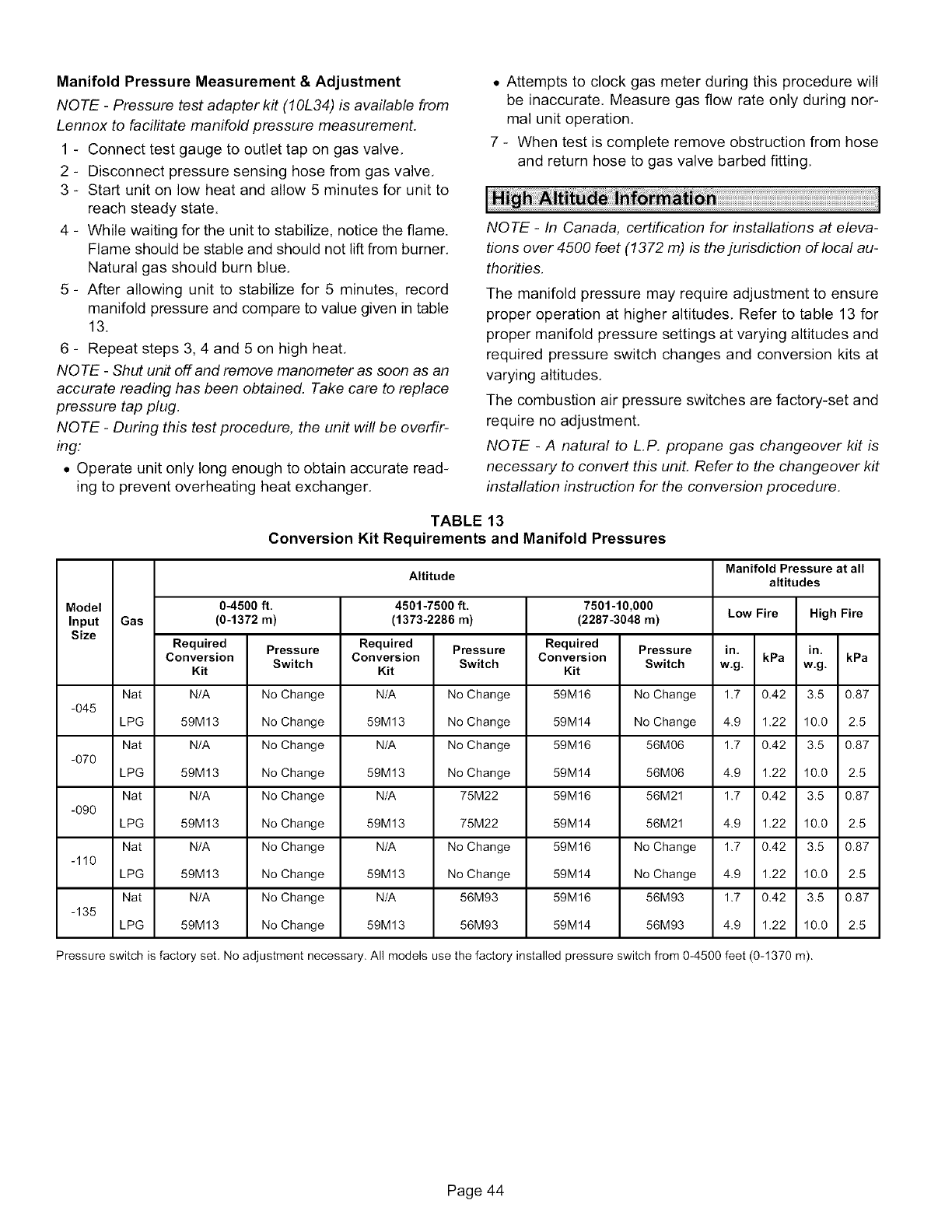
Manifold Pressure Measurement & Adjustment
NOTE -Pressure test adapter kit (10L34) is available from
Lennox to facilitate manifold pressure measurement.
1 - Connect test gauge to outlet tap on gas valve,
2 - Disconnect pressure sensing hose from gas valve,
3 - Start unit on low heat and allow 5 minutes for unit to
reach steady state.
4 - While waiting for the unit to stabilize, notice the flame.
Flame should be stable and should not lift from burner,
Natural gas should burn blue,
5 - After allowing unit to stabilize for 5 minutes, record
manifold pressure and compare to value given in table
13.
6 - Repeat steps 3, 4 and 5 on high heat,
NO TE -Shut unit off and remove manometer as soon as an
accurate reading has been obtained. Take care to replace
pressure tap plug.
NOTE -During this test procedure, the unit will be oveffir-
ing:
• Operate unit only long enough to obtain accurate read-
ing to prevent overheating heat exchanger.
• Attempts to clock gas meter during this procedure will
be inaccurate. Measure gas flow rate only during nor-
mal unit operation.
7 - When test is complete remove obstruction from hose
and return hose to gas valve barbed fitting,
NOTE -In Canada, certification for installations at eleva-
tions over 4500 feet (1372 m) is the jurisdiction of local au-
thorities.
The manifold pressure may require adjustment to ensure
proper operation at higher altitudes, Refer to table 13 for
proper manifold pressure settings at varying altitudes and
required pressure switch changes and conversion kits at
varying altitudes,
The combustion air pressure switches are factory-set and
require no adjustment,
NOTE -A natural to L.P. propane gas changeover kit is
necessary to convert this unit. Refer to the changeover kit
installation instruction for the conversion procedure.
TABLE 13
Conversion Kit Requirements and Manifold Pressures
Altitude Manifold Pressure at all
altitudes
Model 0-4500 ft. 4501-7500 ft. 7501-10,000
Input Gas (0-1372 m) (1373-2286 m) (2287-3048 m) Low Fire High Fire
Size
Required Pressure Required Pressure Required Pressure in. in.
Conversion Conversion Conversion kPa kPa
Kit Switch Kit Switch Kit Switch w.g. w.g.
Nat N/A No Change N/A No Change 59M16 No Change 1.7 0.42 3.5 0.87
-045
LPG 59M13 No Change 59M13 No Change 59M14 No Change 4.9 1.22 10.0 2.5
Nat N/A No Change N/A No Change 59M16 56M06 1.7 0.42 3.5 0.87
-070
LPG 59M13 No Change 59M13 No Change 59M14 56M06 4.9 1.22 10.0 2.5
Nat N/A No Change N/A 75M22 59M16 56M21 1.7 0.42 3.5 0.87
-090
LPG 59M13 No Change 59M13 75M22 59M14 56M21 4.9 1.22 10.0 2.5
Nat N/A No Change N/A No Change 59M16 No Change 1.7 0.42 3.5 0.87
-110
LPG 59M13 No Change 59M13 No Change 59M14 No Change 4.9 1.22 10.0 2.5
Nat N/A No Change N/A 56M93 59M16 56M93 1.7 0.42 3.5 0.87
-135
LPG 59M13 No Change 59M13 56M93 59M14 56M93 4.9 1.22 10.0 2.5
Pressure switch is factory set. No adjustment necessary. All models use the factory installed pressure switch from 0-4500 feet (0-1370 m).
Page 44
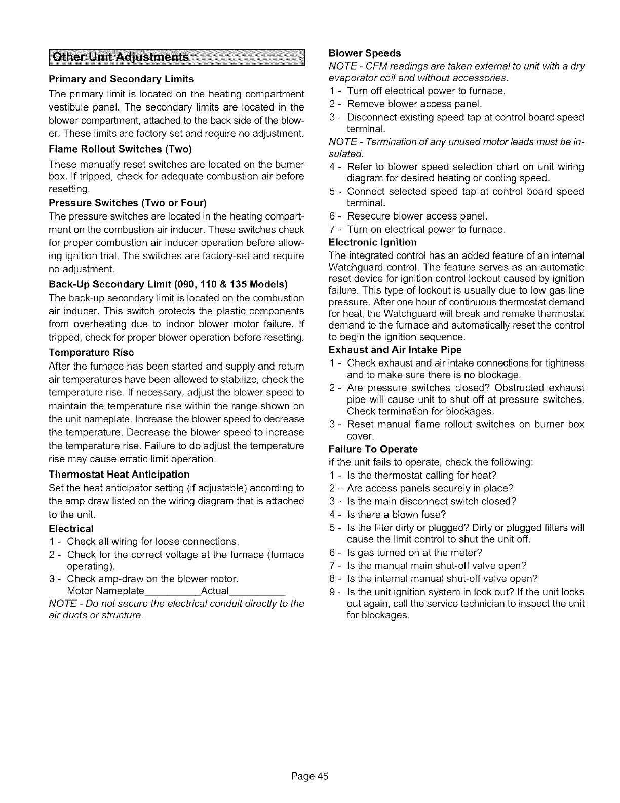
Primary and Secondary Limits
The primary limit is located on the heating compartment
vestibule panel, The secondary limits are located in the
blower compartment, attached to the back side of the blow-
er, These limits are factory set and require no adjustment,
Flame Rollout Switches (Two)
These manually reset switches are located on the burner
box, If tripped, check for adequate combustion air before
resetting,
Pressure Switches (Two or Four)
The pressure switches are located in the heating compart-
ment on the combustion air inducer, These switches check
for proper combustion air inducer operation before allow-
ing ignition trial, The switches are factory-set and require
no adjustment.
Back-Up Secondary Limit (090, 110 &135 Models)
The back-up secondary limit is located on the combustion
air inducer. This switch protects the plastic components
from overheating due to indoor blower motor failure, If
tripped, check for proper blower operation before resetting,
Temperature Rise
After the furnace has been started and supply and return
air temperatures have been allowed to stabilize, check the
temperature rise, If necessary, adjust the blower speed to
maintain the temperature rise within the range shown on
the unit nameplate, Increase the blower speed to decrease
the temperature. Decrease the blower speed to increase
the temperature rise, Failure to do adjust the temperature
rise may cause erratic limit operation,
Thermostat Heat Anticipation
Set the heat anticipator setting (if adjustable) according to
the amp draw listed on the wiring diagram that is attached
to the unit.
Electrical
1 - Check all wiring for loose connections.
2 - Check for the correct voltage at the furnace (furnace
operating).
3 - Check amp-draw on the blower motor.
Motor Nameplate Actual
NOTE - Do not secure the electrical conduit directly to the
air ducts or structure.
Blower Speeds
NOTE -CFM readings are taken external to un# with a dry
evaporator coil and without accessories.
1 - Turn off electrical power to furnace,
2 - Remove blower access panel,
3 - Disconnect existing speed tap at control board speed
terminal.
NO TE -Termination of any unused motor leads must be in-
sulated.
4 - Refer to blower speed selection chart on unit wiring
diagram for desired heating or cooling speed.
5- Connect selected speed tap at control board speed
terminal.
6 - Resecure blower access panel.
7 - Turn on electrical power to furnace.
Electronic Ignition
The integrated control has an added feature of an internal
Watchguard control. The feature serves as an automatic
reset device for ignition control lockout caused by ignition
failure. This type of lockout is usually due to low gas line
pressure, After one hour of continuous thermostat demand
for heat, the Watchguard will break and remake thermostat
demand to the furnace and automatically reset the control
to begin the ignition sequence,
Exhaust and Air Intake Pipe
1 - Check exhaust and air intake connections for tightness
and to make sure there is no blockage,
2- Are pressure switches closed? Obstructed exhaust
pipe will cause unit to shut off at pressure switches.
Check termination for blockages,
3- Reset manual flame rollout switches on burner box
cover.
Failure To Operate
If the unit fails to operate, check the following:
1 - Is the thermostat calling for heat?
2 - Are access panels securely in place?
3 - Is the main disconnect switch closed?
4 - Is there a blown fuse?
5 - Is the filter dirty or plugged? Dirty or plugged filters will
cause the limit control to shut the unit off,
6 - Is gas turned on at the meter?
7 - Is the manual main shut-off valve open?
8 - Is the internal manual shut-off valve open?
9 - Is the unit ignition system in lock out? If the unit locks
out again, call the service technician to inspect the unit
for blockages,
Page 45
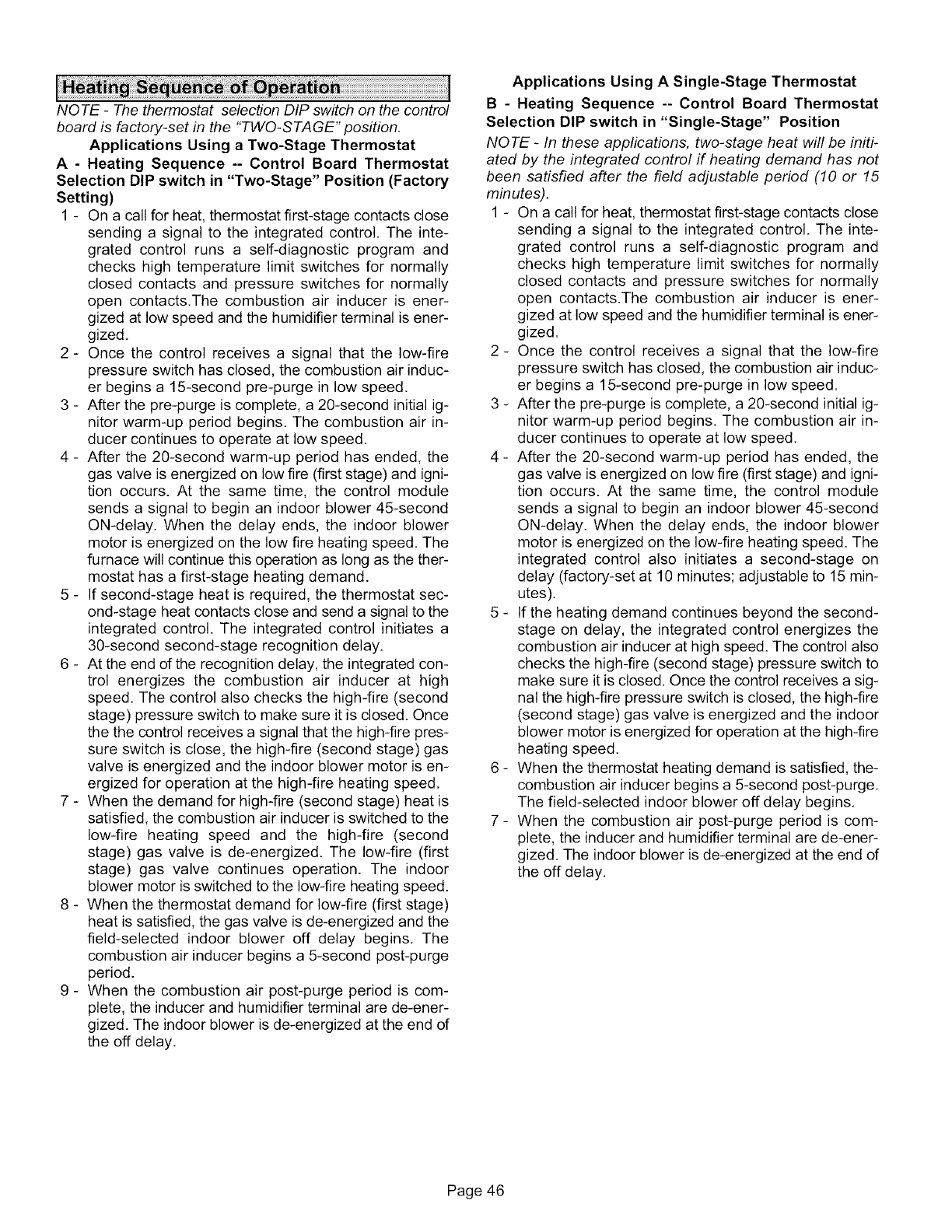
NOTE -The thermostat selection DIP switch on the control
board is factory-set in the "TWO-STAGE" position.
Applications Using a Two-Stage Thermostat
A - Heating Sequence -- Control Board Thermostat
Selection DIP switch in "Two-Stage" Position (Factory
Setting)
1 - On a call for heat, thermostat first-stage contacts close
sending a signal to the integrated control. The inte-
grated control runs a self-diagnostic program and
checks high temperature limit switches for normally
closed contacts and pressure switches for normally
open contacts.The combustion air inducer is ener-
gized at low speed and the humidifier terminal is ener-
gized,
2- Once the control receives a signal that the low-fire
pressure switch has closed, the combustion air induc-
er begins a 15-second pre-purge in low speed.
3 - After the pre-purge is complete, a 20-second initial ig-
nitor warm-up period begins. The combustion air in-
ducer continues to operate at low speed.
4 - After the 20-second warm-up period has ended, the
gas valve is energized on low fire (first stage) and igni-
tion occurs. At the same time, the control module
sends a signal to begin an indoor blower 45-second
ON-delay. When the delay ends, the indoor blower
motor is energized on the low fire heating speed. The
furnace will continue this operation as long as the ther-
mostat has a first-stage heating demand.
5 - If second-stage heat is required, the thermostat sec-
ond-stage heat contacts close and send a signal to the
integrated control. The integrated control initiates a
30-second second-stage recognition delay.
6 - At the end of the recognition delay, the integrated con-
trol energizes the combustion air inducer at high
speed. The control also checks the high-fire (second
stage) pressure switch to make sure it is closed. Once
the the control receives a signal that the high-fire pres-
sure switch is close, the high-fire (second stage) gas
valve is energized and the indoor blower motor is en-
ergized for operation at the high-fire heating speed,
7 - When the demand for high-fire (second stage) heat is
satisfied, the combustion air inducer is switched to the
low-fire heating speed and the high-fire (second
stage) gas valve is de-energized. The low-fire (first
stage) gas valve continues operation. The indoor
blower motor is switched to the low-fire heating speed.
8 - When the thermostat demand for low-fire (first stage)
heat is satisfied, the gas valve is de-energized and the
field-selected indoor blower off delay begins. The
combustion air inducer begins a 5-second post-purge
period.
9 - When the combustion air post-purge period is com-
plete, the inducer and humidifier terminal are de-ener-
gized. The indoor blower is de-energized at the end of
the off delay,
Applications Using A Single-Stage Thermostat
B-Heating Sequence -- Control Board Thermostat
Selection DIP switch in "Single-Stage" Position
NOTE -In these application& two-stage heat will be initi-
ated by the integrated control if heating demand has not
been satisfied after the field adjustable period (10 or 15
minutes).
1 - On a call for heat, thermostat first-stage contacts close
sending a signal to the integrated control. The inte-
grated control runs a self-diagnostic program and
checks high temperature limit switches for normally
closed contacts and pressure switches for normally
open contacts.The combustion air inducer is ener-
gized at low speed and the humidifier terminal is ener-
gized.
2 - Once the control receives a signal that the low-fire
pressure switch has closed, the combustion air induc-
er begins a 15-second pre-purge in low speed.
3 - After the pre-purge is complete, a 20-second initial ig-
nitor warm-up period begins. The combustion air in-
ducer continues to operate at low speed,
4 - After the 20-second warm-up period has ended, the
gas valve is energized on low fire (first stage) and igni-
tion occurs. At the same time, the control module
sends a signal to begin an indoor blower 45-second
ON-delay. When the delay ends, the indoor blower
motor is energized on the low-fire heating speed. The
integrated control also initiates a second-stage on
delay (factory-set at 10 minutes; adjustable to 15 min-
utes).
5 - If the heating demand continues beyond the second-
stage on delay, the integrated control energizes the
combustion air inducer at high speed. The control also
checks the high-fire (second stage) pressure switch to
make sure it is closed. Once the control receives a sig-
nal the high-fire pressure switch is closed, the high-fire
(second stage) gas valve is energized and the indoor
blower motor is energized for operation at the high-fire
heating speed.
6 - When the thermostat heating demand is satisfied, the-
combustion air inducer begins a 5-second post-purge,
The field-selected indoor blower off delay begins,
7- When the combustion air post-purge period is com-
plete, the inducer and humidifier terminal are de-ener-
gized. The indoor blower is de-energized at the end of
the off delay,
Page 46
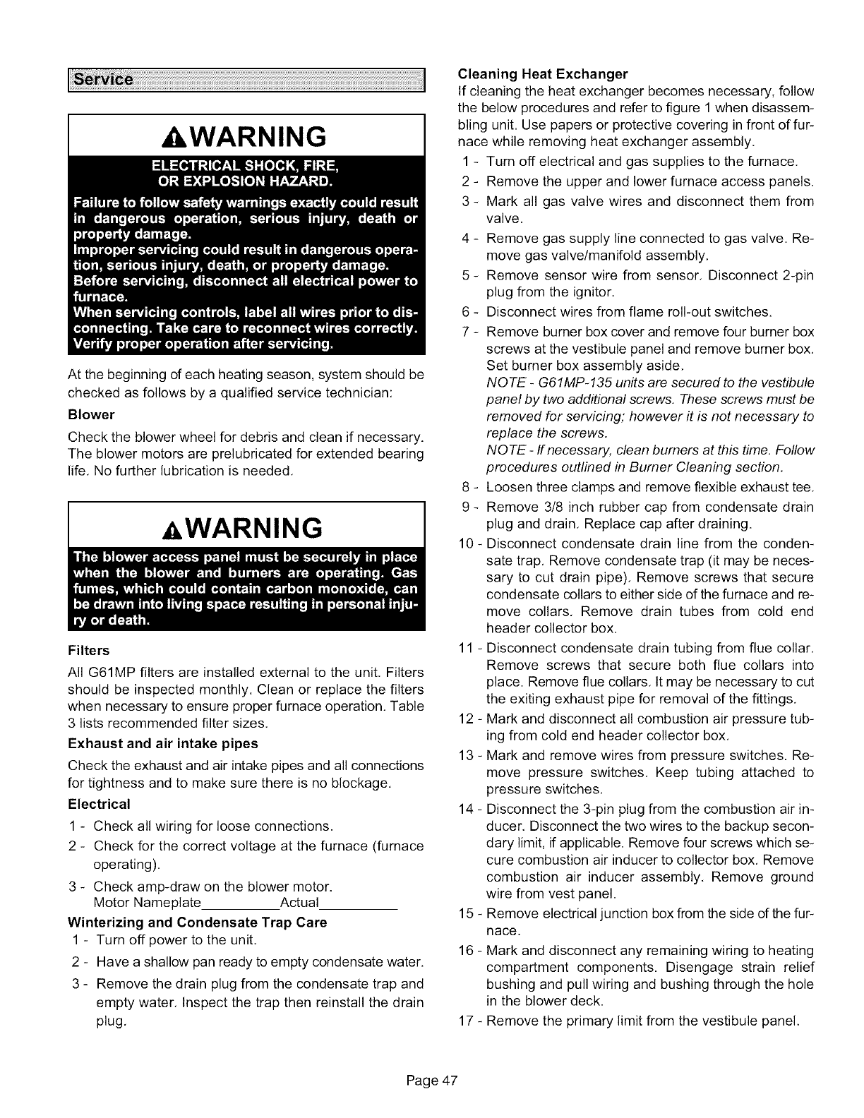
,&WARNING
At the beginning of each heating season, system should be
checked as follows by a qualified service technician:
Blower
Check the blower wheel for debris and clean if necessary.
The blower motors are prelubricated for extended bearing
life, No further lubrication is needed,
,&WARNING
Filters
All G61MP filters are installed external to the unit. Filters
should be inspected monthly. Clean or replace the filters
when necessary to ensure proper furnace operation, Table
3 lists recommended filter sizes,
Exhaust and air intake pipes
Check the exhaust and air intake pipes and all connections
for tightness and to make sure there is no blockage,
Electrical
1 - Check all wiring for loose connections.
2 - Check for the correct voltage at the furnace (furnace
operating),
3 - Check amp-draw on the blower motor.
Motor Nameplate Actual
Winterizing and Condensate Trap Care
1 - Turn off power to the unit,
2 - Have a shallow pan ready to empty condensate water.
3 - Remove the drain plug from the condensate trap and
empty water, Inspect the trap then reinstall the drain
plug,
Cleaning Heat Exchanger
If cleaning the heat exchanger becomes necessary, follow
the below procedures and refer to figure 1 when disassem-
bling unit. Use papers or protective covering in front of fur-
nace while removing heat exchanger assembly.
1 - Turn off electrical and gas supplies to the furnace.
2 - Remove the upper and lower furnace access panels.
3 - Mark all gas valve wires and disconnect them from
valve.
4 - Remove gas supply line connected to gas valve, Re-
move gas valve/manifold assembly,
5 - Remove sensor wire from sensor, Disconnect 2-pin
plug from the ignitor,
6 - Disconnect wires from flame roll-out switches.
7 - Remove burner box cover and remove four burner box
screws at the vestibule panel and remove burner box,
Set burner box assembly aside,
NOTE -G61MP-135 units are secured to the vestibule
panel by two additional screws. These screws must be
removed for servicing; however it is not necessary to
replace the screws.
NOTE -If necessary, clean burners at this time. Follow
procedures outlined in Burner Cleaning section.
8 - Loosen three clamps and remove flexible exhaust tee,
9 - Remove 3/8 inch rubber cap from condensate drain
plug and drain, Replace cap after draining.
10 - Disconnect condensate drain line from the conden-
sate trap, Remove condensate trap (it may be neces-
sary to cut drain pipe), Remove screws that secure
condensate collars to either side of the furnace and re-
move collars, Remove drain tubes from cold end
header collector box.
11 - Disconnect condensate drain tubing from flue collar,
Remove screws that secure both flue collars into
place. Remove flue collars, It may be necessary to cut
the exiting exhaust pipe for removal of the fittings,
12 - Mark and disconnect all combustion air pressure tub-
ing from cold end header collector box,
13 - Mark and remove wires from pressure switches. Re-
move pressure switches, Keep tubing attached to
pressure switches,
14 - Disconnect the 3-pin plug from the combustion air in-
ducer, Disconnect the two wires to the backup secon-
dary limit, if applicable. Remove four screws which se-
cure combustion air inducer to collector box, Remove
combustion air inducer assembly, Remove ground
wire from vest panel.
15 - Remove electrical junction box from the side of the fur-
nace.
16 - Mark and disconnect any remaining wiring to heating
compartment components. Disengage strain relief
bushing and pull wiring and bushing through the hole
in the blower deck.
17 - Remove the primary limit from the vestibule panel.
Page 47
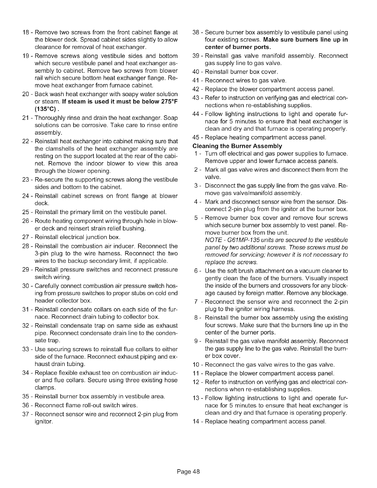
18- Removetwoscrewsfromthefrontcabinetflangeat
theblowerdeck.Spreadcabinetsidesslightlytoallow
clearanceforremovalofheatexchanger,
19- Removescrewsalongvestibulesidesand bottom
whichsecurevestibulepanelandheatexchangeras-
semblyto cabinet.Removetwoscrewsfromblower
railwhichsecurebottomheatexchangerflange,Re-
moveheatexchangerfromfurnacecabinet,
20- Backwashheatexchangerwithsoapywatersolution
orsteam,If steamis usedit mustbebelow275°F
(135°C).
21 - Thoroughly rinse and drain the heat exchanger. Soap
solutions can be corrosive, Take care to rinse entire
assembly.
22 - Reinstall heat exchanger into cabinet making sure that
the clamshells of the heat exchanger assembly are
resting on the support located at the rear of the cabi-
net. Remove the indoor blower to view this area
through the blower opening,
23 - Re-secure the supporting screws along the vestibule
sides and bottom to the cabinet,
24- Reinstall cabinet screws on front flange at blower
deck.
25 - Reinstall the primary limit on the vestibule panel.
26 - Route heating component wiring through hole in blow-
er deck and reinsert strain relief bushing,
27 - Reinstall electrical junction box,
28 - Reinstall the combustion air inducer. Reconnect the
3-pin plug to the wire harness, Reconnect the two
wires to the backup secondary limit, if applicable,
29 - Reinstall pressure switches and reconnect pressure
switch wiring.
30 - Carefully connect combustion air pressure switch hos-
ing from pressure switches to proper stubs on cold end
header collector box,
31 - Reinstall condensate collars on each side of the fur-
nace. Reconnect drain tubing to collector box,
32 - Reinstall condensate trap on same side as exhaust
pipe, Reconnect condensate drain line to the conden-
sate trap.
33 - Use securing screws to reinstall flue collars to either
side of the furnace. Reconnect exhaust piping and ex-
haust drain tubing.
34 - Replace flexible exhaust tee on combustion air induc-
er and flue collars, Secure using three existing hose
clamps,
35 - Reinstall burner box assembly in vestibule area,
36 - Reconnect flame roll-out switch wires,
37 - Reconnect sensor wire and reconnect 2-pin plug from
ignitor,
38 - Secure burner box assembly to vestibule panel using
four existing screws. Make sure burners line up in
center of burner ports.
39- Reinstall gas valve manifold assembly, Reconnect
gas supply line to gas valve,
40 - Reinstall burner box cover,
41 - Reconnect wires to gas valve.
42 - Replace the blower compartment access panel,
43 - Refer to instruction on verifying gas and electrical con-
nections when re-establishing supplies.
44- Follow lighting instructions to light and operate fur-
nace for 5 minutes to ensure that heat exchanger is
clean and dry and that furnace is operating properly,
45 - Replace heating compartment access panel,
Cleaning the Burner Assembly
1 - Turn off electrical and gas power supplies to furnace,
Remove upper and lower furnace access panels,
2 - Mark all gas valve wires and disconnect them from the
valve,
3 - Disconnect the gas supply line from the gas valve, Re-
move gas valve/manifold assembly,
4 - Mark and disconnect sensor wire from the sensor. Dis-
connect 2-pin plug from the ignitor at the burner box.
5 - Remove burner box cover and remove four screws
which secure burner box assembly to vest panel, Re-
move burner box from the unit.
NOTE -G61MP-135 units are secured to the vestibule
panel by two additional screws. These screws must be
removed for servicing; however it is not necessary to
replace the screws.
6 - Use the soft brush attachment on a vacuum cleaner to
gently clean the face of the burners, Visually inspect
the inside dthe burners and crossovers for any block-
age caused by foreign matter, Remove any blockage.
7 - Reconnect the sensor wire and reconnect the 2-pin
plug to the ignitor wiring harness.
8 - Reinstall the burner box assembly using the existing
four screws. Make sure that the burners line up in the
center of the burner ports.
9 - Reinstall the gas valve manifold assembly, Reconnect
the gas supply line to the gas valve, Reinstall the burn-
er box cover,
10 - Reconnect the gas valve wires to the gas valve.
11 - Replace the blower compartment access panel.
12 - Refer to instruction on verifying gas and electrical con-
nections when re-establishing supplies.
13- Follow lighting instructions to light and operate fur-
nace for 5 minutes to ensure that heat exchanger is
clean and dry and that furnace is operating properly,
14 - Replace heating compartment access panel,
Page 48
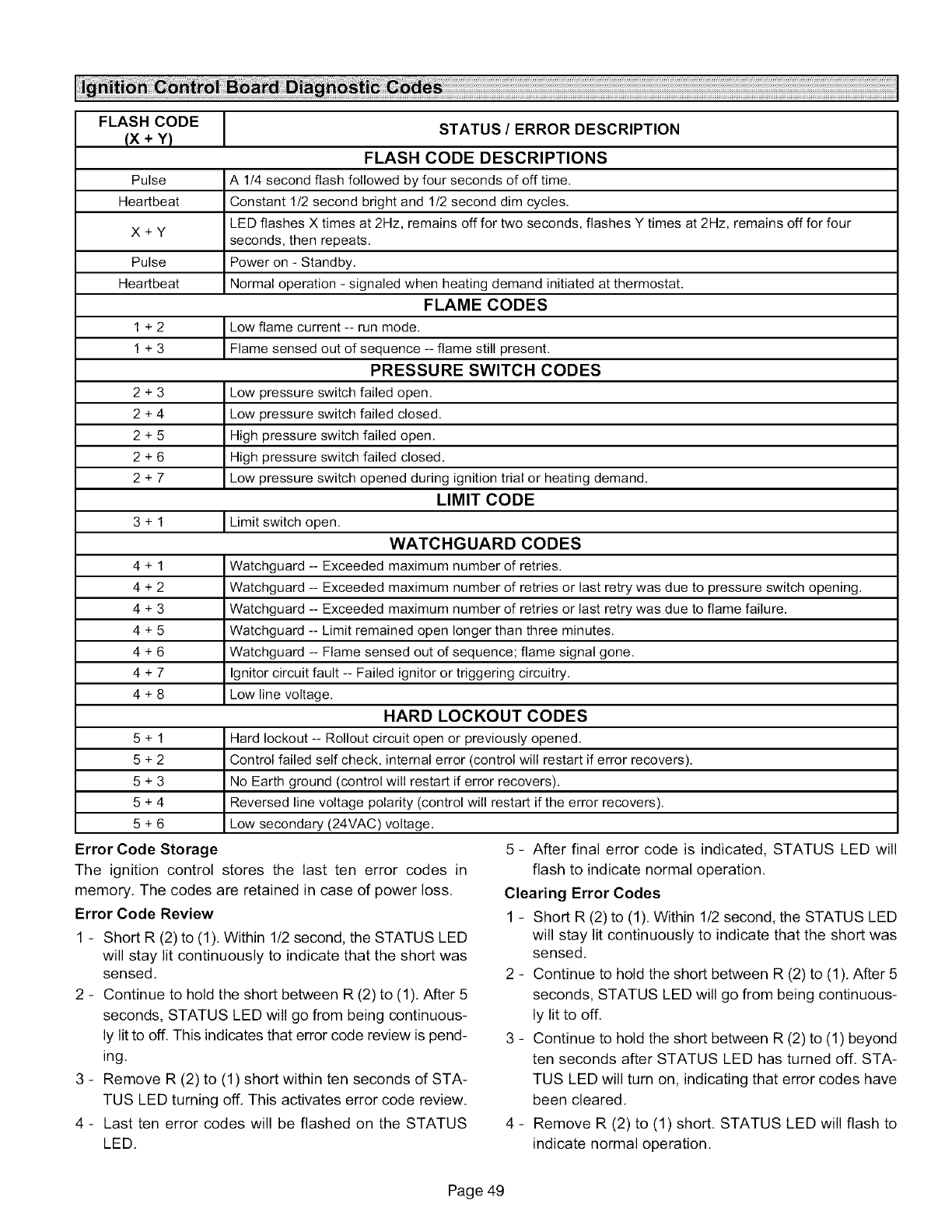
FLASH CODE
(x. Y)
Pulse
Heartbeat
X+Y
Pulse
Heartbeat
1+2
1+3
2+3
2+4
2+5
2+6
2+7
3+1
4+1
4+2
4+3
4+5
4+6
4+7
4+8
5+1
5+2
5+3
5+4
5+6
ISTATUS /ERROR DESCRIPTION
FLASH CODE DESCRIPTIONS
A 1/4 second flash followed by four seconds of off time.
Constant 1/2 second bright and 1/2 second dim cycles.
LED flashes X times at 2Hz, remains off for two seconds, flashes Y times at 2Hz, remains off for four
seconds, then repeats.
Power on - Standby.
Normal operation - signaled when heating demand initiated at thermostat.
FLAME CODES
t Low flame current ---run modem
Flame sensed out of sequence -- flame still present.
PRESSURE SWITCH CODES
Low pressure switch failed open.
Low pressure switch failed closed.
High pressure switch failed open.
High pressure switch failed closed.
Low pressure switch opened during ignition trial or heating demand.
LIMIT CODE
Limit switch open.
WATCI-IGUARD CODES
Watchguard -- Exceeded maximum number of retries.
Watchguard -- Exceeded maximum number of retries or last retry was due to pressure switch opening.
Watchguard -- Exceeded maximum number of retries or last retry was due to flame failure.
Watchguard -- Limit remained open longer than three minutes.
Watchguard -- Flame sensed out of sequence; flame signal gone.
Ignitor circuit fault -- Failed ignitor or triggering circuitry.
Low line voltage.
HARD LOCKOUT CODES
Hard lockout -- Rollout circuit open or previously opened.
Controlfailed self check, internalerror (control will restart if error recovers).
No Earth ground (control will restart if error recovers).
Reversed line voltage polarity (control will restart if the error recovers).
Low secondary (24VAC) voltage.
Error Code Storage
The ignition control stores the last ten error codes in
memory, The codes are retained in case of power loss.
Error Code Review
1 - Short R (2) to (1). Within 1/2 second, the STATUS LED
will stay lit continuously to indicate that the short was
sensed.
2 - Continue to hold the short between R (2) to (1). After 5
seconds, STATUS LED will go from being continuous-
ly lit to off. This indicates that error code review is pend-
ing.
3 - Remove R (2) to (1) short within ten seconds of STA-
TUS LED turning off, This activates error code review.
4 - Last ten error codes will be flashed on the STATUS
LED.
5 - After final error code is indicated, STATUS LED will
flash to indicate normal operation.
Clearing Error Codes
1 - Short R (2) to (1). Within 1/2 second, the STATUS LED
will stay lit continuously to indicate that the short was
sensed.
2 - Continue to hold the short between R (2) to (1). After 5
seconds, STATUS LED will go from being continuous-
ly lit to off,
3 - Continue to hold the short between R (2) to (1) beyond
ten seconds after STATUS LED has turned off. STA-
TUS LED will turn on, indicating that error codes have
been cleared,
4 - Remove R (2) to (1) short. STATUS LED will flash to
indicate normal operation.
Page 49
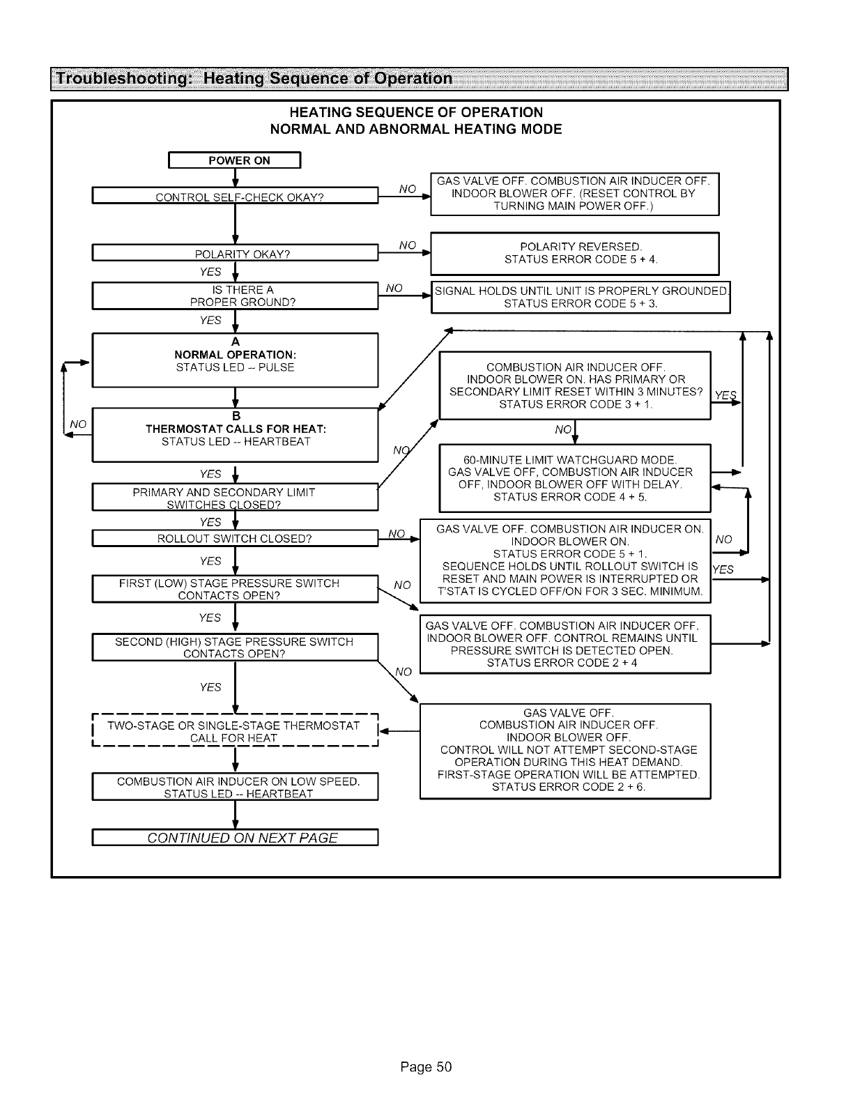
I
I
I
I
I
HEATING SEQUENCE OF OPERATION
NORMAL AND ABNORMAL HEATING MODE
I POWER ON I
CONTROL SELF-CHECK OKAY?
1
POLARITY OKAY?
YES
IS THERE A
PROPER GROUND?
YES _
A
NORMAL OPERATION:
STATUS LED -- PULSE
B
THERMOSTAT CALLS FOR HEAT:
STATUS LED -- HEARTBEAT
YES
PRIMARY AND SECONDARY LIMIT
SWITCHESyEs_LOSED?
ROLLOUT SWITCH CLOSED?
YES _
FIRST (LOW) STAGE PRESSURE SWITCH
CONTACTS OPEN?
YES
I SECOND (HIGH) STAGE PRESSURE SWITCHCONTACTS OPEN?
YES _
r
I TWO-STAGE OR SINGLE-STAGE THERMOSTAT
IL CALL FOR HEAT
I COMBUSTION AIR INDUCER ON LOW SPEED.
STATUS LED -- HEARTBEAT
ICONTINUED ON NEXT PAGE
I_GAS VALVE OFF. COMBUSTION AIR INDUCER OFF.
INDOOR BLOWER OFF. (RESET CONTROL BY
TURNING MAIN POWER OFF.)
__ POLARITY REVERSED.
STATUS ERROR CODE 5 + 4.
__SlGNAL HOLDS UNTIL UNIT IS PROPERLY GROUNDED.
STATUS ERROR CODE 5 + 3.
/I
1
J
I
/
COMBUSTION AIR INDUCER OFF. |
INDOOR BLOWER ON. HAS PRIMARY OR
SECONDARY LIMIT RESET WITHIN 3 MINUTES?
STATUS ERROR CODE 3 + 1.
60-MINUTE LIMIT WATCHGUARD MODE.
GAS VALVE OFF, COMBUSTION AIR INDUCER
OFF, INDOOR BLOWER OFF WITH DELAY.
STATUS ERROR CODE 4 + 5.
GAS VALVE OFF. COMBUSTION AIR INDUCER ON.
INDOOR BLOWER ON.
STATUS ERROR CODE 5 + 1.
SEQUENCE HOLDS UNTIL ROLLOUT SWITCH IS
RESET AND MAIN POWER IS INTERRUPTED OR
T'STAT IS CYCLED OFF/ON FOR 3 SEC. MINIMUM.
GAS VALVE OFF. COMBUSTION AIR INDUCER OFF.
INDOOR BLOWER OFF. CONTROL REMAINS UNTIL
PRESSURE SWITCH IS DETECTED OPEN.
STATUS ERROR CODE 2 + 4
GAS VALVE OFF.
COMBUSTION AIR INDUCER OFF.
INDOOR BLOWER OFF.
CONTROL WILL NOT ATTEMPT SECOND-STAGE
OPERATION DURING THIS HEAT DEMAND.
FIRST-STAGE OPERATION WILL BE ATTEMPTED.
STATUS ERROR CODE 2 + 6.
YES
Page 50
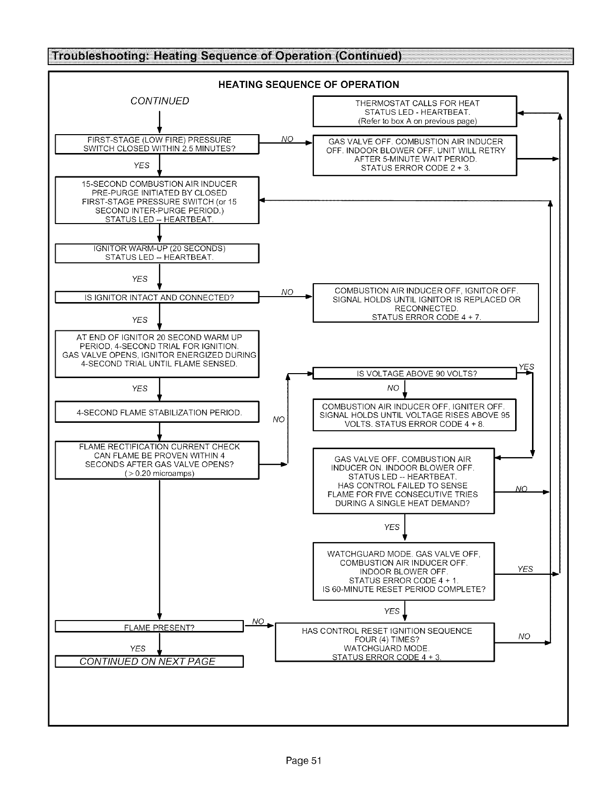
CONTINUED
HEATING SEQUENCE OF OPERATION
NO
NO
---4
I FIRST-STAGE(LOWF,RE)PRESSUREISWITCH CLOSED WITHIN 2.5 MINUTES?
YES _
15-SECOND COMBUSTION AIR INDUCER I
m
i
PRE-PURGE INITIATED BY CLOSED
FIRST-STAGE PRESSURE SWITCH (or 15
SECOND INTER-PURGE PERIOD.)
STATUS LED -- HEARTBEAT.
[ IGNITORWARM-UPI_0SECONDStJSTATUS LED -- HEARTBEAT.
YES _
Iis IGNITOR INTACT AND CONNECTED? i
YES
I AT END OF IGNITOR 20 SECOND WARM UP I
I
PERIOD, 4-SECOND TRIAL FOR IGNITION. I
GAS VALVE OPENS, IGNITOR ENERGIZED DURING
4-SECOND TR AL UNT L FLAME SENSED,
YES
I 4-SECOND FLAME STABILIZATION PERIOD. I NO
I FLAME RECTIFICATION CURRENT CHECK
CAN FLAME BE PROVEN WITHIN 4
SECONDS AFTER GAS VALVE OPENS?
( > 0.20 microamps)
FLAME PRESENT? IN'-_-_°
YES
CONTINUED ON NEXT PAGE J
I
[
THERMOSTAT CALLS FOR HEAT
STATUS LED - HEARTBEAT.
(Refer to box A on previous page)
GAS VALVE OFF. COMBUSTION AIR INDUCER
OFF. INDOOR BLOWER OFF. UNIT WILL RETRY
AFTER 5-MINUTE WAIT PERIOD,
STATUS ERROR CODE 2 + 3.
COMBUSTION AIR INDUCER OFF, IGNITOR OFF.
SIGNAL HOLDS UNTIL IGNITOR IS REPLACED OR
RECONNECTED,
STATUS ERROR CODE 4 + 7.
IS VOLTAGE ABOVE 90 VOLTS?
.o_
COMBUSTION AIR INDUCER OFF, IGNITER OFF.
SIGNAL HOLDS UNTIL VOLTAGE RISES ABOVE 95
VOLTS, STATUS ERROR CODE 4 + 8.
GAS VALVE OFF. COMBUSTION AIR Iql _r
INDUCER ON. INDOOR BLOWER OFF. I
STATUS LED -- HEARTBEAT,
HAS CONTROL FAILED TO SENSE NO
FLAME FOR FIVE CONSECUTIVE TRIES
DURING A SINGLE HEAT DEMAND?
YES lr
WATCHGUARD MODE, GAS VALVE OFF,
COMBUSTION AIR INDUCER OFF.
INDOOR BLOWER OFF.
STATUS ERROR CODE 4 + 1.
IS 60-MINUTE RESET PERIOD COMPLETE?
YES
HAS CONTROL RESET IGNITION SEQUENCE
FOUR (4) TIMES?
WATCHGUARD MODE,
STATUS ERROR CODE 4 + 3. I
J
I
YES
NO
Page 51
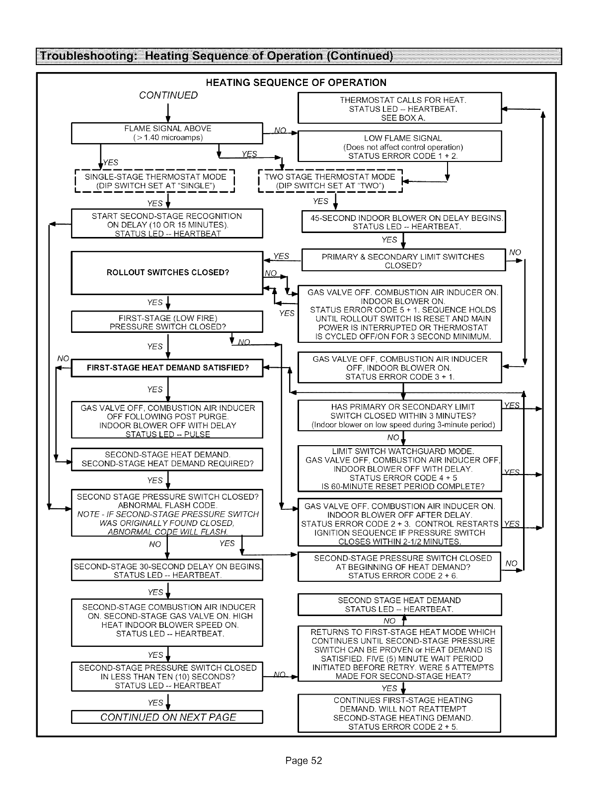
I
I
q
YES
FLAME SIGNAL ABOVE
( > 1.40 microamps)
HEATING SEQUENCE OF OPERATION
CONTINUED THERMOSTAT CALLS FOR HEAT. /
STATUS LED -- HEARTBEAT. I'I1"_
I SEE BOX A. /
LOW FLAME SIGNAL I
YES 1 (Does not operation) I
affect control
" _l I STATUS ERROR CODE 1 + 2. I
I. (DIP SWITCH SET AT 'TWO") j_
YES _
] 45-SECOND INDOOR BLOWER ON DELAY BEGINS.]STATUS LED -- HEARTBEAT.
I
[---_ I
I SINGLE-STAGE THERMOSTAT MODE I
'L (DIP SWITCH SET AT 'SINGLE") I'
YES _
START SECOND-STAGE RECOGNITION
ON DELAY (10 OR 15 MINUTES).
STATUS LED -- HEARTBEAT
ROLLOUT SWITCHES CLOSED?
YES
FIRST-STAGE (LOW FIRE)PRESSURE SWITCH CLOSED?
YES,!
FIRST-STAGE HEAT DEMAND SATISFIED?
YES
GAS VALVE OFF, COMBUSTION AIR INDUCER
OFF FOLLOWING POST PURGE.
INDOOR BLOWER OFF WITH DELAY
STATUS LED -- PULSE
SECOND-STAGE 30-SECOND DELAY ON BEGINSJ
STATUS LED -- HEARTBEAT.
YES _
SECOND-STAGE COMBUSTION AIR INDUCER
ON. SECOND-STAGE GAS VALVE ON. HIGH
HEAT INDOOR BLOWER SPEED ON.
STATUS LED -- HEARTBEAT.
q SECOND-STAGE HEAT DEMAND.SECOND-STAGE HEAT DEMAND REQUIRED?
YES _
t SECOND STAGE PRESSURE SWITCH CLOSED?
ABNORMAL FLASH CODE.
NOTE -IF SECOND-STAGE PRESSURE SWITCH
WAS ORIGINALLY FOUND CLOSED,
ABNORMAL CODE WILL FLASH.
NO _IYES _
YES
SECOND-STAGE PRESSURE SWITCH CLOSED
IN LESS THAN TEN (10) SECONDS?
STATUS LED -- HEARTBEAT
YES _
CONTINUED ON NEXT PAGE
YES
PRIMARY & SECONDARY LIMIT SWITCHES
CLOSED? F-
GAS VALVE OFF. COMBUSTION AIR INDUCER ON.
INDOOR BLOWER ON.
STATUS ERROR CODE 5 + 1. SEQUENCE HOLDS
UNTIL ROLLOUT SWITCH IS RESETAND MAIN
POWER IS INTERRUPTED OR THERMOSTAT
IS CYCLED OFF/ON FOR 3 SECOND MINIMUM.
l
GAS VALVE OFF, COMBUSTION AIR INDUCER
OFF, INDOOR BLOWER ON.
STATUS ERROR CODE 3 + 1.
HAS PRIMARY OR SECONDARY LIMIT /
SWITCH CLOSED WITHIN 3 MINUTES?
(Indoor blower on low speed during 3-minute period)
NO1,
LIMIT SWITCH WATCHGUARD MODE.
GAS VALVE OFF, COMBUSTION AIR INDUCER OFF
INDOOR BLOWER OFF WITH DELAY. .Y.E,£_
STATUS ERROR CODE 4 + 5
IS 60-MINUTE RESET PERIOD COMPLETE?
/
.._1.1 GAS VALVE OFF. COMBUSTION AIR INDUCER ON.
| INDOOR BLOWER OFF AFTER DELAY.
| STATUS ERROR CODE 2 + 3. CONTROL RESTARTS
| IGNITION SEQUENCE IF PRESSURE SWITCH
/ CLOSES WITHIN 2-1/2 MINUTES.
_1" SECOND-STAGE PRESSURE SWITCH CLOSED
lAT BEGINNING OF HEAT DEMAND?
STATUS ERROR CODE 2 + 6.
YES
ISECOND STAGE HEAT DEMAND
STATUS LED -- HEARTBEAT.
NO
RETURNS TO FIRST-STAGE HEAT MODE WHICH
CONTINUES UNTIL SECOND-STAGE PRESSURE
SWITCH CAN BE PROVEN or HEAT DEMAND IS
SATISFIED. FIVE (5) MINUTE WAIT PERIOD
INITIATED BEFORE RETRY. WERE 5 ATTEMPTS
MADE FOR SECOND-STAGE HEAT?
YES
CONTINUES FIRST-STAGE HEATING
DEMAND. WILL NOT REATTEMPT
SECOND-STAGE HEATING DEMAND.
STATUS ERROR CODE 2 + 5.
I
l
Page 52
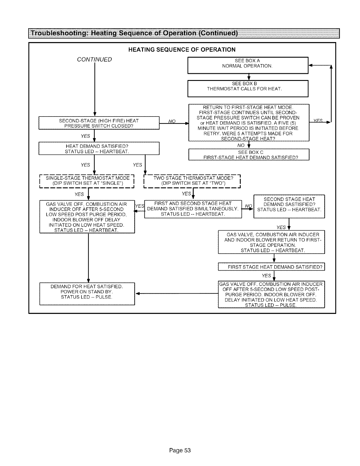
CONTINUED
HEATING SEQUENCE OF OPERATION
SEE BOX A
NORMAL OPERATION.
SEE BOX B
THERMOSTAT CALLS FOR HEAT.
I
[
L
I
SECOND-STAGE (HIGH FIRE) HEAT
PRESSURE SWITCH CLOSED?
YES _
HEAT DEMAND SATISFIED?
STATUS LED -- HEARTBEAT.
YES
SINGLE-STAGE THERMOSTAT MODE
(DIP SWITCH SET AT "SINGLE")
YES I
GAS VALVE OFF, COMBUSTION AIR
INDUCER OFF AFTER 5-SECOND
LOW SPEED POST PURGE PERIOD,
INDOOR BLOWER OFF DELAY
INITIATED ON LOW HEAT SPEED.
STATUS LED -- HEARTBEAT.
DEMAND FOR HEAT SATISFIED.
POWER ON STAND BY.
STATUS LED -- PULSE.
1
1I '
I I
J L
I
I
NO
I
RETURN TO FIRST-STAGE HEAT MODE.
FIRST-STAGE CONTINUES UNTIL SECOND-
STAGE PRESSURE SWITCH CAN BE PROVEN
or HEAT DEMAND IS SATISFIED. A FIVE (5)
MINUTE WAIT PERIOD IS INITIATED BEFORE
RETRY. WERE 5 ATTEMPTS MADE FOR
SECOND-STIAGE HEAT?
NO '_
SEE BOX C
FIRST-STAGE HEAT DEMAND SATISFIED? I
TWO STAGE THERMOSTAT MODE? 1,
(DIP SWITCH SET AT "TWO") I
J
YES'f
I, _[ FIRST AND SECOND STAGE HEAT I,,_ DEMANDSECONDSASTISFIED?STAGEHEAT
IY/-_b
_,_J DEMAND SATISFIED SIMULTANEOUSLY. FSTATUS LED -- HEARTBEAT.
I- I STATUS LED -- HEARTBEAT. YES
I GAS VALVE, COMBUSTION AIR INDUCER
AND INDOOR BLOWER RETURN TO FIRST-
STAGE OPERATION.
STATUS LED -- HEARTBEAT.
I FIRST STAGE HEAT DEMAND SATISFIED? I
YES
4 GAS VALVE OFF. COMBUSTION AIR INDUCER
OFF AFTER 5-SECOND LOW SPEED POST-
PURGE PERIOD. INDOOR BLOWER OFF.
DELAY INITIATED ON LOW HEAT SPEED.
STATUS LED -- PULSE.
Page 53
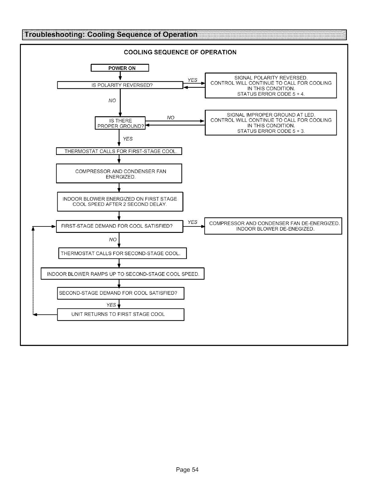
COOLINGSEQUENCEOF OPERATION
I
I
I POWER ON I
IS POLARITY REVERSED?
I IS THERE NO
PROPER GROUND? 9
_YES
THERMOSTAT CALLS FOR FIRST-STAGE COOL. I
4,
COMPRESSOR AND CONDENSER FAN
ENERGIZED.
4,
INDOOR BLOWER ENERGIZED ON FIRST STAGE
COOL SPEED AFTER 2 SECOND DELAY,
SIGNAL POLARITY REVERSED.
CONTROL WILL CONTINUE TO CALL FOR COOLING
IN THIS CONDITION,
STATUS ERROR CODE 5 + 4.
SIGNAL IMPROPER GROUND AT LED.
CONTROL WILL CONTINUE TO CALL FOR COOLING
IN THIS CONDITION,
STATUS ERROR CODE 5 + 3.
I_ COMPRESSOR AND CONDENSER FAN DE-ENERGIZED.
FIRST-STAGE DEMAND FOR COOL SATISFIED? NDOOR BLOWER DE-ENEG ZED.
Nol
ITHERMOSTATOALLSFORSEOOND-STAGECOOL.I
I ,NDOORBLOWERRAMPSUPTOSECOND-STAGECOOLSPEED.I
SECOND-STAGE DEMAND FOR COOL SATISFIED? I
YES
-_1 o.,_o_.s_o_,_s_s_A_COO.I
Page 54
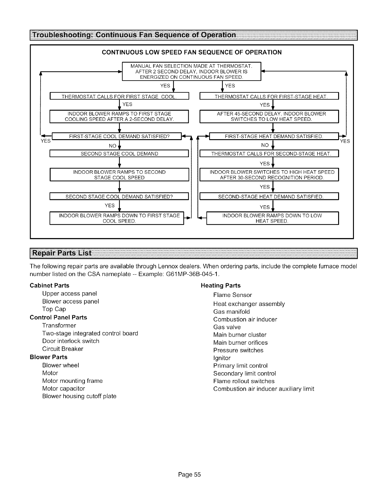
CONTINUOUSLOW SPEED FAN SEQUENCE OF OPERATION
ID
YES
I THERMOSTAT CALLS FOR FIRST STAGE COOL.
YES
I INDOOR BLOWER RAMPS TO FIRST STAGE
COOLING SPEED AFTER A 2-SECOND DELAY,
FIRST-STAGE COOL DEMAND SATISFIED?
NO_
I SECONDSTAGECOOLDEMAND I
I INDOOR BLOWER RAMPS TO SECOND
STAGE COOL SPEED
I SECONDSTAGECOOLDEMANDSAT,SFED?I
YES
I 'NDOORBLOWERRAMPSDOWNTOF'RSTSTAGEI_cooLSPEED
MANUAL FAN SELECTION MADE AT THERMOSTAT.
AFTER 2 SECOND DELAY, INDOOR BLOWER IS
ENERGIZED ON CONTINUOUS FAN SPEED,
I I
II
I
I
I
ii
YES
THERMOSTAT CALLS FOR FIRST-STAGE HEAT. I
YES
AFTER 45-SECOND DELAY, INDOOR BLOWER I
SWITCHES TO LOW HEAT SPEED,
FIRST-STAGE HEAT DEMAND SATISFIED. _YI
NO
THERMOSTAT CALLS FOR SECOND-STAGE HEAT. I
YES ,_
INDOOR BLOWER SWITCHES TO HIGH HEAT SPEED I
AFTER 30-SECOND RECOGNITION PERIOD.
YES ,_
SECOND-STAGE HEAT DEMAND SATISFIED. I
YES
INDOOR BLOWERHEATRAMPSsPEED.DOWNTO LOW I
The following repair parts are available through Lennox dealers, When ordering parts, include the complete furnace model
number listed on the CSA nameplate -- Example: G61MP-36B-045-1,
Cabinet Parts
Upper access panel
Blower access panel
Top Cap
Control Panel Parts
Transformer
Two-stage integrated control board
Door interlock switch
Circuit Breaker
Blower Parts
Blower wheel
Motor
Motor mounting frame
Motor capacitor
Blower housing cutoff plate
Heating Parts
Flame Sensor
Heat exchanger assembly
Gas manifold
Combustion air inducer
Gas valve
Main burner cluster
Main burner orifices
Pressure switches
Ignitor
Primary limit control
Secondary limit control
Flame rollout switches
Combustion air inducer auxiliary limit
Page 55
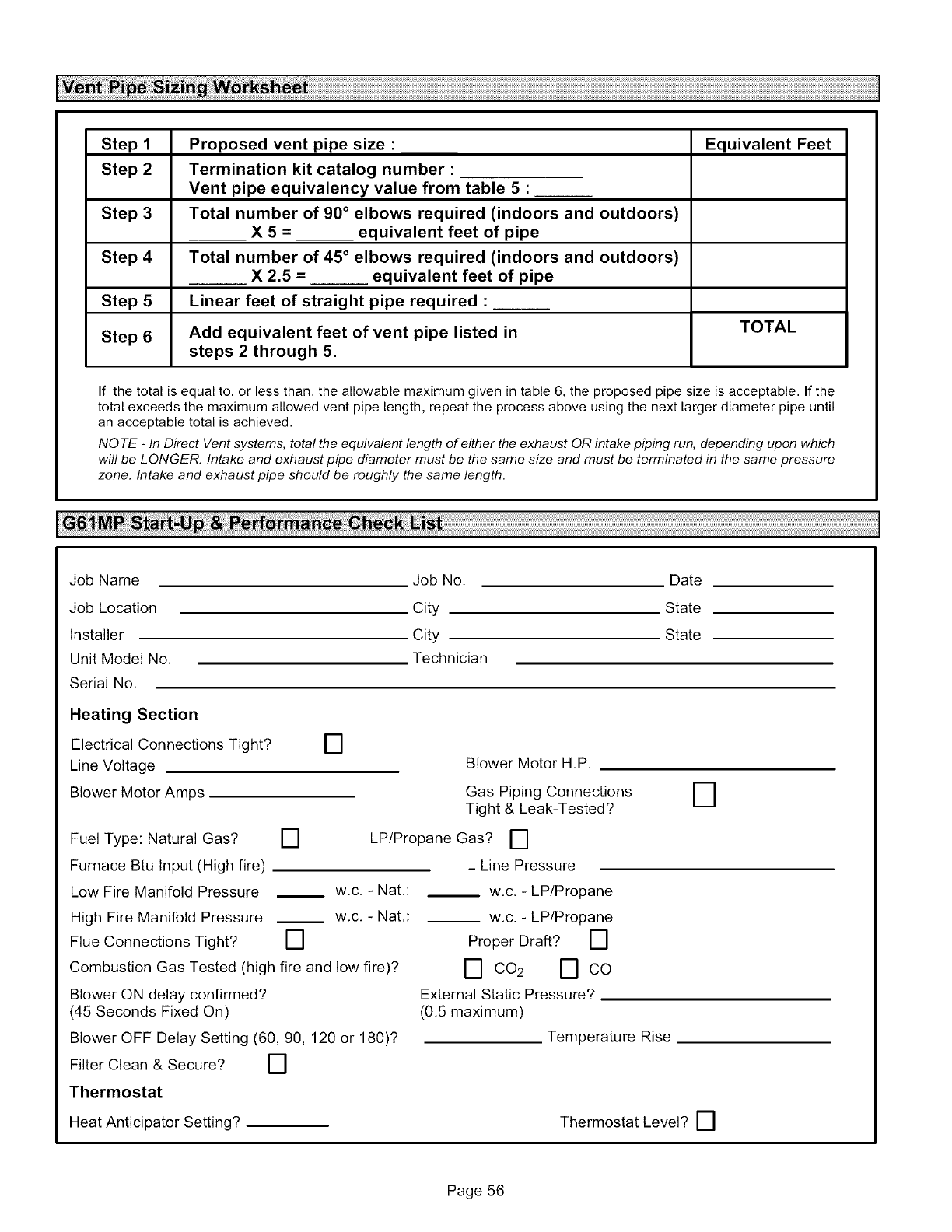
Step 1
Step 2
Step 3
Step 4
Step 5
Step 6
Proposed vent pipe size :
Termination kit catalog number :
Vent pipe equivalency value from table 5 :
Total number of 90 ° elbows required (indoors and outdoors)
X 5 = equivalent feet of pipe
Total number of 45 ° elbows required (indoors and outdoors)
X 2.5 = equivalent feet of pipe
Linear feet of straight pipe required :
Add equivalent feet of vent pipe listed in
steps 2 through 5.
Equivalent Feet
TOTAL
If the total is equal to, or less than, the allowable maximum given in table 6, the proposed pipe size is acceptable. If the
total exceeds the maximum allowed vent pipe length, repeat the process above using the next larger diameter pipe until
an acceptable total is achieved.
NOTE -In Direct Vent systems, total the equivalent length of either the exhaust OR intake piping run, depending upon which
will be LONGER. Intake and exhaust pipe diameter must be the same size and must be terminated in the same pressure
zone. Intake and exhaust pipe should be roughly the same length.
Job Name Job No. Date
Job Location City State
Installer City State
Unit Model No. Technician
Serial No.
Heating Section
Electrical Connections Tight?
Line Voltage
Blower Motor Amps
[]
Fuel Type: Natural Gas? []
Blower Motor H,P.
Gas Piping Connections
Tight & Leak-Tested?
LP/Propane Gas? []
D
Furnace Btu Input (High fire)
Low Fire Manifold Pressure
High Fire Manifold Pressure
Flue Connections Tight?
w.c, - Nat,:
w.c. -Nat,:
[]
Combustion Gas Tested (high fire and low fire)?
_ Line Pressure
w,c, - LP/Propane
__ w,c, - LP/Propane
Proper Draft? []
[] co2 [] co
Blower ON delay confirmed?
(45 Seconds Fixed On)
Blower OFF Delay Setting (60, 90, 120 or 180)?
Filter Clean & Secure? []
Thermostat
Heat Anticipator Setting?
External Static Pressure?
(0.5 maximum)
Temperature Rise
Thermostat Level? []
Page 56
