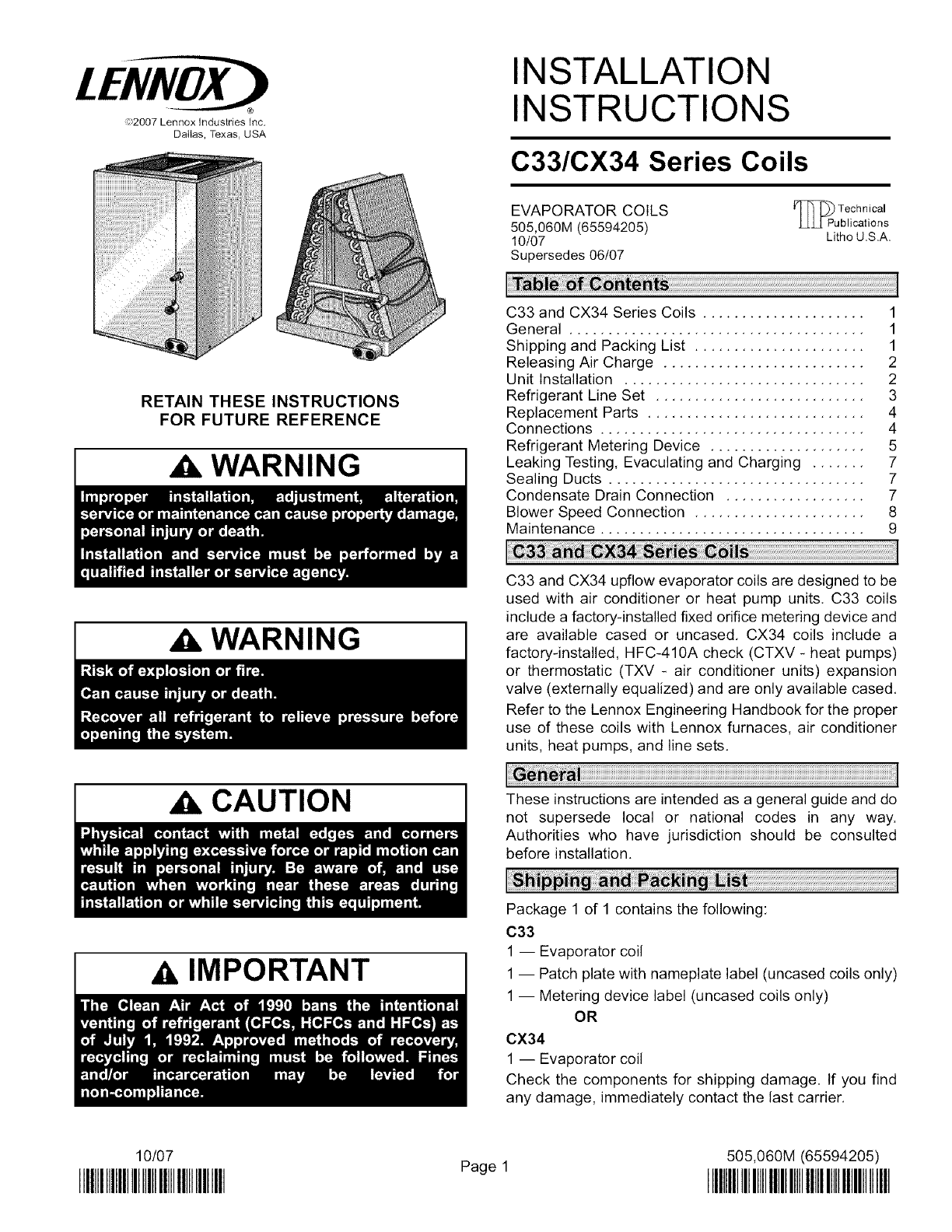
LENNOX Evaporator Coils Manual L0806270
User Manual: LENNOX LENNOX Evaporator Coils Manual LENNOX Evaporator Coils Owner's Manual, LENNOX Evaporator Coils installation guides
Open the PDF directly: View PDF ![]() .
.
Page Count: 9
®
,t_2007 Lennox Industries Inc.
DatIas, Texas, USA
RETAIN THESE INSTRUCTIONS
FOR FUTURE REFERENCE
WARNING
WARNING
CAUTION
AIMPORTANT
10/07
IIIHllllll]]lll]llllllllll]lllllllll]
INSTALLATION
INSTRUCTIONS
C33/CX34 Series Coils
EVAPORATOR COILS _ Technical
505,060M (65594205) LL.L[Publications
10/07 Litho U.S.A.
Supersedes 06/07
C33 and CX34 Series Coils ..................... 1
General ...................................... 1
Shipping and Packing List ...................... 1
Releasing Air Charge .......................... 2
Unit Installation ............................... 2
Refrigerant Line Set ........................... 3
Replacement Parts ............................ 4
Connections .................................. 4
Refrigerant Metering Device .................... 5
Leaking Testing, Evaculating and Charging ....... 7
Sealing Ducts ................................. 7
Condensate Drain Connection .................. 7
Blower Speed Connection ...................... 8
Maintenance .................................. 9
C33 and CX34 upflow evaporator coils are designed to be
used with air conditioner or heat pump units. C33 coils
include a factory-installed fixed orifice metering device and
are available cased or uncased. CX34 coils include a
factory-installed, HFC-410A check (CTXV - heat pumps)
or thermostatic (TXV - air conditioner units) expansion
valve (externally equalized) and are only available cased.
Refer to the Lennox Engineering Handbook for the proper
use of these coils with Lennox furnaces, air conditioner
units, heat pumps, and line sets.
These instructions are intended as a general guide and do
not supersede local or national codes in any way.
Authorities who have jurisdiction should be consulted
before installation.
Package 1 of 1 contains the following:
C33
1 -- Evaporator coil
1 -- Patch plate with nameplate label (uncased coils only)
1 -- Metering device label (uncased coils only)
OR
CX34
1 -- Evaporator coil
Check the components for shipping damage. If you find
any damage, immediately contact the last carrier.
Page 1 505,060M (65594205)
II]lllllllll]llllllllHlllllllllll]]lllll
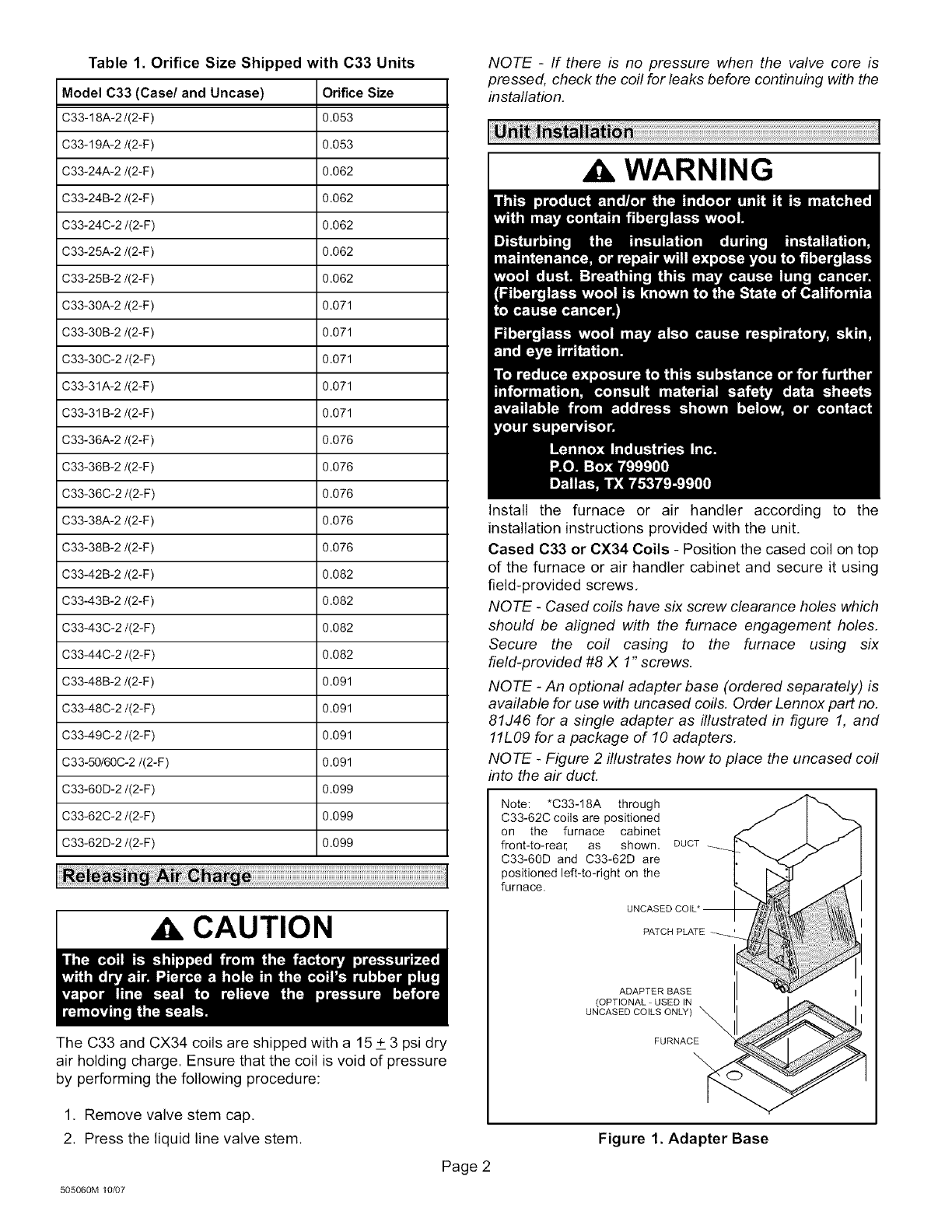
Table 1. Orifice Size Shipped with C33 Units
Model C33 (Case/and Uncase) Orifice Size
C33-18A-2/(2-F) 0.053
C33-19A-2/(2-F) 0.053
C33-24A-2/(2-F) 0.062
C33-24B-2/(2-F) 0.062
C33-24C-2/(2-F) 0.062
C33-25A-2/(2-F) 0.062
C33-25B-2/(2-F) 0.062
C33-30A-2/(2-F) 0.071
C33-30B-2/(2-F) 0.071
C33-30C-2/(2-F) 0.071
C33-31A-2/(2-F) 0.071
C33-31B-2/(2-F) 0.071
C33-36A-2/(2-F) 0.076
C33-36B-2/(2-F) 0.076
C33-36C-2/(2-F) 0.076
C33-38A-2/(2-F) 0.076
C33-38B-2/(2-F) 0.076
C33-42B-2/(2-F) 0.082
C33-43B-2/(2-F) 0.082
C33-43C-2/(2-F) 0.082
C33-44C-2/(2-F) 0.082
C33-48B-2/(2-F) 0.091
C33-48C-2/(2-F) 0.091
C33-49C-2/(2-F) 0.091
C33-50/60C-2/(2-F) 0.091
C33-60D-2/(2-F) 0.099
C33-62C-2/(2-F) 0.099
C33-62D-2/(2-F) 0.099
a CAUTION
The C33 and CX34 coils are shipped with a 15 + 3 psi dry
air holding charge. Ensure that the coil is void of pressure
by performing the following procedure:
1. Remove valve stem cap,
2. Press the liquid line valve stem.
505060M 10_7
Page 2
NOTE -If there is no pressure when the valve core is
pressed, check the coil for leaks before continuing with the
installation.
a WARNING
Install the furnace or air handler according to the
installation instructions provided with the unit.
Cased C33 or CX34 Coils - Position the cased coil on top
of the furnace or air handler cabinet and secure it using
field-provided screws,
NOTE - Cased coils have six screw clearance holes which
should be aligned with the furnace engagement holes.
Secure the coil casing to the furnace using six
field-provided #8 X 1" screws.
NOTE -An optional adapter base (ordered separately) is
available for use with uncased coils. Order Lennox part no.
81J46 for a single adapter as illustrated in figure 1, and
11L09 for a package of 10 adapters.
NOTE -Figure 2illustrates how to place the uncased coil
into the air duct.
Note: *C33-18A through
C33-62C coils are positioned
on the furnace cabinet
front-to-rear, as shown,
C33-60D and C33-62D are
positioned left-to-right on the
furnace.
DUCT
PATCH PLATE __
ADAPTER BASE
(OPTIONAL-USEDIN
UNCASED COILS ONLY)
FURNACE
\
Figure 1. Adapter Base
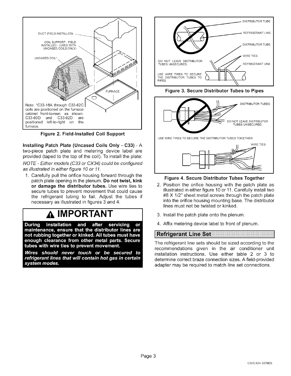
DUCT (FIELD INSTALLED)
COIL SUPPORT - FIELD
INSTALLED - (USED WITH
UNCASED COILS ONLY)
UNCASED COIL*
Note: *C33-18A through C33-62C
coils are positioned on the furnace
cabinet front-to-rear, as shown,
C33-60D and C33-62D are
positioned left-to-right on the
furnace.
Figure 2. Field-Installed Coil Support
Installing Patch Plate (Uncased Coils Only - C33) -A
two-piece patch plate and metering device label are
provided (taped to the top of the coil), To install the plate:
NOTE -Either models (C33 or CX34) could be configured
as illustrated in either figure 10 or 11,
1. Carefully pull the orifice housing forward through the
patch plate opening in the plenum. Do not twist, kink
or damage the distributor tubes. Use wire ties to
secure tubes to prevent movement that could cause
the refrigerant tubing to fail. Adjust the tubes if
necessary as illustrated in figures 3 and 4.
AIMPORTANT
PIPES.
Figure 3. Secure Distributor Tubes to Pipes
_B DISTRIBUTOR TUBES
DO NOT LEAVE DISTRIBUTOR
ES UNSECURED.
USE WIRE TIRES TO SECURE THE DISTRIBUTOR TUBES TOGETHER.
WIRE TIES
Figure 4. Secure Distributor Tubes Together
2. Position the orifice housing with the patch plate as
illustrated in either figure 10 or 11. Carefully install two
#8 X 1/2" sheet metal screws through the patch plate
into the orifice housing mounting base. The distributor
lines must not be twisted or kinked,
3. Install the patch plate onto the plenum.
4. Affix metering device label to front of plenum.
The refrigerant line sets should be sized according to the
recommendations given in the air conditioner unit
installation instructions. Use either table 2 or 3 to
determine correct braze connection sizes. A field-provided
adapter may be required to match line set connections.
Page 3
C33/CX34 SERIES
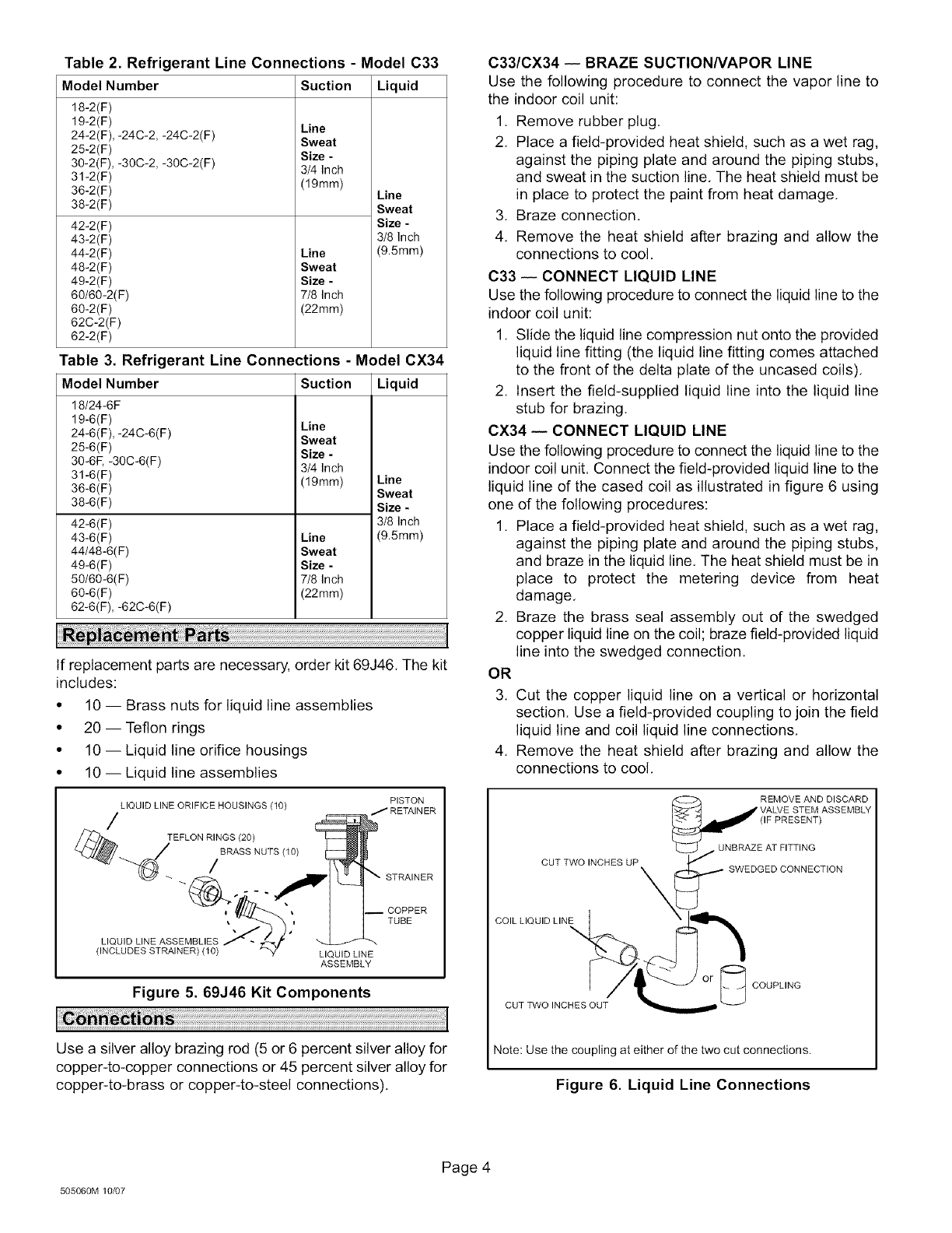
Table 2. Refrigerant Line Connections - Model C33
Model Number Suction Liquid
18-2(F)
19-2(F)
24-2(F), -24C-2, -24C-2(F)
25-2(F)
30-2(F), -30C-2, -3OC-2(F)
31-2(F)
36-2(F)
38-2(F)
42-2(F)
43-2(F)
44-2(F)
48-2(F)
49-2(F)
60/60-2(F)
60-2(F)
62C-2(F)
62-2(F)
Line
Sweat
Size -
3/4 Inch
(19mm)
Line
Sweat
Size -
7/8 Inch
(22mm)
Line
Sweat
Size -
3/8 Inch
(9.5mm)
Table 3. Refrigerant Line Connections - Model CX34
Model Number Suction Liquid
18/24-6F
19-6(F)
24-6(F), -24C-6(F)
25-6(F)
30-6E -3OC-6(F)
31-6(F)
36-6(F)
38-6(F)
42-6(F)
43-6(F)
44/48-6(F)
49-6(F)
50/60-6(F)
60-6(F)
62-6(F), -62C-6(F)
Line
Sweat
Size -
3/4 Inch
(1gram)
Line
Sweat
Size -
7/8 Inch
(22ram)
Line
Sweat
Size -
3/8 Inch
(9.5mm)
If replacement parts are necessary, order kit 69J46. The kit
includes:
• 10 -- Brass nuts for liquid line assemblies
• 20 -- Teflon rings
• 10 -- Liquid line orifice housings
• 10 -- Liquid line assemblies
PISTON
LIQUID LINE ORIFICE HOUSINGS (10) J RETAINER
/TEFLON RINGS (20)
//BRASS NUTS (I 0)
"_ E] L_ _" STRAINER
] ]--O%ER
L,QU,DUNEASSEMSL,ES
(INCLUDES STRAINER) (10) LIQUID LINE
ASSEMBLY
Figure 5.69J46 Kit Components
Use a silver alloy brazing rod (5 or 6 percent silver alloy for
copper-to-copper connections or 45 percent silver alloy for
copper4o-brass or copper-to-steel connections).
C33/CX34 -- BRAZE SUCTIONNAPOR LINE
Use the following procedure to connect the vapor line to
the indoor coil unit:
1. Remove rubber plug.
2. Place a field-provided heat shield, such as a wet rag,
against the piping plate and around the piping stubs,
and sweat in the suction line. The heat shield must be
in place to protect the paint from heat damage.
3. Braze connection.
4. Remove the heat shield after brazing and allow the
connections to cool.
C33 -- CONNECT LIQUID LINE
Use the following procedure to connect the liquid line to the
indoor coil unit:
1. Slide the liquid line compression nut onto the provided
liquid line fitting (the liquid line fitting comes attached
to the front of the delta plate of the uncased coils).
2. Insert the field-supplied liquid line into the liquid line
stub for brazing.
CX34 -- CONNECT LIQUID LINE
Use the following procedure to connect the liquid line to the
indoor coil unit. Connect the field-provided liquid line to the
liquid line of the cased coil as illustrated in figure 6 using
one of the following procedures:
1. Place a field-provided heat shield, such as a wet rag,
against the piping plate and around the piping stubs,
and braze in the liquid line. The heat shield must be in
place to protect the metering device from heat
damage.
2. Braze the brass seal assembly out of the swedged
copper liquid line on the coil; braze field-provided liquid
line into the swedged connection.
OR
3. Cut the copper liquid line on a vertical or horizontal
section. Use a field-provided coupling to join the field
liquid line and coil liquid line connections.
4. Remove the heat shield after brazing and allow the
connections to cool.
REMOVE AND DISCARD
STEM ASSEMBLY
(IF PRESENT)
CUT TWO INCHES UP \
COIL LIQUID LINE
\
UNBRAZE AT FITTING
SWEDGED CONNECTION
CUT TWO INCHES OUT
COUPLING
Note: Use the coupling at either of the two cut connections.
Figure 6. Liquid Line Connections
505060M 10/07
Page 4
Beloware the factory-installedmeteringdevicesand
optionalmeteringdevicesif applicableto bothtypesof
coils.
• TheC33coilsareshippedwithafactory-installedfixed
orifice.C33casedanduncasedcoilsarecompatible
with eitherHFC-410Afixed orificeor TXV/CTXV
meteringdevices,
• CX34casedcoilshavefactory-installedHFC-410A
TXV/CTXVmeteringdevices,
ThepreviouslyreferenceTXV/CTXVmeteringdeviceswill
bereferredto inthisinstructionasTXV,
DETERMININGCORRECTFIXEDORIFICE
A properlysizedfixedorificemaybe providedwiththe
outdoorunit.Refertotheoutdoorunitinstructiontoensure
propersizingof the refrigerantflow controlorifice.An
improperlysized RFCorificecan lead to diminished
capacitiesand/orefficiencies,aswellaspotentialdamage
totheunit,RFCsshippedwiththecoilsareidentifiedin
table1.
I_I/8 TURN
I/2TURN
Figure 7. Tightening Distance
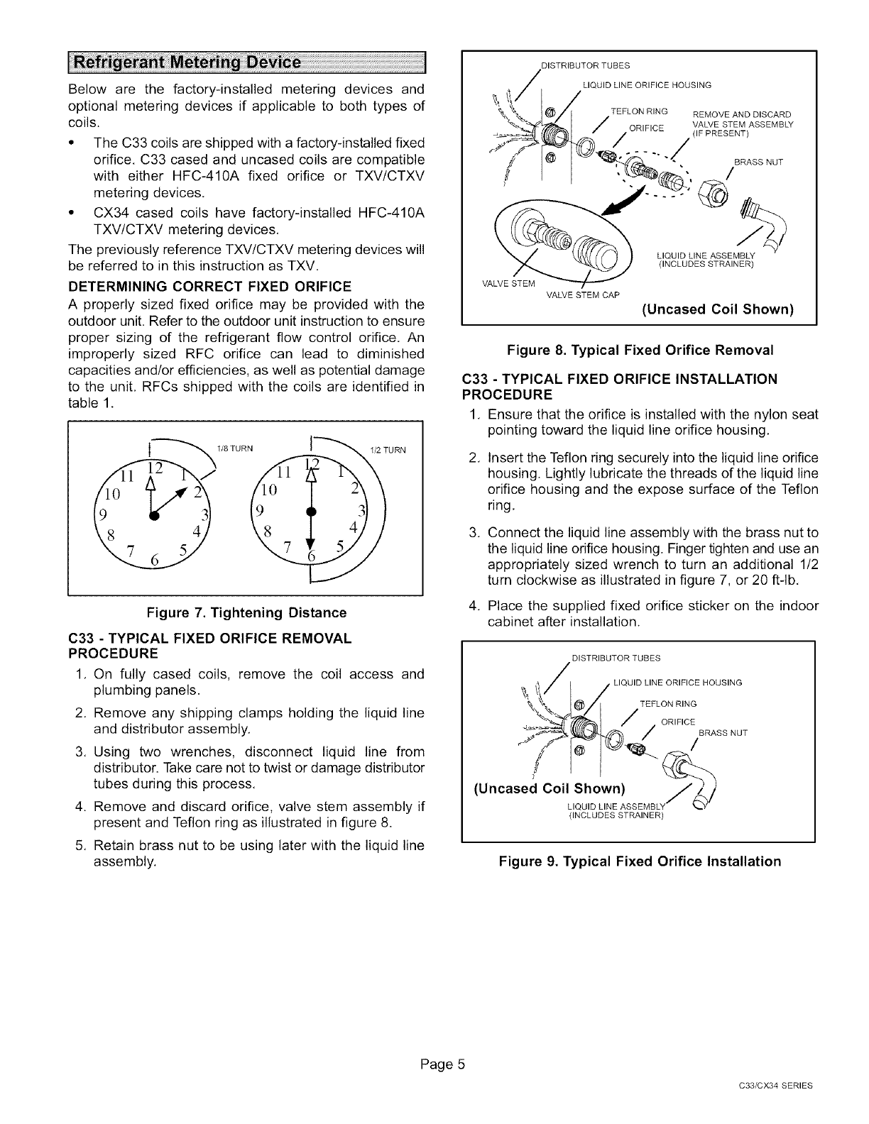
C33 - TYPICAL FIXED ORIFICE REMOVAL
PROCEDURE
1. On fully cased coils, remove the coil access and
plumbing panels.
2. Remove any shipping clamps holding the liquid line
and distributor assembly,
3. Using two wrenches, disconnect liquid line from
distributor. Take care not to twist or damage distributor
tubes during this process,
4. Remove and discard orifice, valve stem assembly if
present and Teflon ring as illustrated in figure 8.
5. Retain brass nut to be using later with the liquid line
assembly.
DISTRIBUTOR TUBES
LIQUID LINE ORIFICE HOUSING
TEFLON RING REMOVE AND DISCARD
ORIFICE VALVE STEM ASSEMBLY
(IF PRESENT)
#
BRASS NUT
/
VALVE STEM
VALVE STEM CAP
LIQUID LINE ASSEMBLY
(INCLUDES STRAINER)
(Uncased Coil Shown)
Figure 8. Typical Fixed Orifice Removal
C33 - TYPICAL FIXED ORIFICE INSTALLATION
PROCEDURE
1, Ensure that the orifice is installed with the nylon seat
pointing toward the liquid line orifice housing,
,Insert the Teflon ring securely into the liquid line orifice
housing. Lightly lubricate the threads of the liquid line
orifice housing and the expose surface of the Teflon
ring,
,Connect the liquid line assembly with the brass nut to
the liquid line orifice housing. Finger tighten and use an
appropriately sized wrench to turn an additional 1/2
turn clockwise as illustrated in figure 7, or 20 ftqb,
4. Place the supplied fixed orifice sticker on the indoor
cabinet after installation.
Figure 9. Typical Fixed Orifice Installation
Page 5
C33/CX34 SERIES
C33 - TYPICAL TXV INSTALLATION PROCEDURE
The TXV unit can be installed internal or external to the
indoor coil. In applications where an uncased coil is being
installed in a field-provided plenum, install the TXV in a
manner that will provide access for field servicing of the
TXV. Refer to figures 10 or 11 for reference during
installation of TXV unit.
(Uncased Coil Shown)
TWO PIECE
PATCH PLATE LIQUID LINE
UNCASED COIL ORIFICE STUB END
ONLY) HOUSING
DISTRIBUTOR TXV
TUBES
RING
SENSING
LINE
MALE EQUALIZER LINE
FITTING (SEE FIGURE
13 FOR FURTHER
DETAILS)
Sensing bulb insulation is
required if mounted external to
the coil casing. See figure 12 for
bulb positioning.
LIQUID
LINE
Figure 10. Patch Plate (Configuration A)
(uncased coil shown)
MALE EQUALIZER LINE
FITTING (SEE FIGURE
13 FOR FURTHER
DISTRIBUTOR
TUBES
,PIECE PATCH PLATE
Sensing bulb insulation is
required if mounted external
VAPOR LINE to the coil casing. See figure
f 12 for bulb positioning,
S_BNuSIBN _ "UB END
SENSING
TXVTEFLON
RING
TEFLON
RING
LIQUID LINE
ORIFICE
HOUSING
LIQUID LINE ASSEMBLh
WITH BRASS NUT
Figure 11. Patch Plate (Configuration B)
1, Insert one of the provided Teflon rings into the stubbed
end of the TXV, Lightly lubricate the threads of the
stubbed end of the TXV and the expose surface of the
Teflon ring.
2, Attach the stubbed end of the TXV to the liquid line
orifice housing, Finger tighten and use an appropriately
sized wrench to turn an additional 1/2 turn clockwise
as illustrated in figure 7, or 20 ft-lb,
3, Place the remaining Teflon washer around the other
end of the TXV and lightly lubricate the threads of the
that end of the TXV, and the expose surface of the
Teflon ring,
4, Attach the liquid line assembly with brass nut to the
TXV. Finger tighten and use an appropriately sized
wrench to turn an additional 1/2 turn clockwise as
illustrated in figure 7, or 20 ft-lb,
5, Attach the sensing bulb of the TXV in the proper
orientation as illustrated in figure 12 to the suction line
using the clamp and screws provided.
On lines smaller than
Suction Line .. 7/8", mount sensing bulb
at either the 3 or 9 o'clock
(Bu,b Bu,b)
On 7/8" and larger lines,
Suction Line _ mount sensing bulb at
_.___ _.,/_/either the 4 or 8 o'clock
• _. position, never mount on
,_, , \\ bottom of line.
O" I "_\\_q I
NOTE -Never mount on bottom of line.
Figure 12. TXV Sensing Bulb Installation
NOTE -To prevent any possibility of water damage,
properly insulate all parts of the TXV assembly that may
sweat due to temperature differences between the valve
and its surrounding ambient temperatures.
6. Connect the equalizer line from the TXV to the
equalizer suction port on the suction line. Finger
tighten the flare nut plus 1/8 turn (7 ft-lbs) as illustrated
in figure 7.
XkIMPORTANT
505060M 10/07
Page 6
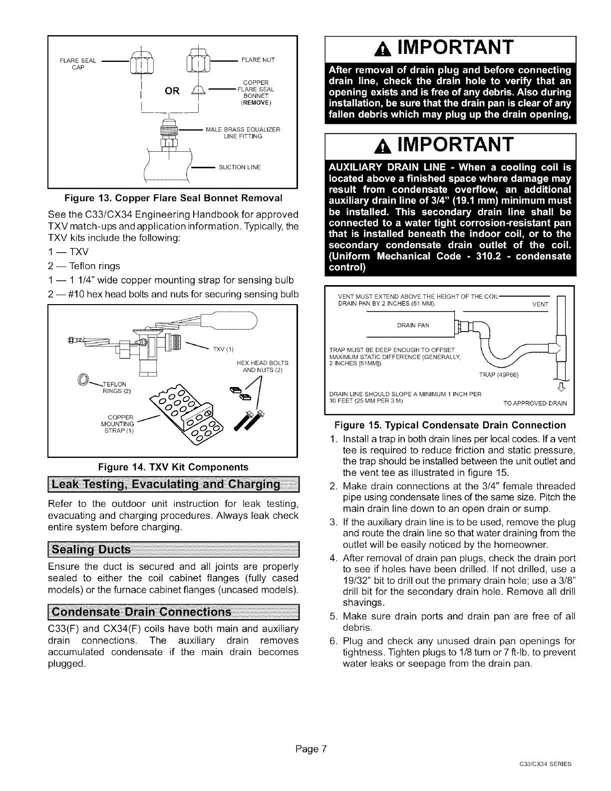
FLAREcApSEAL _._ _FLARE NUT
,_ COPPER
OR --FLARE SEAL
BONNET
I (REMOVE)
I
-- MALE BRASS EQUALIZER
_ LINE FITTING
SUCTION LINE
Figure 13. Copper Flare Seal Bonnet Removal
See the C33/CX34 Engineering Handbook for approved
TXV match-ups and application information, Typically, the
TXV kits include the following:
1 -- TXV
2 -- Teflon rings
1 -- 1 1/4" wide copper mounting strap for sensing bulb
2 -- #10 hex head bolts and nuts for securing sensing bulb
%1%51(°?s
@ TEFLON
RINGS (2)
COPPER
MOUNTING
STRAP (I)
Figure 14. TXV Kit Components
Refer to the outdoor unit instruction for leak testing,
evacuating and charging procedures, Always leak check
entire system before charging,
Ensure the duct is secured and all joints are properly
sealed to either the coil cabinet flanges (fully cased
models) or the furnace cabinet flanges (uncased models),
C33(F) and CX34(F) coils have both main and auxiliary
drain connections, The auxiliary drain removes
accumulated condensate if the main drain becomes
plugged,
AIMPORTANT
AIMPORTANT
VENT MUST EXTEND ABOVE THE HEIGHT OF THE COIL"
DRAIN PAN BY 2 INCHES (51 MM). VENT
DRAIN PAN
TRAP MUST BE DEEP ENOUGH TO OFFSET
MAXIMUM STATIC DIFFERENCE (GENERAL
2 INCHES [51MM]).
TRAP (49P66)
DRAIN LINE SHOULD SLOPE A MINIMUM 1 INCH PER
10 FEET (25 MM PER 3 M) TO APPROVED DRAIN
Figure 15. Typical Condensate Drain Connection
1, Install a trap in both drain lines per local codes, Ifa vent
tee is required to reduce friction and static pressure,
the trap should be installed between the unit outlet and
the vent tee as illustrated in figure 15,
2, Make drain connections at the 3/4" female threaded
pipe using condensate lines dthe same size. Pitch the
main drain line down to an open drain or sump.
3, If the auxiliary drain line is to be used, remove the plug
and route the drain line so that water draining from the
outlet will be easily noticed by the homeowner.
4, After removal of drain pan plugs, check the drain port
to see if holes have been drilled. If not drilled, use a
19/32" bit to drill out the primary drain hole; use a 3/8"
drill bit for the secondary drain hole, Remove all drill
shavings.
5, Make sure drain ports and drain pan are free of all
debris.
6, Plug and check any unused drain pan openings for
tightness. Tighten plugs to 1/8 tum or 7 ft-lb, to prevent
water leaks or seepage from the drain pan,
Page 7
C33/CX34 SERIES
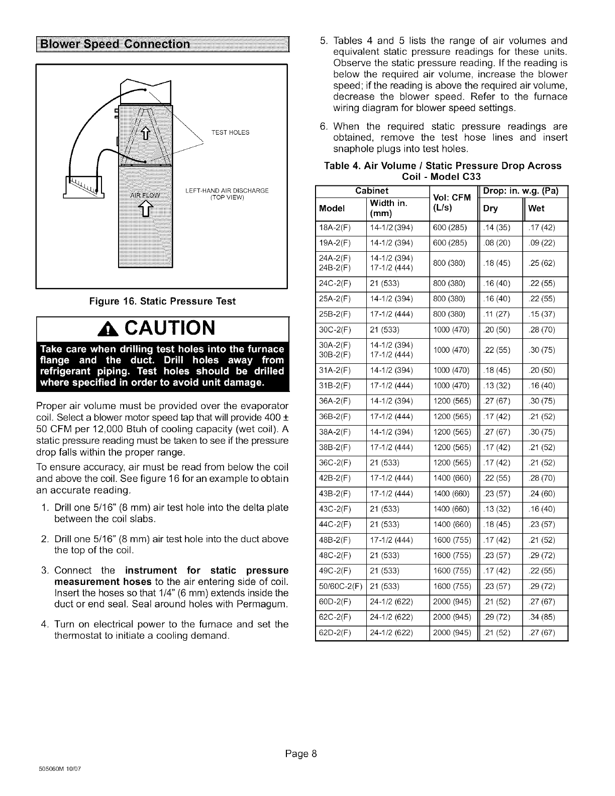
TESTHOLES
LEFT-HANDAIRDISCHARGE
(TOPVlEW)
Figure 16. Static Pressure Test
CAUTION
Proper air volume must be provided over the evaporator
coil. Select a blower motor speed tap that will provide 400 _+
50 CFM per 12,000 Btuh of cooling capacity (wet coil). A
static pressure reading must be taken to see if the pressure
drop falls within the proper range,
To ensure accuracy, air must be read from below the coil
and above the coil. See figure 16 for an example to obtain
an accurate reading,
1. Drill one 5/16" (8 mm) air test hole into the delta plate
between the coil slabs,
2. Drill one 5/16" (8 mm) air test hole into the duct above
the top of the coil,
3. Connect the instrument for static pressure
measurement hoses to the air entering side of coil.
Insert the hoses so that 1/4" (6 mm) extends inside the
duct or end seal, Seal around holes with Permagum,
4. Turn on electrical power to the furnace and set the
thermostat to initiate a cooling demand.
5. Tables 4 and 5 lists the range of air volumes and
equivalent static pressure readings for these units.
Observe the static pressure reading. If the reading is
below the required air volume, increase the blower
speed; if the reading is above the required air volume,
decrease the blower speed. Refer to the furnace
wiring diagram for blower speed settings,
6. When the required static pressure readings are
obtained, remove the test hose lines and insert
snaphole plugs into test holes,
Table 4. Air Volume /Static Pressure Drop Across
Coil - Model C33
Cabinet Drop:
Voh CFM
Model
18A-2(F)
19A-2(F)
24A-2(F)
24B-2(F)
24C-2(F)
25A-2(F)
25B-2(F)
30C-2(F)
30A-2(F)
30B-2(F)
31A-2(F)
31B-2(F)
36A-2(F)
36B-2(F)
38A-2(F)
38B-2(F)
36C-2(F)
42B-2(F)
43B-2(F)
43C-2(F)
44C-2(F)
48B-2(F)
48C-2(F)
49C-2(F)
50/60C-2(F)
60D-2(F)
62C-2(F)
62D-2(F)
Width in.
(ram)
14-1/2 (394)
14-1/2 (394)
14-1/2 (394)
17-1/2 (444)
21 (533)
14-1/2 (394)
17-1/2 (444)
21 (533)
14-1/2 (394)
17-1/2 (444)
14-1/2 (394)
17-1/2 (444)
14-1/2 (394)
17-1/2 (444)
14-1/2 (394)
17-1/2 (444)
21 (533)
17-1/2 (444)
17-1/2 (444)
21 (533)
21 (533)
17-1/2 (444)
21 (533)
21 (533)
21 (533)
24-1/2 (622)
24-1/2 (622)
24-1/2 (622)
(L/s) Dry
600 (285) .14 (35)
6OO (285) .O8 (2O)
8O0 (38O) .18 (45)
800 (380) .16 (40)
800 (380) .16 (40)
800 (380) .11 (27)
1000 (470) .20 (50)
1000 (470) .22 (55)
1000 (470) .18 (45)
1000 (470) .13 (32)
1200 (565) .27 (67)
1200 (565) .17 (42)
1200 (565) .27 (67)
1200 (565) .17 (42)
1200 (565) .17 (42)
1400 (660) .22 (55)
1400 (660) .23 (57)
1400 (660) .13 (32)
1400 (660) .18 (45)
1600 (755) .17 (42)
1600 (755) .23 (57)
1600 (755) .17 (42)
1600 (755) .23 (57)
2000 (945) .21 (52)
2000 (945) .29 (72)
2000 (945) .21 (52)
in. w.g. (Pa)
Wet
.17 (42)
.09 (22)
.25 (62)
.22 (55)
.22 (55)
.15 (37)
.28 (70)
.3O(75)
.2O(50)
.16 (40)
.3O(75)
.21 (52)
.3O(75)
.21 (52)
.21 (52)
.28 (70)
.24 (60)
.16 (40)
.23 (57)
.21 (52)
.29 (72)
.22 (55)
.29 (72)
.27 (67)
.34 (85)
.27 (67)
505060M 10/07
Page 8
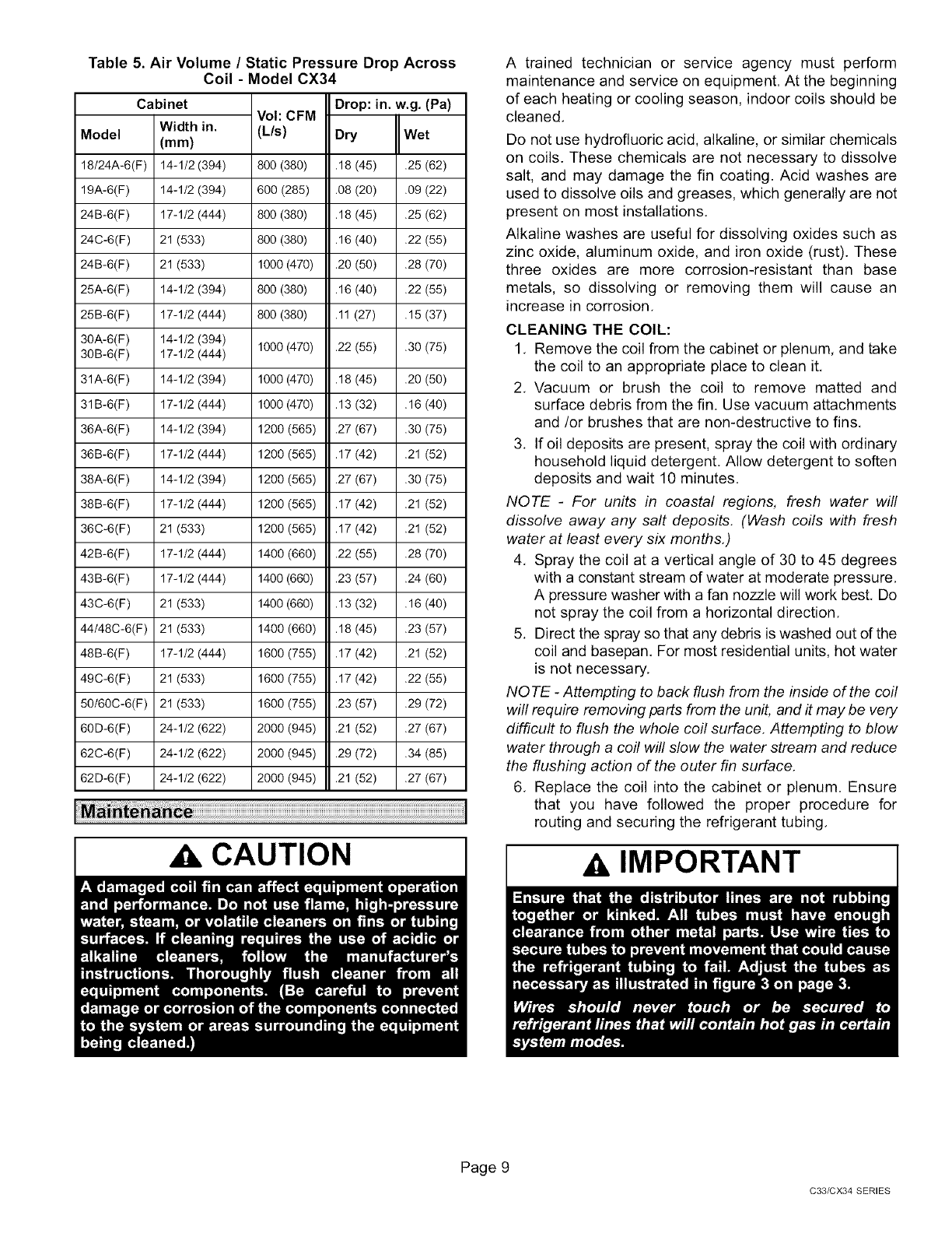
Table 5. Air Volume /Static Pressure Drop Across
Coil - Model CX34
Model
Vol: CFM
(L/s)
Cabinet
Width in.
(mm)
14-1/2 (394)
14-1/2 (394)
17-1/2 (444)
21 (533)
21 (533)
14-1/2 (394)
17-1/2 (444)
14-1/2 (394)
17-1/2 (444)
14-1/2 (394)
17-1/2 (444)
14-1/2 (394)
17-1/2 (444)
14-1/2 (394)
17-1/2 (444)
21 (533)
17-1/2 (444)
17-1/2 (444)
21 (533)
21 (533)
17-1/2 (444)
21 (533)
21 (533)
24-1/2 (622)
24-1/2 (622)
24-1/2 (622)
18/24A-6(F) 800 (380) .25 (62)
19A-6(F) 600 (285) .09 (22)
24B-6(F) 800 (380) .25 (62)
24C-6(F) 800 (380) .22 (55)
24B-6(F) 1000 (470) .28 (70)
25A-6(F) 800 (380) .22 (55)
25B-6(F) 800 (380) .15 (37)
30A-6(F)
30B-6(F) 1000 (470) .30 (75)
31A-6(F) 1000 (470) .20 (50)
31B-6(F) 1000 (470) .16 (40)
36A-6(F) 1200 (565) .30 (75)
36B-6(F) 1200 (565) .21 (52)
38A-6(F) 1200 (565) .30 (75)
38B-6(F) 1200 (565) .21 (52)
36C-6(F) 1200 (565) .21 (52)
42B-6(F) 1400 (660) .28 (70)
43B-6(F) 1400 (660) .24 (60)
43C-6(F) 1400 (660) .16 (40)
44/48C-6(F) 1400 (660) .23 (57)
48B-6(F) 1600 (755) .21 (52)
49C-6(F) 1600 (755) .22 (55)
50/60C-6(F) 1600 (755) .29 (72)
60D-6(F) 2000 (945) .27 (67)
62C-6(F) 2000 (945) .34 (85)
62D-6(F) 2000 (945) .27 (67)
Drop: in. w.g. (Pa)
Dry Wet
.18 (45)
.O8 (2O)
.18 (45)
.16 (40)
.2O (5O)
.16 (40)
.11 (27)
.22 (55)
.18 (45)
.13 (32)
.27 (67)
.17 (42)
.27 (67)
.17 (42)
.17 (42)
.22 (55)
.23 (57)
.13 (32)
.18 (45)
.17 (42)
.17 (42)
.23 (57)
.21 (52)
.29 (72)
.21 (52)
Xk CAUTION
A trained technician or service agency must perform
maintenance and service on equipment. At the beginning
of each heating or cooling season, indoor coils should be
cleaned.
Do not use hydrofluoric acid, alkaline, or similar chemicals
on coils. These chemicals are not necessary to dissolve
salt, and may damage the fin coating. Acid washes are
used to dissolve oils and greases, which generally are not
present on most installations.
Alkaline washes are useful for dissolving oxides such as
zinc oxide, aluminum oxide, and iron oxide (rust). These
three oxides are more corrosion-resistant than base
metals, so dissolving or removing them will cause an
increase in corrosion.
CLEANING THE COIL:
1. Remove the coil from the cabinet or plenum, and take
the coil to an appropriate place to clean it.
2. Vacuum or brush the coil to remove matted and
surface debris from the fin. Use vacuum attachments
and/or brushes that are non-destructive to fins.
3. If oil deposits are present, spray the coil with ordinary
household liquid detergent. Allow detergent to soften
deposits and wait 10 minutes.
NOTE -For units in coastal regions, fresh water will
dissolve away any salt deposits. (Wash coils with fresh
water at least every six months.)
4. Spray the coil at a vertical angle of 30 to 45 degrees
with a constant stream of water at moderate pressure.
A pressure washer with a fan nozzle will work best. Do
not spray the coil from a horizontal direction.
5. Direct the spray so that any debris is washed out of the
coil and basepan. For most residential units, hot water
is not necessary.
NOTE -Attempting to back flush from the inside of the coil
will require removing parts from the unit, and it may be very
difficult to flush the whole coil surface. Attempting to blow
water through a coil will slow the water stream and reduce
the flushing action of the outer fin surface.
6. Replace the coil into the cabinet or plenum. Ensure
that you have followed the proper procedure for
routing and securing the refrigerant tubing.
AIMPORTANT
Page 9
C33/CX34 SERIES
