LENNOX Evaporator Coils Manual L0806272
User Manual: LENNOX LENNOX Evaporator Coils Manual LENNOX Evaporator Coils Owner's Manual, LENNOX Evaporator Coils installation guides
Open the PDF directly: View PDF ![]() .
.
Page Count: 5

LEMV
,1,_,2008Lennox Industries Inc.
Dallas, Texas, USA
J
J
d) I
/
RETAIN THESE INSTRUCTIONS
FOR FUTURE USE
The Lennox CH23 series horizontal coils are designed for
installation with a horizontal furnace and a matched remote
outdoor unit. These units are for indoor installation only.
Refer to the Lennox engineering handbook for match-up
information.
These instructions are intended as a general guide and do
not supersede local or national codes in any way. Authori-
ties having jurisdiction should be consulted before installa-
tion.
Check contents for shipping damage. If any damage is
found, contact the last carrier immediately.
WARNING
INSTALLATION
INSTRUCTIONS
CH23 Series Coils
HORIZONTAL EVAPORATOR COILS
503,486M
04/08
Supersedes 03/00 _pu Technical
blications
CH23 Series Coil ............................... 1
General ....................................... 1
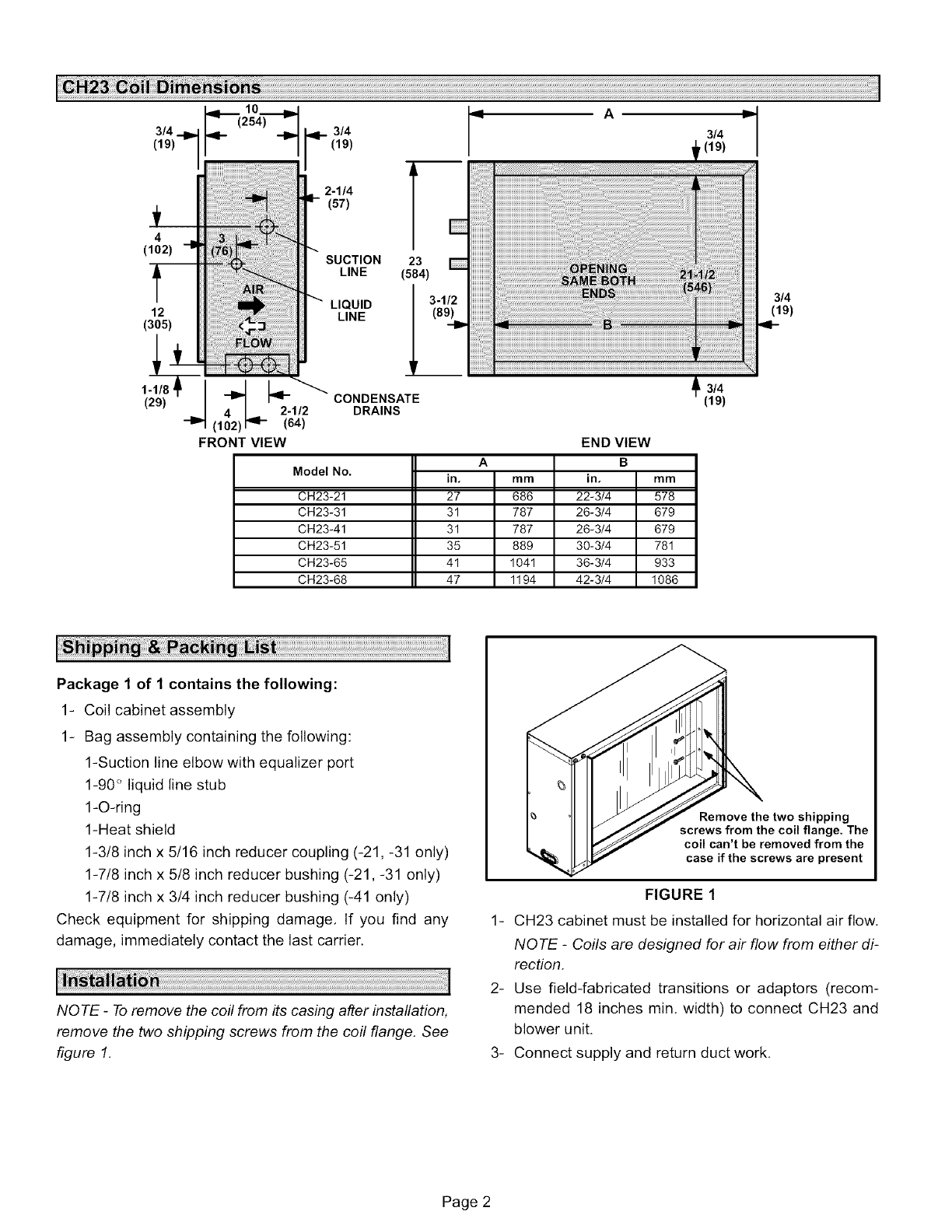
CH23 Coil Dimensions .......................... 2
Shipping & Packing List ......................... 2
Installation .................................... 2
CH23 Refrigeration Systems ..................... 3
Refrigerant Line Connections .................... 3
Condensate Drain Connections .................. 4
Evaporator Coil Air Pressure Drop ................ 4
Clean-Up ...................................... 5
AIMPORTANT
WARNING
Page 1
4
(102)
't
12
(305)
1-1/8
(29) 4-1_ _2.1/2
(102) rq- (64)
FRONT VIEW
3/4
2-1/4
(57)
SUCTION
LINE
LIQUID
LINE
23 E
(584)
_ (89)_D3"1/2
iiiiiiiiiiiii_i
iiiiiiiiiiiii_i
iiiiiiiiiiiii_i
iiiiiiiiiiiii_i
iiiiiiiiiiiii_i
iiiiiiiiiiiii_i
iiiiiiiiiiiii_i
iiiiiiiiiiiii_i
iiiiiiiiiiiii_i
iiiiiiiiiiiii_i
iiiiiiiiiiiii_i
iiiiiiiiiiiii_i
iiiiiiiiiiiii_i
iiiiiiiiiiiii_i
HHHHHH_
iiii
CONDENSATE
DRAINS
Model No.
CH23-21
CH23-31
CH23-41
CH23-51
CH23-65
CH23-68
END VIEW
A B
in. mm in. mm
27 686 22-3/4 578
31 787 26-3/4 679
31 787 26-3/4 679
35 889 30-3/4 781
41 1041 36-3/4 933
47 1194 42-3/4 1086
3/4 IP
,(19)
3/4
(19)
Package 1 of 1 contains the following:
1- Coil cabinet assembly
1- Bag assembly containing the following:
1-Suction line elbow with equalizer port
1-90 <_liquid line stub
1-O-ring
1-Heat shield
1-3/8 inch x 5/16 inch reducer coupling (-21, -31 only)
1-7/8 inch x 5/8 inch reducer bushing (-21, -31 only)
1-7/8 inch x 3/4 inch reducer bushing (-41 only)
Check equipment for shipping damage. If you find any
damage, immediately contact the last carrier.
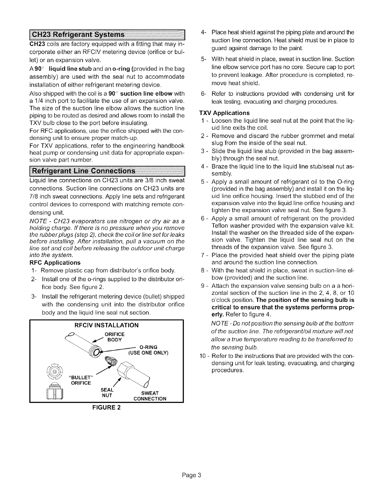
NOTE -To remove the coil from its casing after installation,
remove the two shipping screws from the coil flange. See
figure 1.
Remove the two shipping
screws from the coil flange. The
coil can't be removed from the
case if the screws are present
FIGURE 1
1- CH23 cabinet must be installed for horizontal air flow.
NOTE -Coils are designed for air flow from either di-
rection.
2- Use field-fabricated transitions or adaptors (recom-
mended 18 inches min. width) to connect CH23 and
blower unit.
3- Connect supply and return duct work.
Page 2
CH23coilsarefactoryequippedwithafittingthatmayin-
corporateeitheran RFCIVmeteringdevice(orificeorbul-
let)oranexpansionvalve.
A90<_liquidlinestubandano-ring(providedinthebag
assembly)areusedwith thesealnutto accommodate
installationofeitherrefrigerantmeteringdevice.
Alsoshippedwiththecoilisa90° suctionlineelbowwith
a 1/4inchporttofacilitatetheuseofanexpansionvalve.
Thesizeof thesuctionlineelbowallowsthesuctionline
pipingtoberoutedasdesiredandallowsroomtoinstallthe
TXVbulbcloseto theportbeforeinsulating.
ForRFCapplications,usetheorificeshippedwiththecon-
densingunitto ensurepropermatch-up.
ForTXVapplications,referto theengineeringhandbook
heatpumporcondensingunitdataforappropriateexpan-
sionvalvepartnumber.
LiquidlineconnectionsonCH23unitsare3/8inchsweat
connections.Suctionlineconnectionson CH23unitsare
7/8inchsweatconnections.Applylinesetsandrefrigerant
controldevicestocorrespondwithmatchingremotecon-
densingunit.
NOTE - CH23 evaporators use nitrogen or dry air as a
holding charge. If there is no pressure when you remove
the rubber plugs (step 2), check the coil or line set for leaks
before installing. After installation, pull a vacuum on the
line set and coil before releasing the outdoor unit charge
into the system.
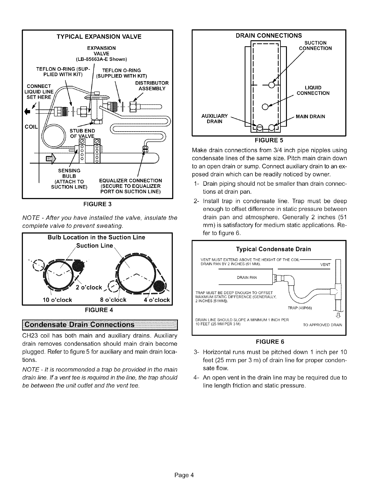
RFC Applications
1- Remove plastic cap from distributor's orifice body.
2- Install one of the o-rings supplied to the distributor ori-
fice body. See figure 2.
3- Install the refrigerant metering device (bullet) shipped
with the condensing unit into the distributor orifice
body and the liquid line seal nut section.
RFCIV INSTALLATION
__ ORIFICE
.----- O-RING
(USE ONE ONLY)
"BULLET"
ORIFICE /
SEAL
NUT SWEAT
CONNECTION
FIGURE 2
4- Place heat shield against the piping plate and around the
suction line connection. Heat shield must be in place to
guard against damage to the paint.
5- With heat shield in place, sweat in suction line. Suction
line elbow service port has no core. Secure cap to port
to prevent leakage. After procedure is completed, re-
move heat shield.
6- Refer to instructions provided with condensing unit for
leak testing, evacuating and charging procedures.
TXV Applications
1 - Loosen the liquid line seal nut at the point that the liq-
uid line exits the coil.
2 - Remove and discard the rubber grommet and metal
slug from the inside of the seal nut.
3 - Slide the liquid line stub (provided in the bag assem-
bly) through the seal nut.
4 - Braze the liquid line to the liquid line stub/seal nut as-
sembly.
5 - Apply a small amount of refrigerant oil to the O-ring
(provided in the bag assembly) and install it on the liq-
uid line orifice housing. Insert the stubbed end of the
expansion valve into the liquid line orifice housing and
tighten the expansion valve seal nut. See figure 3.
6 - Apply a small amount of refrigerant on the provided
Teflon washer provided with the expansion valve kit.
Install the washer on the threaded side of the expan-
sion valve. Tighten the liquid line seal nut on the
threads of the expansion valve. See figure 3.
7 - Place the provided heat shield over the piping plate
and around the suction line connection.
8 - With the heat shield in place, sweat in suction-line el-
bow (provided) and the suction line.
9 - Attach the expansion valve sensing bulb on a a hori-
zontal section of the suction line in the 2, 4, 8, or 10
o'clock position. The position of the sensing bulb is
critical to ensure that the systems performs prop-
erly. Refer to figure 4.
NOTE -Do not position the sensing bulb at the bottom
of the suction line. The refrigerant/oil mixture will not
allow a true temperature reading to be transferred to
the sensing bulb.
10 - Refer to the instructions that are provided with the con-
densing unit for leak testing, evacuating, and charging
procedures.
Page 3
TYPICAL EXPANSION VALVE
EXPANSION
VALVE
(LB-85663A-E Shown)
TEFLON O-RING (SUP-
PLIED WITH KIT)
CONNECT
LIQUID LINE
SET HERE
i
TEFLON O-RING
(SUPPLIED WITH KIT)
DISTRIBUTOR
ASSEMBLY
COIL STUB END
OF VALVE
SENSING
BULB
(ATTACH TO
SUCTION LINE)
EQUALIZER CONNECTION
(SECURE TO EQUALIZER
PORT ON SUCTION LINE)
FIGURE 3
NOTE -After you have installed the valve, insulate the
complete valve to prevent sweating.
Bulb Location in the Suction Line
Suction Lin_
2 o'clock
10 o'clock 8
FIGURE 4
CH23 coil has both main and auxiliary drains, Auxiliary
drain removes condensation should main drain become
plugged, Refer to figure 5 for auxiliary and main drain loca-
tions,
NOTE -It is recommended a trap be provided in the main
drain line, If a vent tee is required in the line, the trap should
be between the unit outlet and the vent tee,
AUXILIARY
DRAIN
DRAIN CONNECTIONS
o
SUCTION
NNECT'°N
IQUID
NNECTION
N DRAIN
FIGURE 5
Make drain connections from 3/4 inch pipe nipples using
condensate lines of the same size, Pitch main drain down
to an open drain or sump, Connect auxiliary drain to an ex-
posed drain which can be readily noticed by owner,
1- Drain piping should not be smaller than drain connec-
tions at drain pan,
2- Install trap in condensate line, Trap must be deep
enough to offset difference in static pressure between
drain pan and atmosphere. Generally 2 inches (51
mm) is satisfactory for medium static applications. Re-
fer to figure 6,
Typical Condensate Drain
VENT MUST EXTEND ABOVE THE HEIGHT OF THE COIL"
DRAIN PAN BY 2 INCHES (51 MM). VENT
DRAIN PAN
TRAP MUST BE DEEP ENOUGH TO OFFSET
MAXIMUM STATIC DIFFERENCE (GENERALLY,
2 INCHES [51MM]).
DRAIN LINE SHOULD SLOPE A MINIMUM 1 INCH PER
10 FEET (25 MM PER 3 M) TO APPROVED DRAIN
FIGURE 6
3- Horizontal runs must be pitched down 1 inch per 10
feet (25 mm per 3 m) of drain line for proper conden-
sate flow.
4- An open vent in the drain line may be required due to
line length friction and static pressure.
Page 4

5- Drainsshouldbeconstructedinamannerthatwillfacil- 2-
itatefuturecleaning.
6- Auxiliarydrainshouldruntoanareawherehomeown-
erwillnoticeit draining.Theauxiliarydrainlinedoes 3-
notrequiredventingoratrap,Referto localcodes,
1- Drilltestholesinsupplyductto readpressuredrop
acrossCH23coil.Seefigure7.
Connectdraftgaugewithzeroendofscaleatairenter-
ingsideofcoil.Insert1/4inch(6mm)oftestholesin-
sidecabinet,Sealaroundtesthosewithpermagum,
AIR TEST HOLE LOCATIONS
BLOWER AIR TEST HOLES
UNIT \
_ I -_ \ ClENTcEcRNPNLEUc_IBoING
I I /\1 HORIZONTALLY
MANOMETER
FIGURE 7 TABLE 1
DRAFT GAUGE READING (DRY EVAPORATOR)
400 CFM/190 L/S PER TON
Table 1 lists a range of air volumes and equivalent draft
gauge readings, as well as maximum operating CFM
Observe draft gauge readings with blower access pan-
el in place and blower operating, If reading is low, close
adjustable pulley or wire direct drive blower to higher
speed. If reading is high, open adjustable pulley or wire
to a lower blower speed, Close blower access panel
each time to eliminate false readings.
1- Insulate refrigerant connections at CH23 coil system
suction line, Use a wrap-around insulation.
2- Set room thermostat at desired setting,
3- Pick up all shipping cartons, metal scraps, extra insula-
tion and clean up the installation area,
Air Volume Total Resistance
Model No. cfm L/s in. w.g. Pa
600 285 .05 12
CH23-21 800 380 .07 17
CH23-31 1000 470 .04 10
CH23-41 1200 565 .09 22
CH23-51 1600 755 .17 42
1800 850 .20 50
CH23-65 2000 945 .24 60
CH23-68 2200 1040 .28 70
2400 1135 .32 80
Page 5
