LENNOX Evaporator Coils Manual L0806277
User Manual: LENNOX LENNOX Evaporator Coils Manual LENNOX Evaporator Coils Owner's Manual, LENNOX Evaporator Coils installation guides
Open the PDF directly: View PDF ![]() .
.
Page Count: 6
®
,1,_2008 Lennox Industries Inc,
Dallas, Texas, USA
INSTALLATION
INSTRUCTIONS
CR33 Series Coils
EVAPORATOR COILS _ Technical
505,056M LL.L[ Publications
04108 Litho U.S.A.
Supersedes 05/05
RETAIN THESE INSTRUCTIONS FOR FUTURE
REFERENCE
WARNING
CR33 Series Coils ............................. 1
General ..................................... 1
Shipping and Packing List ...................... 1
Dry Air Charge Release ........................ 2
Plenum Installation ............................ 2
Coil Installation ................................ 3
Condensate Drain ............................. 4
Blower Speed Adjustment ...................... 4
CR33 downflow evaporator coils are designed for use with
condensing units or heat pumps. Each coil is equipped with
a compression fitting that provides convenient field instal-
lation of a refrigerant metering device. Either a refrigerant
metering orifice (provided with some Lennox condensing
units) or a thermal expansion valve (ordered separately)
may be used in condensing unit applications. A check /ex-
pansion valve (ordered separately) is the only metering de-
vice approved for use in heat pump applications.
Refer to the Lennox Engineering Handbook for proper use
of these coils with Lennox furnaces, condensing units,
heat pumps and line sets.
CAUTION
IMPORTANT
These instructions are intended as a general guide and do
not supersede local codes in any way. Consult authorities
who have jurisdiction before installation.
Package 1 of 1 contains the following:
1 - CR33 evaporator coil
1 - Bag assembly containing:
3 - Straight coil Iocators (24B, 30/36B, 30/36C,
48C, 60D)
2 - Angular and 1 straight coil Iocator (18A,
24A, 30/36A, 48B, 50/60C)
6 - #8 Screws for fastening coil Iocators
1 - Liquid line stub (3/8" copper swedged)
1- O-ring
1 - Warranty/Installation Instructions
Check equipment for shipping damage. If you find any
damage, immediately contact the last carrier.
04/08
IIIHIIIIIIIIIIIIIIIIIIIIIIIIIIIIIIIII Page 1 505,056M
IIIIIIIIIIIIIIIIIIIIIIIIIIIIIIIIIIIIIHlllllllll
The CR33 coils are shipped with a 10 psi dry air holding
charge. Puncture the suction line rubber plug to release
the charge. Remove the rubber plug.
NOTE -If there is no pressure when the rubber plug is punc-
tured, check the coil for leaks before installing the coil.
Loosen and remove the liquid line compression fitting. Re-
move and discard the plug which is in the distributor body.
AIMPORTANT
See table 1 for the dimensions of the floor opening required
to accommodate the supply air opening and the plenum. If
the unit is installed against a wall, the rear edge of the
opening must be at least 1" (25 mm) from the wall. Cut an
appropriately sized opening.
Table 1
Floor Opening Dimensions
CR33 Unit
- 18A, -24A, -24B,
-30/36A, -30136B
-30136C, -48B, -48C
-50/60C, -60D
Side to Side
14-1/4"
(394mm)
19 (483mm)
22-1/2"
(571mm)
Front to Rear
23" (584mm)
I. Lower plenum through floor opening--Align the
the base of the unit with the matching plenum, then
lower the unit over the plenum. The coil cabinet must
be level or sloped slightly toward the drain outlet and
secured and sealed to the plenum, If the furnace and
coil cabinet are the same size, skip to step 3.
CAUTION
I_'_/i_ E--I,_=-]_2_1_ BJ_ [_J_Jl_I_
2, Coil Cabinet Width--Install the provided coil Iocator
brackets on the coil. Align the coil Iocator brackets with
the rear and sides of the coil cabinet. Figure 1 illus-
trates how the furnace, coil, and coil Iocator brackets
fit together.
CAUTION
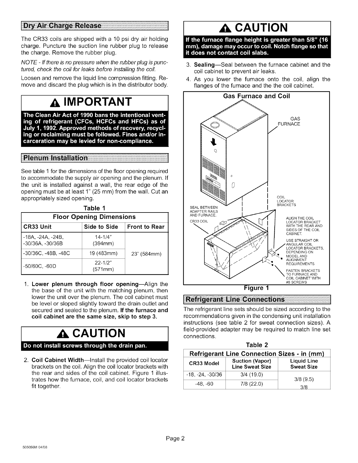
3. Sealing--Seal between the furnace cabinet and the
coil cabinet to prevent air leaks.
4. As you lower the furnace onto the coil, align the
flanges of the furnace and the the coil cabinet.
Gas Furnace and Coil
SEAL BETWEEN
ADAPTER RAILS
AND FURNACE.
CR33 COIL
o
0
Figure 1
GAS
FURNACE
COIL
LOCATOR
BRACKETS
ALIGN THE COIL
LOCATOR BRACKET
WITH THE REAR AND
SIDES OF THE COIL
CABINET.
USE STRAIGHT OR
i ANGULAR COIL
LOCATOR BRACKETS,
DEPENDING ON
:_._ MODEL AND
! ALIGNMENT
-_ REQUIREMENTS
X ASTEN BRACKETS
TO FURNACE AND
COIL CABINET WITH
#8 SCREWS
The refrigerant line sets should be sized according to the
recommendations given in the condensing unit installation
instructions (see table 2 for sweat connection sizes). A
field-provided adapter may be required to match line set
connections.
Table 2
Refrigerant Line Connection Sizes - in (mm)
CR33 Model Suction (Vapor) Liquid Line
Line Sweat Size Sweat Size
-18, -24, -30/36 314(19.0) 3/8(9.5)
-48,-60 7/8 (22.0) 3/8
505056M 04/08
Page 2
1. Placeafield-providedheatshield,suchasawetrag,
againstthepipingplateandaroundthepipingstubs,
andsweatinthesuctionline.Theheatshieldmustbe
inplacetoguardagainstheatdamagetothepaint.
2. Slidetheliquidlinecompressionnutontotheprovided
liquidlinestub.Insertthefield-suppliedliquidlineinto
theliquidlinestubforbrazing.
3. Brazeliquidlineand coilconnections.Usea silver
alloybrazingrod(5or6percentsilveralloyforcopper-
to-copperconnectionsor 45 percentsilveralloyfor
copper-to-brassorcopper-to-steelconnections).
4. Removetheheatshieldafterbrazingandallowthe
connectionstocool.
5. Selecttheappropriaterefrigerantmeteringdevice-
Refrigerant Flow Control Orifice or Expansion
Valve.
Install either a Refrigerant Flow Control Orifice or (Check/)
Thermal Expansion Valve. Refer to outdoor unit bulletins
for approved metering device.
Refrigerant Flow Control Orifice
To install the Refrigerant Flow Control Orifice:
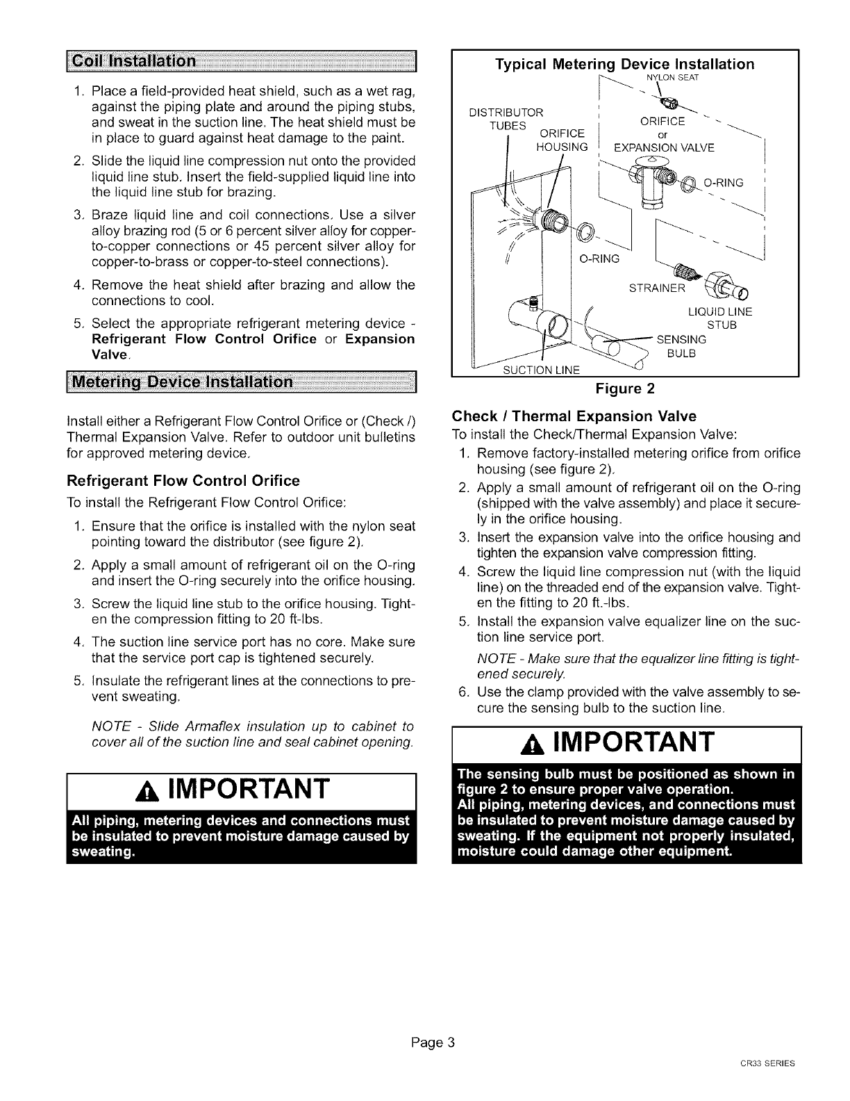
1. Ensure that the orifice is installed with the nylon seat
pointing toward the distributor (see figure 2).
2. Apply a small amount of refrigerant oil on the O-ring
and insert the O-ring securely into the orifice housing.
3. Screw the liquid line stub to the orifice housing. Tight-
en the compression fitting to 20 ft-lbs.
4. The suction line service port has no core. Make sure
that the service port cap is tightened securely.
5. Insulate the refrigerant lines at the connections to pre-
vent sweating.
NOTE -Slide Armaflex insulation up to cabinet to
cover all of the suction line and seal cabinet opening.
IMPORTANT
Typical Metering Device Installation
NYLON SEAT
DISTRIBUTOR _ ORIFICE
TUBES ORIFICE or
HOUSING EXPANSION VALVE
O-RING
SUCTION LINE
O-RING
STRAINER _)
LIQUID LINE
STUB
SENSING
BULB
Figure 2
Check /Thermal Expansion Valve
To install the Check/Thermal Expansion Valve:
1. Remove factory-installed metering orifice from orifice
housing (see figure 2).
2. Apply a small amount of refrigerant oil on the O-ring
(shipped with the valve assembly) and place it secure-
ly in the orifice housing.
3. Insert the expansion valve into the orifice housing and
tighten the expansion valve compression fitting.
4. Screw the liquid line compression nut (with the liquid
line) on the threaded end of the expansion valve. Tight-
en the fitting to 20 ft.qbs.
5. Install the expansion valve equalizer line on the suc-
tion line service port.
NOTE -Make sure that the equalizer line fitting is tight-
ened securely.
6. Use the clamp provided with the valve assembly to se-
cure the sensing bulb to the suction line.
Zi, IMPORTANT
Page 3
CR33 SERIES
Before connecting drain line(s), check drain hole(s) to
verify that drain opening is fully open and free of any de-
bris. Also check to make sure that no debris has fallen into
the drain pan during installation that may plug up the drain
opening,
Make drain connections from the 3/4" (19 mm) pipe nipple
on pan with a 3/4" (19 mm) drain pipe. Route drain pipe
downward to an open drain or sump, Never connect drain
to a closed system.
Connect main condensate drain and route downward to an
open drain or sump. Do not connect drain to a closed waste
system. See figure 3 for typical condensate trap configura-
tion.
Typical Condensate Drain
VENT MUST EXTEND ABOVE THE HEIGHT OF THE COIL"
DRAIN PAN BY 2 INCHES (51 MM). VENT
DRAIN PAN
TRAP MUST BE DEEP ENOUGH TO OFFSET
MAXIMUM STATIC DIFFERENCE (GENERALLY,
2 INCHES [51MM]).
DRAIN LINE SHOULD SLOPE A MINIMUM 1 INCH PER
10 FEET (25 MM PER 3 M) TO APPROVED DRAIN
Figure 3
The following practices are recommended to ensure con-
densate removal:
• Drain piping should not be smaller than the drain con-
nections at drain pan.
• A trap must be installed in the main drain line.
• The trap must be deep enough to offset the difference
in static pressure between drain pan and atmosphere.
Generally, two inches is satisfactory for medium static
applications.
• Horizontal runs must be sloped 1" (25.4mm) per 10'
(3m) of drain line to offset friction.
• An open vent in the drain line, as illustrated in figure 3,
should be used to overcome line length, friction and stat-
ic pressure.
• Drains should be constructed in a manner to facilitate
future cleaning and not interfere with filter access as
illustrated in figure 3.
• Auxiliary drain should run to an area where homeown-
er will notice it draining. The auxiliary drain line does
not required venting or a trap. Refer to local codes.
Proper air volume MUST be provided over the evaporator
coil. To ensure that the static pressure is within the proper
range, take a draft gauge reading as follows:
CAUTION
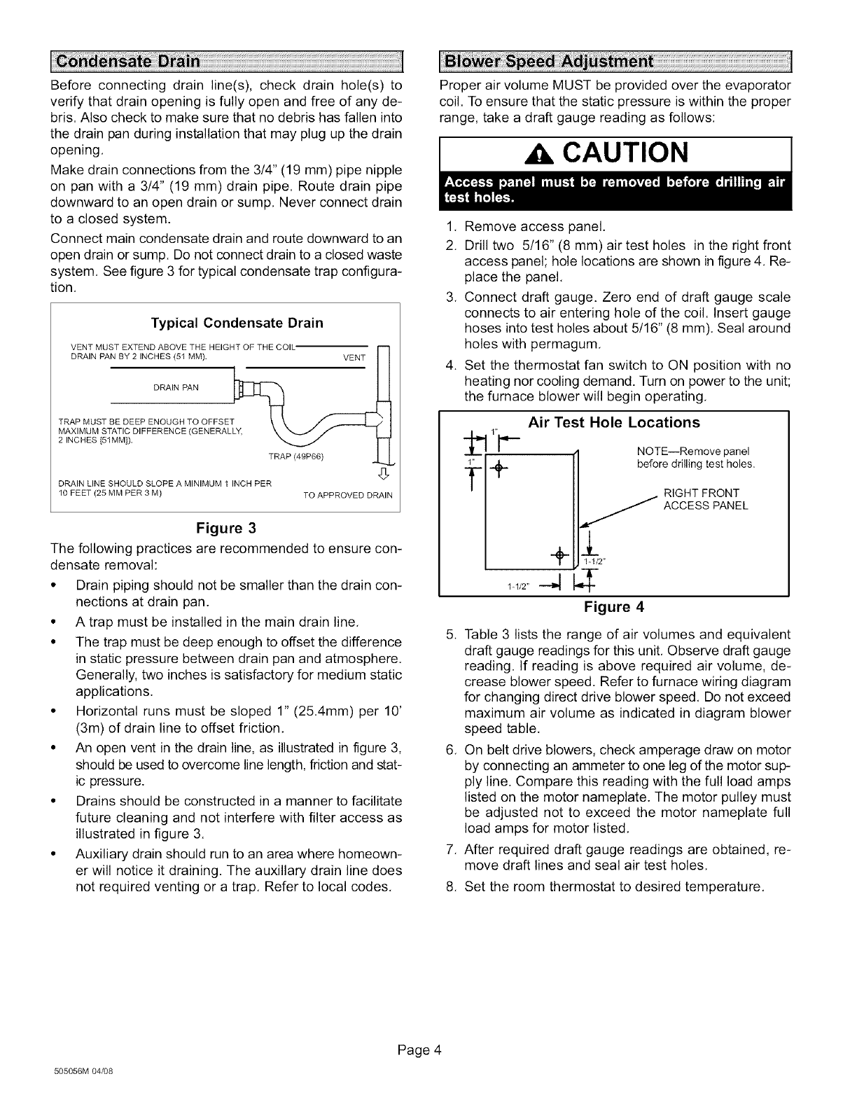
1, Remove access panel.
2. Drill two 5/16" (8 mm) air test holes in the right front
access panel; hole locations are shown in figure 4. Re-
place the panel,
3. Connect draft gauge. Zero end of draft gauge scale
connects to air entering hole of the coil. Insert gauge
hoses into test holes about 5/16" (8 mm), Seal around
holes with permagum,
4. Set the thermostat fan switch to ON position with no
heating nor cooling demand. Turn on power to the unit;
the furnace blower will begin operating,
Air Test Hole Locations
NOTE--Remove panel
before drilling test holes.
RIGHT FRONT
ACCESS PANEL
+l 1-1/2"
1/2-4
Figure 4
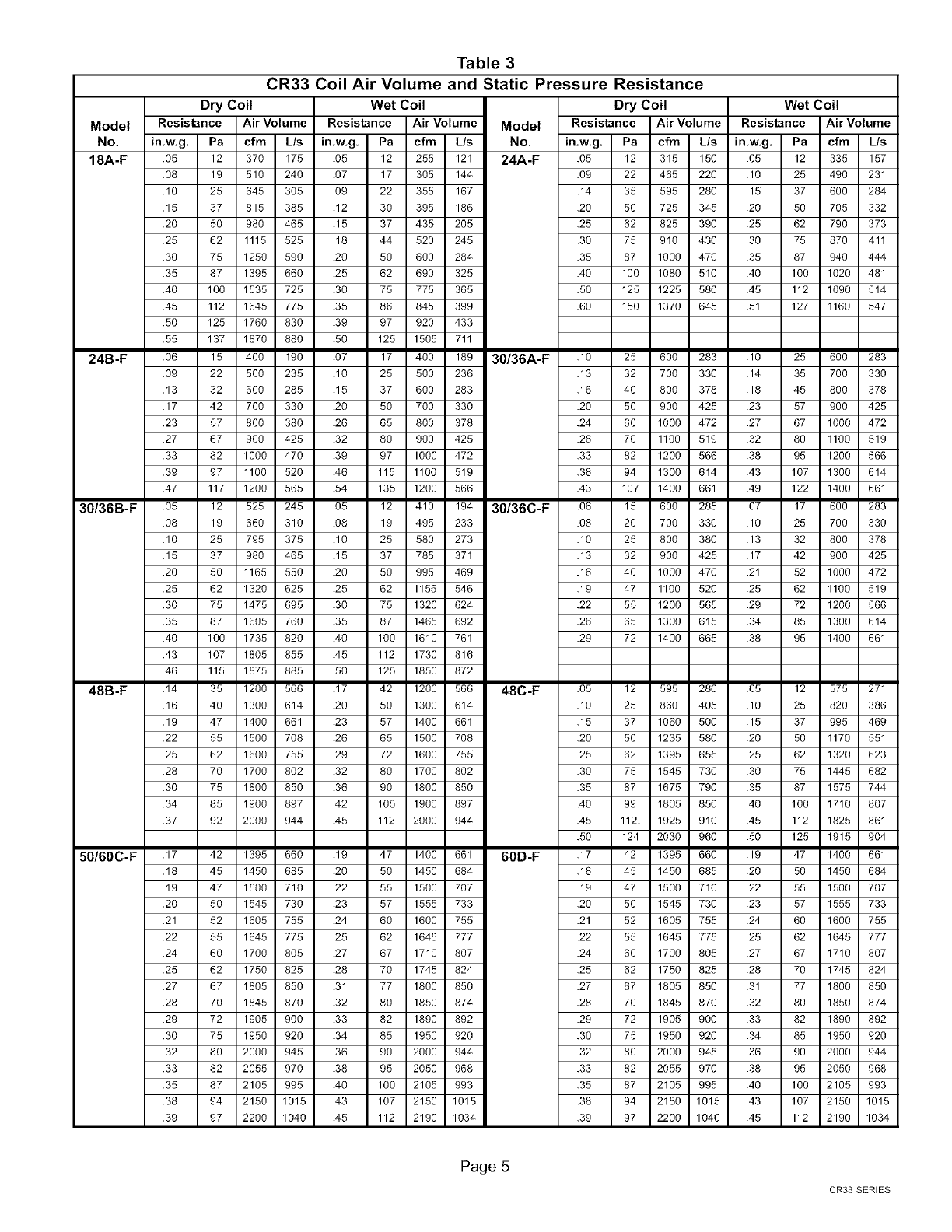
5. Table 3 lists the range of air volumes and equivalent
draft gauge readings for this unit, Observe draft gauge
reading. If reading is above required air volume, de-
crease blower speed, Refer to furnace wiring diagram
for changing direct drive blower speed, Do not exceed
maximum air volume as indicated in diagram blower
speed table,
6. On belt drive blowers, check amperage draw on motor
by connecting an ammeter to one leg of the motor sup-
ply line. Compare this reading with the full load amps
listed on the motor nameplate. The motor pulley must
be adjusted not to exceed the motor nameplate full
load amps for motor listed,
7. After required draft gauge readings are obtained, re-
move draft lines and seal air test holes,
8. Set the room thermostat to desired temperature.
505056M 04/08
Page 4
Model
No.
18A-F
Table 3
CR33 Coil Air Volume and Static Pressure Resistance
Dry Coil Wet Coil Dry Coil Wet Coil
Resistance Air Volume Resistance Air Volume Model Resistance Air Volume Resistance Air Volume
in.w.g. Pa cfm L/s in.w.g. Pa cfm L/s No. in.w.g. Pa cfm L/s in.w.g. Pa cfm L/s
.05 12 370 175 .05 12 255 121 24A-F .o5 12 315 150 .05 12 335 157
.08 19 510 240 .07 17 305 144 .09 22 465 220 .10 25 490 231
.10 25 645 305 .09 22 355 167 .14 35 595 280 .15 37 600 284
.15 37 815 385 .12 30 395 186 .20 50 725 345 .20 50 705 332
.20 50 980 465 .15 37 435 205 .25 62 825 390 .25 62 790 373
.25 62 1115 525 .18 44 520 245 .30 75 910 430 .30 75 870 411
.30 75 1250 590 20 50 600 284 .35 87 1000 470 .35 87 940 444
.35 87 1395 660 25 62 690 325 .40 100 1080 510 .40 100 1020 481
.40 100 1535 725 .30 75 775 365 .50 125 1225 580 .45 112 1090 514
.45 112 1645 775 .35 86 845 399 .60 150 1370 645 .51 127 1160 547
.50 125 1760 830 .39 97 920 433
.55
24B-F .06
.09
.13
.17
.23
.27
.33
.39
.47
30/36B-F .05
.08
.10
.15
.20
.25
.30
.35
.40
.43
.46
48B-F .14
.16
.19
.22
.25
.28
.30
.34
.37
50/60C-F .17
.18
.19
.20
.21
.22
.24
.25
.27
.28
.29
.30
.32
.33
.35
.38
.39
137 1870 880 .50 125 1505 711
15 400 190 .07 17 400 189 30/36A-F .10 25 600 283
22 500 235 .10 .13 32 700 330
32 600 285 .15 .16 40 800 378
42 700 330 .20 .20 50 900 425
57 800 380 .26 .24 60 1000 472
67 900 425 .32 .28 70 1100 519
82 1000 470 .39 .33 82 1200 566
97 1100 520 .46 .38 94 1300 614
117 1200 565 .54 .43 107 1400 661
12 525 245 .05 15 600 285
19 660 310 .08 .08 20 700 330
25 795 375 .10 .10 25 800 380
37 980 465 .15 .13 32 900 425
50 1165 550 .20 .16 40 1000 470
62 1320 625 .25 .19 47 1100 520
75 1475 695 .30 .22 55 1200 565
87 1605 760 .35 .26 65 1300 615
100 1735 820 .40 .29 72 1400 665
107 1805 855 .45
115 1875 885 .50
35 1200 566 .17
40 1300 614 .20
47 1400 661 .23
55 1500 708 .26
62 1600 755 .29
70 1700 802 .32
75 1800 850 .36
85 1900 897 .42
92 2000 944 .45
25 500 236
37 600 283
50 700 330
65 800 378
80 900 425
97 1000 472
115 1100 519
135 1200 566
12 410 194 30/36C-F .06
19 495 233
25 580 273
37 785 371
50 995 469
62 1155 546
75 1320 624
87 1465 692
100 1610 761
112 1730 816
125 1850 872
42 1200 566
50 1300 614
57 1400 661
65 1500 708
72 1600 755
80 1700 802
90 1800 850
105 1900 897
112 2000 944
42 1395 660 .19 47 1400 661
45 1450 685 .20 50 1450 684
47 1500 710 .22 55 1500 707
50 1545 730 .23 57 1555 733
52 1605 755 .24 60 1600 755
55 1645 775 .25 62 1645 777
60 1700 805 .27 67 1710 807
62 1750 825 .28 70 1745 824
67 1805 850 .31 77 1800 850
70 1845 870 .32 80 1850 874
72 1905 900 .33 82 1890 892
75 1950 920 .34 85 1950 920
80 2000 945 .36 90 2000 944
82 2055 970 .38 95 2050 968
87 2105 995 .40 100 2105 993
94 2150 1015 .43 107 2150 1015
97 2200 1040 .45 112 2190 1034
48C-F .05
.10
.15
.20
.25
.30
.35
.40
.45
.50
60D-F .17
.18
.19
.20
.21
.22
.24
.25
.27
.28
.29
.30
.32
.33
.35
.38
.39
12 595 280
25 860 405
37 1060 500
50 1235 580
62 1395 655
75 1545 730
87 1675 790
99 1805 850
112. 1925 910
124 2030 960
42 1395 660
45 1450 685
47 1500 710
50 1545 730
52 1605 755
55 1645 775
60 1700 805
62 1750 825
67 1805 850
70 1845 870
72 1905 900
75 1950 920
80 2000 945
82 2055 970
87 2105 995
94 2150 1015
97 2200 1040
.10 25 600 283
.14 35 700 330
.18 45 800 378
.23 57 900 425
.27 67 1000 472
.32 80 1100 519
.38 95 1200 566
.43 107 1300 614
.49 122 1400 661
.07 17 600 283
.10 25 700 330
.13 32 800 378
.17 42 900 425
.21 52 1000 472
.25 62 1100 519
.29 72 1200 566
.34 85 1300 614
.38 95 1400 661
.05 12 575 271
.10 25 820 386
.15 37 995 469
.20 50 1170 551
.25 62 1320 623
.30 75 1445 682
.35 87 1575 744
.40 100 1710 807
.45 112 1825 861
.50 125 1915 904
.19 47 1400 661
.20 50 1450 684
.22 55 1500 707
.23 57 1555 733
.24 60 1600 755
.25 62 1645 777
.27 67 1710 807
.28 70 1745 824
.31 77 1800 850
.32 80 1850 874
.33 82 1890 892
.34 85 1950 920
.36 90 2000 944
.38 95 2050 968
.40 100 2105 993
.43 107 2150 1015
.45 112 2190 1034
Page 5
CR33 SERIES
A trained technician or service agency must perform main-
tenance and service on equipment. At the beginning of
each heating or cooling season, indoor coils should be
cleaned,
Do not use hydrofluoric acid, alkaline, or similar chemicals
on coils. These chemicals are not necessary to dissolve
salt, and may damage the fin coating. Acid washes are
used to dissolve oils and greases, which generally are not
present on most installations,
Do not use alkaline washes to dissolve oxides such as zinc
oxide, aluminum oxide, and iron oxide (rust). These three
oxides are more corrosion-resistant than base metals. Dis-
solving or removing them will cause an increase in corro-
sion.
CAUTION
Cleaning the coil:
1. Remove the coil from the cabinet and take the coil to
an appropriate place to clean it,
2. Vacuum or brush the coil to remove matted and sur-
face debris from the fin. Use vacuum attachments and
/or brushes that are non-destructive to fins,
3. If oil deposits are present, spray the coil with ordinary
household liquid detergent, Allow detergent to soften
deposits. Wait 10 minutes,
,
5,
NOTE -For units in coastal regions, fresh water will
dissolve salt deposits. (Wash coils with fresh water at
least every six months,)
Spray the coil at a vertical angle of 30 to 45 degrees
with a constant stream of water at moderate pressure.
A pressure washer with a fan nozzle will work best, Do
not spray the coil from a horizontal direction,
Direct the spray so that any debris is washed out of the
coil and base pan, For most residential units, hot water
is not necessary,
NOTE -Attempting to back flush from the inside of the
coil will require removing parts from the unit, and it
may be very difficult to flush the whole coil surface. At-
tempting to blow water through a coil will slow the wa-
ter stream and reduce the flushing action of the outer
fin surface.
6. Replace the coil into the cabinet,
505056M 04_8
Page 6
