LENNOX Controls And HVAC Accessories Manual L0806301
User Manual: LENNOX LENNOX Controls and HVAC Accessories Manual LENNOX Controls and HVAC Accessories Owner's Manual, LENNOX Controls and HVAC Accessories installation guides
Open the PDF directly: View PDF ![]() .
.
Page Count: 8
q _ _ Technical
J .J L Publications
Lithe U.S.A.
_;)2007
HEAT PUMP UNITS
KITS AND ACCESSORIES
503,802M
11/2007
Supersedes 2/98 DEFROST CONTROL KIT
INSTALLATION INSTRUCTIONS FOR DEFROST CONTROL KIT (23L00 - LB-93614)
USED WITH HP14 t16 t18 t20 tCHP16 t20 t24 tAND CHP15-261 TO 461 UNITS
Package 1 of I contains:
1--Defrost control assembly (CMC1 & K4)
2- Wiring diagrams stickers
1--Bag assembly containing:
1- Defrost thermostat switch ($6)
1- Defrost (refrigerant-type) pressure switch
($46) assembly (HP14, HP16 and HP18)
1- 1/2" snap-hole plug (HP16 units only)
8- Wire nuts
1- Wire tie
2- Insulating sleeves
2- #8 - 32 X 1/2" Screws
1- Saddle valve (HP14 and HP18)
This defrost control kit replaces the existing defrost
control systems in HP14, HP16, HP18, HP20, CHP16,
CHP20, CHP24 and CHP15-261 to 461 units.
This kit is used to upgrade units to a temperature initiated /
pressure terminated defrost system, Various defrost
components are used in each unit, Once updated, all
units will contain these four defrost components:
CMC1 Defrost Control
S6 Defrost Thermostat Switch
S46 Defrost Pressure Switch (refrigerant type)
K4 Defrost Relay
The replacement defrost control system checks every 90
minutes (factory-set) to determine if defrost is necessary.
If the defrost thermostat senses a temperature below
35°F (1,6°C), the thermostat contacts close to initiate
defrost. When the pressure level sensed by defrost
pressure switch rises to 275 psi, switch contacts open and
defrost terminates.
1 - Turn off electrical power to unit at disconnect switch,
2- Remove access panels and remove defrost pressure
switch cover.
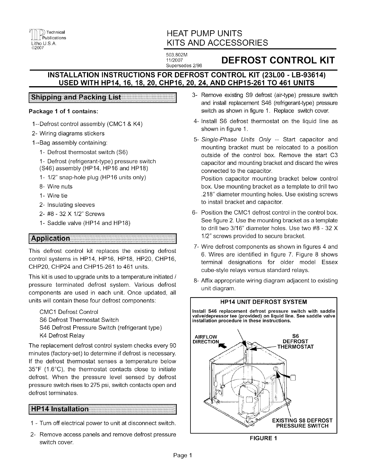
3- Remove existing S9 defrost (air-type) pressure switch
and install replacement S46 (refrigerant-type) pressure
switch as shown in figure 1, Replace switch cover.
4- Install S6 defrost thermostat on the liquid line as
shown in figure 1,
5-Single-Phase Units Only -- Start capacitor and
mounting bracket must be relocated to a position
outside of the control box, Remove the start C3
capacitor and mounting bracket and discard the wires
connected to the capacitor.
Position capacitor mounting bracket below control
box, Use mounting bracket as a template to drill two
.218" diameter mounting holes. Use existing screws
to install bracket and capacitor,
6- Position the CMCl defrost control in the control box,
See figure 2, Use the mounting bracket as a template
to drill two 3/16" diameter holes. Use two #8 - 32 X
1/2" screws provided to secure bracket,
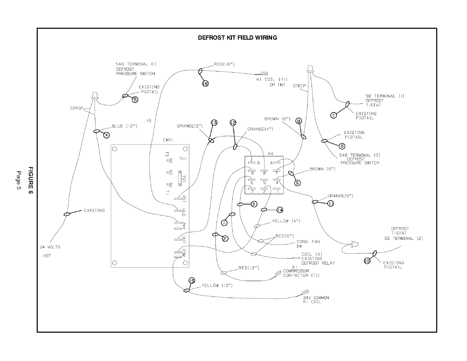
7- Wire defrost components as shown in figures 4 and
6, Wires are identified in figure 7, Figure 8 shows
terminal designations for older model Essex
cube-style relays versus standard relays,
8- Affix appropriate wiring diagram adjacent to existing
unit diagram.
HP14 UNIT DEFROST SYSTEM
Install S46 replacement defrost pressure switch with saddle
valve/depressor tee (provided) on liquid line. See saddle valve
installation procedure in these instructions.
AIRFLOW $6
DIRECTION DEFROST
;TAT
<
EXISTING $8 DEFROST
PRESSURE SWITCH
FIGURE 1
Page 1
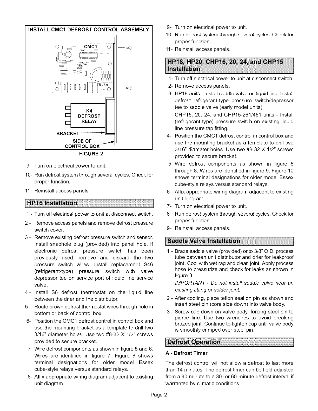
INSTALL CMC1 DEFROST CONTROL ASSEMBLY
K4
DEFROST
RELAY
BRACKET
SIDE OF
CONTROL BOX
FIGURE 2
O
9- Turn on electrical power to unit,
10- Run defrost system through several cycles, Check for
proper function,
11- Reinstall access panels,
1 - Turn off electrical power to unit at disconnect switch,
2 - Remove access panels and remove defrost pressure
switch cover,
3 - Remove existing defrost pressure switch and sensor.
Install snaphole plug (provided) into panel hole, If
electronic defrost pressure switch has been
previously used, remove and discard the two
pressure switch wires. Install replacement $46
(refrigerant-type) pressure switch with valve
depressor tee on service port of liquid line service
valve,
4- Install $6 defrost thermostat on the liquid line
between the drier and the distributor.
5 - Route brown defrost thermostat wires through hole in
bottom or back of control box,
6- Position the CMC1 defrost control in control box and
use the mounting bracket as a template to drill two
3/16" diameter holes, Use two #8-32 X 1/2" screws
provided to secure bracket,
7- Wire defrost components as shown in figure 5 and 6,
Wires are identified in figure 7, Figure 8 shows
terminal designations for older model Essex
cube-style relays versus standard relays,
8- Affix appropriate wiring diagram adjacent to existing
unit diagram,
9- Turn on electrical power to unit,
10- Run defrost system through several cycles, Check for
proper function,
11- Reinstall access panels,
1- Turn off electrical power to unit at disconnect switch,
2- Remove access panels.
3- HP18 units - Install saddle valve on liquid line, Install
defrost refrigerant-type pressure switch/depressor
tee to saddle valve (early model units),
CHP16, 20, 24, and CHP15-261/461 units - Install
(refrigerant-type) pressure switch on existing liquid
line pressure tap fitting.
4- Position the CMC1 defrost control in control box and
use the mounting bracket as a template to drill two
3/16" diameter holes. Use two #8-32 X 1/2" screws
provided to secure bracket,
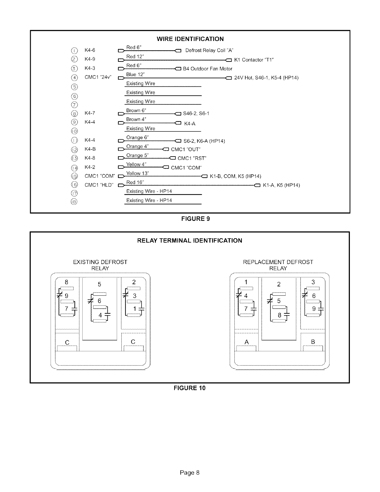
5-Wire defrost components as shown in figure 5
through 8. Wires are identified in figure 9. Figure 10
shows terminal designations for older model Essex
cube-style relays versus standard relays.
6- Affix appropriate wiring diagram adjacent to existing
unit diagram,
7- Turn on electrical power to unit,
8- Run defrost system through several cycles, Check for
proper function,
9- Reinstall access panels,
1 - Braze saddle valve (provided) onto 3/8" O.D. process
tube between unit distributor and drier for leakproof
joint, Cool with wet rag and clean joint. Apply process
hose to pressurize and check for leaks as shown in
figure 3,
IMPORTANT -Do not install saddle valve near an
existing fitting or solder joint.
2 - After cooling, place teflon seal on pin as shown and
insert steel pin (core side down) into valve body.
3 - Screw cap down on valve body, forcing steel pin to
pierce line. Use two wrenches to avoid breaking
brazed joint, Continue to tighten cap until valve body
is smoothly crimped over steel pin,
A - Defrost Timer
The defrost control will not allow a defrost to last more
than 14 minutes, The defrost timer can be field adjusted
from a 90-minute to a 30- or 60-minute defrost interval if
warranted by climatic conditions,
Page 2
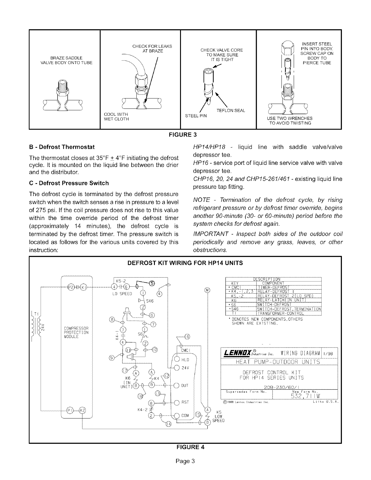
BRAZE SADDLE
VALVE BODY ONTO TUBE
CHECK FOR LEAKS
AT BRAZE
COOL WITH
WET CLOTH
CHECK VALVE CORE
TO MAKE SURE
iT IS TIGHT
_ TEFLON SEAL
STEEL PIN
._, INSERT STEEL
PIN INTO BODY.
SCREW CAP ON
BODY TO
I_1 P,EROE TUBE
USE TWO WRENCHES
TO AVOID TWiSTiNG
FIGURE 3
B - Defrost Thermostat
The thermostat closes at 35°F + 4°F initiating the defrost
cycle. It is mounted on the liquid line between the drier
and the distributor.
C - Defrost Pressure Switch
The defrost cycle is terminated by the defrost pressure
switch when the switch senses a rise in pressure to a level
of 275 psi. If the coil pressure does not rise to this value
within the time override period of the defrost timer
(approximately 14 minutes), the defrost cycle is
terminated by the defrost timer. The pressure switch is
located as follows for the various units covered by this
instruction:
HP14/HP18 liquid line with saddle valve/valve
depressor tee.
HPf6 - service port of liquid line service valve with valve
depressor tee.
CHPf6, 20, 24 and CHP15-261/461 - existing liquid line
pressure tap fitting.
NOTE -Termination of the defrost cycle, by rising
refrigerant pressure or by defrost timer override, begins
another 90-minute (30- or @-minute) period before the
system checks for defrost again.
IMPORTANT -Inspect both sides of the outdoor coil
periodically and remove any grass, leaves, or other
obstructions.
DEFROST KIT WIRING FOR HP14 UNITS
COMPRESSOR
PRO1 EC1 i ON
MOD[ LE
LO SPEED
K6
(IN
UNIT)t
DESCRIPIION
KEY COMPONENT
* CMCI IlMER=DEFROSI
*K4,-I,2,5 RELAY-DEPROSI]
KS,-_ RELAY@EFROSI 2(LO SPD)
K6 RELAY-LATCH(IN UNIT)
"86 SWITCH-DEFROST
"$46 SWI[CH-DEFROS1,TERMINAfION
T] 1RANS[:ORMER CONqROL
* DENOTES NEW COMPONENTS,OTHERS
SHOWN ARE EXTSTTNG,
= =
HEAT PUMP OUTDOOR UNITS
DEFROST CONTROL KIT
FOR HPI4 SERIES UNITS
208 230/60/I
Supersedes or_ No. New orm N_.
.552,7 I IW
(_ 1998 Lenno× [_dus!r e_ 1_¢ h i _ h 0 _U , S A .
K5
LOW
SPEED
FIGURE 4
Page 3

DEFROST KIT WIRING FOR
HP16, HP18, HP20 AND CliP15 UNITS
K4-3
B4
DEFROST
RELAY
(K4 ON CHPL5)
K4 2
REMOVE EXSIST!NG WIRES FROM TERMINALS
1,2,& 3 OF EXISTING DEFROST RELAY.
LEAVE REST OF WIRES ON POLES
2 & 5 AS IS.
L.eNNDX_,o_,_. WlRN@OIAGRAMJl9s....................
HEArPuMPou soo uNi -s
DEFROST CONTROL KIT
FOR HP 6,HPI8,HP20 & CHPI5
SERIES UNITS
208-250/60/I
Supersedes Form No. New Form No.
552,7lOW
(_199B Lennox Indusl_ies Inc. L fho U.S.A.
\
TBI-
CHP}5 ONLY
4}
) s4
I
D- PRESSURE
{SWITCII
KI
COMPRESSOR
CONTACTOR
124v tOM
&
w
* DENO]ES NEW COMPONENIS,O1HERS
SHOWN ARE EXISTING,
DESCRIPTION
KEY COMPONENT
BI COMPRESSOR
B4 MOTOR-FAN
..........t_M_! ...............................................................................................................................................................................................
HR}
....................._.L -I
*K4,-I,2,3
K31
54
' $6
. SS6
HEATER COMPRESOR
CONIACTOR-COMPRESSOR
RELAY DEFROST
RE1AY HARD START KIT
iSWITCH-PRESSURE,HIGH
SWITCH DEFROST
iSWlTCH-DEFROST,TERMINATION
FIGURE 5
Page 4
'-rl
"o
on m
24 VOLTS
HOT
S[RIR
DEFROST KIT FIELD WIRING
$46 TERMINAL (E)
DEFROST
PRESSURE SWITCH
BLUE (}2")
\\
EG/
EXISTING
CMC}
0
o8
..jREO(16")
KI COIL (YI)
OR (M)
o_
©
ORANGE(5") \
4_
oS
\
©/
THI
\
I
["_
STRIP
BROWN_" /\
ORANGE(4")
/
.YELLOW (iS"}
$6 TERMINAL (})
DEFROST
T-STAT
EXISTING
PIGTAIL
EXISTING
=IGTAIL
_$46 TERMINAL (2)
DEFROST
PRESSURE SWI]CH
(6")
ORANGE(6")
-_24V COMMON
KI COIL
DEFROST
T-STAT
$6 TERMINAL (2)
B4 FAN _#_
COIL (A) k..___ @_J
EXISTING
DE ROST RELAY STING
K I °IGTAIL
(I)
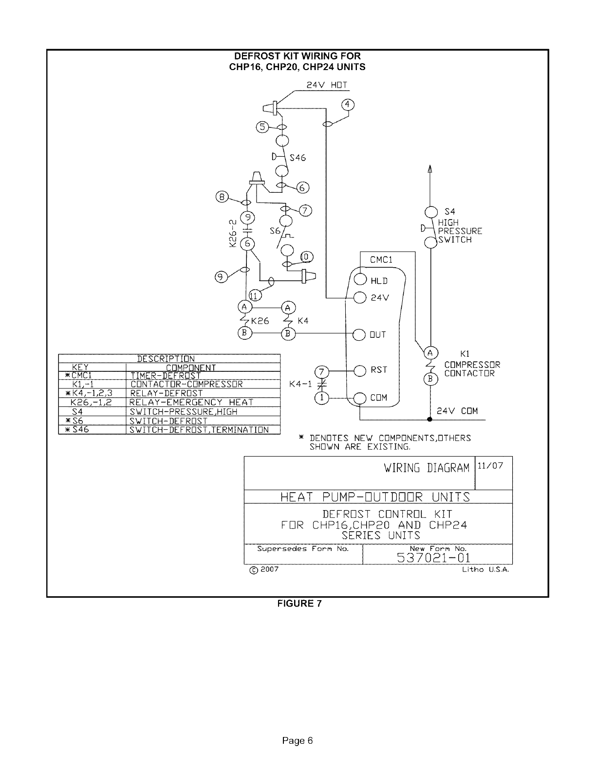
DEFROST KIT WIRING FOR
CHP16, CHP20, CHP24 UNITS
KEY
_CMCI
KI,-I
• K4,-I,2,3
K26,-I,2
$4
_$6
$46
24V HOT
DESCRIPTION
COMPONENT
TIMER-DEFROST
CDNTACTOR-CONPRESSOR
RELAY-DEFROST
RELAY-EMERGENCY HEAT
SWITCH-PRESSURE,HIGH
SWITCH-DEFROST
SWITCH-DEFROST,TERMINATION
K4-1
0 OUT
PRESSURE
SWITCH
_) K1
L COMPRESSOR
( _ CDNTACTOR
24V CON
DENOTES NEW COMPONENTS,OTHERS
SHOWN ARE EXISTING.
WIRING DIAGRAH ii/07
HEAT PUHP-DUTDDDR UNITS
DEFROST CONTROL KIT
FOR CHPI6,CHP20 AND CHP24
SERIES UNITS
Supersedes Form No, New Form No.
537021-01
C) 2007 Litho U,S,A.
FIGURE 7
Page 6
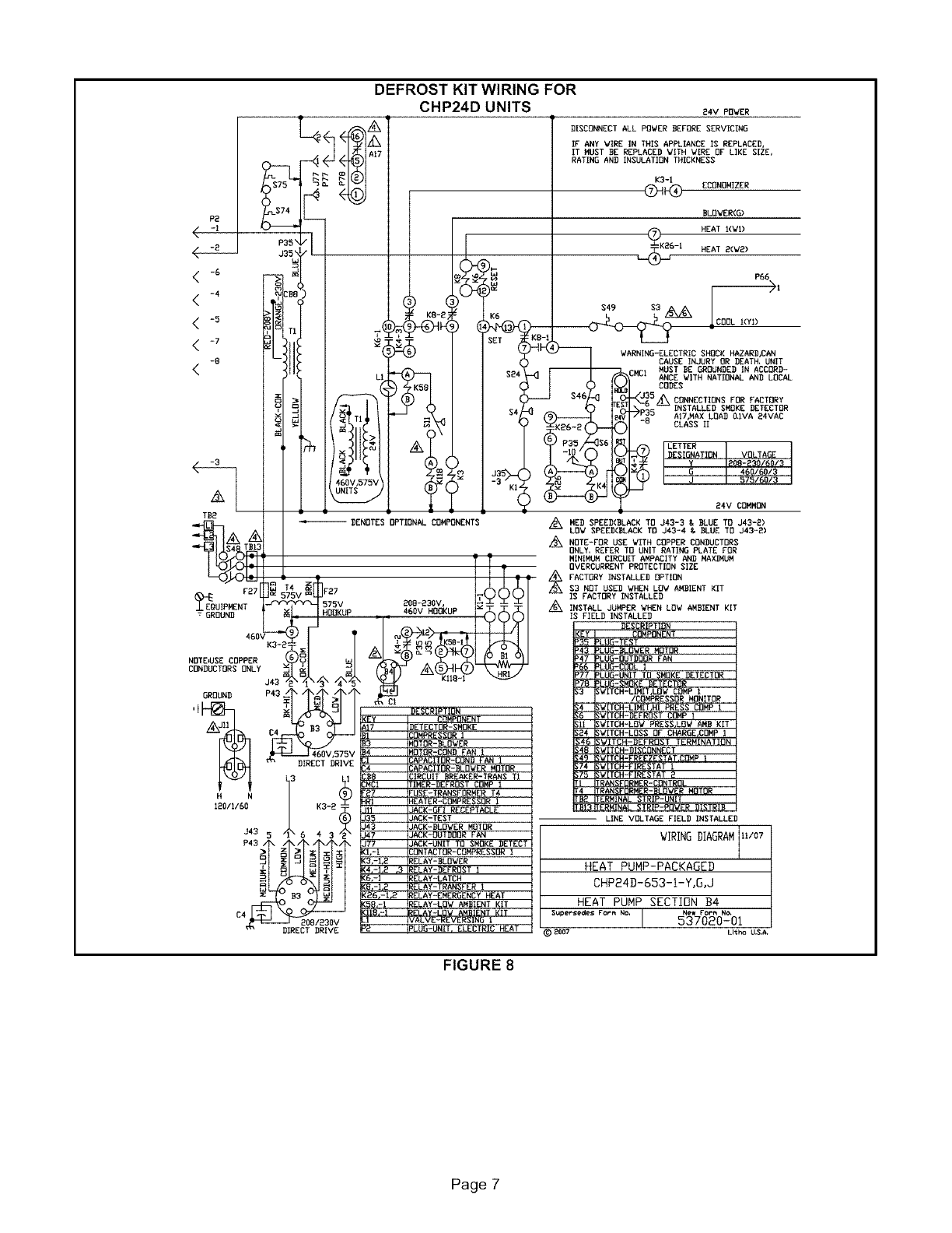
DEFROST KIT WIRING FOR
CHP24D UNITS 24V POWER
J35 •
< -6
-8
<
-3
TD2
_EOUIPMEN_ 27 575V
GROUND
460VK3-2: ._
NOTE_USE COPPER
CONBL_TORSONLY
GROUND P43
DIRECT DRIVE
2.N
J43 5 _X6 43/_
• z • z i _:
C4 208/230V
I
K6
DISCONNECT ALL POWER BEFORE SERVICINO
IF ANY WIRE IN THIS APPLIANCE IS REPLACED,
IT MUST BE REPLACED WITH VIRE OF LIKE SIZE,
RATING AND INSULATION THICKNESS
K3-1
(_ ECONOMIZER
BLOWER(O)
_._6 HEAT l(Wl)
-t HEAT 2(W2)
P66
DENOTES OPTIONAL COMPONENTS
DOB-230V,
460v HOOKUP
WARNING-ELECTRIC SHOCK HAZARD_AN
CAUSE INJURY OR DEATH, UNIT
_MCI MUST DE GROUNDED IN ACCORD-
ANCE WITH NATIONAL ANO LOCAL
CODES
//\CONNECTIONS FOR FACTORY
INSTALLED SMOKE DETECTOR
AI7.MAX LOAD O.IVA 24VAC
CLASS II
LETTER !
IDESIGNATIONI VOLTAGE
IY1208-230/60/3
57516013
24V COMMON
/_ MEO SPEED(BLACK TO J43-3 & BLUE TO J43-2)
LOW SPEED(BLACK TO J43-4 & BLUE TO J43-0)
NOTE-FOR USE WITH COPPER CONDUCTORS
ONLY, REFER TO UNIT RATING PLATE FOR
MINIMUM CIRCUIT AMPACITY AND MAXIMUM
OVERCURRENT PROTECTION SIZE
FACTORY INSTALLED OPTION
$3 NOT USED V/HEN LOW AMBIENT KIT
IS FACTORY INSTALLED
A
/6_ INSTALL JUMPER WHEN LOW AMBIENT KIT
FIELD INSTALLED
DESCRIPTION
(EY COMPONENT
'35 PLUO-TES T
43 PLUG-BLOWER MOTOR
47 PLUG-OUTDOOR PAN
PLU_-UNIT TO _MOK_ I)ET_CTOR
178 PLUG-SMOKE DETECTOR
SWITCH-LIMIT.LOW COMP 1
/COMPRESSOR MONITOR
;4 SWITCH-LIMIT HI PRESS COMP I
;6 SWITCH-DEFROST COMP I
;11 SWITCH-LOW PRESS.LOW AMD KIT
;04 SWITCH-LOSS OF CHARGE,CORP I
;4G SWITCH-DEFROST TERMINATION
;48 SWITCH-DISCONNECT
;75 SWITCH-FIR_STAT O
I TRANSFORMER-CONTROL
4 TRANSFORNER-BLOVOR MOTOR
'D_ TERMINAL STR_P-UNIT
"D13TERMINAL STRIP-POVOR DISTRID
LINE VOLTAGE FIELD INSTALLED
WIRINGDIAGRAMII/O7
HEAT PUMP-PACKAGED
CHP24D-G53-I-Y,G,JI I
HEAT PUMP SECTIrIN B4
SL_per_edes FoPr_ NO, I New FOP_ NO,
537020-01
_) _007 Lltho U.&A,
FIGURE 8
Page 7
©
©
@
©
@
©
@
@
©
@
K4-6 D
K4-9 D
K4-3 D
CMC1 "24v" D
Red 6"
Red 12"
Red 6"
Blue 12"
Existing Wire
Existing Wire
WIRE IDENTIFICATION
Existing Wire
Brown 6"
K4-7 D
Brown 4"
K44 D
Existing Wire
K4-4 I::C)Orange 6"
K4-B E:::) Orange 4"
K4-8 D Orange 5"
Yellow 4"
K4-2 D
Yellow 13"
CMC1 "COM" D
Red 16"
CMC1 "HLD" D
a Defrost Relay Coil "A"
a K1 Contactor"Tl"
a B4 Outdoor Fan Motor
<:::3 24V Hot, $46-1, K5-4 (HP14)
a s46-2, s6-1
<::3 K4-A
C:] S6-2, K6-A (HP14)
a CMC1 "OUT"
CMCl "RST"
a CMCl "COM"
4::3 K1-B, COM, K5 (HP14)
<::3 K1-A, K5 (HP14)
Existing Wire - HP14
Existing Wire - HP14
FIGURE 9
RELAY TERMINAL IDENTIFICATION
EXISTING DEFROST
RELAY
8
C:::223
C
................ i
-[333333
-_ 3
_t
_t
C
.................... i
/
J
REPLACEMENT DEFROST
RELAY
1
---4
A
2
B
.................
FIGURE 10
Page 8
