LENNOX Controls And HVAC Accessories Manual L0806307
User Manual: LENNOX LENNOX Controls and HVAC Accessories Manual LENNOX Controls and HVAC Accessories Owner's Manual, LENNOX Controls and HVAC Accessories installation guides
Open the PDF directly: View PDF ![]() .
.
Page Count: 6
_4
,1,_)2006 Lennox Industries inc.
Dallas, Texas, USA
COOLING UNITS
KITS AND ACCESSORIES
Tech nical
bHcations
Litho U.S.A.
505,224M
08/06
Supersedes 05/06
LOW AMBIENT CONTROL
KIT
INSTALLATION INSTRUCTIONS FOR LOW AMBIENT CONTROL KIT LB-101123C (68M04)
USED WITH: HSXA19-038 & XC21 CONDENSING UNITS;
HPXA19-038 & XP19 HEAT PUMP UNITS
Package 1 of 1 contains the following:
1 - Low ambient pressure switch assembly 83L6001
(S11)
2 - Relays - part #69J8001 (K58 and K159)
10 - 20" Lengths of wire (c/w 3/16" Female quick con-
nects on one end of each wire)
10 - Wire nuts
4-ll10-16 X 5/8" S.D.S.T. screws
1 - Schrader depressor tee with seal cap
Ordered separately:
1 - Properly sized freezestat (S49)
AIMPORTANT
The low ambient control pressure switch (Sll) cycles the
outdoor fan, while allowing continuous compressor opera-
tion during a cooling demand. This intermittent outdoor fan
operation maintains a minimum pressure differential
across the expansion device as the ambient temperature
drops, thus reducing capacity losses during low ambient
conditions. The freezestat (ordered separately) senses
suction line temperature and cycles the compressor off
when suction line temperature falls below its setpoint. This
kit is designed for use in ambient temperatures that are no
lower than 30°F (-1°C) unless otherwise noted in the Engi-
neering Handbook. Use this kit only with HSXA19-038,
XC21, HPXA19-038, or XP19 units in R410A refrigerant
applications.
NOTE -This kit may be applied in expansion valve sys-
tems only. It is not suitable for use in systems which use
capillary tube metering devices.
All units are factory-equipped with a crankcase heater.
1 - Turn off the electrical power to the unit.
2- Remove compressor compartment access panel, if
applicable.
3 - Install provided low ambient pressure switch on open
port (no valve core) of provided tee fitting.
NOTE -Pressure switch must be installed before
tee is installed to avoid refrigerant loss.
4-Install tee fitting on condensing unit liquid line service
port.
5 - Install cap on valve core port and tighten to 6 to 8 ft.-
Ibs.
6 - Route pressure switch wires into control box and con-
nect per applicable unit wiring diagram.
7 - A freezestat, sized per table 1 and ordered separately,
must be installed. Install the freezestat near the evapo-
rater coil discharge line (on the last 5/16" or 3/8" bend
of the indoor coil) or on the suction line.
Table 1
Freezestat Selection
Tubing Wire Wire Lennox
Size Length Gauge Part No.
3/8" 90-13/16" 18 93G35
112" 140-13t16" 18 39H29
5/8" 36-1/2" 18 50A93
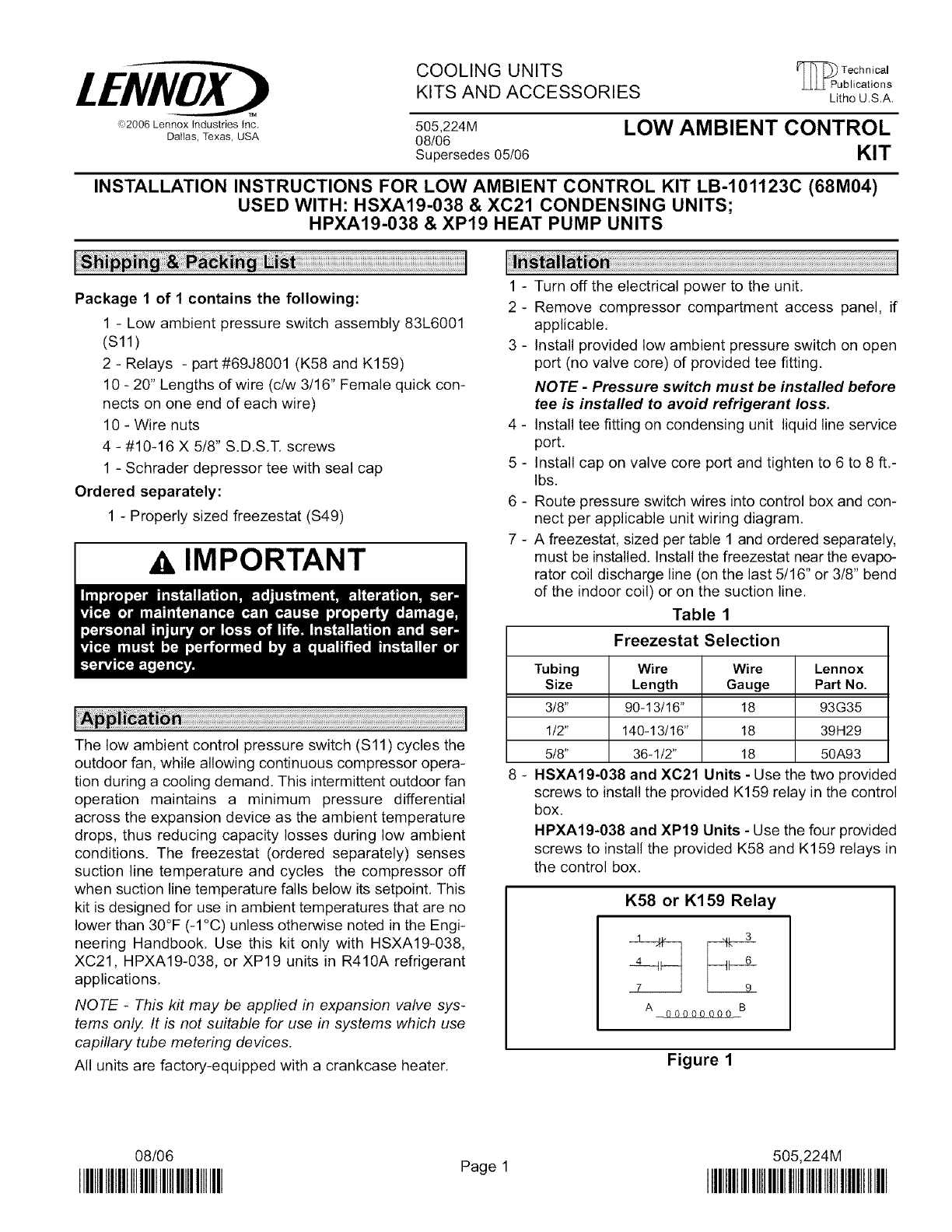
8 - HSXA19-038 and XC21 Units -Use the two provided
screws to install the provided K159 relay in the control
box.
HPXA19-038 and XP19 Units - Use the four provided
screws to install the provided K58 and K159 relays in
the control box,
K58 or K159 Relay
7 9
A_B
Figure 1
08/06
IIIIIIIIIIIIIIIIIIIIIIIIIIIIHIIIIIIII Page 1 505,224M
IIIIIIIIIIIIIIIIIIIIIIIIIIIIIIIIIIIIIIIIIIIIIIIIII
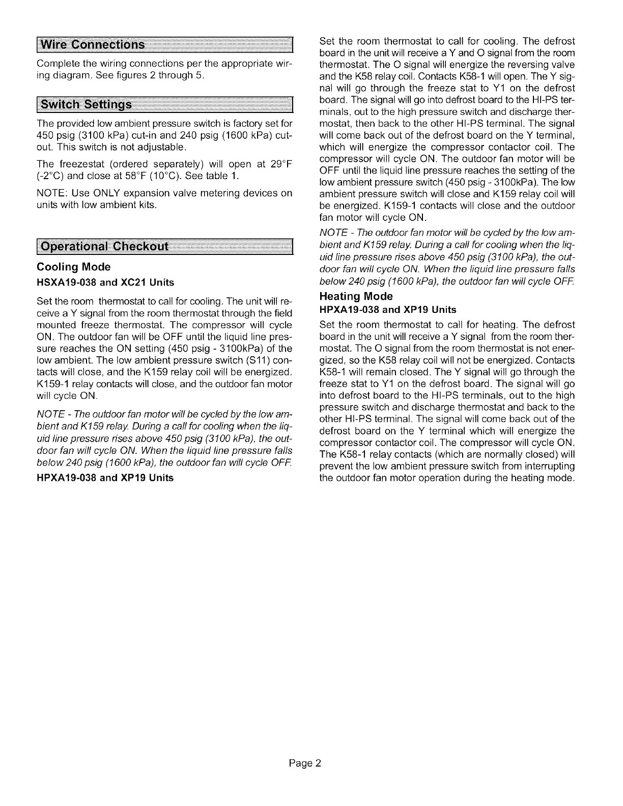
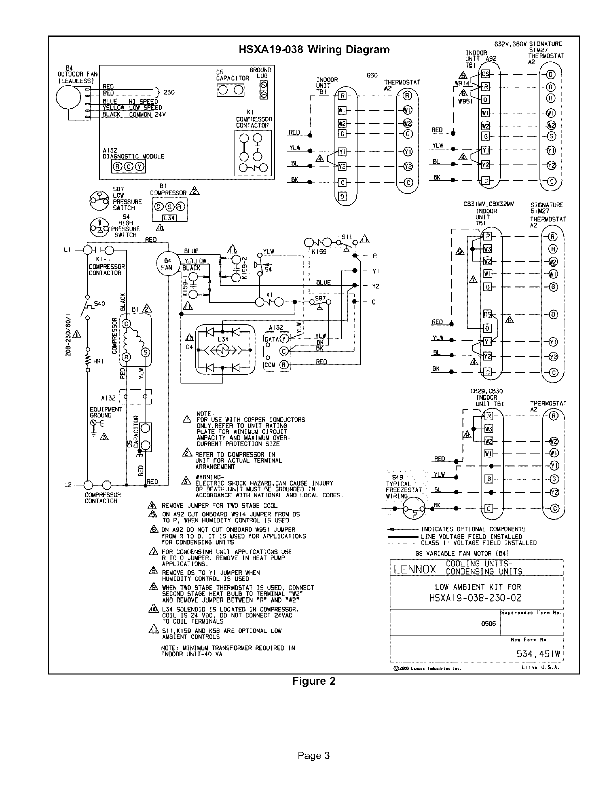
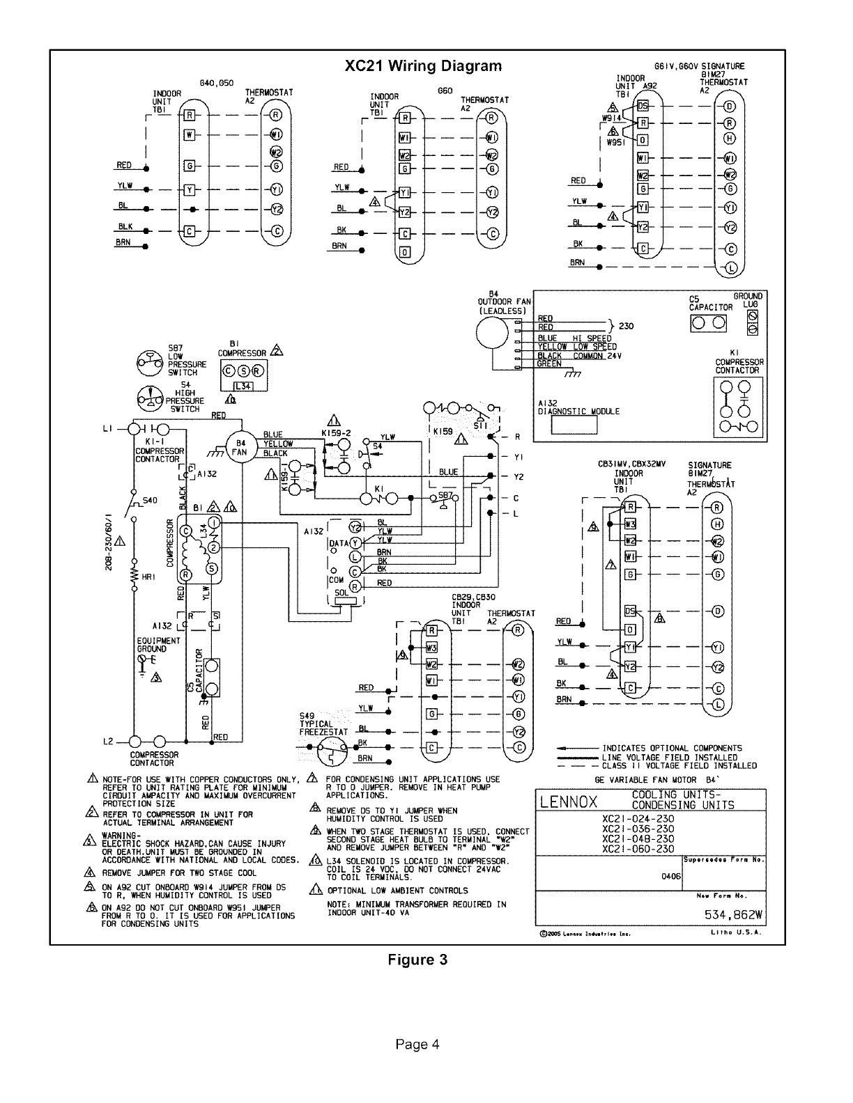
Complete the wiring connections per the appropriate wir-
ing diagram. See figures 2 through 5.
The provided low ambient pressure switch is factory set for
450 psig (3100 kPa) cut-in and 240 psig (1600 kPa) cut-
out. This switch is not adjustable,
The freezestat (ordered separately) will open at 29°F
(-2°C) and close at 58°F (10°C), See table 1,
NOTE: Use ONLY expansion valve metering devices on
units with low ambient kits.
Cooling Mode
HSXA19-038 and XC21 Units
Set the room thermostat to call for cooling, The unit will re-
ceive a Y signal from the room thermostat through the field
mounted freeze thermostat. The compressor will cycle
ON. The outdoor fan will be OFF until the liquid line pres-
sure reaches the ON setting (450 psig - 3100kPa) of the
low ambient. The low ambient pressure switch (S11) con-
tacts will close, and the K159 relay coil will be energized,
K159-1 relay contacts will close, and the outdoor fan motor
will cycle ON,
NOTE -The outdoor fan motor will be cycled by the low am-
bient and K159 relay. During a call for cooling when the liq-
uid line pressure rises above 450 psig (3100 kPa), the out-
door fan will cycle ON, When the liquid line pressure falls
below 240 psig (1600 kPa), the outdoor fan will cycle OFF.
HPXA19-038 and XP19 Units
Set the room thermostat to call for cooling. The defrost
board in the unit will receive a Y and O signal from the room
thermostat. The O signal will energize the reversing valve
and the K58 relay coil, Contacts K58-1 will open, The Y sig-
nal will go through the freeze stat to Y1 on the defrost
board. The signal will go into defrost board to the HI-PS ter-
minals, out to the high pressure switch and discharge ther-
mostat, then back to the other HI-PS terminal. The signal
will come back out of the defrost board on the Y terminal,
which will energize the compressor contactor coil. The
compressor will cycle ON. The outdoor fan motor will be
OFF until the liquid line pressure reaches the setting of the
low ambient pressure switch (450 psig - 3100kPa). The low
ambient pressure switch will close and K159 relay coil will
be energized. K159-1 contacts will close and the outdoor
fan motor will cycle ON,
NOTE -The outdoor fan motor will be cycled by the low am-
bient and K159 relay, During a call for cooling when the liq-
uid line pressure rises above 450 psig (3100 kPa), the out-
door fan will cycle ON, When the liquid line pressure falls
below 240 psig (1600 kPa), the outdoor fan will cycle OFF.
Heating Mode
HPXA19-038 and XP19 Units
Set the room thermostat to call for heating, The defrost
board in the unit will receive a Y signal from the room ther-
mostat, The O signal from the room thermostat is not ener-
gized, so the K58 relay coil will not be energized. Contacts
K58-1 will remain closed. The Y signal will go through the
freeze stat to Y1 on the defrost board. The signal will go
into defrost board to the HI-PS terminals, out to the high
pressure switch and discharge thermostat and back to the
other Ht-PS terminal. The signal will come back out of the
defrost board on the Y terminal which will energize the
compressor contactor coil, The compressor will cycle ON.
The K58-1 relay contacts (which are normally closed) will
prevent the low ambient pressure switch from interrupting
the outdoor fan motor operation during the heating mode,
Page 2
B4
OUTDOOR FAN
[LEAOLES5 }
LI
L2
HSXA19-038 Wiring Diagram
RED
RED _230
BLUE HI SPEED
YELLOW LOWSPEED
BLACK COMMON24V
A132
DIAGNOSTIC MODULE
C5 GROUND
CAPACITORF_ L_
KI
COMPRESSOR
CONTACTOR
SB7
PRESSURE
_ITCH
$4
_ HIGH
_:_3/PRESSURE
"_ SWITCH RED
MPRESSI
NTACTOI
40 Gl Z_
HRI _
F--
A132
OUIPMENT
;ROUND _;
-
i
COMPRESSOR
BI
COMPRESSOR /_
INDOOR
UNIT
TBI __
F---
[EF
YL-_ -- IZ_-
G60
THERMOSTAT
CONTACTOR
( )'.I"[.)-0-._O_ .r-. 511
BLUE /_ _YLW TKI59-- "K-'L R
YELLOW _'=--_ .'_ I _' --
TO-"[ I-.,-(_;k' I I- "'
.T= K_ L. __ _
A,32
D, I
NOTE-
Z_ FOR USE WITH COPPER CONDUCTORS
ONLY.REFER TO UNIT RATING
PLATE FOR MINIMUM CIRCUIT
AMPACITY AND MAXIMUM OVER-
CURRENT PROTECTION SIZE
-'_REFER TO COMPRESSOR IN
UNIT FOR ACTUAL TERMINAL
ARRANGEMENT
WARNING-
ELECTRIC SHOCK HAZARD,CAN CAUSE INJURY
OR DEATH.UNIT MUST BE GROUNDED IN
ACCORDANCE WITH NATIONAL AND LOCAL CODES.
Z_ REMOVE JUMPER FOR TWO STAGE COOL
•_ ON Ag2 CUT ONBOARD W91€ JUMPER FROM OS
TO R, WHEN HUMIDITY CONTROL IS USED
•_NON Ag2 DO NOT CUT ONBOARD wg51 JUMPER
FROM R TO 0. IT IS USED FOR APPLICATIONS
FOR CONDENSING UNITS
Z_ FOR CONDENSING UNIT APPLICATIONS USE
RTO 0 JUMPER, REMOVE IN HEAT PUMP
APPLICATIONS,
A:_ REMOVE OS TO YI JUMPER WHEN
HUMIDITY CONTROL IS USED
WHEN TWO STAGE THERMOSTAT 15 USED, CONNECT
SECOND STAGE HEAT BULB TO TERMINAL "W2"
AND REMOVE JUMPER BETIEEN "R" AND "W2"
____L34 SOLENOID IS LOCATED IN COMPRESSOR,
COIL IS 24 VOC, 00 NOT CONNECT 2_VAC
TO COIL TERMINALS.
A%SII,KI59 AND KSB ARE OPTIONAL LOW
AMBIENT CONTROLS
NOTE= MINIMUM TRANSFORMER REQUIRED IN
INDOOR UNIT-€O VA
Figure 2
G32V,G60V SIGNATURE
INDOOR
UNIT A92
TBI ,_
W951 []
I B_]]-
El-'
_----.-__ _
51M27
THERMOSTAT
A2 _,
®
CB31MV,CBX32MV SIGNATURE
INDOOR 51M27
UNIT THERMOSTAT
TBI A2
---,_-_
F-
_ -{_-- .-@
-@
A
RED -4_
YLW 41-
BL 4_ _
BK 41-
IN-.
CB29,CBJO
INDOOR
UNIT TBI
Nt-
Nt-
N-
I
RED .,ll-J
s_g
TYPICAL
FREEZESTAT __ __
i -- --
m -- --
m -- --
-@
THERMOSTAT
AZ _
_INDICATES OPTIONAL COMPONENTS
_LINE VOLTAGE FIELD INSTALLED
-- -- --CLASS II VOLTAGE FIELD INSTALLED
GE VARIABLE FAN MOTOR (Be)
COOLING UNITS-
LENNOX CONDENSING UNITS
LOWAMBIENT KIT FOR
HSXAIg-OGB-230-02
Supersedes Form No,
0506
Ne_ For_ No.
554,45 IW
(_)gO06L_a_x la_u=_,l_= In©. LI fho U, S, A.
Page 3
I
RED -6
YLW
BL 41-
BLK
BRN •
64-0,850
INDOOR THERMOSTAT
UNIT FAZ _,
TBI
r ..... -@ t
IN- .... -@1
@ .... -@1
---- .... --@1
--- --,-0t
XC21 Wiring Diagram
66O
INDOOR THERMOSTAT
RED ._ --I--(G) I
YLW 41- --I-_ 1
BRN 41 I-_l /v
587
Q OW
PRESSURE
SWITCH
5€
O HIGH
PRESSURE
SWITCH RIO
L' _ON_K_ _ _F__jAI32
_/Z__s4o B_,'_
'l
HRI )
F'f--
Ai_2 L_ __
ZDUIP_ ENT
BROU_{
t
r
L2_ _ )
COMPRESSOR
CONTACTOR
BI
COMPRESSOR L_
Be
OUTDOOR FAN
(LEADLESS)
J
J
BLUE K IB9_..2 _ YLW ,K!59 _ kR
I c'J l... I BLOEI ""
I_ _B_o
----J J UNIT THERMOSTAT
tN- ..... -@l
I__ ..... -@l
RE_D eFJ
r- ---.... -@ i
s_ _ [E]-..... -@I
TYPICAL
FREEZESTAT _ -- _ ..... _ I
/_k NOTE-FOR USE WITH COPPER CONDUCTORS ONLY, ,_ FOR CONDENSING UNIT APPLICATIONS USE
REFER TO UNIT RATING PLATE FOR MINIMUM R TO 0 JUMPER, REMOVE IN HEAT PUMP
CIRDUIT AMPACITY AND MAXIMUM OVERCURRENT APPLICATIONS.
PROTECTION SIZE "_ REMOVE DS TO YI JUMPER IHEN
•_REFER TO COMPRESSOR IN UNIT FOR
ACTUAL TERMINAL ARRANGEMENT HUMIDITY CONTROL IS USED
_k _IHEN TWO STAGE THERMOSTAT IS USED, CONNECT
/_ WARNING- SECOND STAGE HEAT BULB TO TERMINAL "V/2"
ELECTRIC SHOCK HAZARD,CAN CAUSE INJURY AND REMOVE JUMPER BETWEEN "R" AND "12"
OR DEATH,UNIT MUST BE GROUNDED IN
ACCOROANCE IITH NATIONAL AND LOCAL CODES, /(_k L3€ SOLENOID IS LOCATED IN COMPRESSOR.
./4k REMOVE JUMPER FOR TWO STAGE COOL COIL IS 2€ VDC, DO NOT CONNECT 24VAC
TO COIL TERMINALS.
-_ ON Ag2 CUT ONBOARO W914 JUMPER FROM DS i'k OPTIONAL LOW AMBIENT CONTROLS
TO R, WHEN HUMIDITY CONTROL IS USED
/_, ON A92 DO NOT CUT ONBOARD W951 JUMPER NOTE= MINIMUM TRANSFORMER REQUIRED IN
FROM R TO O. IT IS USED FOR APPLICATIONS INDOOR UNIT-40 VA
FOR CONDENSING UNITS
Figure 3
G61 V, G60V SIGNATURE
81MO7
INDOOR THERMOSTAT
UNIT A92 A2
TBI
I,Gs,_ ®1
I _ _'_
--Co)I
YLW : _ --@I
RED } 230
RED
BLUE HI SPEED
YELLOW LOW SREED
BLACK COMMON 2¢V
GREEN
--------Hn
C5 6ROUND
CAPACITOR___ L_
KI
COMPRESSOR
CONTACTOR
I
I
CBSIMV, CBX32MV SIGNATURE
INDOOR B IM27
UNIT TRERk_ST_T
TB IA2
,_-_ ®1
L_ -------@ I
I [] ----e i
I '_ [] --------@ I
[] --_---0 I
_r----@l ,-@)
-,e---------INDICATES OPTIONAL COMPONENTS
_LINE VOLTAGE FIELD INSTALLED
-- -- --CLASS II VOLTAGE FIELD INSTALLED
GE VARIABLE FAN MOTOR B$'
COOLING UNITS-
LENNOX CONDENSING UNITS
xc2_-o_-2so
xc2_-os6-_so
xcz_-o_e-zso
xcz_-o6o-zso
0406 Su_erlede_ F°r_ N_*
No_ Form No,
554,862W
Page 4
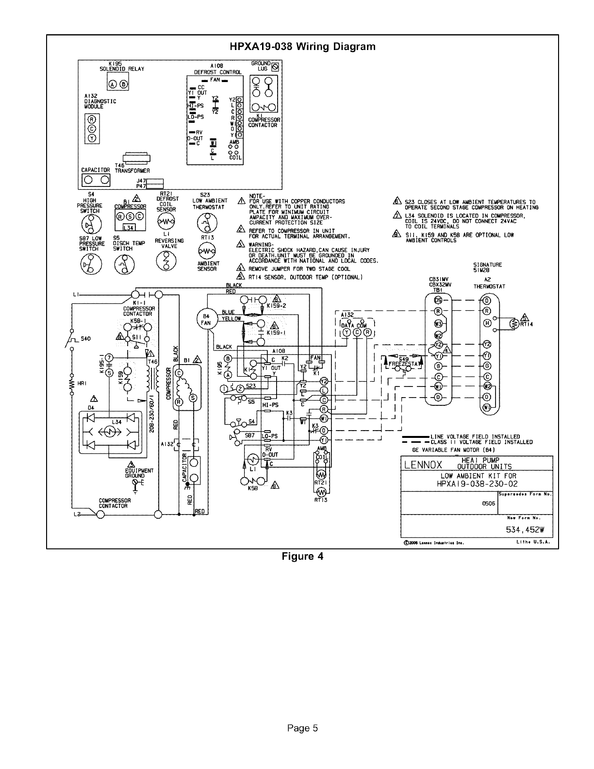
HPXA19-038 Wiring Diagram
KIDS
SOLENOID RELAY
AI32
OIABNOSTIC
MORULE
TAS_
CAPACITOR TRANSFORMER
$4 RT21 SZ5
PRESSURE COIL
SWITCH SENSOR THERMOSTAT
© L®
587 LOW $5 RTI 3
PRESSURE OISCH TEMP REVERSING
SWITCH SWITCH VALVE
_ _ _ ANBIENTSENSOR_
L, COMPRESSOR
CONTACTOR
(
I--5€0
EOUIPMENT
GROUND
COMPRESSOR
CONTACTOR
DE_OST CONTROL
n FAN_
E CC
YI OUT
-*
CO
L=_-PS R 0
_RV
3-OUT
COIL
OR_
A
v v
:o_ESSl
;ONTACTOf
NOTE-
A_ FOR USE WITH COPPER CONDUCTORS
ONLY.REFER TO UNIT RATING
PLATE FOR MINIMUM CIRCUIT
AMPACITY AND UAXI_JM OVER-
CURRENT PROTECTION SIZE
A
REFER TO COMPRESSOR IN UNIT
FOR ACTUAL TERMINAL ARRANGEMENT.
/_k WARNING-
ELECTRIC SHOCK HAZARD,CAN CAUSE INJURY
OR DEATH.UNIT MUST BE GROUNDED IN
ACCORDANCEWITH NATIONAL AND LOCAL CODES.
REMOVE JUMPER FOR _STAOE COOL
RTI4 SENSOR, OUTDOORTEMP (OPTIONAL)
BLACK
RED
RTI5
A
•B_ £23 CLOSES AT LOW AMBIENT TEMPERATURES TO
OPERATE SECONDSTABE COUPRESSORON HEATIND
/_ LSA SOLENOID IS LOCATED IN COMPRESSOR,
COIL IS 24VOC, DO NOT CONNECT 2AVAC
TO COIL TERMINALS
SII, K159 AND K58 ARE OPTIONAL LOW
ANBIENT CONTROLS
SIGNATURE
51U28
CB51MV A2
CBX32MV THERMOSTAT
TBI Nh
.....ii
(uir
0- ®
.4)- -Q
÷
--LINE VOLTARE FIELD INSTALLED
-- -- --CLASS II VOLTARE FIELD INSTALLED
6E VARIABLE FAN MOTOR (B4)
HEAi PUMP
LENNOX OUTDOOR UNITS
LOW AMBIENT KIT FOR
HPXAI 9-038-230-02
OSOG !Super$*_*s Fo_= No
Ntw F_m No.
534-, 452'//
(_;{_06 _.t_nll Intullflll In=. LIth_ U.S.A.
Figure 4
Page 5
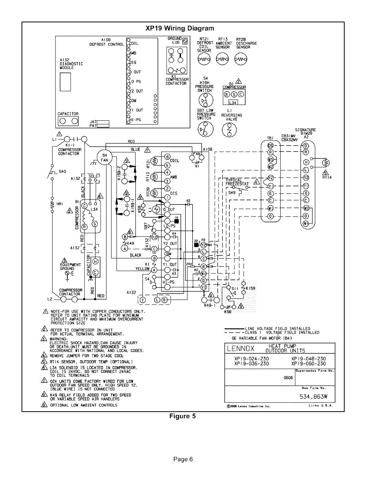
XP19 Wiring Diagram
A132
DIAGNOSTIC
MODULE
CAPACITOR
J,_7_
P47[ZZZ]
AI08
DEFROST CONTROL c(_OIL GROUNDI-_
LUG
(_OUT
_oPs COM%ESSOR
CONTACTOR
0
(_2 OUT °
OM 0
0
o°Y,OUT
,PS
RT21 RT I5 RT2B
DEFROST AMBIENT DISCHARGE
COIL SENSOR SENSOR
SENSOR
@@@
$4
HIGH BI L_
PRESSURE COMPRESSOR
SWITCH
$87 LOW k I
PRESSURE REVERSING
SWITCH VALVE
©@
II
HR, B'fA66111
, _I_ L_AIII
_X AI5
EOUIPMENT I _I _ 1 I
COMPRESSORI _ I I
_,_TA_RJ "IREDI
LZ _ --
RED
BLUE Z_
^ N .,-.FT--(_
/9_ /_ E:(,_ _.DIS
oOUT
L_ NOTE-FOR USE WITH COPPER CONDUCTORS ONLY.
REFER TO UNIT RATING PLATE FOR MINIMUM
CIRCUIT AMPACITY AND MAXIMUM OVERCURRENT
PROTECTION SIZE
/_ REFER TO COMPRESSOR IN UNIT
FOR ACTUAL TERMINAL ARRANGEMENT.
/_ WARNING-
ELECTRIC SHOCK HAZARD,CAN CAUSE INJURY
OR DEATH.UNIT MUST BE GROUNDED IN
ACCORDANCE WITH NATIONAL AND LOCAL CODES,
A
/¢X REMOVE JUMPER FOR TWO STAGE COOL
RTI¢ SENSOR, OUTDOOR TEMP (OPTIONAL)
•_ L3€ SOLENOID IS LOCATED IN COMPRESSOR,
COIL IS Z4VDC, DO NOT CONNECT Z4VAC
TO COIL TERMINALS
L_ OZ¢ UNITS COME FACTORY WIRED FOR LOW
OUTDOOR FAN SPEED ONLY, HIGH SPEED Y2,
(BLUE WIRE) IS NOT CONNECTED
K4g RELAY FIELD ADDED FOR TWO SPEED
OR VARIABLE SPEED AIR HANDLERS
L_ OPTIONAL LOW AMBIENT CONTROLS
08
KI
I
r 17y_c_-
ifFREEZESTAT
I_-_o--- -
I ISA__
K_ lllr ....
_h IIII r-----
lllllr-
Iiiii ----
I
I II I I
--_ i Iii I
l_Tx. J!II I ,
|II_ _ II_ i I
IJqll
I _,_ ___ ___ .i_J 7
z4v 4''v' I I'
I d_.._- I__J_J II
L_U_J.
Ir_"_sl-I _KI59
K58
SIGNATURE
CB31MV 81MZB
A2
RTI4
@
®
©
)
_LINE VOLTAGE FIELD INSTALLED
.... CLASS I VOLTAGE FIELD INSTALLED
GE VARIABLE FAN MOTOR (B4)
LENNOX HEAT PUMP
OUTDOOR UNITS
XP 19-024-230 XP I 9-048-230
XP 19-036-230 XP 19-060-2.50
0606 [S_w,r_,e_ Form No,
1
New Form NO,
554,863W
(_20_ L*_X Ifl_Ilrt@l I_¢. Lit_o U,S*A.
Figure 5
Page 6
