LENNOX Controls And HVAC Accessories Manual L0806365
User Manual: LENNOX LENNOX Controls and HVAC Accessories Manual LENNOX Controls and HVAC Accessories Owner's Manual, LENNOX Controls and HVAC Accessories installation guides
Open the PDF directly: View PDF ![]() .
.
Page Count: 2
,t_ 1993 Lennox industries Inc.
Dallas, Texas, USA
HEAT PUMPS
KITS AND ACCESSORIES
_pu echnica
blication
Lithe U.S.A.
502,826M
5/93
Supersedes 1/93
FM21 TMHEAT PUMP CONTROL
SLC1 SERVICE LIGHT KI'I"
INSTALLATION INSTRUCTIONS FOR SERVICE LIGHT OPTION FOR USE WITH
LENNOX FM21 TMSYSTEM
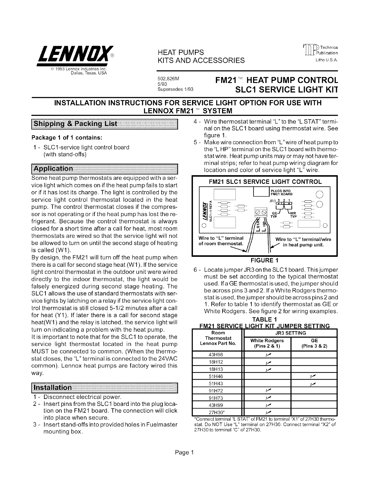
4 - Wire thermostat terminal "L" to the '%STAT" termi-
nal on the SLC1 board using thermostat wire. See
figure 1.
5 - Make wire connection from "L" wire dheat pump to
the "L HP" terminal on the SLC1 board with thermo-
stat wire, Heat pump units may or may not have ter-
minal strips; refer to heat pump wiring diagram for
location and color of service light "L" wire.
Package 1 of 1 contains:
1-SLCl-service light control board
(with stand-offs)
Some heat pump thermostats are equipped with a ser-
vice light which comes on if the heat pump fails to start
or if it has lost its charge. The light is controlled by the
service light control thermostat located in the heat
pump, The control thermostat closes if the compres-
sor is not operating or if the heat pump has lost the re-
frigerant, Because the control thermostat is always
closed for a short time after a call for heat, most room
thermostats are wired so that the service light will not
be allowed to turn on until the second stage of heating
is called (W1).
By design, the FM21 will turn off the heat pump when
there is a call for second stage heat (W1). If the service
light control thermostat in the outdoor unit were wired
directly to the indoor thermostat, the light would be
falsely energized during second stage heating, The
SLC 1 allows the use of standard thermostats with ser-
vice lights by latching on a relay if the service light con-
trol thermostat is still closed 5-1/2 minutes after a call
for heat (Y1). If later there is a call for second stage
heat(W1 ) and the relay is latched, the service light will
turn on indicating a problem with the heat pump,
It is important to note that for the SLC1 to operate, the
service light thermostat located in the heat pump
MUST be connected to common. (When the thermo-
stat closes, the "L" terminal is connected to the 24VAC
common). Lennox heat pumps are factory wired this
way.
1 - Disconnect electrical power,
2 - Insert pins from the SLC1 board into the plug loca-
tion on the FM21 board. The connection will click
into place when secure.
3 - Insert stand-offs into provided holes in Fuelmaster
mounting box.
FM21 SLC1 SERVICE LIGHT CONTROL
I I PLucs'"T° (_
FMC1 BOARD
L#_#
&4,/I rj _ _ TYP TYP
Wireto L terminal // It Wire to "L" terminal/wire
of room therm_/ !_ in heat pump unit
FIGURE 1
6 - Locate jumper JR3 on the SLC1 board. This jumper
must be set according to the typical thermostat
used. Ifa GE thermostat is used, the jumper should
be across pins 3 and 2. Ifa White Rodgers thermo-
stat is used, the jumper should be across pins 2 and
1. Refer to table 1 to identify thermostat as GE or
White Rodgers. See figure 2 for wiring examples.
TABLE 1
FM21 SERVICE LIGHT KIT JUMPER SETTING
Room
Thermostat
Lennox Part No•
JR3 SETTING
WhiteRodgers
(Pins 2 & 1)
p,,
p,,
p,,
GE
(Pins 3 & 2)
43H98
18H12
18H13
51 H46
51 H43
91 H72
91 H73
43H99
27H30"
*Connect terminal 'L STAT" of FM21 to terminal "Xl" of 27H30 thermo-
stat. Do NOT Use 'L" terminal on 27H30. Connect terminal 'X2" of
27H30 to terminal 'C" of 27H30.
Page 1
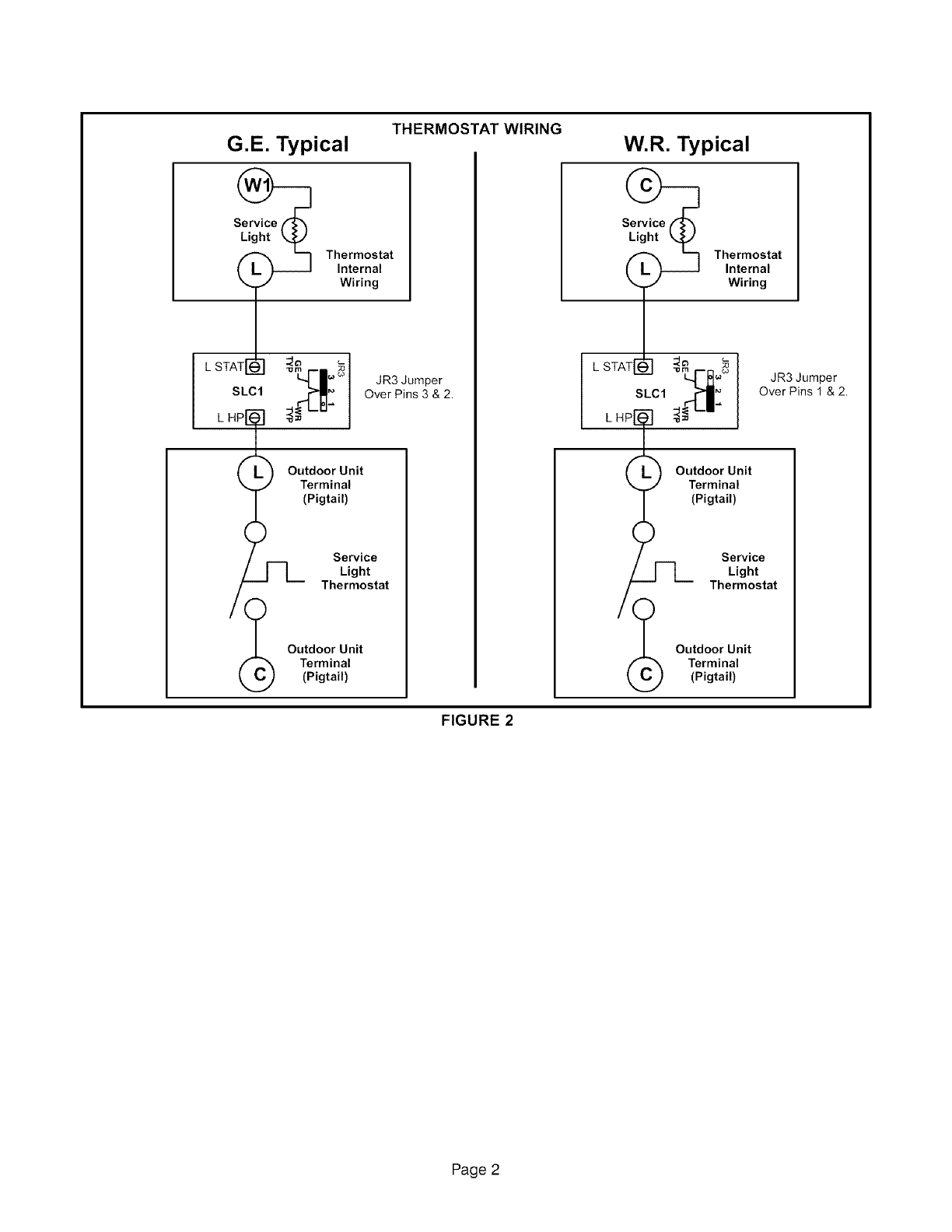
G.E. Typical THERMOSTAT WIRING
Thermostat
Internal
Wiring
STATrFL_ _
L•'sm ;o
s,c,
H(_P[_ Outdoor Unit
L
Terminal
(Pigtail)
JR3 Jumper
Over Pins 3 & 2.
Service
Light
Thermostat
_Outdoor Unit
Terminal
(Pigtail)
W.R. Typical
Thermostat
Internal
Wiring
STATi2 _
L
SLCl
k
H Outdoor Unit
Terminal
(Pigtail)
JR3 Jumper
Over Pins 1 & 2.
Service
Light
Thermostat
Outdoor Unit
Terminal
(Pigtail)
FIGURE 2
Page 2
