LENNOX Furnace/Heater, Oil Manual L0806374
User Manual: LENNOX LENNOX Furnace/Heater, Oil Manual LENNOX Furnace/Heater, Oil Owner's Manual, LENNOX Furnace/Heater, Oil installation guides
Open the PDF directly: View PDF ![]() .
.
Page Count: 18
zEA, vO. .
,t_2005 Lennox Industries Inc,
Dallas, Texas, USA
INSTALLATION
INSTRUCTIONS
025 SERIES UNITS
OIL UNITS _ Technical
505,149M .LLJJ. Publications
38152A075
12/2005 Litho U.S.A.
General ..................................... 1
Shipping & Packing .......................... 1
025 Unit Dimensions ......................... 2
025 Unit Parts Arrangement ................... 3
025 Riello Oil Burner Parts Arrangement ........ 3
Locate & Level the Unit ....................... 4
Unit Set-Up .................................. 4
Requirements ................................ 6
Venting ..................................... 9
Flue Connections ........................... 10
Supply & Return Air Plenums ................. 12
Oil Supply Piping ............................ 12
Leak Check ................................ 14
Electrical Wiring ............................. 15
Pump Purging .............................. 16
Unit Start-Up & Adjustments .................. 16
Service .................................... 17
025 Start-Up & Performance Check List ....... 18
,A, CAUTION
RETAIN THESE INSTRUCTIONS
FOR FUTURE REFERENCE
,_, WARNING
These instructions are intended as a general guide and do
not supersede local codes in any way, Only qualified tech-
nicians can install and service the Lennox Elite® Series
025 oil furnaces. In Canada, refer to CSA B139 for recom-
mended installation procedures, Consult authorities who
have jurisdiction before installation.
Ak CAUTION
,_, WARNING
12/05
IIIH]IIIIIIIIIIIIIIIIIHIIIIIIIIIIIII Page
1 - Assembled oil furnace
1 - Barometric draft control
1 - Bypass plug (used on two oil line lift systems)
1 - Side filter adapter kit (includes filter)
1 - Return line adapter
Check the components for shipping damage. If you find
any damage, immediately contact the last carrier.
505,149 M
1 IIIllllllllllllllll]llllllHIIIII]llllllll
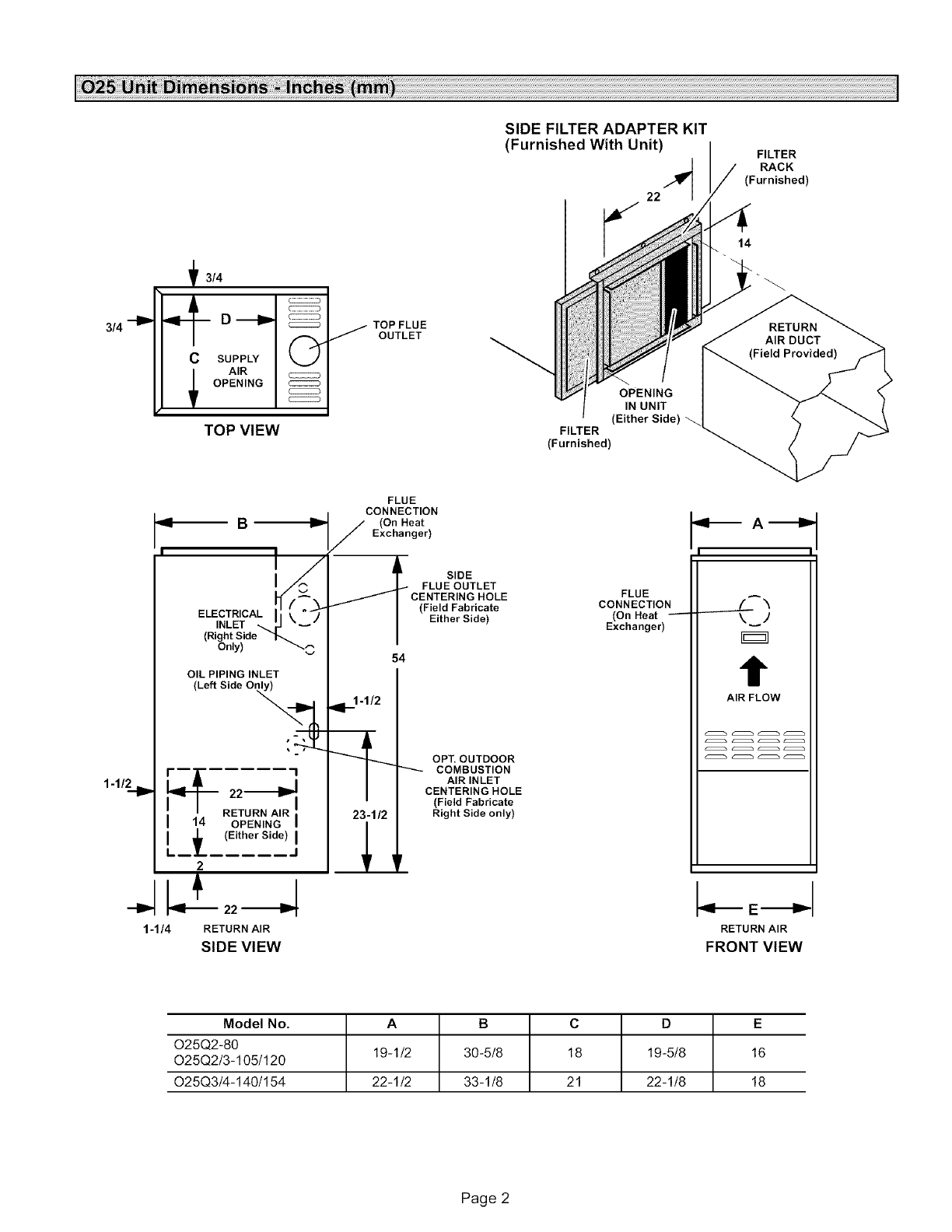
SIDE FILTER ADAPTER KIT
(Furnished With Unit) / FILTER
RACK
(Furnished)
3/4 --IP
f3/4
D_
C SUPPLY (_
AIR
OPENING
TOP VIEW
TOP FLUE
J OUTLET
OPENING
IN UNIT
(Either Side)
FILTER
(Furnished)
14
1-1/_1 P
1-1/4
B
ELECTR,CALi"
INLET _ _J
(Right Side "_
Only) _
OIL PIPING INLET
(Left Side Only)
_22----_
RETURN AIR
I 14 OPENING
I _ (Either Side)
L--L ..... J
2
RETURN AIR
SIDE VIEW
FLUE
CONNECTION
J(On Heat
Exchanger)
SIDE
FLUE OUTLET
CENTERING HOLE
(Field Fabricate
Either Side)
54
91_1-1/2
23-1/2
OPT. OUTDOOR
COMBUSTION
AIR INLET
CENTERING HOLE
(Field Fabricate
Right Side only)
FLUE
CONNECTION
(On Heat
Exchanger)
I I
t
AIR FLOW
RETURN AIR
FRONT VIEW
Model No. A B C D E
025Q2-80 19-1/2 30-5/8 18 19-5/8 16
025Q2/3-105/120
025Q3/4-140/154 22-1/2 33-1/8 21 22-1/8 18
Page 2
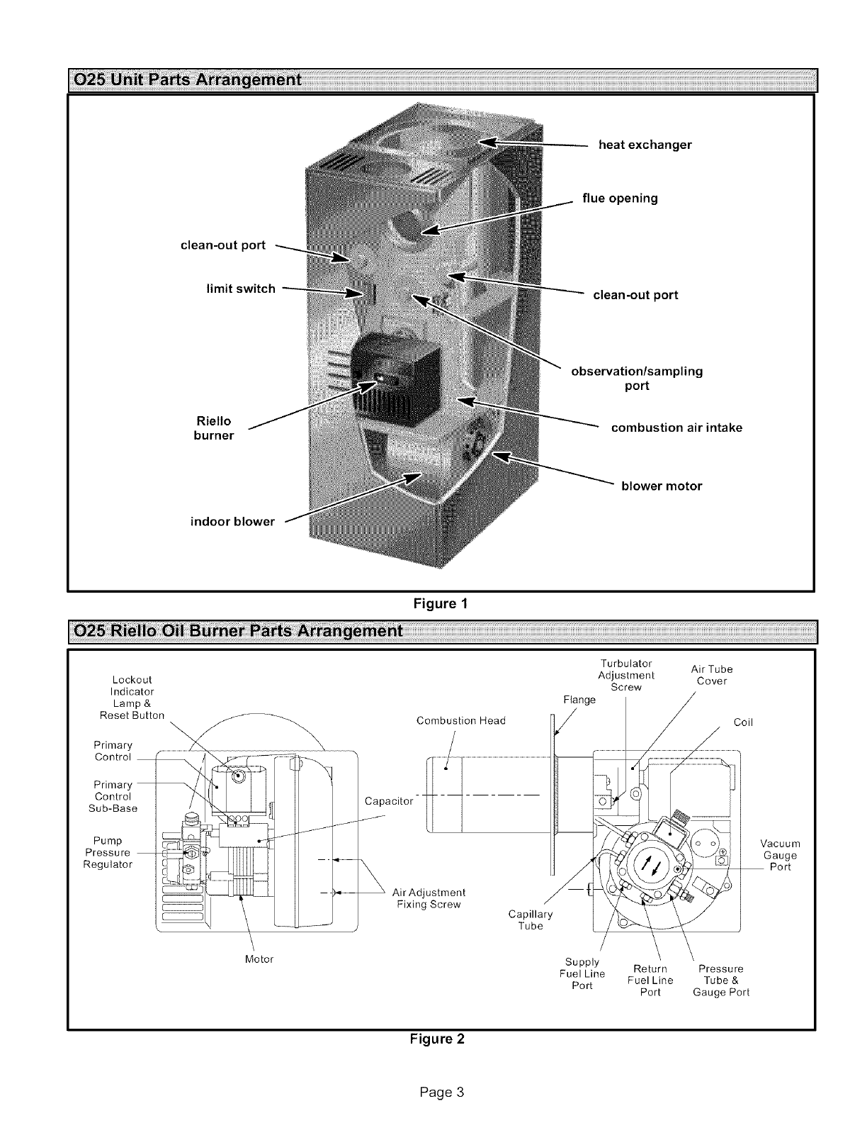
heatexchanger
flue opening
clean-out port
limit switch clean-out port
Riello
burner
observation/sampling
port
combustion air intake
blower motor
indoor blower
Figure 1
Turbulator
Lockout Adjustment
Indicator Screw
Lamp & Flange
Reset Button Combustion Head
Primary
Control
Air Tube
Cover
Coil
Primary,
Control Capacitor - -
Sub-Base
Pump
Pressure
Regulator
Air Adjustment
Fixing Screw Capillary
Tube
Vacuum
Gauge
Port
Motor Supply
Fuel Line Return Pressure
Port Fuel Line Tube &
Port Gauge Port
Figure 2
Page 3
1- Settheunitin desiredlocationkeepingin mindthe
clearanceslistedintable2,Alsokeepinmindoilsup-
ply connections,electricalsupply,flue connections
andsufficientclearancefor installingandservicing
unit,
2 - Leveltheunitfromsidetosideandfromfronttorear.If
thefurnaceis not level,placefireproofwedgesor
shimsbetweenthelowsideof the furnaceandthe
floor.Makesuretheweightofthefurnaceisdistributed
evenlyonallfourcorners,Strainon sidesof cabinet
causingcrackingand poppingnoisesmayoccurif
weightoffurnaceisnotevenlydistributed.
WARNING
Input Selection
1 - Determine the desired furnace firing rate, Use table 1
to select the proper nozzle and pump pressure required
to obtain the desired input from the burner, tf necessary,
replace the nozzle to achieve the higher input rate.
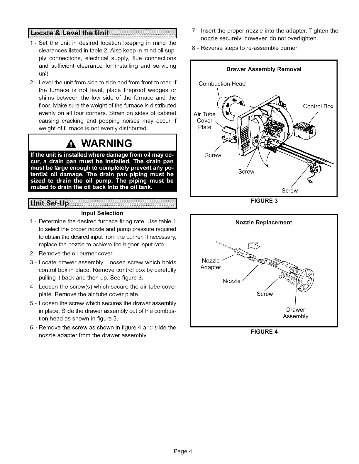
2- Remove the oil burner cover.
3 - Locate drawer assembly. Loosen screw which holds
control box in place, Remove control box by carefully
pulling it back and then up, See figure 3,
4 - Loosen the screw(s) which secure the air tube cover
plate, Remove the air tube cover plate,
5 - Loosen the screw which secures the drawer assembly
in place. Slide the drawer assembly out of the combus-
tion head as shown in figure 3.
6 - Remove the screw as shown in figure 4 and slide the
nozzle adapter from the drawer assembly.
7 - Insert the proper nozzle into the adapter. Tighten the
nozzle securely; however, do not overtighten.
8 - Reverse steps to re-assemble burner.
Drawer Assembly Removal
Combustion Head
/
Air Tube
Cover
Plate
Control Box
/
/
Screw
Screw
Screw
FIGURE 3
Nozzle Replacement
Nozzle _ __-__
Adapter /_... ':'_
Nozzle/Sc ___
Drawer
Assembly
FIGURE 4
Page 4
Furnace
Model
801
105/1201
105/1202
140/1541
140/1542
Riello
Burner
Model
F3
F3
F3
F5
F5
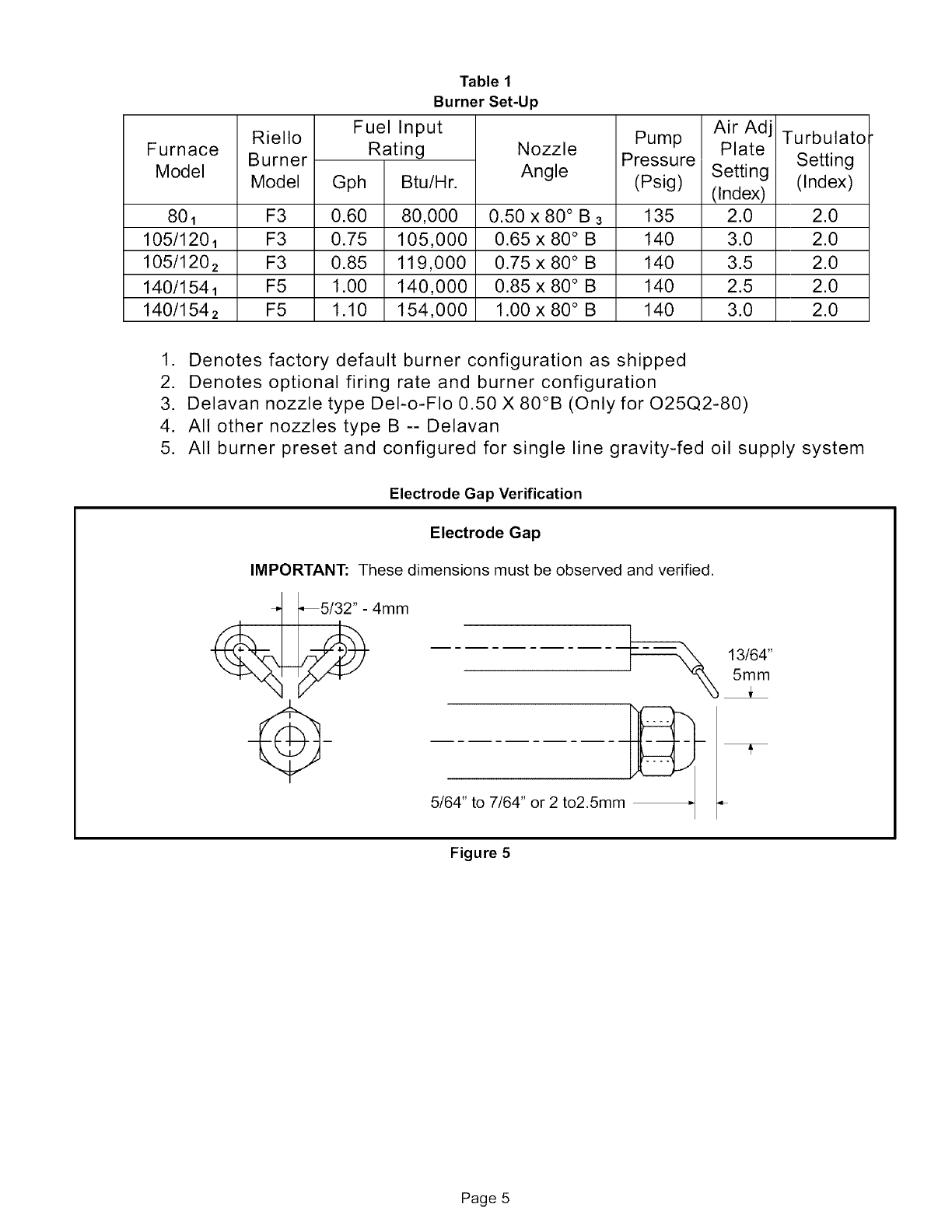
Table 1
Burner Set-Up
Fuel Input
Rating
Gph Btu/Hr.
0.60 80,000
0.75 105,000
0.85 119,000
1.00 140,000
1.10 154,000
Nozzle
Angle
0.50 x 80 ° B 3
0.65 x 80 ° B
0.75 x 80 ° B
0.85 x 80 ° B
1.00 x 80 ° B
Pump
Pressure
(Psig)
135
140
140
140
140
Air Adj
Plate
Setting
(Index)
2.0
3.0
3.5
2.5
3.0
Turbulato
Setting
(Index)
2.0
2.0
2.0
2.0
2.0
1. Denotes factory default burner configuration as shipped
2. Denotes optional firing rate and burner configuration
3. Delavan nozzle type Del-o-FIo 0.50 X 80°B (Only for O25Q2-80)
4. All other nozzles type B -- Delavan
5. All burner preset and configured for single line gravity-fed oil supply system
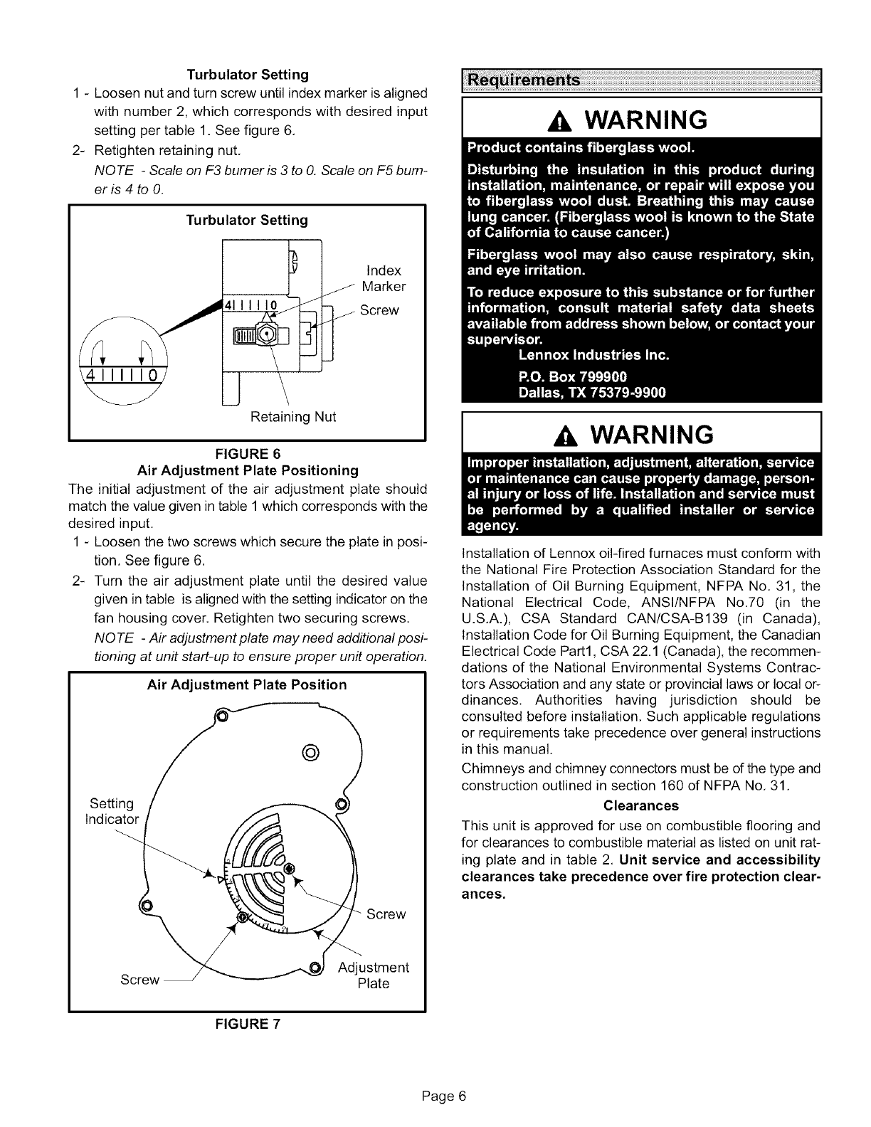
Electrode Gap Verification
Electrode Gap
IMPORTANT: These dimensions must be observed and verified.
4am
5/64" to 7/64" or 2 to2.5mm
13/64"
5mm
Figure 5
Page 5
TurbulatorSetting
1- Loosennutandturnscrewuntilindexmarkerisaligned
withnumber2,whichcorrespondswithdesiredinput
settingpertable1.Seefigure6,
2- Retightenretainingnut,
NOTE -Scale on F3 burner is 3 to O,Scale on F5 bum-
er is 4 to O,
\4111110J
Turbulator Setting
4--L_ j
J
Index
Marker
_ Screw
Retaining Nut
FIGURE 6
Air Adjustment Plate Positioning
The initial adjustment of the air adjustment plate should
match the value given in table 1 which corresponds with the
desired input,
1 - Loosen the two screws which secure the plate in posi-
tion. See figure 6.
2- Turn the air adjustment plate until the desired value
given in table is aligned with the setting indicator on the
fan housing cover, Retighten two securing screws,
NO TE -Air adjustment plate may need additional posi-
tioning at unit start-up to ensure proper unit operation,
Air Adjustment Plate Position
@
Setting
Indicator
Screw
Screw Adjustment
Plate
A WARNING
Ak WARNING
Installation of Lennox oil-fired furnaces must conform with
the National Fire Protection Association Standard for the
Installation of Oil Burning Equipment, NFPA No. 31, the
National Electrical Code, ANSI/NFPA No.70 (in the
U.S.A.), CSA Standard CAN/CSA-B139 (in Canada),
Installation Code for Oil Burning Equipment, the Canadian
Electrical Code Part1, CSA 22.1 (Canada), the recommen-
dations of the National Environmental Systems Contrac-
tors Association and any state or provincial laws or local or-
dinances. Authorities having jurisdiction should be
consulted before installation. Such applicable regulations
or requirements take precedence over general instructions
in this manual.
Chimneys and chimney connectors must be of the type and
construction outlined in section 160 of NFPA No. 31.
Clearances
This unit is approved for use on combustible flooring and
for clearances to combustible material as listed on unit rat-
ing plate and in table 2. Unit service and accessibility
clearances take precedence over fire protection clear-
ances,
FIGURE 7
Page 6
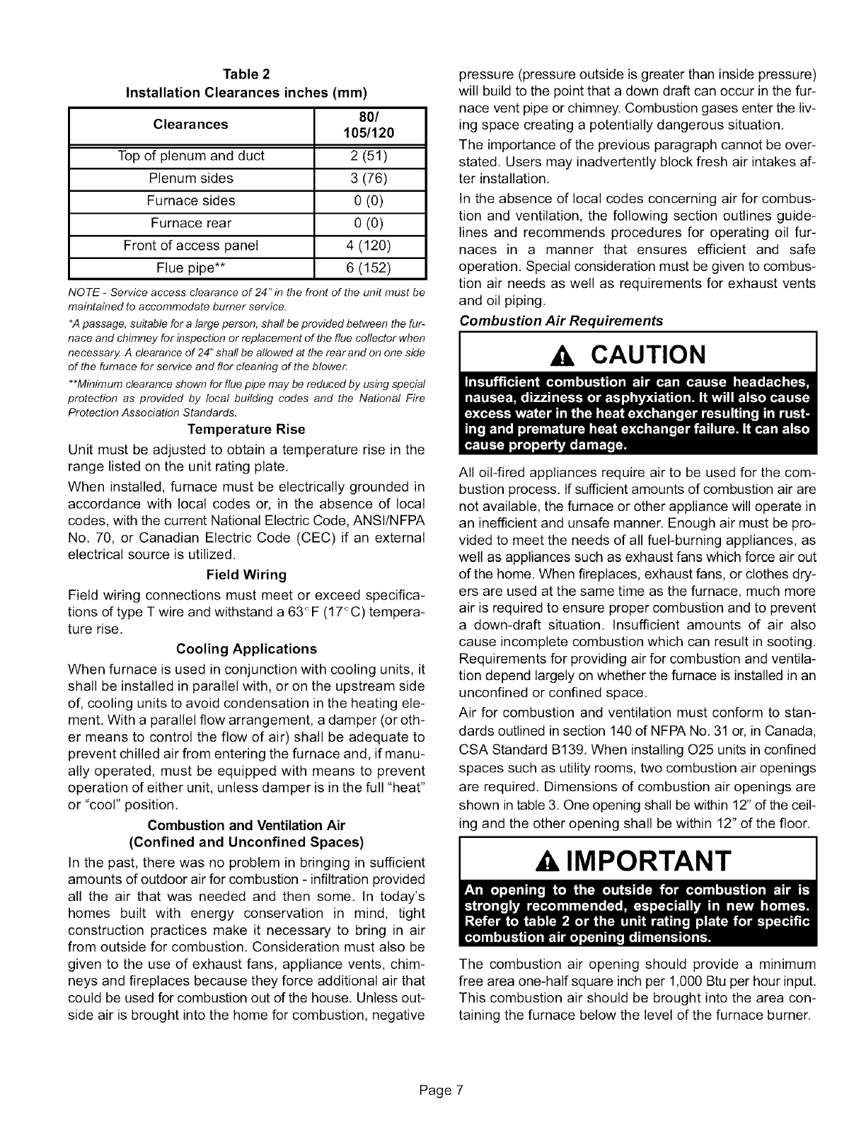
Table 2
Installation Clearances inches (mm)
Clearances 80/
105/120
Top of plenum and duct 2 (51)
Plenum sides 3 (76)
Furnace sides 0 (0)
Furnace rear 0 (0)
Front of access panel 4 (120)
Flue pipe** 6 (152)
NOTE -Service access clearance of 24" in the front of the unit must be
maintained to accommodate burner service.
*A passage, suitable for a large person, shaft be provided between the fur-
nace and chimney for inspection or replacement of the flue collector when
necessar_ A clearance of 24" shaft be allowed at the rear and on one side
of the furnace for service and flor cleaning of the blower.
**Minimum clearance shown forflue pipe may be reduced by using special
protection as provided by local building codes and the National Fire
Protection Association Standards.
Temperature Rise
Unit must be adjusted to obtain a temperature rise in the
range listed on the unit rating plate,
When installed, furnace must be electrically grounded in
accordance with local codes or, in the absence of local
codes, with the current National Electric Code, ANSI/NFPA
No. 70, or Canadian Electric Code (CEC) if an external
electrical source is utilized,
Field Wiring
Field wiring connections must meet or exceed specifica-
tions of type T wire and withstand a 63 <_F (17 <_C) tempera-
ture rise,
Cooling Applications
When furnace is used in conjunction with cooling units, it
shall be installed in parallel with, or on the upstream side
of, cooling units to avoid condensation in the heating ele-
ment. With a parallel flow arrangement, a damper (or oth-
er means to control the flow of air) shall be adequate to
prevent chilled air from entering the furnace and, if manu-
ally operated, must be equipped with means to prevent
operation of either unit, unless damper is in the full "heat"
or "cool" position,
Combustion and Ventilation Air
(Confined and Unconfined Spaces)
In the past, there was no problem in bringing in sufficient
amounts of outdoor air for combustion - infiltration provided
all the air that was needed and then some, In today's
homes built with energy conservation in mind, tight
construction practices make it necessary to bring in air
from outside for combustion, Consideration must also be
given to the use of exhaust fans, appliance vents, chim-
neys and fireplaces because they force additional air that
could be used for combustion out of the house, Unless out-
side air is brought into the home for combustion, negative
pressure (pressure outside is greater than inside pressure)
will build to the point that a down draft can occur in the fur-
nace vent pipe or chimney. Combustion gases enter the liv-
ing space creating a potentially dangerous situation,
The importance of the previous paragraph cannot be over-
stated, Users may inadvertently block fresh air intakes af-
ter installation,
In the absence of local codes concerning air for combus-
tion and ventilation, the following section outlines guide-
lines and recommends procedures for operating oil fur-
naces in a manner that ensures efficient and safe
operation. Special consideration must be given to combus-
tion air needs as well as requirements for exhaust vents
and oil piping,
Combustion Air Requirements
CAUTION
All oil-fired appliances require air to be used for the com-
bustion process. If sufficient amounts of combustion air are
not available, the furnace or other appliance will operate in
an inefficient and unsafe manner. Enough air must be pro-
vided to meet the needs of all fuel-burning appliances, as
well as appliances such as exhaust fans which force air out
of the home. When fireplaces, exhaust fans, or clothes dry-
ers are used at the same time as the furnace, much more
air is required to ensure proper combustion and to prevent
a down-draft situation. Insufficient amounts of air also
cause incomplete combustion which can result in sooting.
Requirements for providing air for combustion and ventila-
tion depend largely on whether the furnace is installed in an
unconfined or confined space.
Air for combustion and ventilation must conform to stan-
dards outlined in section 140 of NFPA No. 31 or, in Canada,
CSA Standard B139, When installing 025 units in confined
spaces such as utility rooms, two combustion air openings
are required. Dimensions of combustion air openings are
shown in table 3. One opening shall be within 12" of the ceil-
ing and the other opening shall be within 12" of the floor,
IMPORTANT
The combustion air opening should provide a minimum
free area one-half square inch per 1,000 Btu per hour input.
This combustion air should be brought into the area con-
taining the furnace below the level of the furnace burner.
Page 7
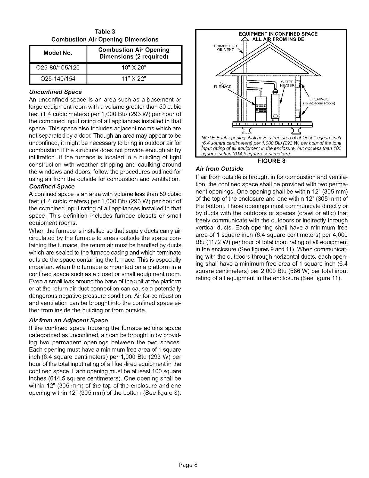
Table 3
Combustion Air Opening Dimensions
Model No. Combustion Air Opening
Dimensions (2 required)
O25-80/105/120 10" X 20"
O25-140/154 11"X 22"
Unconfined Space
An unconfined space is an area such as a basement or
large equipment room with a volume greater than 50 cubic
feet (1.4 cubic meters) per 1,000 Btu (293 W) per hour of
the combined input rating of all appliances installed in that
space. This space also includes adjacent rooms which are
not separated by a door. Though an area may appear to be
unconfined, it might be necessary to bring in outdoor air for
combustion if the structure does not provide enough air by
infiltration. If the furnace is located in a building of tight
construction with weather stripping and caulking around
the windows and doors, follow the procedures outlined for
using air from the outside for combustion and ventilation.
Confined Space
A confined space is an area with volume less than 50 cubic
feet (1.4 cubic meters) per 1,000 Btu (293 W) per hour of
the combined input rating of all appliances installed in that
space. This definition includes furnace closets or small
equipment rooms.
When the furnace is installed so that supply ducts carry air
circulated by the furnace to areas outside the space con-
taining the furnace, the return air must be handled by ducts
which are sealed to the furnace casing and which terminate
outside the space containing the furnace. This is especially
important when the furnace is mounted on a platform in a
confined space such as a closet or small equipment room.
Even a small leak around the base dthe unit at the platform
or at the return air duct connection can cause a potentially
dangerous negative pressure condition. Air for combustion
and ventilation can be brought into the confined space ei-
ther from inside the building or from outside.
Air from an Adjacent Space
If the confined space housing the furnace adjoins space
categorized as unconfined, air can be brought in by provid-
ing two permanent openings between the two spaces.
Each opening must have a minimum free area of 1 square
inch (6.4 square centimeters) per 1,000 Btu (293 W) per
hour of the total input rating of all fuel-fired equipment in the
confined space. Each opening must be at least 100 square
inches (614.5 square centimeters). One opening shall be
within 12" (305 mm) of the top of the enclosure and one
opening within 12" (305 mm) of the bottom (See figure 8).
CHIMNEY OR
OIL VENT
EQUIPMENT IN CONFINED SPACE
FROM INSIDE
OIL
FURNACE _.\
OPENINGS
(To Adjacent Room)
i,/
! ii ii ii ii ii ii ii ii !
| |
i I JL
NOTE-Each opening shall have a free area of at least ! square inch
(6.4 square centimeters) per !, 000 Btu (293 W) per hour of the total
input rating of all equipment in the enclosure, but not less than 100
square inches (6!4.5 square centimeters).
FIGURE 8
Air from Outside
If air from outside is brought in for combustion and ventila-
tion, the confined space shall be provided with two perma-
nent openings. One opening shall be within 12" (305 mm)
of the top of the enclosure and one within 12" (305 mm) of
the bottom. These openings must communicate directly or
by ducts with the outdoors or spaces (crawl or attic) that
freely communicate with the outdoors or indirectly through
vertical ducts. Each opening shall have a minimum free
area of 1 square inch (6.4 square centimeters) per 4,000
Btu (1172 W) per hour of total input rating of all equipment
in the enclosure (See figures 9 and 11). When communicat-
ing with the outdoors through horizontal ducts, each open-
ing shall have a minimum free area of 1 square inch (6.4
square centimeters) per 2,000 Btu (586 W) per total input
rating of all equipment in the enclosure (See figure 11).
Page 8
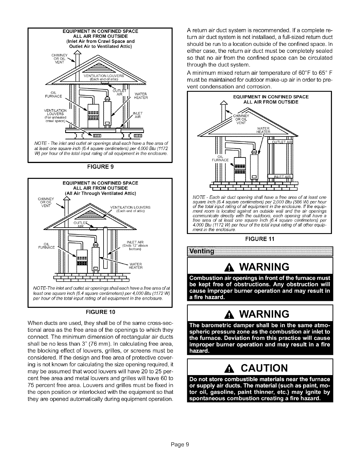
EQUIPMENT IN CONFINED SPACE
ALL AIR FROM OUTSIDE
(Inlet Air from Crawl Space and
Outlet Air to Ventilated Attic)
CHIMNEY
OR OIL "_
VENT
OIL WATER
FURNACE HEATER
VENTILATION
LOUVERS INLET
(Forunheated AIR
crawl 5
rrrm
r1r 1
NOTE -Theinlet and outlet air openings shaft each have a free area of
at least one square inch (6.4 square centimeters) per 4,000 Btu (1172
W) per hour of the total input rating of all equipment in the enclosure.
FIGURE 9
CHIMNEY
OR OIL
VENT
EQUIPMENT IN CONFINED SPACE
ALL AIR FROM OUTSIDE
(All Air Through Ventilated Attic)
VENTILATION LOUVERS
(Each end of attic)
INLET AIR
OIL (Ends 12" above
FURNACE bo{tom)
HEATER
NO TE-The inlet and outlet air openings shall each have a free area of at
least one square inch (6.4 square centimeters) per 4,000 Btu (1172 W)
per hour of the total input rating of all equipment in the enclosure.
FIGURE 10
When ducts are used, they shall be of the same cross-sec-
tional area as the free area of the openings to which they
connect. The minimum dimension of rectangular air ducts
shall be no less than 3" (76 mm). In calculating free area,
the blocking effect of louvers, grilles, or screens must be
considered. If the design and free area of protective cover-
ing is not known for calculating the size opening required, it
may be assumed that wood louvers will have 20 to 25 per-
cent free area and metal louvers and grilles will have 60 to
75 percent free area. Louvers and grilles must be fixed in
the open position or interlocked with the equipment so that
they are opened automatically during equipment operation.
A return air duct system is recommended. If a complete re-
turn air duct system is not installaed, a full-sized return duct
should be run to a location outside of the confined space. In
either case, the return air duct must be completely sealed
so that no air from the confined space can be circulated
through the duct system.
A minimum mixed return air temperature of 60°F to 65 ° F
must be maintained for outdoor make-up air in order to pre-
vent condensation and corrosion.
EQUIPMENT IN CONFINED SPACE
WATER
III IIII III II
III IIII III II
NOTE -Each air duct opening shaft have a free area of at least one
square inch (6.4 square centimeters) per 2,000 Btu (586 W) per hour
of the total input rating of all equipment in the enclosure, ff the equip-
ment room is located against an outside wall and the air openings
communicate directly with the outdoors, each opening shall have a
free area of at least one square inch (6.4 square centimeters) per
4,000 Btu (1172 W) per hour of the total input rating of all other equip-
ment in the enclosure.
FIGURE 11
WARNING
Ak WARNING
Ak CAUTION
Page 9
A, WARNING
NOTE -Oil burning equipment may be vented into an ap-
proved masonry chimney or type L vent. (Type L vent is
similar in construction to type B gas vent except it carries a
higher temperature rating and is constructed with an inner
finer of stainless steel rather than aluminum).
Prior to installation of unit, make a thorough inspection of
the chimney to determine whether repairs are necessary.
Make sure the chimney is properly constructed and sized
according to the requirements of the National Fire Protec-
tion Association. The smallest dimensions of the chimney
should be at least equal to the diameter of the furnace vent
connector. Make sure the chimney will produce a steady
draft sufficient to remove all the products of combustion
from the furnace. A draft of at least ,04" w,c, (9,9 Pa) is re-
quired during burner operation,
1 - Local building codes may have more stringent installa-
tion requirements and should be consulted before
installation of unit.
2 - The vent connector should be as short as possible to
do the job.
3 - The vent connector should not be smaller than the out-
let diameter of the vent outlet of the furnace,
4 - Pipe should be at least 24 gauge galvanized,
5 - Single wall vent pipe should not run outside or through
any unconditioned space.
6 - Chimney should extend 3 feet (0.9 m) above any flat
section of roof within a horizontal distance d10 feet (3
m). The chimney must also extend 2 feet (0.6 m)
above the highest roof peak within a horizontal dis-
tance of 10 feet (3 m).
7- The vent must not pass through a floor or ceiling.
Clearances to single wall vent pipe should be no less
than 6" (152 mm); more if local codes require it.
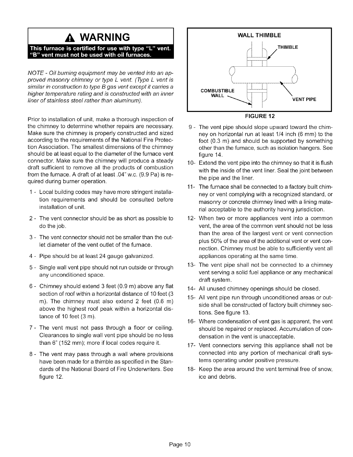
8 - The vent may pass through a wall where provisions
have been made for a thimble as specified in the Stan-
dards of the National Board of Fire Underwriters. See
figure 12.
WALL THIMBLE
THIMBLE
COMBUSTIBLE
WALL VENT PIPE
FIGURE 12
9 - The vent pipe should slope upward toward the chim-
ney on horizontal run at least 1/4 inch (6 mm) to the
foot (0.3 m) and should be supported by something
other than the furnace, such as isolation hangers. See
figure 14.
10- Extend the vent pipe into the chimney so that it is flush
with the inside of the vent liner. Seal the joint between
the pipe and the liner.
11- The furnace shall be connected to a factory built chim-
ney or vent complying with a recognized standard, or
masonry or concrete chimney lined with a lining mate-
rial acceptable to the authority having jurisdiction.
12- When two or more appliances vent into a common
vent, the area of the common vent should not be less
than the area of the largest vent or vent connection
plus 50% of the area of the additional vent or vent con-
nection. Chimney must be able to sufficiently vent all
appliances operating at the same time.
13- The vent pipe shall not be connected to a chimney
vent serving a solid fuel appliance or any mechanical
draft system.
14- All unused chimney openings should be closed.
15- All vent pipe run through unconditioned areas or out-
side shall be constructed of factory built chimney sec-
tions. See figure 13.
16- Where condensation of vent gas is apparent, the vent
should be repaired or replaced. Accumulation of con-
densation in the vent is unacceptable.
17- Vent connectors serving this appliance shall not be
connected into any portion of mechanical draft sys-
tems operating under positive pressure.
18- Keep the area around the vent terminal free of snow,
ice and debris.
Page 10
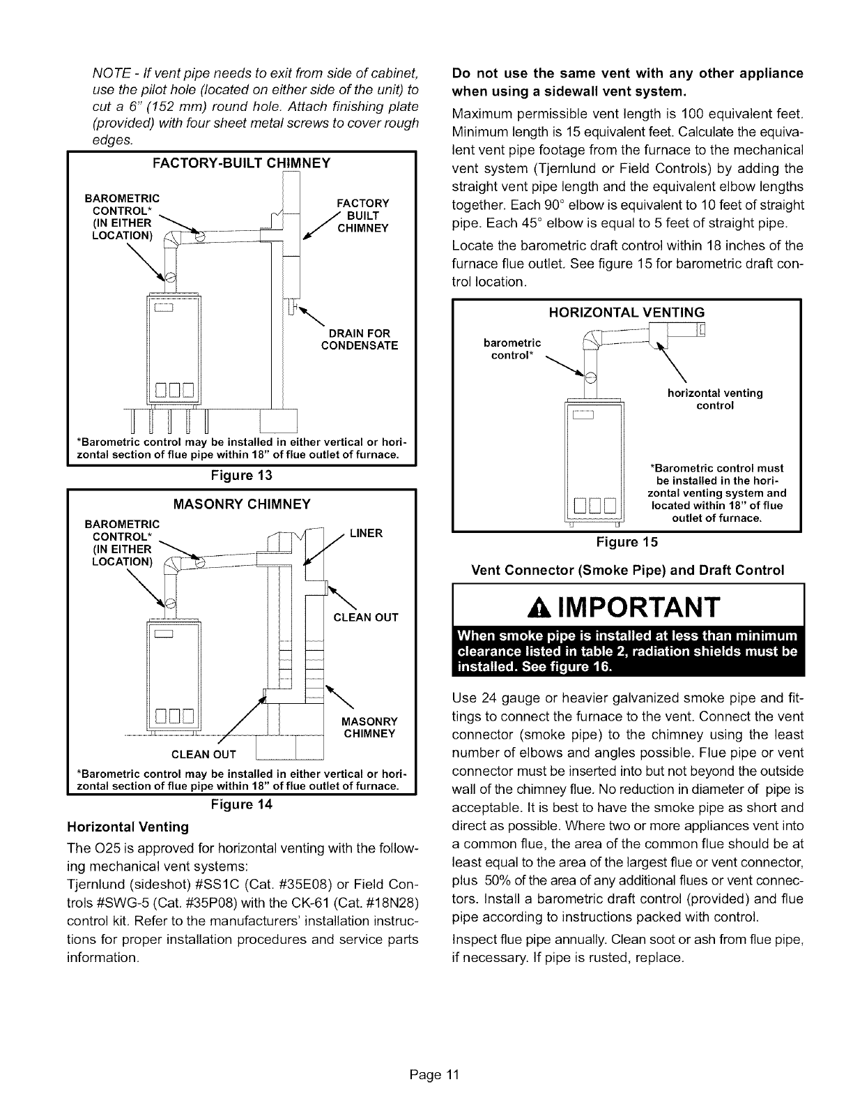
NOTE -If vent pipe needs to exit from side of cabinet,
use the pilot hole (located on either side of the unit) to
cut a 6" (152 mm) round hole. Attach finishing plate
(provided) with four sheet metal screws to cover rough
edges.
FACTORY-BUILT CHIMNEY
BAROMETRIC
CONTROL*
(IN EITHER
LOCATION)
\
E
DRAIN FOR
CONDENSATE
FHH L
*Barometric control may be installed in either vertical or hori-
zontal section of flue pipe within 18" of flue outlet of furnace.
Figure 13
MASONRY CHIMNEY
BAROMETRIC
CONTROL*
(IN EITHER
LOCATION)
LINER
CLEAN OUT
MASONRY
CHIMNEY
CLEAN OUT
*Barometric control may be installed in either vertical or hori-
zontal section of flue pipe within 18" of flue outlet of furnace.
Figure 14
Horizontal Venting
The 025 is approved for horizontal venting with the follow-
ing mechanical vent systems:
Tjernlund (sideshot) #SS1C (Cat, #35E08) or Field Con-
trois #SWG-5 (Cat, #35P08) with the CK-61 (Cat. #18N28)
control kit, Refer to the manufacturers' installation instruc-
tions for proper installation procedures and service parts
information,
Do not use the same vent with any other appliance
when using a sidewall vent system.
Maximum permissible vent length is 100 equivalent feet,
Minimum length is 15 equivalent feet. Calculate the equiva-
lent vent pipe footage from the furnace to the mechanical
vent system (Tjernlund or Field Controls) by adding the
straight vent pipe length and the equivalent elbow lengths
together, Each 90° elbow is equivalent to 10 feet of straight
pipe. Each 45° elbow is equal to 5 feet of straight pipe,
Locate the barometric draft control within 18 inches of the
furnace flue outlet, See figure 15 for barometric draft con-
trol location,
HORIZONTAL VENTING
barometric
control*
horizontal venting
-- control
F }
*Barometric control must
be installed in the hori-
zontal venting system and
located within 18" of flue
outlet of furnace.
Figure 15
Vent Connector (Smoke Pipe) and Draft Control
IMPORTANT
Use 24 gauge or heavier galvanized smoke pipe and fit-
tings to connect the furnace to the vent. Connect the vent
connector (smoke pipe) to the chimney using the least
number of elbows and angles possible, Flue pipe or vent
connector must be inserted into but not beyond the outside
wall of the chimney flue, No reduction in diameter of pipe is
acceptable, It is best to have the smoke pipe as short and
direct as possible, Where two or more appliances vent into
a common flue, the area of the common flue should be at
least equal to the area of the largest flue or vent connector,
plus 50% of the area of any additional flues or vent connec-
tors. Install a barometric draft control (provided) and flue
pipe according to instructions packed with control,
Inspect flue pipe annually. Clean soot or ash from flue pipe,
if necessary. If pipe is rusted, replace.
Page 11
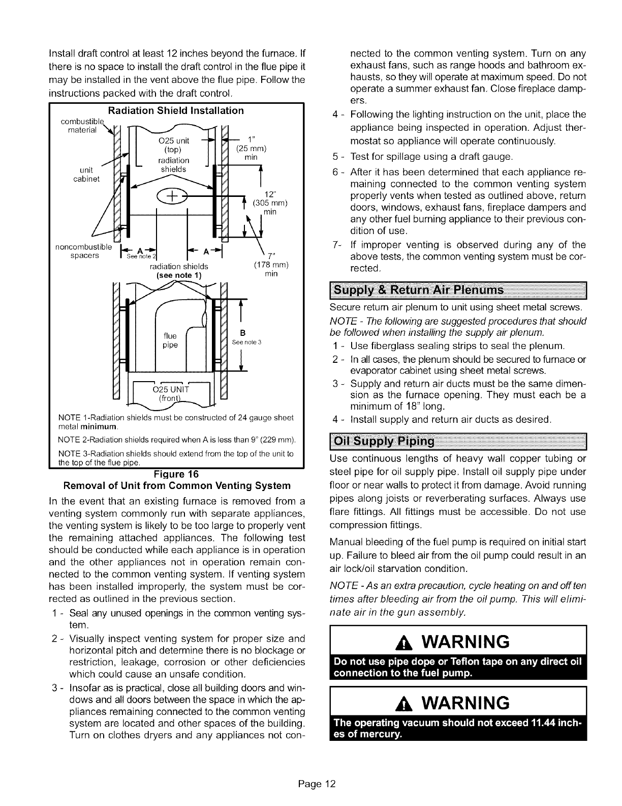
Installdraftcontrolatleast12inchesbeyondthefurnace.If
thereisnospacetoinstallthedraftcontrolinthefluepipeit
maybeinstalledintheventabovethefluepipe.Followthe
instructionspackedwiththedraftcontrol.
RadiationShieldInstallation
combustibl_
material
unit
cabinet
(25 mm)
min
12"
(305 mm)
min
noncombustible A._ _
spacers _See note: 11'- A-P'I 7"
radiation shields (178 mm)
(see note 1) min
B
See no{e 3
NOTE 1-Radiation shields must be constructed of 24 gauge sheet
metal minimum.
NOTE 2-Radiation shields required when A is less than 9" (229 mm).
NOTE 3-Radiation shields should extend from the top of the unit to
the top of the flue pipe.
Figure 16
Removal of Unit from Common Venting System
In the event that an existing furnace is removed from a
venting system commonly run with separate appliances,
the venting system is likely to be too large to properly vent
the remaining attached appliances. The following test
should be conducted while each appliance is in operation
and the other appliances not in operation remain con-
nected to the common venting system. If venting system
has been installed improperly, the system must be cor-
rected as outlined in the previous section.
1 - Seal any unused openings in the common venting sys-
tem.
2 - Visually inspect venting system for proper size and
horizontal pitch and determine there is no blockage or
restriction, leakage, corrosion or other deficiencies
which could cause an unsafe condition.
3 - Insofar as is practical, close all building doors and win-
dows and all doors between the space in which the ap-
pliances remaining connected to the common venting
system are located and other spaces of the building.
Turn on clothes dryers and any appliances not con-
nected to the common venting system. Turn on any
exhaust fans, such as range hoods and bathroom ex-
hausts, so they will operate at maximum speed. Do not
operate a summer exhaust fan. Close fireplace damp-
ers.
4 - Following the lighting instruction on the unit, place the
appliance being inspected in operation. Adjust ther-
mostat so appliance will operate continuously.
5 - Test for spillage using a draft gauge.
6 - After it has been determined that each appliance re-
maining connected to the common venting system
properly vents when tested as outlined above, return
doors, windows, exhaust fans, fireplace dampers and
any other fuel burning appliance to their previous con-
dition of use.
7- If improper venting is observed during any of the
above tests, the common venting system must be cor-
rected.
Secure retum air plenum to unit using sheet metal screws.
NOTE -The following are suggested procedures that should
be followed when installing the supply air plenum.
1 - Use fiberglass sealing strips to seal the plenum.
2 - In all cases, the plenum should be secured to furnace or
evaporator cabinet using sheet metal screws.
3 - Supply and return air ducts must be the same dimen-
sion as the furnace opening. They must each be a
minimum of 18" long.
4 - Install supply and return air ducts as desired.
Use continuous lengths of heavy wall copper tubing or
steel pipe for oil supply pipe. Install oil supply pipe under
floor or near walls to protect it from damage. Avoid running
pipes along joists or reverberating surfaces. Always use
flare fittings. All fittings must be accessible. Do not use
compression fittings.
Manual bleeding of the fuel pump is required on initial start
up. Failure to bleed air from the oil pump could result in an
air lock/oil starvation condition.
NOTE -As an extra precaution, cycle heating on and off ten
times after bleeding air from the oil pump. This will elimi-
nate air in the gun assembly.
Ak WARNING
Ak WARNING
Page 12
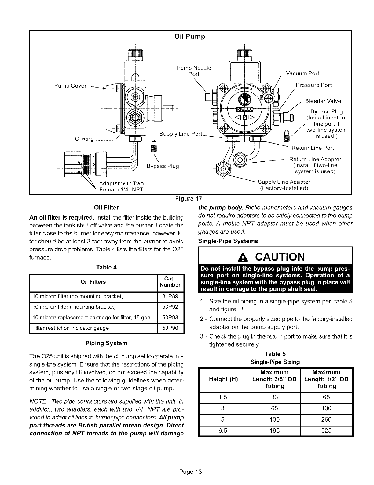
Oil Pump
Pump Cover
O-Ring
Adapter with Two
Female 1/4" NPT
Pump Nozzle
Port
\
Supply Line Port.
\
Bypass Plug
Oil Filter
An oil filter is required. Install the filter inside the building
between the tank shut-off valve and the burner. Locate the
filter close to the burner for easy maintenance; however, fil-
ter should be at least 3 feet away from the burner to avoid
pressure drop problems. Table 4 lists the filters for the 025
furnace.
Table 4
Cat.
Oil Filters Number
10 micron filter (no mounting bracket) 81P89
10 micron filter (mounting bracket) 53P92
10 micron replacement cartridge for filter, 45 gph 53P93
Filter restriction indicator gauge 53P90
Piping System
The 025 unit is shipped with the oil pump set to operate in a
single-line system. Ensure that the restrictions of the piping
system, plus any lift involved, do not exceed the capability
of the oil pump. Use the following guidelines when deter-
mining whether to use a single-or two-stage oil pump,
NOTE -Two pipe connectors are supplied with the unit. In
addition, two adapters, each with two 1/4" NPT are pro-
vided to adapt oil lines to burner pipe connectors. All pump
port threads are British parallel thread design. Direct
connection of NPT threads to the pump will damage
!
I Vacuum Port
dPressure Port
_,_/ BleederValve
"-'_ Bypass Plug
<_ [::> //]_-_.JJ ..... (Install in return
_ -' /line port if
__.7/ _ /two-line system
.__._ _ /is used.)
Return Line Port
Return Line Adapter
(Install if two-line
system is used)
Supply Line Adapter
(Factory-Installed)
Figure 17
the pump body. Riello manometers and vacuum gauges
do not require adapters to be safely connected to the pump
ports. A metric NPT adapter must be used when other
gauges are used.
Single-Pipe Systems
CAUTION
1 - Size the oil piping in a single-pipe system per table 5
and figure 18,
2 - Connect the properly sized pipe to the factory-installed
adapter on the pump supply port,
3 - Check the plug in the return port to make sure that it is
tightened securely.
Table 5
Single-Pipe Sizing
Maximum
Height (H) Length 3/8" OD
Tubing
1,5' 33
3' 65
5' 130
6,5' 195
Maximum
Length 1/2" OD
Tubing
65
130
26O
325
Page 13
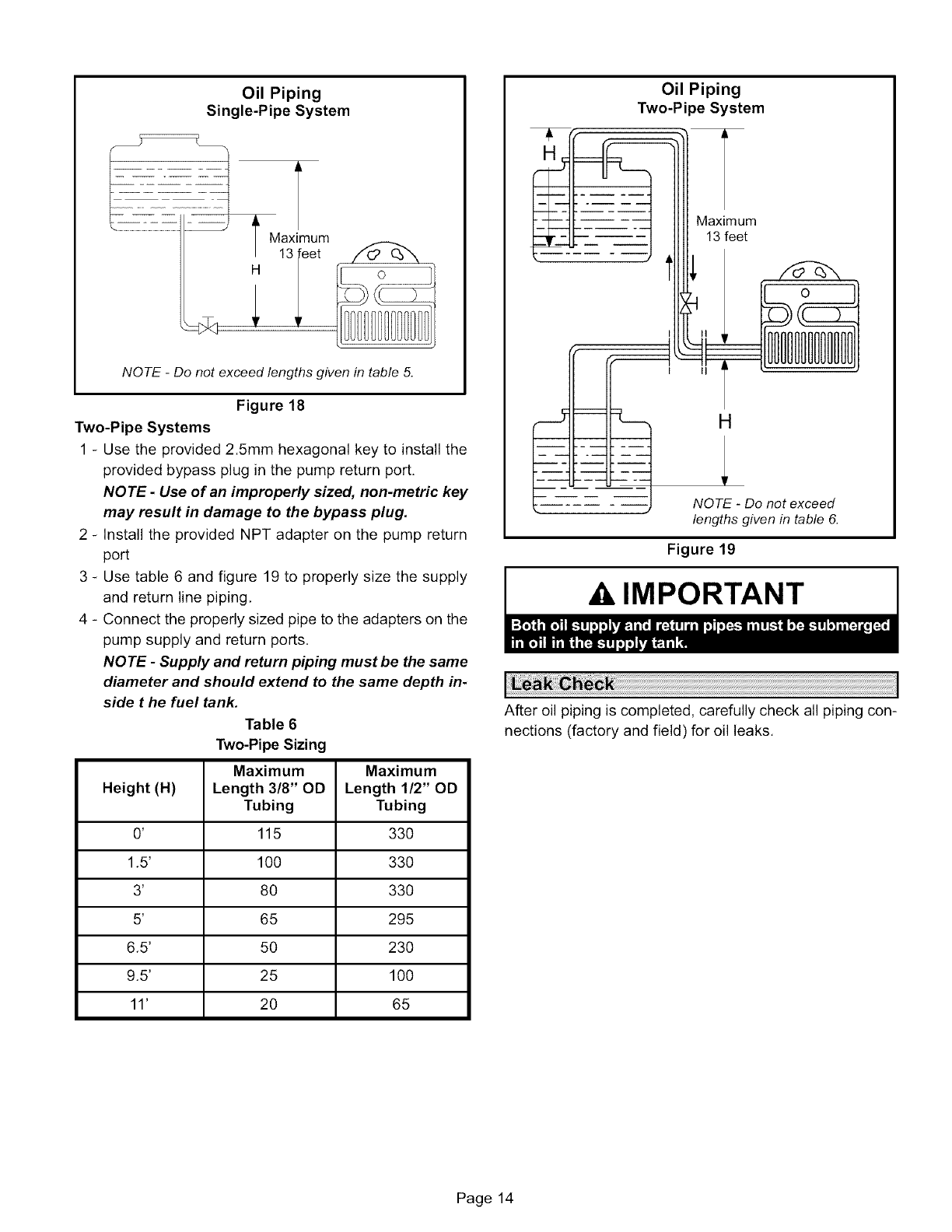
Oil Piping
Single-Pipe System
I Maximum
13
H
NOTE -Do not exceed lengths given in table 5.
Figure 18
Two-Pipe Systems
1 - Use the provided 2.5mm hexagonal key to install the
provided bypass plug in the pump return port.
NOTE- Use of an improperly sized, non-metric key
may result in damage to the bypass plug.
2 - Install the provided NPT adapter on the pump return
port
3 - Use table 6 and figure 19 to properly size the supply
and return line piping,
4 - Connect the properly sized pipe to the adapters on the
pump supply and return ports,
NOTE -Supply and return piping must be the same
diameter and should extend to the same depth in-
side t he fuel tank.
Table 6
Two-Pipe Sizing
Maximum
Height (H) Length 3/8" OD
Tubing
0' 115
1.5' 100
3' 80
5' 65
6.5' 5O
9.5' 25
11' 20
Maximum
Length 1/2" OD
Tubing
330
330
330
295
230
100
65
Oil Piping
Two-Pipe System
Maximum
13 feet
H
NOTE -Do not exceed
lengths given in table 6.
Figure 19
A, IMPORTANT
After oil piping is completed, carefully check all piping con-
nections (factory and field) for oil leaks.
Page 14
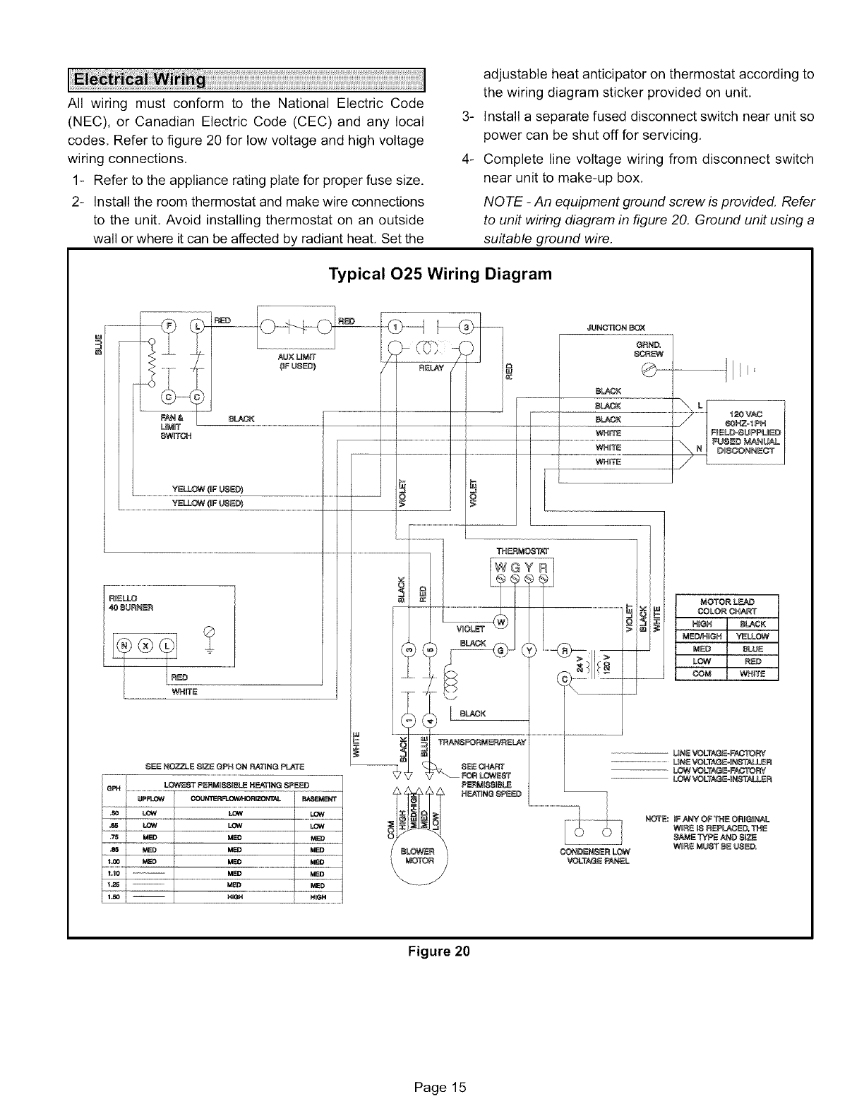
All wiringmustconformto the NationalElectricCode
(NEC),or CanadianElectricCode(CEC)andany local
codes,Refertofigure20forlowvoltageandhighvoltage
wiringconnections,
1- Refertotheapplianceratingplateforproperfusesize.
2- Installtheroomthermostatandmakewireconnections
totheunit.Avoidinstallingthermostatonan outside
wallorwhereitcanbeaffectedbyradiantheat,Setthe
_
4-
adjustable heat anticipator on thermostat according to
the wiring diagram sticker provided on unit,
Install a separate fused disconnect switch near unit so
power can be shut off for servicing,
Complete line voltage wiring from disconnect switch
near unit to make-up box,
NOTE -An equipment ground screw is provided. Refer
to un# wiring diagram in figure 20. Ground unit using a
suitable ground wire.
Typical 025 Wiring Diagram
FAN&
UM_T
8W_TON
....................................YELLOW {IF USE#}
YE&OW(IFUSE#} o
UNE VOLTAGE=F_Y
........................... L_NE VOLTAGE4 NSTA_LER
LOW VOLTAG_FACTORY
LOW VOLTAGE4N_ALL_R
Figure 20
Page 15
Before starting unit, make sure the oil tank is ade-
quately filled with clean No. 2 furnace oil.
NOTE -Water, rust or other contaminants in oil supply sys-
tem will cause malfunction and failure of the internal parts
of the fuel pump.
Single-Pipe Systems
1 - Loosen the pump bleeder valve until oil flows out.
NOTE -If no oil comes out of the loosened bleeder
port, re-tighten the bleeder valve securely and add oil
through the vacuum port. Use 4mm hex key to remove
vacuum port plug.
2 - Disconnect nozzle oil supply line at the pump nozzle
port,
3 - Attach one end of a flexible plastic tube to the pump
nozzle port, Direct the other end of the flexible tube
into a bucket and allow the oil to flow into the bucket.
4 - Loosen the screw(s) which secure the air tube cover,
5 - Hold the air tube cover in its proper position and start
the burner,
6 - Allow the solenoid valve to engage (approximately 10
seconds after burner fires), Remove the air tube cover
and shine a light source on the photo-cell, The cell
must sense light.
7 - Run the burner until the fuel pump has been purged of
air, then tighten the bleeder valve and immediately
shut down the burner.
8 - Reinstall the air tube cover and nozzle line.
9 - Start the burner normally.
WARNING
Two-Pipe Systems
1 - Turn off main power source to the burner and remove
the air tube cover.
2 - Shine a light source on the photo-cell. As long as the
light source remains on the photo-cell, the solenoid
valve will not open and the burner will continue to oper-
ate in pre-purge mode only,
3 - Return power to the burner and fire the burner,
NOTE -Burner will operate in pre-purge only as long
as the light source shines on the photo-cell,
4 - Run the burner until the fuel pump has been purged of
air,
5 - Replace air tube cover.
6 - Restore power to the burner and start the burner nor-
mally.
A CAUTION
A CAUTION
A WARNING
1 - Set thermostat for heating demand and turn on electri-
cal supply to unit.
2 - If burner fails to start, push reset button on primary
safety control and the burner motor reset button on the
front of the burner,
A CAUTION
3 - If the burner fails to light again, refer to the trouble-
shooting section in this manual.
Fuel Pump Pressure
Use 11mm wrench to remove bleeder port cover, Attach
Riello gauge (or use adapter to attach NPT gauge) to
bleeder port, Turn unit on and measure fuel pump pres-
sure. Check pressure and compare to table 1. Adjust if nec-
essary. Vacuum Pressure
Use 4mm hex key to remove vacuum port cover, Attach
Riello gauge (or use adapter to attach NPT gauge) to
bleeder port, Start burner and measure operating vacuum,
Operating vacuum should not exceed 11.44 inches w.c.
Correct, if necessary,
Temperature Rise
To measure temperature rise, place plenum thermometers
in warm air and return air plenums, Locate thermometer in
warm air plenum where thermometer will not "see" the heat
exchanger to prevent it from picking up radiant heat. Set
thermostat to its highest setting to start unit, After plenum
thermometers have reached their highest and steadiest
readings, subtract the readings, The difference in tempera-
tures in the supply and return air plenums should approxi-
mate the temperature rise range listed on the unit rating
plate. If not, adjust the blower motor pulley to adjust the
blower speed.
Fan and Limit Control
The fan and limit control is factory installed and wired.
Page 16
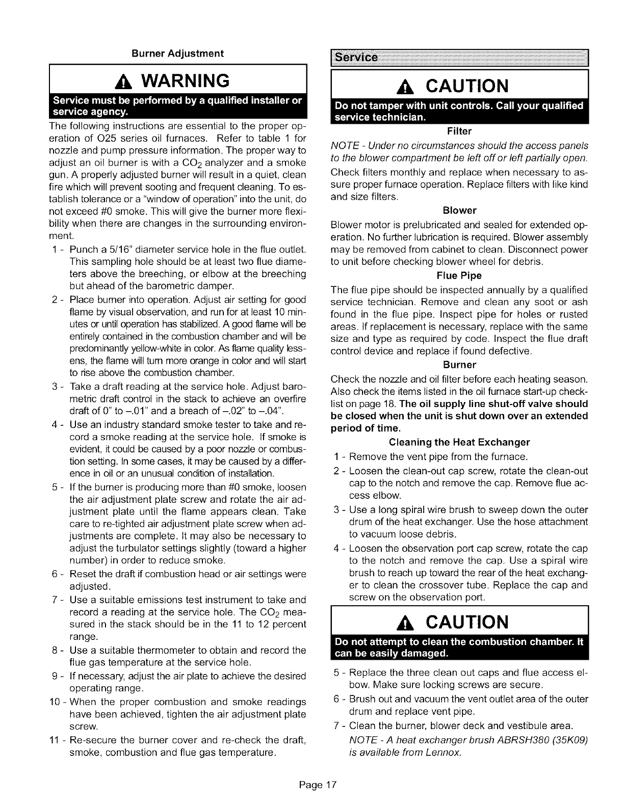
Burner Adjustment
WARNING A CAUTION
The following instructions are essential to the proper op-
eration of 025 series oil furnaces, Refer to table 1 for
nozzle and pump pressure information. The proper way to
adjust an oil burner is with a CO2 analyzer and a smoke
gun. A properly adjusted burner will result in a quiet, clean
fire which will prevent sooting and frequent cleaning. To es-
tablish tolerance or a "window of operation" into the unit, do
not exceed #0 smoke, This will give the burner more flexi-
bility when there are changes in the surrounding environ-
ment,
1 - Punch a 5/16" diameter service hole in the flue outlet.
This sampling hole should be at least two flue diame-
ters above the breeching, or elbow at the breeching
but ahead of the barometric damper,
2 - Place burner into operation. Adjust air setting for good
flame by visual observation, and run for at least 10 min-
utes or until operation has stabilized. A good flame will be
entirely contained in the combustion chamber and will be
predominantly yellow-white in color.As flame quality less-
ens, the flame will turn more orange in color and will start
to rise above the combustion chamber.
3 - Take a draft reading at the service hole. Adjust bare-
metric draft control in the stack to achieve an overfire
draft of 0" to -,01" and a breach of -,02" to -.04",
4 - Use an industry standard smoke tester to take and re-
cord a smoke reading at the service hole. If smoke is
evident, it could be caused by a poor nozzle or combus-
tion setting. Insome cases, it may be caused by a differ-
ence in oil or an unusual condition of installation,
5- If the burner is producing more than #0 smoke, loosen
the air adjustment plate screw and rotate the air ad-
justment plate until the flame appears clean. Take
care to re-tighted air adjustment plate screw when ad-
justments are complete, It may also be necessary to
adjust the turbulator settings slightly (toward a higher
number) in order to reduce smoke,
6- Reset the draft if combustion head or air settings were
adjusted.
7 - Use a suitable emissions test instrument to take and
record a reading at the service hole, The CO2 mea-
sured in the stack should be in the 11 to 12 percent
range,
8 - Use a suitable thermometer to obtain and record the
flue gas temperature at the service hole,
g - If necessary, adjust the air plate to achieve the desired
operating range.
10-When the proper combustion and smoke readings
have been achieved, tighten the air adjustment plate
screw.
11 - Re-secure the burner cover and re-check the draft,
smoke, combustion and flue gas temperature,
Filter
NOTE -Under no circumstances should the access panels
to the blower compartment be left off or left partially open.
Check filters monthly and replace when necessary to as-
sure proper furnace operation, Replace filters with like kind
and size filters,
Blower
Blower motor is prelubricated and sealed for extended op-
eration. No further lubrication is required, Blower assembly
may be removed from cabinet to clean, Disconnect power
to unit before checking blower wheel for debris,
Flue Pipe
The flue pipe should be inspected annually by a qualified
service technician, Remove and clean any soot or ash
found in the flue pipe. Inspect pipe for holes or rusted
areas. If replacement is necessary, replace with the same
size and type as required by code, Inspect the flue draft
control device and replace if found defective,
Burner
Check the nozzle and oil filter before each heating season.
Also check the items listed in the oil furnace start-up check-
list on page 18. The oil supply line shut-off valve should
be closed when the unit is shut down over an extended
period of time.
Cleaning the Heat Exchanger
1 - Remove the vent pipe from the furnace,
2 - Loosen the clean-out cap screw, rotate the clean-out
cap to the notch and remove the cap, Remove flue ac-
cess elbow.
3 - Use a long spiral wire brush to sweep down the outer
drum of the heat exchanger. Use the hose attachment
to vacuum loose debris.
4 - Loosen the observation port cap screw, rotate the cap
to the notch and remove the cap, Use a spiral wire
brush to reach up toward the rear of the heat exchang-
er to clean the crossover tube, Replace the cap and
screw on the observation port,
Ak CAUTION
5 - Replace the three clean out caps and flue access el-
bow. Make sure locking screws are secure,
6 - Brush out and vacuum the vent outlet area of the outer
drum and replace vent pipe,
7 - Clean the burner, blower deck and vestibule area,
NOTE -A heat exchanger brush ABRSH380 (35K09)
is available from Lennox.
Page 17
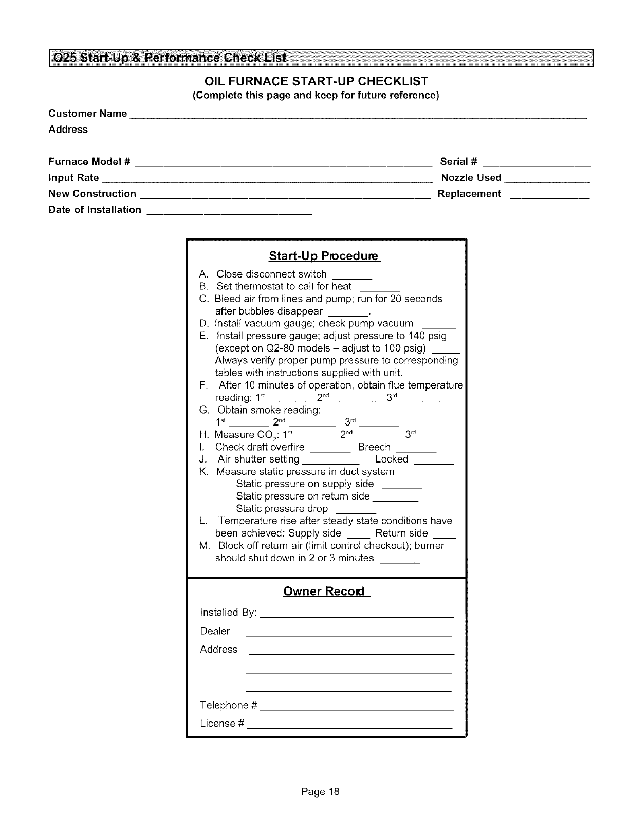
Customer Name
Address
OIL FURNACE START-UP CHECKLIST
(Complete this page and keep for future reference)
Furnace Model #
Input Rate
New Construction
Date of Installation
Serial #
Nozzle Used
Replacement
Start-Up Procedure
A. Close disconnect switch
B. Set thermostat to call for heat
C, Bleed air from lines and pump; run for 20 seconds
after bubbles disappear
D. Install vacuum gauge; check pump vacuum
E, Install pressure gauge; adjust pressure to 140 psig
(except on Q2-80 models - adjust to 100 psig) __
Always verify proper pump pressure to corresponding
tables with instructions supplied with unit.
F, After 10 minutes of operation, obtain flue temperature
reading: 1_ 2nd
G, Obtain smoke reading:
1st 2nd
H, Measure CO2:1 st
I, Check draft overfire
J. Air shutter setting
K,
L,
M
3 _
3 rd
2 nd 3 rd
Breech
Locked
Measure static pressure in duct system
Static pressure on supply side
Static pressure on return side
Static pressure drop
Temperature rise after steady state conditions have
been achieved: Supply side __ Return side __
Block off return air (limit control checkout); burner
should shut down in 2 or 3 minutes
Installed By:
Dealer
Address
Owner Recoil
Telephone #
License #
Page 18
