LENNOX Air Conditioner/heat Pump(outside Unit) Manual L0806422
User Manual: LENNOX LENNOX Air conditioner/heat pump(outside unit) Manual LENNOX Air conditioner/heat pump(outside unit) Owner's Manual, LENNOX Air conditioner/heat pump(outside unit) installation guides
Open the PDF directly: View PDF ![]() .
.
Page Count: 20
,?_2008 Lennox industries Inc,
Dallas, Texas, USA
INSTALLATION
INSTRUCTIONS
Merit®Series13HPX Units
HEAT PUMP UNITS _Technical
505,325M LLJJ Publications
03/08 Litho U.S.A.
Supersedes 07/07
WARNING
A CAUTION
AIMPORTANT
IMPORTANT
13HPX Outdoor Unit ........................... 1
Shipping and Packing List ...................... 1
Unit Dimensions ............................... 2
General Information ........................... 2
Setting the Unit ............................... 3
Electrical ..................................... 4
Refrigerant Piping ............................. 6
Flushing Existing Line Set and Indoor Coil ........ 8
Refrigerant Metering Device .................... 10
Manifold Gauge Set ........................... 10
Service Valves ................................ 10
Leak Testing .................................. 11
Evacuation ................................... 11
Start-Up ...................................... 12
Refrigerant Charge ............................ 12
Checking Airflow .............................. 12
Setup for Checking and Adding Charge .......... 13
System Operation ............................. 17
Defrost System ............................... 17
Maintenance .................................. 18
Optional Accessories .......................... 19
Homeowner Information ........................ 19
Thermostat Operation .......................... 20
13HPX Check List ............................. 20
RETAIN THESE INSTRUCTIONS
FOR FUTURE REFERENCE
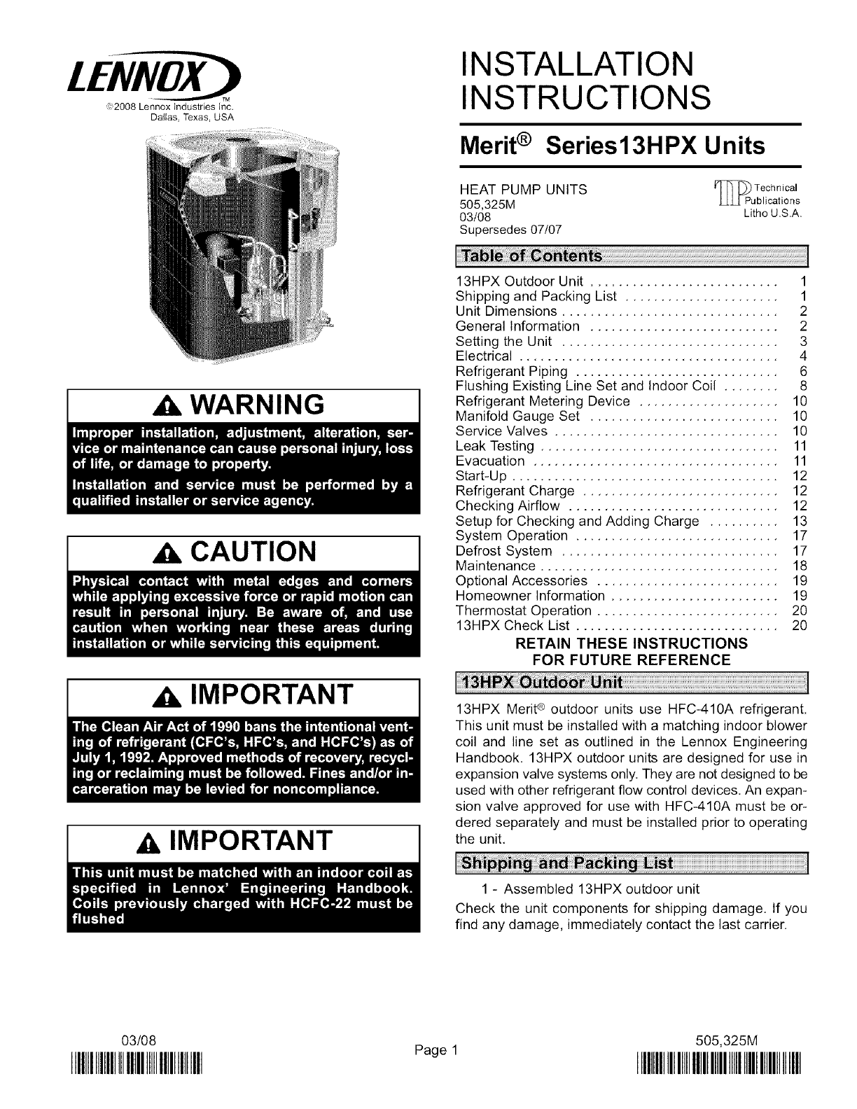
13HPX Merit ® outdoor units use HFC-410A refrigerant.
This unit must be installed with a matching indoor blower
coil and line set as outlined in the Lennox Engineering
Handbook. 13HPX outdoor units are designed for use in
expansion valve systems only. They are not designed to be
used with other refrigerant flow control devices. An expan-
sion valve approved for use with HFC-410A must be or-
dered separately and must be installed prior to operating
the unit.
1 - Assembled 13HPX outdoor unit
Check the unit components for shipping damage. If you
find any damage, immediately contact the last carrier.
03/08
IIIHIIIIIIIIIIIIIIIIIIIIIIIIIIIIIIIII Page 1 505,325M
IIIIIIIIIIIIIIIIIIIIIIIIIIIIIIIIIIIIIIIIIIIIIIIIII
Inlet Air
,_lnletAir
©
InletAir
Vapor Line
Connection
Ai'_ru Liquid Line
Inlet Connection
Optional Unit Stand-
off Kit (4) (Field-
installed',
Coil Drain Outlets
(Around Perimeter
Of Base)
4-3/8
(111)
6-3/8
(182)
4-3/8
(111)
4-3/8
(111)
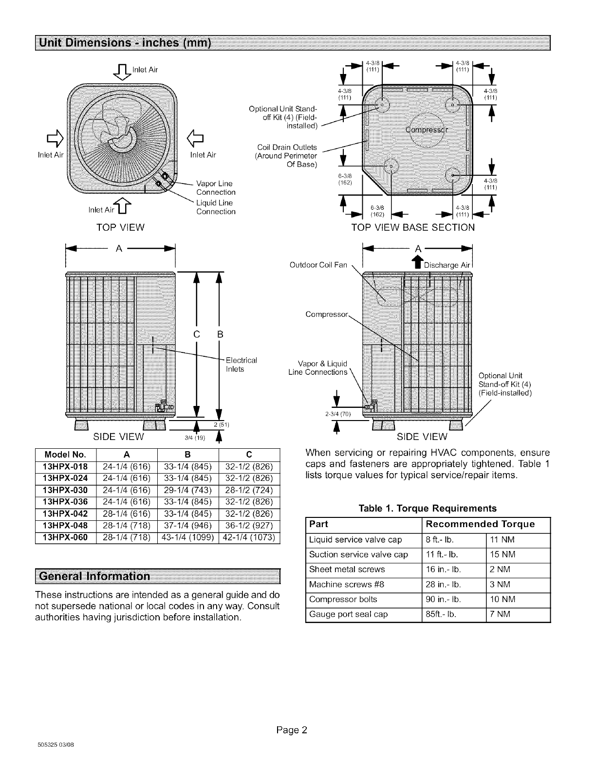
TOP VIEW TOP VIEW BASE SECTION
SIDE VIEW
Model No. A C
13HPX-018 24-1/4 (616) 32-1/2 (826)
13HPX-024 24-1/4 (616) 32-1/2 (826)
13HPX-030 24-1/4 (616) 28-1/2 (724)
13HPX-036 24-1/4 (616) 32-1/2 (826)
13HPX-042 28-1/4 (616) 32-1/2 (826)
13HPX-048 28-1/4 (718) 36-1/2 (927)
13HPX-060 28-1/4 (718) 42-1/4 (1073)
3/4 (19)
B
33-1/4 (845)
33-1/4 (845)
29-1/4 (743)
33-1/4 (845)
33-1/4 (845)
37-1/4 (946)
43-1/4 (1099)
These instructions are intended as a general guide and do
not supersede national or local codes in any way. Consult
authorities having jurisdiction before installation.
OutdoorCoil Fan \ tDischarge
Compressor_
Vapor & Liquid
Line Connections
L
2-3/4 (70)
Optional Unit
Stand-off Kit (4)
(Field-installed)
SIDE VIEW
When servicing or repairing HVAC components, ensure
caps and fasteners are appropriately tightened. Table 1
lists torque values for typical service/repair items.
Table 1. Torque Requirements
Part Recommended Torque
Liquid service valve cap 8 ft.- lb. 11 NM
Suction service valve cap 11 ft.- lb. 15 NM
Sheet metal screws 16 in.- lb. 2 NM
Machine screws #8 28 in.- lb. 3 NM
Compressor bolts 90 in.- lb. 10 NM
Gauge port seal cap 85ft.- lb. 7 NM
505325 03/08
Page 2
WARNING
CAUTION
Outdoor units operate under a wide range of weather con-
ditions; therefore, several factors must be considered
when positioning the outdoor unit. Unit must be positioned
to give adequate clearances for sufficient airflow and servi-
cing. A minimum clearance of 24 inches (610 mm) be-
tween multiple units must be maintained. Refer to figure 1
for installation clearances.
1. Place a sound-absorbing material, such as Isomode,
under the unit if it will be installed in a location or posi-
tion that will transmit sound or vibration to the living
area or adjacent buildings.
2. Mount unit high enough above ground or roof to allow
adequate drainage of defrost water and prevent ice
build-up.
3. In heavy snow areas, do not locate unit where drifting
will occur. The unit base should be elevated above the
depth of average snows.
NOTE- Elevation of the unit may be accomplished by
constructing a frame using suitable materials. Ira sup-
port frame is constructed, it must not block drain holes
in unit base.
4. When installed in areas where low ambient tempera-
tures exist, locate unit so winter prevailing winds do
not blow directly into outdoor coil.
5. Locate unit away from overhanging roof lines which
would allow water or ice to drop on, or in front of, coil
or into unit.
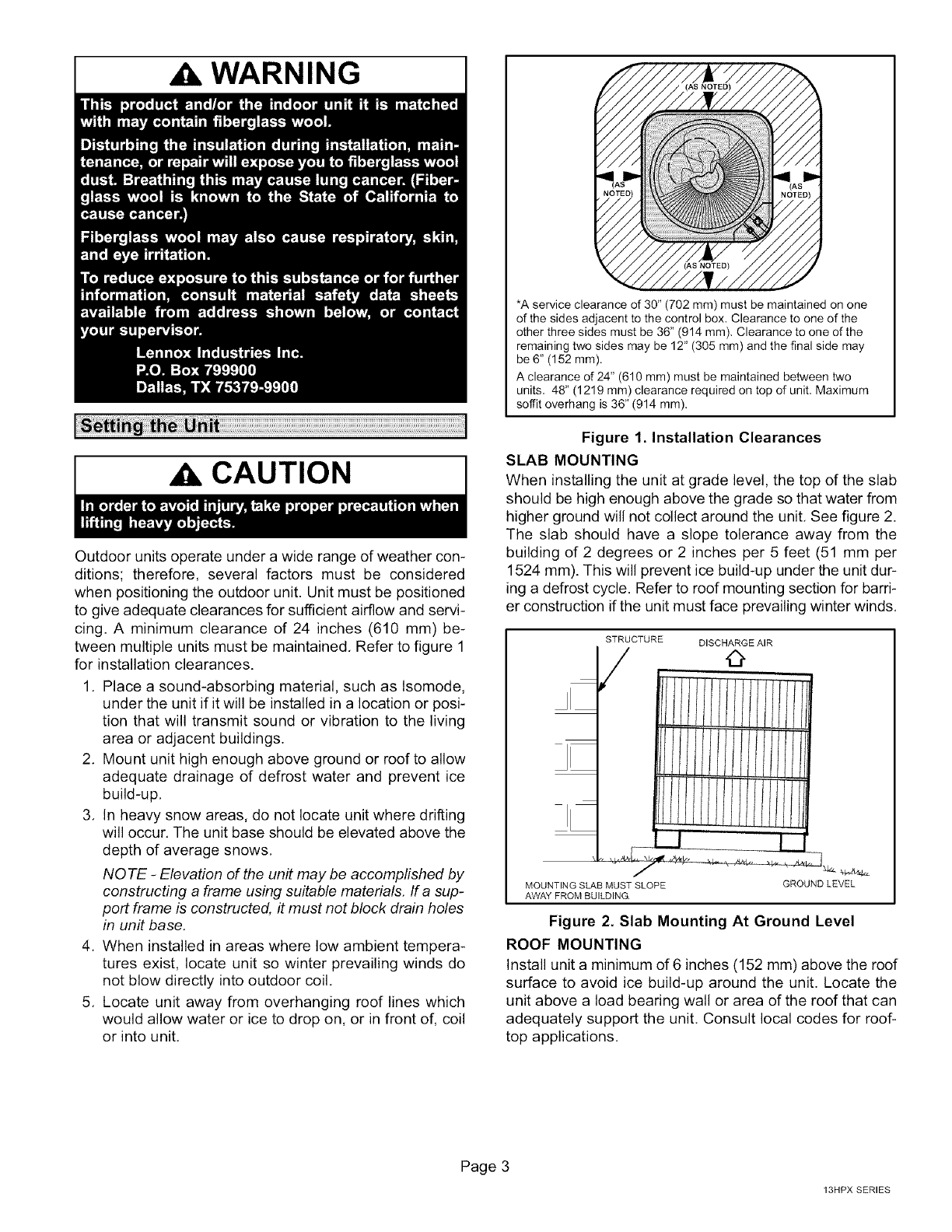
(AS NOTED)
*A service clearance of 30" (702 mm) must be maintained on one
of the sides adjacent to the control box. Clearance to one of the
other three sides must be 36" (914 mm), Clearance to one of the
remaining two sides may be 12" (305 mm) and the final side may
be 6" (152 mm).
A clearance of 24" (610 mm) must be maintained between two
units, 48" (1219 mm) clearance required on top of unit, Maximum
soffit overhang is 36" (914 mm).
Figure 1 Installation Clearances
SLAB MOUNTING
When installing the unit at grade level, the top of the slab
should be high enough above the grade so that water from
higher ground will not collect around the unit, See figure 2.
The slab should have a slope tolerance away from the
building of 2 degrees or 2 inches per 5 feet (51 mm per
1524 mm). This will prevent ice build-up under the unit dur-
ing a defrost cycle. Refer to roof mounting section for barri-
er construction if the unit must face prevailing winter winds,
STRUCTURE DISCHARGE AIR
,I/I/I/I/I/
l/I/////
MOUNTING SLAB MUST SLOPE
AWAY FROM BUILDING.
GROUNDLEVEL
Figure 2. Slab Mounting At Ground Level
ROOF MOUNTING
Install unit a minimum of 6 inches (152 mm) above the roof
surface to avoid ice build-up around the unit. Locate the
unit above a load bearing wall or area of the roof that can
adequately support the unit, Consult local codes for roof-
top applications,
Page 3
13HPX SERIES
PREVAILINGWINTERWINDS
©
I WINDBARRIER I
INLET AIR
INLET AIR INLET AIR
0 0
0
INLET AIR
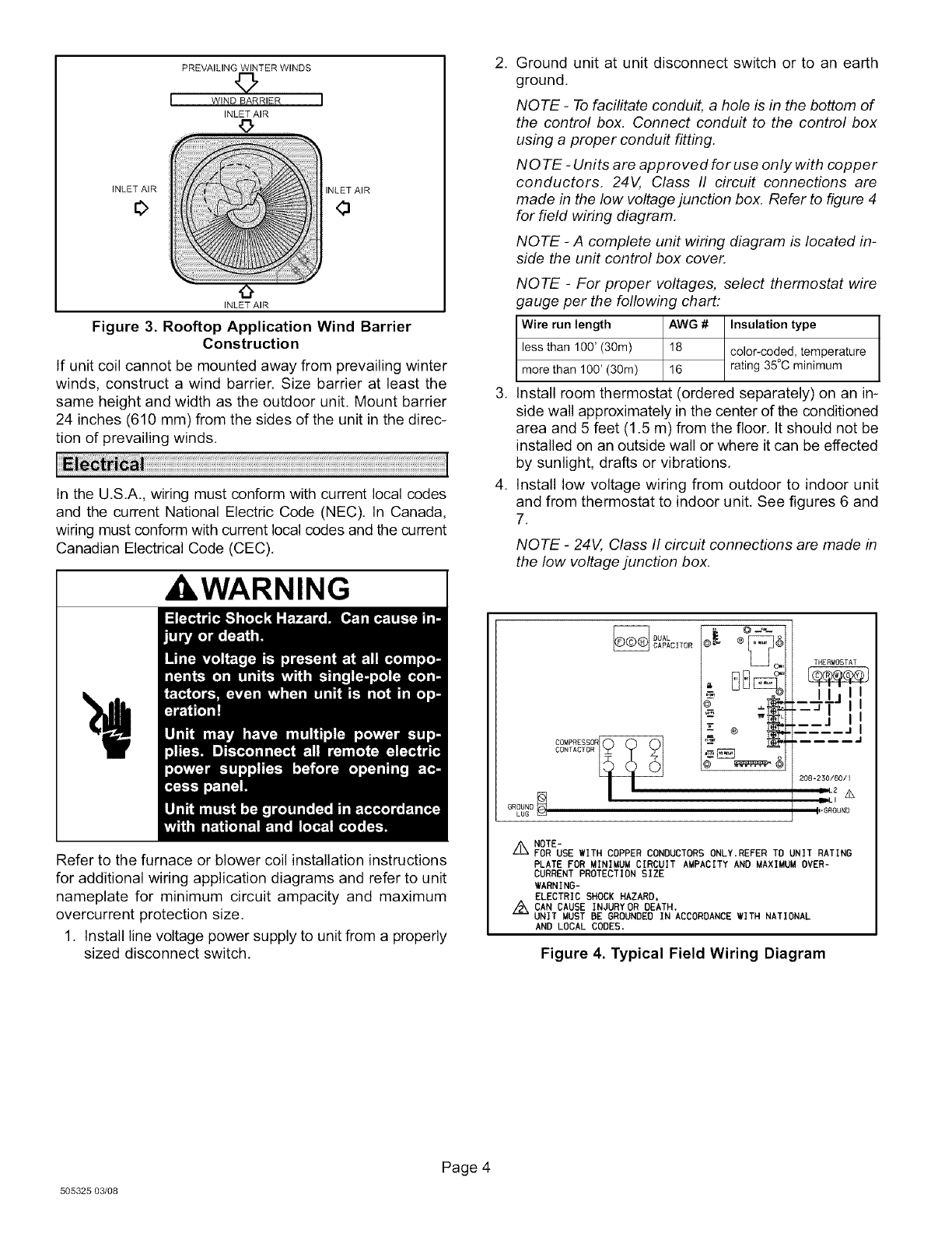
Figure 3. Rooftop Application Wind Barrier
Construction
If unit coil cannot be mounted away from prevailing winter
winds, construct a wind barrier. Size barrier at least the
same height and width as the outdoor unit. Mount barrier
24 inches (610 mm) from the sides of the unit in the direc-
tion of prevailing winds.
In the U.S.A., wiring must conform with current local codes
and the current National Electric Code (NEC). In Canada,
wiring must conform with current local codes and the current
Canadian Electrical Code (CEC).
WARNING I
Refer to the furnace or blower coil installation instructions
for additional wiring application diagrams and refer to unit
nameplate for minimum circuit ampacity and maximum
overcurrent protection size.
1. Install line voltage power supply to unit from a properly
sized disconnect switch.
.
.
.
Ground unit at unit disconnect switch or to an earth
ground.
NOTE -To facilitate conduit, a hole is in the bottom of
the control box. Connect conduit to the control box
using a proper conduit fitting.
NO TE -Units are approved for use only with copper
conductors. 24V, Class II circuit connections are
made in the low voltage junction box. Refer to figure 4
for field wiring diagram.
NOTE -A complete unit wiring diagram is located in-
side the unit control box cover.
NOTE -For proper voltages, select thermostat wire
gauge per the following chart:
Wire run length AWG # Insulation type
less than 100' (30m) 18 color-coded, temperature
more than 100' (30m) 16 rating 35°C minimum
Install room thermostat (ordered separately) on an in-
side wall approximately in the center of the conditioned
area and 5 feet (1.5 m) from the floor. It should not be
installed on an outside wall or where it can be effected
by sunlight, drafts or vibrations.
Install low voltage wiring from outdoor to indoor unit
and from thermostat to indoor unit. See figures 6 and
7.
NOTE - 24V, Class II circuit connections are made in
the low voltage junction box.
OUAL
CAPACITOR @_ @ ._.-
_C_
--- @
THERIIOST AT
,_ I I_j, I
_-_J_j II
..... .I
208-230/60/I
mll 2 _
1,6ROUND
Z_ NOTE-
FOR USE WITH COPPER CONDUCTORS ONLY.REFER TO UNIT RATING
PLATE FOR MINIMUM CIRCUIT AUPACITY AND MAXIMUM OVER-
CURRENT PROTECTION SIZE
WARNING-
ELECTRIC SHOCK HAZARD,
Z_ CAN CAUSE INJURYOR DEATH.
UNIT MUST BE GROUNDED IN ACCORDANCE WITH NATIONAL
AND LOCAL CODES.
Figure 4. Typical Field Wiring Diagram
505325 03/08
Page 4
OUTDOOR
FAN
PURPLE
BLACK
ORANGE
RED
LLOW
COMPRESSOR
CRANKCASE HEATER
BLACK
GROUND
LUG
)_DUAL
CAPACITOR
BLACK
BLACK
DEFROST CONTROL
FAN
T
pOUT
LO-PS R 0
-_ O 0
YI
COMMON
Y I BUT
HI=PS
THERMOSTAT
o.r_.,o®e]
I I I t _
Iljll
----Jl II
J I I
J l
J
208-230/60/I
IIL2 z_x
DLE
I,'BROUNO
CMC
FAN
o OUT
LO--PB
OF L
RO
COMMON yO
_OUT I
HI -PS
THERMOSTATOEPROSTb _REVERSINGvALVE
LB20:B3OXBOZ';
"]_ _IORANGF ¢_
T _ BLACK IS
I_._ b Ir- r_v _ I
EQUIPMENTHR' ]__A_ _L-_c_ SLACK KI_
r_ NOTE-
FOR USE WITH COPPER CONDUCTORS
DESCRIPTION ONLY.REFER TO UNIT RATING
<EY COMPONENT PLATE FOR MINIMUM CIRCUIT
hi COMPRESSOR AMPACITY AND MAXIMUM OVER-
84- _OTOR-OUTDOOR FAN CURRENT PROTECTION SIZE.
CJ2 CAPACITOR- DUAL
CMCI CONTROL-DEFROST A
4RI hEATER-COMPRESSOR $41 TO BE MOUNTED IN
_11-1 :ONTACTOR-COMPREBBOR CONTROL BOX AND WIRED
L ¢ALVE=REVERSING IN PARALLEL WITH LOW
]4 _WITCH=HIGH PRESSURE PRESSURE SWITCH
_6 5W] TCH=DEFROST
540 THERMOSTAT-CRANKCASE
341 FHERMOSTAT=LOW AMBIEN_
_87 _WITCH=LOW PRESSURE
LOW 587
__ I I I LOW
II_)_ZENTpRESSU2#
II
'11
I I
CONNECTION MUST BE JUMPERED WHEN
OPTIONAL SWITCH IS NOT USED
WARNING-
ELECTRIC SHOCK HAZARD,CAN CAUSE INJURY OR
DEATH. UNIT MUST BE GROUNDED IN ACCORDANCE
WITH NATIONAL AND LOCAL CODES,
-,,_-------DENOTES OPTIONAL COMPONENTS
LINE VOLTAGE FIELD INSTALLED
-- -- -- CLASS I I VOLTAGE FIELD INSTALLED
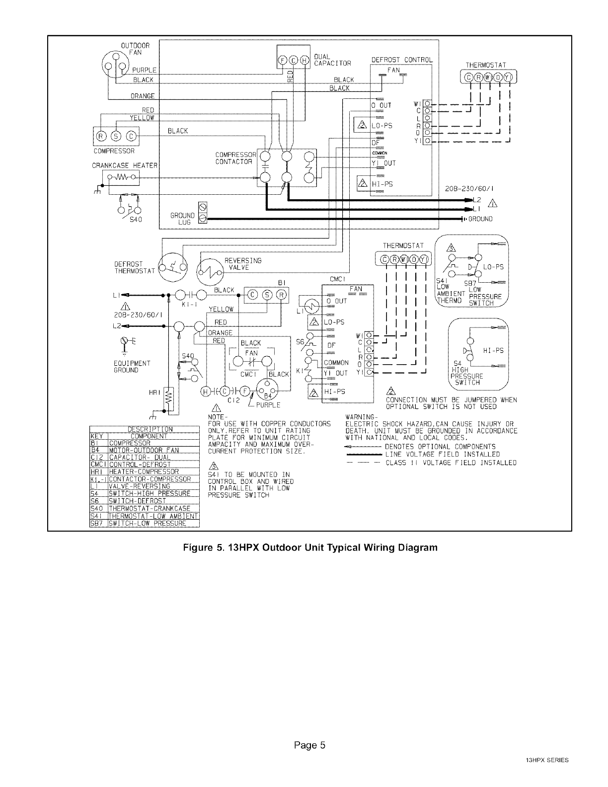
Figure 5. 13HPX Outdoor Unit Typical Wiring Diagram
Page 5
13HPX SERIES
Thermostat
power
common
(_) 1st. stage aux. heat
Indoor
Unit
-k_
@
indoor blower .
reversing valve
compressor
(SOME CONNECTIONS MAY NOT APPLY. REFER
TO SPECIFIC THERMOSTAT AND INDOOR UNIT.)
Outdoor
Unit
power
common
1st. stage aux. heat _)
G
@
Figure 6.13HPX and Blower Unit Thermostat Desig-
nations
Indoor
Thermostat Unit
®
power
common ¢
L
emergency heat It
]
I
I
1st. stage aux. heat _-
L
indoor blower
reversing valve
.power
_ common
emer.
J outdoor t'stat
-lZ_st. stage aux. heat
@J
®l
compressor
(SOME CONNECTIONS MAY NOT APPLY. REFER TO
SPECIFIC THERMOSTAT AND INDOOR UNIT.)
Outdoor
Unit
Figure 7. Outdoor Unit and Blower Unit Thermostat
Designations (with auxiliary heat)
If the 13HPX unit is being installed with a new indoor coil
and line set, the plumbing connections should be made as
outlined in this section. If an existing line set and/or indoor
coil is going to be used to complete the 13HPX system, re-
fer to the following section that includes flushing proce-
dures,
Field refrigerant piping consists of liquid and vapor lines
from the outdoor unit (sweat connections) to the indoor coil
(flare or sweat connections).
Use Lennox L15 (sweat, non-flare) series line sets as
shown in table 2 or use field-fabricated refrigerant lines,
Refer to Refrigerant Piping Guide (Corp. 9351-L9) for
proper size, type, and application of field-fabricated lines.
Valve sizes are also listed in table 2,
PLUMBING CONNECTIONS--13HPX MATCHED
WITH NEW INDOOR COIL AND LINE SET
If you are replacing an existing coil that is equipped with a
liquid line functioning as a metering orifice, replace the liq-
uid line prior to installing the 13HPX unit, See table 2.
Model
-018
-024
-030
-O36
-042
-048
-060
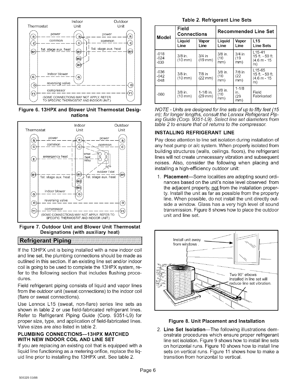
Table 2. Refrigerant Line Sets
Field
Connections
Liquid Vapor
Line Line
3/8 in. 3/4 in
(10 mm) (19 mm)
3/8 in. 7/8 in
(10 mm) (22 mm)
3/8 in, 1-1/8 in.
(10 mm) (29 mm)
Recommended Line Set
Liquid Vapor L15
Line Line Line Sets
3/8 in. 3/4 in L15-41
(10 (19 15ft,- 50ft.
mm) mm) (4.6 m - 15
m)
3/8 in. 7/8 in L15-65
(10 (22 15ft.- 50 ft.
mm) mm) (4.6 m - 15
m)
3/8 in. 1-1/8
in, Field
(10
mm) (29) Fabricated
NOTE -Units are designed for line sets of up to fifty feet (15
m); for longer lengths, consult the Lennox Refrigerant Pip-
ing Guide (Corp. 9351-L9). Select line set diameters from
table 2 to ensure that oil returns to the compressor.
INSTALLING REFRIGERANT LINE
Pay close attention to line set isolation during installation of
any heat pump or a/c system. When properly isolated from
building structures (walls, ceilings, floors), the refrigerant
lines will not create unnecessary vibration and subsequent
noises. Also, consider the following when placing and
installing a high-efficiency outdoor unit:
1. Placement--Some localities are adopting sound ordi-
nances based on the unit's noise level observed from
the adjacent property, not from the installation proper-
ty. Install the unit as far as possible from the property
line. When possible, do not install the unit directly out-
side a window. Glass has a very high level of sound
transmission. Figure 8 shows how to place the outdoor
unit and line set.
Install unit away
from windows.
Two 90 ° elbows
installed in line set will
line set vibration.
Figure 8. Unit Placement and Installation
2. Line Set Isolation--The following illustrations dem-
onstrate procedures which ensure proper refrigerant
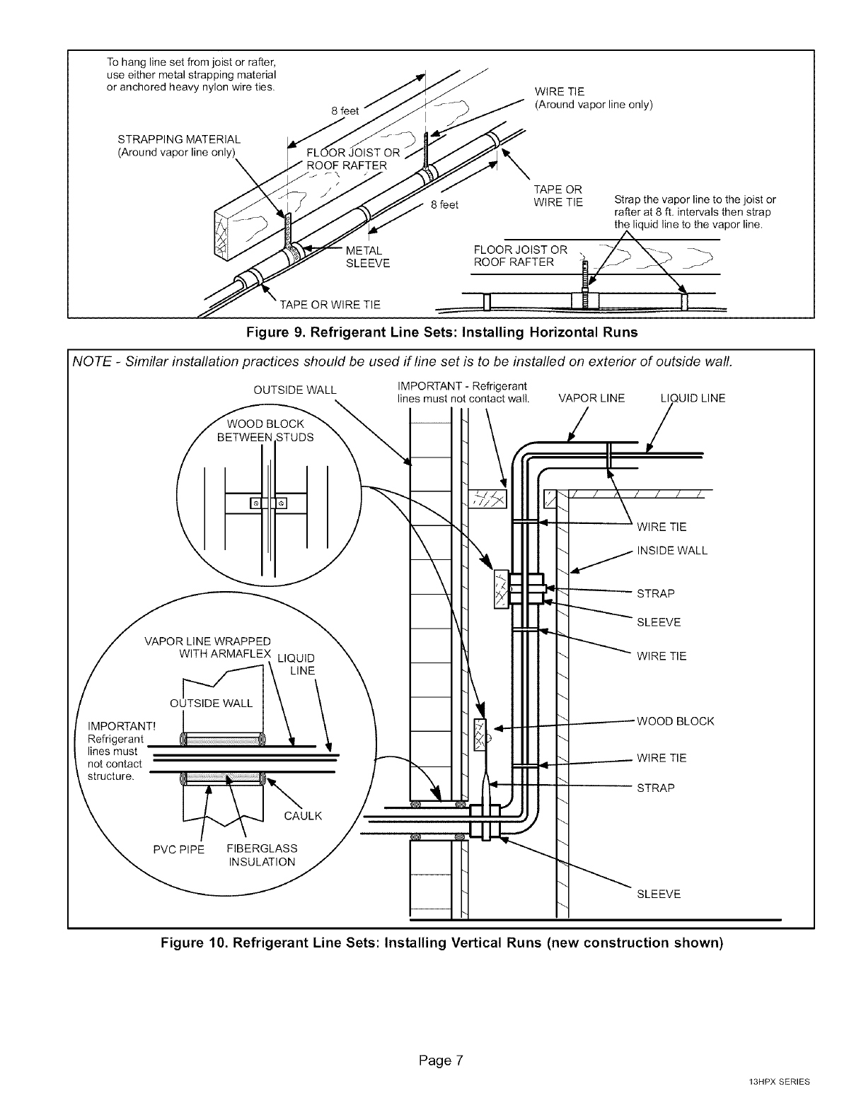
line set isolation. Figure 9 shows how to install line sets
on horizontal runs. Figure 10 shows how to install line
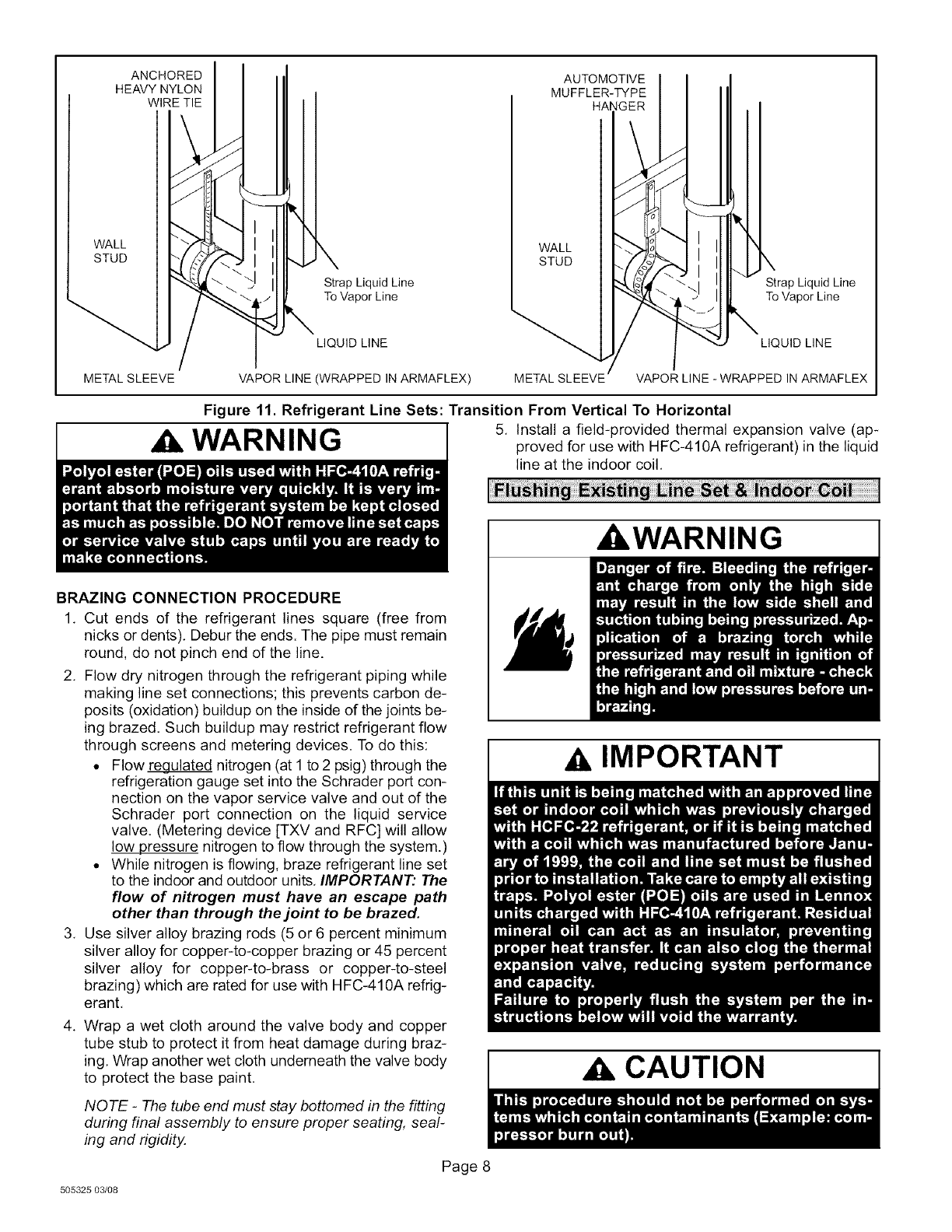
sets on vertical runs. Figure 11 shows how to make a
transition from horizontal to vertical.
505325 03/08
Page 6
To hang line set from joist or rafter,
use either metal strapping material
or anchored heavy nylon wire ties.
STRAPPING MATERIAL
(Around vapor line only)
8 feet
FLOOR JOIST OR
ROOF RAFTER
r\
WIRE TIE
(Around vapor line only)
TAPE OR
8 feet WIRE TIE
METAL FLOOR JOIST OR .
SLEEVE ROOF RAFTER
Strap the vapor line to the joist or
rafter at 8 ft. intervals then strap
the liquid line to the vapor line.
TAPE OR WIRE TIE
Figure 9. Refrigerant Line Sets: Installing Horizontal Runs
NOTE -Similar installation practices should be used if line set is to be installed on exterior of outside wall.
OUTSIDE WALL IMPORTANT - Refrigerant
lines must not contact wall. VAPOR LINE LI UID LINE
IMPORTANT!
Refrigerant
lines must
not contact
structure.
VAPOR LINE WRAPPED
\
CAULK
PVC PIPE FIBERGLASS
INSULATION
Figure 10. Refrigerant Line Sets: Installing Vertical Runs (new construction shown)
Page 7
13HPX SERIES
ANCHORED
HEAVY NYLON
WIRE TIE
AUTOMOTIVE
MUFFLER-TYPE
HANGER
WALL
STUD WALL
STUD
Strap Liquid Line
To Vapor Line
LIQUID LINE
Strap Liquid Line
To Vapor Line
LIQUID LINE
METAL SLEEVE VAPOR LINE (WRAPPED IN ARMAFLEX) VAPOR LINE -WRAPPED IN ARMAFLEX
Figure 11. Refrigerant Line Sets: Transition From Vertical To Horizontal
WARNING I 5, Install a field-provided thermal expansion valve (ap-proved for use with HFC-410A refrigerant) in the liquid
line at the indoor coil,
BRAZING CONNECTION PROCEDURE
1, Cut ends of the refrigerant lines square (free from
nicks or dents), Debur the ends. The pipe must remain
round, do not pinch end of the line.
2, Flow dry nitrogen through the refrigerant piping while
making line set connections; this prevents carbon de-
posits (oxidation) buildup on the inside of the joints be-
ing brazed. Such buildup may restrict refrigerant flow
through screens and metering devices. To do this:
• Flow_ulated nitrogen (at 1 to 2 psig) through the
refrigeration gauge set into the Schrader port con-
nection on the vapor service valve and out of the
Schrader port connection on the liquid service
valve. (Metering device [TXV and RFC] will allow
low pressure nitrogen to flow through the system.)
• While nitrogen is flowing, braze refrigerant line set
to the indoor and outdoor units, IMPORTANT." The
flow of nitrogen must have an escape path
other than through the joint to be brazed.
3, Use silver alloy brazing rods (5 or 6 percent minimum
silver alloy for copper-to-copper brazing or 45 percent
silver alloy for copper-to-brass or copper-to-steel
brazing) which are rated for use with HFC-410A refrig-
erant,
4. Wrap a wet cloth around the valve body and copper
tube stub to protect it from heat damage during braz-
ing, Wrap another wet cloth underneath the valve body
to protect the base paint,
NOTE -The tube end must stay bottomed in the fitting
during final assembly to ensure proper seating, seal-
ing and rigidity.
Page 8
505325 03/08
_WARNING
IMPORTANT
CAUTION
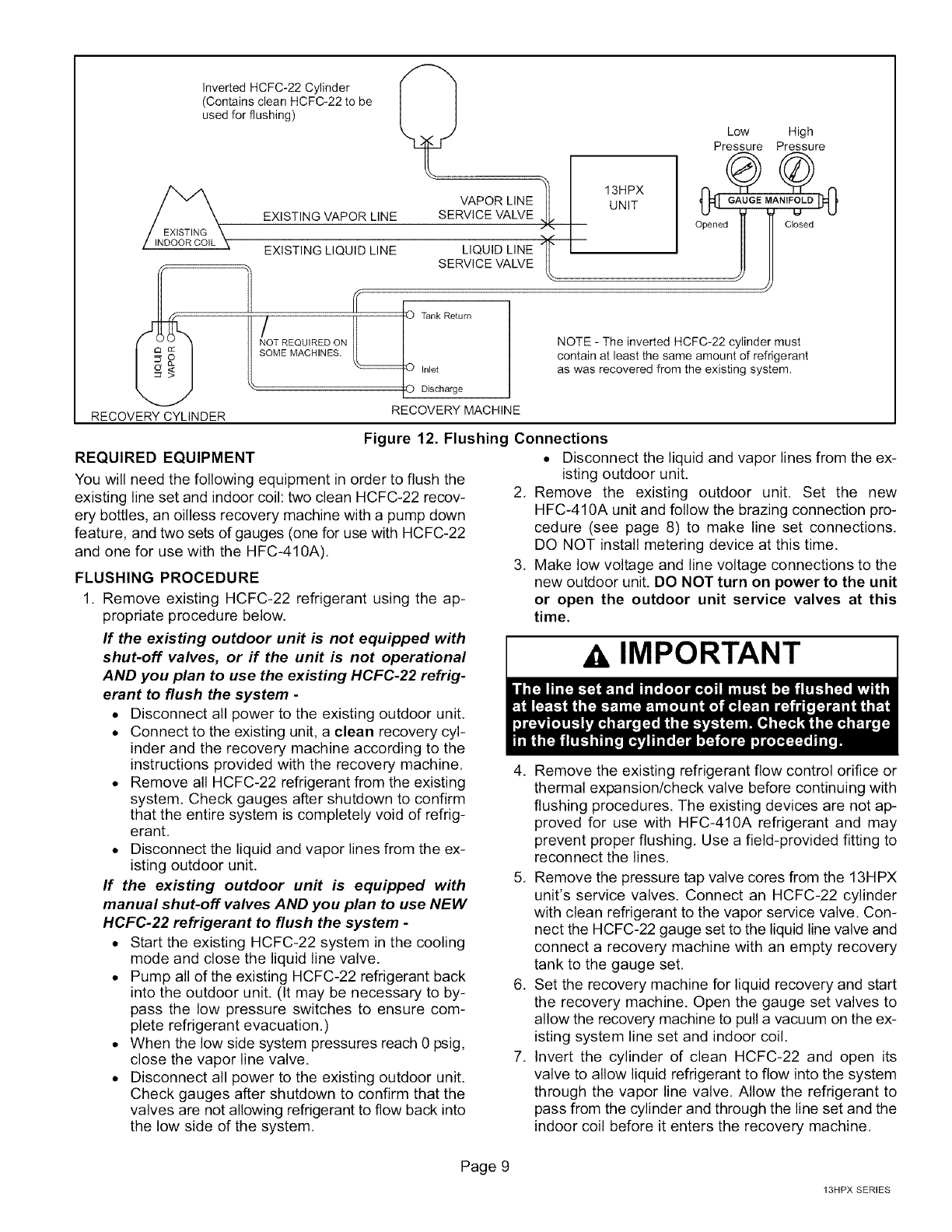
RECOVERY CYLINDER
Inverted HCFC-22 Cylinder
(Contains clean HCFC-22 to be
used for flushing)
EXISTING VAPOR LINE
VAPOR LINE
SERVICE VALVE
EXISTING LIQUID LINE LIQUID LINE
SERVICE VALVE
/ REOU,REDO. ank
SOME MACHINES.
Inlet
rDischarge
RECOVERY MACHINE
Low High
Pressure Pressure
NOTE - The inverted HCFC-22 cylinder must
contain at least the same amount of refrigerant
as was recovered from the existing system.
Figure 12. Flushing Connections
REQUIRED EQUIPMENT
You will need the following equipment in order to flush the
existing line set and indoor coil: two clean HCFC-22 recov-
ery bottles, an oilless recovery machine with a pump down
feature, and two sets of gauges (one for use with HCFC-22
and one for use with the HFC-410A).
FLUSHING PROCEDURE
1. Remove existing HCFC-22 refrigerant using the ap-
propriate procedure below.
If the existing outdoor unit is not equipped with
shut-off valves, or if the unit is not operational
AND you plan to use the existing HCFC-22 refrig-
erant to flush the system -
• Disconnect all power to the existing outdoor unit.
• Connect to the existing unit, a clean recovery cyl-
inder and the recovery machine according to the
instructions provided with the recovery machine.
• Remove all HCFC-22 refrigerant from the existing
system. Check gauges after shutdown to confirm
that the entire system is completely void of refrig-
erant.
• Disconnect the liquid and vapor lines from the ex-
isting outdoor unit.
If the existing outdoor unit is equipped with
manual shut-off valves AND you plan to use NEW
HCFC-22 refrigerant to flush the system -
• Start the existing HCFC-22 system in the cooling
mode and close the liquid line valve.
• Pump all of the existing HCFC-22 refrigerant back
into the outdoor unit. (It may be necessary to by-
pass the low pressure switches to ensure com-
plete refrigerant evacuation.)
• When the low side system pressures reach 0 psig,
close the vapor line valve.
• Disconnect all power to the existing outdoor unit.
Check gauges after shutdown to confirm that the
valves are not allowing refrigerant to flow back into
the low side of the system.
• Disconnect the liquid and vapor lines from the ex-
isting outdoor unit.
2. Remove the existing outdoor unit. Set the new
HFC-410A unit and follow the brazing connection pro-
cedure (see page 8) to make line set connections.
DO NOT install metering device at this time.
3. Make low voltage and line voltage connections to the
new outdoor unit. DO NOT turn on power to the unit
or open the outdoor unit service valves at this
time.
AIMPORTANT
4. Remove the existing refrigerant flow control orifice or
thermal expansion/check valve before continuing with
flushing procedures. The existing devices are not ap-
proved for use with HFC-410A refrigerant and may
prevent proper flushing, Use a field-provided fitting to
reconnect the lines.
5. Remove the pressure tap valve cores from the 13HPX
unit's service valves. Connect an HCFC-22 cylinder
with clean refrigerant to the vapor service valve. Con-
nect the HCFC-22 gauge set to the liquid line valve and
connect a recovery machine with an empty recovery
tank to the gauge set,
6. Set the recovery machine for liquid recovery and start
the recovery machine. Open the gauge set valves to
allow the recovery machine to pull a vacuum on the ex-
isting system line set and indoor coil.
7. Invert the cylinder of clean HCFC-22 and open its
valve to allow liquid refrigerant to flow into the system
through the vapor line valve. Allow the refrigerant to
pass from the cylinder and through the line set and the
indoor coil before it enters the recovery machine.
Page 9
13HPX SERIES
8. After all of the liquid refrigerant has been recovered,
switch the recovery machine to vapor recovery so that
all of the HCFC-22 vapor is recovered,
NOTE -A single system flush should remove all of the
mineral oil from the existing refrigerant lines and in-
door coil. A second flushing may be done (using clean
refrigerant) if insufficient amounts of mineral oil were
removed during the first flush. Each time the system
is flushed, you must allow the recovery machine
to pull a vacuum on the system at the end of the
procedure.
9. Close the valve on the inverted HCFC-22 drum and
the gauge set valves. Pump the remaining refrigerant
out of the recovery machine and turn the machine off,
10. Use dry nitrogen to break the vacuum on the refriger-
ant lines and indoor coil before removing the recovery
machine, gauges and HCFC-22 refrigerant drum. Re-
install pressure tap valve cores into 13HPX service
valves.
11. Install the provided check/expansion valve (approved
for use with HFC-410A refrigerant) in the liquid line at
the indoor coil.
13HPX units are used in check expansion valve (TXV) sys-
tems only, See the Lennox Engineering Handbook for ap-
proved TXV match-ups and application information.
NOTE -HFC-410A systems will not operate properly with
an HCFC-22 valve.
Check expansion valves equipped with Chatleff fittings are
available from Lennox. Refer to the Engineering Hand-
book for applicable check expansion valves for use with
specific match-ups, See table 3 for applicable check ex-
pansion valve kits,
Table 3. Indoor Check Expansion Valve Kits
Model Kit Number
13HPX-018, -024, -030, -036 49L24
13H PX-042, -048 49L25
13HPX-060 91M02
IMPORTANT
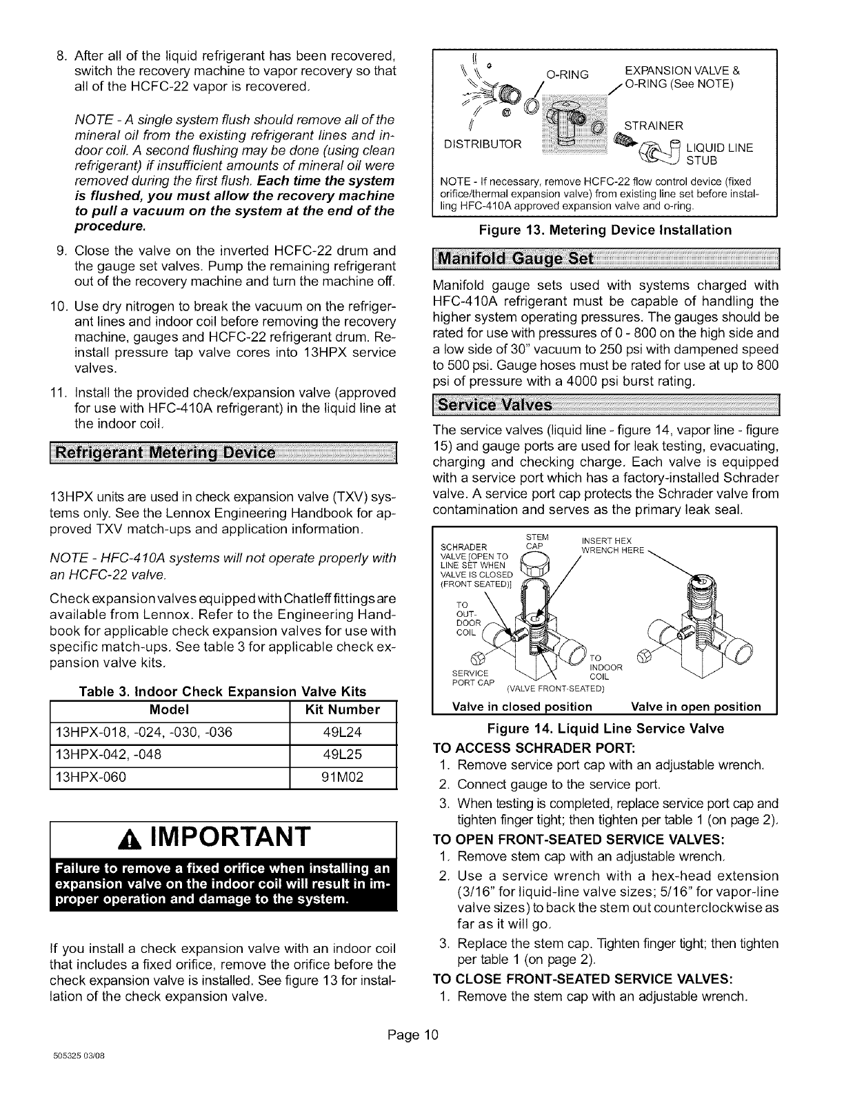
If you install a check expansion valve with an indoor coil
that includes a fixed orifice, remove the orifice before the
check expansion valve is installed. See figure 13 for instal-
lation of the check expansion valve.
/STRAINER
DISTRIBUTOR _"(_ LITQUBIDLINE
NOTE - If necessary, remove HCFC-22 flow control device (fixed
orifice/thermal expansion valve) from existing line set before instal-
ling HFC-410A approved expansion valve and o-ring,
Figure 13. Metering Device Installation
Manifold gauge sets used with systems charged with
HFC-410A refrigerant must be capable of handling the
higher system operating pressures, The gauges should be
rated for use with pressures of 0 - 800 on the high side and
a low side of 30" vacuum to 250 psi with dampened speed
to 500 psi. Gauge hoses must be rated for use at up to 800
psi of pressure with a 4000 psi burst rating,
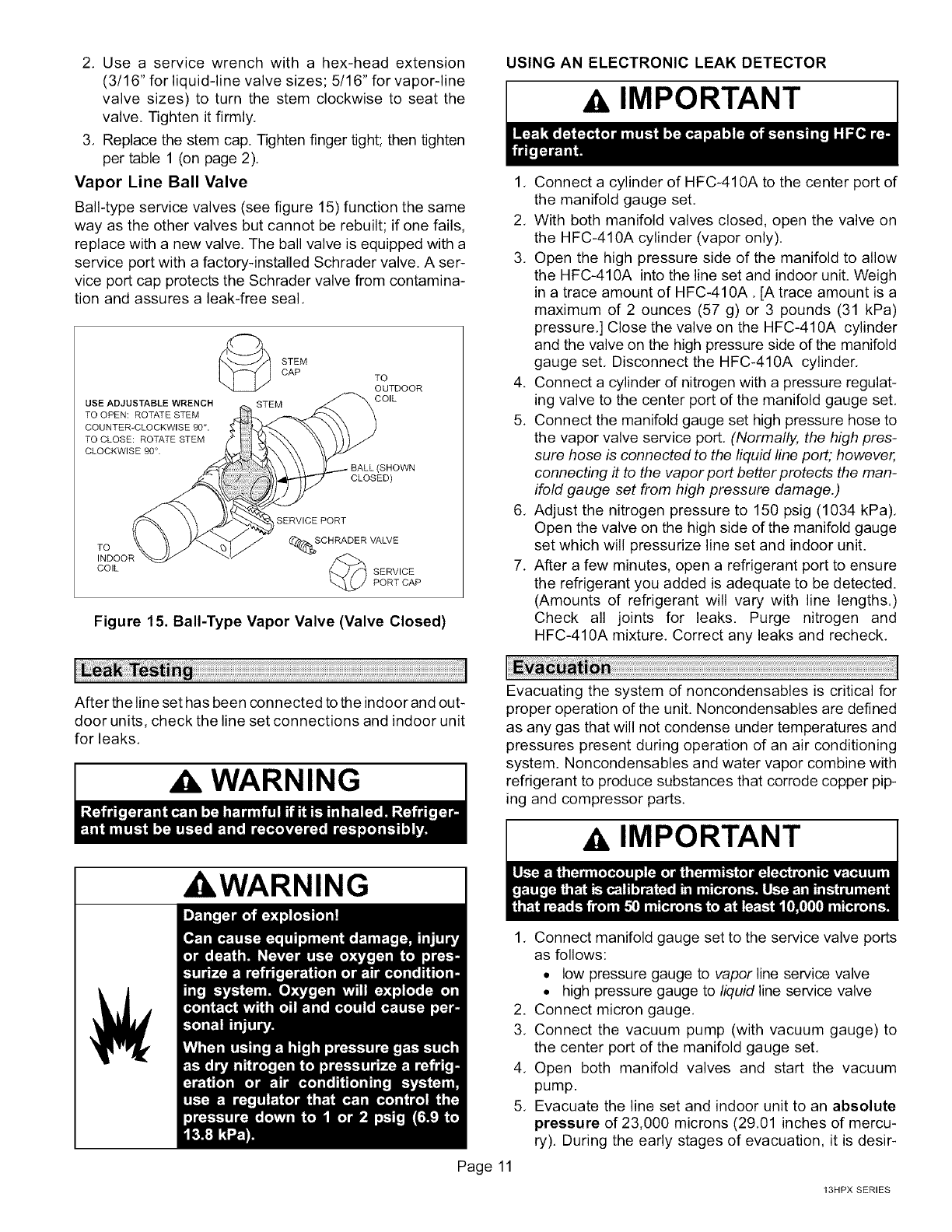
The service valves (liquid line - figure 14, vapor line - figure
15) and gauge ports are used for leak testing, evacuating,
charging and checking charge, Each valve is equipped
with a service port which has a factory-installed Schrader
valve. A service port cap protects the Schrader valve from
contamination and serves as the primary leak seal.
SCHRADER
VALVE [OPEN TO
LINE SET WHEN
VALVE IS CLOSED
]FRONT SEATED)]
TO
OUT-
STEM INSERT HEX
CAP
_TO
INDOOR
SERVICE COIL
PORT CAP ]VALVE FRON%SEATED)
Valve in closed position Valve in open position
Figure 14. Liquid Line Service Valve
TO ACCESS SCHRADER PORT:
1. Remove service port cap with an adjustable wrench,
2. Connect gauge to the service port,
3. When testing is completed, replace service port cap and
tighten finger tight; then tighten per table 1 (on page 2).
TO OPEN FRONT-SEATED SERVICE VALVES:
1, Remove stem cap with an adjustable wrench,
2. Use a service wrench with a hex-head extension
(3/16" for liquid-line valve sizes; 5/16" for vapor-line
valve sizes) to back the stem out counterclockwise as
far as it will go,
3. Replace the stem cap. Tighten finger tight; then tighten
per table 1 (on page 2).
TO CLOSE FRONT-SEATED SERVICE VALVES:
1. Remove the stem cap with an adjustable wrench.
505325 03/08
Page 10
2, Usea servicewrenchwitha hex-headextension
(3/16"forliquid-linevalvesizes;5/16"forvapor-line
valvesizes)to turnthestemclockwiseto seatthe
valve.Tightenitfirmly,
3, Replacethestemcap.Tightenfingertight;thentighten
pertable1(onpage2),
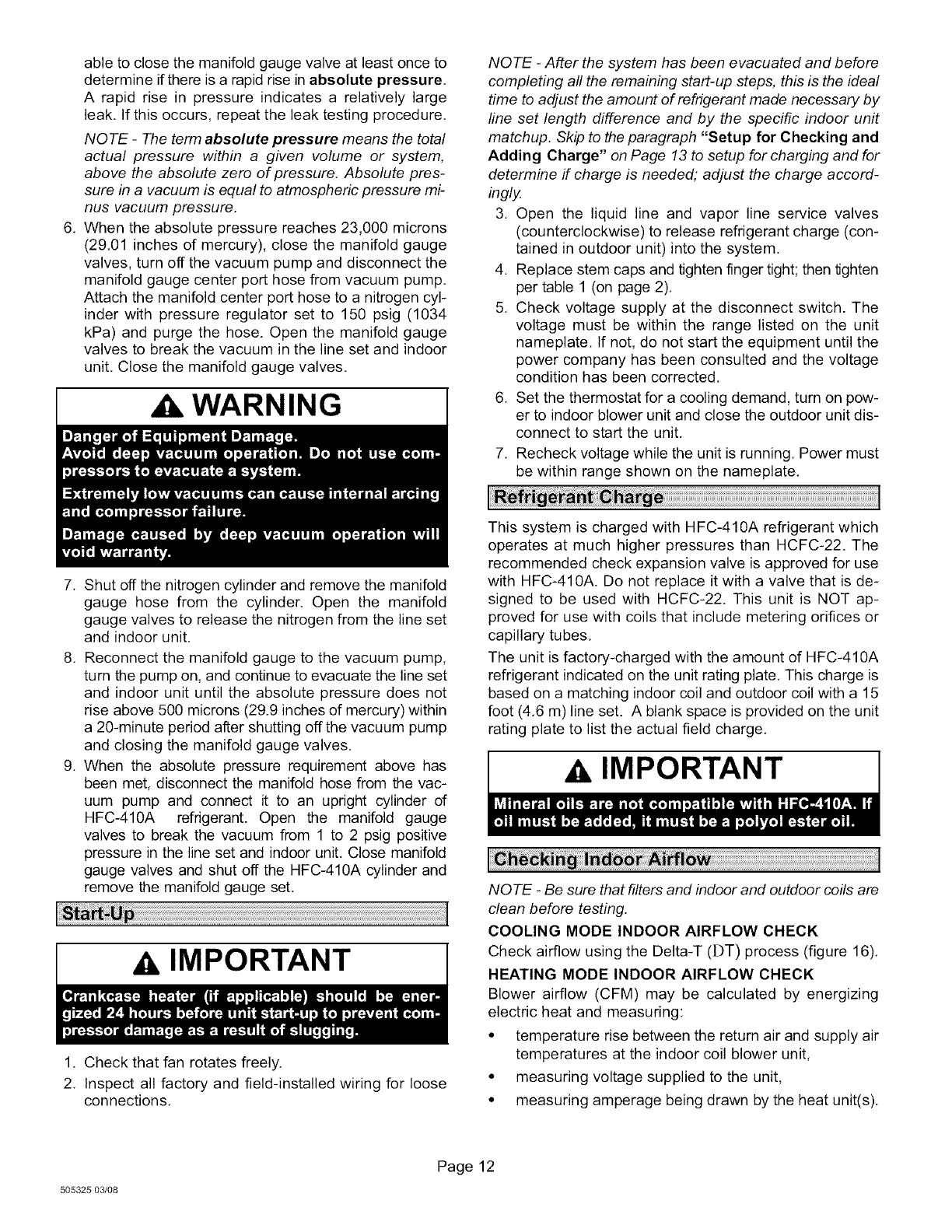
Vapor Line Ball Valve
Ball-typeservicevalves(seefigure15)functionthesame
wayastheothervalvesbutcannotberebuilt;if onefails,
replacewithanewvalve,Theballvalveisequippedwitha
serviceportwithafactory-installedSchradervalve.Aser-
viceportcapprotectstheSchradervalvefromcontamina-
tionandassuresa leak-freeseal,
STEM
CAP TO
OUTDOOR
USE ADJUSTABLE WRENCH _,,. STEM _(STEM COIL
TO OPEN: ROTATE STEM__.,__
COUNTER-CLOCKWISE 90° .
TO CLOSE: ROTATE STEM
CLOCKWISE 90 °.
(SHOWN
CLOSED)
TO
INDOOR _ _""
COIL SERVICE
PORT CAP
Figure 15. Bali-Type Vapor Valve (Valve Closed)
USING AN ELECTRONIC LEAK DETECTOR
IMPORTANT
1, Connect a cylinder of HFC-410A to the center port of
the manifold gauge set.
2, With both manifold valves closed, open the valve on
the HFC-410A cylinder (vapor only).
3, Open the high pressure side of the manifold to allow
the HFC-410A into the line set and indoor unit. Weigh
in a trace amount of HFC-410A, [A trace amount is a
maximum of 2 ounces (57 g) or 3 pounds (31 kPa)
pressure,] Close the valve on the HFC-410A cylinder
and the valve on the high pressure side of the manifold
gauge set, Disconnect the HFC-410A cylinder,
4. Connect a cylinder dnitrogen with a pressure regulat-
ing valve to the center port of the manifold gauge set,
5. Connect the manifold gauge set high pressure hose to
the vapor valve service port. (Normally, the high pres-
sure hose is connected to the liquid line port; however,
connecting it to the vapor port better protects the man-
ifold gauge set from high pressure damage.)
6, Adjust the nitrogen pressure to 150 psig (1034 kPa),
Open the valve on the high side of the manifold gauge
set which will pressurize line set and indoor unit.
7, After a few minutes, open a refrigerant port to ensure
the refrigerant you added is adequate to be detected.
(Amounts of refrigerant will vary with line lengths.)
Check all joints for leaks. Purge nitrogen and
HFC-410A mixture, Correct any leaks and recheck,
After the line set has been connected to the indoor and out-
door units, check the line set connections and indoor unit
for leaks.
WARNING
_WARNING
Evacuating the system of noncondensables is critical for
proper operation of the unit. Noncondensables are defined
as any gas that will not condense under temperatures and
pressures present during operation of an air conditioning
system. Noncondensables and water vapor combine with
refrigerant to produce substances that corrode copper pip-
ing and compressor parts.
AIMPORTANT
Page 11
1, Connect manifold gauge set to the service valve ports
as follows:
•low pressure gauge to vapor line service valve
• high pressure gauge to liquid line service valve
2. Connect micron gauge.
3, Connect the vacuum pump (with vacuum gauge) to
the center port of the manifold gauge set,
4, Open both manifold valves and start the vacuum
pump.
5, Evacuate the line set and indoor unit to an absolute
pressure of 23,000 microns (29,01 inches of mercu-
ry). During the early stages of evacuation, it is desir-
13HPX SERIES
able to close the manifold gauge valve at least once to
determine if there is a rapid rise in absolute pressure,
A rapid rise in pressure indicates a relatively large
leak, If this occurs, repeat the leak testing procedure,
NOTE -The term absolute pressure means the total
actual pressure within a given volume or system,
above the absolute zero of pressure. Absolute pres-
sure in a vacuum is equal to atmospheric pressure mi-
nus vacuum pressure.
6, When the absolute pressure reaches 23,000 microns
(29.01 inches of mercury), close the manifold gauge
valves, turn off the vacuum pump and disconnect the
manifold gauge center port hose from vacuum pump.
Attach the manifold center port hose to a nitrogen cyl-
inder with pressure regulator set to 150 psig (1034
kPa) and purge the hose. Open the manifold gauge
valves to break the vacuum in the line set and indoor
unit, Close the manifold gauge valves,
WARNING I
NOTE -After the system has been evacuated and before
completing all the remaining start-up steps, this is the ideal
time to adjust the amount of refrigerant made necessary by
line set length difference and by the specific indoor unit
matchup. Skip to the paragraph "Setup for Checking and
Adding Charge" on Page 13 to setup for charging and for
determine if charge is needed; adjust the charge accord-
ingly
3, Open the liquid line and vapor line service valves
(counterclockwise) to release refrigerant charge (con-
tained in outdoor unit) into the system,
4, Replace stem caps and tighten finger tight; then tighten
per table 1 (on page 2),
5, Check voltage supply at the disconnect switch. The
voltage must be within the range listed on the unit
nameplate. If not, do not start the equipment until the
power company has been consulted and the voltage
condition has been corrected.
6, Set the thermostat for a cooling demand, turn on pow-
er to indoor blower unit and close the outdoor unit dis-
connect to start the unit,
7, Recheck voltage while the unit is running. Power must
be within range shown on the nameplate,
7. Shut off the nitrogen cylinder and remove the manifold
gauge hose from the cylinder. Open the manifold
gauge valves to release the nitrogen from the line set
and indoor unit.
8. Reconnect the manifold gauge to the vacuum pump,
turn the pump on, and continue to evacuate the line set
and indoor unit until the absolute pressure does not
rise above 500 microns (29.9 inches of mercury) within
a 20-minute period after shutting off the vacuum pump
and closing the manifold gauge valves.
9. When the absolute pressure requirement above has
been met, disconnect the manifold hose from the vac-
uum pump and connect it to an upright cylinder d
HFC-410A refrigerant. Open the manifold gauge
valves to break the vacuum from 1 to 2 psig positive
pressure in the line set and indoor unit, Close manifold
gauge valves and shut off the HFC-410A cylinder and
remove the manifold gauge set,
AIMPORTANT
1. Check that fan rotates freely.
2. Inspect all factory and field-installed wiring for loose
connections.
This system is charged with HFC-410A refrigerant which
operates at much higher pressures than HCFC-22. The
recommended check expansion valve is approved for use
with HFC-410A. Do not replace it with a valve that is de-
signed to be used with HCFC-22. This unit is NOT ap-
proved for use with coils that include metering orifices or
capillary tubes,
The unit is factory-charged with the amount of HFC-410A
refrigerant indicated on the unit rating plate, This charge is
based on a matching indoor coil and outdoor coil with a 15
foot (4,6 m) line set. A blank space is provided on the unit
rating plate to list the actual field charge,
AIMPORTANT
NOTE -Be sure that filters and indoor and outdoor coils are
clean before testing.
COOLING MODE INDOOR AIRFLOW CHECK
Check airflow using the Delta-T (DT) process (figure 16),
HEATING MODE INDOOR AIRFLOW CHECK
Blower airflow (CFM) may be calculated by energizing
electric heat and measuring:
• temperature rise between the return air and supply air
temperatures at the indoor coil blower unit,
• measuring voltage supplied to the unit,
• measuring amperage being drawn by the heat unit(s),
505325 03/08
Page 12
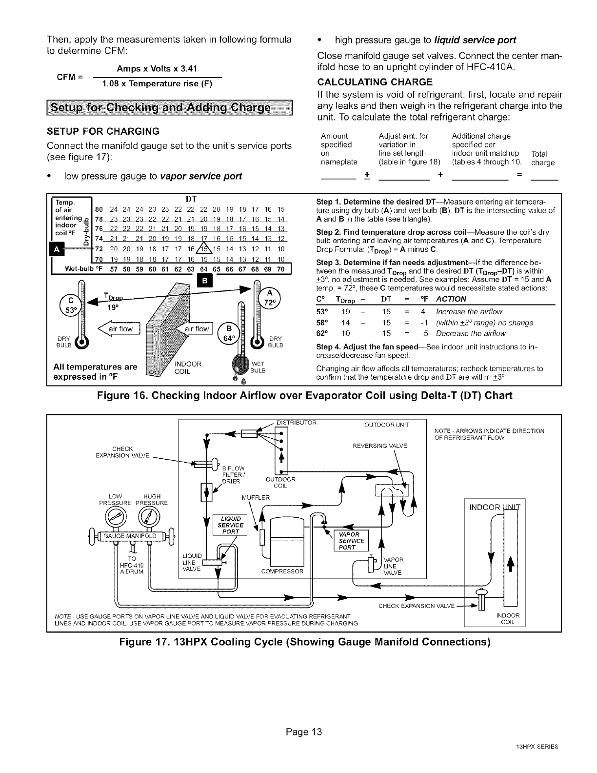
Then,applythemeasurementstakeninfollowingformula
todetermineCFM:
Amps x Volts x 3.41
CFM =1.08 x Temperature rise (F)
SETUP FOR CHARGING
Connect the manifold gauge set to the unit's service ports
(see figure 17):
•low pressure gauge to vapor service port
• high pressure gauge to liquid service port
Close manifold gauge set valves. Connect the center man-
ifold hose to an upright cylinder of HFC-410A,
CALCULATING CHARGE
If the system is void of refrigerant, first, locate and repair
any leaks and then weigh in the refrigerant charge into the
unit, To calculate the total refrigerant charge:
Amount Adjust amt. for Additional charge
specified variation in specified per
on line set length indoor unit matchup Total
nameplate (table in figure 18) (tables 4 through 10 charge
+ + =
Temp. ]
of air I80
entering j= I 78
indoor _1 ==
IcoiI°F _1 .u
IWet-bulb °F
I)T
24 24 24 23 23 22 22 22 20 19 18 17 16 15
23 23 23 22 22 21 21 20 19 18 17 16 15 14
22 22 22 21 21 20 19 19 18 17 16 15 14 13
21 21 21 20 19 19 18 17 16 16 15 14 13 12
20 20 19 18 17 17 161L_15 14 13 12 11 10
19 19 18 18 17 17 16 15 15 14 13 12 11 10
I
57 58 59 60 61 62 63 64 65 66 67 68 69 70 I
DRY
I
BULB
iNDOOR 1 WET
COIL BULB
Step 1. Determine the desired DT--Measure entering air tempera-
ture using dry bulb (A) and wet bulb (B) DT is the intersecting value of
A and B in the table (see triangle).
Step 2. Find temperature drop across coil--Measure the coil's dry
bulb entering and leaving air temperatures (A and C). Temperature
Drop Formula: (TDrop) = A minus C.
Step 3. Determine if fan needs adjustment--If the difference be-
tween the measured TDrop and the desired ])T (TDropiDT) is within
+3°, no adjustment is needed, See examples: Assume ])T = 15 and A
temp. = 72 °, these C temperatures would necessitate stated actions:
C° TDrop- DT = °F ACTION
53°19 - 15 = 4 Increase the airflow
58° 14 - 15 = -1 (within +3 ° range) no change
62°10 - 15 = -5 Decrease the airflow
Step 4. Adjust the fan speed--See indoor unit instructions to in-
crease/decrease fan speed
Changing air flow affects all temperatures; recheck temperatures to
confirm that the temperature drop and DT are within +3o
Figure 16. Checking Indoor Airflow over Evaporator Coil using Delta-T (DT) Chart
OUTDOOR UNIT
CHECK
EXPANSION VALVE __,.,.,.,._
LOW HUGH
PRESSURE PRESSURE I
LIQUID
LINE I
VALVE
DISTRIBUTOR
0_ BIFLO
FILTER /
DRIER OUTDOOR
CO,L
MUFFLER
SERV
COMPRESSOR
t
NOTE -ARROWS INDICATE DIRECTION
OF REFRIGERANT FLOW
REVERSING VALVE
Q APOR
LINE
VALVE
CHECK EXPANSION VALVE i
NOTE- USE GAUGE PORTS ON VAPOR LINE VALVE AND LIQUID VALVE FOR EVACUATING REFRIGERANT
LINES AND INDOOR COIL. USE VAPOR GAUGE PORT TO MEASURE VAPOR PRESSURE DURING CHARGING.
INDOOR_INI
/,-'-1
:11"-"""""4
--'ll"l I I
INDOOR
COIL
Figure 17. 13HPX Cooling Cycle (Showing Gauge Manifold Connections)
Page13
13HPX SERIES
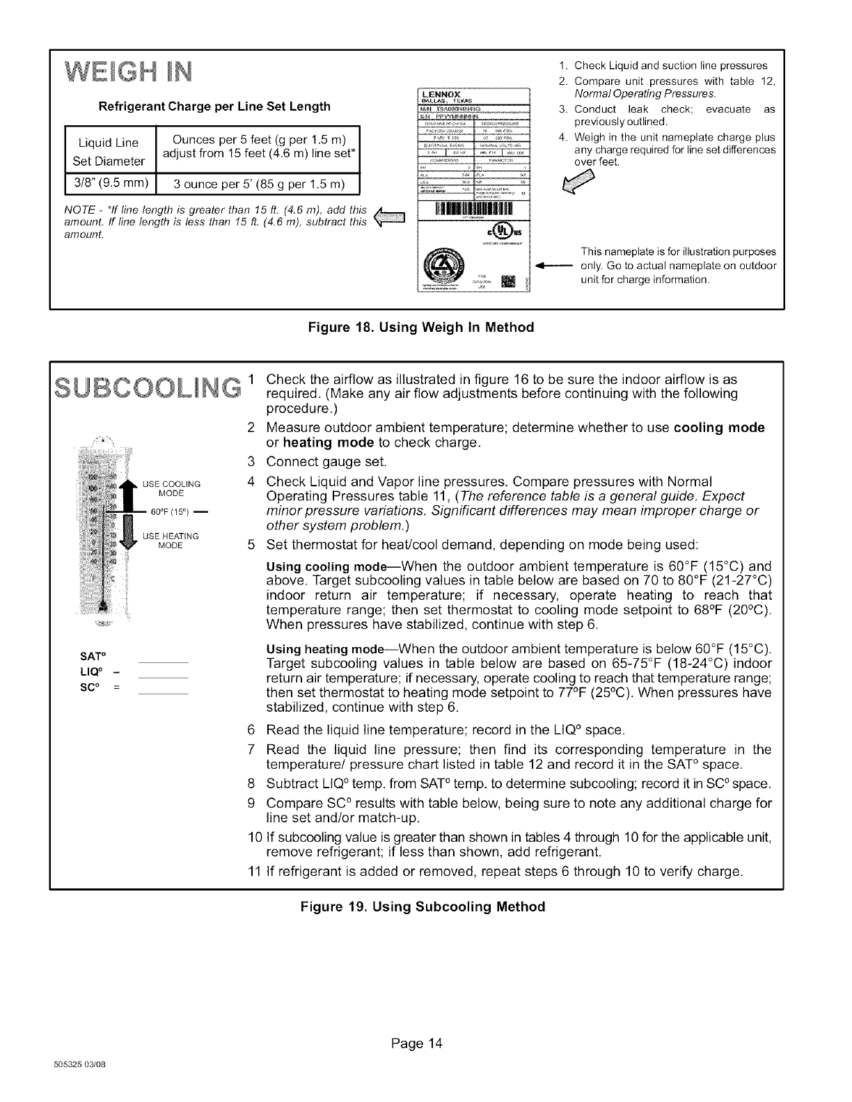
WE)GH )N
RefrigerantCharge per Line Set Length
Liquid Line Ounces per 5 feet (g per 1.5 m)
Set Diameter adjust from 15feet (4.6 m) lineset*
3t8" (9.5 mm) 3 ounce per 5' (85 g per 1.5 m)
NOTE - *If line length is greater than 15 ft. (4.6 m), add this
amount. If line length is less than 15 ft. (4.6 m), subtract this
amount.
LENNOX
HIm!!)HiilII|
1. Check Liquid and suction line pressures
2. Compare unit pressures with table 12,
Normal Operating Pressures.
3. Conduct leak check; evacuate as
previously outlined.
4. Weigh in the unit nameplate charge plus
any charge required for line set differences
over feet,
This nameplate is for illustration purposes
only. Go to actual nameplate on outdoor
unit for charge information.
Figure 18. Using Weigh In Method
SUBCOOUNG 1
):))_);),
USE COOLING
MODE
60°F {15 °) --
USE HEATING
MODE
2
3
4
SATo
LIQ o -
SC o =
Check the airflow as illustrated in figure 16 to be sure the indoor airflow is as
required. (Make any air flow adjustments before continuing with the following
procedure.)
Measure outdoor ambient temperature; determine whether to use cooling mode
or heating mode to check charge.
Connect gauge set.
Check Liquid and Vapor line pressures. Compare pressures with Normal
Operating Pressures table 11, (The reference table is a general guide. Expect
minor pressure variations. Significant differences may mean improper charge or
other system problem.)
Set thermostat for heat/cool demand, depending on mode being used:
Using cooling mode--When the outdoor ambient temperature is 60°F (15°C) and
above. Target subcooling values in table below are based on 70 to 80°F (21-27°C)
indoor return air temperature; if necessary, operate heating to reach that
temperature range; then set thermostat to cooling mode setpoint to 68°F (20°C).
When pressures have stabilized, continue with step 6.
Using heating mode--When the outdoor ambient temperature is below 60°F (15°C).
Target subcooling values in table below are based on 65-75°F (18-24°C)indoor
return air temperature; if necessary, operate cooling to reach that temperature range;
then set thermostat to heating mode setpoint to 77°F (25°C). When pressures have
stabilized, continue with step 6.
6 Read the liquid line temperature; record in the LIQ° space.
7 Read the liquid line pressure; then find its corresponding temperature in the
temperature/pressure chart listed in table 12 and record it in the SAT° space.
8 Subtract LIQ° temp. from SAT° temp. to determine subcooling; record it in SC°space.
9 Compare SC° results with table below, being sure to note any additional charge for
line set and/or match-up.
10 If subcooling value is greater than shown in tables 4 through 10 for the applicable unit,
remove refrigerant; if less than shown, add refrigerant.
11 If refrigerant is added or removed, repeat steps 6 through 10 to verify charge.
Figure 19. Using Subcooling Method
505325 03/08
Page 14
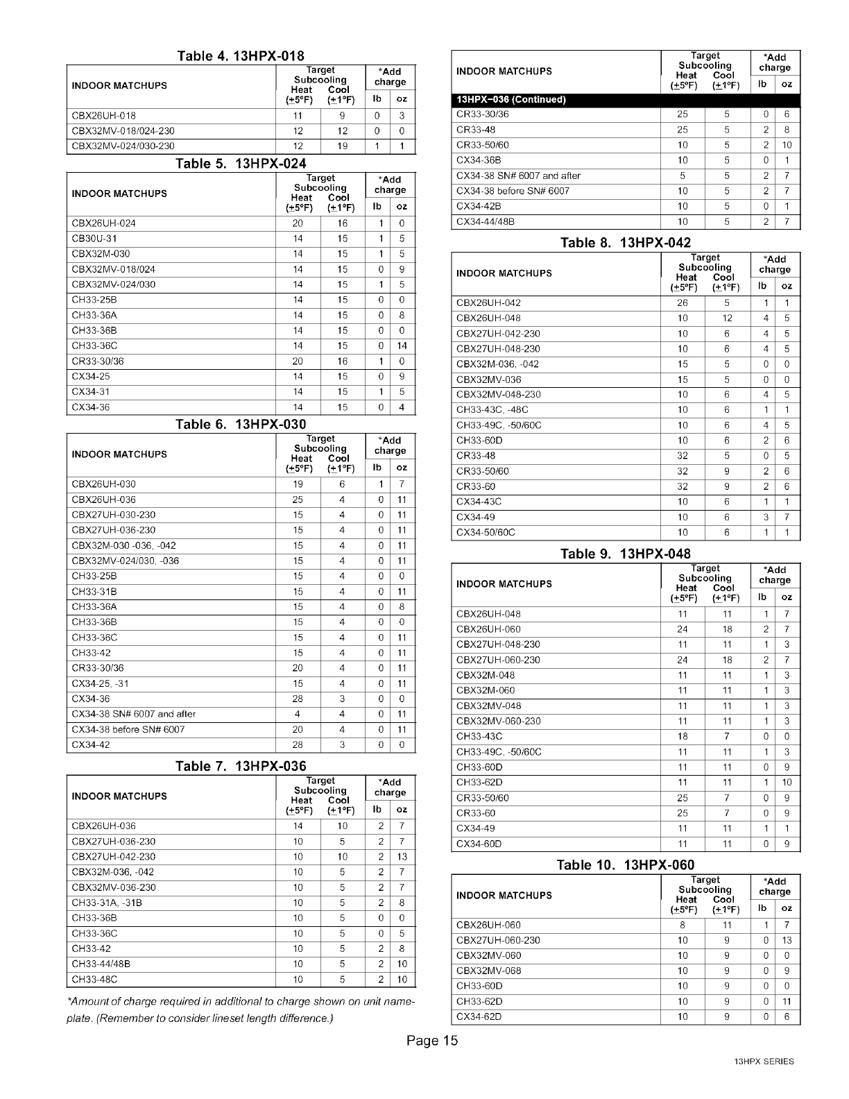
Table 4. 13HPX-018
Target *Add
Subcooling charge
INDOOR MATCHUPS Heat Cool
(+5OF) (+1OF) Ib oz
CBX26UH-018 11 9 0 3
CBX32MV-O 18/024-230 12 12 O O
CBX32MV-024/030-230 12 19 1 1
Table 5. 13HPX-024
Target *Add
Subcooling charge
INDOOR MATCHUPS Heat Cool
(+5OF) (+1OF) Ib oz
CBX26UH-024 20 16 1 O
CB3OU-31 14 15 1 5
CBX32M-030 14 15 1 5
CBX32MV-O 18/024 14 15 O 9
CBX32MV-024/030 14 15 1 5
CH33-25B 14 15 O O
CH33-36A 14 15 O 8
CH33-36B 14 15 O O
CH33-36C 14 15 O 14
CR33-30/36 20 16 1 O
CX34-25 14 15 O 9
CX34-31 14 15 1 5
CX34-36 14 15 O 4
Table 6. 13HPX-030
Target *Add
Subcooling charge
INDOOR MATCHUPS Heat Cool
(+5OF) (+1OF) Ib oz
CBX26UH-030 19 6 1 7
CBX26UH-036 25 4 O 11
CBX27UH-030-230 15 4 O 11
CBX27UH-036-230 15 4 O 11
CBX32M-030 -036, -042 15 4 O 11
CBX32MV-024/030, -036 15 4 O 11
CH33-25B 15 4 O O
CH33-31B 15 4 O 11
CH33-36A 15 4 O 8
CH33-36B 15 4 O O
CH33-36C 15 4 O 11
CH33-42 15 4 O 11
CR33-30/36 20 4 O 11
CX34-25, -31 15 4 O 11
CX34-36 28 3 O O
CX34-38 SN# 6007 and after 4 4 O 11
CX34-38 before SN# 6007 20 4 O 11
CX34-42 28 3 O O
Table 7. 13HPX-036
Target
Subcooling
INDOOR MATCHUPS Heat Cool
(+5°F) (+I°F)
CBX26UH-036 14 10
CBX27UH-036-230 10 5
CBX27UH-042-230 10 10
CBX32M-036, -042 10 5
CBX32MV-036-230 10 5
CH33-31A, -31B 10 5
CH33-36B 10 5
CH33-36C 10 5
CH33-42 10 5
CH33-44/48B 10
C H33-48C 10 5
*Amount of charge required in additional to charge shown
plate. (Remember to consider lineset length difference.)
*Add
charge
Ib oz
2 7
2 7
2 13
2 7
2 7
2 8
0 0
0 5
2 8
5 2 10
2 10
on unit name-
Target *Add
Subcooling charge
INDOOR MATCHUPS Heat Cool
(+5OF) (+1OF) Ib oz
CR33-30/36 25 5 0 6
CR33-48 25 5 2 8
CR33-50/60 10 5 2 10
CX34-36B 10 5 0 1
CX34-38 SN# 6007 and after 5 5 2 7
CX34-38 before SN# 6007 10 5 2 7
CX34-42B 10 5 0 1
CX34-44/48B 10 5 2 7
Table 8. 13HPX-042
Target *Add
Subcooling charge
INDOOR MATCHUPS Heat Cool
(+5OF) (+1OF) Ib oz
CBX26UH-042 26 5 1 1
CBX26UH-048 10 12 4 5
CBX27UH-042-230 10 6 4 5
CBX27UH-048-230 10 6 4 5
CBX32M-036, -042 15 5 O O
CBX32MV-036 15 5 O O
CBX32MV-048-230 10 6 4 5
CH33-43C, -48C 10 6 1 1
CH33-49C, -50/60C 10 6 4 5
CH33-6OD 10 6 2 6
CR33-48 32 5 O 5
CR33-50/60 32 9 2 6
CR33-60 32 9 2 6
CX34-43C 10 6 1 1
CX34-49 10 6 3 7
CX34-50/60C 10 6 1 1
Table 9. 13HPX-048
Target *Add
Subcooling charge
INDOOR MATCHUPS Heat Cool
(+5OF) (+1OF) Ib oz
CBX26UH-048 11 11 1 7
CBX26UH-060 24 18 2 7
CBX27UH-048-230 11 11 1 3
CBX27UH-060-230 24 18 2 7
CBX32M-048 11 11 1 3
CBX32M-060 11 11 1 3
CBX32MV-048 11 11 1 3
CBX32MV-060-230 11 11 1 3
CH33-43C 18 7 O O
CH33-49C, -50/60C 11 11 1 3
CH33-6OD 11 11 O 9
CH33-62D 11 11 1 10
CR33-50/60 25 7 O 9
CR33-60 25 7 O 9
CX34-49 11 11 1 1
CX34-6OD 11 11 O 9
Table 10. 13HPX-060
Target *Add
Subcooling charge
INDOOR MATCHUPS Heat Cool
(+5OF) (+1OF) Ib oz
CBX26UH-060 8 11 1 7
CBX27UH-060-230 10 9 O 13
CBX32MV-060 10 9 O O
CBX32MV-068 10 9 O 9
CH33-6OD 10 9 O O
CH33-62D 10 9 O 11
CX34-62D 10 9 O 6
Page15
13HPX SERIES
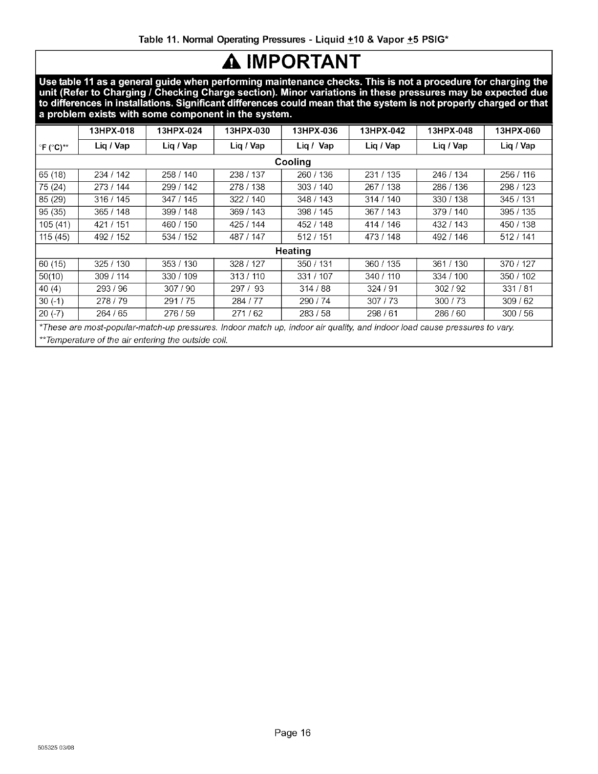
Table 11. Normal Operating Pressures - Liquid +10 & Vapor +5 PSIG*
Ak IMPORTANT
13HPX-018 13HPX-024 13HPX-030 13HPX-036 13HPX-042 13HPX-048 13HPX-060
°F(°C)** Liq /Vap Liq /Vap Liq /Vap Liq /Vap Liq /Vap Liq /Vap Liq /Vap
Cooling
65 (18) 234/142 258/140 238/137 260/136 231 /135 246/134 256/ 116
75 (24) 273 /144 299 /142 278 /138 303 /140 267 /138 286 /136 298 /123
85 (29) 316 /145 347 /145 322 /140 348 /143 314 /140 330 /138 345 /131
95 (35) 365 /148 399 /148 369 /143 398 /145 367 /143 379 /140 395 /135
105 (41) 421 /151 460 /150 425 /144 452 /148 414 /146 432 /143 450 /138
115 (45) 492 /152 534 /152 487 /147 512 /151 473 /148 492 /146 512 /141
Heating
60 (15) 325 /130 353 /130 328 /127 350 /131 360 /135 361 /130 370 /127
50(10) 309/114 330/109 313/ 110 331 /107 340/ 110 334/100 350/102
40 (4) 293 /96 307 /90 297 /93 314 /88 324 /91 302 /92 331 /81
30 (-1) 278 /79 291 /75 284 /77 290 /74 307 /73 300 /73 309 /62
20 (-7) 264 /65 276 /59 271 /62 283 /58 298 /61 286 /60 300 /56
*These are most-popular-match-up pressures. Indoor match up, indoor air quafity, and indoor load cause pressures to vary
**Temperature of the air entering the outside coil.
505325 03/08
Page 16
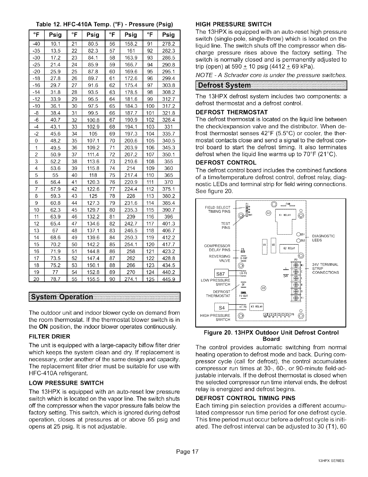
Table 12. HFC-410A Temp. (°F) - Pressure (Psig)
°F Psig °F Psig °F Psig °F Psig
-40 10.1 21 80.5 56 158.2 91 278.2
-35 13.5 22 82.3 57 161 92 282.3
-30 17.2 23 84.1 58 163.9 93 286.5
-25 21.4 24 85.9 59 166.7 94 290.8
-20 25.9 25 87.8 60 169.6 95 295.1
-18 27.8 26 89.7 61 172.6 96 299.4
-16 29.7 27 91.6 62 175.4 97 303.8
-14 31.8 28 93.5 63 178.5 98 308.2
-12 33.9 29 95.5 64 181.6 99 312.7
-10 36.1 30 97.5 65 184.3 100 317.2
-8 38.4 31 99.5 66 187.7 101 321.8
-6 40.7 32 100.8 67 190.9 102 326.4
-4 43.1 33 102.9 68 194.1 103 331
-2 45.6 34 105 69 197.3 104 335.7
0 48.2 35 107.1 70 200.6 105 340.5
1 49.5 36 109.2 71 203.9 106 345.3
2 50.9 37 111.4 72 207.2 107 350.1
3 52.2 38 113.6 73 210.6 108 355
4 53.6 39 115.8 74 214 109 360
5 55 40 118 75 217.4 110 365
6 56.4 41 120.3 76 220.9 111 370
7 57.9 42 122.6 77 224.4 112 375.1
8 59.3 43 125 78 228 113 380.2
9 60.8 44 127.3 79 231.6 114 385.4
10 62.3 45 129.7 80 235.3 115 390.7
11 63.9 46 132.2 81 239 116 396
12 65.4 47 134.6 82 242.7 117 401.3
13 67 48 137.1 83 246.5 118 406.7
14 68.6 49 139.6 84 250.3 119 412.2
15 70.2 50 142.2 85 254.1 120 417.7
16 71.9 51 144.8 86 258 121 423.2
17 73.5 52 147.4 87 262 122 428.8
18 75.2 53 150.1 88 266 123 434.5
19 77 54 152.8 89 270 124 440.2
20 78.7 55 155.5 90 274.1 125 445.9
The outdoor unit and indoor blower cycle on demand from
the room thermostat. If the thermostat blower switch is in
the ON position, the indoor blower operates continuously.
FILTER DRIER
The unit is equipped with a large-capacity biflow filter drier
which keeps the system clean and dry. If replacement is
necessary, order another of the same design and capacity.
The replacement filter drier must be suitable for use with
HFC-410A refrigerant.
LOW PRESSURE SWITCH
The 13HPX is equipped with an auto-reset low pressure
switch which is located on the vapor line. The switch shuts
off the compressor when the vapor pressure falls below the
factory setting. This switch, which is ignored during defrost
operation, closes at pressures at or above 55 psig and
opens at 25 psig. It is not adjustable.
HIGH PRESSURE SWITCH
The 13HPX is equipped with an auto-reset high pressure
switch (single-pole, single-throw) which is located on the
liquid line, The switch shuts off the compressor when dis-
charge pressure rises above the factory setting. The
switch is normally closed and is permanently adjusted to
trip (open) at 590 _+10 psig (4412 _+69 kPa),
NOTE -A Schrader core is under the pressure switches.
The 13HPX defrost system includes two components: a
defrost thermostat and a defrost control.
DEFROST THERMOSTAT
The defrost thermostat is located on the liquid line between
the check/expansion valve and the distributor. When de-
frost thermostat senses 42°F (5.5°C) or cooler, the ther-
mostat contacts close and send a signal to the defrost con-
trol board to start the defrost timing. It also terminates
defrost when the liquid line warms up to 70°F (21°C).
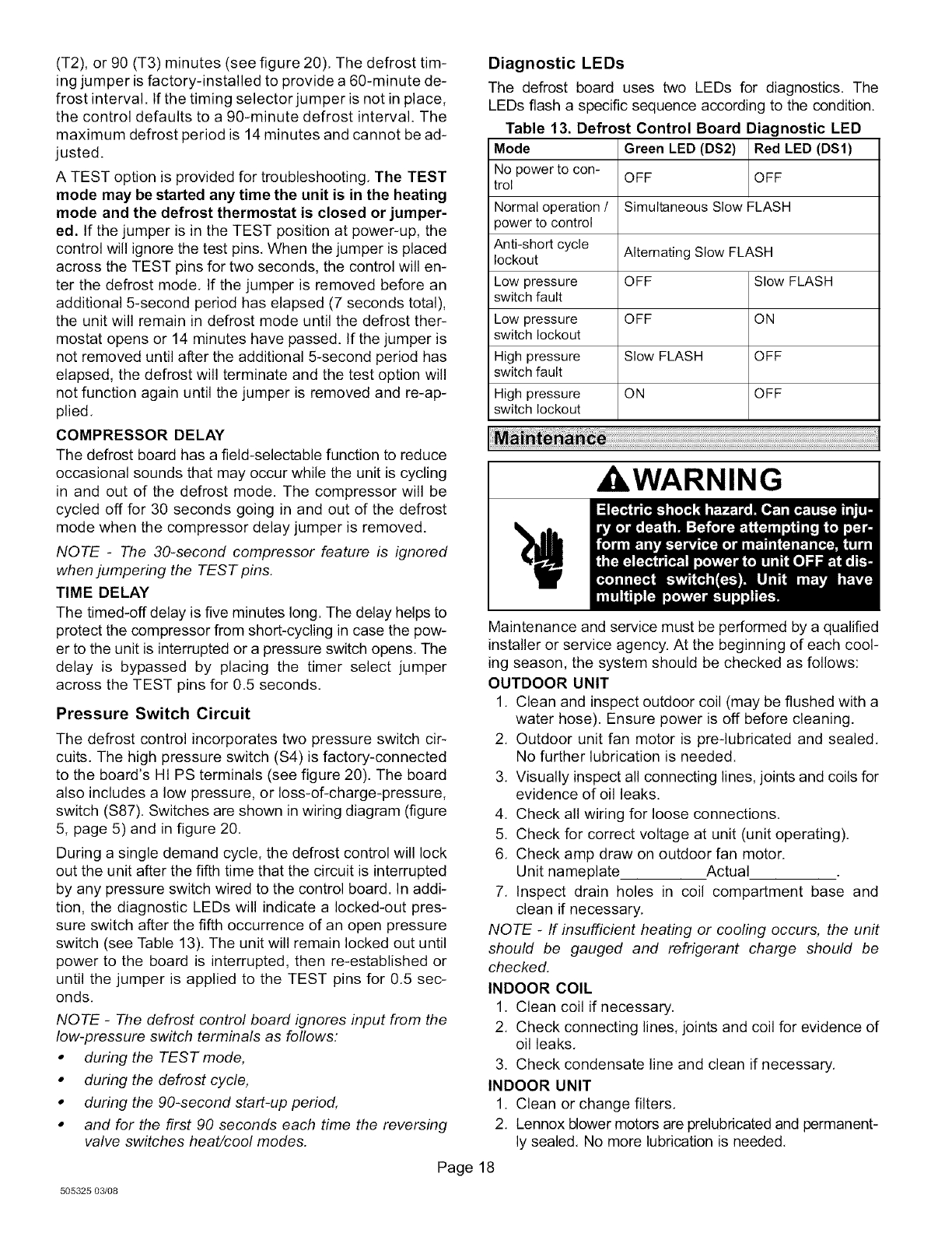
DEFROST CONTROL
The defrost control board includes the combined functions
of a time/temperature defrost control, defrost relay, diag-
nostic LEDs and terminal strip for field wiring connections.
See figure 20.
FIELD SELECT
TIMING PINS
TEST
PINS
COMPRESSOR
DELAY PINS
REVERSING
VALVE
LOW PRESSURE
SWITCH
DEFROST _"
THERMOSTAT
HIGH PRESSURE
SWITCH
ODSl
ODS2
0-0UT P2
Bt_€
YFOUT
o
DIAGNOSTIC
LEDS
24V TERMINAL
STRIP
CONNECTIONS
Figure 20.13HPX Outdoor Unit Defrost Control
Board
The control provides automatic switching from normal
heating operation to defrost mode and back. During com-
pressor cycle (call for defrost), the control accumulates
compressor run times at 30-, 60-, or 90-minute field-ad-
justable intervals. If the defrost thermostat is closed when
the selected compressor run time interval ends, the defrost
relay is energized and defrost begins.
DEFROST CONTROL TIMING PINS
Each timing pin selection provides a different accumu-
lated compressor run time period for one defrost cycle.
This time period must occur before a defrost cycle is initi-
ated, The defrost interval can be adjusted to 30 (T1), 60
Page 17
13HPX SERIES
(T2), or 90 (T3) minutes (see figure 20), The defrost tim-
ing jumper is factory-installed to provide a 60-minute de-
frost interval. If the timing selector jumper is not in place,
the control defaults to a 90-minute defrost interval. The
maximum defrost period is 14 minutes and cannot be ad-
justed.
A TEST option is provided for troubleshooting, The TEST
mode may be started any time the unit is in the heating
mode and the defrost thermostat is closed or jumper-
ed. If the jumper is in the TEST position at power-up, the
control will ignore the test pins, When the jumper is placed
across the TEST pins for two seconds, the control will en-
ter the defrost mode, If the jumper is removed before an
additional 5-second period has elapsed (7 seconds total),
the unit will remain in defrost mode until the defrost ther-
mostat opens or 14 minutes have passed. If the jumper is
not removed until after the additional 5-second period has
elapsed, the defrost will terminate and the test option will
not function again until the jumper is removed and re-ap-
plied,
COMPRESSOR DELAY
The defrost board has a field-selectable function to reduce
occasional sounds that may occur while the unit is cycling
in and out of the defrost mode. The compressor will be
cycled off for 30 seconds going in and out of the defrost
mode when the compressor delay jumper is removed.
NOTE -The 30-second compressor feature is ignored
when jumpering the TEST pins.
TIME DELAY
The timed-off delay is five minutes long. The delay helps to
protect the compressor from short-cycling in case the pow-
er to the unit is interrupted or a pressure switch opens, The
delay is bypassed by placing the timer select jumper
across the TEST pins for 0,5 seconds,
Pressure Switch Circuit
The defrost control incorporates two pressure switch cir-
cuits. The high pressure switch ($4) is factory-connected
to the board's Ht PS terminals (see figure 20). The board
also includes a low pressure, or loss-of-charge-pressure,
switch ($87). Switches are shown in wiring diagram (figure
5, page 5) and in figure 20.
During a single demand cycle, the defrost control will lock
out the unit after the fifth time that the circuit is interrupted
by any pressure switch wired to the control board. In addi-
tion, the diagnostic LEDs will indicate a locked-out pres-
sure switch after the fifth occurrence of an open pressure
switch (see Table 13). The unit will remain locked out until
power to the board is interrupted, then re-established or
until the jumper is applied to the TEST pins for 0.5 sec-
onds.
NOTE -The defrost control board ignores input from the
low-pressure switch terminals as follows:
•during the TESTmode,
•during the defrost cycle,
•during the 90-second start-up period,
• and for the first 90 seconds each time the reversing
valve switches heat/cool modes.
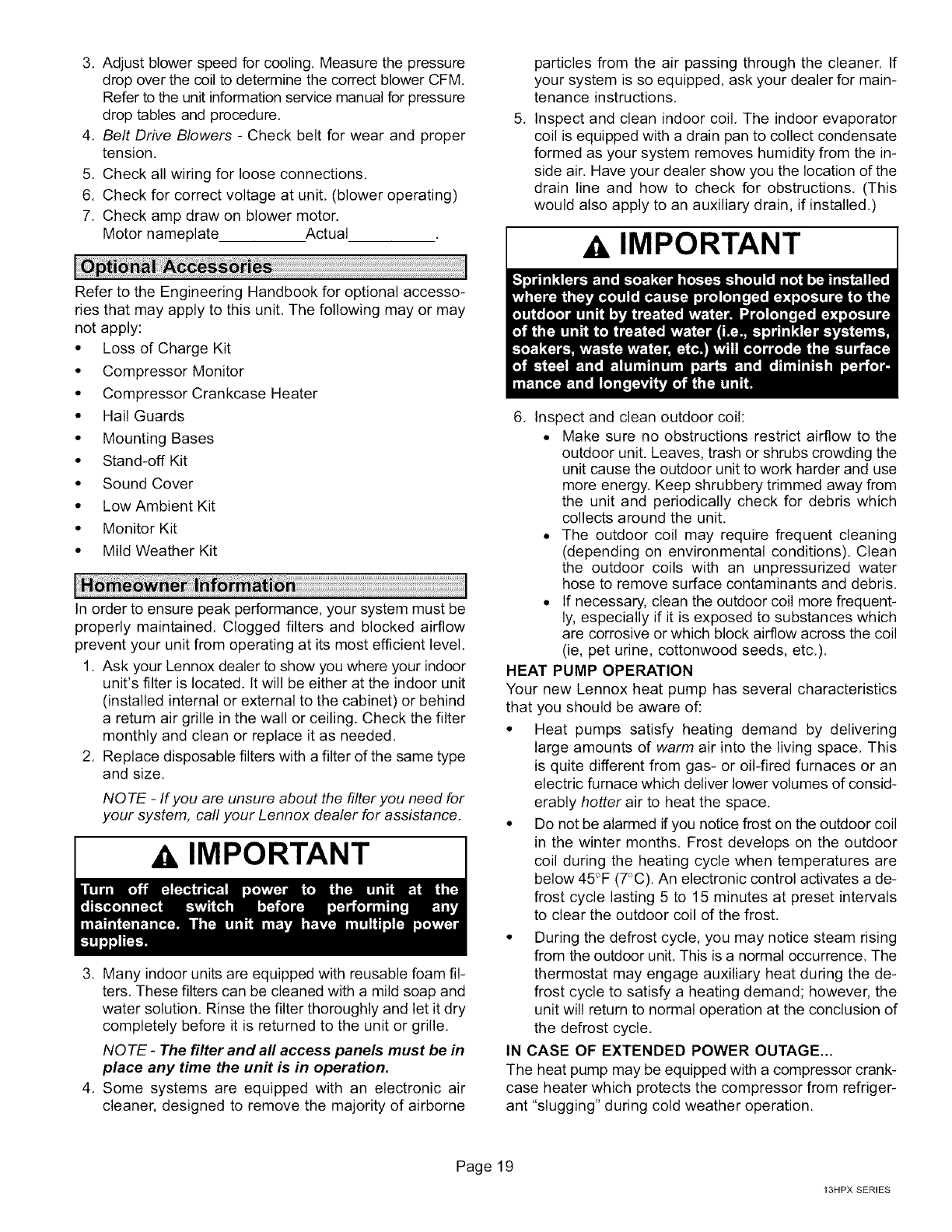
Diagnostic LEDs
The defrost board uses two LEDs for diagnostics. The
LEDs flash a specific sequence according to the condition.
Table 13. Defrost Control Board Diagnostic LED
Mode Green LED (DS2) Red LED (DS1)
No power to con- OFF OFF
trol
Normal operation /Simultaneous Slow FLASH
power to control
Anti-short cycle Alternating Slow FLASH
lockout
Low pressure OFF Slow FLASH
switch fault
Low pressure OFF ON
switch lockout
High pressure Slow FLASH OFF
switch fault
High pressure ON OFF
switch lockout
kWARNING
Maintenance and service must be performed by a qualified
installer or service agency. At the beginning of each cool-
ing season, the system should be checked as follows:
OUTDOOR UNIT
1, Clean and inspect outdoor coil (may be flushed with a
water hose). Ensure power is off before cleaning.
2, Outdoor unit fan motor is pre-lubricated and sealed,
No further lubrication is needed.
3, Visually inspect all connecting lines, joints and coils for
evidence of oil leaks.
4, Check all wiring for loose connections,
5. Check for correct voltage at unit (unit operating),
6, Check amp draw on outdoor fan motor.
Unit nameplate Actual
7, Inspect drain holes in coil compartment base and
clean if necessary,
NOTE -If insufficient heating or cooling occurs, the unit
should be gauged and refrigerant charge should be
checked.
INDOOR COIL
1. Clean coil if necessary.
2, Check connecting lines, joints and coil for evidence of
oil leaks,
3. Check condensate line and clean if necessary,
INDOOR UNIT
1. Clean or change filters,
2, Lennox blower motors are prelubricated and permanent-
ly sealed, No more lubrication is needed,
Page 18
505325 03/08
3. Adjust blower speed for cooling, Measure the pressure
drop over the coil to determine the correct blower CFM
Refer to the unit information service manual for pressure
drop tables and procedure.
4. Belt Drive Blowers - Check belt for wear and proper
tension,
5, Check all wiring for loose connections.
6. Check for correct voltage at unit, (blower operating)
7. Check amp draw on blower motor.
Motor nameplate Actual
Refer to the Engineering Handbook for optional accesso-
ries that may apply to this unit, The following may or may
not apply:
• Loss of Charge Kit
• Compressor Monitor
• Compressor Crankcase Heater
• Hail Guards
• Mounting Bases
• Stand-off Kit
• Sound Cover
• Low Ambient Kit
• Monitor Kit
• Mild Weather Kit
In order to ensure peak performance, your system must be
properly maintained. Clogged filters and blocked airflow
prevent your unit from operating at its most efficient level,
1. Ask your Lennox dealer to show you where your indoor
unit's filter is located. It will be either at the indoor unit
(installed internal or external to the cabinet) or behind
a return air grille in the wall or ceiling. Check the filter
monthly and clean or replace it as needed.
2. Replace disposable filters with a filter of the same type
and size,
NOTE -If you are unsure about the filter you need for
your system, carl your Lennox dealer for assistance,
AIMPORTANT
3. Many indoor units are equipped with reusable foam fil-
ters, These filters can be cleaned with a mild soap and
water solution. Rinse the filter thoroughly and let it dry
completely before it is returned to the unit or grille,
NOTE -The filter and all access panels must be in
place any time the unit is in operation.
4. Some systems are equipped with an electronic air
cleaner, designed to remove the majority of airborne
.
particles from the air passing through the cleaner. If
your system is so equipped, ask your dealer for main-
tenance instructions.
Inspect and clean indoor coil, The indoor evaporator
coil is equipped with a drain pan to collect condensate
formed as your system removes humidity from the in-
side air. Have your dealer show you the location of the
drain line and how to check for obstructions. (This
would also apply to an auxiliary drain, if installed.)
AIMPORTANT
6. Inspect and clean outdoor coil:
• Make sure no obstructions restrict airflow to the
outdoor unit. Leaves, trash or shrubs crowding the
unit cause the outdoor unit to work harder and use
more energy. Keep shrubbery trimmed away from
the unit and periodically check for debris which
collects around the unit.
• The outdoor coil may require frequent cleaning
(depending on environmental conditions). Clean
the outdoor coils with an unpressurized water
hose to remove surface contaminants and debris.
• If necessary, clean the outdoor coil more frequent-
ly, especially if it is exposed to substances which
are corrosive or which block airflow across the coil
(ie, pet urine, cottonwood seeds, etc.).
HEAT PUMP OPERATION
Your new Lennox heat pump has several characteristics
that you should be aware of:
• Heat pumps satisfy heating demand by delivering
large amounts of warm air into the living space, This
is quite different from gas- or oil-fired furnaces or an
electric furnace which deliver lower volumes of consid-
erably hotter air to heat the space,
• Do not be alarmed if you notice frost on the outdoor coil
in the winter months. Frost develops on the outdoor
coil during the heating cycle when temperatures are
below 45°F (7°C). An electronic control activates a de-
frost cycle lasting 5 to 15 minutes at preset intervals
to clear the outdoor coil of the frost,
• During the defrost cycle, you may notice steam rising
from the outdoor unit. This is a normal occurrence. The
thermostat may engage auxiliary heat during the de-
frost cycle to satisfy a heating demand; however, the
unit will return to normal operation at the conclusion of
the defrost cycle.
IN CASE OF EXTENDED POWER OUTAGE...
The heat pump may be equipped with a compressor crank-
case heater which protects the compressor from refriger-
ant "slugging" during cold weather operation.
Page19
13HPX SERIES
If power to your unit has been interrupted for several hours
or more, set the room thermostat selector to the "Emer-
gency Heat" setting to obtain temporary heat without the
risk of serious damage to the heat pump.
In Emergency Heat mode, all heating demand is satisfied
by auxiliary heat; heat pump operation is locked out. After a
six-hour compressor crankcase "warm-up" period, the
thermostat can be switched to the "Heat" setting and nor-
mal heat pump operation may resume.
Though your thermostat may vary somewhat from the de-
scription below, its operation will be similar.
TEMPERATURE SETTING LEVERS
Most heat pump thermostats have two temperature selec-
tor levers: one for heating and one for cooling. Set the lev-
ers or dials to the desired temperature setpoints for both
heating and cooling. Avoid frequent temperature adjust-
ment; turning the unit off and back on before pressures
equalize puts stress on the unit compressor.
FAN SWITCH
In AUTO or INT (intermittent) mode, the blower operates
only when the thermostat calls for heating or cooling. This
mode is generally preferred when humidity control is a
priority. The ON or CONT mode provides continuous in-
door blower operation, regardless of whether the com-
pressor or auxiliary heat are operating. This mode is re-
quired when constant air circulation or filtering is desired.
SYSTEM SWITCH
Set the system switch for heating, cooling or auto opera-
tion. The auto mode allows the heat pump to automatically
switch from heating mode to cooling mode to maintain pre-
determined comfort settings. Many heat pump thermo-
stats are also equipped with an emergency heat mode
which locks out heat pump operation and provides tempo-
rary heat supplied by the auxiliary heat.
INDICATING LIGHT
Most heat pump thermostats have an amber light which in-
dicates when the heat pump is operating in the emergency
heat mode.
TEMPERATURE INDICATOR
Temperature indicator displays actual room temperature.
PROGRAMMABLE THERMOSTATS
Your Lennox system may be controlled by a program-
mable thermostat. These thermostats provide the added
feature of programmable time-of-day setpoints for both
heating and cooling. Refer to the user's information manu-
al provided with your thermostat for operation details.
PRESERVlCE CHECK
If your system fails to operate, check the following before
calling for service:
• Make sure all electrical disconnect switches are ON.
• Make sure the room thermostat temperature selector
AND the system switch are properly set.
• Replace any blown fuses, or reset circuit breakers.
• Make sure unit access panels are in place.
• Make sure air filter is clean.
• Locate and record unit model number before calling.
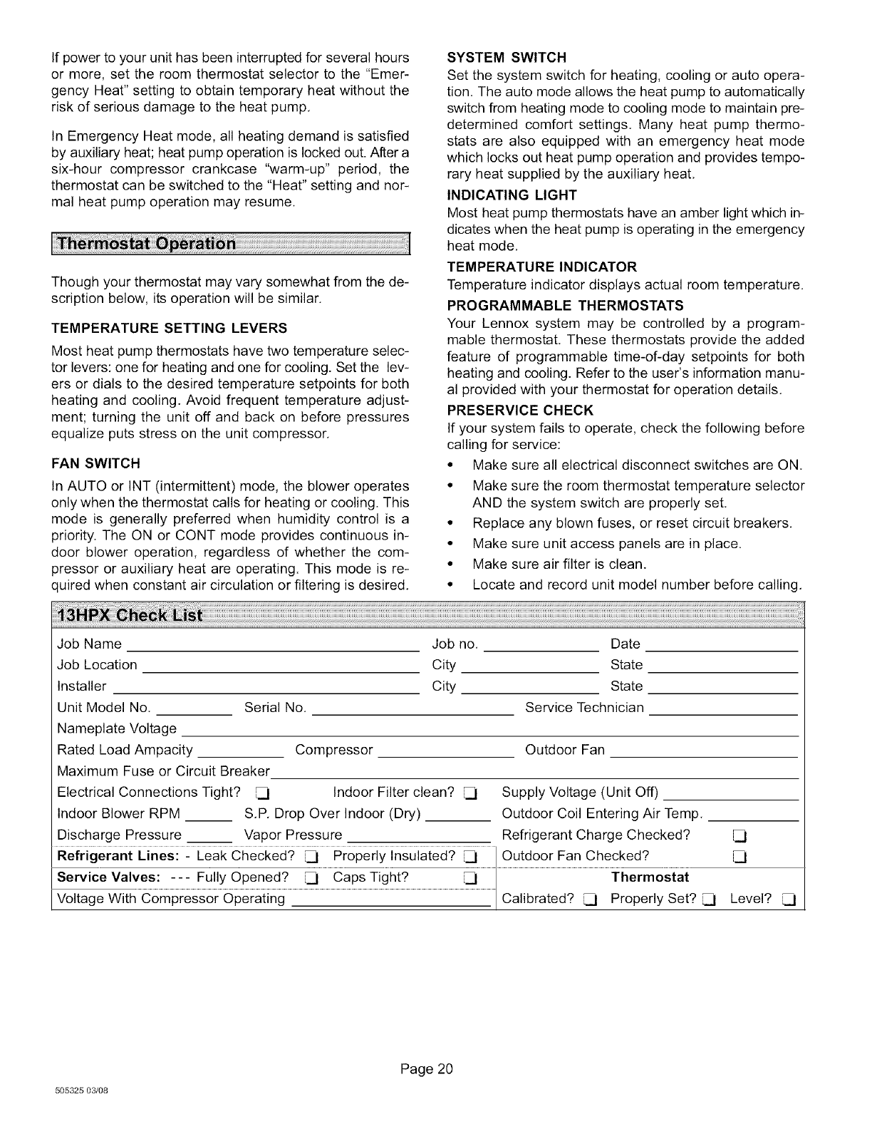
Job Name
Job Location
Installer
Unit Model No.
Nameplate Voltage
Rated Load Ampacity
Maximum Fuse or Circuit Breaker
Electrical Connections Tight? _]
Indoor Blower RPM
Discharge Pressure __
Serial No.
Job no. Date
City State
City State
Service Technician
Compressor
Indoor Filter clean?
S.P. Drop Over Indoor (Dry)
Vapor Pressure
Outdoor Fan
Supply Voltage (Unit Off)
Outdoor Coil Entering Air Temp.
Refrigerant Charge Checked?
es! _ Fu!!yOpened? _ CapsT!gh!? ...................................................................._ ...................... Thermostat
Votage Wth Compressor Operat ng Ca brated? _1 Properly Set? _1 Level? _1
505325 03/08
Page 20
